Valid for maintaining the following configurations:
Cargo Hold Robot
Tank Cleaning Robot
Magnetic Universal Crawler
Hull Cleaning Robot
Preparation
Operation
Maintenance & Repair
Symbol explanation
x x x
Read and understand the manual
Wear safety glasses
Wear safety gloves
Wear safety boots
Wear hardhat
Keep clear of pacemaker
Instruction steps
Warning - Risk of electrical shock
Warning - Risk of falling objects
Careful - strong magnets
Caution - Read the explanatory text
Careful - Risk of falling objects
Careful - Risk of pinching hand
Number of personnel required
Action can prevent damage
Introduction
This is the universal manual for all RAW0011 configurations. The manual contains instructions in safety, transportation, storage, preparation for use and maintenance. An overview of applicable RAW0011 models can be seen on next page.
Read the safety instructions in this document carefully before first use.
Read all documentation before first use.
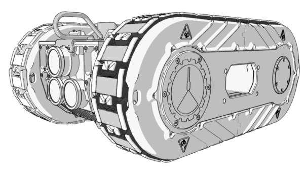
Hold Robot [CHR] RAW0011 Robot models - Manual is valid for all RAW0011 products, examples shown below
Tank Cleaning Robot [TCR]
General robot information - Safety
CLIIN shall not be liable for any injury or damage to people or property caused by non-compliance with instructions and the contents of this manual.
Warning!
magnetic fields
Keep away from pacemakers
(0.60 m or 2 ft)
Danger of pinching in magnetic belts. Keep hands and feet away when belts are moving.
General robot information - Safety
Always keep clear of high pressure spray. Do not touch high pressure water or point high pressure tool towards anyone.
• Only use approved equipment for lifting.
Danger of pinching/severe damage to fingers when wheels are moving. Never touch marked areas or belt when power is on.
• Only trained and qualified personnel must perform lifts.
• Plan the lift and lifting route before execution, to minimise the risk of accidents.
• Never stand underneath objects being lifted.
• Always read safety instructions for load arrestors before using the robot.
• Never stand underneath the robot when being operated
General robot information - Safety - Magnets
MIN 60 cm from magnets
Magnets from robot can influence the steering mechanism on the Control Box.
If the Control Box is close to the magnets, start will be prevented.
Keep credit cards, watches and phones away from magnets.
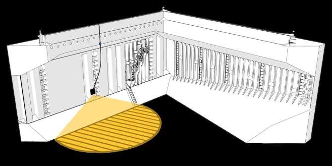
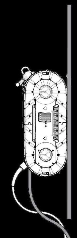
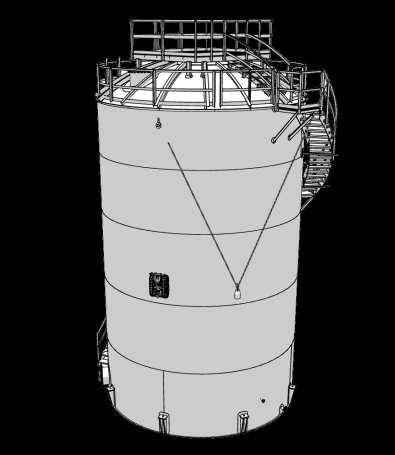
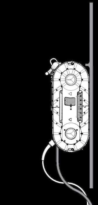
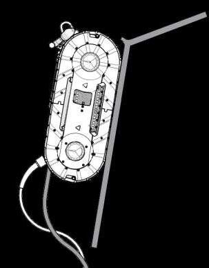
General robot information - Safety - Safe Distance
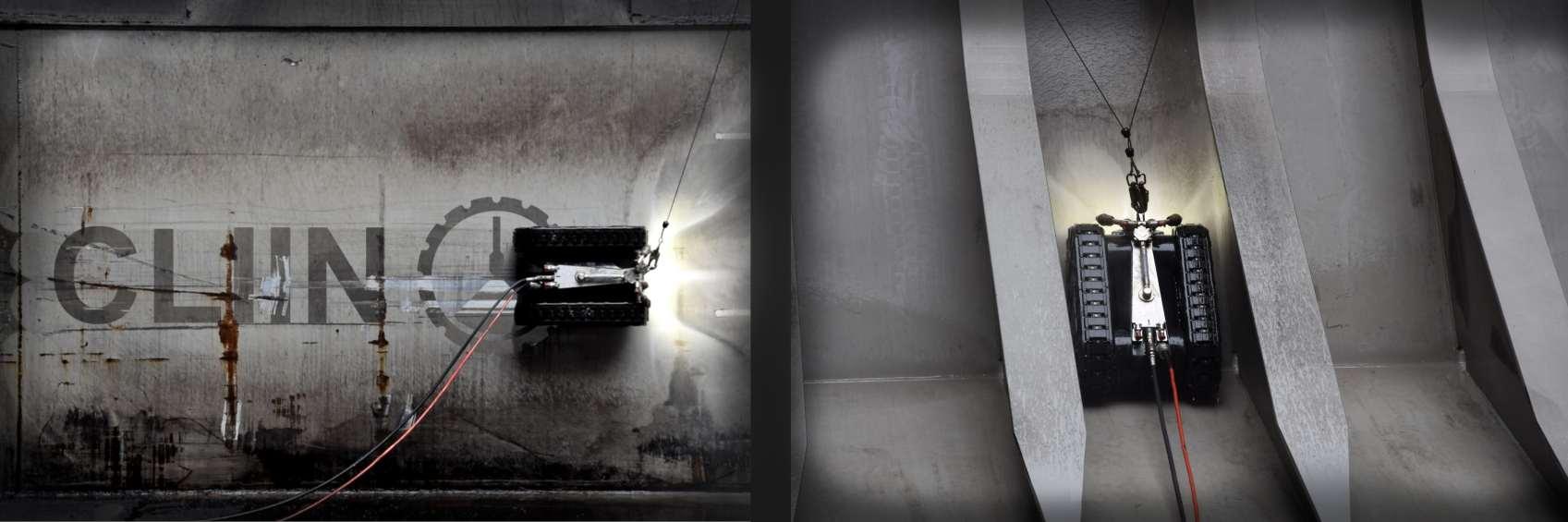
Cargo hold environment for illustration purposes. Safety instructions are universal and applies for all use cases.
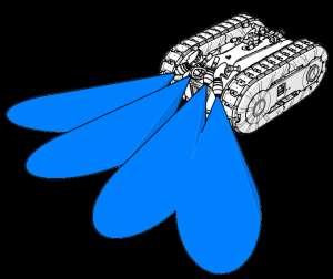
Never stay under the robot when operated. Robot can swing if detached from the wall and caught by load arrestors - stay in safe distance.
Always use hard hat, safety boots and other appropriate PPE when operating the robot.
Always use two load arrestors when operating the robot in a cargo hold and on storage tanks.
Lock the carabiner before driving.
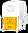
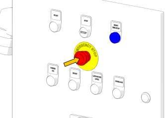
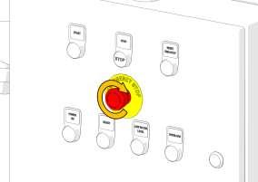
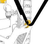
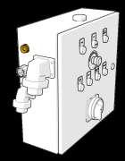
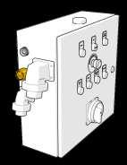
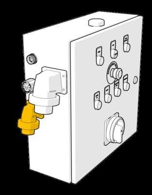
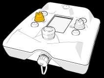
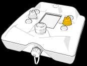
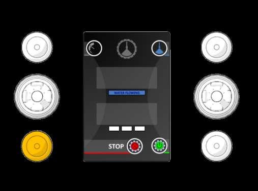
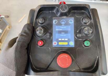
General robot information - Safety - Emergency Button
Control cabinet on high
Emergency buttons
Press the emergency button in the case of an emergency or if an unexpected situation occurs. The Robot will enter “stop mode” and can be restarted from the Control Box.
The emergency button does not shut down the In-line heater or other auxiliary equipment if such is used. Use the switches on the In-line Heater. The In-line Heater burner will, however, pause when the water supply is stopped.
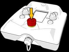
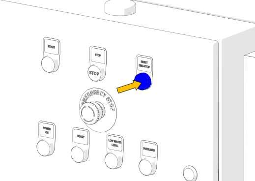
Control box emergency button
The control box emergency button is ONLY functional when all the following criteria are met:
• Control box connected to the High-pressure System or Electrical cabinet.
• Robot connected to the High-pressure System or Electrical cabinet.
• 230/110 V power connected to the High-pressure System or Electrical cabinet.
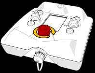
General robot information - Safety - Emergency Button
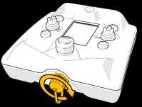
Before releasing the emergency button, investigate why the button was pressed and assess the situation. When the situation is safe the emergency button can be released.
1. Release the emergency button by twisting it clockwise.
stop button on the control box (5 seconds) to reset the emergency mode.
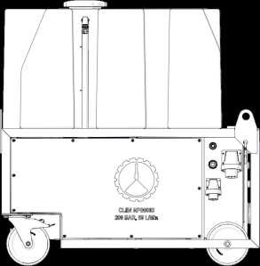
General robot information - Standard Delivery Overview &
Specifications
Voltage robot
Frequency
-230 V
Current robot [32 A / 110 V] or [16 A / 230 V]
110/230 V connection
2 poles + earth, 6H - Connected to electrical cabinet (High-pressure pump or stand-alone)
Light power 5000 lumens
Ambient
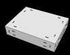
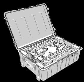
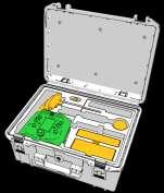
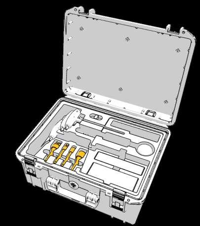
BOX0010
Tool box with tools for maintenance.
Box dimensions (L x W x H)
CAGE dimensions (L x W x H)
x 694 x 381 mm (47.0 x 31.3 x 49.2 in)
x 677 x 1485 mm (33.4 x 26.6 x 58.5 in)
Control cabinet for robot always included
Part of HPS000X (High-Pressure System)
or as stand alone cabinet.
230 V electrical cable included in chosen solution.
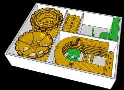
BOX0005
Spare parts - Recommended essential spares.
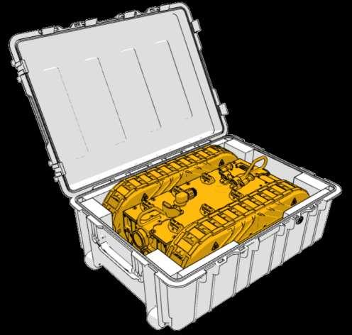
General robot information - Equipment handling methods
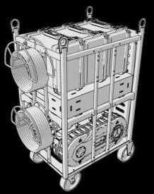
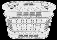
RAW0011 Cage option [CAGE001]
Robot stored on a welded stainless cage, where misc. equipment can be stored as well.
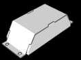
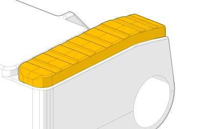
ORRAW0011 Casing option [M000187]
Robot including protective casing
Never store equipment in splash zones on vessels - e.g forecastle area.
- Avoid splash from waves and heavy weather.
x
Included depending on purchase
1-5 x
KIT0019 - Screw kit
MHH0002 (60 Hz) (40° nozzle 12.4 lpm)
MHH0136 (50 Hz) (40° nozzle 10.4 lpm)
MHH0013 (50 Hz) (20° nozzle 16.4 lpm)
62 x
Always included in spare part box
1 x
Misc. for machines and tools
KIT0001 50/500 hour redress kit for HPS0004/5
MIS0080
Diesel Filter Cartridge for In-line Heater
KIT0020 Oil for air lubrication
Center Rubber Clear:
6 x
Included depending on purchase
2 x
1 x
MA00086
Polymer mounting bracket.
Always included in spare part box
1 x
6 x M000831 Tool bracket. Locking pin: MIS0001
MA00103 Free wheel. Impact part / Consumable.
M000675 Drive Wheel. Impact part / Consumable.
6 x M000943 Track Screens Consumables.
M000524 Track steers Consumables.
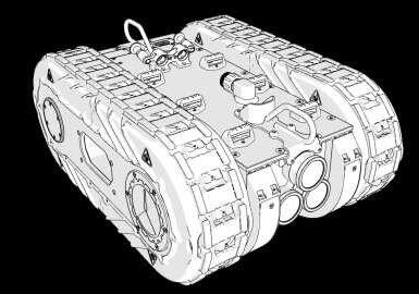
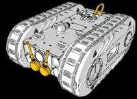
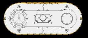
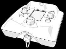
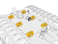
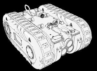
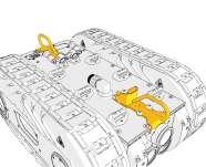
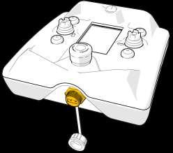
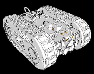
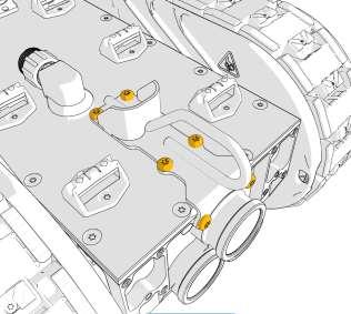
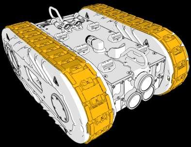
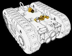
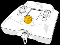
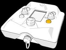
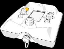
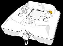
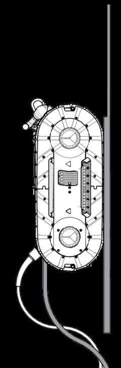
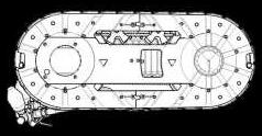
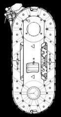
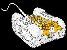
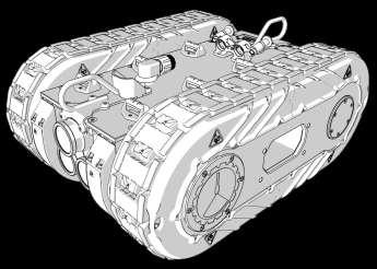
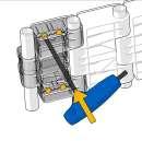
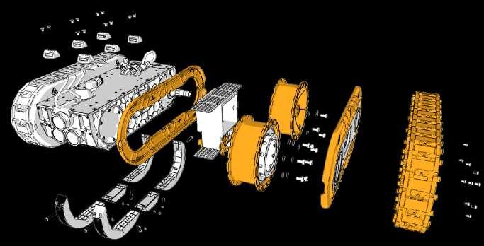
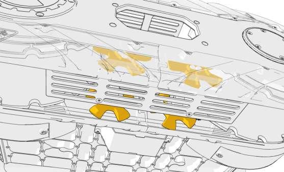
General robot information - Overview
Mounting brackets for mounting equipment on top of the robot. x2 x6
Locking pin for fastening high pressure hose or other tool hoses or cables.
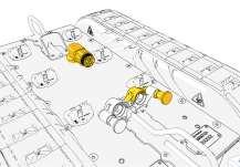
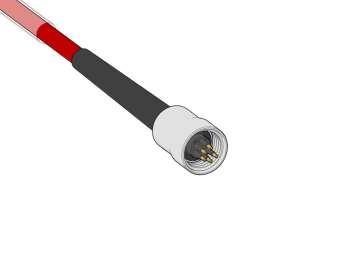
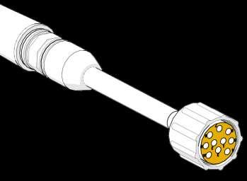
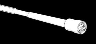
Hybrid connector. Used to get signal and power from control cabinet to robot.
Area for mounting camera or other auxillery outlets.
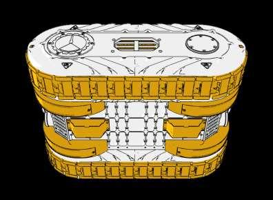
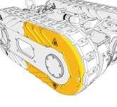
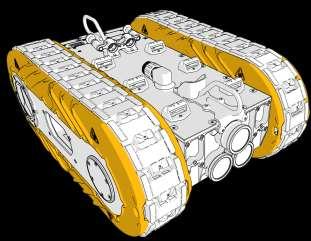
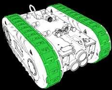
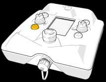
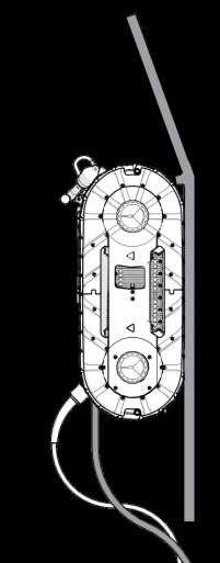
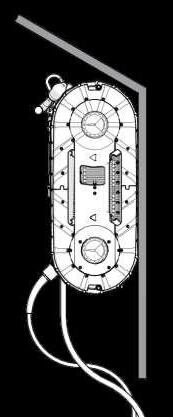
General robot information - Overview
tracks to support magnetic belts. Can be replaced when worn or damaged.
Anchors for securing robot to Load arrestors. Can be placed in both ends.
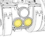
Front light to enable cleaning in dark conditions. Do not look directly into light.
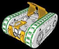
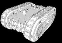
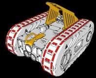
General robot information - Lack of friction - configuration optimiziation
In special cases, the robot may lack friction to climb to the wanted areas. This can happen in the following scenarious:
• Sub zero temperatures
• Driving on ferrousious surfaces with a steel thickness below 10 mm
• Driving on unwashed or very slippery cargo
• Special coating system with very low friction
Solutions:
Change rubber type
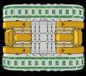
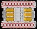
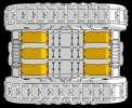
Add block magnets
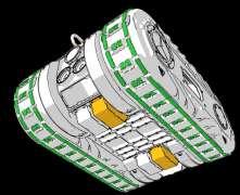
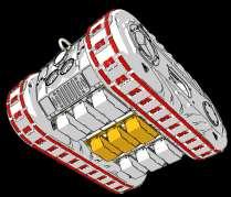
General
Cargo Hold Robot [CHR] Tank / Hull Cleaning Robot [TCR / HCR]
Two added magnets on a cargo hold robot will significantly increase the friction. Adding magnets might limit the possibility of 0-90° transitions due to excesive power drag.
Adding three additional center magnets will increase adhesion, but risk chipping paint on welding seems.
Changing rubber from green (low friction high durability) to clear type, will increase friction significantly, but lower the durability.
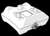
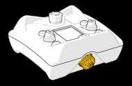
Control box - Manual System Updates Through USB
All system updates from CLIIN are done via USB connection.
When updating the firmware through the control box, the entire system will be updated.
When the system is not being updated, the USB connector must be protected with the protection cap.
Before first use - Electrical installation
installation must be performed by an authorised electrician.
MA00055 - 230 V electric cable - 3 cores @ 1.5 mm2
Voltage rating: 110-230 V
Current rating: 16-32 A
Fit a local standard plug at 110-230 V cable before the cable can be used. The plug must comply with applicable legislation and the specifications above.
Cable to be connected to electrical cabinet placed on High-Pressure system - or as stand-alone cabinet.
Before first use - Mounting Magnets after Air Freight
All magnets for the robot will be transported in a shielded box if transported by air freight.
All magnets must be mounted before first operation. Please follow mounting instructions carefully.
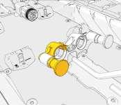
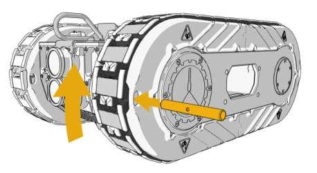
Before first use - Mounting Magnets depending on configuration
Mount the magnetic belts by following the guide in the back of this manual.
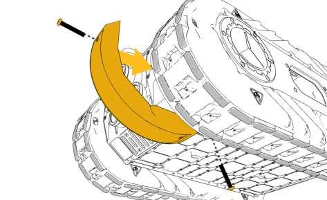
Mount bottom curved magnets if needed for the magnet configuration.
Before first use - Mounting Magnets depending on configuration
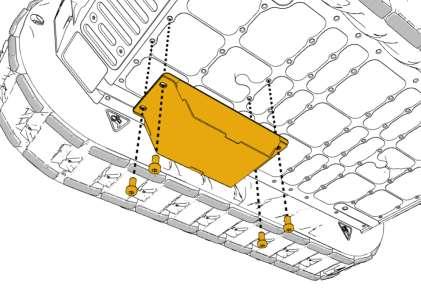
Mount bottom block magnets. The placement and amount of block magnets can be adjusted depending on the purpose.
xA
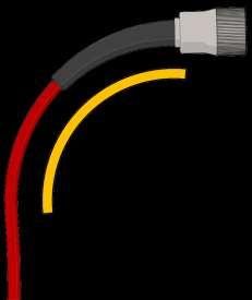
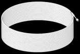
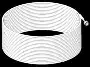
Storage & Handling - Cable Handling
Do not plug in cable when twisted. Always untwist cables before use.
Applies for all cables.
Do not bend cable more than R200 mm. Bending cable more may result in system failure due to loss of power or signal.
Applies to all cables.
Min R200 mm
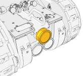
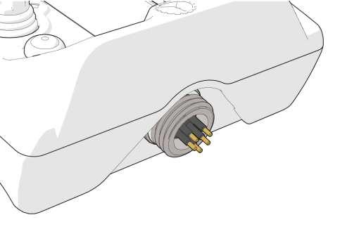
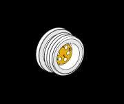
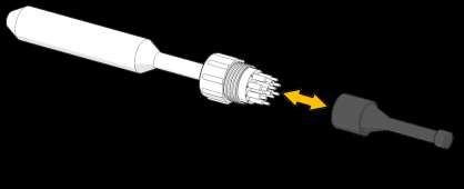
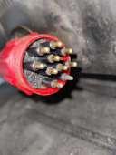
Storage & Handling - Cleaning Robot connector
If dirty: clean robot hybrid connector with fresh water only.
Do not use high pressure water.
Unplug cable before cleaning.
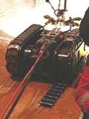
Storage & Handling - Remove Remnants From Magnets
x6
Failing to remove remnants or debris from magnets can result in the robot falling.
Remove remnants from magnets on the bottom magnet system before, during and after operation. The bottom system enables transition between surfaces and enables driving on uneven vertical surfaces without Detaching.
x2
Failing to remove remnants from magnetics belts can result in excesive wear or belts breaking.
Remove remnants from magnets on the magnetic belts before, during and after operation.
Storage & Handling - Cleaning Robot Before Storage
Clean robot with fresh water before storage.
Store robot in box to prevent damage.
Allow to dry before storage to avoid corrosion.
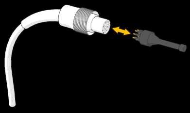
If dirty: clean control box connector with fresh water only. Do not use high pressure water.
Unplug cable before cleaning.
Ensure USB protection cap is mounted before cleaning.
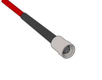
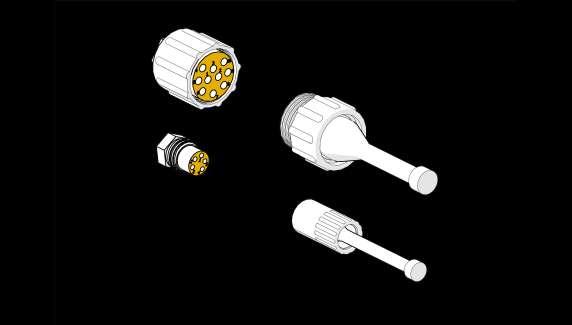
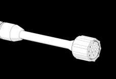
Storage & Handling Cleaning Cable and Cabinet Connectors
Signal Cable
M000136 & Cabinet
Hybrid Cable
M000159 & Cabinet
Turn off power on electrical cabinet before cleaning connectors. Disconnect cable before cleaning.
If dirty: clean connectors with fresh water only. Do not use high pressure water.
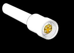
Grease female protection plugs if as-
use 1 small fingertip of grease (MTO0003) for easy assembly.
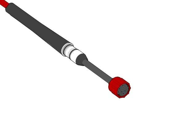
Storage & Handling - Greasing Female Connectors
M000159 / M000668
Hybrid Cable
M000136
Grease female connectors if assembly is not easy. use 1 small fingertip of grease (MTO0003) for easy assembly. x4
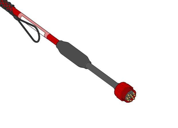
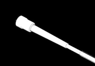
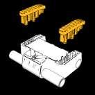
Storage & Handling - Mount Protection Plugs On Cables and Cabinets
Store protection plugs in the spare part box when the cables are in use. To prevent loss and damage.
Storage & Handling - Storing Plugs During Operation
Mount protection plugs, when signal cable is not in use.
This is important to prevent connection failure.
Mount protection plugs, when hybrid cable is not in use.
This is important to prevent connection failure.
PN: MEA0028
PN: MEA0029 PN: MEA0022 PN: MEA0023
1 - 2 1 2
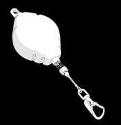
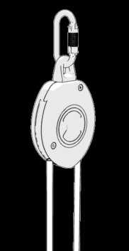
Before each installation and after each activation, the arrest function must be verified by pulling the wire/rope.
Before each installation and after each activation, the wire/rope must be inspected for mechanical damage. The entire wire/rope must be rolled out for inspection.
Before each installation and after each activation, the housing must be inspected for mechanical damage.
If any mechanical damage is observed, the load arrestor cannot be used.
Always follow the guidelines and maintenance requirements from the load arrestor manufacturer.
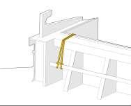
• Properly secure load arrestor with slings or similar approved method on a stable structural part, depending on the use case.
• Inspect equipment for attachment before mounting and after each activation during use.
Rope based system
Wire based system
Prepare System For Use -
system Placement
MAX 15 meter between load arrestors
Always use two load arrestors
3
3 -
4
4
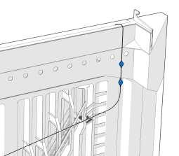
Load arrestor must be placed in a way to secure free roll out of wire, to prevent damages to the wire/rope.
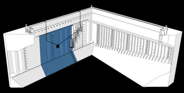
When load arrestors are placed correctly, the blue area inbetween can be cleaned.
When cleaning is completed, one load arrestor can be moved to the next suitable place-
Cargo hold environment for illustration purposes. Safety instructions are universal and applies for all use cases.
OR OR
Secure in front or rear anchor depending on the job.
Mount a cable tie specified for 80 kg (176 lbs) in the slot in the turtle shield and secure the load arrestor rope. This will keep the rope away from the front tool if needed.
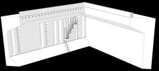
Prepare System For Use - Safety - Load Arrestor system Placement
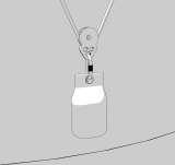
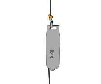
Recommended setup for load arrestors on tank cleaning
Hang sandbag in pulley. Sandbag will move freely up and down.
110-230 V electric cable 5 - 7 x3 5 6 7
MA00055
M000136
Signal cable
M000159 /
Hybrid cable
• Go through the entire length of all the electric cables for damage before use. If the insulation is breached the cables must be changed.
• Visually check the plugs in both ends for damage.
• Check and clean the plugs of dirt. See preparation page 26 for cleaning instructions.
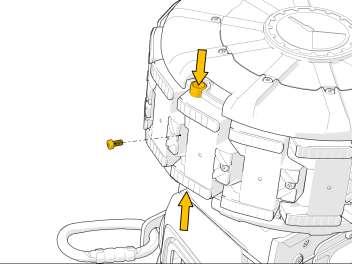
Control that all 6 screws are tight.
Control condition around top plate mechanics around the load arrest anchor. Do not use robot if damage is observed.
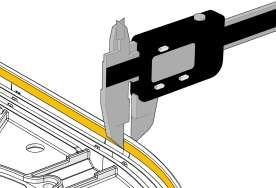
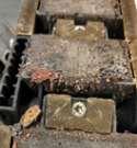
Prepare System For Use - Inspect Screens
Inspect track support screens and surrounding mechanics for visible damages.
Replace parts if belts are prevented from moving correctly. Read the maintenance and repair section in this manual for instructions for replacements.
Remove and Inspect screens [M000943]
thickness. Lower part of front screens will be worn by magnetic belts over time.
If thickness is less than 2 mm, screens must be replaced. Screens may be rotated if thickness on other screens are ok. Measurement applies to entire rim. 9 - 10 9 x2
x8
It is an advantage to do this inspection after each operation and plan maintenance to prevent downtime.
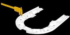
Prepare System For Use
11
11 - 12
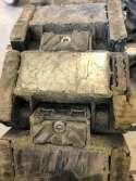
Inspect magnetic belt for large debris that can prevent belt from moving correctly. Remove these if found.
Failing to remove remnants can result in damage to magnetic tracks.
12
Inspect wear on rubber pads - if no track pattern is visible, rubber pads must be replaced. See manual maintenance for instructions.
Inspect magnet joints - if heavily worn or risk of magnet detaching from housing - the magnetic joint must be replaced.
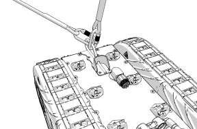
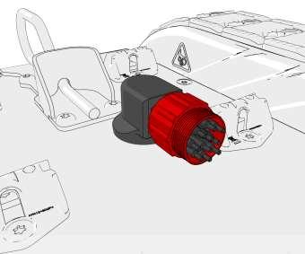
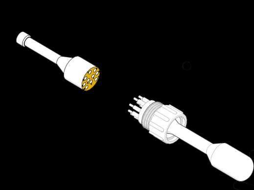
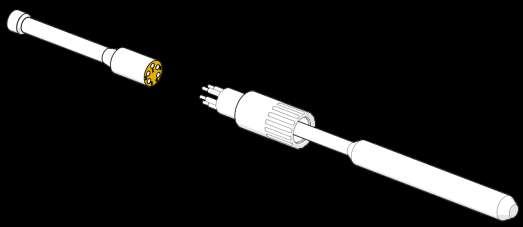
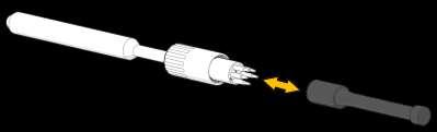
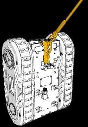
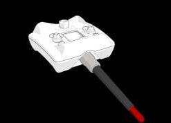
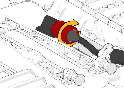
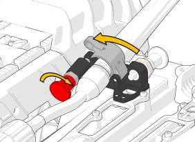
Prepare System For Use - Connect Signal Cable
Do not connect when power is on - Will cause electrical arcing and will damage the connector.
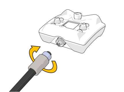
Make sure to push the connectors thoroughly together. No air gap in connector nuts must be present.
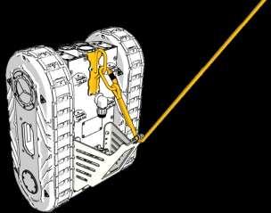
Lock the bracket by turning the red knob. 16
Close the connector bracket to secure cable relief.
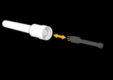
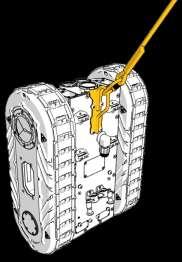
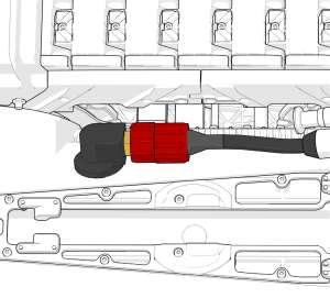
Prepare System For Use - Secure connection
Make sure to connect hybrid and signal cable prior to connecting the 110/230 V supply.
Do not connect 110/230 V when power is on - Will cause electrical arcing and will damage the connector.
Turn off or unplug the cable at the panel breaker before mounting.
110-230 V power inlet from external supply
MA00055
110-230 V electric cable
• Go through the preparation steps before continuing with operation.
• Make sure all cables are connected correctly before starting the operation.
• Do not spray water on electrical wiring or installations.
• Do not leave the robot unattended with power on.
Turn off the panel breaker before leaving.
• Always be at least 2 people participating in the operation for safety reasons.
• Remove obstacles under the robot operating area.
• Never stand under the operating area.
Cargo hold environment for illustration purposes. Safety instructions are universal and applies for all use cases.
Never stay under the robot when operated. Robot can swing if detached from the wall and caught by load arrestors - stay in safe distance.
Always use hard hat, safety boots and other appropriate PPE when operating the robot.
Always use two load arrestors when operating the robot regardless of the job.
Lock the carabiner before driving.
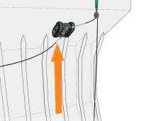
Always make sure that the rope/wire is tight from the load arrestor to the robot
If the wire is hanging loose from the load arrestor to the robot, it may be fixed by pulling the wire all the way out and in again. If the problem is not solved, it is not allowed to use the load arrestor during the operation.
If the rope is not tightened, add more weight to the free end of the rope. See the online manual for correct setup.
Rope based system
based system
Wire
OR
MAX 15 meter between load arrestors
Always use two load arrestors
Load arrestor must be placed in a way to secure free roll out of wire, to prevent damages to the steel wire.
When load arrestors are placed correctly, the blue area inbetween can be cleaned. When cleaning is completed, one load arrestor can be moved to the next suitable place-
Cargo hold environment for illustration purposes. Safety instructions are universal and applies for all use cases.
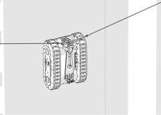
Magnets from robot can influence the steering mechanism on the Control Box.
MIN 60 cm from magnets
If magnets are close to the Control Box, start will be prevented. Warning! magnetic fields
Keep away from pacemakers (0.60 m or 2 ft)
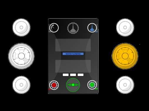
Press the emergency button to instantly hold the robot in place and prevent any movement. If auxilliary equipment is connected, this will stop running. Follow the instructions on the screen to reactivate the system.
Press the emergency button if an unexpected situation occurs.
Twist the emergency button clockwise to release the button.
Verify the max allowable current at the panel breaker. The breaker must comply with:
32 A / 110 V
16 A / 230 V
110-230 V power inlet from external supply
2
3
4
• Go through the entire length of all the electric cables for damage before use. If the insulation is breached the cables must be changed.
• Visually check the plugs in both ends for damage.
• Electrical shock or system failure can occur if operation is performed with damaged cables.
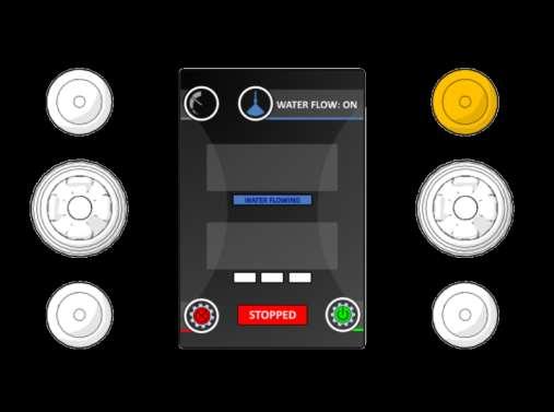
Ready to drive
Start robot by pressing the green button. The robot is now activated for driving by using the joysticks. After 15 seconds with joystick inactivity, the robot is put in STOP mode.
Press the green button to reactivate the drive mode.
Speed limit adjustment. Short press to change speed limit between; slow, medium & fast. Clean with slow speed when cargo is dirty. Clean with fast speed when the cargo is easy to remove. Speed mode is indicated by white rectangles.
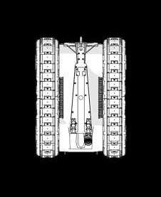
Control forwards and backwards movement with the left joystick.
Both robot tracks will move at the same speed.
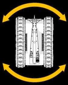
Turn robot left/right by using the right joystick. The robot tracks will move opposite of each other if the robot is not driving forwards or backwards.
Use both joysticks at the same time to steer more gently
Turn on water by long-pressing for 2 s.
Turn off water or auxilliary equipment by short press to minimize usage when cleaning.
Stop robot when motion is not required.
Robot is automatically stopped when no joysticks are touched for 15 seconds.
Stopped
The robot is able to pass larger welding seams up to 10 mm in
The robot is able to pass larger differences in plate thickness. Either to thicker or thinner.
The robot can pass a penetration, if it is not on a vertical surface, e.g. from a stool to the front of a corrugated bulkhead.
Turn off water or other auxiliary equipment and drive with slow speed.
Approach the weld perpendicularly
Overhang / Topside
The robot can make a transition to overhang / topside tank.
Angles up to 90° relative to vertical can be passed.
Approach the transition perpendicularly (approximately 90° to the transition).
The robot cannot pass large penetrations on a vertical bulkhead / surface.
Use Ladder [MA00051/52/53] to pass this obstacle if available.
The robot cannot fall into the lower space of a corrugated bulkhead, or similar inside geometries, where passing angles are above 180°.
Note that some tools cannot make a 90° transition without damaging the tool. Check the separate use manual for tool capabilities.
90° angle
? How to clean with which tool?
Follow the specific cleaning guide delivered to your application. There are various manuals for cleaning different applications. The correct sequence and tool selection can be found in each cleaning manual.
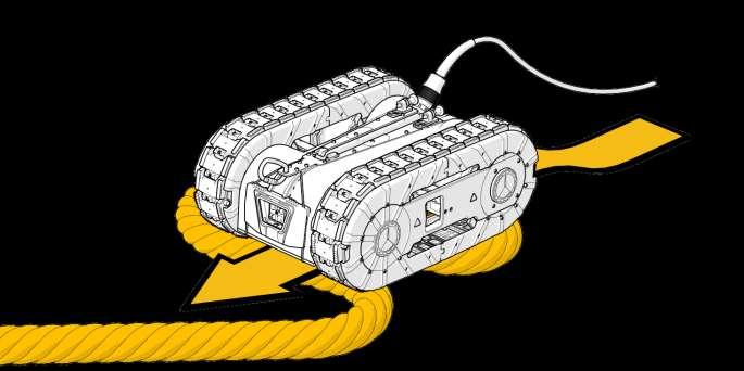
Drive on a thick robe, a wodden plank or another non-ferrous material to detach the robot from the tank top or another steel surface. When the robot is detached from the steel surface, it is ready to be switched off.
2
Cut the power at the panel breaker before disconnecting the AC 110-230 V
Supply to prevent arcing/damage to connectors in the system.
2 - 8
3 4 5
Unplug the hybrid cable
Clean and grease connectors
Mount protection plugs
Unplug the signal cable
Clean and grease connectors
Mount protection plugs 6 7 8
Operation - Shutdown
Clean robot with fresh water and remove remnants from magnets to prevent corrosion during storage.
Lift the robot into the box for storage. Use at least two trained personnel or approved lifting equipment. the box. Allow to dry before closing for storage.
Operation - Shutdown
This concludes the operation and shutdown instructions.
• Plan ahead - and follow the preparation steps to avoid downtime during next operation.
• If problems occur during operations - see maintenance chapter for troubleshooting.
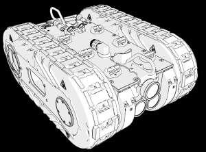
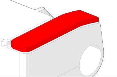
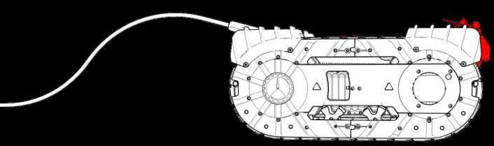
Troubleshooting - Safety & warranty
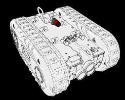
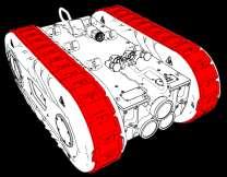
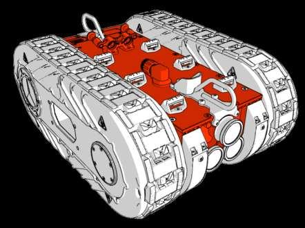
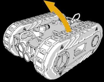
• No modification must be made to the Robot without written consent from CLIIN.
• Do not open the watertight housing of the Robot. Risk of electrical shock.
• Do only replace external parts described (white on below image) in this manual or instructed by CLIIN.
• Any warranty of the system will be void if the mentioned restrictions are not met.
If rope is not tight during operations, the load arrestor wheel can be sprayed with:
Würth Multi 2000 Oil
OBS! - Do NOT dissasemble load arrestor!
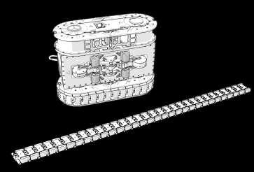
Troubleshooting
Magnetic belts are broken
Problem:
Possible cause: Solution:
Dirt, scales or other remnants are stuck between the links in the magnetic belt.
1. Retrieve the robot and the magnetic belt.
2. Remove the magnetic belt.
3. Remove remnants from the belt and replace broken magnetic track links.
4. Note: If the belts break, the track support screens are likely to be broken as well.
Replace screens if damaged according to the maintenance guide.
Troubleshooting
Magnetic belts are broken
Problem:
Possible cause: Solution:
Failing to replace track supports when worn.
1. Retrieve the robot and the magnetic belt.
2. Remove the magnetic belt.
3. Remove remnants from the belt and replace broken magnetic track links.
4. Replace cracked track supports
5. Note: If used track supports are mounted - the thickness of the rim on these must be verified according to the preparation steps.
Troubleshooting
Lack of Friction - Ability to pass obstacles
Possible cause: Solution: Problem:
Failing to replace rubber pads when worn.
1. Retrieve the robot and the magnetic belt.
2. Remove the magnetic belt.
3. Remove remnants from the belt and replace broken magnetic track links.
4. Replace cracked track supports
5. Note: If used track supports are mounted - the thickness of the rim on these must be verified according to the preparation steps.
is shown on control box
Solution:
Hybrid or signal cable has 1. Inspect if cables are cut or kinked
2. Try to replace cables and check connection
3. Replace cables if problem is solved.
is shown on control box
Connector is not fully
Solution:
1. Cut power at the panel breaker.
2. Check if connector nut is fully closed.
3. Disconnect connectors.
4. Clean, grease and reassemble connectors.
is shown on control box
Solution:
Hybrid or signal cable has 1. Cut power at the panel breaker.
2. Inspect if connectors are severely damaged due to arcing.
3. Always follow manual instructions to prevent arcing.
4. Clean and grease and retry connection.
5. If connectors are too damaged, contact CLIIN for a solution for a replacement or spare part.
Consumables - Common spare part overview
The most common consumables on the robot is shown below including estimated lifetime with normal use.
* The operational cost examples are calculated with 2024 prices
* Tank cleaning wears approximately 25% less than cargo hold cleaning
Operational costs
Use case examples
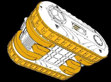
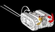
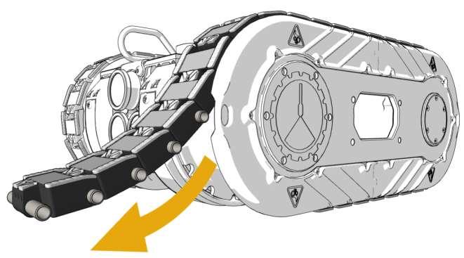
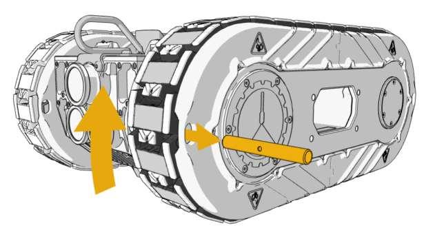
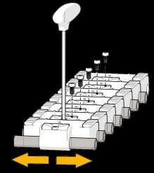
Remove Belt
Drive robot onto a thick rope, wodden pallet or similar nonferrous material to detach it from the steel surface. Flipping the robot is a two-man job.
Flip the robot to stand on the side, when it is free from steel surface. Grab the holes at the sides.
Careful! danger of pinching hand and fingers.
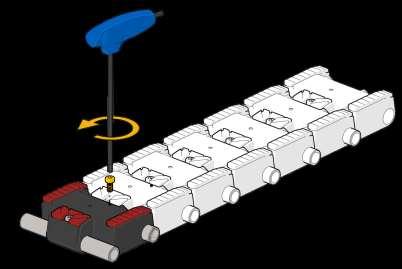
Drive forward on control box to remove belt.
Set speed limit to slow.
press stop on the control box for safety when magnetic belt is removed.
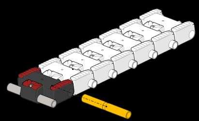
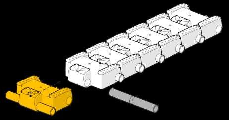
Cut power after removing the magnetic belts. And unplug connector.
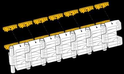
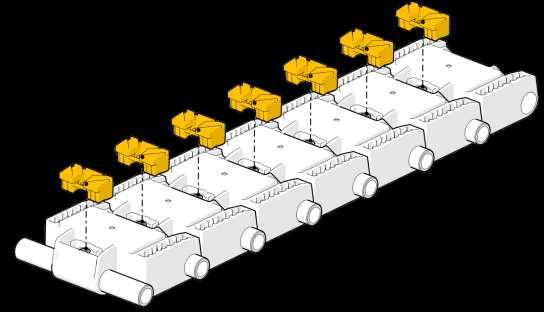
Maintenance - Replace Rubber Pads or Magnetic Tracks
Maintenance - Replace Rubber Pads or Magnetic Tracks
Push out side rubber pads from behind.
Pay attention to cracks in polymer housing.
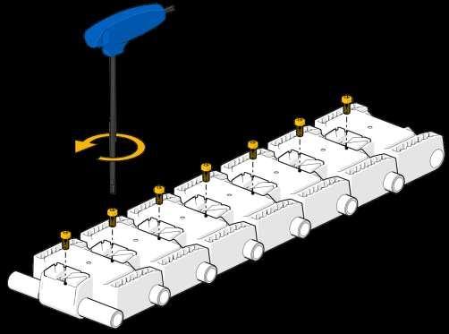
- Replace Rubber Pads or Magnetic Tracks
Gently remove all screws between the tracks.
Maintenance - Replace Rubber Pads or Magnetic Tracks
by hand.
Maintenance - Replace Rubber Pads or Magnetic Tracks
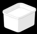
Soapy water
Center pads
Side pads
Use cold soapy water to ease assembly of new rubber pads. Press the rubber into the magnetic tracks while they are still wet.
Gently hit the rubber while they are still wet with the rubber hammer.
MTO0004
- Replace Rubber Pads or Magnetic Tracks
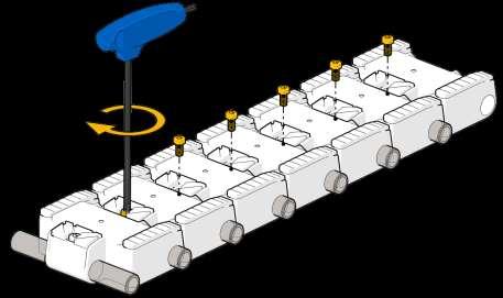
MTO0002
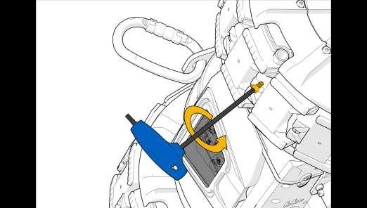
Screw carefully until resistance is met. Do not use excessive force.
center pins before screwing.
Hole in pin must be visible through bushing. Pin must be locked by screw.
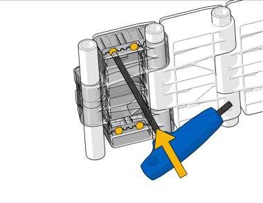
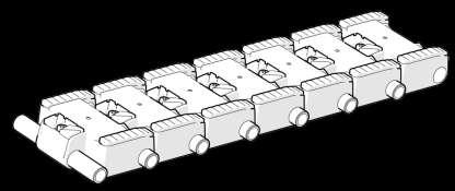
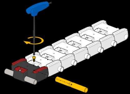
Maintenance - Replace Rubber Pads or Magnetic Tracks
Remove center screw that locks the damaged magnetic track.
Remove center axle that locks the damaged magnetic track.
Maintenance - Replace Rubber Pads or Magnetic Tracks
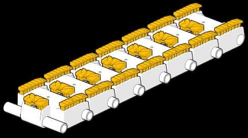
Reassemble belt. Remember to center pin in track before mounting.
Replace magnetic track. See page 112 for refitting belt
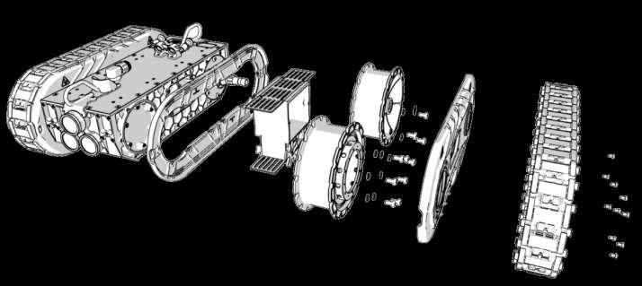
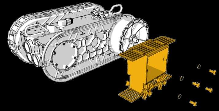
Complete side
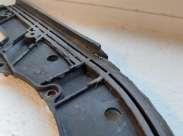
The entire side mechanics is divided into large subassemblies, which can be removed separately. To access the detailed assembly of the sub-assemblies, the QR-codes in this section can be scanned. To access the enitre assembly of the side, the QR code below can be scanned.
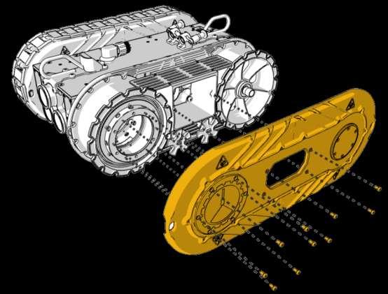
Side plate assembly
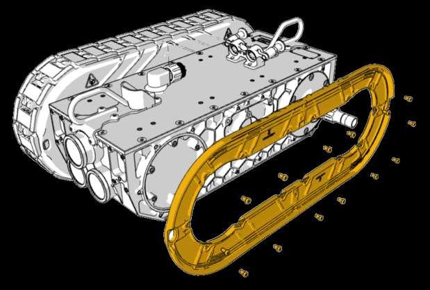
Remove entire side assembly in one piece, to enable exchange of screens.
To access detailed assembly of the side plate assembly [MA00110] please scan the QR-code.
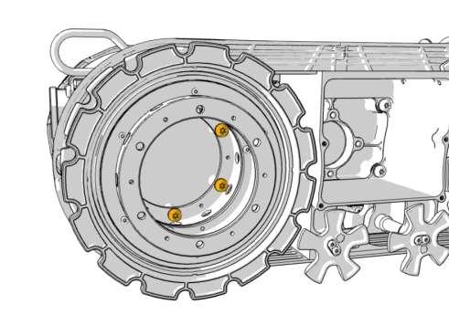
Complete side
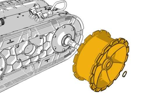
Identify the M8 screws inside the free wheel. x6
assembly
Remove entire free wheel assembly. To access detailed assembly of the free wheel assembly [MA00103]
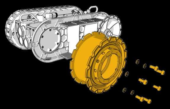
Remove entire track bearing assembly.
To access detailed assembly of the track bearing assembly [MA00108] please scan the QR-code.
MA00108 Track bearing assembly
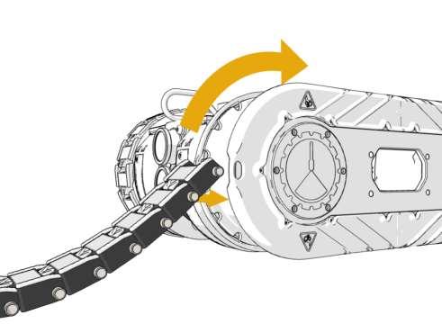
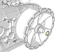
Remove the circlip and remove the drive wheel from the drive wheel shaft.
M000943 Track Screen
Mount Belt 1
Drive slow
Mount magnetic belt at a drive wheel. Insert pin in front magnetic track and drive carefully with control box. Please note that two crew members are required for this job. Be careful to fit the magnetic track pins on both wheels.
track
Align steering wheel to avoid damage of track screens when mounting the magnetic belt.
x4
Drive slow
Mount Belt
When magnetic belt is mounted, the last pin should be replaced to lock the belt. Maintenance
Insert MFA0071 screw to lock the belt. Make sure to center the track pin.
Tighten the screw firmly with MTO0002 - Do not overtighten.