This is the manual for the High-pressure System. The manual contains instructions in safety, transportation, storage, preparation for use and maintenance.
The manual for the In-line Heater is a separate manual.
Read the safety instructions in this document carefully.
Read all documentation before first use.
CLIIN Robotics disclaims all liability for injury and damage to people
and/or property caused by non-compliance with instruction requirements and the contents of this manual.
• High-pressure water jet.
• Never aim the water jet at yourself, people, animals or the machine itself.
• Incorrect installation and use may result in serious damage or injury.
• Do not under any circumstances tamper with or adjust the safety valve.
• Any warranty of the system will be waived if the safety valve has been tampered with.
• Sub-zero temperatures can result in equipment rupture and will damage the High-pressure System.
• Never use the High-pressure System in sub-zero temperatures (i.e. below 0 °C (32 °F)).
• The High-pressure System should always be stored in a frost proof place, if this is not possible, the machine must be frost protected as described in this manual.
• Any damage caused by the use or storage of the High-pressure System in sub-zero temperatures (i.e. below 0 °C (32 °F)) will not be covered by any warranty of the system.
High-pressure System - Safety
• Keep away from children and animals.
• Do not spray on electrical wiring or installations.
• Avoid spraying on fragile surfaces and facilities.
• Never pull the High-pressure System power or communication cables as this may result in damage to the system and lead to potentially dangerous situations.
• Only use potable or technical fresh water as working medium.
• Do not add cleaning agents to the working medium.
• Never drink the water used in the High-pressure System even though tap water is used as medium.
• Use wheel chocks to keep the High-pressure System stationary. At sloped or potentially rolling decks additional securing by lashing is required.
• No modification must be made to the High-pressure System without the expressed written consent of CLIIN Robotics.
• Do not leave the High-pressure System unattended in operation.
• Any warranty of the system will be waived if proper maintenance is not performed as described in this manual at the given intervals.
• Always wear proper personal protective equipment (PPE).
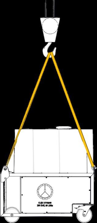
• Only trained and qualified personnel must perform lifts.
• Plan the lift and lifting route before execution, to minimise the risk of accidents.
• Only use approved equipment for lifting.
• Only use the four (4) dedicated pad eyes for lifting.
• Never stand underneath objects being lifted.
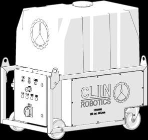
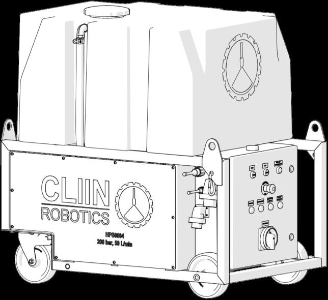
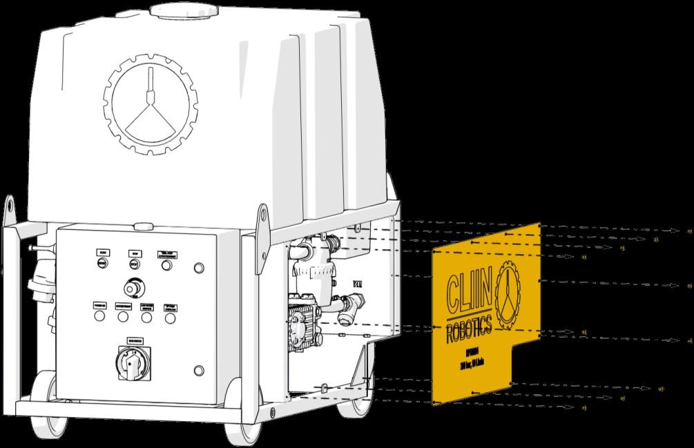
High
HPS0004/-5
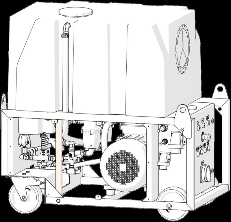
High-pressure system
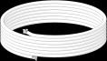
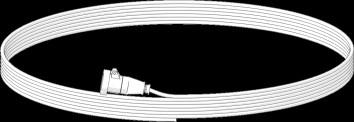
M000494 2 m, lance for hatch coamings
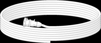
M000217
hose
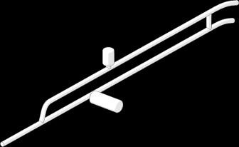
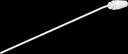
Double-barreled highpressure lance with handle and flat jet nozzle
MA00049
High-pressure lance for removal of rust and loose paint
MA00050 Gun for lances
M000475
Cover for High-pressure System
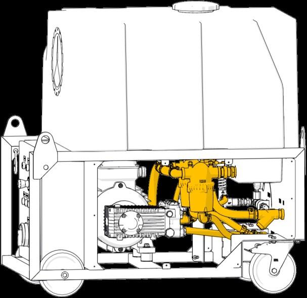
High-pressure System - Specifications
Voltage (robot/pump)
Frequency
Current (robot/pump)
V / 380-440 V
Hz
A / 32 A
400 V connection 3 poles + earth, 3H
110/230 V connection 2 poles + earth, 6H
Working pressure (non adjustable)
Flowrate @ 50 Hz
Flowrate @ 60 Hz
Working
bar (2,900 psi)
l/min (10.8 US gal/min)
l/min (13.1 US gal/min)
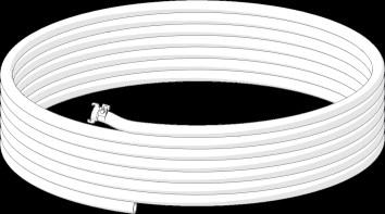
Before First Installation - Freshwater Hose
OD: 33 mm (1.3”)
ID: 25 mm (1”)
A coupling for the freshwater installation must be fitted to the open end of the freshwater hose before the hose can be used. The coupling must fit the above measurements and withstand a pressure of min. 6 bar (87 psi) at 40 °C (104 °F).
Freshwater hose
Before First Installation - Electrical Cables
Below installation must be performed by an authorised electrician.
400 V electric cable - 4 cores @ 6 mm2
Voltage rating: 380-440 V Current rating: 32 A
A 400 V power plug to fit the electrical installation must be fitted to the open end of the 400 V cable before the cable can be used. The plug must comply with applicable legislation and the specifications above.
230 V electric cable - 3 cores @ 1.5 mm2
Voltage rating: 200 - 240 V Current rating: 16 A
A 230 V power plug to fit the vessel electrical installation must be fitted to the open end of the 230 V cable before the cable can be used. The plug must comply with applicable legislation and the specifications above.
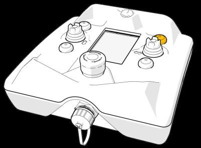
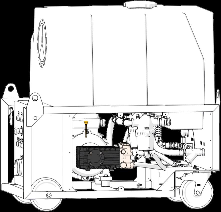
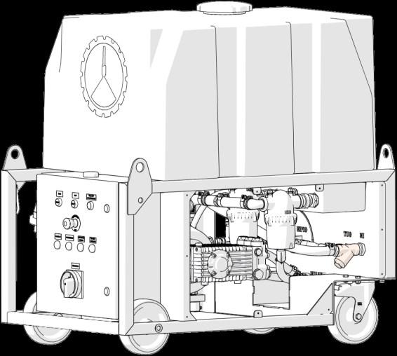
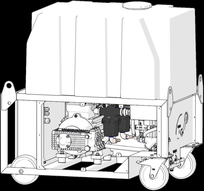
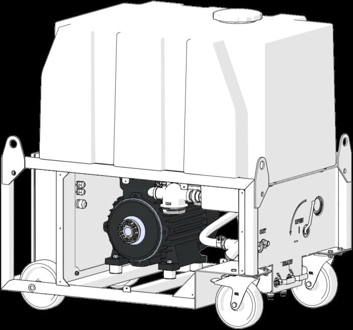
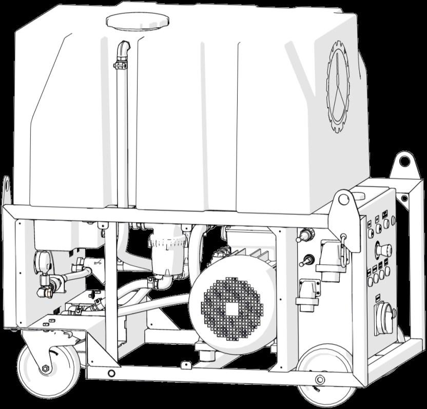
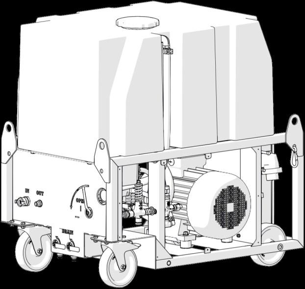
High-pressure System -
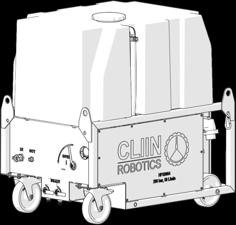
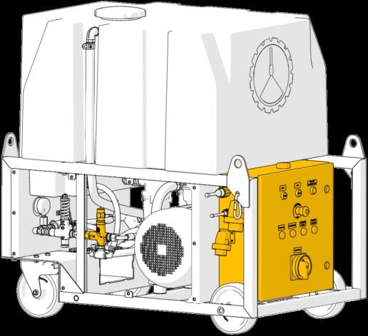
Lockable wheels x2
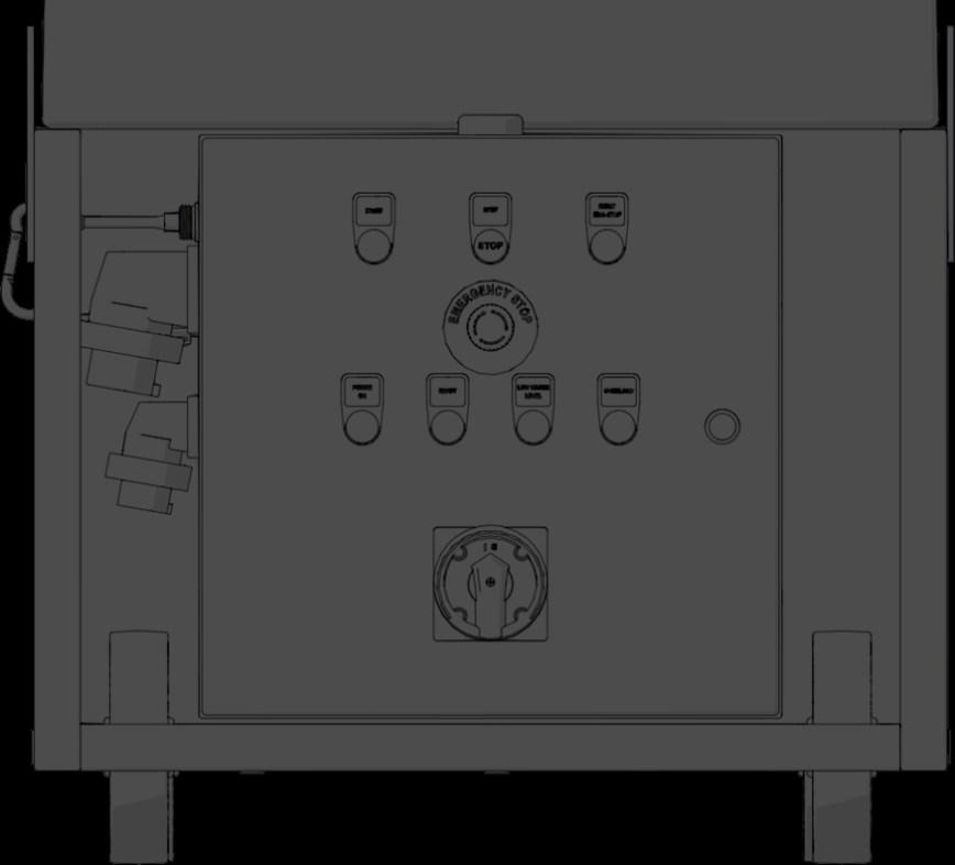
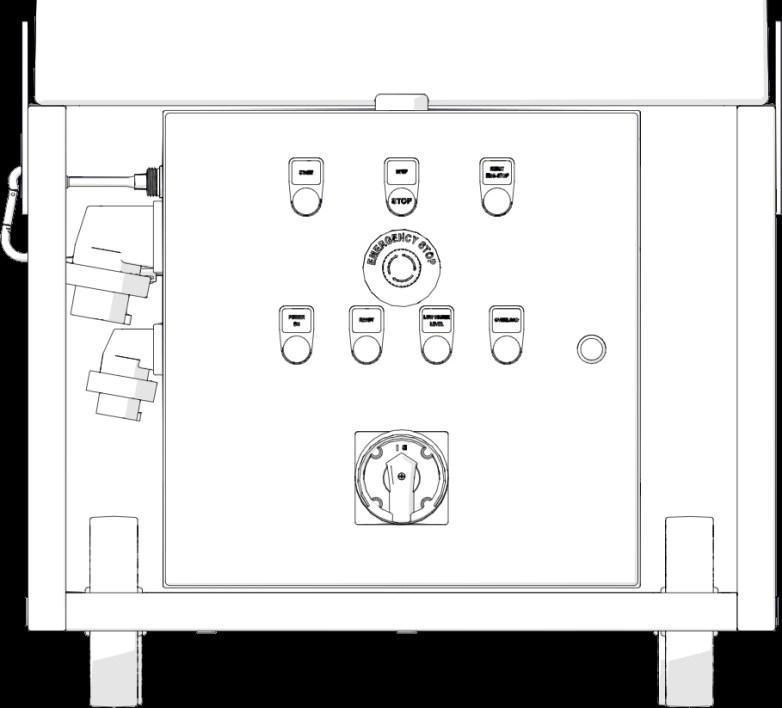
Control panel
For control and surveillance of the High-pressure System.
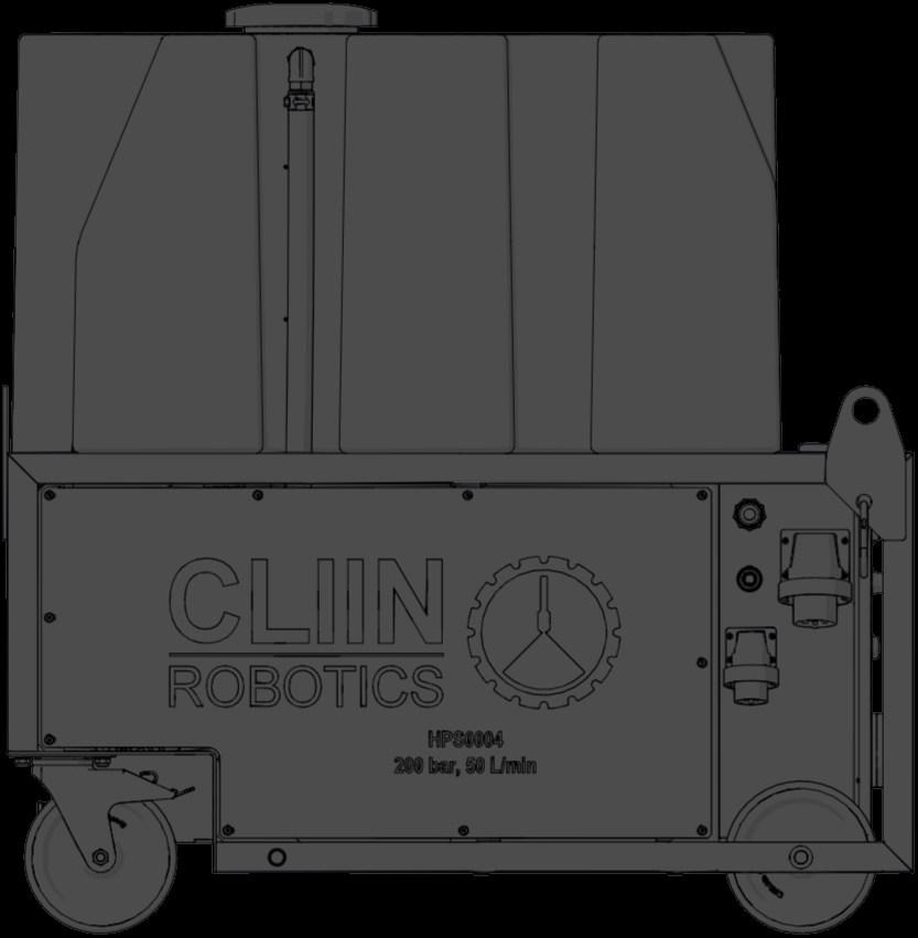
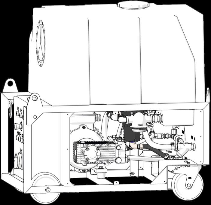
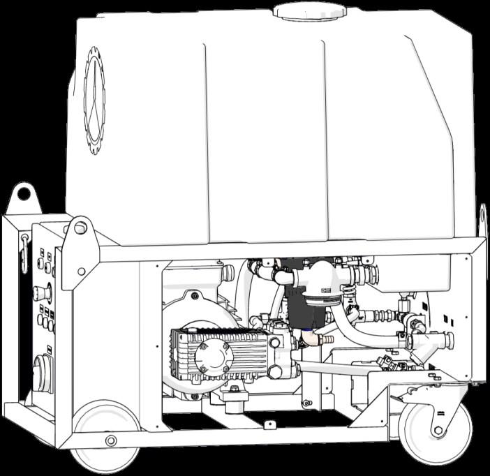
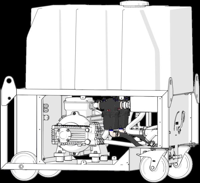
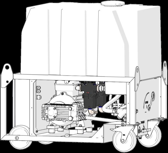
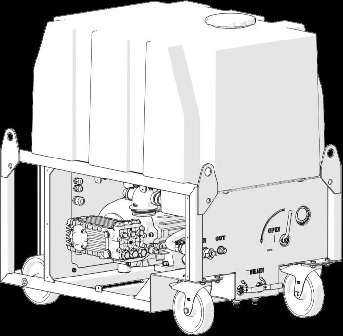
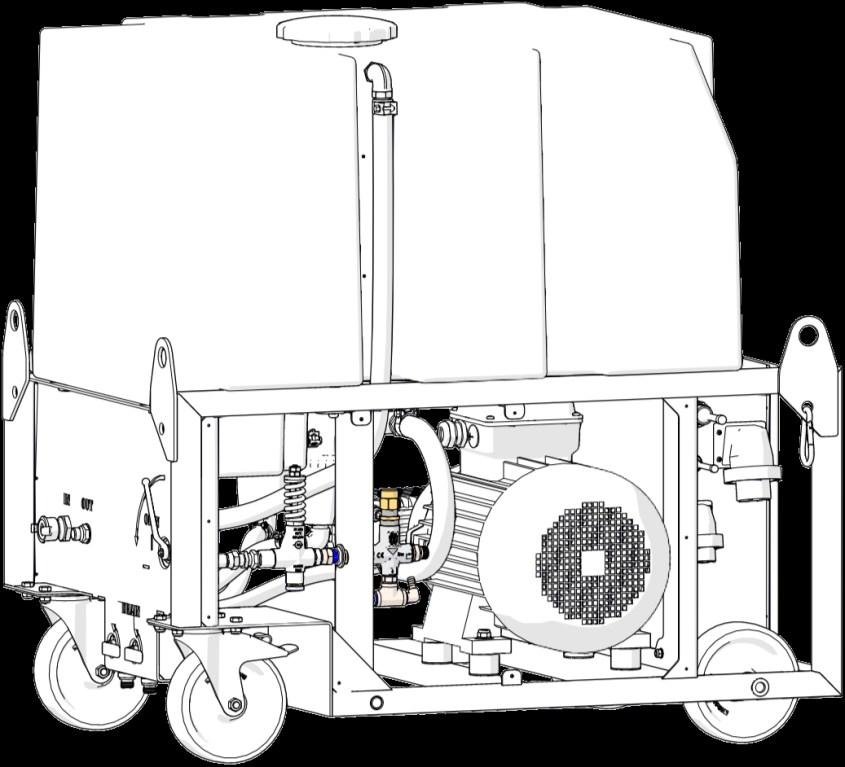
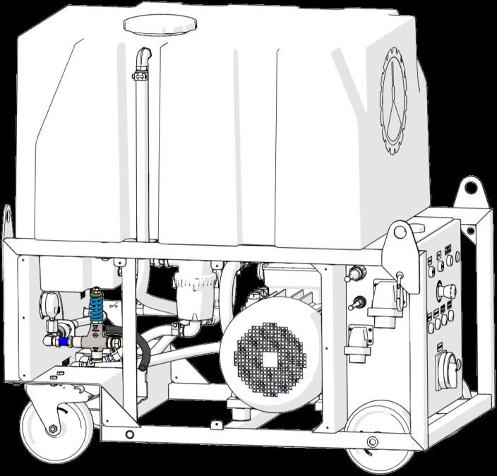
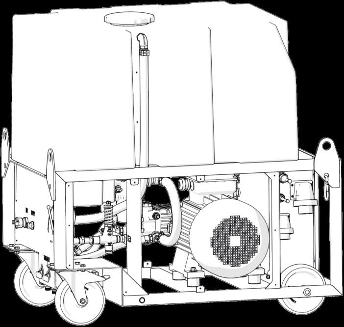
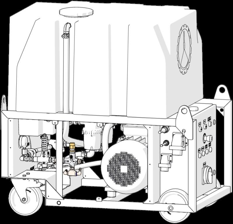
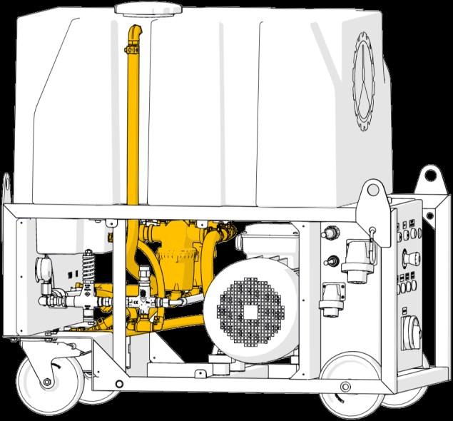
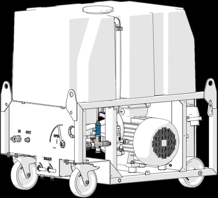
High-pressure System - Overview
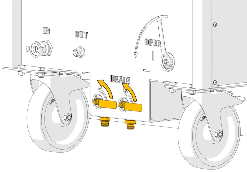
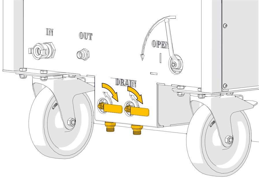
Drains
For draining water from the system after usage. The left drain flushes the filter.
For securing communication cables.
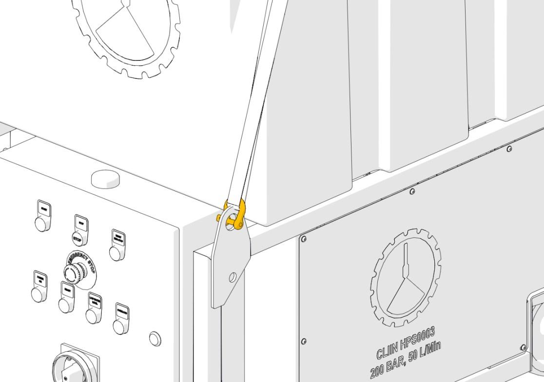
Lifting pads x4
Carabiner
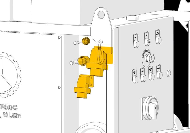
High-pressure outlet
G1/2”.
Freshwater inlet
GEKA claw coupling.
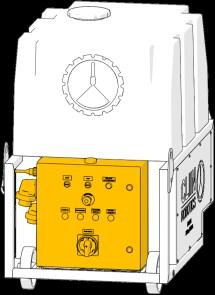
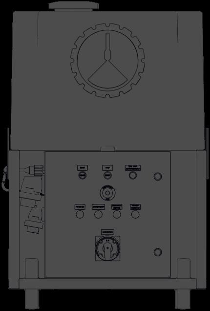
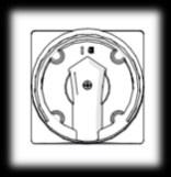
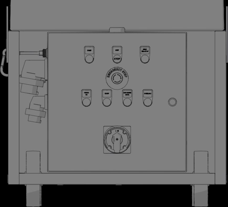
High-pressure System - Overview, Control Panel
Further information is found in the Robot manual.
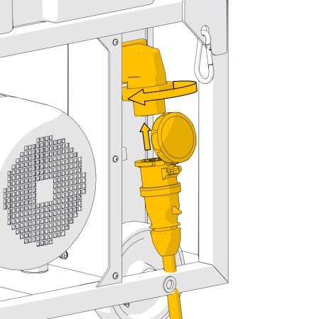
Hybrid cable connection
Signal cable connection
230 V power inlet connection
400 V power inlet connection
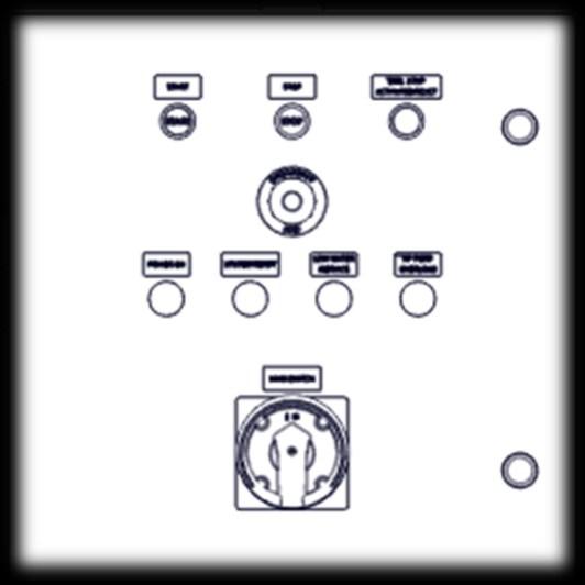
High-pressure System - Overview, Emergency Button
Emergency buttons
Press the emergency button in the case of an emergency or if an unexpected situation occurs. The button “EMG. STOP ACTIVATED/RESET” will illuminate to indicate emergency mode.
The emergency buttons do not shut down the In-line heater if such is used. Use the switches on the In-line Heater.
The In-line Heater burner will, however, pause when the water supply is stopped.
Control box emergency button
The control box emergency button is ONLY functional when all the following criteria are met:
• Control box connected to the High-pressure System.
• Robot connected to the High-pressure System.
• 230 V power connected to the High-pressure System.
High-pressure System - Overview, Emergency Button
1. Release the emergency button by
Before releasing the emergency button, investigate why the button was pressed and assess the situation. When the situation is safe the emergency button can be released. Reset the system by pressing the “EMG.
” button on the
High-pressure System - Overview, Controls
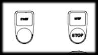
START
Press the “START” button to activate the pump.
A short delay must be expected before the pump is at full capacity.
Main switch
Switches the 400 V power ON/OFF.
STOP
Press the “STOP” button to deactivate the pump.
High-pressure System - Overview, Controls
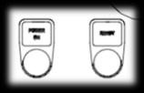
Control box
The pump can be started/stopped remotely on the control box.
• Start: Press and hold the water button (2 seconds) to activate the pump.
• Stop: Press the water button to deactivate the pump.
The control box is only functional when all the following criteria are met:
• Control box connected to the High-pressure System.
• Robot connected to the High-pressure System.
• 230 V power connected to the High-pressure System.
High-pressure System - Overview, Status Indicators
POWER ON
SYSTEM READY
The “SYSTEM READY” indicator illuminates green when all the following criteria are met:
• Sufficient water in the tank.
• Emergency mode not triggered.
• No overload detected on the system.
• Temperature is within system specification.
The “POWER ON” indicator illuminates white when all the following criteria are met:
• 400 V power is connected to the High-pressure System.
• Main switch is in the ON position.
• DC circuit breaker not tripped.
High-pressure System
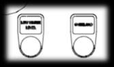
LOW WATER / SERVICE (continuous / flashing)
• Continuous: The “LOW WATER / SERVICE” indicator illuminates yellow when there is insufficient water in the tank.
• 2 flashes: The “LOW WATER / SERVICE” indicator flashes twice yellow when service is needed. Service indication does not affect the function of the High -pressure System.
• 3 flashes: The “LOW WATER / SERVICE” indicator flashes three times yellow when the water reaches freezing temperatures (i.e., below 2 °C). The Highpressure System will shut down.
HP PUMP OVERLOAD
• 4 flashes: The “LOW WATER / SERVICE” indicator flashes four times yellow when the water reaches high temperatures (i.e., above 40 °C). The Highpressure System will shut down. Information regarding service is found in the maintenance chapter.
The “HP PUMP OVERLOAD” indicator illuminates yellow when one of the following failures are detected:
• Overload
• Overtemperature
• Phase loss
• Phase imbalance
Storage & Handling - Lifting the High-pressure System
• Only trained and qualified personnel must perform lifts.
• Always use proper PPE.
• Plan the lift and lifting route before execution, to minimise the risk of accidents. Only use approved equipment for lifting. Inspect the four lifting plates for any damage or extensive wear before attaching the lifting equipment. Chains/slings must have a minimum length of 2 meters from the system to the connection point. This is to avoid damage to the system.
Never stand underneath objects being lifted.
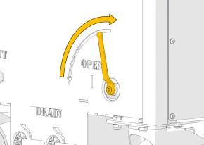
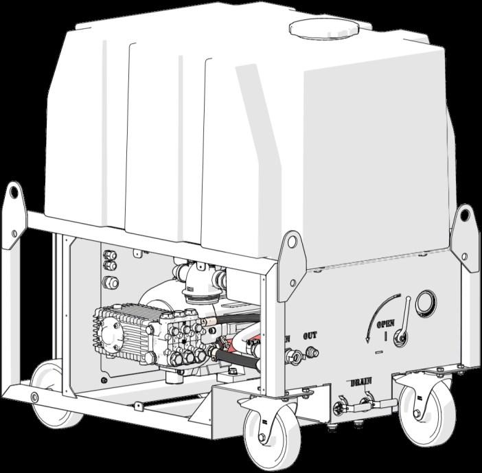
the system must be drained before lifting.
To drain the system open the two drain valves by placing both handles in the vertical position.
System weight: 285 kg (630 lb)
Min. Length: 2 m (6.5 feet)
1. Stop the system by pressing the stop button.
2. Turn the main switch to the OFF position.
3. Activate the gun, if such is installed, to release the pressure.
Stop the water supply going into the system.
The water supply can be shut off 8 min before end of use to reduce water waste.
Close the high-pressure valve (vertical position).
Disconnect all hoses.
Take care not to damage threads and fittings.
Drain the system by opening the two drain valves (vertical position).
When the system is empty close the drain valves again (horizontal position).
Do not move the system when not empty. The total weight of the system with a full tank is approximately 685 kg (1500 lb).
Storage & Handling - Storage
protection plugs
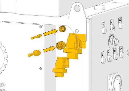
Disconnect all cables. Do not pull the cables but grab the plug itself to avoid damage.
Place the protection plugs on the signal and hybrid connections. Remember lubrication.
Close and lock the caps on the electrical
Further information on protection the signal and hybrid cables is found in the Robot manual.
Do not store the system in sub-zero conditions without frost protection. x2
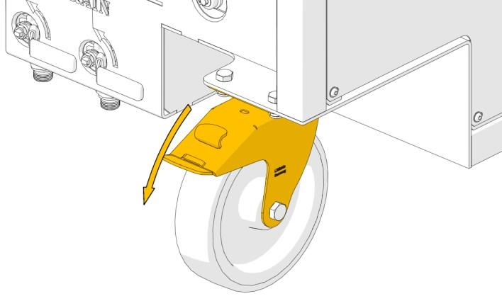
Move the High-pressure System to the storage position.
When the system is in place lock the two back wheels. Preferably use wheel chocks to further secure the system during storage.
Take special care, when moving the system, if the vessel is in transit.
hose
The main hose can advantageously be disassembled half way for easier handling.
Take care not to damage threads/fittings.
Main
Storage & Handling - Storage
• For easier handling, drain water from the hoses before storage. Can easily be done with an airgun.
• Anti-seize paste can be used on the stainless steel threads to ease the disassembly.
• General cleaning before storage will prolong the life time of the equipment.
• Use the High-pressure System Cover (M000475) for extra protection during storage.
Never store equipment in splash zones on vessels - e.g forecastle area.
- Avoid splash from waves and heavy weather.
Storage & Handling - Storage in Cold Conditions
• Sub-zero temperatures can result in equipment rupture and will damage the High-pressure System.
• It is highly recommended to store the High-pressure System in frost-free conditions. If this is not possible, the system must be frost protected.
• Any damage caused by the use or storage of the High-pressure System in sub-zero temperatures (i.e. below 0 °C (32 °F)) will not be covered by any warranty of the system.
Dismount all hoses from the High-pressure System. Drain the water from all hoses. pressure valve (horizontal position).
Drain the system by opening the two drain valves
When the System is empty close both drains again
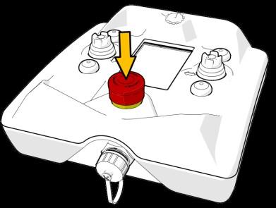
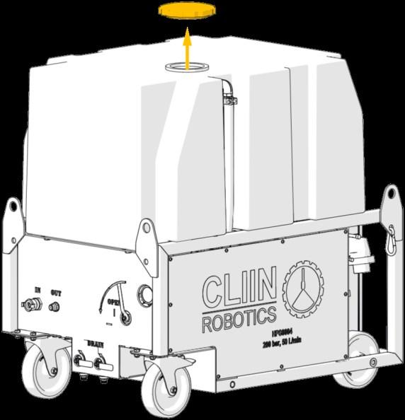
Remove the lid from the tank.
Fill 20 l (5.3 US gal) of glycol (40/60) into the tank.
Storage & Handling - Storage in Cold Conditions
9. Force-start the system by pressing and holding the start button for 20 seconds. The force-start have a 10 seconds delay. The system will then run for 10 seconds if the start button is not released before.
10. Repeat step 9 until glycol is beginning to exit the high-pressure outlet.
11. Stop the system by releasing the start button.
12. Close the high-pressure valve (vertical position).
13. Force-start the system again to mix the glycol with the last remaining water in the system. Let the system run till it stops by it self (10 seconds).
With correct frost protection the High-pressure System can be stored in temperatures down to -10 °C (14 °F).
Prepare System for Use
Close both drains to avoid wasting water.
The system will not function correctly with the drains open.
If positioned on an inclined or moving surface (e.g. vessel during transit) use lashes for securing the High-pressure System to a x2 1 - 2 1 2
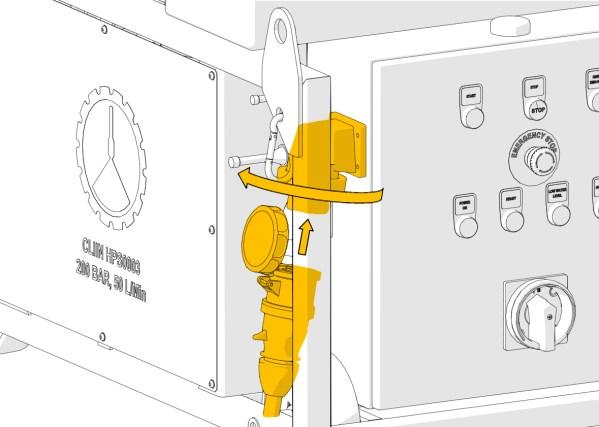
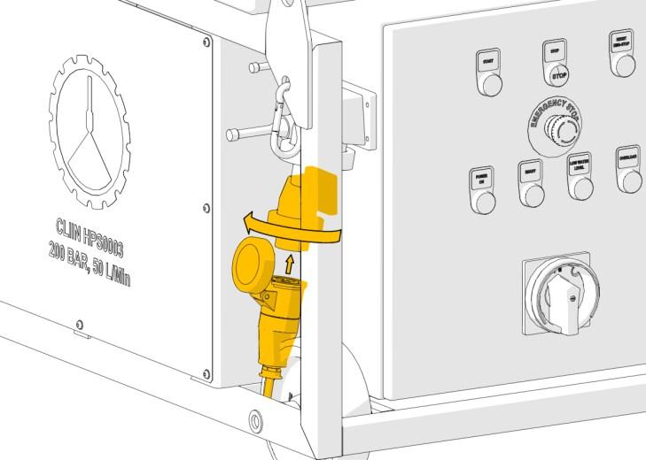
Before connecting any equipment to the High-pressure System, find a suitable place for it and lock the wheels.
Visually check the High-pressure System for any damage inflicted during storage or transport. Focus on the highlighted areas.
Freshwater hose x2 4 4 - 5 5
• Inspect the entire length of both hoses for damage before use.
• Check and clean threads and seals for dirt.
• Anti-seize paste can be used on the stainless steel thread to ease the disassembly.
Assemble the main hose if disassembled. Must be tightened thoroughly before use.
Main hose
400 V electric cable
230 V electric cable
• Go through the entire length of both the electric cables for damage before use. If the insulation is breached the cables must be changed.
• Visually check the plugs in both ends for damage.
• Check and clean the plugs for dirt.
Visually check the pistol and lances for damage.
Prepare System for Use - Power Connection
Voltage rating: 240 V 8 - 9 8 9
Connect the 400 V cable to the vessel power supply and the control panel left side. Secure the plug with the collar.
Current rating: 32 A
Voltage rating: 380 - 440 V
Information on connecting the Robot and control box is found in the designated manual.
Connect the 230 V cable to the vessel power supply and the control panel left side. Secure the plug with the collar.
Current rating: 16 A
Prepare System for Use - Power Connection
• Cleaning without the Robot, only requires 400 V power supply.
• For operating the High-pressure System by the use of the control box, 230 V power supply and Robot must be connected.
The emergency button on the control box will be disabled.
Prepare System for Use -
Before connecting the freshwater hose to the vessel freshwater supply, open the supply to let any debris out.
This is to protect the High-pressure System against clogging and consequently pressure loss, cavitation and internal damage.
• Water supply must be clean freshwater. The use of other fluids as working medium may damage the system.
• When using poor quality water the system will be subject to high wear and frequently filter clogging.
• Water supply pressure must not exceed 6 bar (85 psi).
• Water supply temperature must not exceed 40 °C (104 °F).
11 - 13 11-13
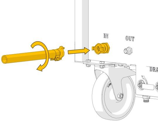
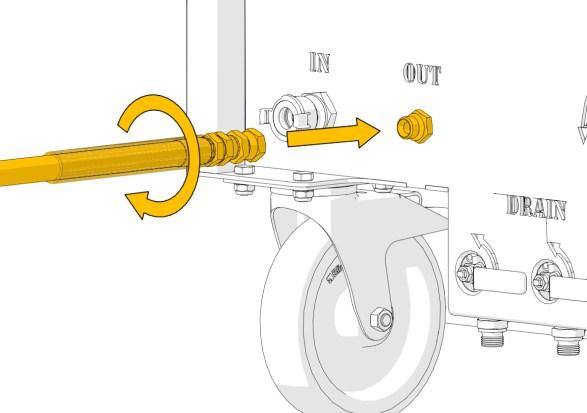
• Connect the freshwater hose to the vessel freshwater supply and the inlet connection on the back side of the High-pressure System.
• Make sure there are no twists and sharp bends on the hose.
• Open the water supply to fill the tank.
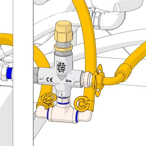
Prepare System for Use - High-pressure Connection
Connect the high-pressure hose to the system output connection. Tighten thoroughly before use.
• Further information on connecting the Robot is found in the designated manual.
• Information regarding cleaning at elevated temperatures and connecting the In-line Heater is found in the designated manual.
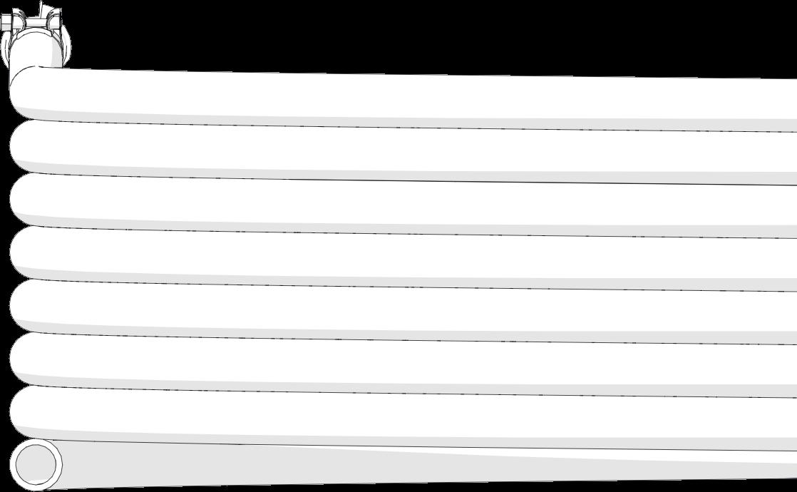
The first 12.5 meters (41 feet) of the high pressure hose is strengthened by a plastic hose
Make sure to place the strengthened part pressure hose where sharp edges are found (e.g. hatch coamings).
This can prevent damage to the high Hose protection
Before connecting the high-pressure hoses to the highpressure equipment flush the hose for 15-30 seconds. This is to remove dirt and debris within the hose and connections. This will reduce the wear and malfunction of the nozzles.
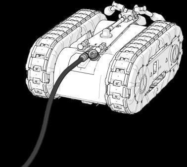
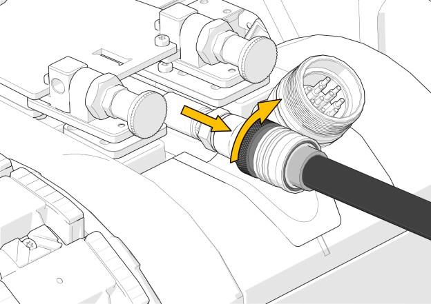
Prepare System for Use - Robot Connection
17
Connect high-pressure hose to the highpressure tool on the Robot.
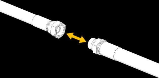
18
Always lock the high-pressure coupling.
Press the collar towards the hose and turn it either way to secure it.
Further information on connecting the Robot, cleaning tool etc. is found in the designated manual.
17 - 18
Robot with highpressure tool installed.
17-18
17 - 18 17 - 19
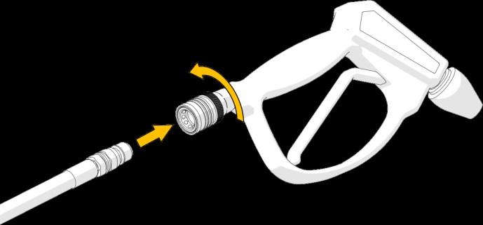
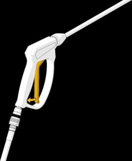
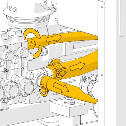
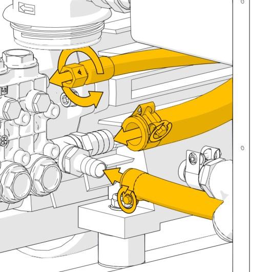
• Connect the high-pressure hose to the pistol.
Always lock the highwards the hose and turn it either way to secure it.
Connect the pistol to the desired lance.
Main hose
Prepare System for Use - Robot Connection
• Go through the preparation steps before continuing with operation.
• Make sure the output end of the high-pressure hose is under control before starting the High-pressure System to avoid injury and damage to personnel and equipment.
• Remove any equipment that cannot withstand cleaning by high-pressure water.
• Never aim the water jet at yourself, people, animals or the machine itself.
• Do not spray on electrical wiring or installations.
• Avoid spraying on fragile surfaces and facilities.
• Do not leave the High-pressure System unattended in operation. Turn OFF the main switch before leaving.
• When leaving the High-pressure system close the high-pressure valve to reduce water wastage.
Start the system by pressing the start button.
-
Wait 5 - 10 seconds then press the stop button. 7
8
• When water is flowing consistently normal operation can begin.
• If water was not running consistently wait 10 seconds before repeating step 6 and 7 again. If inconsistent water flow continues make sure the high-pressure valve and/or gun are open. Otherwise, refer to the trouble shooting scheme, “No water is coming from the output - Air in the system”.
• When the start-up procedure is completed, normal operation can begin.
• The High-pressure System can be started and stopped as needed.
• If the water level in the tank becomes critical the system will automatically stop. Once the water level is above minimum, the High-pressure System can be restarted.
Activate the gun, if such is installed, to release pressure.
2
3 1 - 3
Refer to the “preparation - storage” chapter for the further process of preparing the High-pressure System for storage.
Always store the High-pressure System in a frost-free place. If not possible refer to the “preparation - storage in cold conditions” chapter.
• Only trained personnel and authorised electricians are allowed to operate within the control panel.
• No modification must be made to the High-pressure System without the express written consent from CLIIN Robotics.
• Under no circumstances tamper with or adjust the safety valve.
• Any warranty of the system will be waived if the mentioned restrictions are not met.
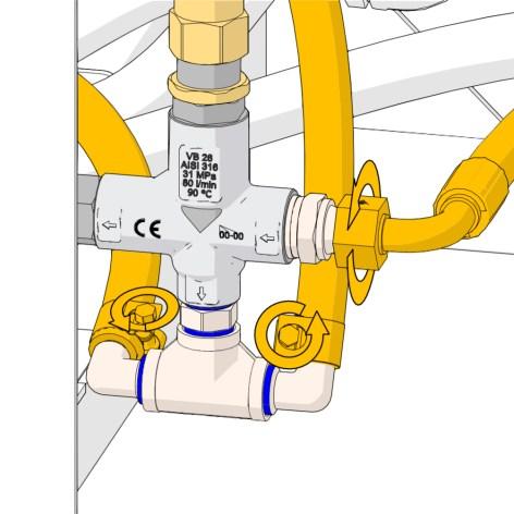
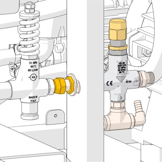
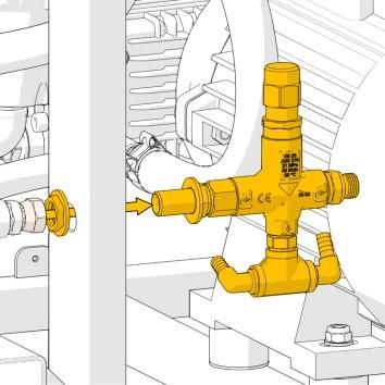
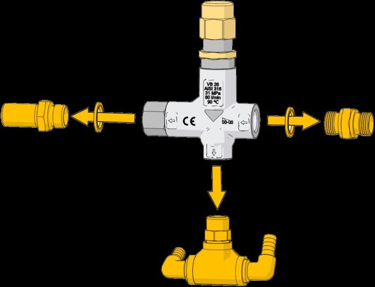
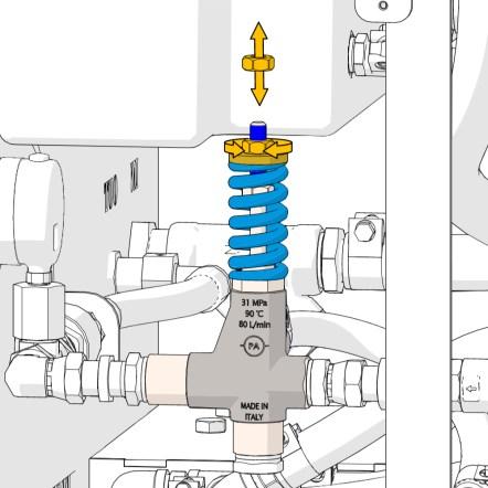
Safety valve.
Control panel.
Troubleshooting
“HP PUMP OVERLOAD” status indicator is illuminated
Possible cause: Solution:
Circuit breaker (-Q02) in OFF position. 1. Disconnect power.
2. Within the control panel check position of the circuit breaker (-Q02).
3. If the knob is in the “OFF” position, turn the knob to the “ON” position.
2. Within the control panel check position of the circuit breaker (-Q02).
Soft Starter (-U01) fault/ overload.
3. If the knob is in the “TRIPPED” position. Contact CLIIN Robotics for instructions.
4. To reset, turn the knob to the “OFF” position then to the “ON” position.
1. Within the control panel locate the soft starter (-U01).
2. The fault will be displayed by the number of flashes from the small red light on the soft starter.
3. Contact
4. To reset, hold the reset button until the small red light stops flashing or turn the main switch OFF then
Troubleshooting
LOW WATER/SERVICE status indicator is illuminated (continuously)
Possible cause: Solution:
Water level in the tank is low. Fill the tank with water.
LOW WATER/SERVICE status indicator is illuminated (continuously) with a full tank
Possible cause: Solution:
Defect water level detection. Contact CLIIN Robotics for troubleshooting and/or water level switch replacement.
2
3
LOW WATER/SERVICE indicator is flashing
Possible cause: Solution:
Service is required (2 flashes). The “LOW WATER/SERVICE” indicator will start flashing when service is needed. 2 flashes followed by a pause indicates service. The PLC within the control panel will inform of the specific service needed. Further information is found in the “Service” section of this chapter.
4
Troubleshooting
LOW WATER/SERVICE indicator is flashing
Possible cause: Solution:
Water temperature is too low (3 flashes).
Water temperature is too high (4 flashes).
When the water temperature in the tank gets below 2 °C (35.6 °F) the pump will stop to protect the system against frost damage. The “LOW WATER/SERVICE”
indicator will flash 3 times followed by a pause.
The High-pressure System can be started again when the temperature raises above the aforementioned level and the power has been cycled.
To bypass the protective measures, contact CLIIN. Any warranty will be void when bypassing the frost protection.
When the water temperature in the tank gets above 40 °C (104 °F) the pump will stop to protect the system against damage. The “LOW WATER/SERVICE”
indicator will flash 4 times followed by a pause.
The High-pressure System can be started again when the temperature falls below the aforementioned level and the power has been cycled.
To bypass the protective measures, contact CLIIN. Any warranty will be void when bypassing the protection.
Troubleshooting
No water is coming from the output
Possible cause: Solution:
High-pressure valve closed or partly opened.
Air in the system.
Clogged filters.
Make sure the high-pressure valve is completely open (horizontal) to allow water free passage from the pump.
1. Stop the pump.
2. Make sure there is water in tank.
3. Make sure the high-pressure valve is open.
4. Disconnect the main hose from the high-pressure output.
5. Start the High-pressure System and let it run for 5-10 seconds and stop it again.
6. If water is not running consistently wait for 10 seconds and repeat step 5.
7. When water is running regularly, reattach the main hose again and continue work.
1. Open the right drain valve and keep in open for 30 seconds to flush the filters.
2. If this does not help, clean the filters. Further information is found in the “Service” section of this manual.
Troubleshooting
Pump is making inconsistent/high noise
Possible cause: Solution:
Drain valve(s) open. Close both drain valves.
Air in the system. See troubleshooting no. 5 under “Air in the system”.
Level switch defect. Low/no water.
If the pump keeps running with no water in the tank. Stop the pump immediately to avoid damage to the pump.
The system can continue operation when the tank is filled. However, personnel MUST manually monitor the water level to stop the system before it runs dry and damage the pump.
Contact CLIIN for troubleshooting and/or level switch replacement.
Clogged filters. Clean the filters. Further information is found in the “Service” section of this manual.
Leaky low-pressure system. Stop the pump and make sure there is water in the tank.
Check for water leaks around the filter, drains and the hoses connecting. Contact CLIIN for further troubleshooting.
Troubleshooting System does not provide necessary pressure
Possible cause: Solution:
High –pressure valve closed or partly opened.
Make sure the high-pressure valve is completely open (horizontal) to allow water free passage from the pump.
Loose/leaky connection. Tighten leaky connections on high-pressure part of the system.
Leaky hoses.
Check hoses, fittings and high-pressure tools for leaks.
Contact CLIIN if replacement is necessary.
Hose is pinched or twisted. Straighten the hoses and make sure no equipment is placed on top of the hoses.
Running 50 Hz with too large nozzles.
Worn nozzles.
Change the high-pressure tool to fit the flow from the pump.
Worn nozzles will show as decreased pressure. Contact CLIIN for replacement.
Pressure regulator valve clogged. Contact CLIIN for instructions.
Pump valves dirty or worn (pulsating).
Level switch defect. Low/no water.
High-pressure system frost damaged/leaky.
1000 hours service needed. Further information is found in the ”Service” section of this chapter.
See troubleshooting no. 6 under “Level switch defect”.
Look for dripping/running water under the high-pressure part of the system. Contact CLIIN for instructions.
Troubleshooting
System does not provide necessary pressure
Possible cause: Solution:
Pump cavitation. See troubleshooting no. 6.
Worn/incorrectly adjusted pressure regulator.
7
Pressure setting should read 190-195 bar on the pressure gauge. Prior to valve adjustment check the pressure by using the double-barreled lance (see step 83 through 85 in the 1000 hours service). To adjust the pressure follow the steps 83 through 89 in the 1000 hours service section of this manual.
System does not start/power up
Possible cause: Solution:
Missing power.
Dirty power plug.
8
Connect the power cables. Turn the main switch ON.
Clean the power plugs.
Emergency button triggered. The control button “EMG. STOP ACTIVATED/RESET” will illuminate.
1. Investigate why the emergency button was activated.
2. Assess the situation.
3. When the situation is safe, deactivate the emergency button and reset.
Fuse (-F01) tripped. On the control panel, turn the main switch ON. If the status indicator “POWER ON” does not illuminate, check the fuse (-F01) within the control panel.
Motor protection tripped. The status indicator “HP PUMP OVERLOAD” will illuminate. See troubleshooting no. 1.
Troubleshooting
System does not start/power up
Possible cause: Solution:
Low water. The status indicator “LOW WATER/SERVICE” will illuminate (continuously). Fill the tank with water.
Level switch stuck/defect. The status indicator “LOW WATER/SERVICE” will illuminate (continuously) even though the tank is filled with water. Contact CLIIN for instructions. 8
“SYSTEM READY” status indicator does not activate
Possible cause:
Emergency button activated.
Solution:
1. Investigate why the emergency button is activated.
2. Assess the situation.
9
3. When the situation is safe, deactivate the emergency button and reset.
Low water. The status indicator “LOW WATER/SERVICE” will illuminate continuously. Fill the tank with water.
HP Pump overload. See troubleshooting no. 1.
Troubleshooting
Water is overflowing the tank
Possible cause: Solution:
Too high inlet pressure. Max of 6 bar (85 psi) inlet pressure. The float valve cannot adequately close the water flow at higher pressure.
Float valve stuck in open position. Open the tank lid to check if the lever arm of the float valve is not raised against the tank top. If so, gently jerk the lever arm up and down to loosen the arm.
Float valve container is water filled. The float has been punctured and does not have the ability to adequately close the water flow. Contact CLIIN for replacement.
Troubleshooting
Water is not flowing into the tank
Possible cause: Solution:
No water supply. Check that the water supply is open and hoses connected correctly.
Inlet hose is pinched or twisted. Straighten the hoses and make sure no equipment is placed on top of the hoses.
Float valve stuck in closed position. Open the tank lid to check if the lever arm of the float valve is raised against the tank top. If so, gently jerk the lever arm up and down to loosen the arm.
Float valve is clogged. Open the tank lid. Gently jerk the lever arm up and down to loosen any debris within the valve. Contact CLIIN for further troubleshooting.
Inlet Y-strainer is clogged. Empty and clean the Y-strainer placed on the inlet water line within the Highpressure System.
Service - Introduction
LOW WATER / SERVICE (flashing)
The “LOW WATER/SERVICE” status indicator starts flashing (2 flashes) when service is required. Service is required at the following intervals:
• After the first 50 motor hours.
• Every 500 motor hours.
• Every 1000 motor hours.
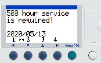
Open the control panel and locate the PLC which will inform of the required service needed.
Needed kits and special tools can be ordered at CLIIN before commencing the service. Consult the maintenance chart or contact CLIIN for correct order.
The 50 hour and 500 hour service are the same.
1 - 2
2
Open the tank lid and wash down any dirt and debris on inside of the tank.
Take care not to damage the float valve.
Do not use high pressure cleaning.
Dismount the right side panel.
4.Remount the drain plug (40 Nm). Remove the oil dipstick 4 5 4 - 5
1.Place a container under the pump to collect the oil.
2.remove the drain plug.
3.wait for the oil to drain.
Remount the oil dip stick by hand. 7
Pump oil - SAE 15W/40 6
Fill in oil to the middle of the oil gauge window (≈ 1 litre).
The oil is slow flowing, give it a minute to settle before reading the gauge window.
Be careful not to damage the seal. 8 8 - 10
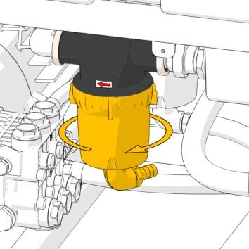
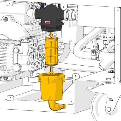
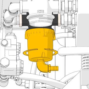
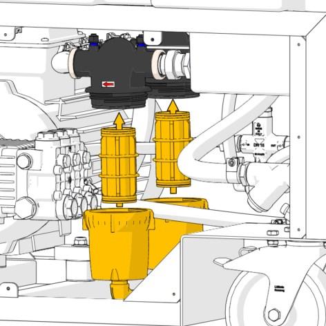
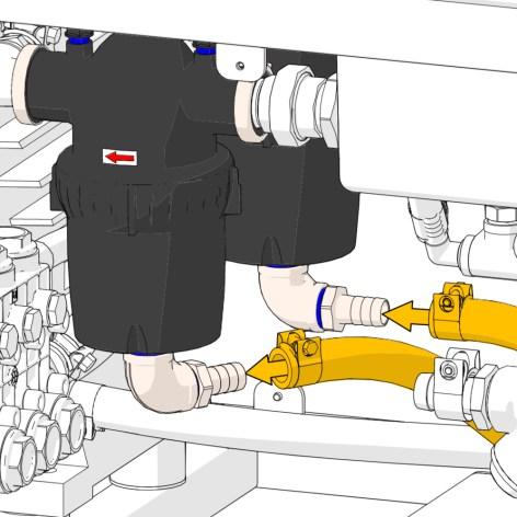
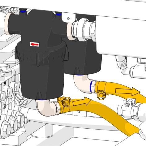
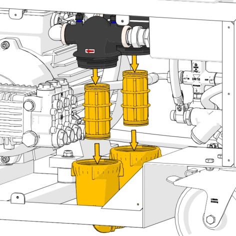
Dismount the Y-strainer cap and filter insert.
Empty the Y-strainer for dirt and clean the filter insert. 9
Remount the Y-strainer filter insert and cap onto the body.
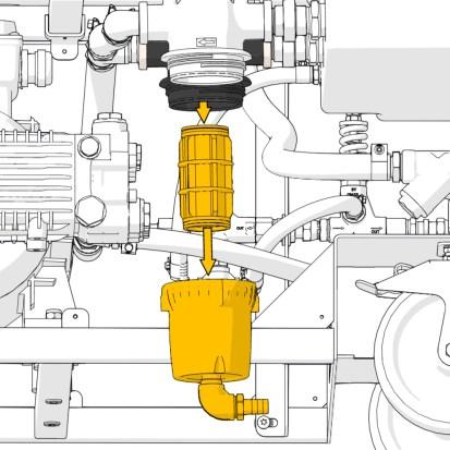
Loosen the hose clamp on the first strainer and remove the hose from the hose connector.
12 - 13
Loosen and remove the strainer with the attached fittings. 12
Remove the filter and clean it with hot water and a brush.
Do not detach or disassemble the fittings below the strainer body.
Loosen the hose clamp and remove the drain hose from the second strainer.
Loosen and remove the strainer with the attached fittings.
Remove the filter and clean it with hot water and a brush.
Do not detach or disassemble the fittings below the strainer body.
Reassemble both filter and strainer bodies.
Do not use tools for tightening.
Reattach both drain hoses to the bottom of the strainers and tighten the hose clamps.
Mount the right side panel.
Press and hold the start and stop button simultaneously for 10 seconds to reset the service alarm.
Connect the 400 V power. 20 Turn ON the main switch. 22
Reset the emergency stop.
This concludes the 50/500 hours service.
During the first start-up after service, be aware of the following:
• Leaks on the low-pressure system.
• Abnormal noises from the pump.
- 1000 hours
1 - 2
Open the tank lid and wash down any dirt and debris on inside of the tank.
2 1
Take care not to damage the float valve.
Do not use high-pressure.
Dismount both side panels.
4.Remount the drain plug (40 Nm). 5 4 - 6 Remove the oil dipstick 4 By hand remount the oil dip stick 6
1.Place a container under the pump to collect the oil.
2.remove the drain plug.
3.wait for the oil to drain.
Be careful not to damage the seal. 7
Dismount the Y-strainer cap and filter insert.
8
Empty the Y-strainer for dirt and clean the filter insert.
Remount the Y-strainer filter insert and cap onto the body. 9
Loosen both hose clamps and detach the two drain hoses from the strainers.
12
Clean both filters with a soft brush and hot water.
11 - 12
Remove both strainer bodies and filters.
Do not detach or disassemble the fittings attached to the strainer bodies.
11
13 - 14
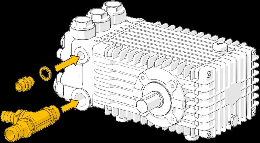
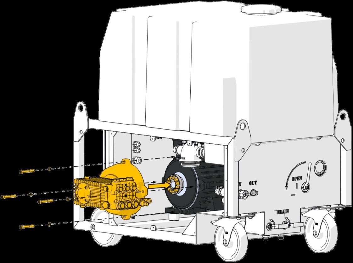
Loosen the collar and detach the high-pressure hose from the pump.
Loosen the two hose clamps and detach the hoses.
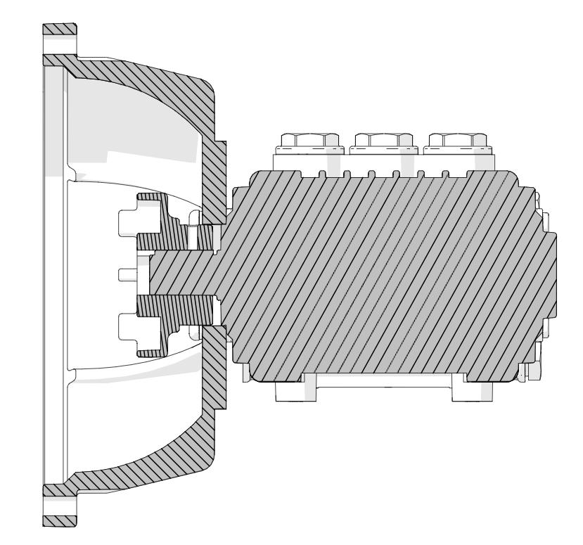
Dismount the four bolts and lock washers.
Detach the motor flange and pump.
Watch for the loose nuts on the two sides and the bottom.
-
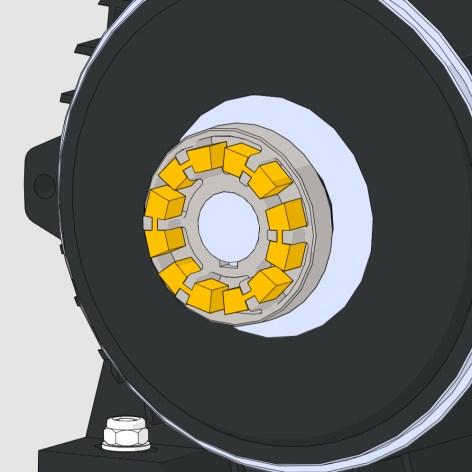
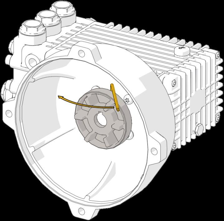
Change the rubber coupling elements with new ones. x6
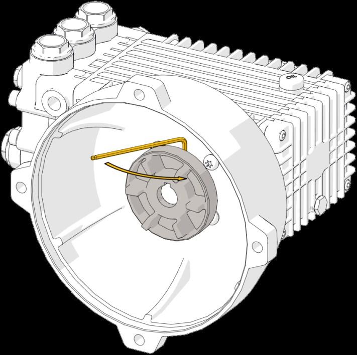
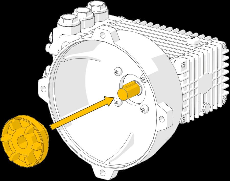
On the back of the pump coupling, loosen the set screw with a 4 mm Allen key.
Remove the pump coupling.
- 1000 hours
Dismount the four bolts and lock washers.
Detach the motor flange from the pump.
- 21
Remove the fittings from the pump.
Two options are available at this step in the service procedure.
1. Performing the pump service.
2. Ordering a new or a serviced pump from CLIIN Robotics.
1. Pump service
The following are required for a pump service:
• Replacement of seals and valves.
• Replacement of piston guide oil seals (only if the pump looses oil).
• Special extraction and insertion tools are required not to damage seals and sealing surfaces.
Consult the maintenance chart and contact CLIIN for ordering service kits and special tools.
Instruction videos and further information can be found on www.interpump.it.
• HPS0004 pump type no. SSU2050
• HPS0005 pump type no. W2141
2. Pump replacement
Contact CLIIN for ordering a new or serviced pump.
Make sure the pump oil is drained completely before shipment as the oil dip stick is not leak free.
Continue to next service step.
24 - 25
Mount the high-pressure fitting and bonded seal onto the pump.
Apply anti seize paste on both threads.
Mount the fittings onto the pump.
Clean the thread going into the pump and apply sealing compound.
The T-way must point slightly downwards from horizontal to enable a proper drainage route.
New or serviced pump.
- 1000 hours
Mount the four bolts and lock washers.
Mount the motor flange onto the pump.
Apply grease to the pump shaft to ease assembly/disassembly.
Mount the pump coupling.
Service - 1000 hours
On the back of the pump coupling, tighten the set screw with a 4 mm Allen key.
Post assembly distance.
Coupling → pump shaft.
5 mm
Mount the four bolts and lock washers. 33
Make sure all six coupling elements are in place. Align couplings for easier assembly.
Mount the motor flange and pump.
On the sides and bottom, the screws are to be fastened with nuts.
Mount the high-pressure hose onto the pump and tighten the collar.
Mount the hoses onto the fittings on the pump and tighten the hose clamps. 35
Reassemble both filter and strainer bodies.
Do not use tools for tightening.
Reattach both drain hoses to the bottom of the strainers and tighten the hose clamps.
Loosen the two hose clamps and detach the hoses from the fittings. 38
Loosen the collar and detach the high-pressure hose.
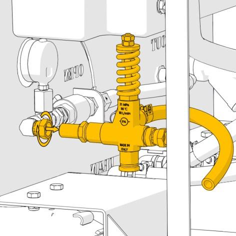
Loosen the bolt on the top of the valve bracket. Do not dismount.
Loosen the bolt on the bottom of the valve bracket. Do not dismount.
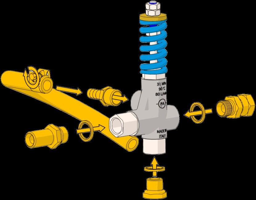
Loosen the collar and the nut to remove the safety valve assembly. 42
Dismount the safety valve assembly.
The safety valve can now be replaced by a serviced or a new one.
Consult the maintenance chart and contact CLIIN for ordering.
Remove the fittings from the safety valve. 44 - 45
• Service of the safety valve must be performed by CLIIN.
• Under no circumstances tamper with or adjust the safety valve.
• Any warranty of the system will be waived if the safety valve has been tampered with.
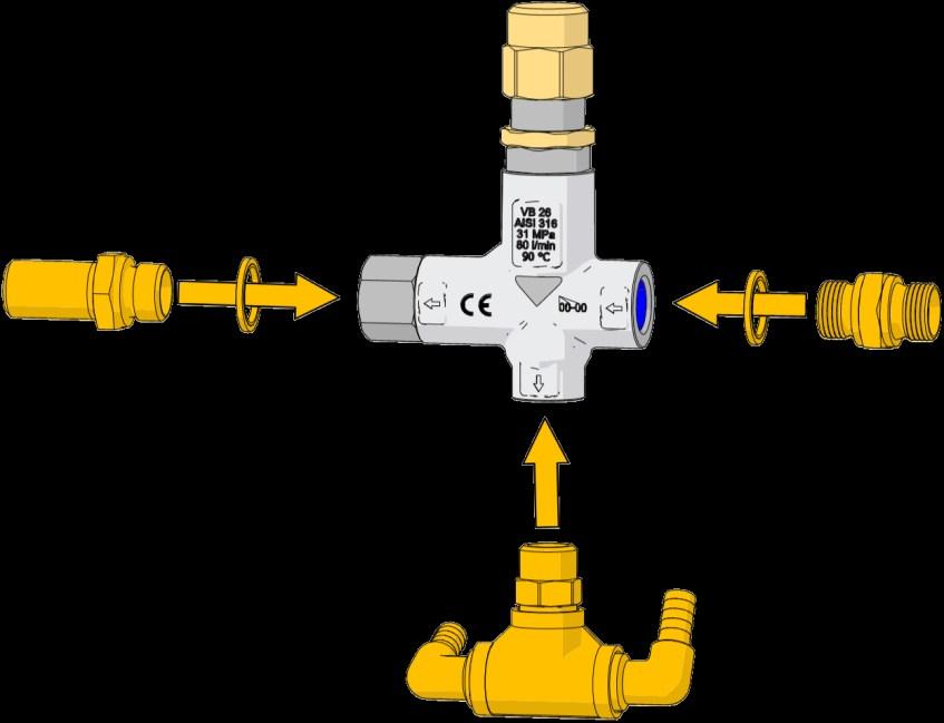
Mount the high-pressure fittings and bonded seals onto the safety valve.
Apply anti seize paste on all threads.
Bottom fitting orientation
Mount the fittings onto the safety valve bypass port.
Clean the thread and apply sealing compound.
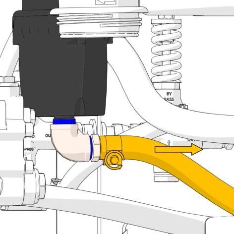
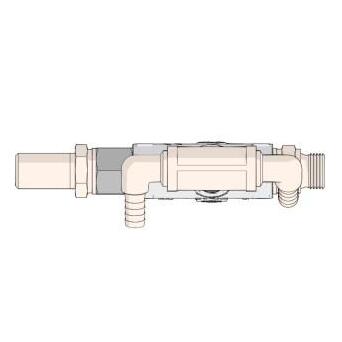
Loosen the collar and dismount the pressure regulator assembly.
Loosen the hose clamp and remove the hose.
Remove the fittings from the pressure regulator.
The pressure regulator can now be serviced or replaced. Consult the maintenance chart and contact CLIIN for ordering service kits.
52
53
Mount the hose on the hose connector and tighten the hose clamp.
Mount the hose connector onto the pressure regulator bypass port.
Clean the thread and apply sealing compound.
Mount the high-pressure fittings and bonded seals onto the pressure regulator. Apply anti seize paste on all threads.
New or serviced pressure regulator.
Mount the pressure regulator assembly onto the high-pressure elbow.
Apply anti seize paste on the thread.
Place the two washers on either side of the valve assembly bracket.
Mount the safety valve assembly.
Tighten both bolts to secure the valve bracket.
62
Mount the hoses and tighten the hose clamps.
Mount the high-pressure hose onto the safety valve assembly. Apply anti seize paste on the thread.
Fill in oil to the middle of the oil gauge window (≈ 1 litre).
The oil is slow flowing, give it a minute to settle before reading the gauge window.
oil - SAE 15W/40
Remove the oil dip stick.
Remount the oil dip stick by hand.
Pump
Service - 1000 hours
70
69 - 71 Turn ON the main switch.
Reset the emergency stop.
71
Wait 10 seconds and ensure that the “LOW WATER/SERVICE” status indicator is still illuminated (continuously).
The tank must be empty at this stage.
73
Before connecting the freshwater hose to the vessel freshwater supply, open the supply to let any debris out.
This is to protect the High-pressure System against clogging and consequently pressure loss, cavitation and internal damage.
Connect water inlet and fill the tank.
74 - 76
75
Reset the service signal by holding the start and stop button simultaneously for 10 seconds.
74
As the water level rises the “LOW WATER/SERVICE” status indicator must shift from continuous lit to flashing.
76
The “LOW WATER/SERVICE” status indicator will turn OFF. The tank must contain water at this stage.
- 1000 hours
Watch for leaks on the low-pressure system. I.e. strainer, inlet hoses, drains, fittings and sensors mounted on the tank.
Open the high-pressure valve (horizontal position).
Connect the highpressure hose to the system output connection.
- 1000 hours
80
Start the system by pressing the start button.
Wait 5 - 10 seconds then press the stop button.
82
• When water is flowing consistently continue to next step.
• If water was not running consistently wait 10 seconds before repeating service step 80 and 81 again.
No high-pressure equipment must be attached to the end of the main hose.
83 - 85
83
• Connect the high-pressure hose to the pistol.
• Lock the high-pressure coupling. Press the black collar towards the hose and turn it either way to secure it.
Main hose
Connect the doublebarreled lance to the pistol.
84
85
Turn the handle clockwise to utilise the small nozzle. This is important when adjusting the pressure.
Keep the gun activated.
Start the system.
Remove the top nut.
Monitor the pressure on the pressure gauge.
Do NOT adjust the pressure higher than stated. This can cause damage to the Highpressure System and electrical installations.
Adjust the pressure to max 195 bar by turning the nut on the pressure regulator valve.
• Clockwise to increase pressure.
• Anticlockwise to decrease pressure.
Keep the gun activated to release all pressure.
- 1000 hours
Mount both side panels.
This concludes the 1000 hour service.
During the first start-up after service, be aware of the following:
• Leaks on the system.
• Abnormal noises from the pump.
• The system stops automatically when the water level in the tank gets low.