Symbol explanation
x x x
Read and understand the manual
Wear safety glasses
Wear safety gloves
Wear safety boots
Wear hardhat
Keep clear of pacemaker
Instruction steps
Warning - Risk of electrical shock
Warning - Risk of falling objects
Careful - strong magnets
Caution - Read the explanatory text
Careful - Risk of falling objects
Careful - Risk of pinching hand
Number of personnel required
Action can prevent damage
NOTE:
This is a technical manual for integrating the robot with customer specific tools
The intention is to provide guidelines for integration and an overview over the possible plugs and outlets for external use.
Following this manual is not a requirement for purchase our use. Here refers to MANU013-RAW0011 use and maintenance.
0,8 mm
Clear rubber
High friction, low profile rubber pad.
Designed for low temperatures and highest possible friction.
Green rubber
Low friction, low profile rubber pad.
Designed for high durability for e.g. cement cleaning and cargo hold operations.
Designed to obtain the maximum friction on the magnetic tracks. Rubber is the only touching points of the robot, though local touching of single spots on the magnet may occur, if welding seams are very uneven or if the surface has rivets or similar.
2,8 mm
High friction, High profile rubber pad. Designed highest possible friction while preventing touching coating system at all times.
Low friction, High profile rubber pad. Designed to the lowest possible friction. Suitable for raw steel or rusty surfaces.
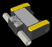
Designed to avoid touching sensitive cosmetic coatings on very uneven surfaces. E.g. white coating systems on windmills or storage tanks with uneven welding seams or smaller rivets.
Red rubber
Yellow rubber
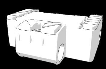
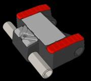
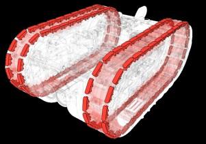
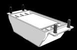
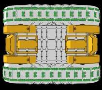
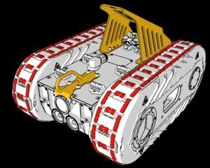
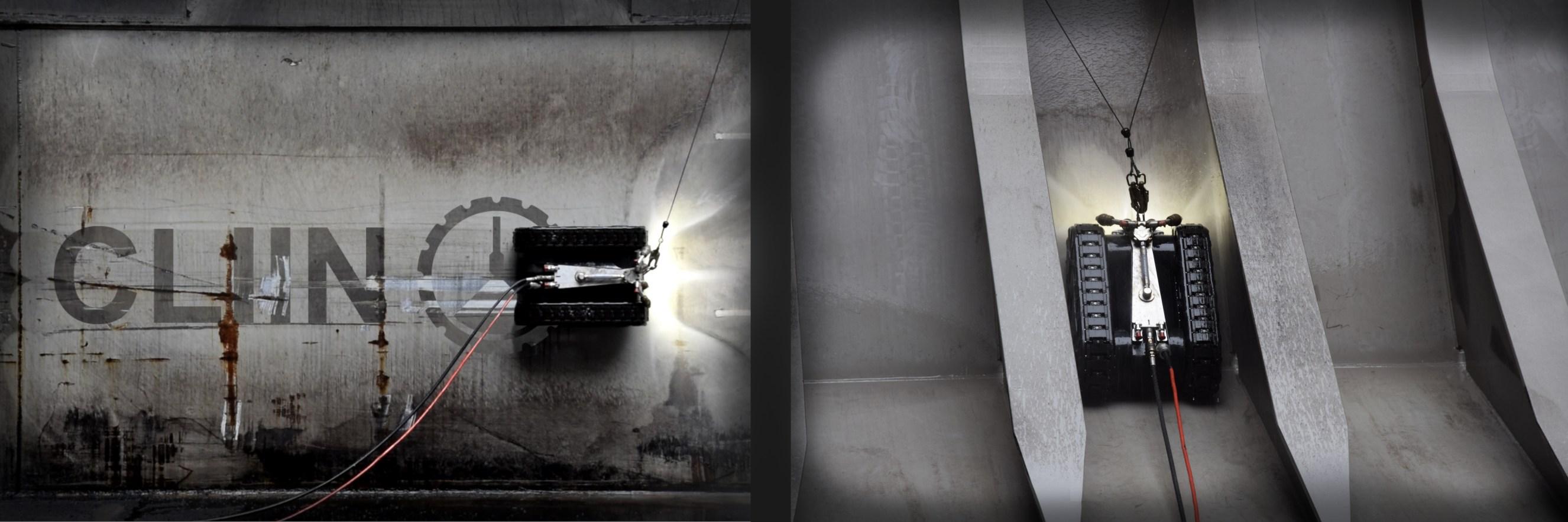
TRANSITION SETUP (FRONT AND REAR)
Tested to carry up to 150 kg in plate transitions such as upper hopper area on bulkers. Recommended max 50 kg payload. Exceeding this will compromise the safety factor.
This setup does not add more than 60 kg direct magnetic force on a flat surface.
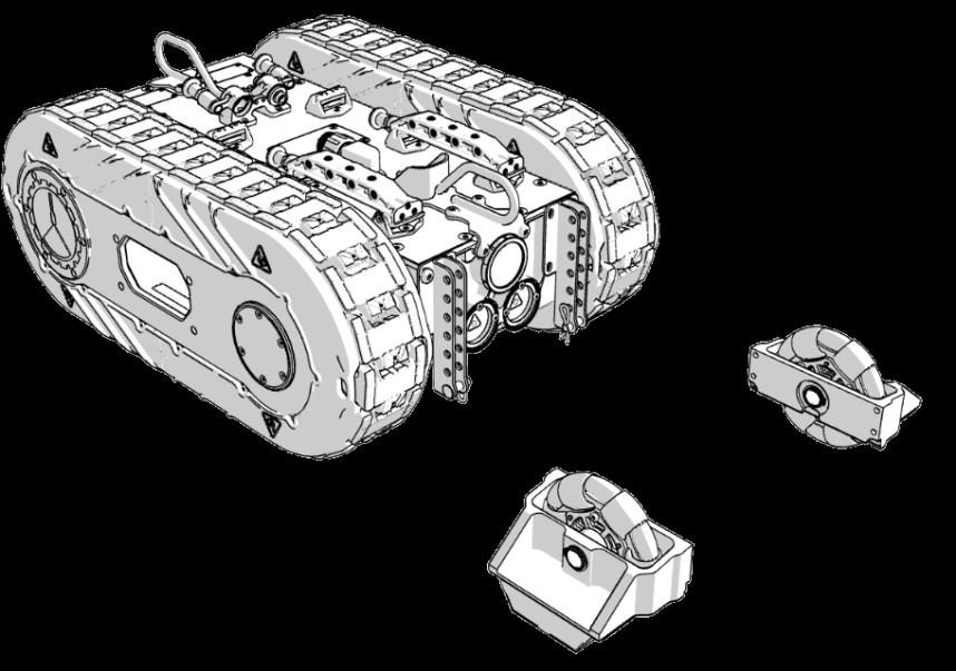
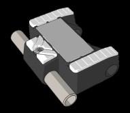
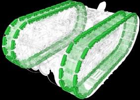
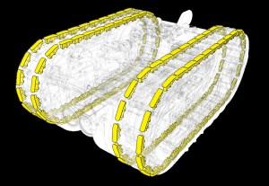
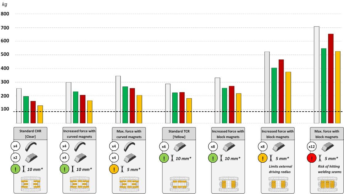
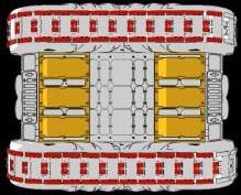
VERTICAL LIFTING ABILITIES
VERTICAL LIFTING (UP TO 12 PCS ON BOTTOM)
Each block magnet alone add 50 kg direct magnetic force on a flat surface. These are more robust and provides the optimal setup for a flat / curved surface like a vessel hull or a land based storage tanks with curvatures > 6m radius.
* All reference data on next page is performed in optimal conditions:
Magnet adhesion and rubber friction is tested on dry 20 mm steel surface @ 20° Celsius ambient temperature. Adhesion will decrease with the distance to the steel . Changes in friction will occur between chosen rubber and surface, depending on coating type and if the surface is wet or dry.
V
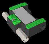
RUBBER TYPE
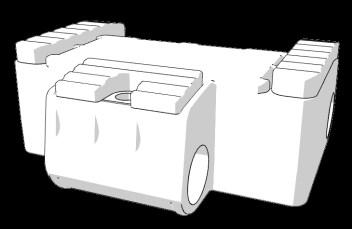
Robot base weight without tools
- RECOMMENDED SELECTION FOR CARGO HOLDS WITH UPPER HOPPER
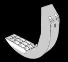
4 CURVED MAGNETS IS MANDATORY FOR THIS SETUP.
4 BLOCK MAGNETS, 2 ANGLED, 2 BOTTOM. MAY BE INCREASED TO 6 BLOCK MAGNETS IN TOTAL.
GREEN RUBBER PROVIDES THE BEST DURABILITY, THOUGH CLEAR RUBBER IS THE BETTER CHOICE FOR COLD TEMPERATURES (BELOW 8 °C)
- RECOMMENDED SELECTION FOR SLIGHTLY CURVED SURFACES
6 BLOCK MAGNETS, 3 FRONT, 3 REAR.
MAY BE INCREASED TO 8 BLOCK MAGNETS IN TOTAL DEPENDING ON
THE SURFACE TYPE (GLASS LINED ETC).
RED OR CLEAR RUBBER PROVIDES THE BEST FRICTION FOR MAXIMUM
VERTICAL LIFTING CAPABILITIES. RED IS THE BEST SELECTION FOR STOR-
AGE TANKS AND CLEAR RUBBER IS THE BETTER CHOICE FOR UNDER
WATER APPLICATIONS.
INTRINSICLY SAFE OPTION
Intrinsically safe acc. to: IEC 60079-0 & 60079-11
II 3G Ex ic mc IIB T4 Tamb < 65°C Gc
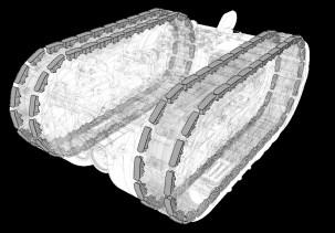
UNDERWATER OPTION
Depth sensor and navigation electronics integrated Specially sealed and approved for operations down to 60 m (6 bar)
Both of the above can be combined
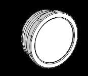
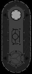
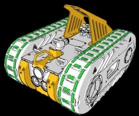
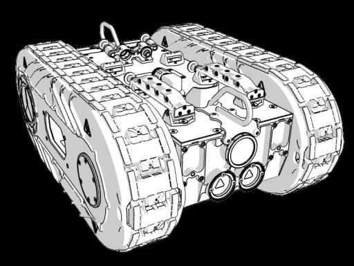
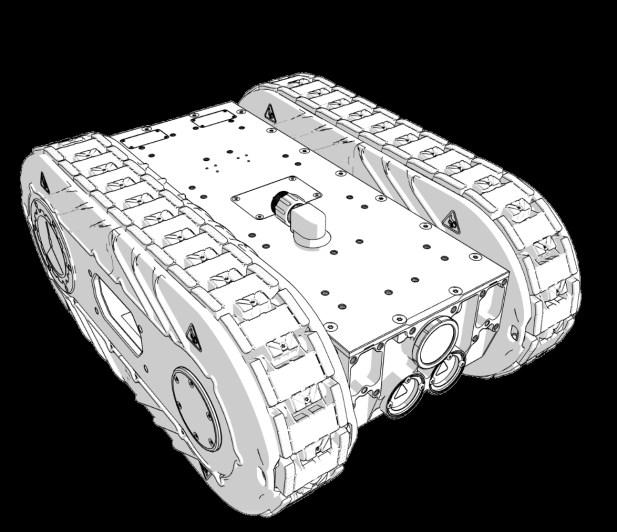
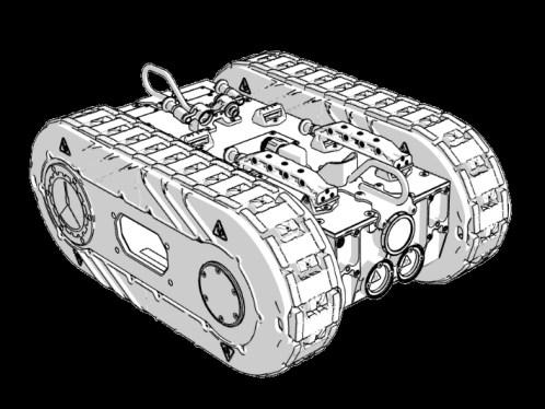
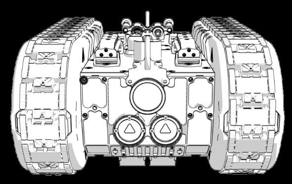
2 lights are included, one front and one rear.
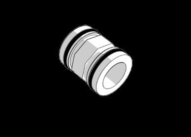
4 blind plugs with M5 thread interface, two front and two rear are standard.
All 6 plugs can be exchanged and replaced with the options on the next pages, to customize the robot to specific requests.
In each side, there is an optional mounting area. This has the primary function of mechanically integrating tool on the side of the robot to get a better stability. This will be described later.
x6
There is a total of 2 LED channels, where each channel can support up to two single LED modules or 24W.
Examples:
Channel 1: 2 internal LED modules
Channel 2: 1 external LED module -OR-
Channel 1: 1 external LED module
Channel 2: 1 external LED module
Intrinsically safe acc. to: IEC 60079-0 & 60079-11
II 3G Ex ic mc IIB T4 Tamb < 65°C Gc
It is possible to mount up to 4 Internal lights, if no other lights are mounted. Specifications are:
4000 K
9W LED x4
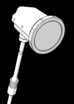
External lights is another option. Up to two external lights can be added. These are designed to be very powerful. Specifications are:
6000 K
23W LED
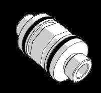
The external LED is powered through a micro circular SubConn connector with 2 pin (+1 poke yoke pin) .
Cable length is 600 mm, with a possible extension up to 5000 mm
Step-file for mounting of external lights available on request. x2
Intrinsically safe acc. to: IEC 60079-0 & 60079-11
II 3G Ex ic mc IIB T4 Tamb < 65°C Gc
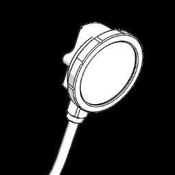
Up to two external outlets for Ethernet are available through a 8pin micro circular SubConn connector.
This allows for passing a two twisted pair Ethernet connection (10/100 Mbps) and 12V@0.5A max power to the external camera
Generally anything that needs an ethernet connection and/or a 12V@0.5A (max) power supply can be connected to these outlets.
The specifications for the external camera:
Resolution: 1080p, 2MP, 50fps
Cable length is 600 mm, with a possible extension up to 5000 mm
Step-file for integration of external cameras available on request.
Intrinsic safety depends on external tool / device.
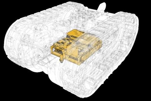
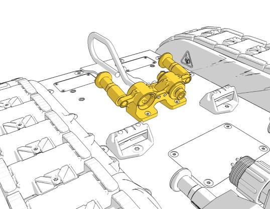
If a customs device needs power supplied from the robot, this can be done through a 5 pin SubConn Micro
Circular connector cup which allows for passing power from an embedded power supply to the outside of the robot. The pins in the plug can safely carry up to 5A. The power supply will be mounted on a bracket inside the robot. Exceeding 90W will need an assessment to determine if we have enough room inside the robot for the requested supply.
An example:
Configuration with a 90W ( 24VDC@3.75A.) power supply for driving a customer's external flood light has previously been done.
Note: There are no control pins in this cup, only the power connection.
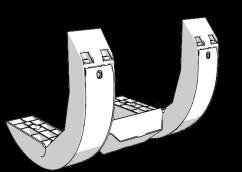
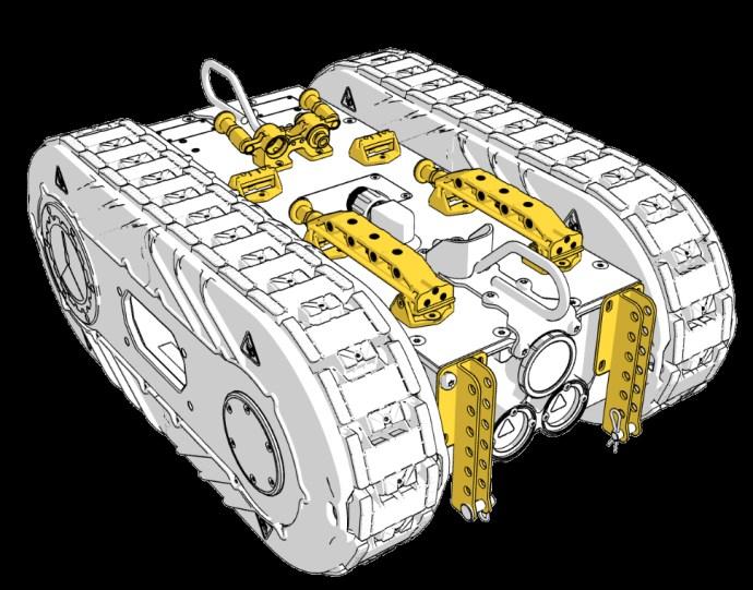
Cable Brackets
Quick release locking system for cables and hose management.
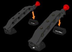
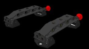
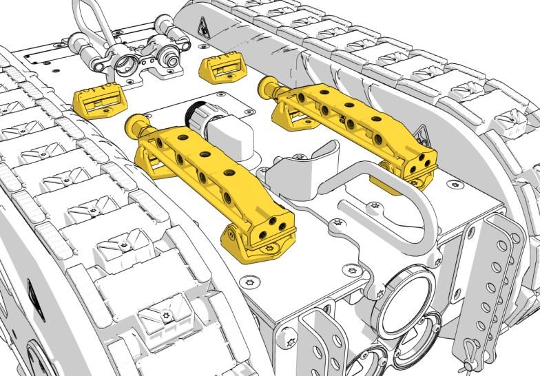
Top Brackets
Powerful polymer brackets with easy quick release locking system.
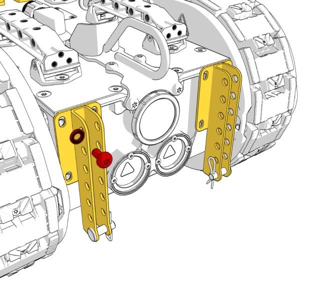
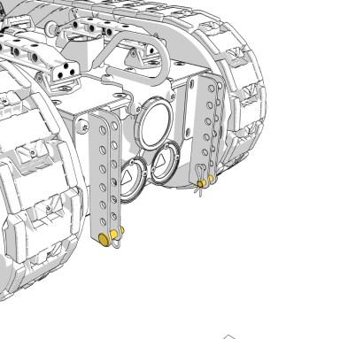
Front Brackets
Stainless front bracket with multiple mounting options and pin for pivots. Cannot be combined with transition magnet package.
Mounting
It is recommended to mount front brackets and other custom tools with a M8x16 mm pan headed screw, including an antivibration shim, e.g. Nord-lock washer.
Top brackets
M8 and M5 threaded inserts are molded into the polymer brackets to allow up to 25 kg of tools to be mounted on them. These also serve as an impact part to break in case of fall / damage.
STEP-file available on request.
Material: AISI 316L
Max 200 Bar
Antivibration rubber bands
Two versions available
M000841 / M000863
Mounting option for tools where it is needed to provide a medium like air or high pressure water / hydraulics. A fitting for the top bracket can be purchased separately and integrated. STEP-file available on request.
M5 Threads - used for cable bracket
M8 Threads - recommended for tool mounting
Front and rear available also.
STEP-file available on request
M8 mounting holes for anchors also useable, though at least one load arrest anchor must be free
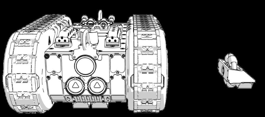
Recommended mounting
If it is not a requirement to have a fixed distance to the surface at all times, when driving over curvatures, the recommended mounting method is to make the tool hover above the surface.
It is recommended to keep the center of mass as close to the robot body as possible and thereby keep the weight of the tool as low as possible. Preferable keeping the tool mass below 30 kg will maintain full maneuverability on most surfaces.
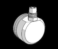
Omni directional wheels
We have good experience using omnidirectional wheels combined with magnets in a fixed distance to the surface. This allows a smooth movement. Keep wheels as close to the robot as possible. Preferable keeping the tool mass below 30 kg will maintain full maneuverability on most surfaces.
OBS!
It is NOT recommended to use a spring loaded tool. If needed contact CLIIN and we will help on this integration.
Use the MW00081 mounting brackets with pins as a pivot for the tool to flex freely and follow the surface.
OBS!
Mount in holes in robot core. Not in the side plate
Recommended mounting
If it is not a requirement to have a fixed distance to the surface at all times, when driving over curvatures, the recommended mounting method is to make the tool hover above the surface.
It is recommended to keep the center of mass as close to the robot body as possible and thereby keep the weight of the tool as low as possible. Preferable keeping the tool mass below 30 kg will maintain full maneuverability on most surfaces.
OBS!
It is NOT recommended to use a spring loaded tool. Spring loaded tools decreases robot attachment. If needed contact CLIIN and we will help on this specific integration.
Omni directional wheels
Omnidirectional wheels combined with magnets in a fixed distance to the surface provides a stable tool and robot behavior. Keep omni-wheels as close to the robot as possible. Preferable keeping the tool mass below 30 kg will maintain full maneuverability on most surfaces. Make the pivot point close to the robot.
Target implementation Q3 2025 contact CLIIN for further details
Direct control targets (preliminary)
Sensor output data to user:
- IMU
- Tilt sensor
- Depth sensor
- Wheel odometry
- Temperature data, ambient and motors
- Internal pressure data
Control data (input for robot):
- Forward / Reverse of each motor
- Light control