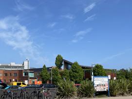
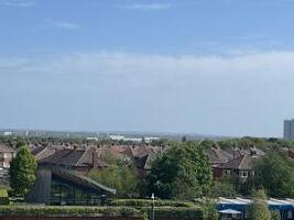
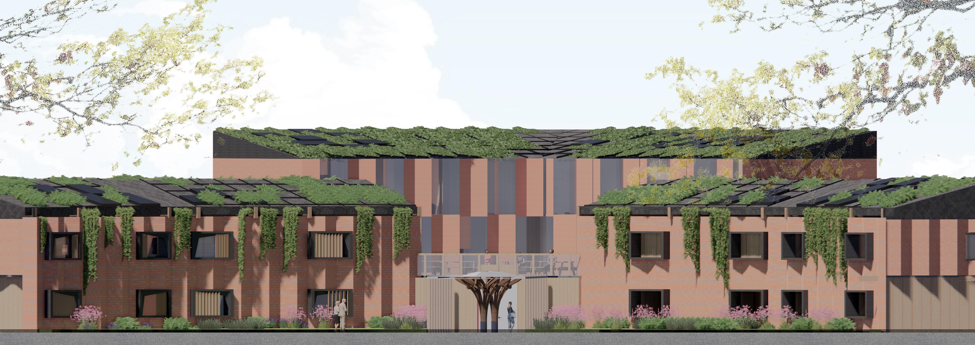
"Freeman dementia centre"; Freeman hospital Newcastle UK; NE7 7DN
Studio 4 House of memories
Tutor: Neveen Hamza and Stuart Franklin 180605899
1
Xiwen XU ARC3013 ARCHITECTURAL TECHNOLOGY 3: INTEGRATING CONSTRUCTION
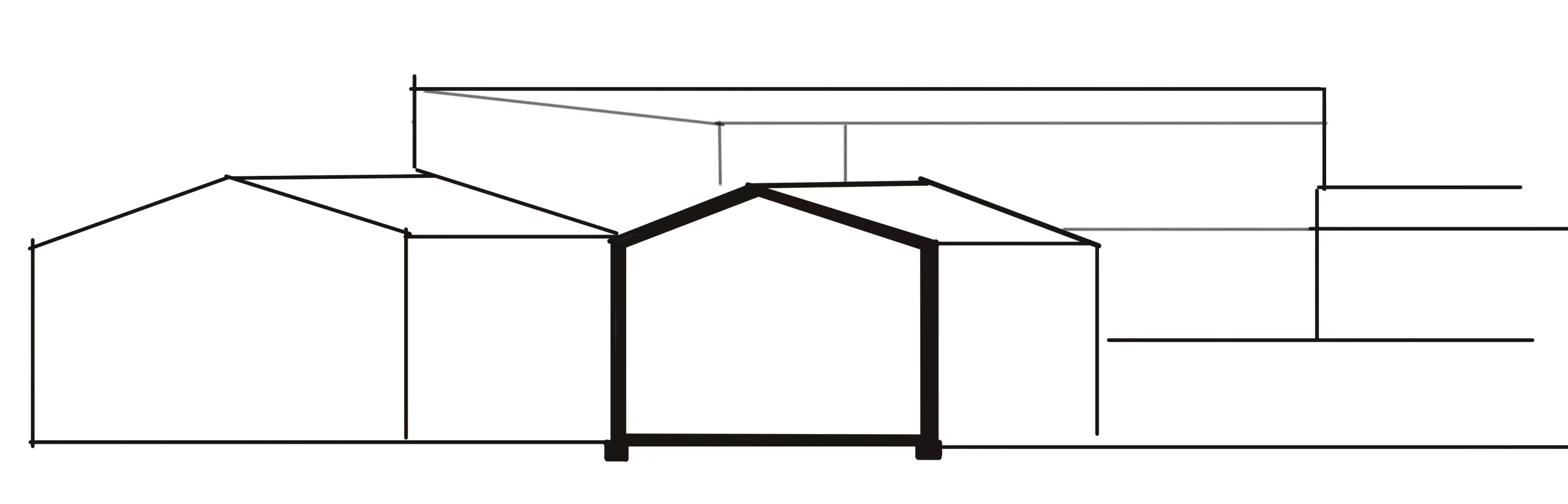
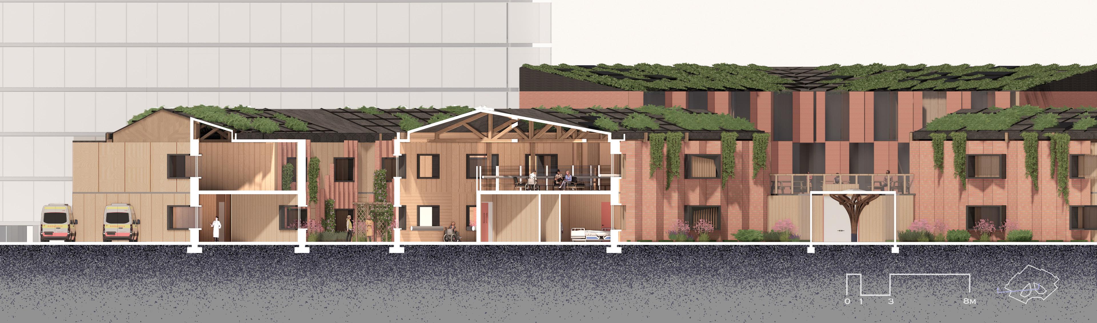
section
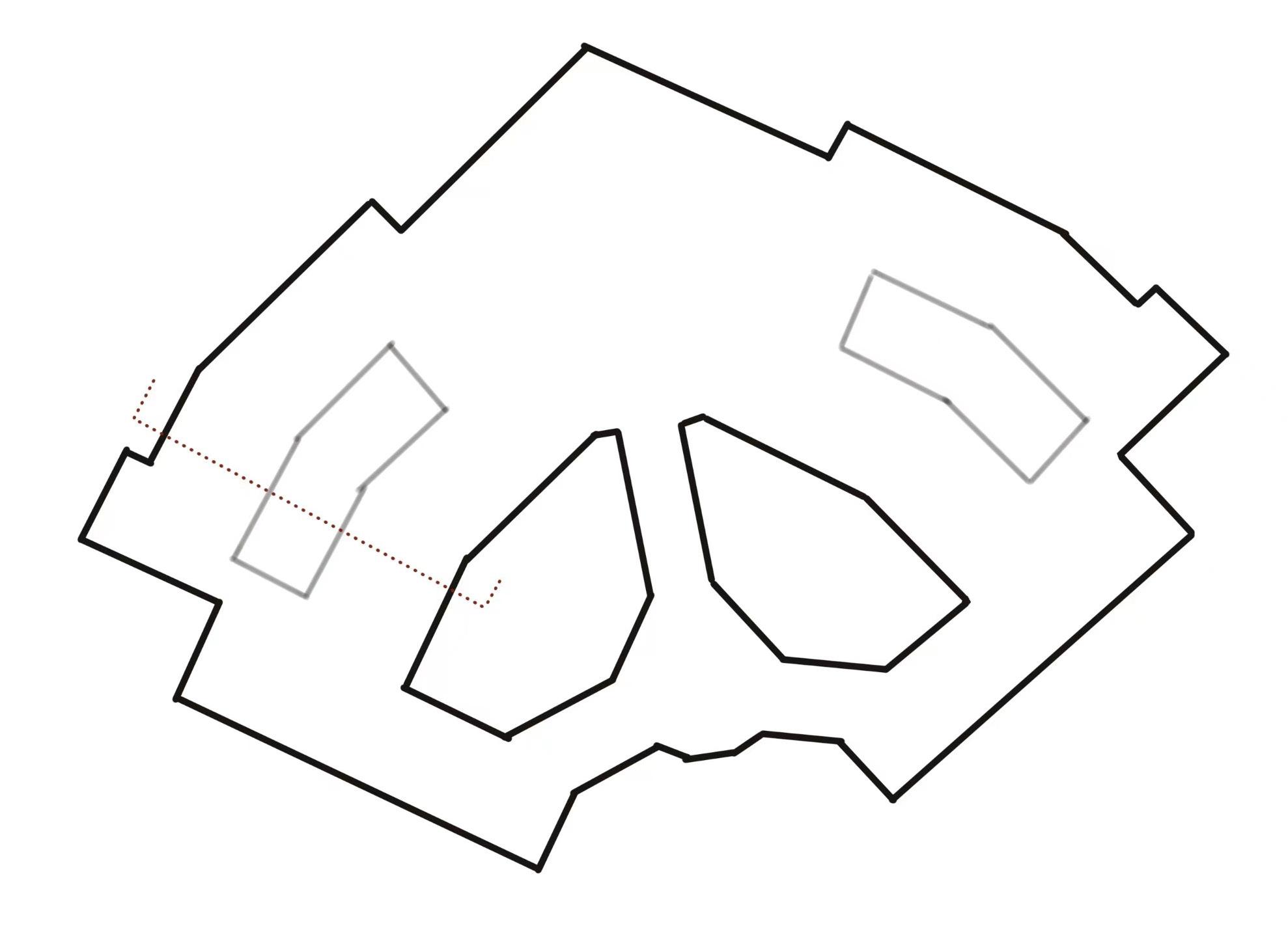
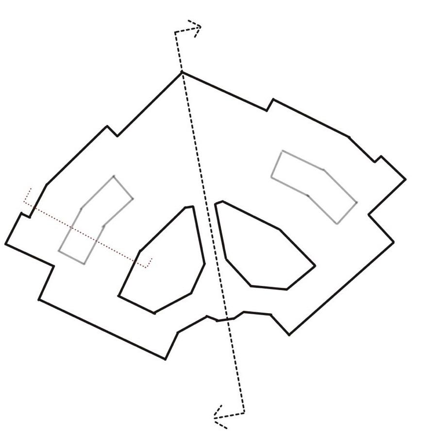
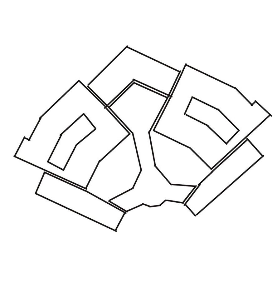
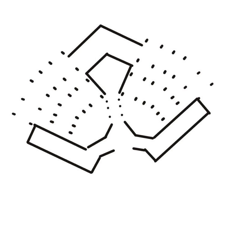
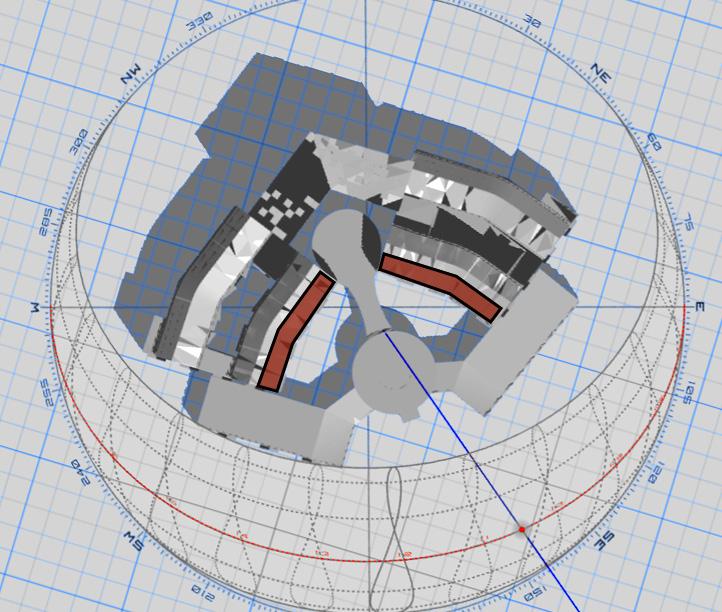
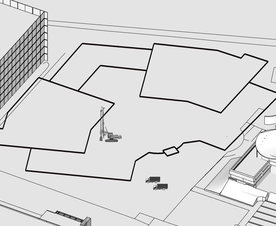
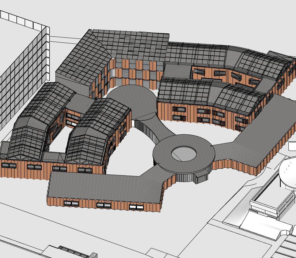
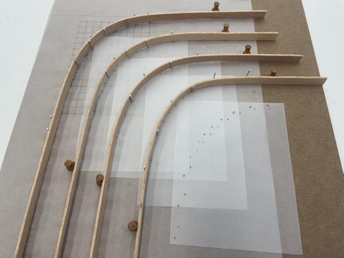
Parti Diagram
Parti Diagram plan
CONTENT
Part 01
Project Declaration pp3-5
Part 02
Technical Section and Part Elevation Study pp6-8
Part 03
Additional Technical Components pp9-19
Part 04
Studio Specific Technical Research pp20-28
Part 05
Critical Reflection pp27
Part 05
Referencing / Bibliography pp28
Part 06
List of Illustrations pp29-30
2
Part 01 Project Declaration
1.1 Written description of the project
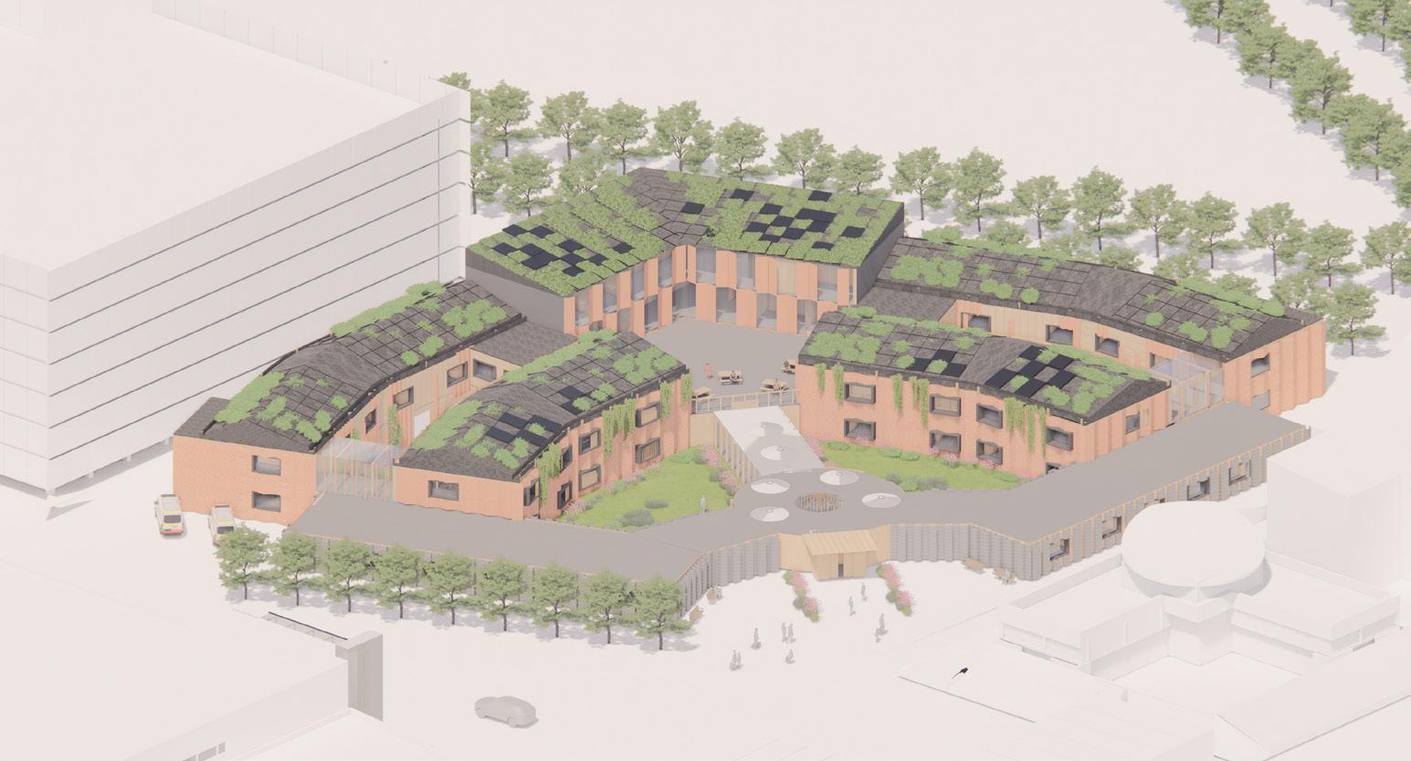
My final year study studio is called HOUSE OF MEMORIES. This studio would focus on the care home design for people who are suffering from dementia.
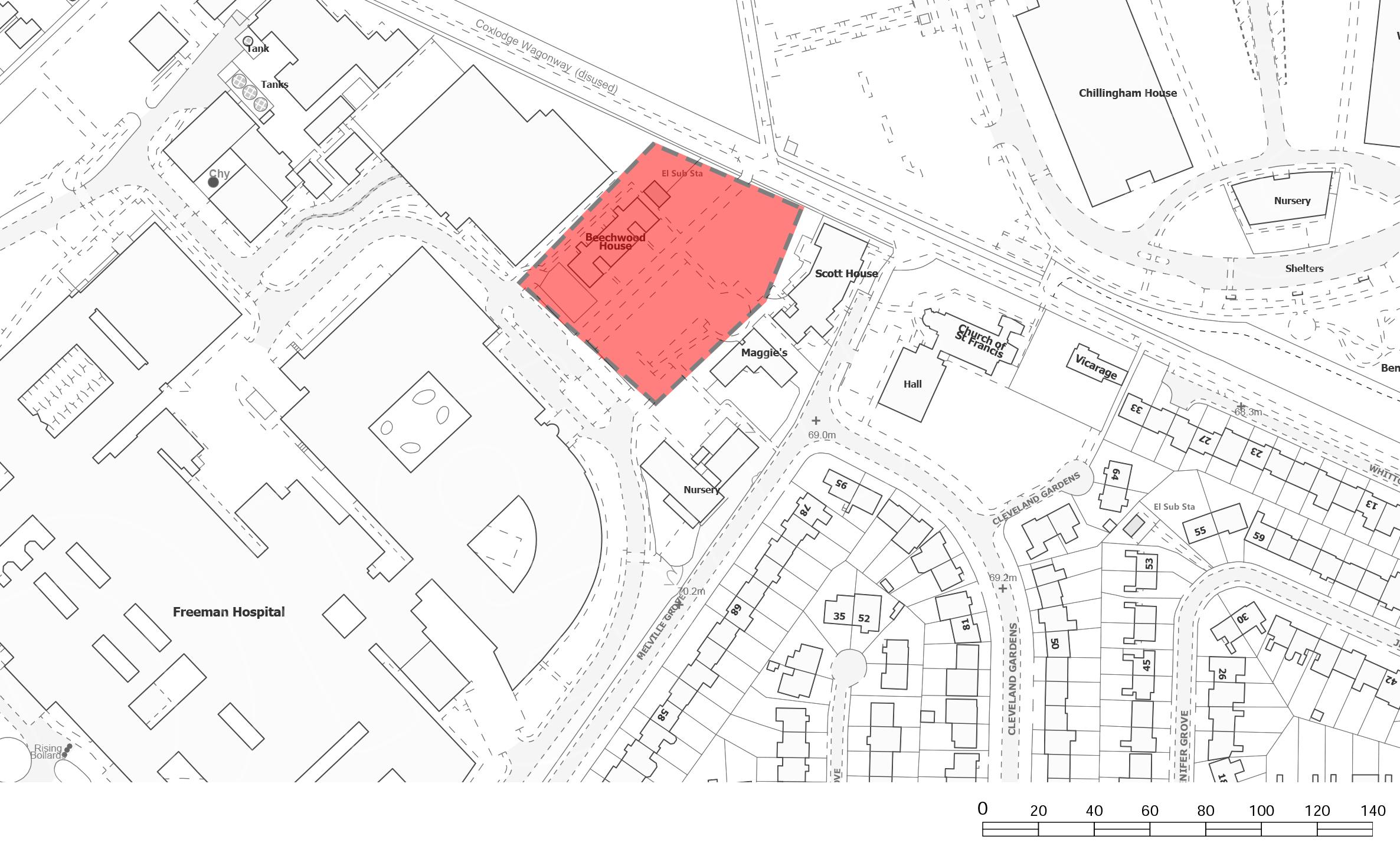
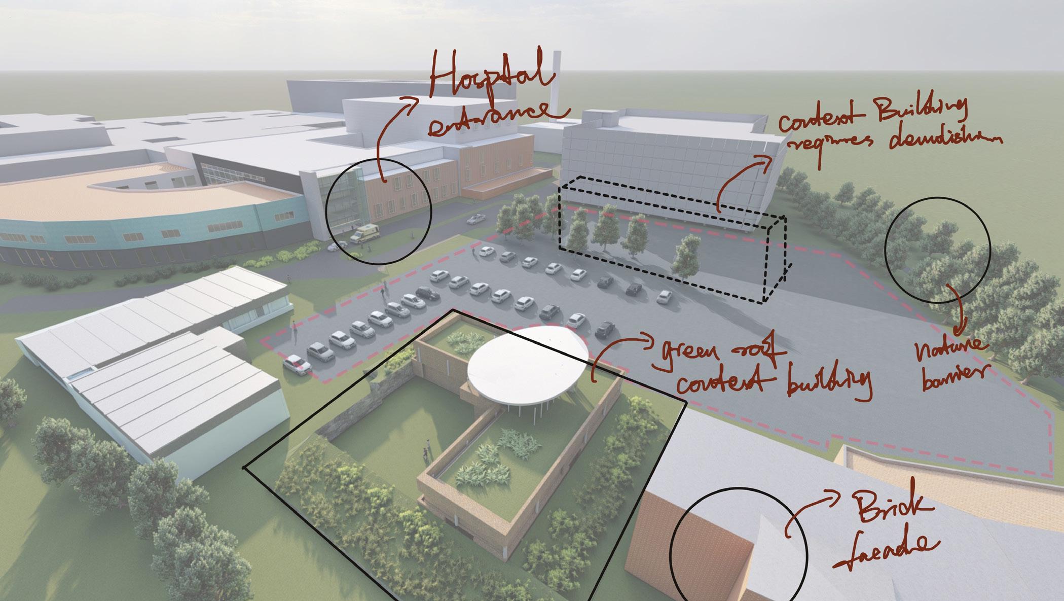
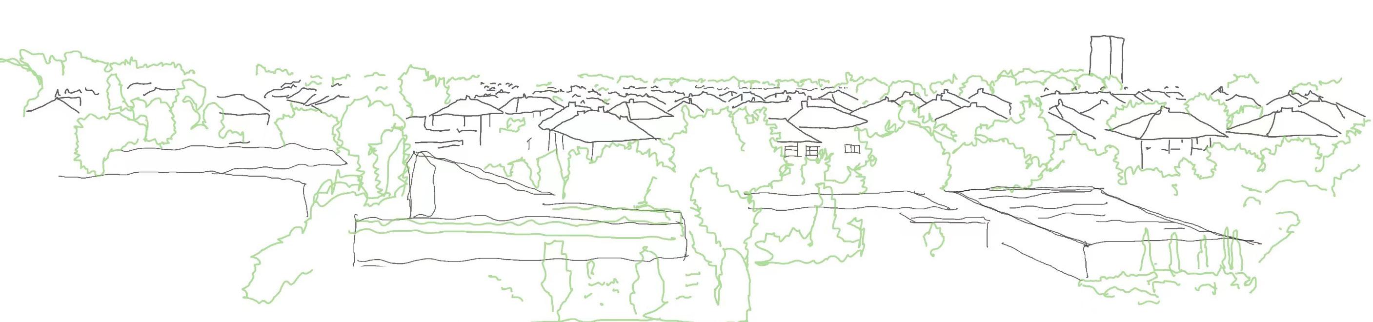
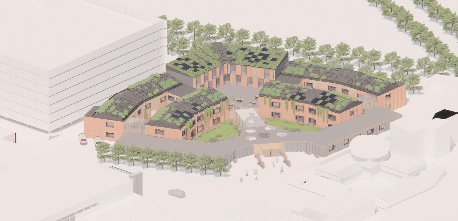
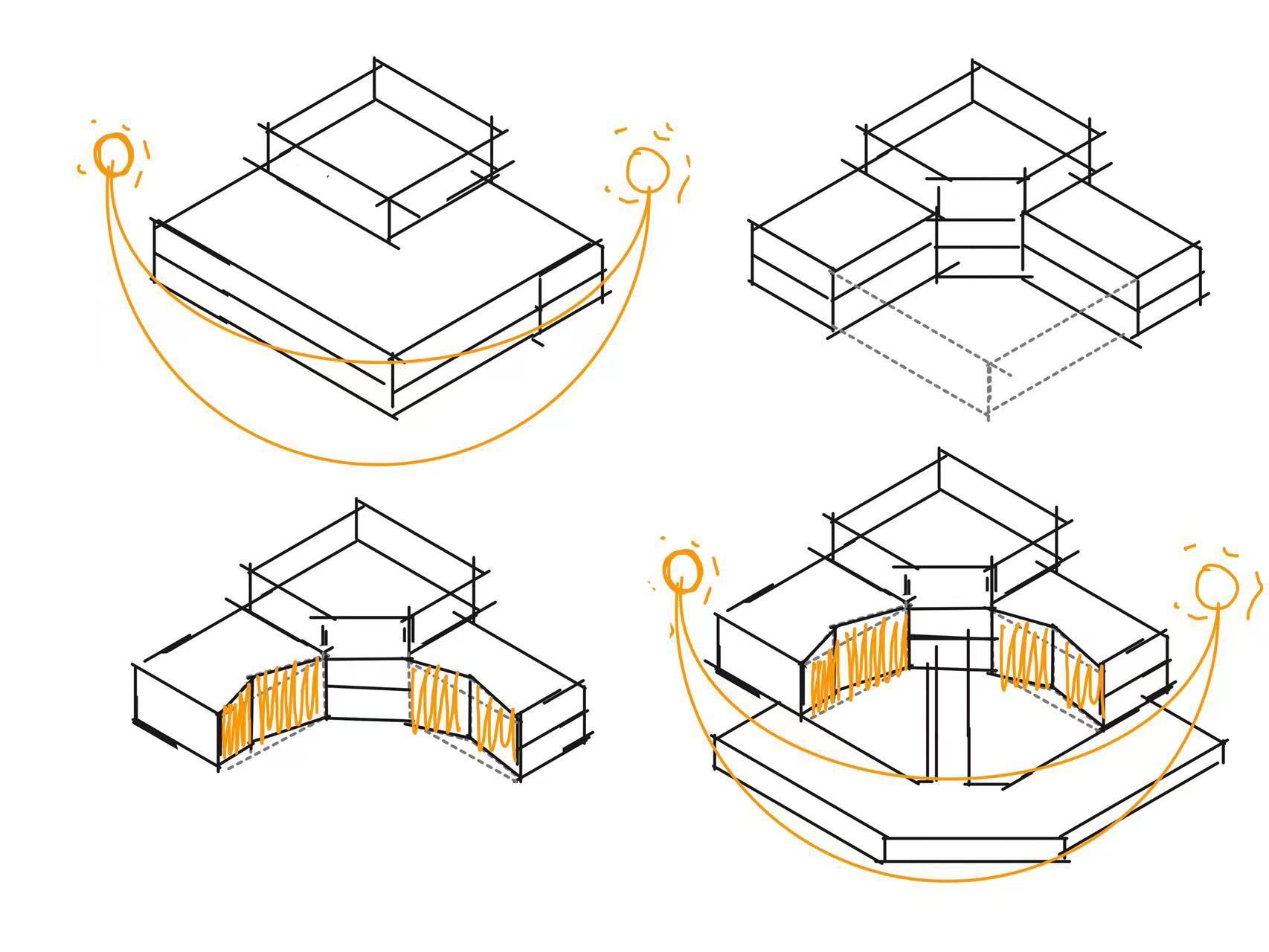
Our project site is located at the Freeman hospital in Newcastle, next to Maggie’s centre. The area of the site is nearly 1200m2, and surrounded by medical buildings mainly. This is a new build project which would involve the demolition of one existing building on the site. The main challenge of this site is the spatial arrangement; how would this large-scale therapeutic building cooperate with the existing context. To answer this challenge, I analysed the existing urban fabric as well as the building material around the site, which helped my design to fit into the context and adjust my design decision.
Regarding the design aim, my tectonic research was approached by using timber as the primary structure, as timber could provide a warm interior atmosphere, lighter and more environmentally friendly. Site
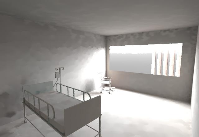
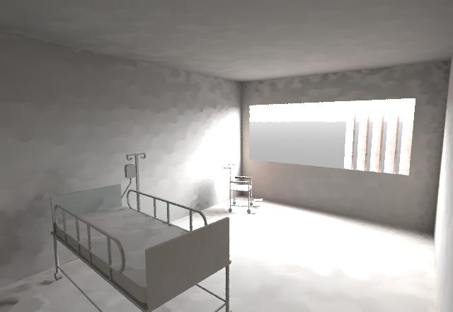
This project focuses on how to create a safe and comfortable environment for dementia patients, including how to keep the ward warm and maintain a good ventilation environment (see section 3.1). The building would need to include special fire evacuation to protect the vulnerable group (see section 3.3) and also include serious architectural form language to assist patients’ daily routine (see section 4).
3
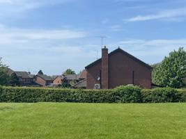
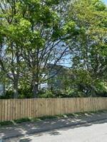
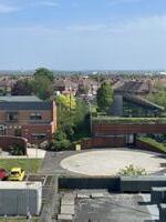
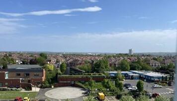
information
Site photos and urban skyline sketch 1:200 site plan
summary
1.2 Spatial Design Summary
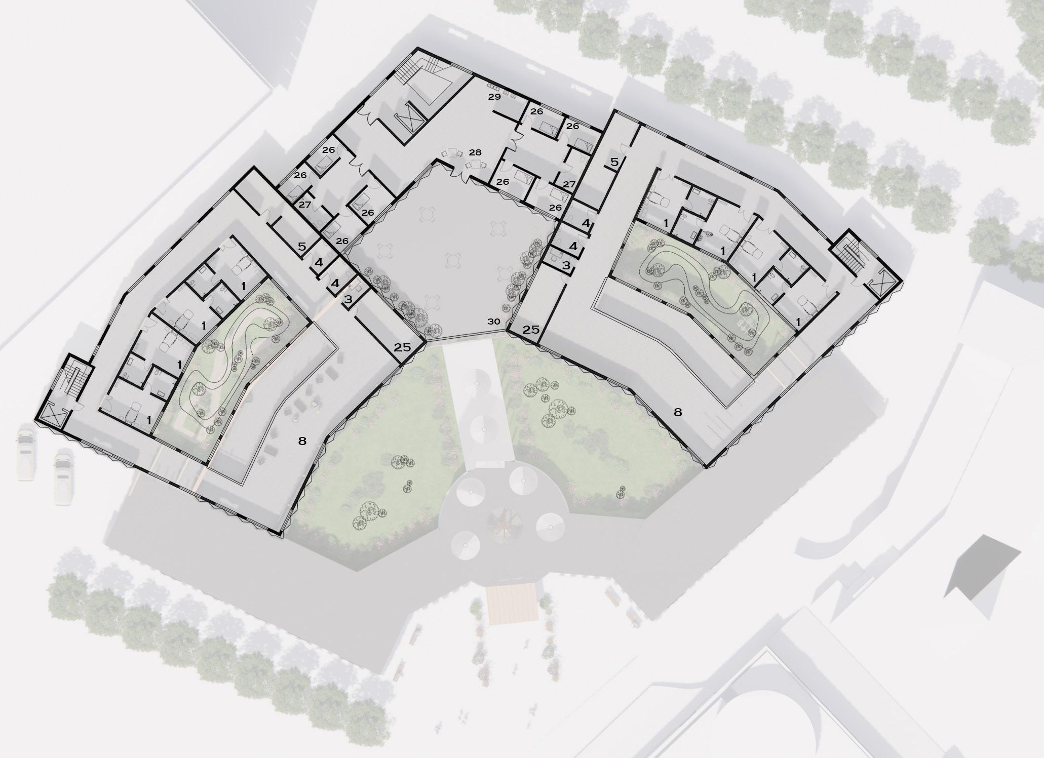
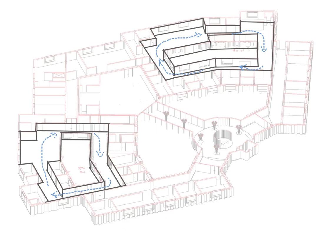
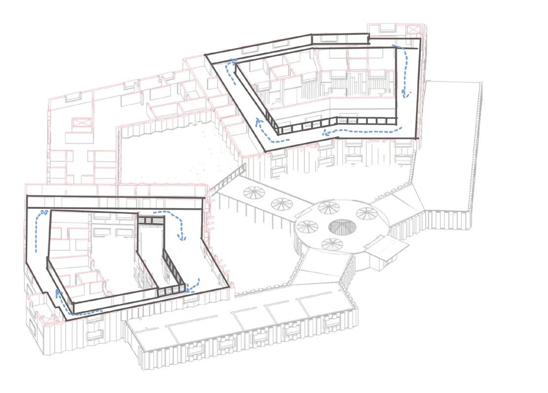
The design includes various mandatory functional spaces required in this project. In a dementia care home, the building should be separated by male and female wards, including an interior and an exterior wondering path for the patient safety. The wandering path should be a closed-loop and without any dead end to avoid agitation behavior cost by losing direction. The wards should also include an assistant bathroom and accessible toilets. The building should control the circulation and divide space into 3 types:
1. Doctors and nurses only
2. Patient and family member access
3. Patient access under supervisor
Providing the services above should meet the basic requirement of dementia care home needs. However, helping the project more caring about people. The building should also consider personalization and avoid institution-like.
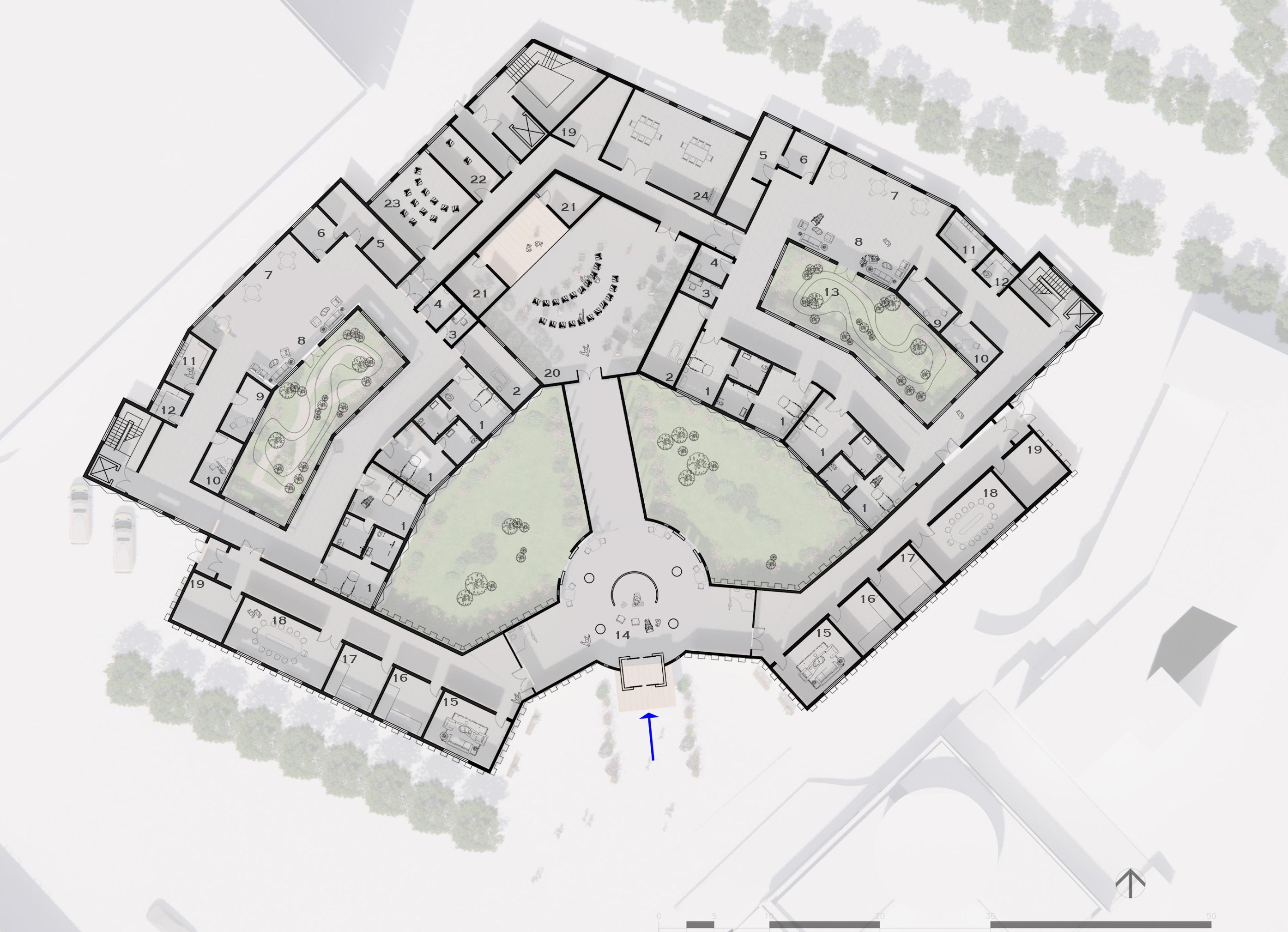
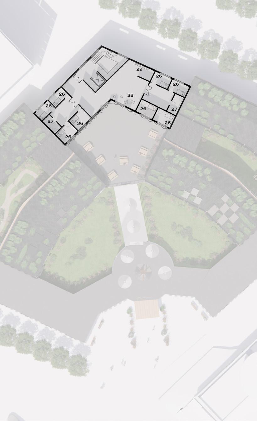
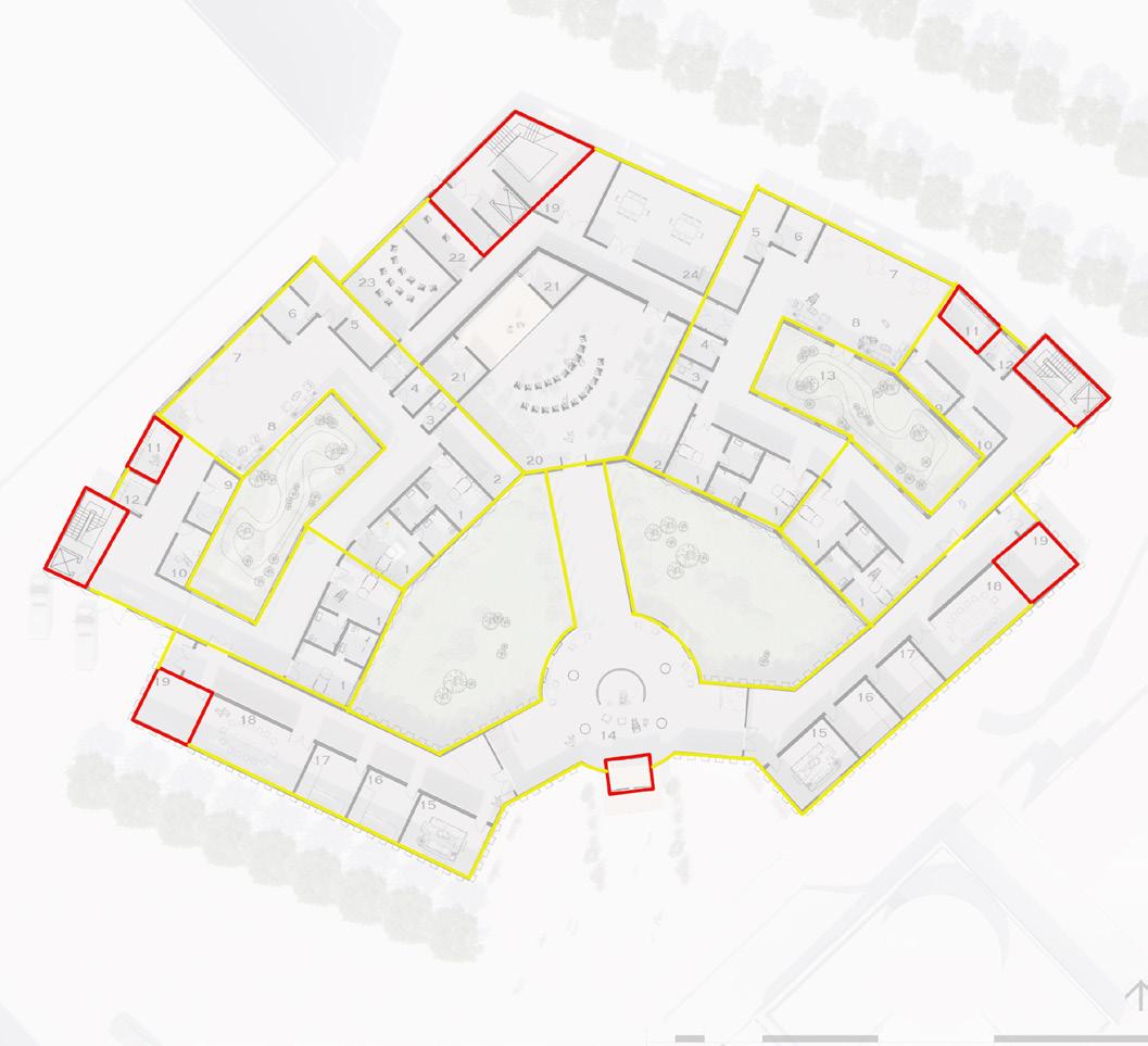
Ground floor plan
1. Pods
2. Assistance bath room
3. Ward manager office
4. Public wc
5. Nurse station & medical room
6. Assessment kitchen
7. Dining tables
8. Living room
9. Quiet room 1
10. Quiet room 2
11. Kitchen
12. Food storage
13. Private garden
14. Reception
15. Family member & patients meeting room
16. Female changing room
17. Male changing room
18. External meeting room for staff
19. Plant room
20. Intergenerational space (theatre)
21. Changing room
22. Hair salon
23. Cinema
24. Communal entertainment room
25. Laundry
26. Staff ensuit
27. WC
28. Indoor communal space
29. Kitchen
30. Outdoor communal space
4
1st floor plan 2nd floor plan
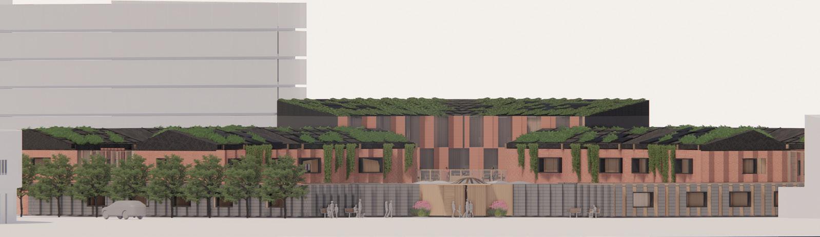
Aox view
South elevation
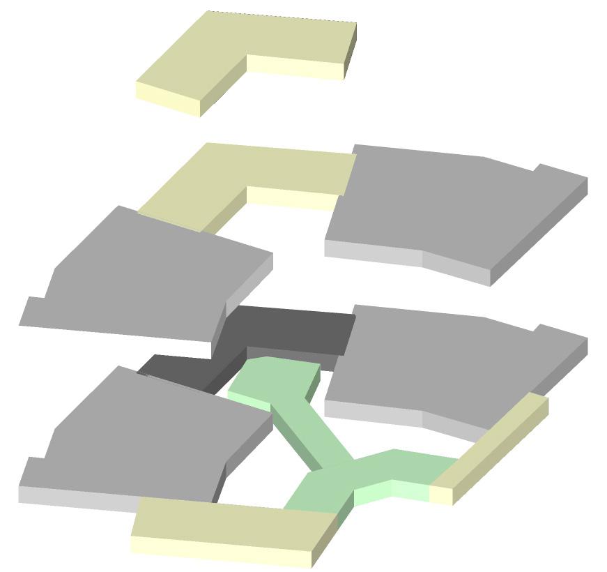
SPACE
MASSING
Unit to Whole Geometry GF wards patients friendly circulation 1F wards patients friendly circulation Structure
Part 02
Technical Section and Part Elevation Study
6
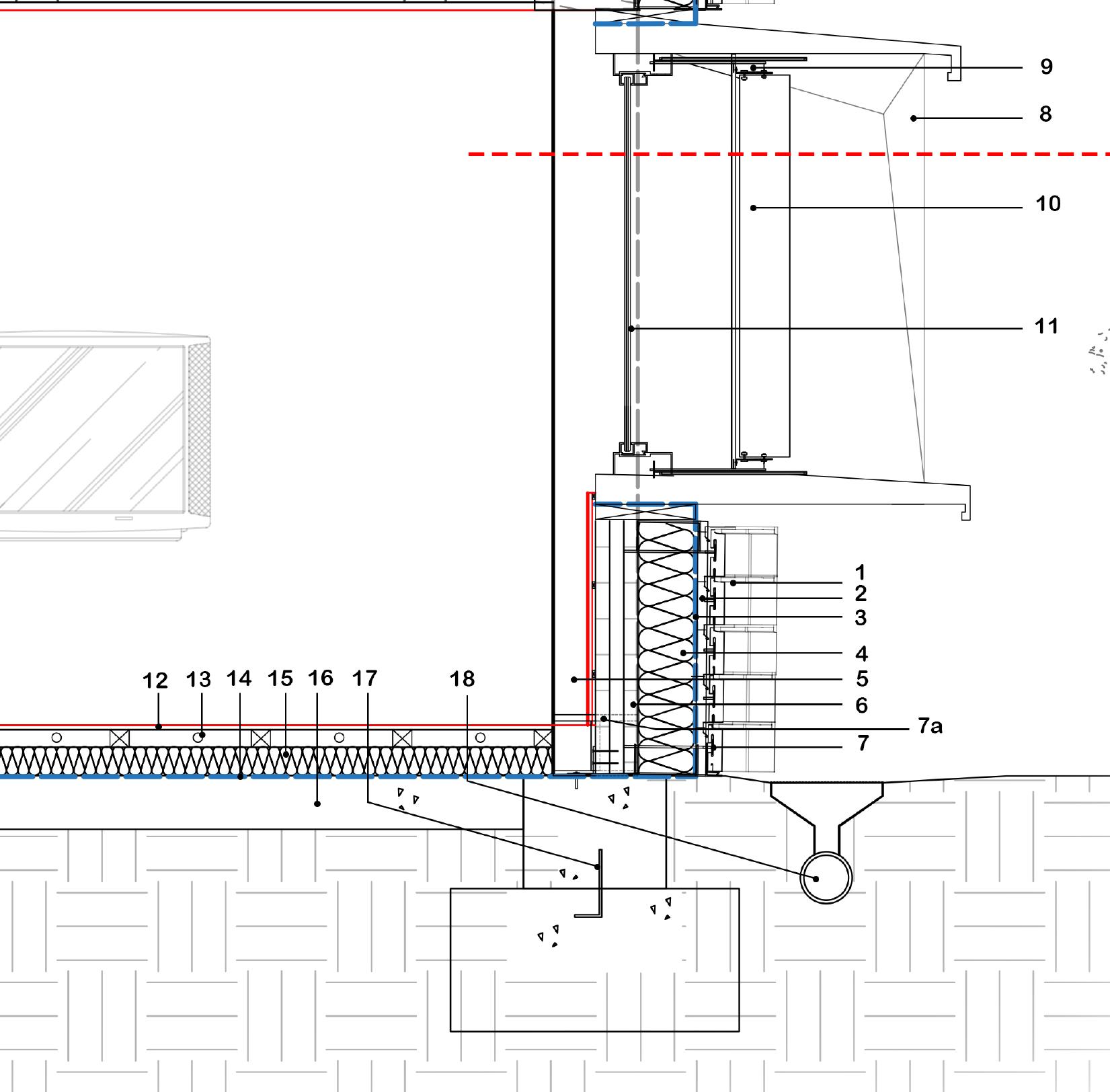
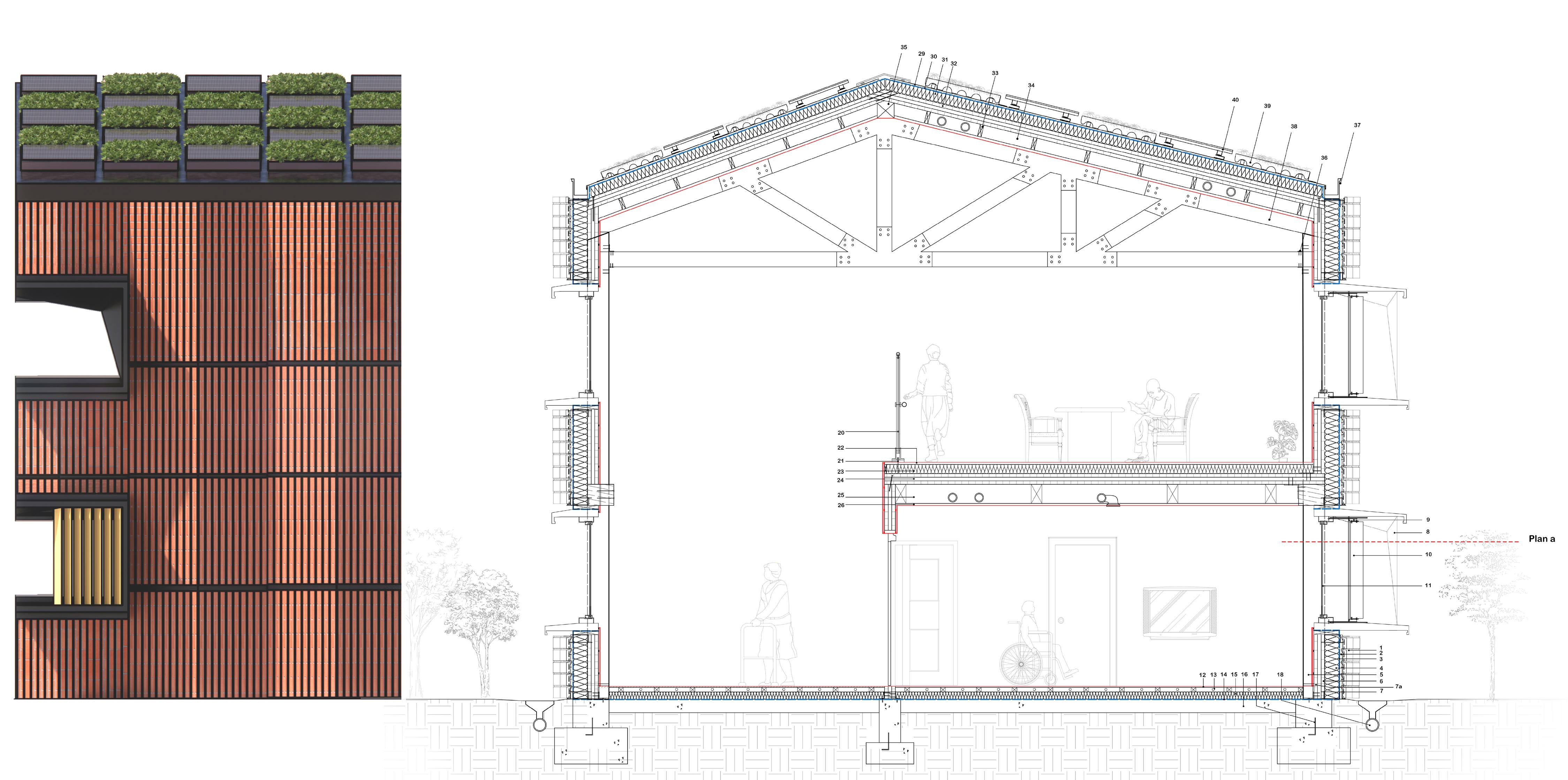
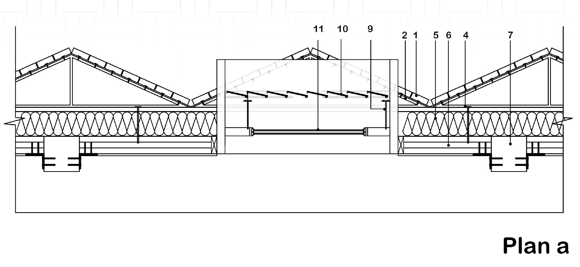
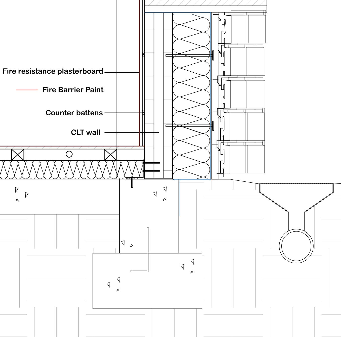
Foundation wall juction detail

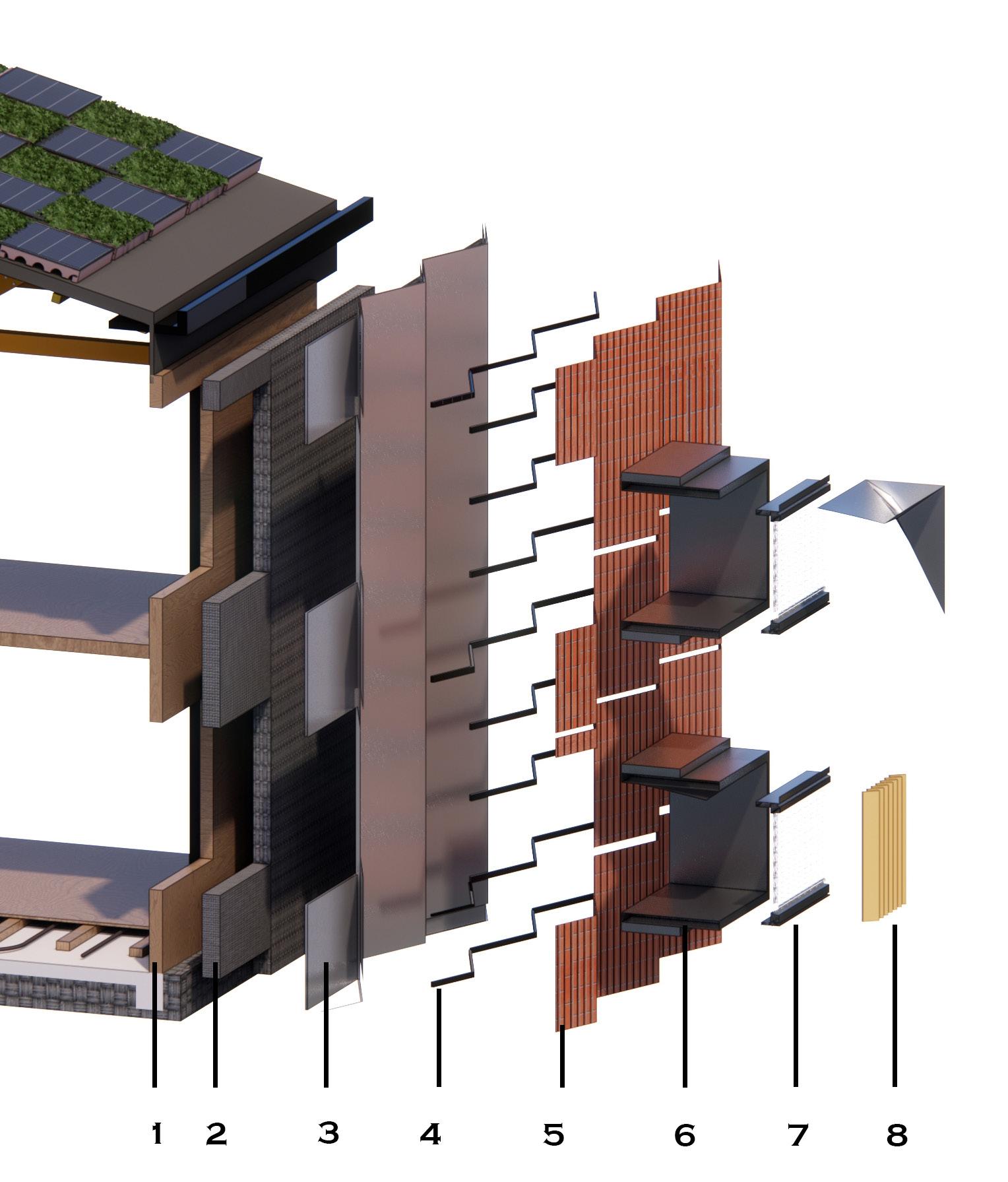
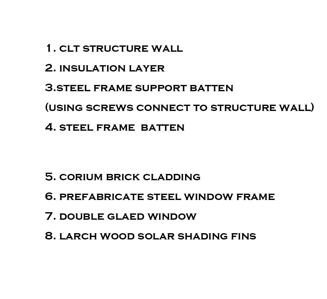
1. 20mm Corium brick cladding
2. 20mm Horizontal Battens support cladding
3. Waterproof membrane
4. Steel screws holding battens
5. 180mm Rigid foam insulation
6. 150mm CLT structure panel
7. 150 x 150mm Glulam structrue columns frame
7a. Steel footing support glulam column
8. Prefabricate steel window frame
9. Control rod of timber fins
10. Galvanized steel support timber fins
11. Double glazed window
12. 15mm Timber flooring
13. Underfloor heating
14. Waterproof membrane
15. 60mm Rigid foam insulation (load-bearing heavy insulation)
16. 200mm Concrete Floor slab
17. Concrete footing with a L proflie steel connect to floor slab
18. Drainage connect to the water collecting tank
7
Window , external wall juction plan
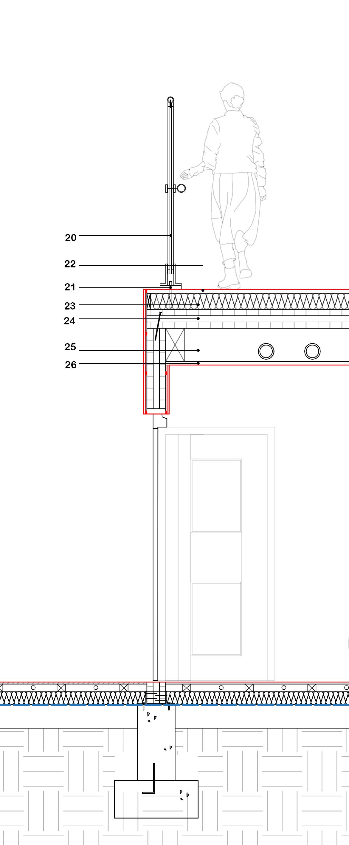
20. 1500mm Height Glass plane (in compliance with Approve Document M)
21. Bottomrail support by steel tie, fixed to the CLT floor panel
22. 12.5mm timber flooring
23. 120mm Rigid foam insulation
24. 150mm CLT floor slab
25. 200mm Service void
26. 12.5mm Plasterboard ceilling
29. Zinc standing seam
30. Waterproof membrane
31.150mm Rigid foam insulation
32. 150mm CLT roof panel
33. Counter battens
34. 100mm Service void
35. Purlin
36. Steel-to-timber joints (connect glulam truss to glulam frame)
37. Gutter
38. Glulam timber truss
39. Concrete box for vegetation support by timber battens
40. Integrate pv board
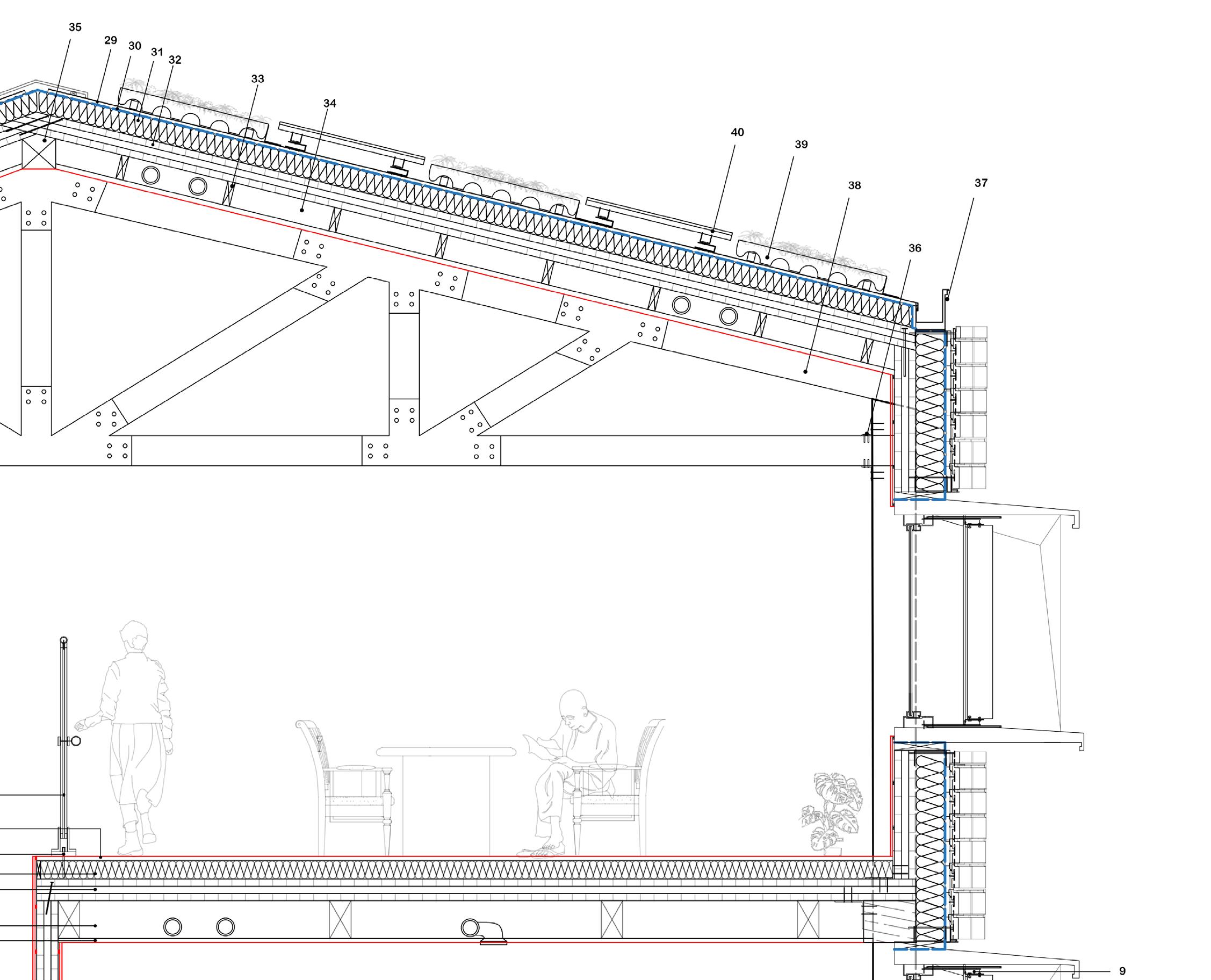
Roof junction detail drawing
8
Part 03
Additional Technical Components
3.1 Sustainability Strategy and Environmental Design - Sun path
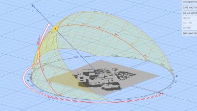
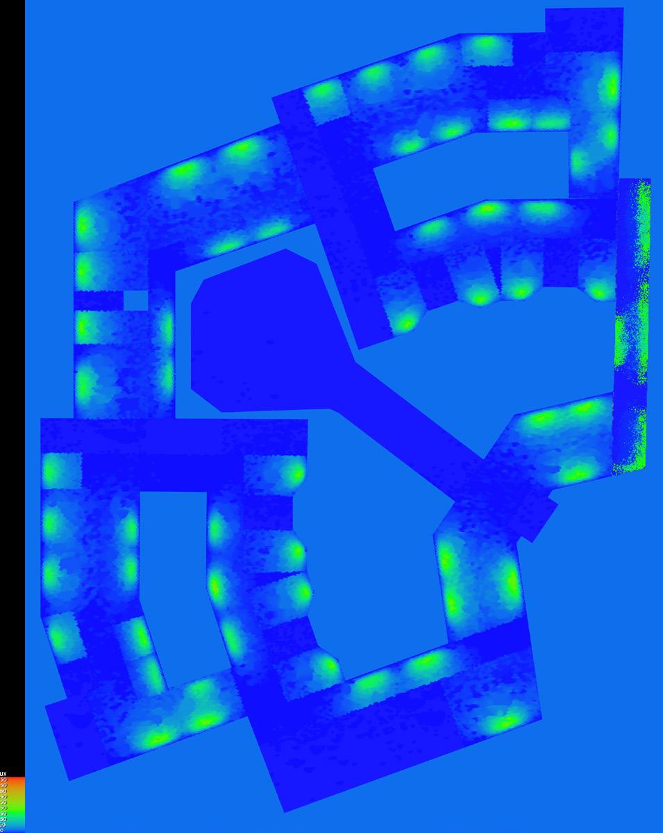
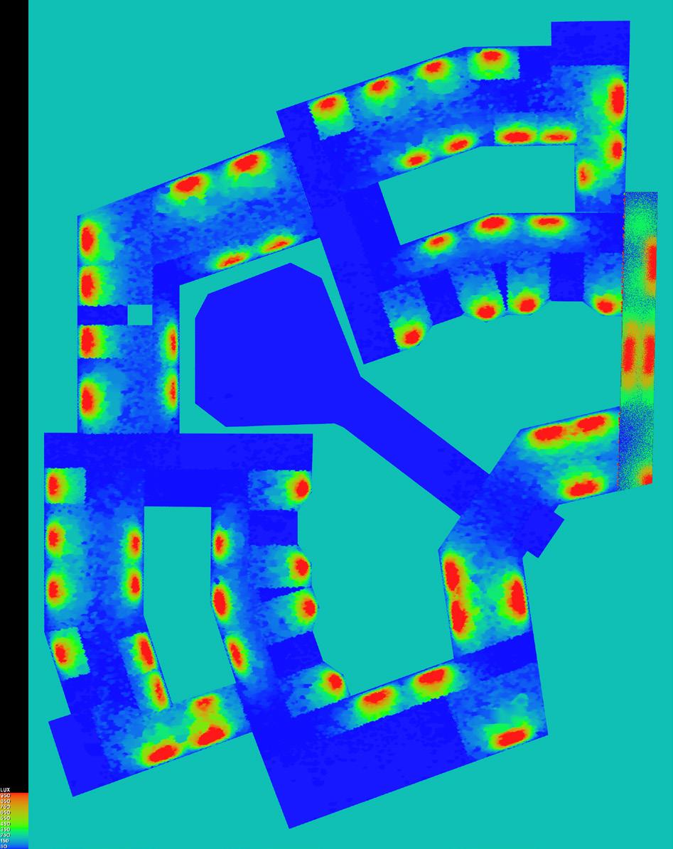
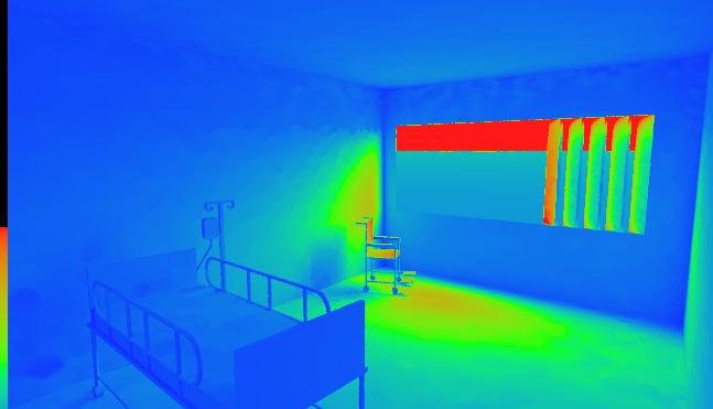
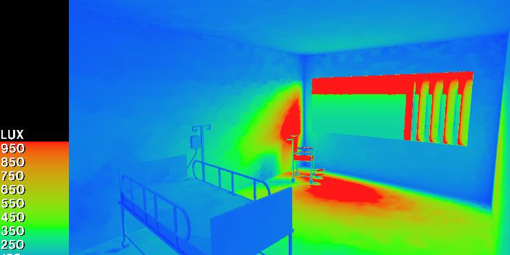
One of the critical natural elements to shape the building form is the sun path. In a dementia care home, interior light uniformity plays an important role to support patients’ daily activities. To respond to this issue, the patient’s pods (wards) are located in the south part of the building to ensure the living space has natural daylight at all seasons.
During the design process, the IES software was used to improve the arrangement of the windows, ensuring the building provides most space natural light during day all year around to reduce energy cost. However, through the simulation, I find there are few room need more light at the midle, this might solve by introduce skylight in my future design
9
Sun path diagram
Massive form diagram
Uniformity simulation on IES, Left: 10am, 30th Dec; Right: 10am, 30th June
3.1 Sustainability Strategy and Environmental
Design - recycled foundation & Rain harvesting
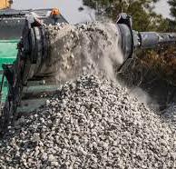
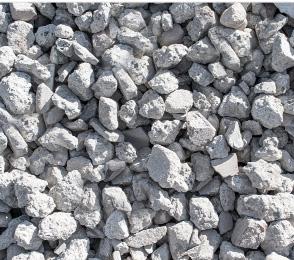
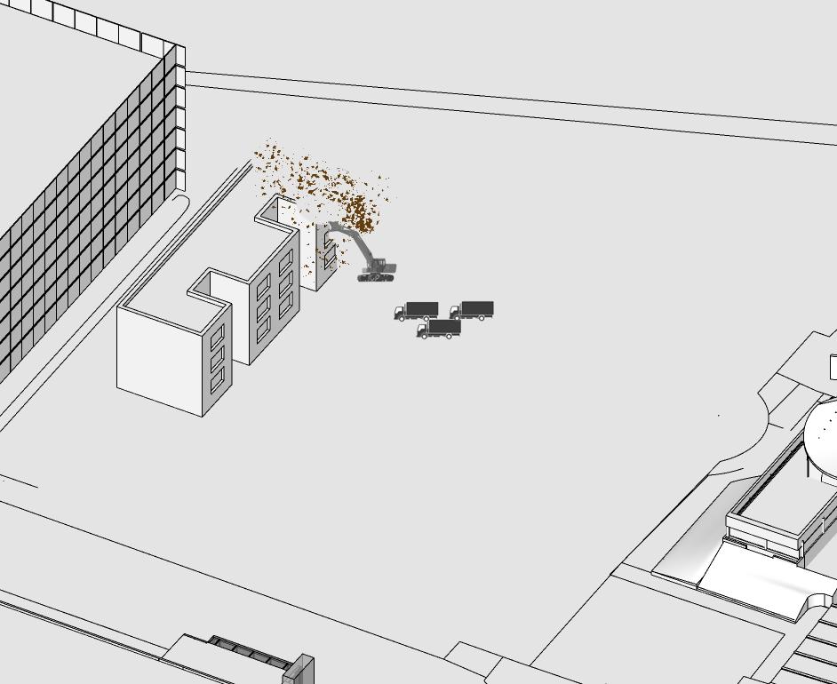
This project would involve demolition work at the site. The building would be demolished as a nurse accommodation, which was mainly built with reinforced concrete. When the building is demolished, the concrete waste would be reprocessed on the site and turned into recycled concrete and masonry (RCM) aggregate, which can be described as graded aggregate produced from sorted and clean waste concrete and masonry. The RCM would be used as a landfill and part of compacted hardcore. This can help reduce the carbon emission by transport and maximum use the construction waste.


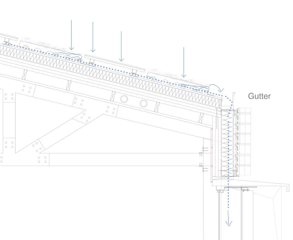
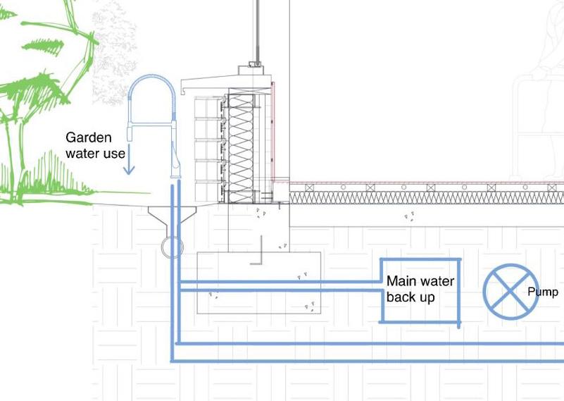
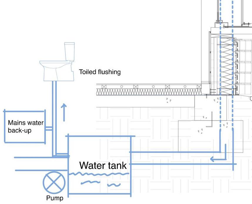
An additional sustainable thought in my design is the rain harvesting system. The vegetation on the pitched roof would slow the rainwater down. The water that split out would run down through the gutter and be stored in an underfloor water tank. This water can provide partially toilet flushing water as well as garden use. However, the main water backup supply could support the daily use when it is needed.
10
3.1 Sustainability Strategy and Environmental
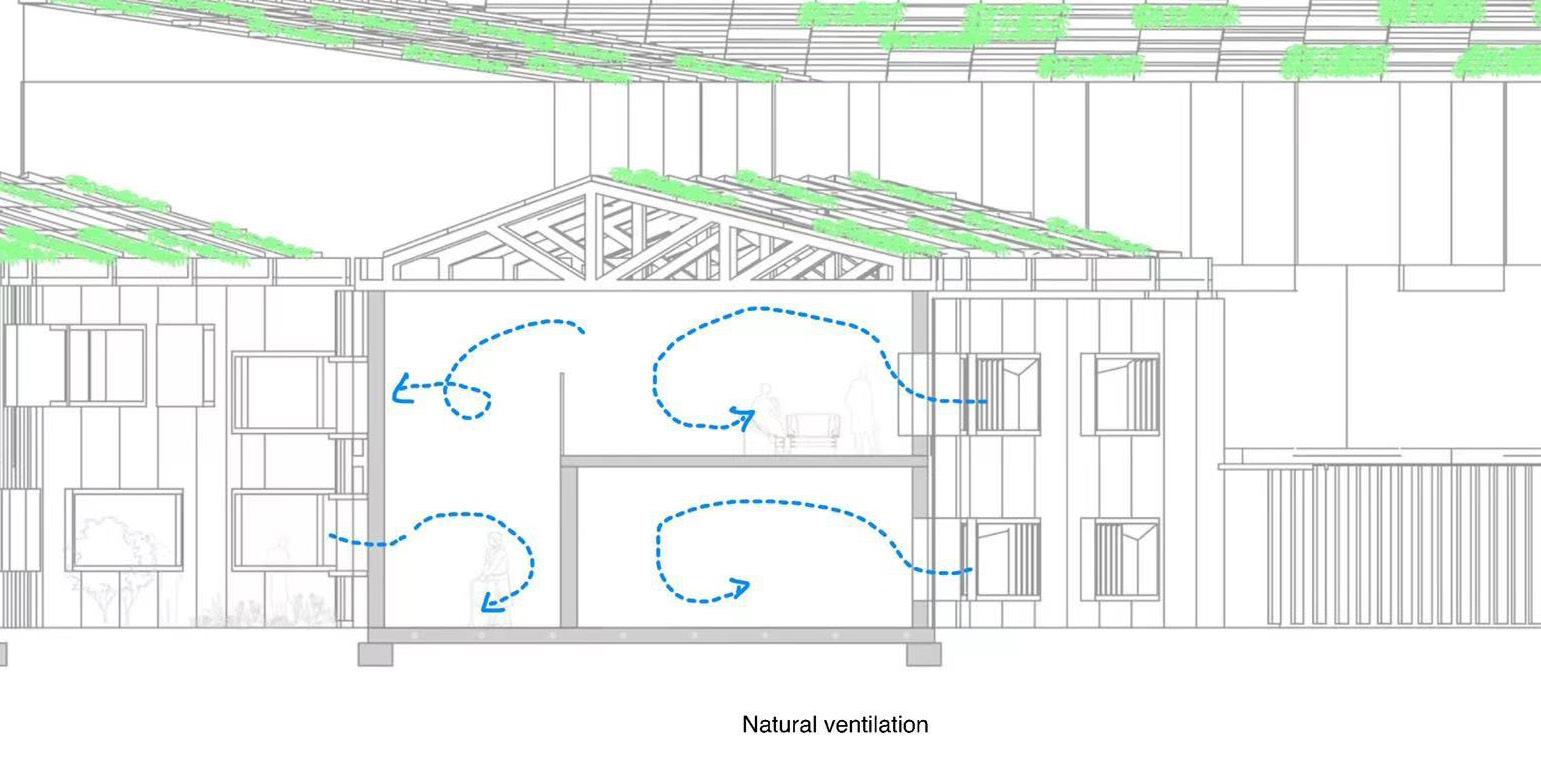
Design - heaing & ventilation
The primary method to ventilate this building is natural ventilation. There are windows on both sides of the building, so the air can form good convection. In addition, MVHR ventilation would provide interior space with fresh and cool air as well as extract hot air.
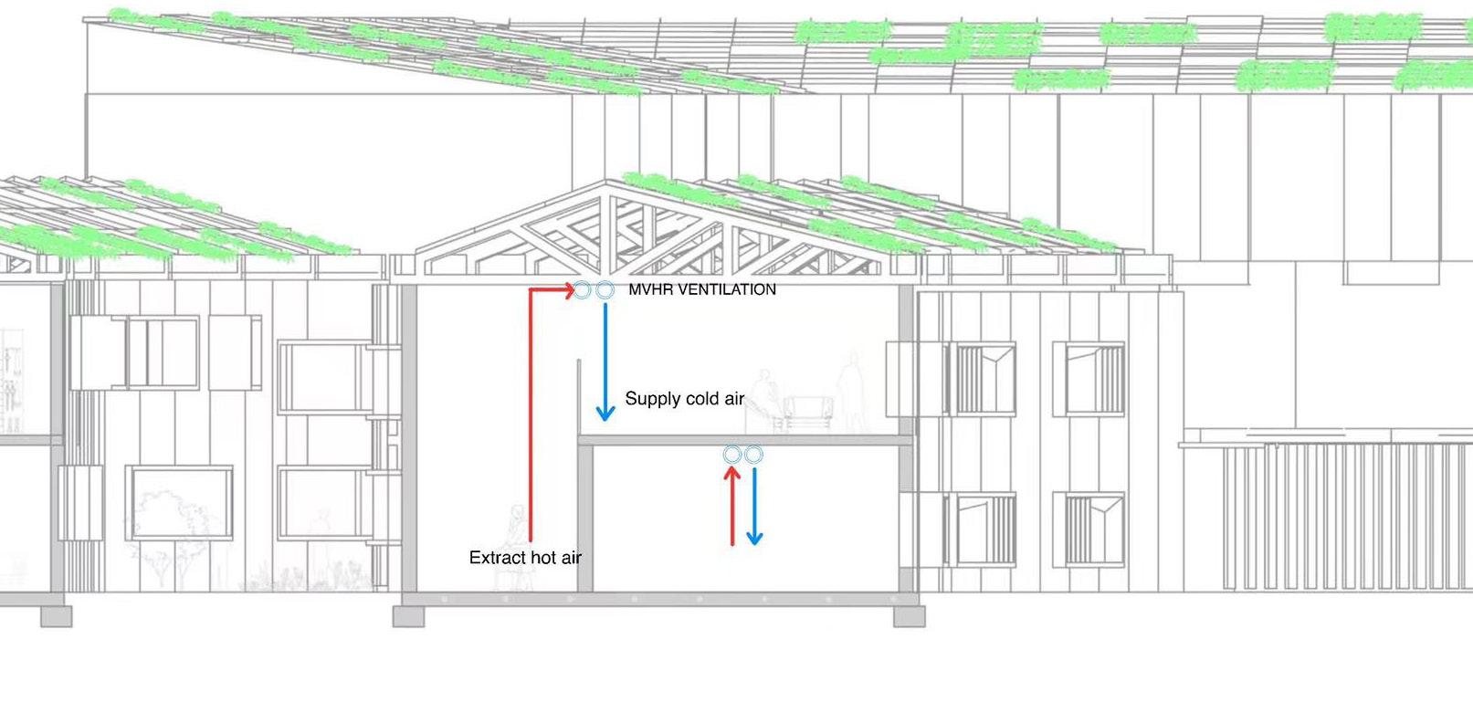
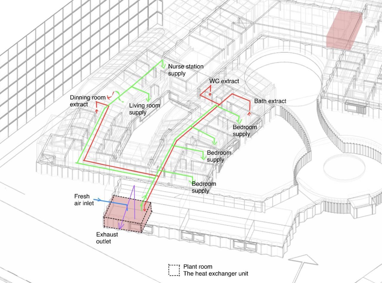
11 Plant room location and MVHR working diagram
Winter
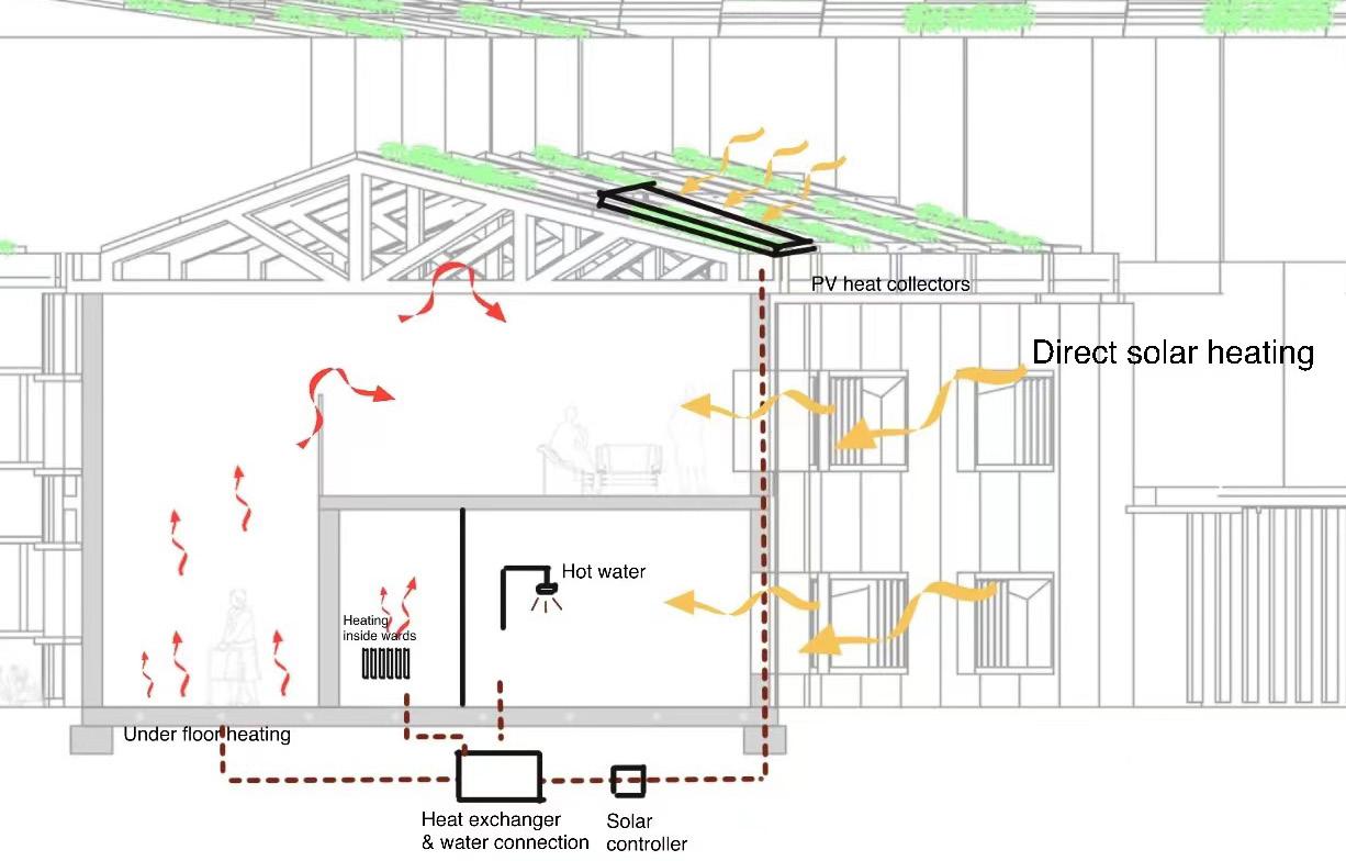
3.1 Sustainability Strategy and Environmental Design - heaing & ventilation
Summer
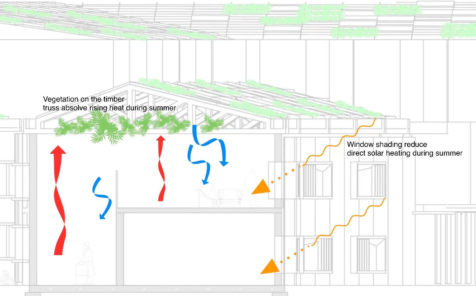
The primary heating energy is mainly natural solar radiation. To ensure the building could receive the radiation at a comfort level in different seasons. The user could adjust the solar shading fins to a certain angle. The underfloor heating would generate heat by the support of roof solar panels, providing additional heating when it is needed. In this case, the building could be self-contained and only consume a small amount of energy to maintain a comfortable temperature level.
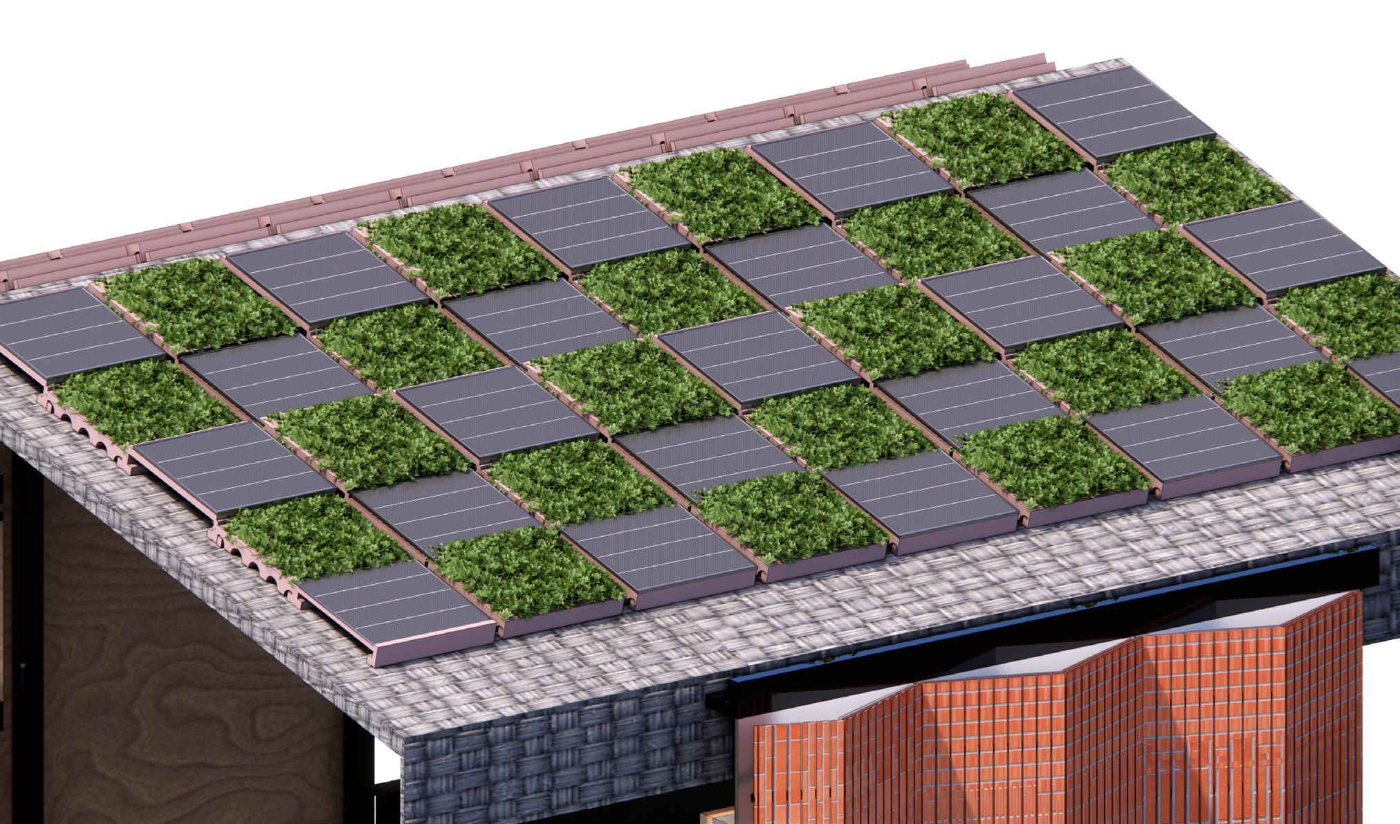
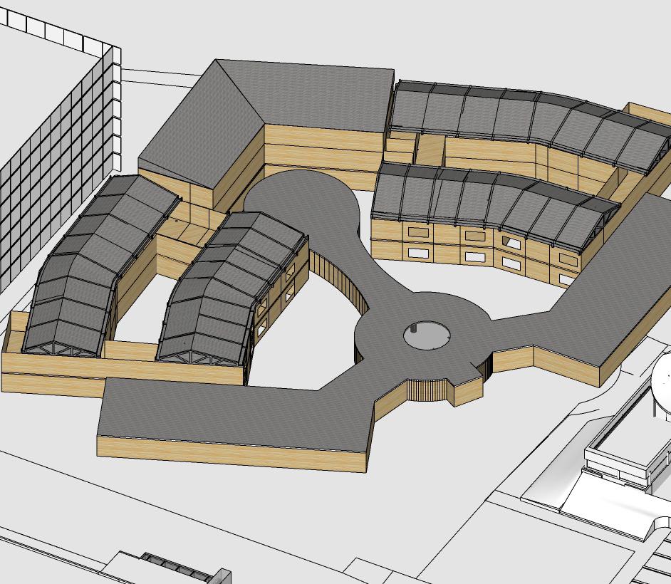
GREEN ROOF AND PV
The roof is designed into a grid frame, which allows the PV and vegetation been placing together, the green roof reduces the temperature on the roof. This would cool the roof. The result would be to improve the efficiency of the PV. The higher efficiency of solar panels can reduce total energy costs.
12
3.1 Sustainability Strategy and Environmental Design
- material choice
According to the ICE database, timber material would emission less embodies carbon compared with concrete and steel. Therefore, the construction material of this project would use timber as much as possible. In addition, timber materials have the lowest waste rate among all the construction material (istructe.org).
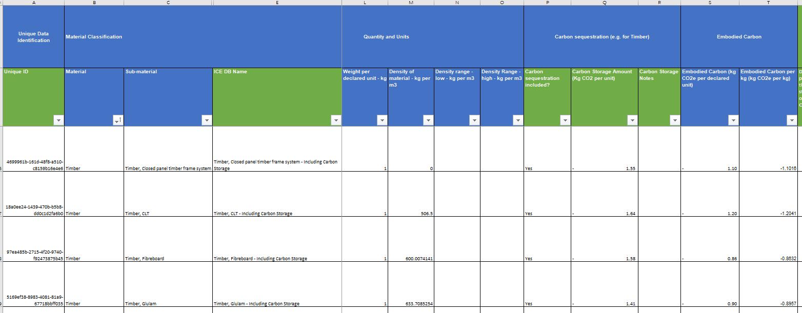
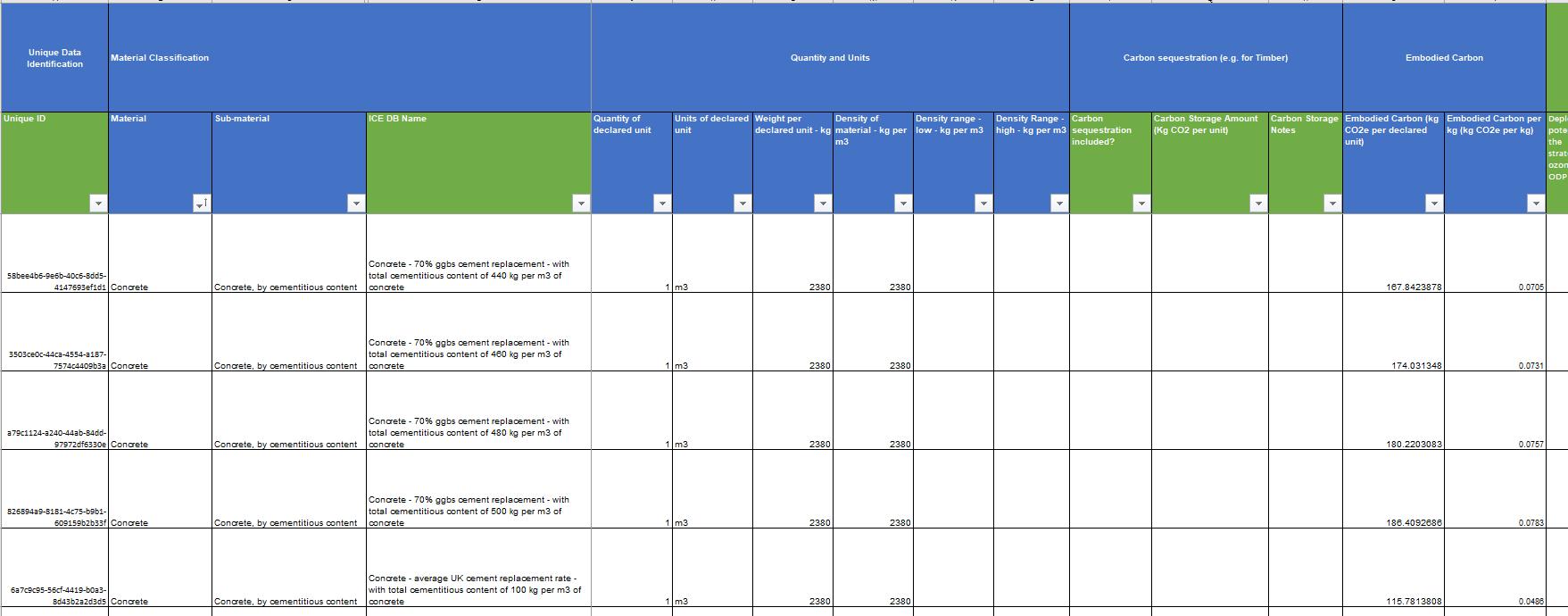
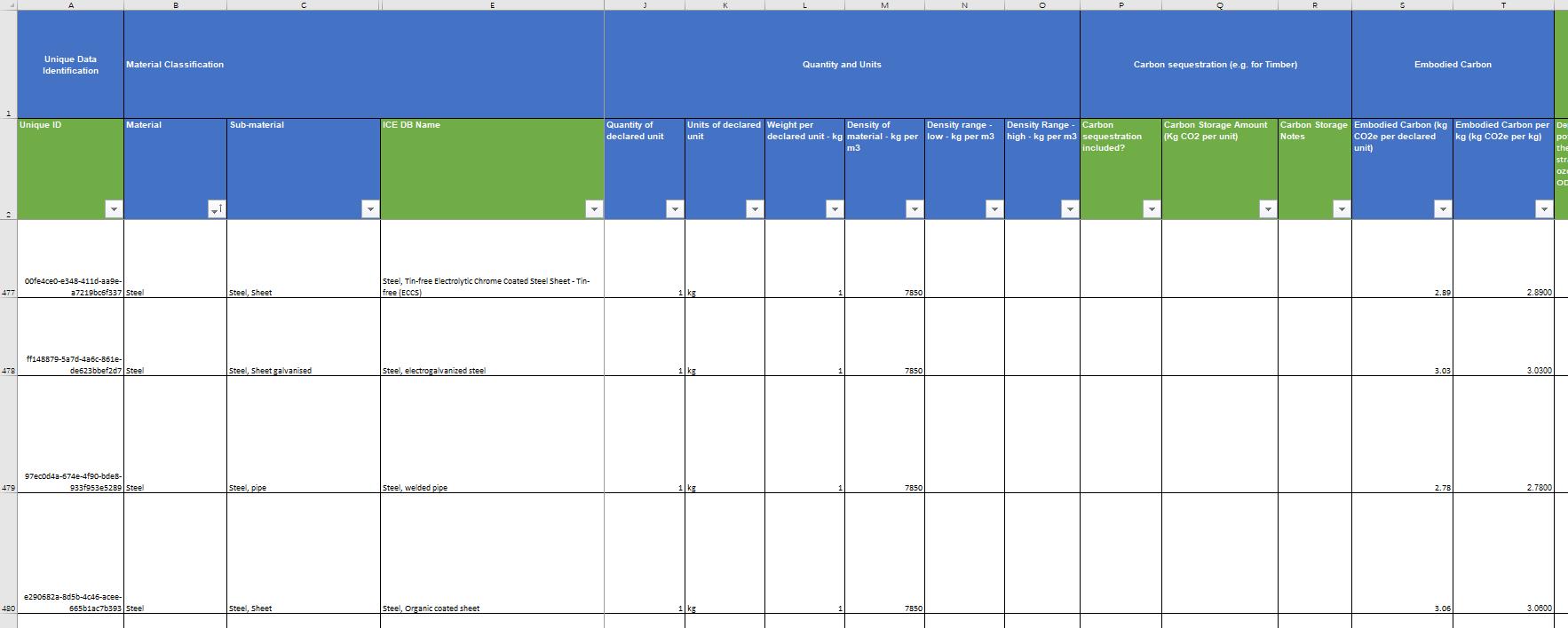
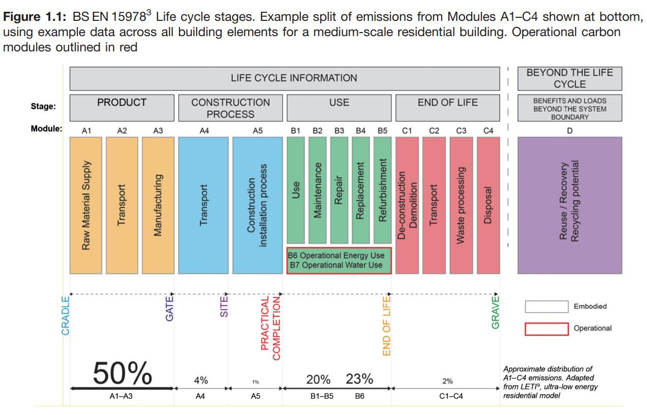
Life cycle stages and material waste rate diagram
https://www.istructe.org/IStructE/media/Public/Resources/istruc te-how-tocalculate-embodied-carbon.pdf
U
13
value calculation: external wall (left), roof (right)
3.2 Structural Strategy and Construction Sequencing
Structure diagram
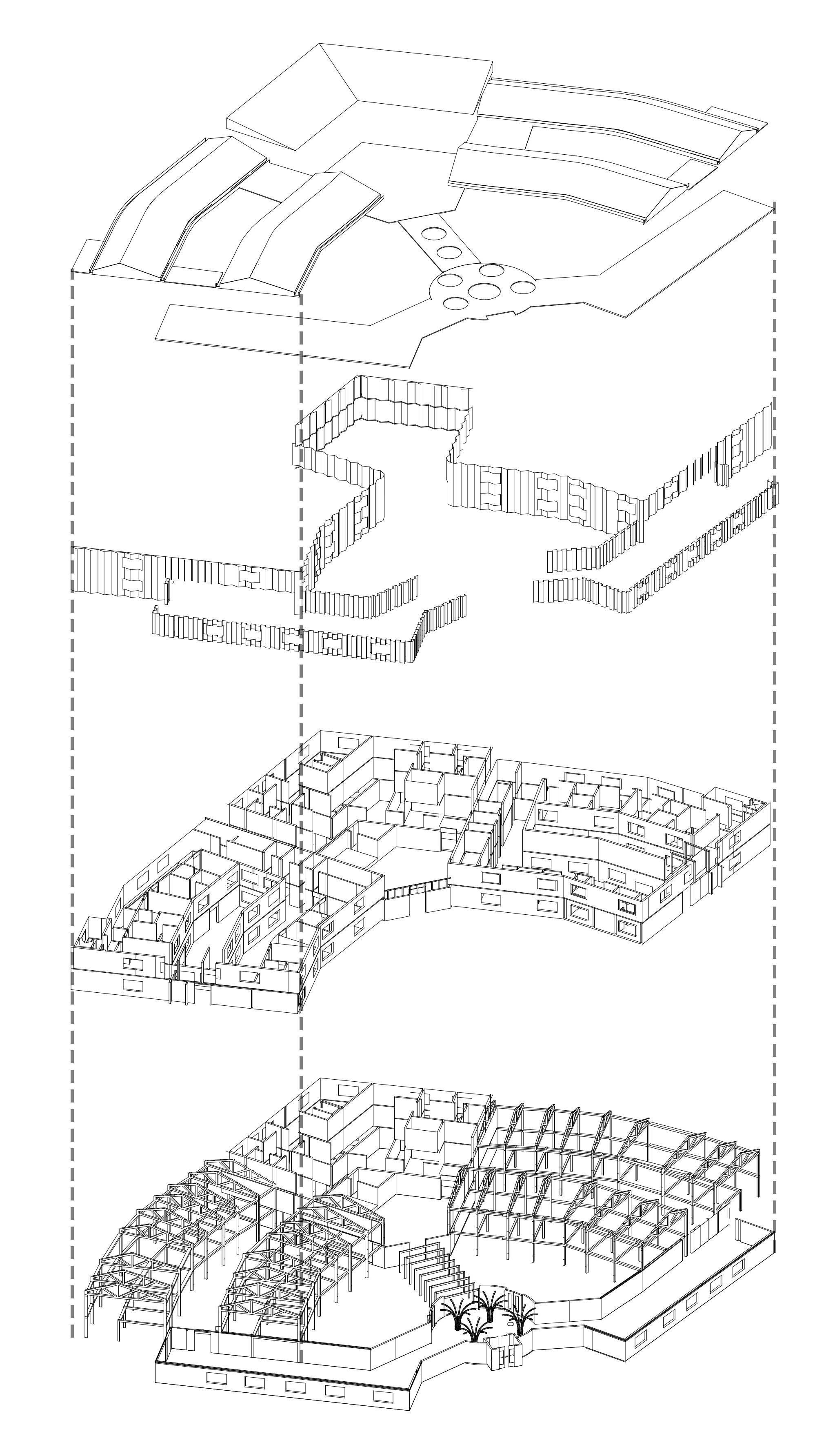
TERTIARY STRUCTURE
-Roof finished: including green roof and PVs
-Facade cladding and glazing windows
SECONDARY STRUCTURE
-CLT floor slab
-CLT interior walls
PRIMARY STRUCTURE
-Concrete foundation and floor slab
-Glulam columns and beams
-CLT structural wall for nursing accommodation section
14
3.2 Structural Strategy and Construction Sequencing
- Detail junctions
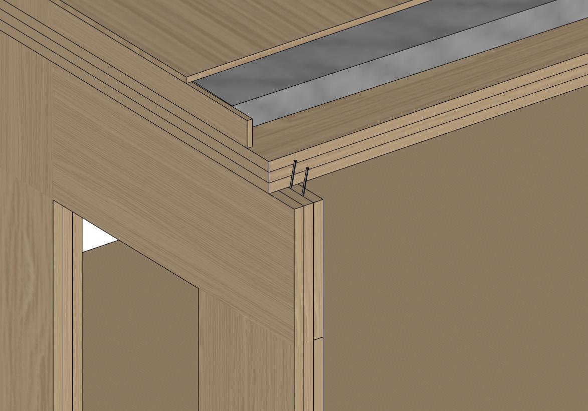
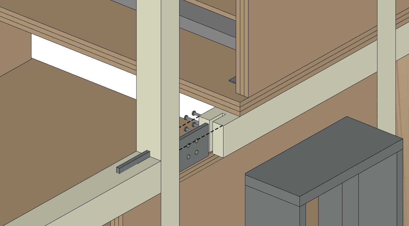
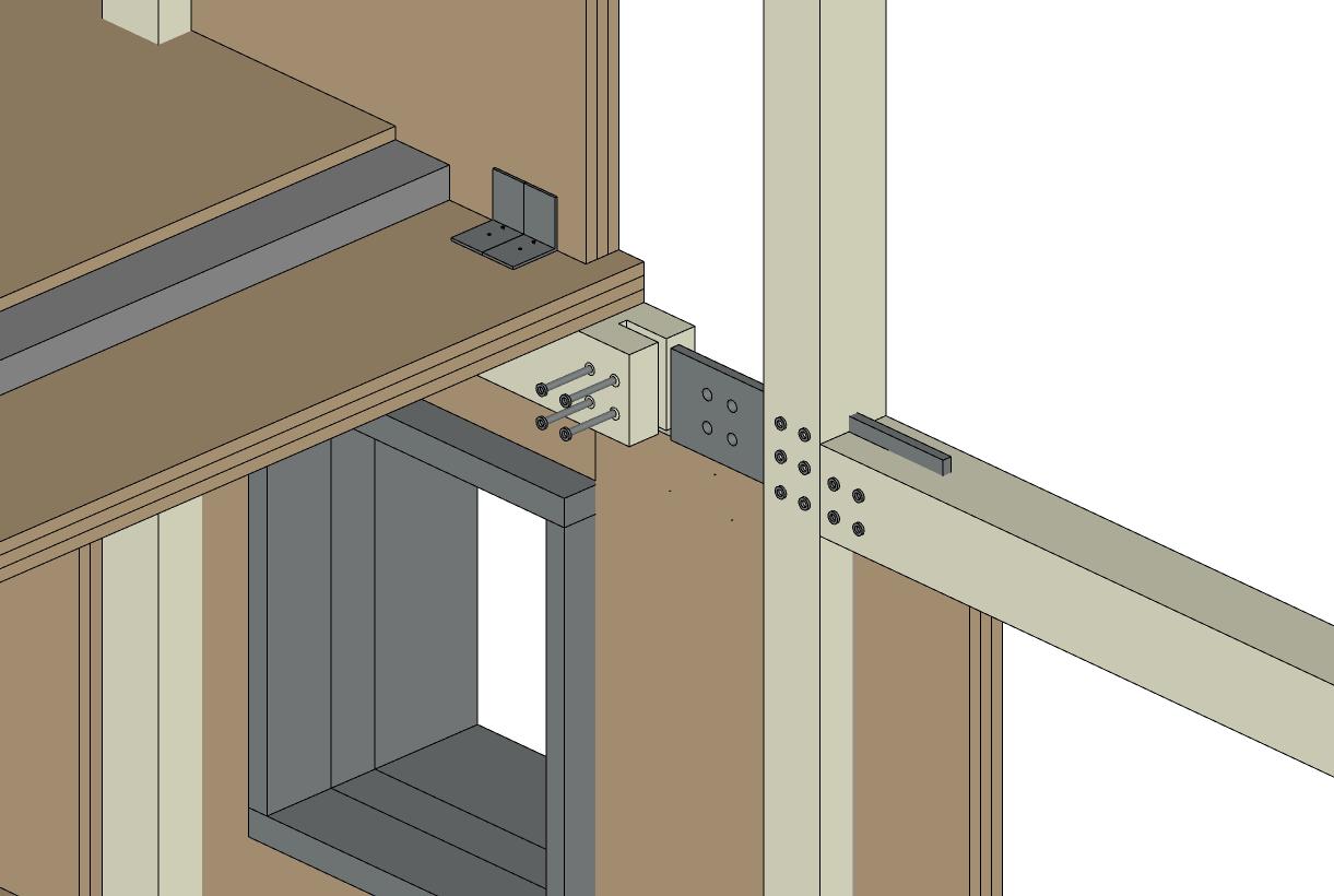
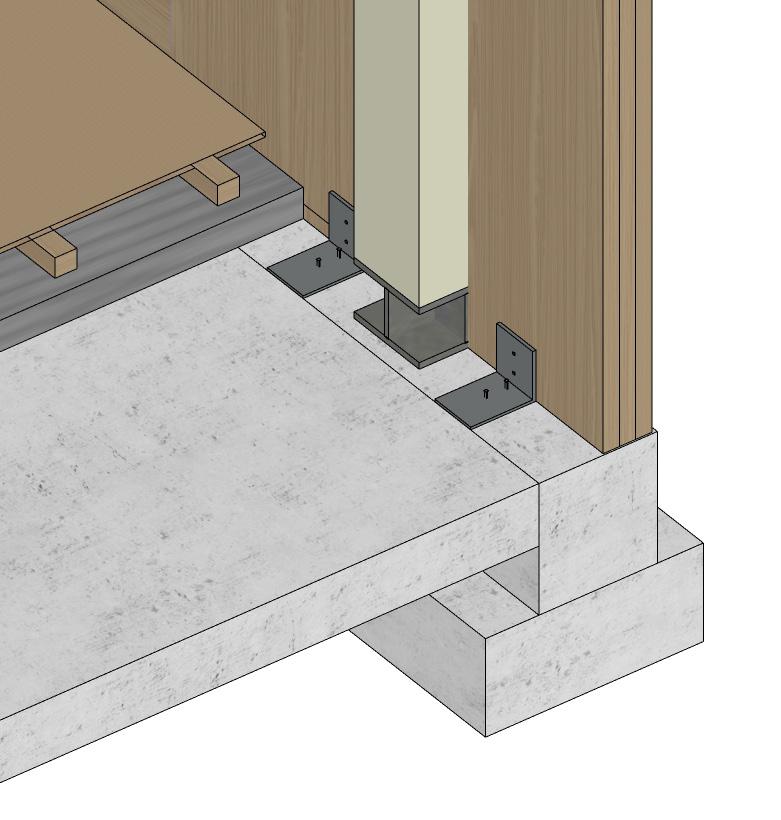
The primary structural glulam column supports the timber truss would be supported by a steel plate footing that seat on the concrete foundation. The junction between column and beam would be connected by an aluminum plate and fixed by a series of bolts. This allows the CLT wall panels to embrace the primary structural frame.
As for the interior CLT floor and wall junction, will be connected using a series of screws. This ensures the CLT stays fixed in place.
15
3.2 Structural Strategy and Construction Sequencing - Build-up process
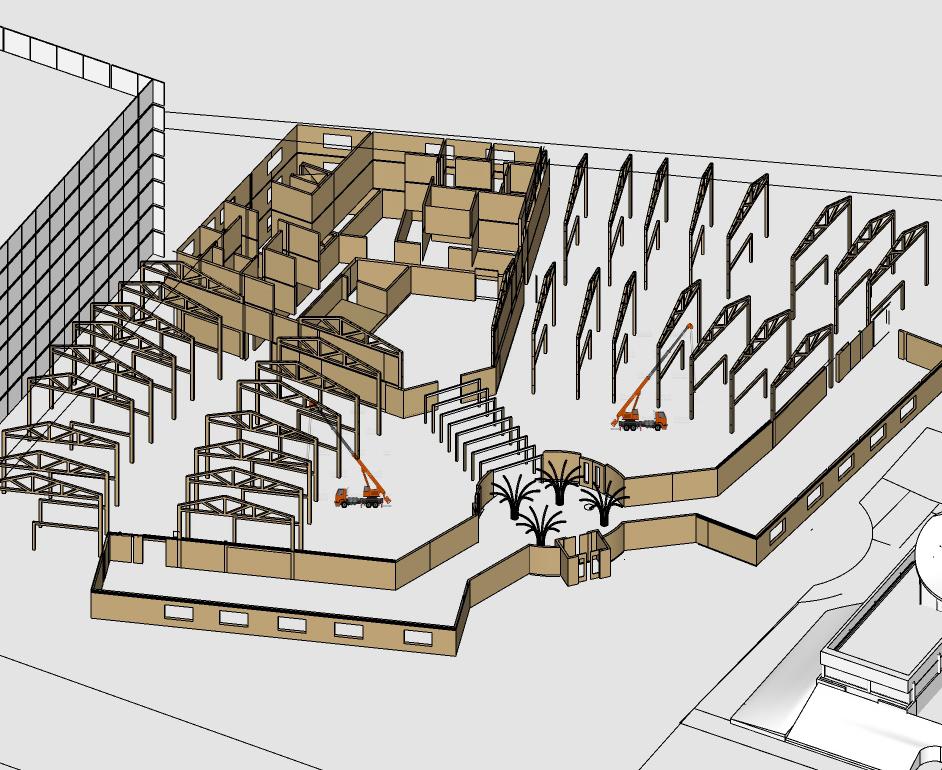
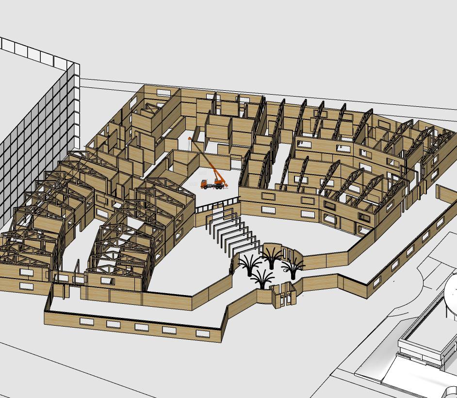
16
1. Demolition job
2. Flat and compact foundation, then pouring concrete
3. Set the glulam structural frame
4. Install CLT floor and wall panels
5. Install roof finishing panels
6. Set additional non-load bearing components, facade layer, window frame, glazing, PV frame, shading
According to the design brief, my project is defined as an assessment hospital. So the fire strategy should follow the regulation of approved document B and HTM05-02.
Occupancy Calculation
Dementia Wards : Per ward
Residents = 8 max
Staff = 8 min
Other staff = 3
Family Visitor = 5
Average Occupancy = 24
Nursing Accomodation
Staff = 20
Visitor = 10max
Average Occupancy = 30
Inter-generational Space
Staff = 10
Visitor = 30
Average Occupancy = 40
Total: 120
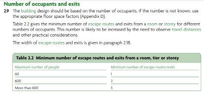
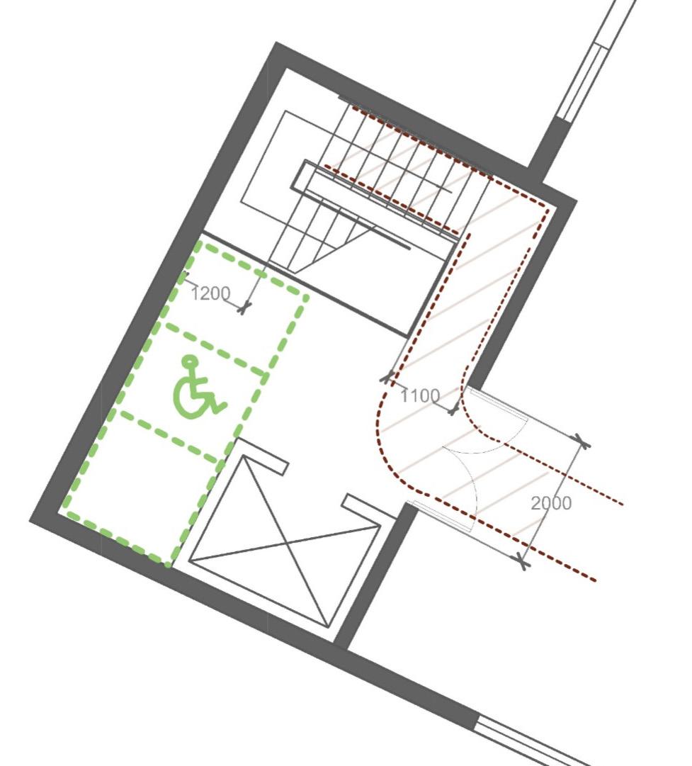
Based on the calculation of average occupation, the building should have at least ONE escape route for each level.
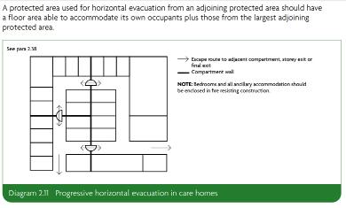
3.3 Fire Strategy - Escape Route design
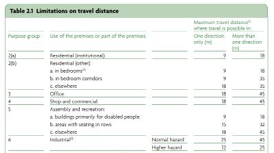
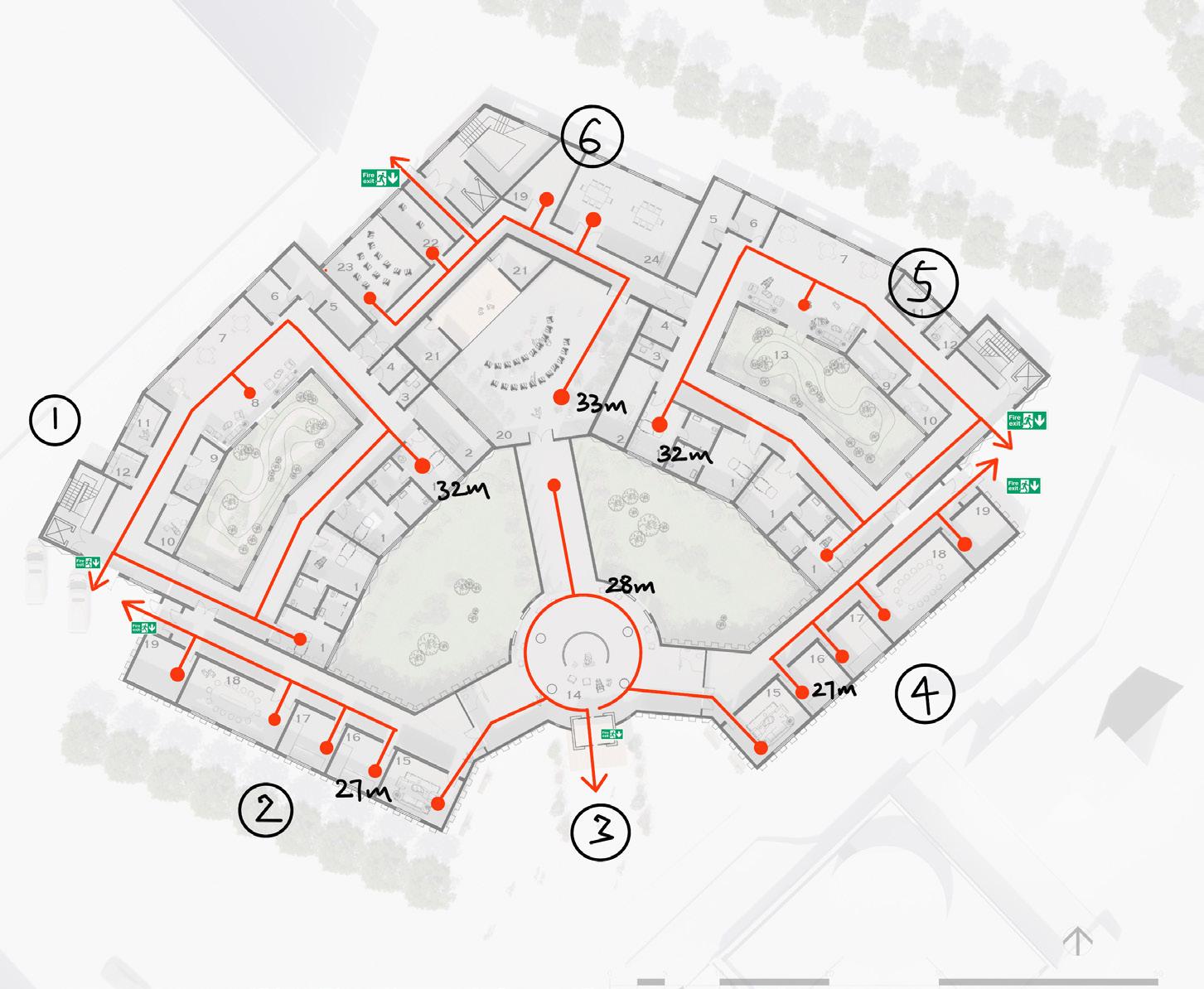
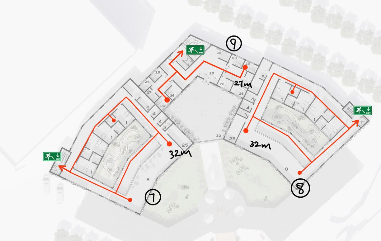

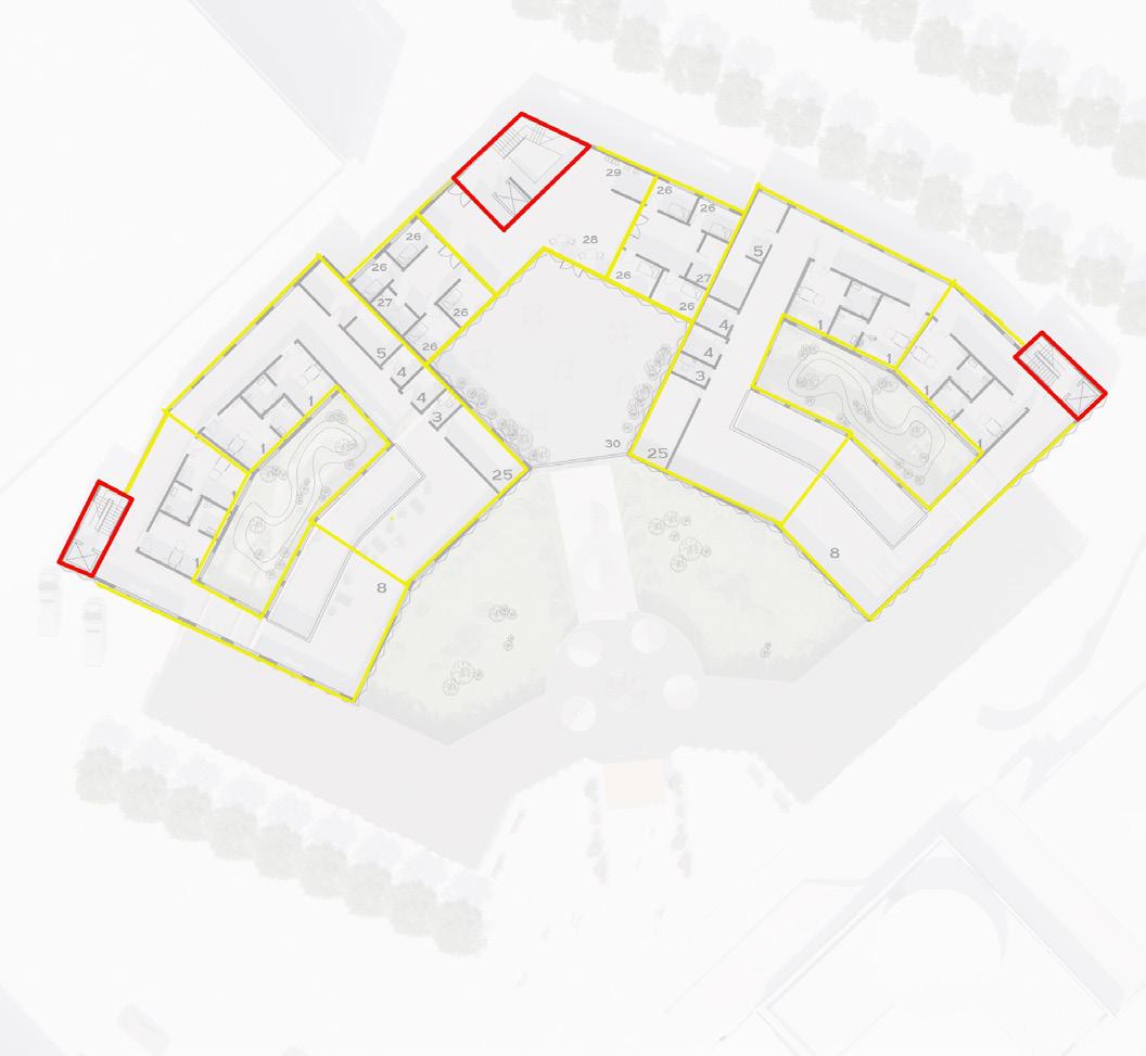
The regulation instructs that the care home should have fire escape routes shorter than 35 meters and shorter than 18 meters from bedrooms.
According to my draft plan, the longest escape route is 33 meters which meets the requirement. However, there are a few bedrooms that have 32 meters route which would fail to meet the requirement. In my future design, I will adjust the location of the bedroom to the north side of the building so the route could be less than 18 meters.
17

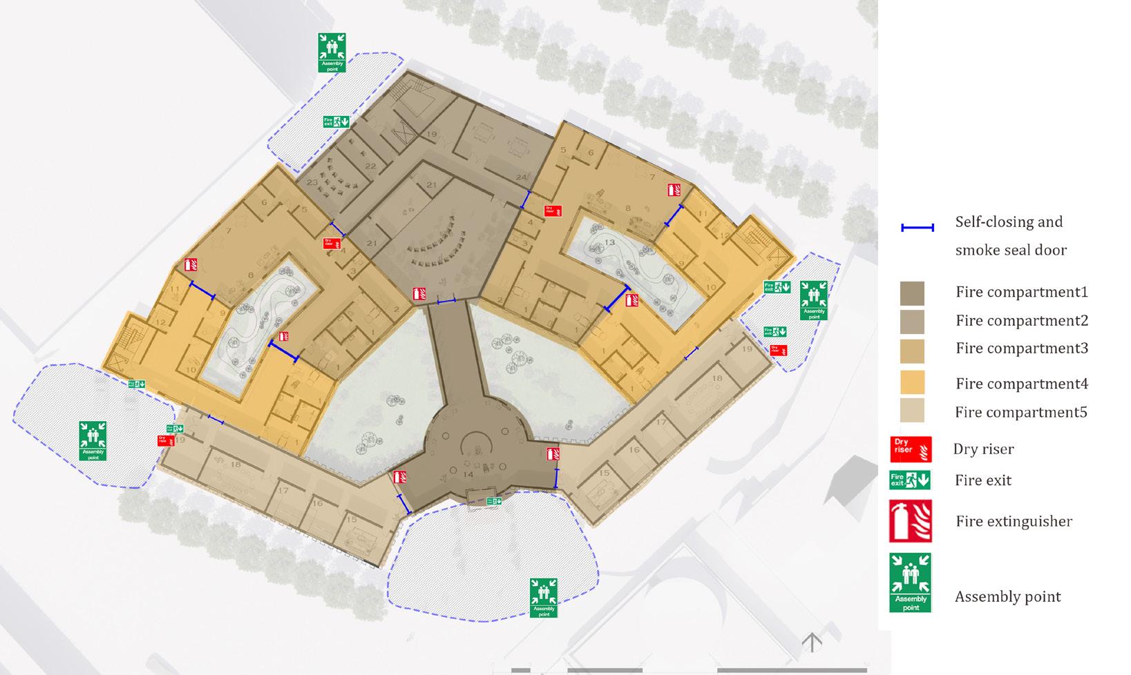
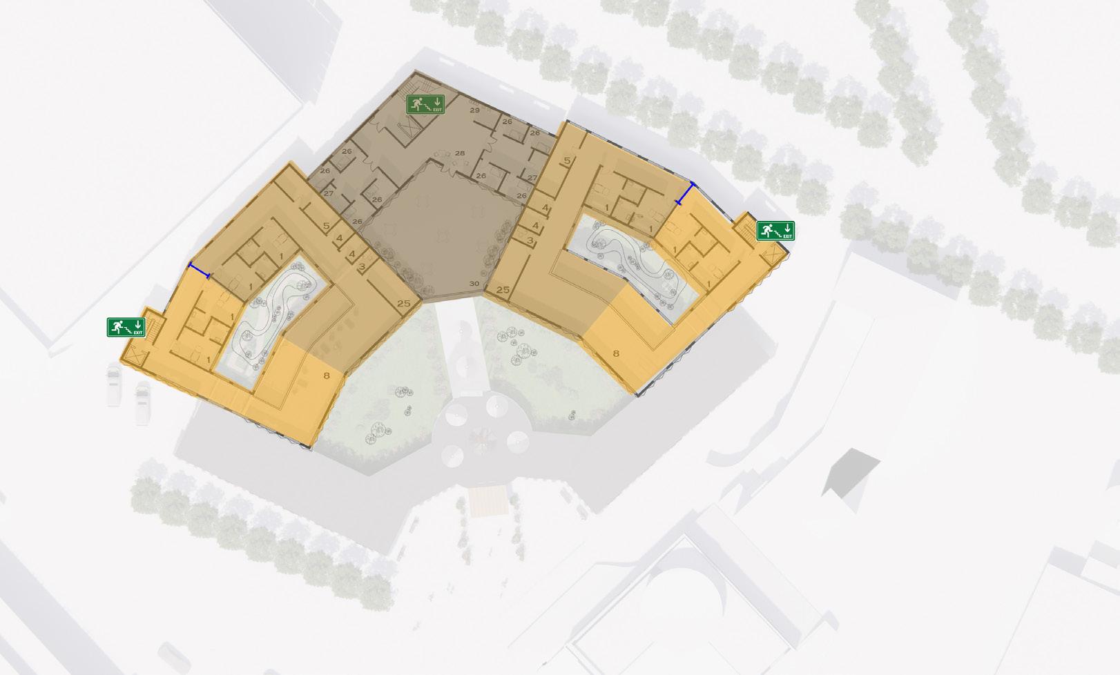
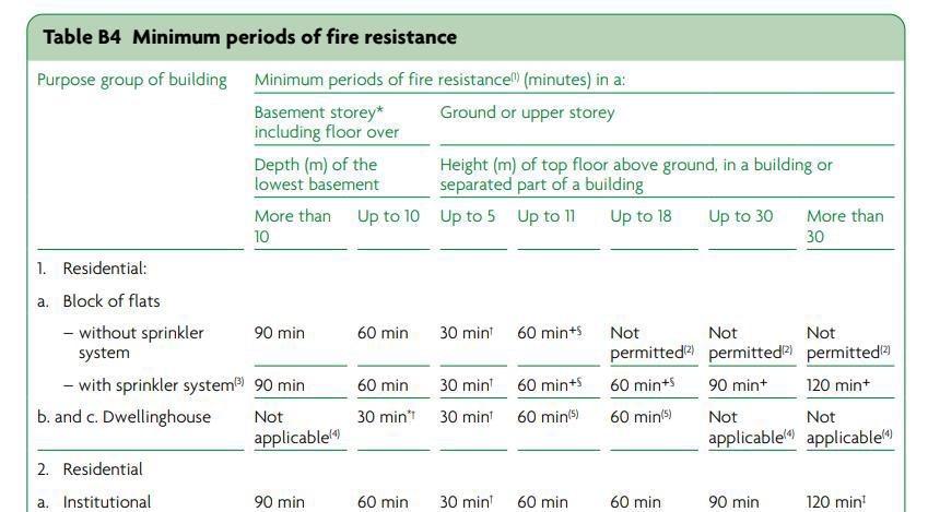
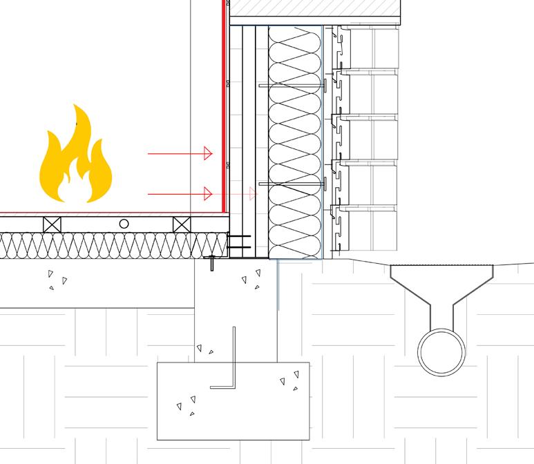
According to the regulation document. this building should at least have 30min fire resistance period time. However, as the users in this building are vulnerable elderly, the evacuation could be slower than normal people. Therefore, spaces with higher fire risk such as kitchens, and important evacuation parts like fire escape stairs would apply higher-level fire resistance material. Similarly, the fire resistance layer could separate the building into different compartments vertically. This would make sure the user on different levels evacuates the building in 30min safe time.
FDS 30min
FDS 60min
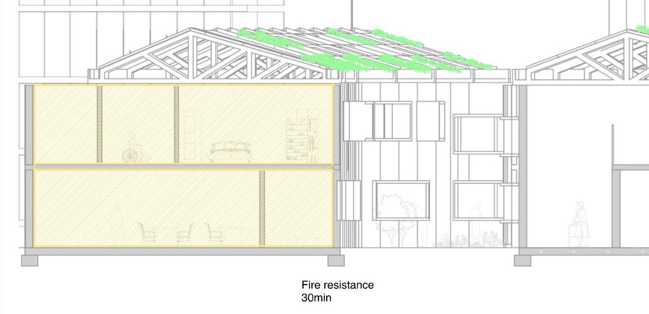
18
fire compartments, dry riser and fire distinguisher location
-compartmentalisation
3.3 Fire Strategy
Vertical fire compartmnets
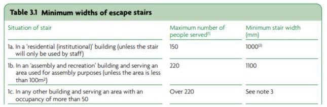
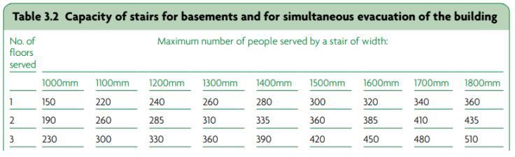
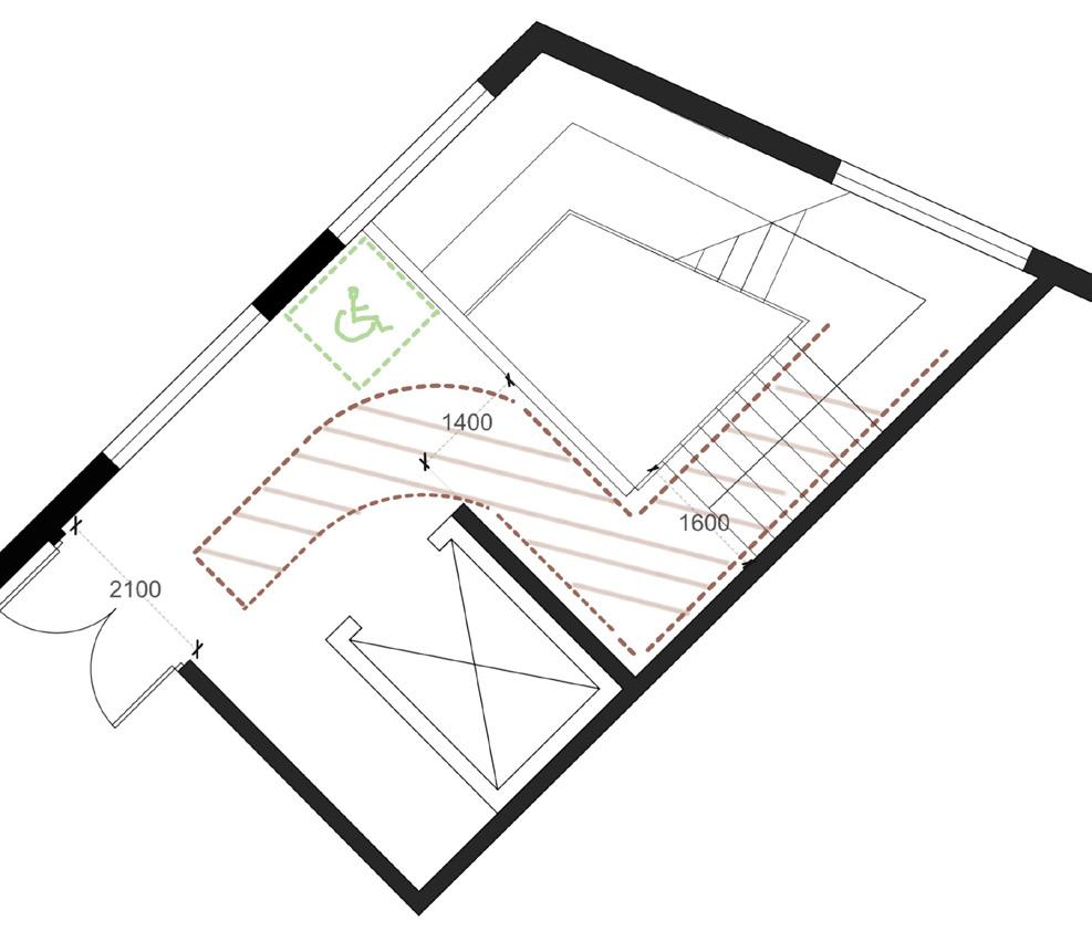
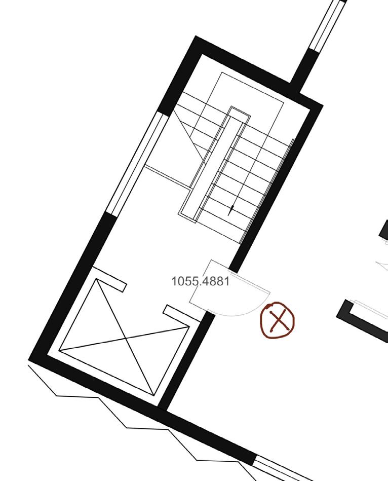
Stairs measurement
Material treatment
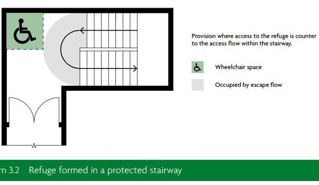
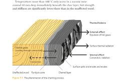
CLT’s fire resistance is provided through‘charring’. As the face of the timber panel is exposed to a fire that ramps up to a temperature in excess of 400 degrees C, the surface of the timber ignites and burns at a steady rate. As the timber burns it loses its strength and becomes a black layer of ‘char’. The char becomes an insulating layer preventing an excessive rise in temperature within the unburnt core of the panel. It is this unaffected core which continues to function for the period of the fire resistance (CLT hand book). Therefore, all the CLT structure interior surfaces would be treated at as a 30min fire resistance layer to ensure the structure frame would not lose the loadbearing function when it has fire, allowing the user evacuate the building safely. According to the regulation, the fire staircase should have space for wheelchair refuge points. The stair in the middle of the building (left) has a larger space than the requirement. However, the stairs located at the wards (bottom left) have not met the requirement of evacuation. I have improved the dimension of the stairs to meet the requirement.

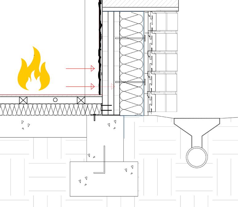
19
1050.0000
3.3 Fire Strategy
Part 04
Studio Specific Technical Research
The dementia progression usually evolves visual misinterpretation. This might include agitated by shadow on the floor, dark space etc. Therefore, this project gives the design work an opportunity to explore the light performance. My tectonic research is main focus on dementia friendly architecture language which covers the elevation study and interior spatial quality.
20
4.1 Visual assistance for dementia sufferer
- Interior space
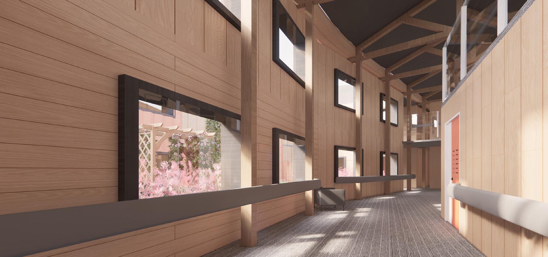
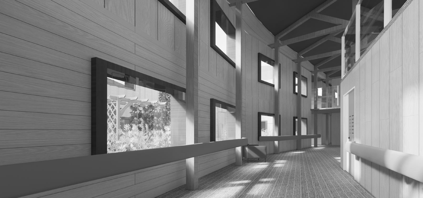
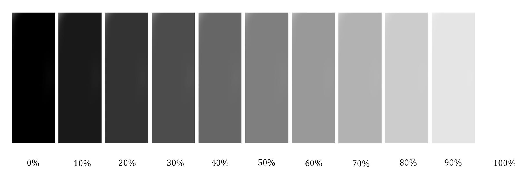
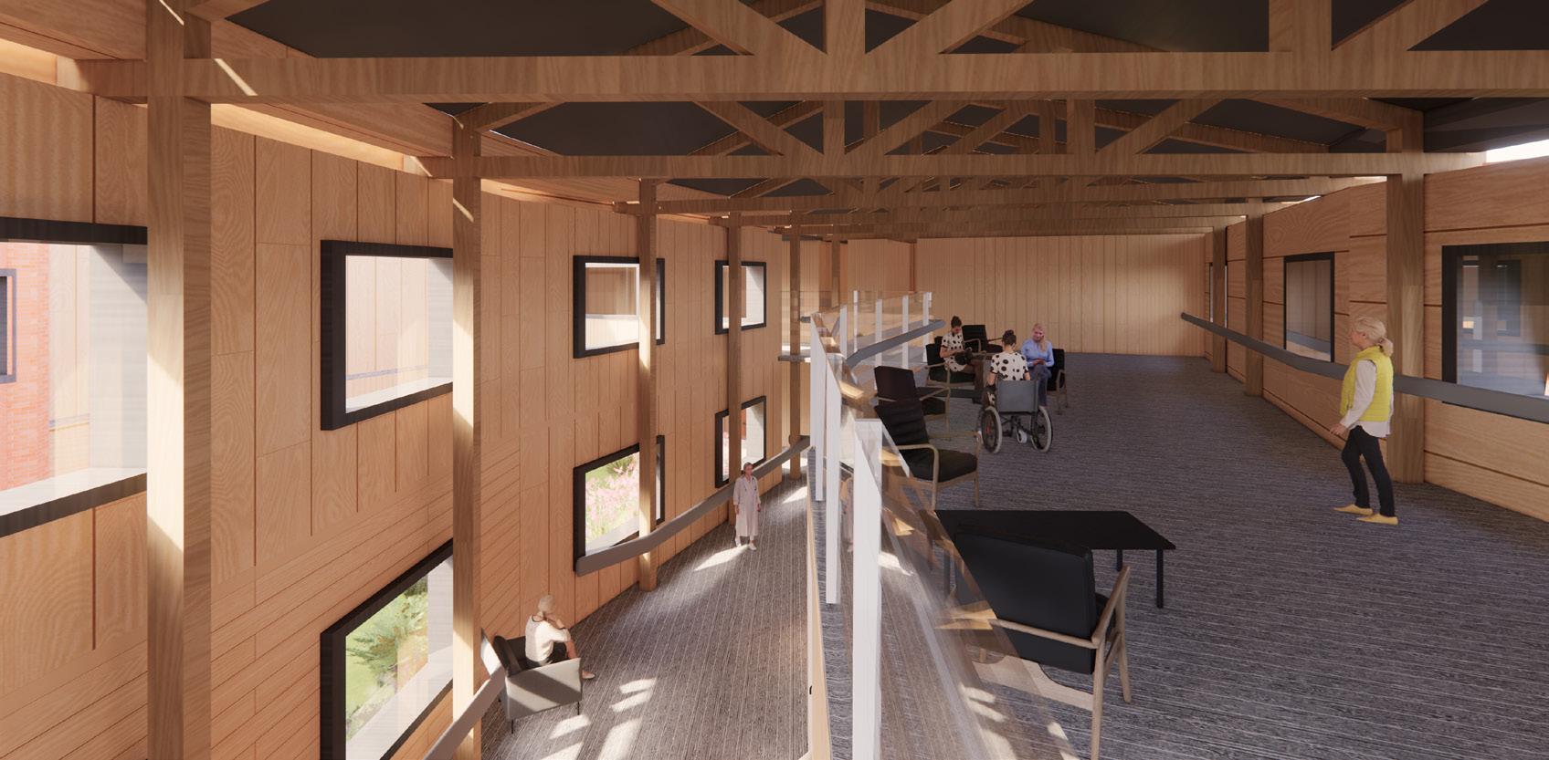
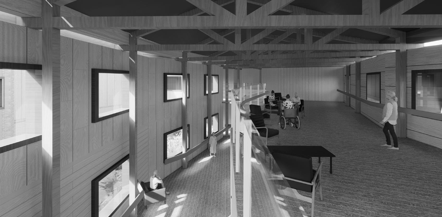
The key interior elements of the wards such as walls, floor panels, and furnishers are kept at 30 percent light reflection value to assist dementia patients to orienting and recognising objects. To ensure this point, normal people should examine the interior render photos by turning photos into black and white mode.
21
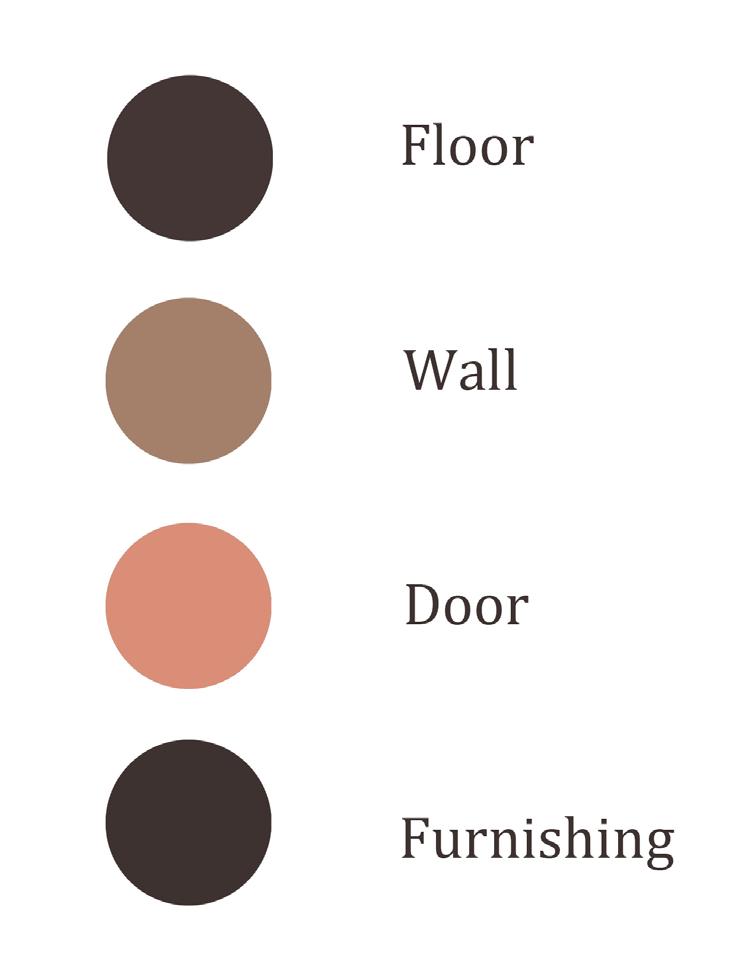
Color contrast between panels
4.2 Visual assistance for dementia sufferer
Elevation study
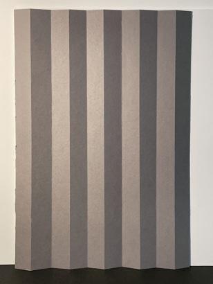
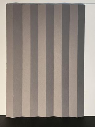
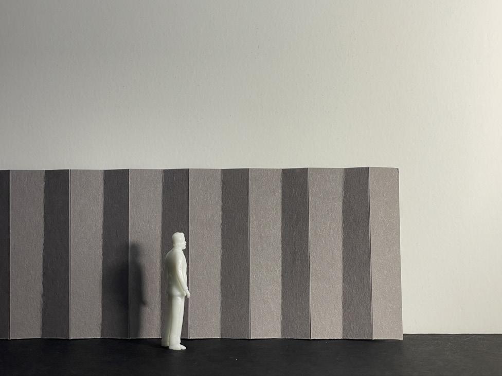
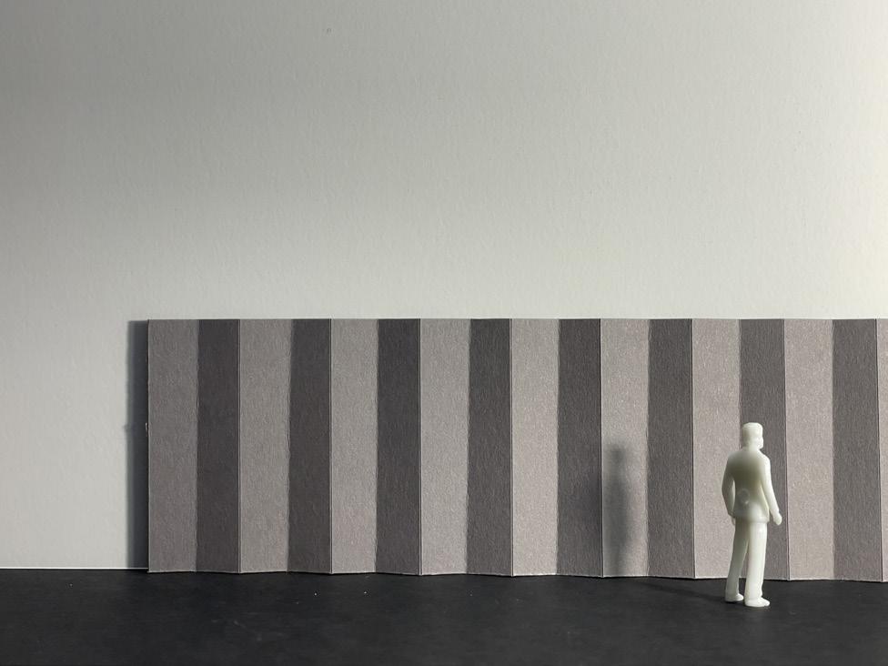
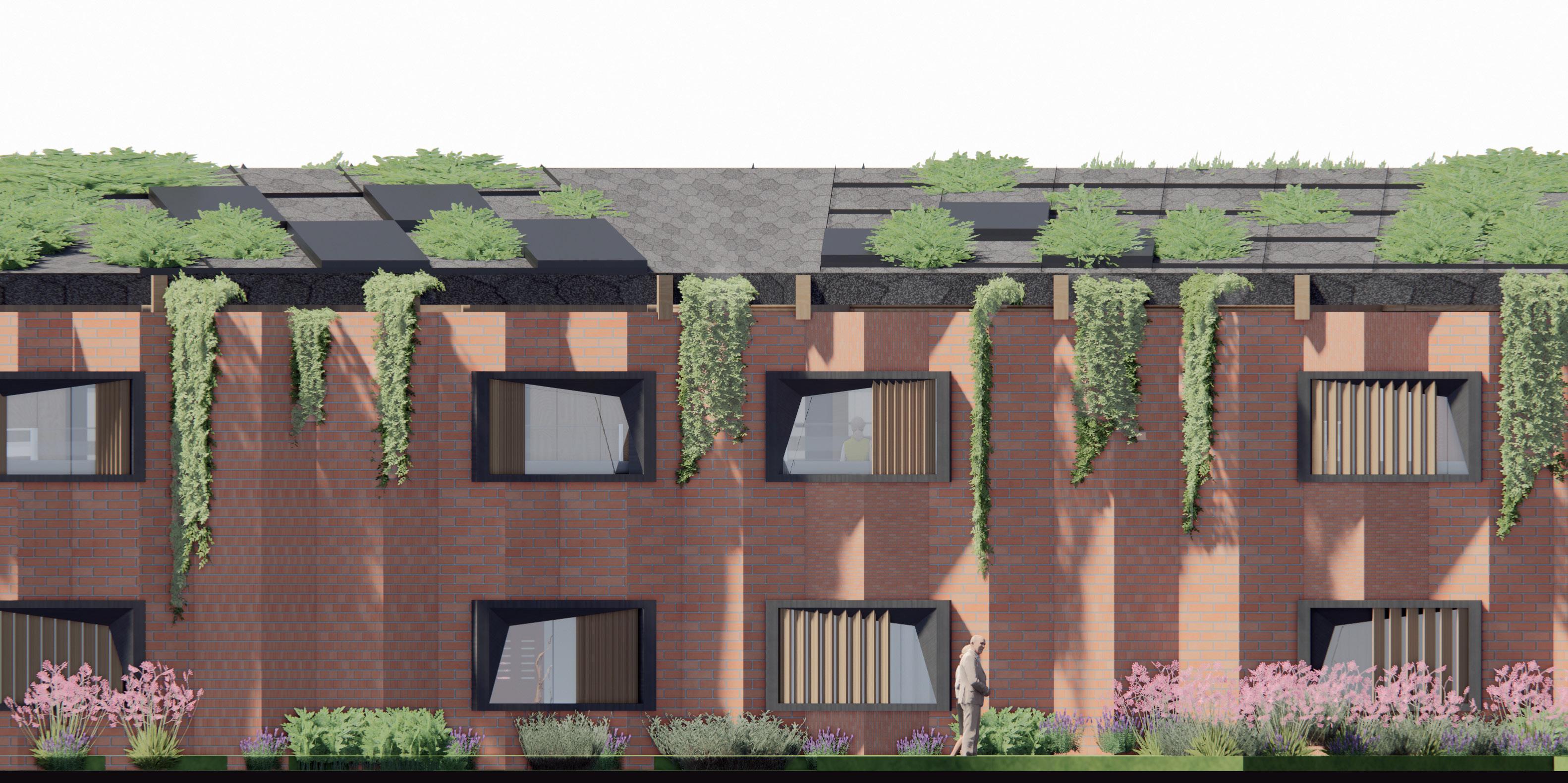
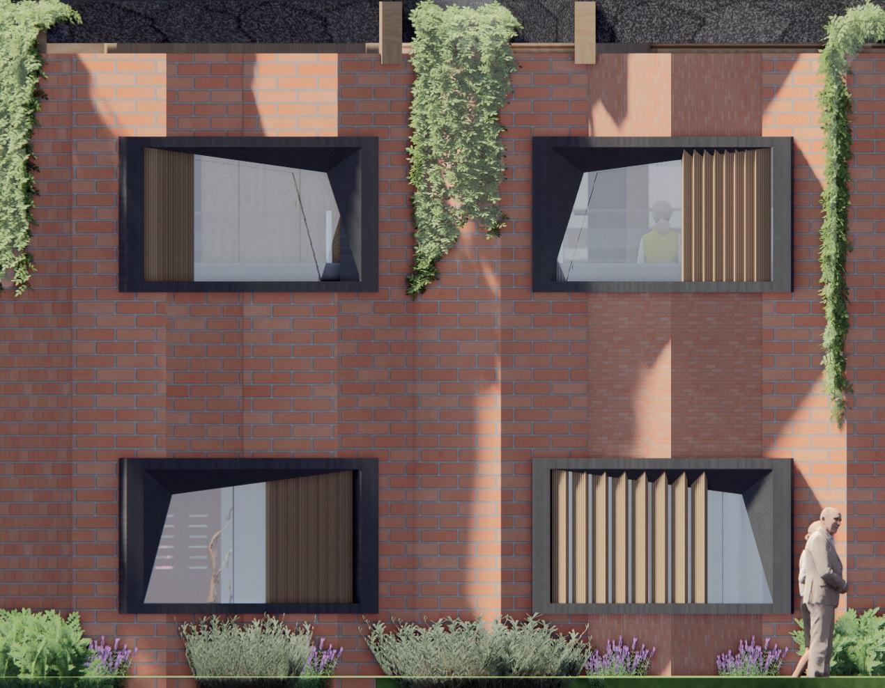
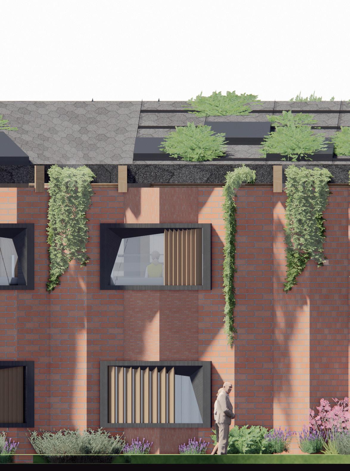
Zigzag brick facade
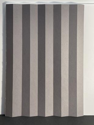
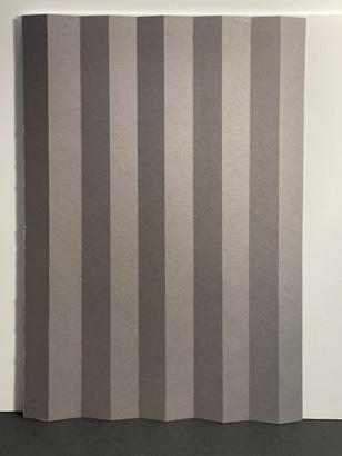
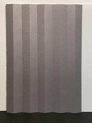
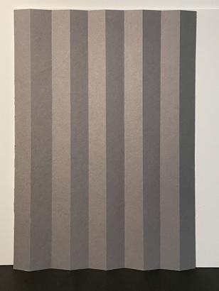
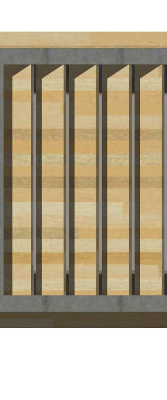
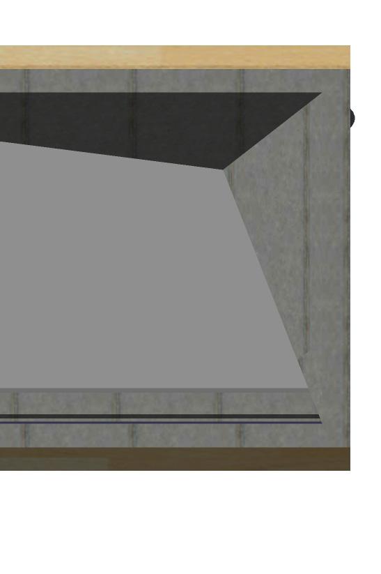
The reason for chosen form of this facade is the light performance of this elevation. It could generate different shadow shapes from different sun angles. This would help dementia patients to recognizing time. With the help of corium cladding, the facade could have an opportunity to be a part of therapy assistance. It could generate a building surface color that has a higher purity that could help people living with dementia recognize the object on it. The color of the window frame would be painted black to create a sharp color contrast to support and enhance dementia suffers’ visual interpretation.
Additionally, the window frame would be prefabricated into a certain shape, which would provide an enhanced light projection on the building elevation, supporting dementia suffering from recognizing the surrounding environment.
22
-
Physical model showing the light projection by various angle.
4.3 Visual assistance for dementia sufferer
- Solar shading
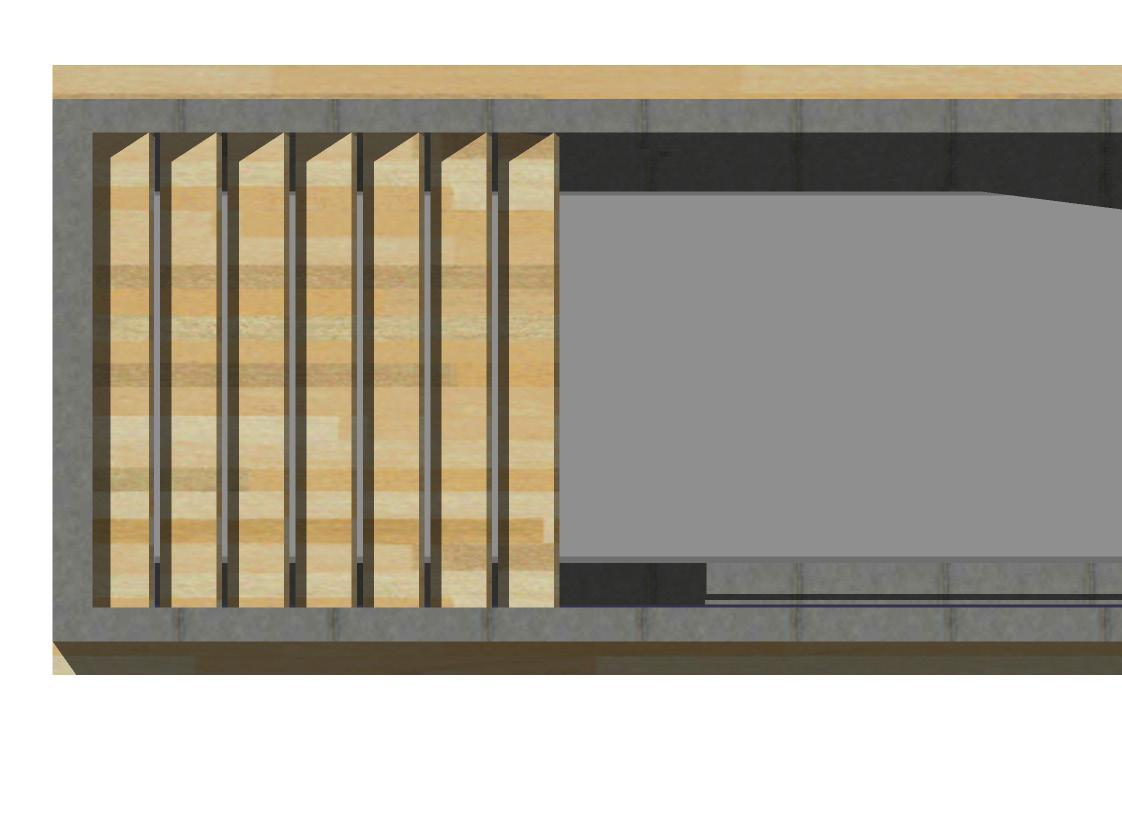

To avoid the generation of shadow and cause misinterpretation, the design of the patients’ ward is applied with solar shading fins to reduce the direct sunlight. However, by using ISE to simulate luminance levels in the wards, the shading failed to achieve satisfied uniformity during the summer (top right). This was improved by creating adjustable shading timber fins to cover the whole window responding to different seasons (see detail plan).
23
Jan 12:00 luminance level
1st
4.4 Interior spatial quality
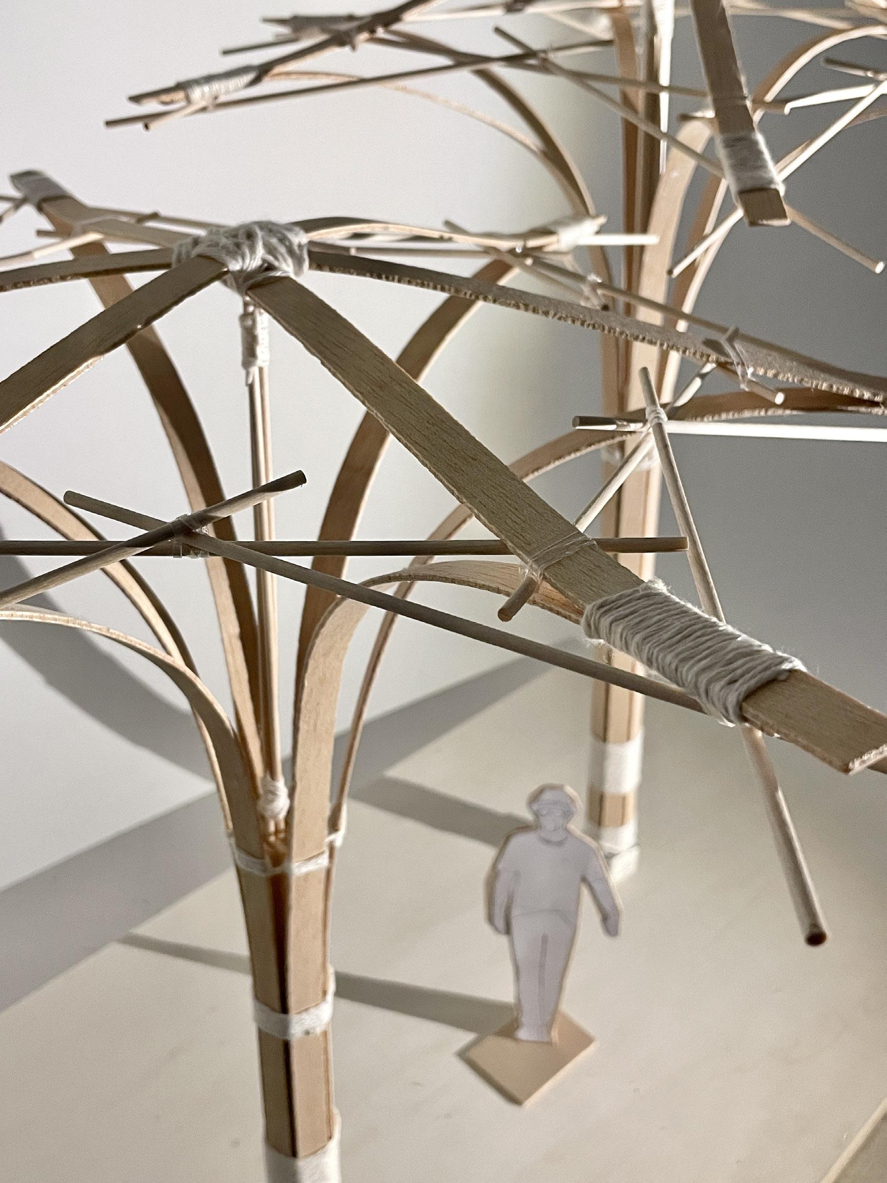
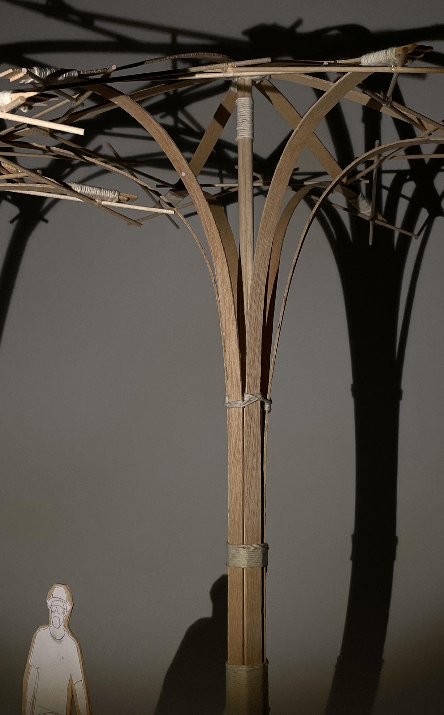
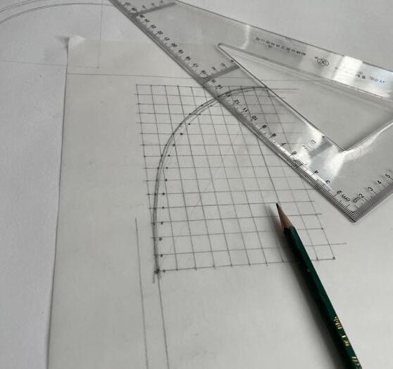
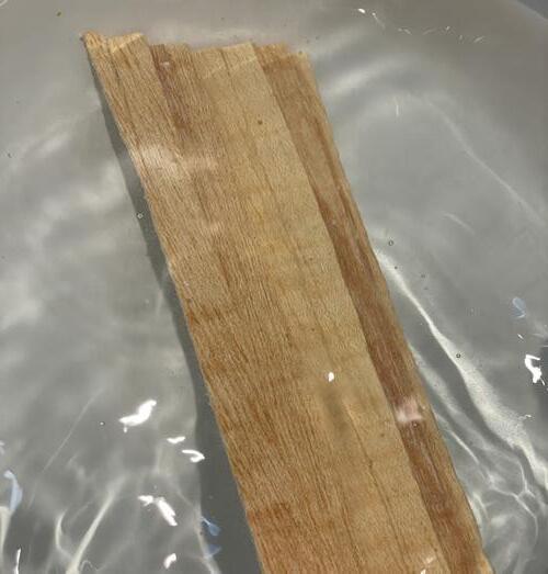
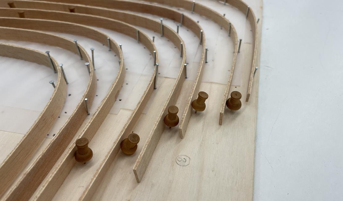
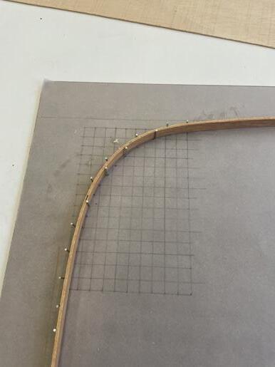
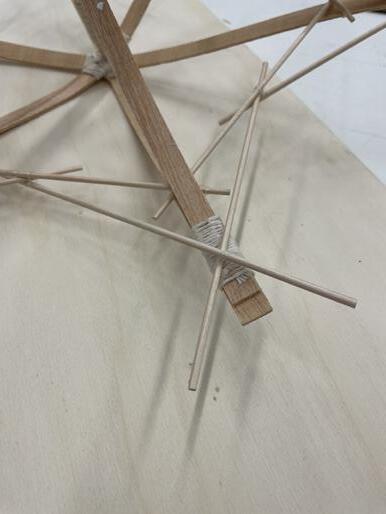
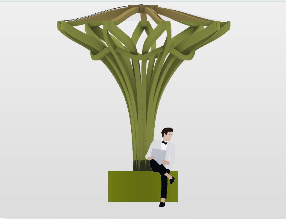
Timber column exploration on Think Through Making exhibition
This model provides me a chance to explore the timber bending technique. Surprisingly, the bent timber could still provide enough load-bearing ability.
24
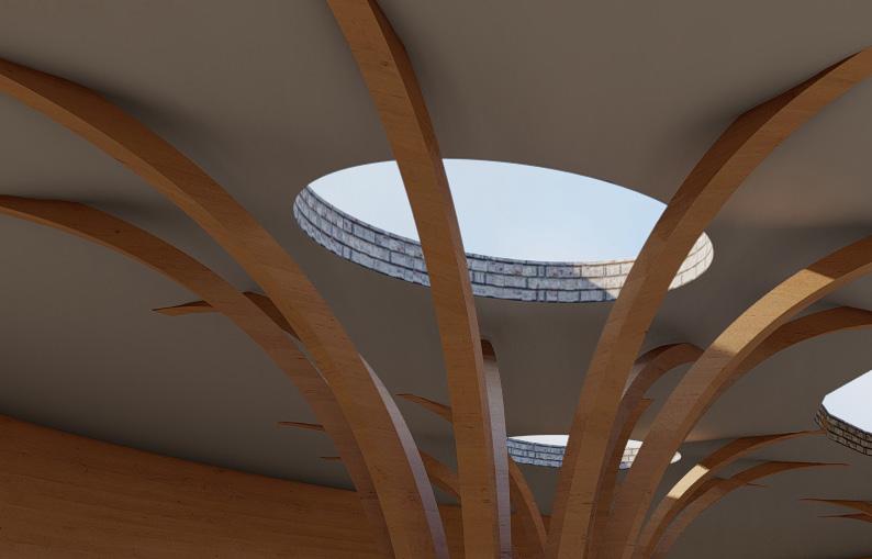
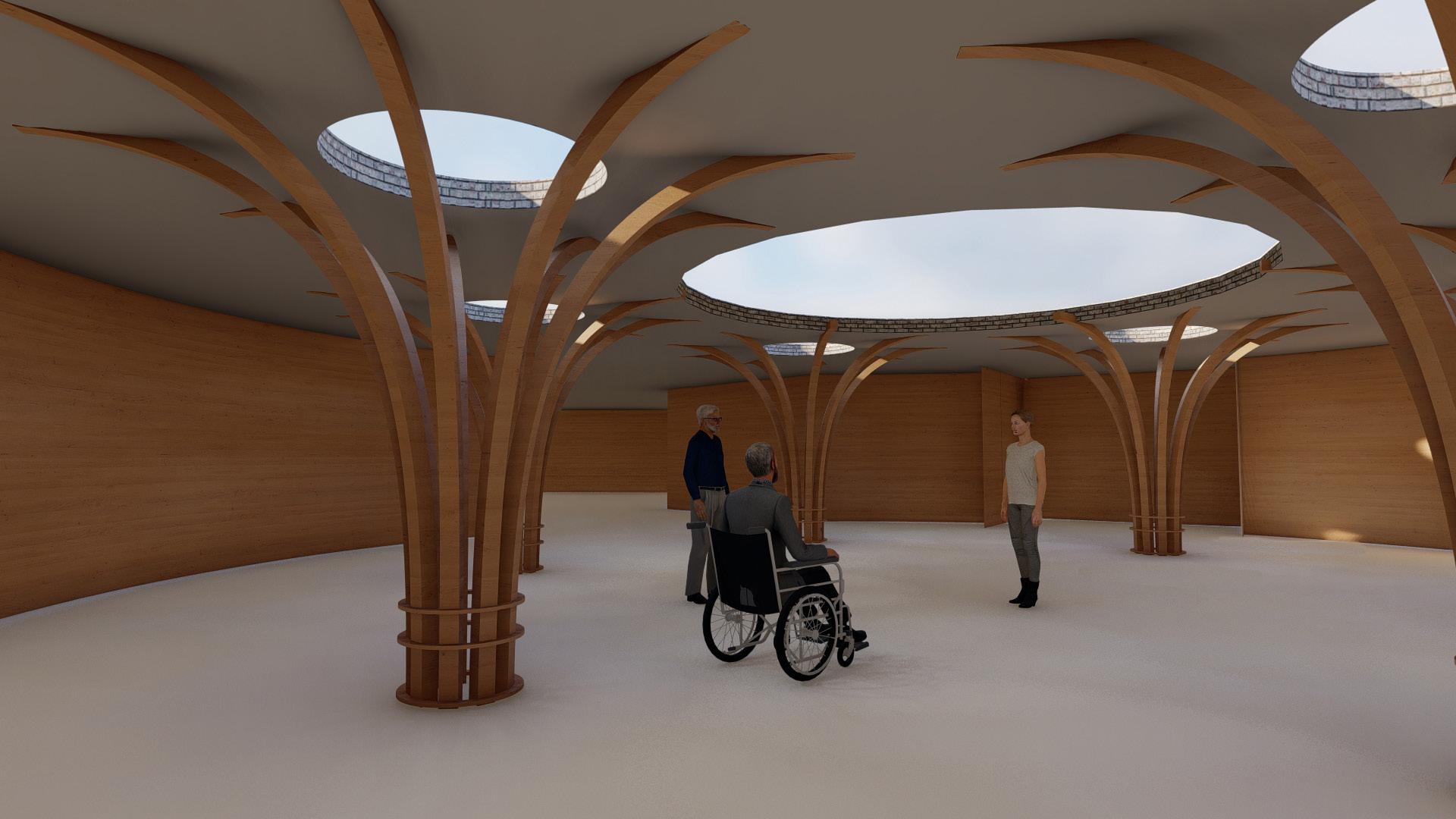
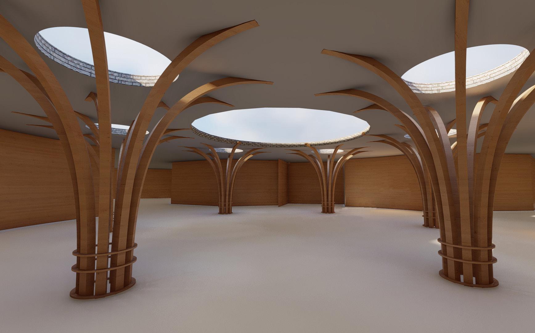
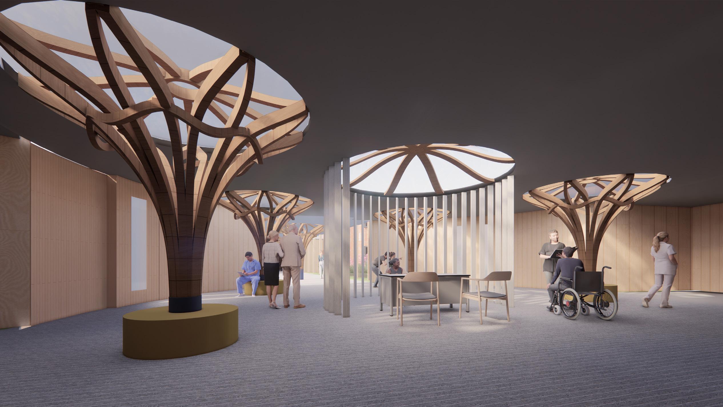
By extending the architectural language from Think Through Making, I applied the timber column language in my reception space. The shape of the column imitates the form of a tree, hence it would avoid the space from feeling cold and institution. At the top of the column, the skylight would be applied with frosted glass, which would not generate shadow on the floor.
25
26
Final reception interior images
Part 05
Critical Reflection
As a stage 3 student, there are still many areas to be understood in the design of architecture. According to this report, I found that a simple concept to a usable building is a very long and complex process. Many gorgeous ideas may cause huge energy use, or can not meet the requirements of regulations. The architectural form that truly achieves sustainability and provides a comfortable environment may cause great sacrifices in aesthetics. So this report reminds me that the design of architecture is not a beautiful sculpture, the designer should have a deep understanding of the impact of the services it provides, both on users and the environment.
In my design, I found that I did not achieve sustainable architecture perfectly, which is what I need to consider in the early stage of design in the future, rather than modify the design afterward. Similarly, I need a better understanding of the regulations to avoid modifying the proposal by making inappropriate space.
I firmly chose timber as the primary structure. Although the shape of this design is very conservative, it still helps me to have a basic understanding of construction sequence. This makes me closer to reality and realizes that architecture needs more reality-based than aesthetics.
To sum up, writing this report has taught me a lot of information. For example, ventilation, meeting building regulations, etc. Having this knowledge really allows me to improve making better design decisions in my future study or career.
Part 06
Referencing / Bibliography
Approved Documents (Part B); available at: https://www.gov.uk/government/publications/fire-safety-approved-document-b
Carballeira M, Hamza N. (2016) Assessment of Indoor Visual Environments Using Dementia-Friendly Design Criteria in Day Care Centres. In: Building Simulation and Optimization, Third IBPSA-England Conference. 2016, Newcastle upon Tyne, UK: Newcastle University.
Centre for Geriatric Psychiatry in Pffers; available at: https://inspiration-detail-de.libproxy.ncl.ac.uk/startseite.html?lang=en
Connections in cross-laminated timber; available at: https://www.fpl.fs.fed.us/documnts/pdf2013/fpl_2013_mohammad001.pdf
Corium Brick Tile Cladding;available at: https://www.taylormaxwell.co.uk/facade-systems/corium-brick-cladding
Corium Brick Tile Cladding;available at: https://www.wienerberger.co.uk/products/facades/corium-brick-cladding-systems.html
Housing and Commercial Development in Neu-Ulm; available at: https://inspiration-detail-de.libproxy.ncl.ac.uk/startseite.html?lang=en Ice database; available at: https://circularecology.com/embodied-carbon-footprint-database.html
Mass Timber Design Guide; available at: https://www.structurlam.com/wp-content/uploads/2019/04/Structurlam-Design-Guide_FINAL_Spreads.pdf
The CLT Handbook CLT structures facts and planning; available at: https://www.woodcampus.co.uk/wp-content/uploads/2019/05/Swedish-WoodvvCLT-Handbook.pdf
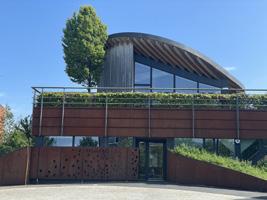
Wine Cellars in Girlan; available at: https://inspiration-detail-de.libproxy.ncl.ac.uk/startseite.html?lang=en
28
Part 07
List of Illustrations
Page 2 Author owns all images
Page 3 Author owns all images
Page 4 Author owns all images
Page 5 Author owns all images
Page 6 Author owns all images
Page 7 Author owns all images
Page 8 Author owns all images
Page 9 Author owns all images
Page 10 Author owns all images
Page 11 Author owns all images, except image 1, retrieved from google earth; image 2, retrieved from: https://www. concretenetwork.com/concrete/demolition/recycling_concrete.htm
Page 12 Author owns all images
Page 13 Author owns all images
Page 14 Author owns all images, except image 1-3, retrieved from ICE darabase; image 4-5. retrieved from : https://www. istructe.org/IStructE/media/Public/Resources/istructe-how-to-calculate-embodied-carbon.pdf
Page 15 Author owns all images
Page 16 Author owns all images
Page 17 Author owns all images
29
Page 18 Author owns all images
Page 19 Author owns all images
Page 20 Author owns all images, except image 1-3, retrieved from: approved document B
Page 21 Author owns all images
Page 22 Author owns all images, except image 2, retrieved from: approved document B
Page 23 Author owns all images
Page 24 Author owns all images
Page 25 Author owns all images
Page 26 Author owns all images
Page 27 Author owns all images
Page 28 Author owns all images
Page 29 Author owns all images
30
