
$10.00 JANUARY 2016 VOLUME 43, ISSUE 01 Canadian Publication Mail Contract – 40070050 RETURN UNDELIVERABLE CANADIAN ADDRESSES TO: CSPG – 110, 333 - 5 Avenue SW Calgary, Alberta T2P 3B6 Addressee Additional Delivery Information Street Address Postal Box Number and Station Information Municipality, Province/Territory Postal Code 15 Geomodeling: A Team Effort to Better Understand Our Reservoirs Part 7: Reservoir Engineers and Geomodeling 23 Structure Seminar and Field Trip: Tribute to Dr. Deborah Spratt 24 2015 CSPG Awards 27 2016 Board of Directors
FEBRUARY

Courses Include:
u Deepwater Reservoir Connectivity
u Fluvial Sedimentology and Geomorphology
u Applied Seismic Geomorphology and Seismic Stratigraphy
– Extracting Geologic Insights from 2D and 3D Seismic Data
u Carbonate Reservoir Geology: Understanding Depositional and Diagenetic Factors Controlling Porosity
u Carbonate Depositional Systems
u Applying Ideas of Carbonate Sedimentology, Stratigraphy and Depositional Environments to Petroleum Exploration and Production
u Extracting Geology from Seismic Wiggles: Basic Seismic Interpretation for Non-Geophysicists
u Integrating Data from Nano- to Macro-Scale: Improving Characterizations of Unconventional Plays
u Essentials of Production Geology
u Shale Gas Geomechanics
u Applications of Stable Isotope Geochemistry in the Petroleum Geosciences
u Log Analysis of Shaly Sand Reservoirs
u Log Analysis of Hydrocarbon-Bearing “Shale” Reservoirs
Hosted by:
Norris Conference Center
816 Town & Country Lane, Suite 210
Houston, TX 77024
Registration and Information
Call AAPG toll free in the U.S. and Canada at 888.338.3387 or 918.560.9430
F: 918.560.2678 • E: educate@aapg.org
Phone: 713-590-0950
Fax: 713-590-0961
W: www.aapg.org/career/training/in-person/education-conference

February 29-March 4, 2016 - Houston, Texas
13TH ANNUAL
World-Class Education Conference Upcoming Education Courses
www.aapg.org/career/training/ HOUSTON, TEXAS
29-MARCH
4, 2016 World-Class Education Conference 2016
CSPG OFFICE
#110, 333 – 5th Avenue SW
Calgary, Alberta, Canada T2P 3B6
Tel: 403-264-5610
Web: www.cspg.org
Please visit our website for all tickets sales and event/course registrations Office hours: Monday to Friday, 8:00am to 4:30pm
The CSPG Office is Closed the 1st and 3rd Friday of every month.
OFFICE CONTACTS
Membership Inquiries
Tel: 403-264-5610
Email: membership@cspg.org
Technical/Educational Events: Biljana Popovic
Tel: 403-513-1225
Email: biljana.popovic@cspg.org
Advertising Inquiries: Kristy Casebeer
Tel: 403-513-1233
Email: kristy.casebeer@cspg.org
Sponsorship Opportunities: Lis Bjeld
Tel: 403-513-1235
Email: lis.bjeld@cspg.org
Conference Inquiries: Candace Jones
Tel: 403-513-1227
Email: candace.jones@cspg.org
CSPG Foundation: Kasandra Amaro
Tel: 403-513-1234
Email: kasandra.amaro@cspg.org
Accounting Inquiries: Eric Tang
Tel: 403-513-1232
Email: eric.tang@cspg.org
Executive Director: Lis Bjeld
Tel: 403-513-1235, Email: lis.bjeld@cspg.org
EDITORS/AUTHORS
Please submit RESERVOIR articles to the CSPG office. Submission deadline is the 23rd day of the month, two months prior to issue date. (e.g., January 23 for the March issue).
To publish an article, the CSPG requires digital copies of the document. Text should be in Microsoft Word format and illustrations should be in TIFF format at 300 dpi., at final size.
CSPG COORDINATING EDITOR
Kristy Casebeer, Programs Coordinator, Canadian Society of Petroleum Geologists
Tel: 403-513-1233, kristy.casebeer@cspg.org
The RESERVOIR is published 11 times per year by the Canadian Society of Petroleum Geologists. This includes a combined issue for the months of July and August. The purpose of the RESERVOIR is to publicize the Society’s many activities and to promote the geosciences. We look for both technical and non-technical material to publish. The contents of this publication may not be reproduced either in part or in full without the consent of the publisher. Additional copies of the RESERVOIR are available at the CSPG office.
No official endorsement or sponsorship by the CSPG is implied for any advertisement, insert, or article that appears in the Reservoir unless otherwise noted. All submitted materials are reviewed by the editor. We reserve the right to edit all submissions, including letters to the Editor. Submissions must include your name, address, and membership number (if applicable).The material contained in this publication is intended for informational use only.
While reasonable care has been taken, authors and the CSPG make no guarantees that any of the equations, schematics, or devices discussed will perform as expected or that they will give the desired results. Some information contained herein may be inaccurate or may vary from standard measurements. The CSPG expressly disclaims any and all liability for the acts, omissions, or conduct of any third-party user of information contained in this publication. Under no circumstances shall the CSPG and its officers, directors, employees, and agents be liable for any injury, loss, damage, or expense arising in any manner whatsoever from the acts, omissions, or conduct of any third-party user.
Printed by McAra Printing, Calgary, Alberta.

Tusan Beach, Sarawak, Malaysia. Steeply dipping strata
COVER
FRONT
belonging the Miocene Lambir Formation, truncated by the Terrace Unconformity and capped by Pleistocene aged flat lying sands. The poorly cemented sandstones erode quickly to form caves, arches and seastacks. This interesting arch is known locally as the Horsehead. Photo by: Philip Benham - benham.philip@gmail.com. JANUARY 2016 – VOLUME 43, ISSUE 01 ARTICLES Geomodeling: A Team Effort To Better Understand Our Reservoirs Part 7: Reservoir Engineers and Geomodeling 15 Structure Seminar and Field Trip: Tribute to Dr. Deborah Spratt 23 2015 CSPG Awards .................................................................................................................... 24 2016 Board of Directors ........................................................................................................... 27 DEPARTMENTS Message from the Board 5 Technical Luncheons 8 Division Talks 11 Rock Shop ......................................................................................................................... 7, 13, 23 RESERVOIR ISSUE 01 • JANUARY 2016 3

CSPG BOARD

PRESIDENT
Greg Lynch president@cspg.org Tel: 403.384.7704

PRESIDENT ELECT
Mark Cooper presidentelect@cspg.org

PAST PRESIDENT
Tony Cadrin pastpresident@cspg.org

FINANCE DIRECTOR
Scott Leroux directorfinance@cspg.org Tel: 403.766.5862

FINANCE DIRECTOR ELECT
Shelley Leggitt directorfinanceelect@cspg.org

DIRECTOR
Mark Caplan conferences@cspg.org

DIRECTOR
Jen Russel-Houston • Osum Oil Sands Corp. Jrussel-houston@osumcorp.com Tel: 403.270.4768

DIRECTOR
Eric Street • Jupiter Resources street@jupiterresources.com Tel: 587.747.2631

DIRECTOR
John Cody industryrelations@cspg.org

DIRECTOR
Ryan Lemiski • CSPG ypg@cspg.org

EXECUTIVE DIRECTOR
Lis Bjeld • CSPG lis.bjeld@cspg.org Tel: 403.513.1235
Message from the Board
A message from 2015 President, Tony Cadrin

Happy New Year CSPG Members
As I look back on this past year I am reminded of one question I was pondering when I last wrote an article addressing the Canadian Society of Petroleum Geologists Membership; what will 2015 bring the Petroleum Sector, and the Canadian Society of Petroleum Geologists members? That answer is quite clear now, 2015 was a year of challenges for the Petroleum Industry and to our members as well.
As the year unfolded we were constantly reminded of our society’s theme of PERSPECTIVE. History tells us that petroleum sector has gone through many commodity cycles in the past, and to be certain, we are currently in the depth of one now, which is just as impactful as the one we survived in the mid-late 1980s. As a society, we have a wealth of knowledge regarding technical skills, career development, and past sector cycles. This collective knowledge of our members is our strength, and is available to all of us as we navigate this current down-cycle.
As a review, our initiatives that guided our focus and activities for 2015 were:
1. 1. Improving the GeoConvention Partnership LLP
2. 2. Building our presence across Canada by seeking synergies between Industry, Universities and Governments through the Ambassador program
3. 3. Invite and Engage Past Presidents into active roles with- in the Society
A fantastic example of collected knowledge being available to the CSPG is through our Past Presidents initiative.
I would like to acknowledge these individuals who devoted their time and skill to the CSPG. When you see these people, please thank them for their guidance and listen to their advice on how to move forward.
• Dale Leckie - Ambassador at Large, Oil Sands and Heavy Oil Symposium, Gussow 2015, International Core Conference at ACE 2016
• Paul Mckay - CSPG Chair ACE 2016, Gussow 2015
• Kirk Osadetz - CSPG Foundation Trustee
• John Varsek - Past Presidents Advisory Council
• Graham Bloy - Hunter Award Committee, Short Course Author
• Colin Yeo - Ambassador Vice Chair, Southern Ontario Ambassador, CSPG Award Task Force
• Jeff Packard – ESfS Committee Member
• Craig Lamb – Atlantic Provinces Ambassador
• John Hogg – Past President Advisory Council, AAPG President 2015-2016
• Brad Hayes - BC and Prairie Ambassador
• Ian Hutcheon - BC Ambassador
• Ed Klovan – Presidents Special Awards Committee (Bob McCrossan/ Perry Glasiter original editors of the First Atlas of the Western Canada Sedimentary Basin)
(... Continued on page 7)
RESERVOIR ISSUE 01 • JANUARY 2016 5
Submit your hike to be featured in the “GO TAKE A HIKE” SERIES
Before writing an article please contact the series coordinator via email at Philip.Benham@shell.com. He can provide a template document and confirm that a particular hike has not been submitted before.
Submission guidelines:
Preferred format is powerpoint, 2-3 pages in length, include map, hike directions, annotated photos, Geological description and references. While hikes focus on western Canada, hikes in other parts of the world are welcome.

CSPG Regional Graduate Student Scholarships
4 x $2,500 awards available by region (Atlantic/Quebec, Ontario, Western, Open)
Eligibility:
Graduate Students enrolled full-time at a Canadian University in their first year of an MSc or PhD Geology or Earth Science Program
Disciplines include: Sedimentology, structural geology, stratigraphic studies involving clastic or carbonate rocks, paleontology, geochemistry, hydrogeology, petrophysics and reservoir geology
Active student members of CSPG (membership is free!)
Previous winners are not eligible
Application deadline is January 15, 2016
For application form and other requirements please see www.cspg.org/scholarships
CORPORATE SPONSORS
SAMARIUM
CSPG Foundation
geoLOGIC systems ltd.
DIAMOND
AGAT Laboratories
TITANIUM
Tourmaline Oil Corp.
Alberta Energy Regulator
APEGA
PLATINUM
Weatherford Canada Partnership
Cenovus Energy
Loring Tarcore Labs Ltd.
SILVER
Seitel Canada Ltd.
Enerplus Corporation
Imperial Oil Resources
Nexen ULC
Chinook Consulting
MEG Energy Corp.
BRONZE
Talisman Energy
Long Run Exploration
Qatar Shell GTL Limited
Osum Oil Sands Corp.
Crescent Point Energy Trust
Exxonmobil Exploration Co. Ltd.
Pro Geo Consultants
Belloy Petroleum Consulting
IHS Global Canada Limited
Paradigm Geosciences Ltd.
CSEG Foundation
MJ Systems Core Laboratories
GLJ Petroleum Consultants Ltd.
As of November 25, 2015
A Special Thanks to Geologic Systems Ltd.,
CSPG’s Top Sponsor of the Month.
• Gordon Williams – Awards Review Task Force
• Ian McIlreath – Ambassador Chair and Prairie Ambassador, Awards review Task Force Chair, Medal of Merit, Hunter, and RJW Douglas Medal Award Committees, Mountjoy Carbonate Conference Field Trips and Core Conference Chair, Bulletin Associate Editor
• Bill Ayrton – SIFT Founder, Lecturer, and Judge
The Board of Directors committed to delivering valuable services to its membership in 2015, whatever your experience or career path. We realized our goal to maximize services to members through our many successful events, which were facilitated by our dedicated volunteers and staff. When you see these people, please thank them for their efforts on our behalf and ask them what you can do to get involved. Through joint member meetings we managed our risk and enhanced the learning experience by combining our efforts with our valued partner societies in 2015 through:
• AAPG through the Playmakers Forum , March 1
• CSEG and CWLS through GeoConvention, May 4-8th
• SEPM through Eric Mountjoy Carbonate Research Conference, August 23-28th
• U of C Geoscience faculty through Gussow Conference on FineGrained Rocks, Oct 13-15
In 2016 the CSPG will host:
• CSPG Annual General Meeting at our January 14, 2016. In addition to the technical lunch presentation, there will also be an opportunity to welcome your new executive directors.
• GeoConvention ‘Optimizing Resources’ March 7th to 11th
• Long Time Members Reception May 5th
• CSPG Host Society - ACE June 19th to 22nd
• CSPG Host Special Invitation Reception June 21st
• CSPG International Core Conference June 23rd and 24th
In conclusion, the CSPG and its members have proven their resilience by working together to host and attend the many events that contribute to our career development and prepare us for the inevitable recovery of our petroleum industry.
Thank you, for a year of many fond memories, and for the opportunity to serve the CSPG membership.
Sincerely,
Tony Cadrin
(... Continued from page 5) Independent Wellsite Consultants Highly Skilled Competent Consultants Extensive Industry Experience (18 yrs +) Wellsite & Remote Supervision & Geosteering All Types of Conventional & Unconventional Wells Core, Chip Samples & Thin Section Studies International & Domestic Email: indwellcons5@gmail.com Tel: (403) 540-8496 Rock Shop
TECHNICAL LUNCHEONS JANUARY LUNCHEON
Back for more?
The first Permian oil discovery in the Barents Sea has many analogues in the Sverdrup Basin, Arctic Canada
SPEAKER
Benoit Beauchamp
Department of Geoscience, University of Calgary, Calgary, Alberta
11:30 am
Thursday, January 14, 2016
Calgary, TELUS Convention Centre Calgary, Alberta
Please Note Price Changes
Please note: The cut-off date for ticket sales is 1:00 pm, five business days before event [Thursday, January 07, 2016].
CSPG Member Ticket price: $ 39.75 +GST
Non-Member Ticket price: $ 47.50 +GST
Each CSPG Technical Luncheon is 1 APEGA PDH credit. Tickets may be purchased online at https://www.cspg.org
ABSTRACT
The 2013 Gohta oil discovery is the first
significant discovery in the Permian succession of the Barents Sea. The oil pool lies beneath a sub-Early Triassic angular unconformity, suggesting block faulting and tilting prior to the onset of Triassic sedimentation. The reservoir rocks are Permian spiculitic cherts and heterozoan carbonates of shallow origin that accumulated at a time of cool oceanographic conditions. The porosity may be the result of extensive sub-Triassic subaerial karsting. The seemingly unique set of attributes of the the Gohta Discovery has been observed at a number of localities in the Canadian Arctic Archipelago. The Sverdrup Basin was adjacent to the Barents Sea area throughout its Late Paleozoic-Mesozoic history prior to the break-up of Pangea. The succession is thicker than that of the Barents Sea, owing to greater subsidence rates, but its stratigraphic sequences are identical. Permian spiculitic chert is widespread, especially in the Late Permian succession, when carbonates were all but eradicated.The loss of carbonates can be in part associated with cooler oceanic conditions and possibly to upwelling-enhanced ocean acidification along NW Pangea. Late Permian organic-rich shales locally interfinger with the chert and may constitute a source rock. Porosity is unusually high in Late Permian chert. Large carbon isotopic depletion in carbonate material beneath the sub-Triassic unconformity suggests extensive meteoric leaching occurred. The sub-Triassic unconformity is widespread and one of the basin’s most significant in terms of base level drops.The unconformity is also locally angular
and associated with basal conglomerates of Permian pebble to cobble spiculitic chert clasts. An angular relationship is observed on northern Ellesmere and Axel Heiberg islands. From these observations we conclude the set of conditions that led to Gohta is a genuine play worth exploring some more in the Barents Sea and, when conditions are right, in the Sverdrup Basin as well.
BIOGRAPHY
Benoit is a Professor of Geoscience at the University of Calgary. He obtained his undergraduate and M.Sc. degrees in geology at the Université de Montréal studying Carboniferous carbonates from Western Canada. Subsequently, he moved to Calgary to pursue a Ph.D. in geology at the University of Calgary. For his dissertation, he studied Carboniferous and Permian sedimentary rocks in the Canadian Arctic. After obtaining his Ph.D. in 1987, Benoit worked for 18 years as a Research Scientist with the Geological Survey of Canada in Calgary, leading major field expeditions to the High Arctic. In 2005, he became the Executive Director of the Arctic Institute of North America at UofC. In 2011, he returned to the Department of Geoscience as a full-time professor. Much of Benoit’s research interests revolve around understanding the Late Paleozoic-Early Triassic sequences and petroleum systems, which takes him to exotic places such as Ellesmere Island, Svalbard and Oman. Benoit has been an active contributor to many CSPG events and endeavours over the years, including his leadership roles in the 1993 and 1997 CSPG Conventions and in the 2007 Gussow Conference.
8 RESERVOIR ISSUE 01 • JANUARY 2016
Webcasts sponsored by
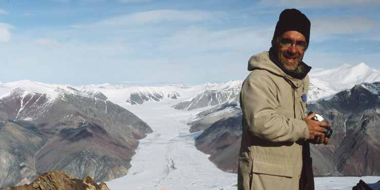
Antarctica’s sedimentary archives of past glacial history: Tools for understanding climate change
SPEAKER
Julia Wellner
AAPG Distinguished Lecturer
11:45 am
PLEASE NOTE DATE, TIME, PRICE CHANGES
Wednesday, January 27, 2016
Calgary, TELUS Convention Centre
Calgary, Alberta
Please note: The cut-off date for ticket sales is 1:00 pm, five business days before event [January 20, 2016].
CSPG Member Ticket price: $ 39.75 +GST
Non-Member Ticket price: $ 47.50 +GST
Each CSPG Technical Luncheon is 1 APEGA PDH credit. Tickets may be purchased online at https://www.cspg.org
ABSTRACT
During times of past extensive glaciations, the Antarctic ice sheet extended from its current position, reaching across the continental shelf. As the ice sheet retreated to its modern extent, the shrinking ice sheet left behind seawater, rather than ancient ice, leaving behind a sedimentary signature of deglacial history. Marine geophysical survey data, including 3.5 kHz profiles and multibeam swath bathymetry, combined with sediment cores, are used to map the extent of past ice, estimate the speed at which it was flowing, and understand the style of retreat. Radiometric dating gives ages of retreat and allows comparison to other global archives. Past periods of glacial retreat, which tend to be diachronous, are compared to the modern day retreat, which is happening across large areas in a short period of time. Ongoing work is targeting records from times of past high CO2 conditions, like those predicted in


our future.
BIOGRAPHY
Julia Wellner - Wellner is a sedimentologist and stratigrapher who works primarily in the Gulf of Mexico and offshore Antarctica on questions related to sediment facies, stratigraphic architecture, glacial history, and sea-level change. She earned her PhD from Rice University in 2001 where she also completed a post-doctoral fellowship. She has been at the University of Houston since 2006 where she teaches stratigraphy, sequence stratigraphy, marine geology, and oceanography. Wellner has completed over a dozen ocean-going cruises collecting seismic data and sediment cores, including eight in Antarctica.
www.geoconvention.com GeoConvention 2016 With low commodity prices and an everchanging economic and business environment, it is imperative that the industry optimize the way in which it operates. Whether enhancing recovery methods, finding the optimal path for a horizontal well
maximizing the return of capital employed,
Resources, the theme for GeoConvention 2016, is key to success. Please join us and contribute
speaker, exhibitor
sponsor In recognizing the business environment which we are operating in, GeoConvention is pleased to offer heavily discounted delegate rates for the 2016 program. New for our 2016 program, in addition to the technical program and exhibit floor at the Convention Centre, we will be hosting an offsite component, including panel discussions, workshops and a mini core conference at the Lake Louise Inn – check out www.geoconvention.com for details. REGISTRATION NOW OPEN MARK YOUR CALENDAR GeoConvention 2016 is March 7 – 11 RESERVOIR ISSUE 01 • JANUARY 2016 9 TECHNICAL LUNCHEONS JANUARY LUNCHEON Webcasts sponsored by
or
Optimizing
as
or
TECHNICAL LUNCHEONS FEBRUARY LUNCHEON
SPE-CSPG Joint Luncheon: Advances in Multivariate Property Modeling and Applications to Uncertainty in Reservoir Forecasting
SPEAKER
Dr. Clayton Deutsch
University of Alberta, the School of Mining & Petroleum Engineering
11:30 am
Tuesday, February 09, 2016
Calgary Petroleum Club, Devonian Room Calgary, Alberta
Please note:
The cut-off date for ticket sales is 4:00 pm, Friday, February 5th, 2016
CSPG Member Ticket Price: $45.00 + GST.
Tickets may be purchased online at https://specalgary.com

ABSTRACT
Geostatistical reservoir modeling has advanced in recent years. Some of the most notable advances have been in multivariate modeling, for example, simultaneous
numerical modeling of the volume fraction of shale, total porosity, effective porosity, horizontal permeability, vertical permeability, residual water saturation and so on. Characterizing the uncertainty of these variables is relatively straightforward with the latest techniques. Complex relationships such as that shown to the below can be accommodated. Techniques will be reviewed.
There have also been significant advances in the use of multiple realizations in reservoir forecasting. The paradigm of a single best or P50 model is being eroded and replaced with the more correct paradigm of managing multiple realizations simultaneously. Example applications will be shown.
BIOGRAPHY
Dr. Deutsch is a Professor in the School of Mining and Petroleum Engineering at the University of Alberta. He received PhD and MSc degrees in Geostatistics from Stanford. He leads the Centre for Computational Geostatistics (CCG) where he teaches
and conducts research into better ways to model heterogeneity and uncertainty in petroleum reservoirs and mineral deposits. Dr. Deutsch has published eight books and over 300 research papers. Dr. Deutsch holds the Alberta Chamber of Resources Industry Chair in Mining Engineering and the Canada Research Chair in Natural Resources Uncertainty Characterization.

10 RESERVOIR ISSUE 01 • JANUARY 2016
DIVISION TALKS INTERNATIONAL DIVISION
From the Gobi Desert to Genghis Khan:
Exploring for Heavy Oil
in Mongolia
SPEAKER
Jürgen Kraus
Franconia Geoscience Ltd., Calgary
12:00 Noon
Wednesday, January 13th, 2016
Nexen Annex Theatre
ABSTRACT
Mongolia is possibly one of the earth’s most remote and cryptic places for hydrocarbon exploration. Following its early prime under Genghis Khan to his grandson Kublai Khan (12th and 13th centuries), the country was isolated from western civilization until recently. In 1924, Mongolia fell under Soviet control. The country transitioned to a market economy only in 1990 and the last Russian troops left in 1992.
Mongolia hosts 10% of the world’s known coal reserves and has a long tradition in open-pit mining. Oil was found in 1940 in the Gobi region and the first PSC was signed in
1993. The Petroleum Authority of Mongolia (PAM) was established in 1990 as the stateowned petroleum agency. Today, there are 30 exploration blocks, and two basins produce: Tamsag and East Gobi.
This is a brief account of frontier exploration in the deformed and inverted lacustrine Nyalga rift basin. The general plate-tectonic setting will be introduced, from the amalgamation of island arcs in the Late Permian through northward subduction underneath Siberia, the complications of which resulted in rift-related subsidence and the development of lacustrine basins in the Late Jurassic/Early Cretaceous. The geometry and structural/sedimentary evolution of Nyalga will be discussed, from the rifting to Late Cretaceous inversion, and put into context with the working petroleum systems.
Join in on a journey heading south from the capital Ulaanbaatar through the steppe and dry steppe into the Gobi desert to investigate the East Gobi basin near the Chinese border, considered to be a Nyalga analog. The “road” you are following is the Transmongolian Railway and your GPS map is almost featureless but for the single point that translates to “Good Spring”. You will stay in a traditional yurt, where they serve you a hearty beef stew for breakfast and a marmot with fermented mare’s milk for dinner. In the absence of trees (i.e. firewood), “bullshit” will get a comfortable new meaning for you on
Sponsored by
cold nights. You will meet nomads in the vast grasslands of the Nyalga basin herding camels and visit an abandoned Soviet airbase.
The two Nyalga reports submitted to PAM can be downloaded from franconia-geo.com. The website also contains a few field video clips.
Refreshments and door prizes will be provided. Please bring a colleague!
BIOGRAPHY
Jürgen is a consulting geologist in international hydrocarbon exploration specializing in prospect generation in deformed and fractured frontier basins. Since establishing “Franconia Geoscience Ltd.” in 2003, he has helped establish the technical foundations to build small companies on and has worked on international exploration projects in countries such as China, Mongolia, Morocco, and Germany. Previously, he had performed structural modelling and seismic interpretation in the Foothills for Shell Canada. He has 27 years of field experience.
Jürgen holds an M.Sc. in Structural Geology and Geophysics from Göttingen University, Germany (1991), and a Ph.D. in Structural Geology and Tectonics from the University of New Brunswick (1998). Before moving to Calgary, he had assignments with GSC Ottawa, Aachen University of Technology, and the Saskatchewan Geological Survey.

RESERVOIR ISSUE 01 • JANUARY 2016 11
Jürgen Kraus, Franconia Geoscience Ltd., Calgary
DIVISION TALKS STRUCTURAL DIVISION
Natural Fracture Networks of the Turonian Second White Specks Formation, Highwood River, Southwestern
Alberta
SPEAKER
Bram Komaromi and
Dr. Per K. Pedersen
Department of Geoscience, University of Calgary
12:00 noon
Thursday, January 14th 2016
Schlumberger, Second Floor of the Palliser One Building, 125 9th Ave. Calgary T2G 0P6
ABSTRACT
Detailed analysis of natural fracture network geometry is an important step in the geomechanical modelling and characterization of unconventional tight reservoirs as fractures provide flow pathways for hydrocarbons in the subsurface as well as influence hydraulically induced fracture development. Characterization of subsurface fractures is challenging since boreholes provide a limited view, but outcrops provide useful 3D subsurface
analogs. Outcrops of the Second White Specks Formation along the Highwood River in southwestern Alberta were divided into three major facies: 1) the Jumping Pound Sandstone; 2) interbedded finely laminated siltstones and mudstones; and 3) black organic-rich mudstone. Fracture parameters were recorded using the scanline sampling method from each facies at two outcrops located in different structural positions within the thrust belt. Results were used to examine the differences in natural fracture characteristics between sedimentary facies in the Second White Specks Formation. The Jumping Pound Sandstone contains compressional conjugate shear fractures that occur at intensities of 4.2–7.4 fractures per meter with average heights of 0.60–0.79 meters. The interbedded finely laminated siltstones and mudstones contain extensional fractures that occur at much higher intensities of 29–33 fractures per meter with much shorter average heights of 0.06–0.18 meters, the latter being related to the finely interlaminated siltstonemudstone fabric. The black organic-rich mudstone also contains extensional fractures but has fracture intensities comparable to those of the Jumping Pound Sandstone at 4.2–4.9 fractures per meter with average heights of 0.50–1.25 meters. Elevated fluid pressures resulting from oil generation from Type II kerogen within the two mudstone facies could have increased pore pressure to the point that promoted the formation of extensional fractures compared to the shear fractures that occur in the overlying Jumping Pound Sandstone. The results from this study
Sponsored by
suggest the anisotropy and heterogeneity of sedimentary facies characteristics such as lithology, organic content and type, sedimentary fabric and mechanical bed thickness have strong influences on natural fracture characteristics in the Second White Specks Formation outcrops along the Highwood River. These observed relationships give valuable insight into the influence of sedimentary facies on natural fracture networks in unconventional type reservoir targets.
BIOGRAPHY
Bram Komaromi is a M.Sc. candidate in the department of Geoscience at the University of Calgary. His research is focused on understanding the role and influence that sedimentary facies characteristics have on natural fracture networks in unconventional type reservoirs such as the Second White Specks Formation. Originally from Yukon, Bram began his undergraduate degree at the University of Victoria in 2009. In 2012, he transferred to the University of Calgary, and in 2014, graduated with First Class Honours in Geology. During the final year of his undergraduate, Bram completed an undergraduate thesis under the supervision of Dr. Per K. Pedersen which inspired him to continue his research as an M.Sc. candidate. Bram was a member of the 2015 University of Calgary IBA team, which placed second in the Canada Region Competition, and is also a member of the executive committee of the University of Calgary AAPG student chapter.
Many CSPG memberships expire December 31st. Watch your email for a link to renew online. **membership is on an individual basis; you may have a different expiry date** 12 RESERVOIR ISSUE 01 • JANUARY 2016
DIVISION TALKS PALAEONTOLOGY DIVISION
Sue (the Tyrannosaurus Rex) and the Chicago Field Museum
SPE A KER
Mona Marsovsky
APS Executive Member and Professional Engineer
7:30pm
Friday, January 15, 2016
Mount Royal University, Room B108
ABSTRACT
In the 1990’s controversy erupted around the Tyrannosaurus Rex (T-Rex) dinosaur named Sue. This included seizure of Sue’s
skeleton by the FBI (Federal Bureau of Investigation), court hearings which resulted in a jail sentence for the person who excavated Sue’s skeleton, and an auction in which Sue sold for more than 8 million dollars to the Field Museum in Chicago with the bill footed by the Ronald McDonald House and Disney. After years of preparation by staff and volunteers at the Field Museum in Chicago, Sue is now proudly displayed at the Field Museum. Mona will present an overview of Sue’s background and some of the things that Sue has taught us (scientific and otherwise). Mona will also illustrate some of the other treasures in the Chicago Field Museum.
BIOGRAPHY
Mona Marsovsky is a life member of the APS who has served as the APS treasurer since 2002. She is also a member of the Society of Vertebrate Paleontology. She is an amateur
DIVISION TALKS HYDROGEOLOGY DIVISION
Getting a GRIP on groundwater recharge in the prairies: How much water is available?
SPE A KER
Masaki Hayashi
Department of Geoscience, University of Calgary, Canada
12:00 noon
Wednesday January 20, 2016
IHS Office- Sunlife Plaza, East Tower 6th Floor, 112 4 ave SW Calgary, AB T2P 0H3
ABSTRACT
Groundwater is a renewable resource, and its extraction rates need to be managed to ensure that the resource is available for future generations and extractions do not cause negative environmental impacts. The permissible rate of extraction, often called “safe yield”, has been commonly evaluated for individual wells without considering its connection with the hydrologic cycle and the environment. This has resulted in many cases of depletion of aquifers and reduction
of the stream flow provided by groundwater. A new paradigm is emerging, which considers the balance between rates of groundwater extraction and replenishment (i.e. recharge) in the context of the hydrologic cycle as the foundation of sustainable groundwater management. Estimation of groundwater recharge in the prairies represents a major challenge due to the unique combination of cold climate influenced by snow and frozen soil, undulating topography shaped by the last glaciations, and thick sequence of clay-
Rock Shop
Sponsored by
whose paleo habit has been supported by her work as a professional engineer (Mona Trick P. Eng.) programming gas and oil field optimization software for the oil industry. As part of her work, she has taught training courses and given luncheon talks all over the world.
INFORMATION
This event is presented jointly by the Alberta Palaeontological Society, the Department of Earth and Environmental Sciences at Mount Royal University, and the Palaeontology Division of the Canadian Society of Petroleum Geologists. For details or to present a talk in the future, please contact CSPG Palaeontology
Division Chair Jon Noad at jonnoad@hotmail. com or APS Coordinator Harold Whittaker at 403-286-0349 or contact programs1@ albertapaleo.org. Visit the APS website for confirmation of event times and upcoming speakers: http://www.albertapaleo.org/.
Sponsored by
rich sediments resulting in highly variable recharge fluxes in both space and time. I will present the hydrogeological principles for understanding recharge processes and the results of the Groundwater Recharge in the Prairies (GRIP) project, demonstrating the decadal-scale variability of groundwater recharge in prairie watersheds in Alberta.
For more information about CSPG Division talks please go to www.cspg.org

DIVISION TALKS GEOMODELING DIVISION
The truth about SAGD start-up: Reservoir effects on SAGD circulation operations through wellborereservoir numerical modelling
SPEAKER
Jose Romero
Schlumberger
12:00 noon
Tuesday Jan 26th, 2016
Husky Conference Room A, 3rd Floor, +30 level, South Tower 707 8th Ave SW, Calgary, Alberta
ABSTRACT
Currently the Canadian SAGD industry considers the start-up circulation heating process the most fundamental part of the SAGD; it builds the initial connectivity between the well pair to make the wells flow and produce efficiently. More than 70% of the SAGD projects in Canada have failed due to a poor circulation design that has directly affected the SAGD performance in terms of Steam-to-Oil Ratio and recovery factor. Experience has shown that startup is a complex process requiring a good understanding of the reservoir characteristics and subsequent implementation of the correct operating strategies that will create the communication between the wells of the pair.
Operating parameters such as circulation time and steam injection rate along with geological variables of water saturation and permeability were analysed to determine the best operational strategy to start the SAGD well pair.
This investigation reveals the physics and operational challenges that take place during the start-up circulation. Fully coupled wellbore-reservoir numerical modelling was used to determine the optimal operations of the start-up process before moving to the SAGD stage. The circulation stage is traditionally considered a heat conduction dominated process. The operating conditions
like: steam circulation rate and circulation time, affect directly the temperature profile along the well and the level of connectivity between the wells. However, through the implementation of different SAGD projects it has been found that convection can also influence the start-up process with high water saturation and permeability zones creating preferential connection paths between the wells, resulting in a more complex process to understand and predict.
BIOGRAPHY
Mr. Jose Romero is a Petroleum Engineer graduated from Universidad de Oriente
Sponsored by
in Venezuela, he started his career in Schlumberger in 2007 as Reservoir Engineer and Researcher in the Schlumberger Heavy Oil Technology Center. During that time he worked in multiple projects, from newtechnology development to integrated reservoir studies. In 2010 Mr. Romero worked as Reservoir Engineer Lead in different reservoir studies in the area of EOR applied to heavy oil. In 2012 he joined Schlumberger Calgary team to start working as Reservoir Engineering Consultant looking after reservoir simulation software applicability in Thermal and Unconventional reservoirs.
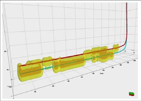
 High Water Saturation Case: Temperature profile after circulation for high initial water saturation case
14 RESERVOIR ISSUE 01 • JANUARY 2016
Base Case Model: Well pair showing temperature surface profiles along the wells.
GEOMODELING: A TEAM EFFORT TO BETTER UNDERSTAND OUR RESERVOIRS Part 7: Reservoir Engineers and Geomodeling
By Thomas Jerome, RPS, Samaneh Razzaghi, Encana Corporation and Martin Malek, Tamarack Valley Energy Ltd.
INTRODUCTION
After having discussed how geoscientists and geomodelers can efficiently collaborate, this series is now reviewing the point engineers can take in geomodeling projects. This paper focuses on the collaboration between reservoir engineers and geomodelers around the topic of flow simulation. The next two papers will look at geomodeling for reserve estimates and for production engineering respectively.
Many geomodels are built at the request of reservoir engineers. They are in need of a 3D grid, capturing the characteristics of the rocks (porosity, SW, permeability) to feed to their flow simulation software. In fact, this is largely what motivated the development of geomodeling in the first place and several decades ago. Geomodeling can be seen as a bridge between geoscientists and engineers (Figure 1). This places geomodeling at the intersection of two worlds which have always had difficulties communicating one with the other. The first part of this paper describes the common communication issues around geomodels. When not handled properly, these issues can be the cause of failure of our projects.
focuses on the technical processes involved (creation of the flow simulation grid as well as upscaling and downscaling of properties).
Transferring the uncertainties from the geomodel study into the flow simulation study is a major challenge. Which geomodels shall we use in flow simulation when potentially hundreds of 3D petrophysical distributions have been created by geostatistical algorithms? Historically, only one was used. Nowadays, several 3D geomodels are sent to flow simulation. In either case, it is up to the geomodeler to help his team to choose which 3D distributions should be used. It requires ranking the geomodels based on criteria relevant to flow simulation.This topic is covered in the last part of this paper.
COMMUNICATION, COMMUNICATION, COMMUNICATION…
What asset team doesn’t joke about geoscientists not understanding what engineers need and/or about engineers not getting what geoscientists do? These jokes are as much a way to exorcise any possible communication issue to come as they are a way to vent out the frustration of on-going problems caused by miscommunication. And

A good 3D geological grid captures all the geological, petrophysical and geophysical information gathered by geoscientists about the reservoir. The geomodeler then transfers the information stores in the geological grid into a new 3D grid fit for the purpose of flow simulation. This new 3D grid is called a flow simulation grid hereafter. The reason why a specific grid is needed is also covered in the first part of this paper. The second part
beyond that, these jokes are simply funny! Our teams are under a lot of pressure. A good joke is always a nice way to lift some of the tension we face and we should enjoy them for that!
Every geomodeler should be vigilant about this potential problem though. Too many geomodeling projects don’t reach their full potential, because of miscommunication
between geoscientists and engineers. It’s unfortunate, but luckily it can be largely avoided.The remainder of this paper provides some ways to do so.
Nothing gives a reason for a good laugh (or a fair amount of frustration) more than a geomodeling project already in progress for a few weeks (months…) and everything has to be redone because the team suddenly realizes that the model doesn’t take into account a few wells needed later for flow simulation. The question is not who shall have given the information to start with – the team, the geomodeler, the geoscientists or the engineers.The point is that it is a problem that a proactive geomodeler can easily fix, at the beginning of a project, by agreeing on the list of wells to be used.
Firstly, we must validate the list of wells with our geoscientists. On their side, it will be linked to which wells have geological/ petrophysical/geophysical data that must be taken into account in the model. Secondly, we must crosscheck this initial list with the list of wells the engineers are looking at. Many wells will be on both lists. But engineers will also consider wells with some production history, even if these wells have no data useful for modeling the geology of the reservoir. Horizontal wells tend to fall in this category. They have some production attached to them, or they will in the future and so they must be taken into account for predicting future production. Yet, they might have no data usable for geomodeling per se.Too often geomodelers forget to make sure that these wells fall in the correct geological units. That is, wells known to have been drilled in a sand layer might end up crossing into some shale units located above or below the targeted sand. It happens when the geomodeler interpolated the horizons incorrectly between vertical wells, not realizing that it placed the horizontal wells in the wrong place. Geomodeling packages have options in their workflows to take into account the complete geometry of the horizontal wells. At the same time, it is wise to check with the engineers what the lateral and the vertical extent of the volume of rock they need modeled is. Figure 3 in the second paper of this series (Jerome et al, 2015a) and its
|
(...
Continued on page 16)
RESERVOIR ISSUE 01 • JANUARY 2016 15
Figure 1. Reservoir modeling: at the intersection of geosciences and engineering.
associated paragraphs give an example of such problems.
Once the well list and the volume to model is approved by the whole team, the project can start. During the project, the geomodeler will communicate about his processes and his results to the geoscientists. Among other things, he will explain why he picked some specific geostatistical workflows and he will show that his model is indeed respecting the ideas the geoscientists have about the reservoir. It is wise to include engineers in these discussions. Firstly, it will give them more confidence in the project. Secondly, it will emulate discussions about the model inside the whole team. Geoscientists tend to focus their review on how the geomodel respects their ideas about 3D facies distribution. This is crucial, of course, but it can sometimes overshadow some mistakes a geomodel might have in term of respecting the laws of physics in general and the laws of flow dynamics in particular. Engineers will often spot such mistakes. During the presentation of his model to his team, the geomodeler should go as far as stating that he needs the geoscientists’ feedback on the facies and the porosity as well as the engineers’ feedback on the water saturation and the permeability models. In so doing, everyone knows what your expectations are for her/him.
Figure 2 gives an example of a project in which the engineer’s feedback on water saturation was crucial. It is based on an anecdote that happened to one of the authors a few years ago. The reservoir was a simple sandy geological unit. There was no facies modeling per se as the whole unit was considered made of sand. The porosity modeling didn’t cause any issue either. Water saturation proved more challenging (Figure 2A). The water saturation log showed low values everywhere with the exception of a zone close to the top of the unit, and only in the South-West corner of the reservoir. There, the water saturation was getting close to 100%. Due to a large number of input wells, this information was overlooked by the geomodeler. Water saturation was modeled using geostatistical techniques, in the same way it had been done on many other projects before. The 3D water saturation model was showing, locally, a zone of high values around the wells. Everything was consistent as far as geostatistics was concerned; the hard data were respected as well as the global saturation distribution and the global variogram. The geoscientists and the geomodeler reviewed the project. Satisfied by their model, they gave it to their engineers and they moved on to other tasks. Months later, the geomodeler
and the geoscientists discovered that the engineers were struggling with the geomodel; water was literally “raining” in their model from the zone of high saturation. To them it was, in fact, impossible that such a zone of water saturation existed there. It did not make any sense in terms of flow dynamics. Gravity would have made this water drop to the bottom of the reservoir (water being denser than the oil in this reservoir). They decided to manually edit the saturation in the problematic area to get some good flow simulation results. Naturally, they were frustrated by this situation. Reviewing the geomodel and the input data, the geoscientists discovered the source of the problem - the water saturation logs were valid, but not the facies description. It had been missed that the reservoir was showing a local continuous shale in that zone. The water saturation model was correct, but the permeability model was not. High permeability values, believed to be in a pure sand unit,had been distributed in the whole sand. Instead, it should have been set to zero in the shale unit. In that case, the water would not have “rained” in the sand below. The geomodel was rebuilt. A zone of shale was added to the facies model. The water saturation was now modeled by facies – very low in the whole sand and close to 100% everywhere in the shale. At last, permeability was computed by facies as well - high in the sand, null in the shale.
This anecdote illustrates several important points. Firstly, the engineers might indeed spot issues with fluids and permeability models that geoscientists and the geomodeler himself might miss. Secondly, if the engineers are not involved in the review and they just received the geomodel as a package thrown over a fence, there is a greater chance that they will try to correct such problems themselves rather than reporting them to the team. The team might then end up with two geomodels; the original, and the one edited behind closed doors by the engineers. And who is to blame for such situations –the engineers for not communicating about what they saw or the geoscientists and the geomodeler for not properly involving them in the review process? To avoid having to argue about such questions at a later stage, we believe it is in any geomodeler’s own interests to include engineers in their project at the same level than geoscientists are.
Involving engineers in their projects will also help the geomodelers to address two of their most common questions. Many engineers wonder why we are spending so much time building a facies model while they need only porosity, water saturation and permeability. Many also wonder why the 3D geological
grid we work on has a complex mesh and millions of cells while they specifically asked for a “sugar box”, simple 3D grid.

Flow simulation engineers need 3D grids which are aligned with the main direction of flows in the reservoir. In a simple, layercake reservoir with no fault and no folding, it means that the K axis of the 3D-grid should be indeed perfectly vertical. The horizontal mesh will be, for example, parallel and perpendicular to the horizontal wells around which the flow simulation is run. If the reservoir is fractured, the horizontal mesh will likely be built parallel and perpendicular to the main direction of the fractures. As a last example, if the reservoir is faulted, the horizontal mesh will likely be built parallel and perpendicular to the fault surfaces. In addition to this, the mesh of the flow simulation grid should be made of cells of constant size, with no truncated or eroded cells. These constraints ensure that the computations in the simulation software run faster and are more stable numerically.
The geological 3D grids are built to populate petrophysical properties in 3D. As these properties are primarily controlled by the facies distribution, we have to model facies in detail as well. Geostatistics are our main toolbox to do this. In (Jerome et al, 2015b), we explained that the orientation of the mesh of the geological 3D grid is the primary control on how the facies (and the petrophysics) are interpolated around the wells. Use a mesh that doesn’t reflect the directions of sedimentations and you are likely to get an incorrect 3D facies distribution.
In fact, building a geological 3D grid and building a flow simulation 3D grid follows the same problem. In both cases, we need a 3D grid that is aligned with the main directions of the physical phenomena we are modeling. In flow simulation, it means solving the
(... Continued from page 15)
16 RESERVOIR ISSUE 01 • JANUARY 2016
Figure 2. A) Initial, incorrect SW 3D model. B) Reinterpreted reservoir following engineer’s feedbacks.
equations of flow dynamics and the mesh must follow the directions of flow. In geomodeling, it means mimicking with geostatistics the results of physical phenomena like erosion and sedimentation and we need a 3D grid with a mesh parallel and perpendicular with the directions of deposition.Those directions are usually different from the directions of flow simulation. That’s why we can’t use the flow simulation grid to model facies, and in reverse that’s why it is unwise to run flow simulation in a 3D grid fit for facies modeling. We need two 3D grids with specific cell size, with specific orientations for the mesh and with or without eroded cells. We need a geological 3D grid and a flow simulation 3D grid. It implies that we will have to transfer rock properties from the geological grid to the flow simulation grid (it will be covered in the next part).
Explaining the need for a specific geological grid by building an analogy with flow simulation constraints have proven efficient to the authors on several occasions.
Figure 3 and Figure 4 illustrate these points. Let’s assume we have three vertical wells, each showing a succession of shale and sand. An engineer might convince a geomodeler to use a “sugar-box” 3D grid for modeling facies – that is a grid with constant cell size and horizontal and vertical mesh. The type of mesh flow simulation would be run into. If we do this, the facies model would look like a succession of horizontal sand and shale layers (Figure 3A). Let’s assume that dipmeter data shows that the sands and the shales are in fact dipping. It makes sense to build a 3D geological grid with an inclined mesh (Figure 3B). The new 3D facies model is now very different from the original one. This second approach is better than the first one as it not only respects the facies at the wells, but also the information of the dipmeter data and, from there, the geological concept developed for the reservoir– the facies are dipping. Figure 4 shows how the water saturation model would look like. This is the type of property (with porosity and permeability) that reservoir engineers need. Shall we give them our geological, inclined 3D grid for their flow simulation? Maybe, if our engineers confirm such a 3D grid is good for their work; but very likely, they will ask for the 3D petrophysical models to be transferred into a sugar box grid.
Without proper understanding, by the geomodeler, of what is needed for facies modeling and later for flow simulation, either the facies model would be wrong (Figure 3A) or the 3D-grid sent to the engineers could potentially be inadequate for flow simulation (Figure 4).


FROM 3D GEOLOGICAL GRIDS TO 3D FLOW SIMULATION GRIDS
Transferring information from the 3D geological grid into the 3D flow simulation grid is a two-step process. Firstly, the simulation grid is created. Secondly, the properties modeled in the geological grid are transferred into the flow simulation grid.
A flow simulation grid might be as simple as an upscaled version of the geological grid; the same dimension and same mesh orientation, but larger cells. For example, a geological grid of 25m*25m (Figure 5A) is upscaled to a flow simulation grid of cell size 50m*50m (Figure 5B, green mesh is the mesh of the flow simulation grid). In many projects, the flow simulation grid has larger cells than the geological grid. It’s a way to limit the total number of cells, and so to limit the computation time. Because of this, engineers might ask why we build the geological 3D grid at a smaller scale if, ultimately, the grid will be upscaled to larger cells. Following the same approach than was developed in the end of the first part, the simplest is to explain that the physical phenomena we are modeling (facies, deposition, erosion…) require a high-resolution grid to be properly modeled; as shown by the average length of the facies along the input wells.
Knowing from the start of the project that the flow simulation grid will be simply an upscaled version of the geological grid has one benefit – it allows picking more appropriate dimensions for the area to model. Let’s imagine a project in which the geomodeler knows he will create a geological grid of cell size 50m*50m. Let’s assume the area to model is a square of 10,550m by 10,550m. This dimension can be split into 211 cells of exactly 50m. It works. But let’s imagine now that the engineer explains, after months of geomodeling work, that he will need a simulation grid of cell size 100m. At this point, there is a problem – 10,500m can be split into 105 cells; 10,600m can be split into 106 cells; but 10,550m doesn’t work. It would give 105 cells and a half. Had the geomodeler known the engineer’s request from the start, he might have modeled a square of 10,600m instead of 10,550m.
Sometimes, the engineer knows he will use an upscaled version of the geological grid as flow simulation grid, but he doesn’t know yet the exact cell size he will need. In such a case, the geomodeler should, at least, pick a number of cells that is a multiple of 2, 3, 4 and even 5, if possible. It will give some flexibility to the engineer at a later point.
In the previous example, 10,600m is split into 212 cells of 50m. As we have seen, 212 can be divided by 2, giving a simulation grid of 100m. But 10,600m can’t be split into cells of 3*50m (150m, it gives 70 cells and 2/3 of a cell) nor into cells of 5*50m (250m, it gives 42.4 cells). It can be split into cells of 4*50m though (200m, it gives 53 cells). Not bad, but we can easily improve on it. Indeed, a square of 10,500m instead of 10,600m works well for each possible level of merge. If the 100m we remove were of no real importance, then it would make sense to decrease the modeled area slightly.At a negligible cost (losing 100m of modeled area), the geomodeler has now a grid that, very likely, will be good when the engineer decides what cell size he really needs.
The lateral extent of a model is never really well constrained. The modeled zone must at least cover the zone of interest to the team, but beyond that, it can be as large as needs be. For that reason, adjusting it based on the criteria discussed in the previous paragraph is often easy to do. Vertically though, the model is extremely well constrained by the geometry of the horizons delimiting the reservoir. We can’t really “add” anything to allow for a perfect match when the grid is upscaled for flow simulation.
The flow simulation grid can be more complex than being just an upscaled version of the geological grid. Occasionally, it is (... Continued on page 18)
Figure 3. A) Incorrect, initial 3D facies model. B) Corrected 3D facies model, once taken into account the wells’ dipmeter data.
RESERVOIR ISSUE 01 • JANUARY 2016 17
Figure 4. 3D SW model associated to the corrected 3D facies model (Figure 3B).
necessary to add some LGR (Local Grid Refinement, see Figure 6A). An LGR is a zone in which the reservoir engineer needs a resolution higher than that of the geological grid. A zone in a model of 50m*50m cell size might need to be split into cells of 1m by 1m. It is needed when the physical phenomena to be modeled in flow simulation is expected to change quickly over short distances. It is the case for the behavior of fluids around induced fractures for example. When this is needed, it is usually not just for one area. Often, multiple small zones will each need its LGR (for example to capture multiple zones of induced fractures along a multi-fracked horizontal well). If such small cells are needed, why not build the whole geological grid at this level of detail to start with? We could, but we would face two problems. Firstly, it would transform multi-million cell models into multi-billion cell models. Hardware and software might not be able to handle such large grids. Secondly, we have limited to no information on how the reservoir can change at a very fine scale. Even at a resolution of 50m*50m, a geological grid has a good deal of uncertainty in it; we don’t know precisely what the facies distribution between the wells should be. With this in mind, what trust could we have in facies and petrophysical 3D distributions in a geological grid of 1m*1m? Probably little to none.We might as well stick to a resolution (50m*50m) at which we feel comfortable defending our results rather to adventure ourselves to a level of details (1m*1m) at which we know nothing about. LGR are examples of flow simulation grids in which the properties are not upscaled but downscaled. This process is described at the end of this part.


At last, a flow simulation might be rotated compared to the orientation of the geological grid (Figure 7, left). If nothing really constrained the geological grid to be aligned North-South and East-West, while the simulation grid will need to be rotated, it is recommended to build the geological grid directly rotated. In so doing, we are back to the illustration of Figure 5. Such a situation happens, for example, in naturally fractured reservoirs in which the rotation will correspond to the average direction of general stress or to the average direction of the natural fractures.
grids are represented). This is the case for reservoirs with multiple horizontal wells. A local simulation grid might be needed around each one.
Once the flow simulation grid(s) are created, the properties from the geological grid must be transferred into it (them). Two techniques are used. When the simulation grid has larger cells than the geological grid, property upscaling is used (Figure 8 and Figure 9); and secondly, when the simulation grid has smaller cells than the geological grid, property downscaling is used (Figure 10).
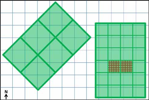
It is also common that multiple flow simulation grids are generated from a unique geological grid (Figure 7, two flow simulation
Let’s imagine a geological model of cell size 50m by 50m horizontally and 1m vertically. The engineer asks for a simulation grid of
(... Continued from page 17)
Figure 5. A) Original 3D geological grid. B) Upscaled 3D simulation grid (4 cells merged into 1 cell).
Figure 6. 3D simulation grid with an LGR.
18 RESERVOIR ISSUE 01 • JANUARY 2016
Figure 7. 3D geological grids versus two local 3D simulation grids.
cell size 100m by 100m horizontally and 3m vertically. We have now a single large cell where there were 12 small ones before. Each small, original cell has its own values of porosity and water saturation. What values should be stored in the corresponding large cells of the simulation grid? These are the questions that property upscaling has to answer. Fundamentally, it is the same problem as upscaling well logs into the cells of the geological grid (Jerome et al, 2015c).We apply some mathematical averaging technique that will compute a value in the simulation grid which will respect the characteristics of the 12 original cells.
For porosity, the upscaled value must respect the cumulated porous volumes of the 12 original cells. Arithmetic average weighted by cell size is usually applied. Upscaling water saturation follows a similar approach. We upscale it by arithmetic average weighted porosity to ensure that the hydrocarbon porous volume of the upscaled cell is equal to the sum of the hydrocarbon porous volumes of the original 12 cells.
One question remains– should we worry about upscaling facies?
Two approaches are used. In the first one (Figure 8, method A), the facies property is being upscaled first, and then the upscaled facies guides the upscaling of the petrophysical properties. The approach is again equivalent to the one used to upscaled facies description from the well into the cells of the geological 3D grid. The upscaled facies is the preponderant one in the original cells. In Figure 8, the upscaled upper cell is the combination of 4 cells of sand and 2 of shale; the upscaled facies takes the value sand. In a similar way, the 2 cells of sand and 4 cells of shale below are replaced by a single cell of shale. For the porosity, upscaling is done by arithmetic average, as explained previously. Only the cells with the same facies than the upscaled one are used. For the upper upscaled cell, it means that the averaging is done using the porosity of the 4 original sand cells. Similarly, the porosity in the lower cell is the average of the porosity in the associated 4 original shale cells. The same filtering technique is applied to compute the average water saturation values. In the second approach (Figure 8, method B), the facies is ignored. The 6 original values of porosity and water saturation are used to compute the average values in each upscaled cell.
The two methods give some significantly different results in situation, such as the one described here where the original cells belong to two different facies. When filtering by the facies, the resulting upscaled porosity and water saturation are characteristic to
what is expected for the respective upscaled facies. The upper upscaled cell is sand and its associated upscaled porosity is around 30%, which is coherent with the values of porosity found on the logs and modeled in the sand facies in the geological grid. The same can be said for the lower upscaled shale cell. On the contrary, with the second method in which facies is ignored, the upscaled values are average of original numbers associated with shale and sand. The upscale cells are not really a sand, nor a shale, anymore. It is an “average facies” of some sort.
Which method is best? It will depend of the reservoirs and the decision should be made by the whole team. The key underlying question is to know which of the two methods creates an upscaled grid which behaves similarly to what would have been observed if flow simulation was run on the original, not-upscaled, geological grid. If time and resources allow, it might good to run flow simulation in a portion of the geological grid (so that flow simulation runs fast). Simulation is done in the original geological grid and it is also run in the flow simulation grid with properties upscaled with the first method, and then with the second method. The method associated to the flow simulation grid behaving the closest to the original geological grid is the one to keep.

Property upscaling is also the time to validate the cell size for the flow simulation grid. We must ensure that the global geological characteristics stored in the geological grid are respected by the flow simulation grid.
For example, imagine an original geological grid showing a sandbar in the middle of a shale geological unit (Figure 9A). If we create a flow simulation grid with very large cells, the sandbar is split in two parts in the simulation grid (Figure 9B). The simulation grid is too coarse to respect the continuity of the sandbar. This would influence greatly the
results of flow simulation. If a flow simulation grid with smaller cells is used (Figure 9C), the continuity is respected.This second simulation grid is more appropriate for this reservoir.
When asked about the cell size for the simulation grid, engineers often answer that they want a grid with as few cells as possible. The geomodeler should help his team to balance this constraint with another important one – the simulation grid must be detailed enough to respect the continuity of the geology of the reservoir.

Not every flow simulation grid is coarser than the geological grid. Sometimes, it is more refined and the properties must be transferred by downscaling instead of upscaling. Upscaling here means finding a single value to replace several original ones efficiently. Downscaling is the opposite –where the geological model is a single cell (50m*50m by 1m vertically for example), we now need values for multiple cells (for example, each of 10m*10m*1m). To do this, two approaches exist (Figure 10).
The first approach is probably the main one used in the industry and it is a very straightforward one. All the small cells of the simulation grid, which fall inside a large cell from the geological grid, are getting the value stored in that large cell. For example, with a sand-shale facies model (Figure 10A), the cells of the rotated flow simulation grid are assigned the facies sand if their center is falling in a sand cell of the original geological grid (Figure 10B, all the cells falling inside the (... Continued on page 20)
Figure 8. Upscaling porosity and SW by Facies versus upscaling the petrophysics without facies upscaling.
RESERVOIR ISSUE 01 • JANUARY 2016 19
Figure 9. A) Facies model in the original 3D geological grid. Facies model in a coarse (B) and in a refined (C) 3D simulation grid.
black shape, delimiting the sand zone of the geological grid).
This approach causes one problem though. Imagine a 50m*50m cell of the original geological grid with a porosity value of 22.4%. Does it really mean that we have a block of rock in the ground of 50m by 50m with a homogenous porosity of 22.4%? If the next cell of the geological grid has a stored porosity value of 30%, does it mean that we have a block of 50m by 50m of 30% porosity in direct contact with the block of 50m by 50m of porosity 22.4%? Obviously not. We believe instead that the porosity is gradually changing from 22.4% to 30%. And yet, downscaling with the approach described in the previous paragraph means that we believe our reservoir to be really made of “homogeneous blocks”. Will the results of flow simulation in such a “blocky” simulation grid be close enough to what is really going to happen during production? If your team answers ‘no’ to this question, a second downscaling approach should be considered. It is a more time-consuming one, but it will allow seeing a different value inside each small cell of the flow simulation grid.
The second approach is based on one observation. When we use geostatistics to populate facies in the geological grid, we are not populating the volume of each cell with facies values. What geostatistical algorithms are really doing is computing a facies value at the XYZ point located at the center of each cell (Figure 10C). We don’t say anything about what should be the facies values in the remaining volume of the 50m by 50m cells.
This fact can be used to our advantage when doing property downscaling. The facies values from the geological grid are painted only in the cells of the flow simulation which contain the center of each original cell (Figure 10D). It leaves a lot of cells with no facies value assigned to them. In a second step, geostatistics are used to populate these cells, using each of the painted cells as a hard data. With this process, facies, and then petrophysical properties such as porosity and water saturation can be downscaled and still show variation from one small cell of the simulation grid to the next. It gives a more realistic tone to the model than the blocky aspect that the first downscaling approach creates.

RANKING GEOMODELS FOR THE PURPOSE OF FLOW SIMULATION
The previous section describes the fundamentals of creating the geometry of a flow simulation grid and how to transfer facies and petrophysical properties. One big issue remains. What do we do when we have created hundreds of geological models, each one made of a 3D distribution of facies and of 3D distributions of petrophysics. Do we give only one to the simulation engineer? Do we give several realizations? And, depending upon the approach, which of the hundreds shall we give? Do we transfer all the realizations? Answering the last question is the easiest one. No, we do not transfer all the realizations (much to the relief of our engineers!). If each realization takes hours, days or even weeks to run, one can only imagine how long it would take to run all of our realizations.
In that case, should we send just one then? This approach is still used a lot. It tends to be part of some discussion between the geomodeler and the engineer which goes like this: “I have hundreds of realizations, which ones do you want?”... “Hundreds!?!?! I can’t run flow simulation on hundreds of realizations! Give me just one, the one you want!” And it is up to the geomodeler to pick one. Of course, it is possible to pick just one. We can use the concept of ranking that we’ll cover in the next few paragraphs. But, is this acceptable? Providing only one to the engineer means that we suddenly ignore all the uncertainty we have identified with the geoscientists. The model is now completely deterministic, giving a false sense of certainty to the engineers, to the team and to the decision-makers of our companies. How tempting it might be to send only one model to flow simulation; the team and the company will make more grounded decisions about the reservoir if the geological uncertainties are taken into account in flow simulation. We can’t just send one realization. We need to send several of them to sample adequately the geological uncertainty space. The question is to know which realizations.

(... Continued from page 19)
Figure 10. A) Facies model in the original 3D geological grid. B) “block” downscaling in the 3D simulation grid. C) Facies model in the original 3D geological grid in cell-center view. D) “center-to-center” downscaling in the 3D simulation grid.
20 RESERVOIR ISSUE 01 • JANUARY 2016
Figure 11. Facies distribution. Base case scenario with no connectivity between the sands.
The most common approach is to use the in-place volume, specific to each realization as a guide. The use of geomodels in reserve computations will be detailed in the next paper of this series. Hereafter, the topic is covered in very simple terms.

Figure 11 represents the base
a sand-shale reservoir (a variation of the example used in Figure 3 and Figure 4 ). The thickness of the shale separating the sands 2 and 3 is uncertain. It could be thinner (Figure 12A) or thicker (Figure 12B). In the first case, the in-place volume is higher than in the reference model, while it is lower in the second case (a thicker shale means less sand in sands 2 and 3).The in-place of the reference model is in the middle of the range. If a single model is sent to flow simulation, it might be tempting to send the reference case; if the in-place volume is an average of the in-place volumes of all the realizations, it is tempting to assume that this specific realization is also going to behave in an “average” way in terms

of flow simulation. If we have hundreds of realizations and the two examples shown in Figure 12A and Figure 12B are two extreme in-places, then, following the same logic, we might send the three realizations to flow simulation. We might expect that the model showing a low in-place volume will show less production than the reference case which itself will be less performant than the model showing a high in-place volume.
Unfortunately, ranking realizations based on in-place volumes can be misleading because in-place volumes tell nothing about the connectivity in the reservoir. Connectivity is a key controller in flow simulation.
Let’s consider some new variations around the reference case. This time, the uncertainty is in terms of the continuity of the different shales. Do we really have continuous shales isolating completely the different sands, as in the reference case (Figure 11)? Or, are the shale discontinued and the sands connected? Figure 13 shows two scenarios where the sands are more (Figure 13A) and more (Figure 13B) connected. These two new realizations might have in-place volumes very similar to the in-place volumes of the reference case. Nevertheless, in terms of flow simulation, they will behave completely differently from the reference case. Without digging more about the consequence in term of flow simulation, we can easily imagine that the sands in the reference case will need to be produced independently one from the other, while connected sands might be produced as one block.
sands with a lot of shale (Figure 12B as well as upper left model in Figure 14), a realization of isolated sands with less shale (Figure 12A as well as upper right model in Figure 14) and lastly, two models of connected sands, where the level of connection keeps increasing from model to model (Figure 13 as well as the middle and lower central models in Figure 14). Which ones shall we send to flow simulation? Changes in connection have a larger impact than changes in in-place volumes. It is preferable to send the reference case and the two models of connected sands. The reference case is expected to be a pessimist case in terms of flow simulation, because of the low level of connectivity, while the highlyconnected model is expected to be the more optimistic scenario.
Figure 14 is the opportunity to see how information, provided by the geoscientists, is translated into geomodeling constraints which will lead to different results of flow simulation. On one hand, uncertainty in the sand proportions will lead to adding uncertainty in the input facies proportions used in geostatistical algorithms such as SIS (Sequential Indicator Simulation). This uncertainty will impact mostly the output range of in-place volumes. On the other hand, uncertainty in how the sands are connected will lead to adding uncertainty in the dimensions of the variograms used in geomodeling. The space of uncertainty in this simple example is the two-dimension space with sand proportion on one axis and connectivity on the second.

Now, we have five realizations. The reference case, (Figure 11 as well as upper central model in Figure 14), a realization of isolated
Quantifying the level of connectivity and understanding its correlation to flow
case realization of
Figure 14. Translating the geosciences scenarios into geomodeling constraints and their impact in engineering terms.
Figure 12. Facies distribution. Alternative scenarios with more (A) or less (B) Sand than in the base case (Figure 11).
RESERVOIR ISSUE 01 • JANUARY 2016 21
Figure 13. Facies distribution. Alternative scenarios with some (A) and a lot (B) of connectivity between the sands.
simulation is still a topic of active research. A bibliographic review would be in order to understand how it is applied in the type of reservoirs studied by your team.
Another approach to ranking is to run streamline simulation (Figure 15) on as many of the geomodel realizations as possible. Streamline is a type of simplified simulation which runs much faster than full, true flow simulation. Streamline simulation could be used to evaluate how the different realizations are going to behave. From there, a few realizations are picked and sent to true, intensive flow simulation computations. More approaches exist to rank based on expected behavior in flow simulation. Geomodelers should discuss the topic with their reservoir engineers to see which one(s) seem(s) more appropriate to the project at hands.
realizations, are sent to flow simulation.
For all these reasons, if reservoir engineers are involved in the geomodeling project, it is essential to communicate with them as often as possible.
The next paper will focus on the use of geomodels as inputs for in-place volume computations.
TO GO BEYOND
Many geomodeling packages have tools to create simulation decks, run simulation in the background by calling the flow simulation software and then display the time-dependant results. It might be interesting to discuss about these tools with the engineers. Similarly, flow simulation software can compute statistics on the properties, as well as run some geostatistics. The geomodeler

CONCLUSION
Improving communication between the geomodeler and his team is a topic discussed in all the papers of this series. However, if the geomodeler has to pick one place where improving the communication might have the biggest impact, he should focus on the one with the reservoir engineers. Firstly, the communication between geoscientists and engineers are often challenging, and the communication around a geomodeling project will be no exception, unless attention is given to this challenge. Secondly, transferring the information from the geological model into the flow simulation grid is the moment where considerable knowledge about the reservoir can be corrupted or even lost. If the upscaling is not done properly, the upscaled grid might not reproduce well enough the behavior expected in the geological grid. Also, it is the moment where all the uncertainty identified by the geoscientists might get lost if the wrong realizations, or if not enough
should get familiar with these. It will give him a better idea of how the engineer will review his model and how he might edit it. When a field has had some production, running flow simulation starts with history matching. The goal is to validate and edit, if need be, the geomodel and the input dynamic parameters so that the engineers can reproduce the past production in their simulation. Once done, they can move to forecasting how the field’s production will evolve moving forward. For more details about this important topic, the reader can refer to (Gilman and Ozgen, 2013) or (Oliver et al., 2008).
For more details about some techniques of ranking, the reader can refer to (Datta-Gupta and King, 2007) and (Jamshidnezhad, 2015).
REFERENCES
Datta-Gupta, A. and King, M. J., 2007. Streamline Simulation: Theory and Practice. SPE Textbook Series, Vol. 11. SPE. 394 pages.
Gilman, J. R. and Ozgen, C., 2013. Reservoir Simulation: History Matching and Forecasting. SPE. 120 pages.
Jamshidnezhad, M., 2015. Experimental Design in Petroleum Reservoir Studies. Gulf Professional Publishing. 176 pages.
Jerome T., Yang, J. and Gentile, S., 2015a. Geomodeling: a Team Effort. Part 2: the Geomodeling Workflow. The Reservoir Magazine, CSPG, March 2015.
Jerome T., Gentile, S. and Yang J, 2015b. Geomodeling: a Team Effort. Part 3: Geostatistics.The Reservoir Magazine, CSPG, April 2015.
Jerome T., McLean, J.K. and Chan, L., 2015c. Geomodeling: a Team Effort. Part 5: Petrophysicists and Geomodeling. The Reservoir Magazine, CSPG, April 2015.
Lavoie, R. and Thenin, D., 2013. Waterflooding Tight Oil Fields: The Static and Dynamic Modeling Aspects. RPS L&L series, Sep 2013.
Oliver, D. S., Reynolds, A. C. and Liu, Ning, 2008. Inverse Theory for Petroleum Reservoir Characterization and History Matching. Cambridge University Press. 380 pages.
THE AUTHORS
Feel free to contact the authors about this paper or about the series.
Thomas Jerome is the Calgary manager of the Reservoir Modeling team in RPS (Thomas.Jerome@rpsgroup.com). Geologist by background, Thomas has spent the last 15 years working on geomodeling projects, first in Middle-East and in Calgary, Canada, since 2008. He has worked on conventional and unconventional reservoirs, both Canadian and international. Thomas is leading this CSPG’s series on Geomodeling.
Samaneh Razzaghi is a Senior Reservoir Engineer with Encana Service Company Ltd. (samaneh.razzaghi@encana.com). She holds a Ph.D in Reservoir Engineering and has more than 10 years of experience in Numerical Reservoir Modeling. Samaneh has worked on both conventional and unconventional reservoirs such as Shale gas and Oil Sands in the WCSB, and Light Oil Carbonate Reservoirs in the Middle East.
Martin Malek is a Senior Development Engineer for Tamarack Valley Energy Ltd (Martin.Malek@TamarackValley.ca). Since graduating from the University of Calgary, Martin has worked in both subsurface and production capacities in the WCSB and Permian Basin in Texas. The majority of his expertise has been in development of unconventional reservoirs such as the Wolfcamp in Texas, and Cardium in Alberta.
22 RESERVOIR ISSUE 01 • JANUARY 2016
Figure 15. Example of streamline simulation (Lavoie and Thenin, 2013). Image courtesy of RPS.
STRUCTURE SEMINAR AND FIELD TRIP: Tribute to Dr. Deborah Spratt, September 18-19, Canmore, Alberta
By Pat Fothergill

In September, the Structural Division of the CSPG held a special 2-day event in tribute to Dr. Deborah Spratt. Dr. Spratt started her career at the University of Calgary in 1980 and retired in 2011. During her three decades as
a professor of structural geology at the U of C, Dr. Spratt supervised a number of successful master’s and PhD candidates.
Sixteen of Deborah’s former students, colleagues and friends gathered in Canmore on
September 18 and 19. On Friday the 18th, the group convened at the Mystic Springs Chalet. The seminar presentations and discussions covered a number of topics related to surface and subsurface structural geology, with a number of examples from the Canadian Rockies, as well as the Valhalla Complex of southeast British Columbia, and the fold and thrust belt of Pakistan.
The following day Dr. Spratt led a field trip to her favourite outcrops in the Kananaskis and Bow Valleys. Following a theme of fault-related folding of the Front Ranges, Deborah pointed out a number of salient structural features. Dr. Philip Simony, who was Dr. Spratt’s colleague at the U of C for many years, provided additional commentary.
The weather was dry and the sun peeked through the clouds a few times. The autumn wind was funneled through the mountain valleys, making it very difficult to hold onto paper maps and sections. In typical fashion of the Structural Division, we had to forsake extended discussions in order to cover the field trip itinerary.
The event was organized by Deborah Sanderson, Rob Taerum, Melissa Newton and the Structural Geology Division Committee.


|
1602 – 5th St N.E. Calgary, AB. T2E 7W3 Phone: 403-233-7729 www.tihconsulting.com e-mail: tih@shaw.ca T.I.H. Consulting Ltd. Geologic Well-Site Supervision Geological Consulting Services for 35 years Wellsight geological supervision and coring Geo-steering, Petrographic and Sample Studies Conventional & Heavy Plays | SAGD Projects Domestic and International Operations Moh & Associates Oilfield consultants Ltd. Since 1980 Moh Sahota, B.Sc (Hons), M.Sc. President Ph: 403.263.5440 Email: info@mohandassociates.com www.mohandassociates.com
Shop
Group photo taken in front of the “knuckle folds” of Mount Kidd. Dr. Deborah Spratt centre front
Rock
2015 CSPG Awards
TECHNICAL AWARDS
Stanley Slipper Gold Medal for outstanding Career Contributions to Oil and Gas Exploration in Canada
Richard Walls
R.J.W Douglas Medal for Outstanding Contributions to the Understanding of Sedimentary Geology in Canada
Don Kent
Honorary Membership for Distinguished Service to the Society
Dale Leckie
Link Award for Best Presentation–Technical Luncheon Series
Lindsay Dunn
Medal of Merit for Best Paper Related to Canadian Petroleum Geology
Ken Gray
Jen Russel-Houston
VOLUNTEER AWARDS
President’s Award for Outstanding Service by a CSPG Member
Paul MacKay
H.M. Hunter Award for Distinguished Service to the Society
Astrid Arts
Kevin Root
Tracks Award for Members Who have Set New Standards of Excellence
Samantha Etherington
Andrew Fox
Raymond Geuder
Ian Kirkland
Partner Tracks Award for Associations, Companies or Institutions That Have Contributed to the Society’s Pre-eminence, Welfare and Reputation
Alberta Core
Research Centre
Service Awards
for Members who have Served the Society for over Five Years
James Ablett
Linden Achen
Norbert Alwast
Alexis Anastas
George Ardies
Peter Aukes
Bill Ayrton
Olena Babak
Jim Barclay
Ali Beken
Philip Benham
Barry Bennett
Khaled Benzaoui
Tim Bird
Graeme Bloy
Darin Brazel
Carson Brown
Chuck Buckley
Jean -Yves Chatellier
Burns Cheadle
Guoxiang Chi
Richard Chisholm
Nancy Chow
Andre Chow
Penny Christensen
Shawna Christensen
David Clyde
John Cody
Doug Colvin
Andrew Cook
Thomas Cox
Barrie Dargie
Tim De Freitas
Foon Der
Ian DeWolfe
Steve Donaldson
Tina Donkers
Eva Drivet
Dave Drover
Kyle Durocher
Markus Ebner
Richard Evoy
Peter Fermor
Patrick Fothergill
Jocelyn Frankow
Lloyd Freeman
Riona Freeman
David Garner
Sasan Ghanbari
Chad Glemser
Darcie Greggs
Tony Hamblin
Tim Hartel
Peter Hay
Brad Hayes
Simon Haynes
John Hogg
Norman Hopkins
Kristy Howe
Stephen Hubbard
Ian Hutcheon
Dale Issler
Wim Jalink
Samantha Jones
Peter Kouremenos
Shawn Lafleur
Craig Lamb
Larry Lane
Sid Leggett
Alex MacNeil
Leena Markatchev
Darin McCollum
Heidi McDonald
Ian McIlreath
Ben McKenzie
Margot McMechan
David Middleton
Stephen Minions
Ryan Mohr
David Morrow
Jon Noad
Brett Norris
Rob North
Kirk Osadetz
Brenda Pearson
John Peirce
Guy Plint
Kyla Poelzer
Frank Pogubila
Brian Pratt
Weishan Ren
Claude Ribordy
Cindy Robinson
Terry Sami
Chris Seibel
Megan Simons
Heather Slavinski
Randy Smith
Tom Sneddon
Vern Stasiuk
Glen Stockmal
Naomi Storey
Martin Teitz
Scott Thain
Damien Thenin
Richard Thom
Clint Tippett
Elizabeth Turner
Christian Viau
John Waldron
Michael Webb
Gerald Wendland
Marissa Whittaker
Gordon Williams
Jay Williams
Andrew Willis
Dan Wright
Keith Yaxley
Colin Yeo
Volunteer Awards for Members who have Served the Society for up to Five Years
Lindsey Abbott
Rachael Acker
Leye Adeboye
Andres Altosaar
Paul Anderson
Kyle Anderson
Ryan Axani
Kelly Batten Hender
Jessica Beal
Nadine Beaudoin
Alicia Bjarnason
Jeff Boissonneault
Mary Luz Borrero
Karen Bradshaw
Sonia Brar
Ryan Brenner
Harrison Brown
Gary Bugden
David Chunn
Michelle Clements
John Cockbill
Craig Coulombe
Noel Devere-Bennett
David Dolph
Ruben Dominguez
James Duggan
Paul Durkin
Hayley Edwards
Nanna Eliuk
Mona Enachescu
Marc Enter
24 RESERVOIR ISSUE 01 • JANUARY 2016
Colin Etienne
Curtis Evans
Duncan Findlay
Amy Fox
Jason Frank
Jean -Francois Gagnon
Robert Gardner
David Gardner
Dan Gee
Meriem Grifi Dennis
Torrey Hallan
Dale Hardcastle
Caterina Heikkinen
Brian Hester
Gemma Hildred
Travis Hobbs
Amir Hosseini
Nicole Hunter
Natalya Ionkina
Art Irwin
Biyi Ishola
Bryce Jablonski
Erin James
Adriana Jerez
Jassie Kang
David Keighley
Melanie Klucker
Jürgen Kraus
Melissa Kuechler
Ross Kukulski
Brent Kuntz
Cheryl Kuyten
Stan Lavender
Jason Lavigne
Michael Le
Janice LeDrew
Carmen Lee
Paul Levesque
Jaime Lo
Adam MacDonald
Sabita Makoon -Singh
Heather Makowecki
Vanessa Marcheggiani -Croden
Ryan Martin
Jane Marzetti
Adrienne McDougall
Jayd McGrath
Rob McGrory
Ryan McKay
Les McMillan
Megan Miller
Keith Millis
Christopher Morgan
Kevin Morrison
Mike Mueller
Jacey Neumann
Rachel Newrick
Melissa Newton
Eric Niven
Jennifer Noade
Darcy Novak
Taylor Olson
Gerald Osborn
Lauren Ostridge
Robert Panek
Rob Paul
Laura Pecharsky
Kelsea Pedersen
John Perrin
Russ Phillips
George Pinckney
Sharlene Pollock
Andrei Popescu
Mary-Ellen Price
Adam Pugh
Mark Radomski
Elwin Reichert
Kristin Rohr
Alex Romanov
Katie Romansky
Renu Sahota
Cynthia Sawatzky
Armin Schafer
Emily Schellenberg
Tyler Schmidt
Jesse Schoengut
Nicole Sendziak
Colleen Sherry
Jared Shivak
Jason Shtand
Angie Simpson
Darren Singleton
Chad Sisulak
Brant Skibsted
Catherine Skilliter
Kelly Skuce
Warren Smart
Geoffrey Speers
Janelle Springer
Tony Stadnyk
Tassia Stainton
Chris Steinhoff
Rudy Strobl
Brodie Sutherland
Amy Switzer
Ryan Szol
Mark Thomas
Eric Thornhill
Brian Tuffs
Allan Turner
Vic Urban
Pei-Ling Wang
Neil Watson
Paul Webster
Courtney Whibbs
Samuel Williams
Melissa Williams
Jamie Wills
Andrew Wiseman
Heather Wright
Hong Yang
Denise Yee
Tanya Yeomans
Calista Yim
Yi Zhao

2016 CSPG Squash Tournament Registration Open! When: February 4-6th, 2016 Where: Bow Valley Club | 250 6 ave SW Calgary For more information and to register online go to www.CSPG.org Early Bird registration ends on January 7th Registration deadline is Wednesday January 27th @4:00pm RESERVOIR ISSUE 01 • JANUARY 2016 25
IN MEMORIUM Art Shepard
|
By Doug Hayden, Chair, CSPG Core and Sample Division (Edited by Steve Lynett)

In June, the Geological community marked the passing of Art Shepard, a man whose innovative ideas and unswerving dedication made a significant contribution to our understanding of the geology of Alberta. Hired in 1962 by the Energy Resources Conservation Board (ERCB), Art spent the next 30 years establishing Alberta as a world leader in core research facilities. Art’s first assignment with the ERCB was to organize a storage and viewing facility for core, drilling tours and drill cuttings. Not one to waste time, he oversaw the move of core material from the basement of the downtown Calgary ERCB head office to a new storage facility within the University of Calgary’s Research
Park. There, he began a process of continuous improvement and innovation for storage and viewing of core and cuttings. In 1984, Art’s imagination and innovative ideas were on full display when the Core Research Centre opened its doors. Geologists were treated to a world-class expansion that included height-adjustable core tables with specialized lighting; new capabilities for slabbing and small plug coring as well as high-efficiency washing systems for drill cuttings. With the introduction of computers the Core Research Centre, under Art’s leadership, developed a cataloging system that allowed fast and efficient retrieval of material. For many years, and to this date, members of the geological community travel from the far corners of the world to tour the ERCB (now AER) Core Research Centre, recognizing it as a model for state-of-the-art core facilities.As any geologist who had the good fortune to work with Art will tell you, he ran a tight ship that provided his clients with the highest level of service and access to core and cuttings. His respect for the geologists and the often-difficult jobs they had to do was evident in the worldclass facilities he created to support them. He also worked closely with the Canadian Society of Petroleum Geologists (CSPG), helping host annual core conferences, as part of the annual CSPG conference, the largest of which was held in 1988. Art’s management style was often described as ‘old school’ –task oriented and no nonsense. While his staff addressed him as Mr. Shepard, he always
treated them with respect and was quick to acknowledge a job well done. In his 30 years with the ERCB / AER, Art naturally dealt with regular staff turnover, as his people moved on to other departments with the board or out into industry. Rather than complain that he was losing good people, he celebrated their success and wished them well. Behind his serious façade, Art was very much a people person and placed great value on the individual. When Art retired from the ERCB in 1992, he quickly took up a new challenge, partnering with Joe Morris of Petrocraft, and later his son, Russ to form Datacon, a company that consulted in the design and construction of core storage facilities around the world. Together, they consulted on the design of over 10 new facilities in Europe, the Middle East, Cuba, and South America. Not one to mince words, Art gave his clients the best advice possible, even if that advice was contrary to plans that were already in place. Arts commitment and passion to running world-class core repositories stayed with him through his final days. During visits with Art in his home towards the end of his life, Arts daughter, Colleen Skelton, listened to his concerns that there were boxes of core at the research centre that might be lost if they weren’t moved to the proper bins. The geological community can be very proud of Art Shepard and the legacy he has left. He will be remembered with respect and gratitude. Doug Hayden, Chair, CSPG Core and Sample Division (Edited by Steve Lynett)

2016 BOARD OF DIRECTORS


Education: B.Sc. Geology, University of Ottawa (1983); M.Sc. Geology, Washington State University (1985) Ph.D. Geology, University of Alberta (1989).
Experience: Shell Canada Ltd (1998 -present); Geological Survey of Canada (1989 -1998).
Professional Memberships: CSPG, APEGA
Volunteer Work: CSPG/CSEG/CWLS GeoConvention General Co -Chair: Integration (2013); Geoconvention Partnership Agreement Committee (2012 -2013); GeoCanada 2010 Convention Organizing Committee; CSPG Finance Director (2010 -2011); Earth Science for Society Committee (2009 -2010); CSPG Trust Fund Committee (2007 -2009); CSPG Outreach Director (20072009); CSPG Bulletin Associate Editor (2001 -2007); SIFT Fieldtrip Leader (1999 -2005); CSPG speaker and chair at several conventions and luncheons; 20 refereed publications within and outside CSPG.
Awards: CSPG Volunteer/Service Awards; CSPG Tracks Award.


Education: B.Sc. (Hons) Geology, Imperial College London (1974); PhD. Geology, University of Bristol (1985)
Experience: VP Ease & New Ventures - EnCana Corporation (2002 -2008); Structural Geology SpecialistPanCanadian Petroleum (1994-2002); Structural Geology Specialist - British Petroleum (1985 -1994); College Lecturer in Geology - University College Cork (1980 -1985)
Professional Memberships: CSPG, APEGA GSL
Volunteer Work:
GeoCanada 2010 - CSPG Co-chair (2009-2010), Joint Annual Convention 2006 –CSPG Cochair (2005-2006), GeoCanada 2000 - CSPG Technical Co -chair (1999-2000), Publications Committee (1995 -1999), Link Award Lecture Tour (1998)
Awards: 2010 President’s Award, 2006 President’s Award, 2003 Tracks Award,2000 Tracks Award, 1998 Link Award, Service/Volunteer Awards


Education: B.Sc. Geology, University of Sask. (1985); Ph.D. Geology, University of Sask.(1992).
Experience: VP Geosciences, Thunder Energy Trust/ Sword Energy/Journey Energy (2006 -2015); Geoscience Manager, Thunder Energy Trust (2005 -2006); Geologist, Impact/Thunder Energy (2001 -2005); Geologist, Startech (2000 - 2001); Geologist, Anderson Exploration (19972000); Geologist, PanCanadian (1991 -1997).
Professional Memberships: CSPG, AAPG, APEGA, CSEG
Volunteer Work: CSPG East Coast Ambassador (2013); 2010 GeoCanada Convention (2010); CSPG Committee on Conventions/JACC (2005 -2010); CSPG Webcasts Program (2003 -2004); Tech Lunch Committee Chair/ Link Committee (2002 - 2005); CSPG Program Director (2001); CSPG Services Director (1998 -1999); Convention Technical Committee and session Chair (1988); Student Industry Field Trip Committee member/Chair (1991 -1996); CSPG Member since 1984.
Awards: CSPG Presidents Award 2009; CSPG Volunteer Award; CSPG Services Award; CSPG Tracks Award.
RESERVOIR ISSUE 01 • JANUARY 2016 27


Education: B.Sc. Geography, Simon Fraser University (1998); M.Sc., Earth Sciences, Simon Fraser University (2000).
Experience: Long Run Exploration (2014-present); Surge Energy (2011 -2014); Encana Corporation/Pan Canadian (2000 -2011).
Professional Memberships: CSPG, APEGA, CWLS, SEPM.
Volunteer Work:
CSPG Executive – Program Director (2009 -2011); Technical Program Chair 2008 CSPG/CSEG/ CWLS annual Joint Convention; CSPG Committee on Conventions – now JACC (2004 -2006 & 2009-2011); Chair (2yrs) and Co-Chair (2yrs) of the CSPG Sedimentology Division (2001–2004); Student Industry Field Trip (SIFT) – Clastic Core Workshop (2001 -2003).
Awards: CSPG Volunteer/Service Awards; CSPG Graduate Student Award – Best Msc. Thesis - 2001.

Education: B.A. (Honours, Geology/Geography), McMaster University, Hamilton, Ontario (1985). Masters Geology, McMaster University, Hamilton, Ontario (1987)
Experience: Manager Development Geology NAL Resources (2015 -present), Exploration Manager EOG Resources Canada (2011 -2015), Exploration Manager Horn River Division EOG Resources Canada (2010 -2011), Geological Advisor Horn River Division EOG Resources Canada (2009 -2010), Team Lead Peace River Arch/BC North Enerplus (2006 -2009), Clastic Specialist EOG Resources Canada (2004 -2006), Exploration Lead Geologist, PanCanadian Petroleum/ Encana (2002-2004), Senior Oil Development Geologist PanCanadian Petroleum (19972002), Geologist, Petroleum Recovery Institute (1988 – 1997).
Professional Memberships: CSPG, AAPG, APEGA
CSPG Volunteer: Session Chair Devonian Mississippian Unconventional (2013), Thesis Awards Committee (1989 -1992)
AAPG/SPE Volunteer: Field trip Logistics AAPG conference 1992 Organizing Committee SPE/CIM/Canmet Horizontal Well Conference 1994, 1996 Board of Directors Canadian SPE 1998 -2003
Awards: CSPG Service Award (1992)


Education: M.Sc Geochemistry, University of Calgary
Experience: Rakhit Petroleum Consulting, Petrel Robertson, PanCanadian/EnCana, EOG, MGM Energy, Statoil Canada - Currently Exploration Advisor, East Coast Exploration
Professional Memberships: CSPG, AAPG, APGEA
Volunteer Work: General Co -Chair 2012 GeoConvention -Vision, Technical Program Chair 2007 CSPG/CSEG/ CWLS annual Joint Convention, Conference Chair: 2004 Gussow Geoscience Conference, GeoCanada 2000, CSPG Committee on Conventions
Awards: CSPG Tracks Award 2012, CSPG Best Student Poster 1995, CSPG Volunteer/Service Awards
28 RESERVOIR ISSUE 01 • JANUARY 2016


Education: B.Sc. (Honours) Geology, University of Wales (1989); M.Sc. Geology, University of Alberta (1992); Ph.D.Geology, University of British Columbia (1997).
Experience: Senior Geological Advisor, Athabasca Oil Corporation (2014 -2015); Geoscience Manager, Athabasca Oil Corporation/Brion Energy (2007 -2014); Staff Geologist, Shell Canada Ltd. (2002-2007); Geologist, Total S.A. (1997 -2002).
Professional Memberships:
CSPG, AAPG, APEGA, CHOA, CWLS, SEPM.
Volunteer Work: Basin Analysis and Sequence Stratigraphy Technical Division Co -Chair (2004 - Present); CSPG GeoConvention Session Co-Chair (2004-2014); CSPG Core Convention Co -Chair (2004).
Awards: CSPG Volunteer Award (2007); CSPG Service Award (2009, 2010, 2011, 2012, 2013).

Education: B.Sc. Honors Geology, University of Alberta (2006); M.Sc. Earth and Atmospheric Sciences, University of Alberta (2010); P.Geo.
Experience: Petrophysicist, Nexen Energy ULC (2012 - Present); Exploration Geologist, Talisman Energy Inc. (2011-2012); Petroleum Geologist, Northwest Territories Geoscience Office (20102011).
Professional Memberships:
CSPG, AAPG, APEGA, CWLS
Volunteer Work: ‘On Belay’ Session Chair, 2014 GeoConvention (2014); bicisport Calgary Cycling Club (2014); Lead, Canada Region Young Professionals AAPG (2010 -Present); Vice President / Treasurer, Canada Region of the AAPG (2013 -2014); Secretary / Forman, Canada Region of the AAPG (2012 -2013); Delegate, Canada Region of the AAPG (2012 -Present).
Awards: Best Student Core Presentation, 2008 GeoConvention.


Education: B.Sc. (Honors) Geology, Queen’s University (1995); B.Ed, Ottawa University (1996); Ph.D. Geology, Dalhousie University (2001).
Experience: VP – Geoscience, Osum Oil Sands Corp. (2008 - Present); Subsurface Team Lead & Geologist, Shell (2001-2008).
Professional Memberships:
CSPG, AAPG, IAS, SPE.
Volunteer Work: Associate Editor, Bulletin of Canadian Petroleum Geology (2010 – Present); Volunteer Committee (2012 -2013).
Awards: Volunteer Award (2012 -2014).
Education: B.Sc. Earth Science, Simon Fraser University (2009).
Experience: Jupiter Resources (2014 -Present); Petroamerica Oil Corp. (2014); Suroco Energy (20112014); Encana Corporation (2009 -2011).
Professional Memberships: CSPG, AAPG, APEGA
Volunteer Work: GeoConvention 2014 Technical Co-Chair.
Awards: Tracks Award (2014).
RESERVOIR ISSUE 01 • JANUARY 2016 29
CORPORATE SUPPORTERS
RIGSAT Communications
Pason System
CMC Research Institutes, Inc.
Big Guns Energy Services
Earth Signal Processing Ltd.
Canada Brokerlink Inc.
ITG Investment Research
Nalcor Energy
Paramount Resources
Pulse Seismic Inc
Compass Directional Services
EV Cam Canada Inc.
Lee Energy Systems
RPS Energy Canada Ltd.
Birchcliff Energy Ltd.
Sproule Associates Limited
Waterline Resources
Cabra Consulting Ltd.
McDaniel & Associates Consultants Ltd.
National Oilwell Varco
Roke Technologies Ltd.
Signature Seismic Processing Inc.
Navigator Resource Consulting
NExT- A Schlumberger Company
Richardson GMP
Surge Energy Inc.
Valeura Energy
Statoil Canada
Mundiregina Resources Canada
Mcleay Geological Consultants Ltd.
Enviro-Tech Surveys Ltd
Tucker Energy Services Canada
Gaffney, Cline & Associates
Bounty Developments Ltd.
Franconia Geoscience
GeoChemTech Inc.
Prospect Drivers Inc.
HONORARY MEMBER Kirk Osadetz

Kirk Osadetz earned his B.Sc. in Geology from the University of Toronto in 1978, and then his M.Sc. in 1983 from the same institution, after completing a thesis on Eurekan Structures of the Ekblaw Lake Area, Ellesmere Island. He joined CSPG in 1991, and has been a very active member ever since. He started as the Assistant Treasurer (1992) and then became the Treasurer (1993). He was the Core Conference Chair of Pools ’96, and then the Technical Program Co-Chair of the Diamond Jubilee Convention (2002) and the Joint CSPG-CSEG-CWLS Annual Convention (2006). He has Co-Chaired the Convention Technical Luncheon and Programs Committee (1994 – 1997), CoCovenanted the International Lithosphere Program Workshop on Tectonostratigraphic Events at Continental Margins and their Significance for Hydrocarbon Resources in Quebec (2006) and Co-Covenanted of the Third Symposium on Resource Assessment Methodologies in Canmore (2010). Kirk was the Associate Editor of the Bulletin (2001 – 2008) as well as the Guest Editor for several thematic issues (2010, 2012) and has presented twice at Gussow Geoscience Conference (2007, 2013). His three year Executive term was centred on his 2011 Presidential year, and he has been a Trustee for the CSPG Foundation since 2012. Kirk has won a Service Award (2006), two Tracks Awards (1997, 2002), three Volunteer Awards (1996, 2001, 2007), the H. M. Hunter Award (2008) and the President’s Award (2012).
As well as CSPG, Kirk has served on the Petroleum Technology Alliance of Canada
(PTAC) and the American Association of Petroleum Geologists (AAPG) in numerous capacities and won several awards. He has also been the Vice President of the Brentwood Community Association since 2012.
Mr. Osadetz started his career in 1978 as a Junior Exploration Geologist with PetroCanada. After finishing his M.Sc., he worked at Gulf Canada for two years before joining the Geological Survey of Canada, where he worked for 30 years. He progressed from a Physical Scientist, to the Acting Head of Petroleum Resources to the Head of the Energy Geoscience Subdivision. In 2013, he became Programs Development Manager of the Carbon Management Canada Research Institutes and the Containment and Monitoring Institute, a company that is developing technology and practise that assists corporations dealing with carbon management and subsurface containment issues and requirements. Kirk has led and worked on teams in the characterization, computerized modelling and qualitative and quantitative assessment of petroleum systems, their regional resources and environmental impacts. He has experience with unconventional, offshore and frontier resources, and has done wide ranging field work.
Kirk has published extensively, more than 130 scientific publications, on topics ranging from oil families, natural gas seepage, gas hydrate distribution and geological resource assessment. He also contributed to the Geological Atlas of the Western Canada Sedimentary Basin as well as to Mineral and Energy Resource Assessments used to define National Parks and National Marine Conservation Areas. Mr. Osadetz has led field trips, taught CSPG short courses, taught in China and was a mentor for SAIT’s Petroleum Technologist technical writing program.
Kirk Osadetz is an internationally recognized sedimentary basin geoscientist and a leader in Calgary’s geoscience community. He has been an active volunteer for more than 20 years, winning eight CSPG awards and unquestionably leaves a mark on the Society. CSPG is pleased to welcome Kurt Osadetz to the ranks of Honorary Members.
AS OF NOVEMBER 25, 2015
30 RESERVOIR ISSUE 01 • JANUARY 2016


The vision and goal of the Canadian Society of Petroleum Geologists (CSPG) is to make the Core Conference the signature post-session of the AAPG 2016 Annual Convention & Exhibition (ACE), being hosted in Calgary, Alberta, Canada . The theme for the 2016 International Core Conference, "Redefining Reservoir: Core Values”, will reflect the key geologic value we all share: the rocks tell the most important stories in our hydrocarbon quests!
2016
INTERNATIONAL CORE CONFERENCE
Dates: June 23rd-24th, 2016
Time:
Thursday: 8 AM to 4 PM
Friday: 8 AM to 3 PM - CoreMeltdowntoFollow
Location: AER Core Research Centre
3545 Research Way NW, Calgary, AB, Canada
Fee: $195 US (includesCoreMeltdownticket)
$25 US for Core Meltdown only

If you haven’t been to a Core Conference before, you are in for a treat! The conference will be held in the world-class AER Core Research Centre that will accommodate over 30 core displays and accompanying posters over the two-day event. Exhibitors provide scheduled talks summarizing their displays and remain with their core to discuss concepts and features. This year we will host cores from all over the globe – Turkey, Brazil, Germany, and North America. Displays will include both conventional and unconventional plays; siliciclastics, carbonates and evaporates, shales, oil sands, as well as some displays relating to carbon capture technology. We hope you will extend your stay in Calgary to attend this two-day post-ACE Core Conference on June 23rd and 24th, 2016!

CORE MELTDOWN 2016
AGAT Rocky Mountain Saloon
Don’t miss out on the tradition – join us for the Core Meltdown at this year’s AGAT Rocky Mountain Saloon. After two days of technical discussion and demonstration, come enjoy Calgary’s Western Heritage at our rain or shine tent event. Live music, food, and beverages make this event the perfect way to finish off the week. Admission and two drink tickets are included in the conference fee. Tickets for the Core Meltdown only may also be purchased separately. Hope to see all you cowboys and cowgirls there!

RESERVOIR ISSUE 01 • JANUARY 2016 31
BMO Centre at Stampede Park
REGISTER NOW
• 300 Technical Presentations
• 450 Poster Presentations
• 15 Field Trips
• 16 Short Courses
• International Core Conference

Plan now to attend the premier forum of scientific excellence and professional camaraderie for the global petroleum geosciences community to share breakthroughs and innovative solutions.
ACE.AAPG.org
