GENERALINSTRUCTIONS
IMPORTANTNOTICE
AllmaintenanceandrepairoperationsdescribedinthismanualshouldbecarriedoutexclusivelybytheNEW HOLLANDauthorisedworkshops.Allinstructionsdetailedshouldbecarefullyobservedandspecialequipment indicatedshouldbeusedifnecessary.
Everyonewhocarriesoutserviceoperationsdescribedwithoutcarefullyobservingtheseprescriptionswillbe directlyresponsibleofderivingdamages.
SHIMMING
Ateachadjustment,selectadjustingshims,measurethemindividuallyusingamicrometerandthensumup recordedvalues.Donotrelyonmeasuringthewholeshimmingset,whichmaybeincorrect,oronratedvalue indicatedforeachshim.
ROTATINGSHAFTSEALS
Tocorrectlyinstallrotatingshaftseals,observethefollowinginstructions:
--Letthesealsoakintothesameoilasitwillsealforatleasthalfanhourbeforemounting;
--Thoroughlycleantheshaftandensurethattheshaftworkingsurfaceisnotdamaged;
--Placethesealingliptowardsthefluid.Incaseofahydrodynamiclip,considertheshaftrotationdirectionand orientgroovesinorderthattheydeviatethefluidtowardstheinnersideoftheseal;
--Coatthesealinglipwithathinlayeroflubricant(oilratherthangrease)andfillwithgreasethegapbetween thesealinglipandthedustlipofdoublelipseals;
--Insertthesealintoitsseatandpressitdownusingaflatpunch.Donotapthesealwithahammeroradrift;
--Takecaretoinsertthesealperpendicularlytoitsseatwhileyouarepressingit.Oncethesealissettled,ensure thatitcontactsthethrustelementifrequired.;
--Topreventdamagingthesealinglipagainsttheshaft,placeasuitableprotectionduringinstallation.
ORINGS
LubricatetheOringsbeforeinsertingthemintotheirseats.ThiswillpreventtheOringsfromrollingoverand twineduringmountingwhichwilljeopardisesealing.
SEALERS
Applyoneofthefollowingsealers:RTVSILMATE,RHODORSILCAF1,orLOCTITEPLASTICGASKETover thematingsurfacesmarkedwithanX. Beforeapplyingthesealer,preparethesurfaceasfollows: --removepossiblescalesusingametalbrush; --thoroughlydegreasethesurfacesusingoneofthefollowingcleaningagent:trichlorethylene,petrolorawater andsodasolution.
BEARINGS
Itisadvisabletoheatthebearingsto80to90°Cbeforemountingthemontheirshaftsandcoolthemdownbefore insertingthemintotheirseatswithexternaltapping.
ROLLPINS
Whenfittingstraightrollpins,ensurethatthepinnotchisorientedinthedirectionoftheefforttostressthepin. Coilrollpinscanbeinstalledinanyposition.
NOTESFORSPAREPARTS
Useexclusively genuineNEWHOLLANDspareparts,theonlyonesthatguaranteesamequality,life,safety asoriginalcomponentsastheyarethesameasmountedinproduction. Only genuinespareparts canofferthisguarantee. Allsparepartsordersshouldbecompletewiththefollowingdata: --tractormodel(commercialname)andframenumber; --enginetypeandnumber; --partnumberoftheorderedpart,whichcanbefoundonthe“Microfiches”orthe“SparePartsCatalogue”, whichisthebasefororderprocessing.
NOTESFOREQUIPMENT
EquipmentwhichNEWHOLLANDproposesandshowsinthismanualareasfollows: --studiedanddesignedexpresslyforuseonNEWHOLLANDtractors; --necessarytomakeareliablerepair; --accuratelybuiltandstrictlytestedtoofferefficientandlong--lastingworkingmeans. WealsoremindtheRepairPersonnelthathavingtheseequipmentmeans: --workinoptimaltechnicalconditions; --obtainbestresults; --savetimeandeffort; --workmoresafely.
NOTICES
Wearlimitsindicatedforsomedetailsshouldbeintendedasadvised,butnotbindingvalues.Thewords“front”, “rear”,“righthand”,and“lefthand”referredtothedifferentpartsshouldbeintendedasseenfromtheoperator’s seatorientedtothenormalsenseofmovementofthetractor.
HOWTOMOVETHETRACTORWITHTHEBATTERYREMOVED
Cablesfromtheexternalpowersupplyshouldbeconnectedexclusivelytotherespectiveterminalsofthetractor positiveandnegativecablesusingpliersingoodconditionwhichallowproperandsteadycontact. Disconnectallservices(lights,wind--shieldwipers,etc.)beforestartingthetractor. Ifitisnecessarytocheckthetractorelectricalsystem,checkitonlywiththepowersupplyconnected.Atcheck end,disconnectallservicesandswitchthepowersupplyoffbeforedisconnectingthecables.
SAFETYRULES
PAYATTENTIONTOTHISSYMBOL
Thiswarningsymbolpointsoutimportantmessagesinvolvingpersonalsafety. Carefullyreadthesafetyrulescontainedhereinandfollowadvisedprecautionsto avoidpotentialhazardsandsafeguardyoursafetyandpersonalintegrity. Inthismanualyouwillfindthissymboltogetherwiththefollowingkey--words: WARNING --itgiveswarningaboutimproperrepairoperationsandderivingpotential consequencesaffectingtheservicetechnician’spersonalsafety.
DANGER --itgivesspecificwarningaboutpotentialdangersforpersonalsafetyofthe operatororotherpersonsdirectlyorindirectlyinvolved.
TOPREVENTACCIDENTS
Mostaccidentsandpersonalinjuriestakingplacein workshopsareduefromnon--observanceofsome simpleandessentialprudentialruleandsafetyprecautions.Forthisreason,INMOSTCASESTHEY CANBEAVOIDED.Itsufficestoforeseepossible causesandactconsequentlywithnecessarycaution andcare.
Thepossibilitythatanaccidentmightoccurwithany typeofmachinesshouldnotbedisregarded,nomatterhowwellthemachineinquestionwasdesigned andbuilt.
Awiseandcarefulservicetechnicianisthebestprecautionsagainstaccidents.
Carefulobservanceofthisonlybasicprecaution wouldbeenoughtoavoidmanysevereaccidents.
DANGER: Nevercarryoutanycleaning,lubrication ormaintenanceoperationswhentheengineisrunning.
SAFETYRULES
GENERALITIES
◊ Carefullyfollowspecifiedrepairandmaintenanceprocedures.
◊ Donotwearrings,wristwatches,jewels,unbuttonedorflappingclothingsuchasties,torn clothes,scarves,openjacketsorshirtswithopen zipswhichcouldgetholdintomovingparts.We advisetouseapprovedsafetyclothingsuchas anti--slippingfootwear,gloves,safetygoggles, helmets,etc.
◊ Nevercarryoutanyrepaironthemachineif someoneissittingontheoperator’sseat,except
iftheyarecertifiedoperatorstoassistinthe operationtobecarriedout.
◊ Neveroperatethemachineoruseattachments fromaplaceotherthansittingattheoperator’s seat.
◊ Nevercarryoutanyoperationonthemachine whentheengineisrunning,exceptwhenspecificallyindicated.
◊ Stoptheengineandensurethatallpressureis relievedfromhydrauliccircuitsbeforeremoving caps,covers,valves,etc.
◊ Allrepairandmaintenanceoperationsshouldbe carriedoutwiththegreatestcareandattention.
◊ Servicestairsandplatformsusedinaworkshop orinthefieldshouldbebuiltincompliancewith thesafetyrulesinforce.
◊ Disconnectthebatteriesandlabelallcontrolsto warnthatthetractorisbeingserviced.Blockthe machineandallequipmentwhichshouldbe raised.
◊ Nevercheckorfillfueltanksandaccumulator batteries,norusestartingliquidifyouaresmokingornearopenflamesassuchfluidsareflammable.
◊ Brakesareinoperativewhentheyaremanually releasedformaintenancepurposes.Insuch cases,themachineshouldbekeptconstantly undercontrolusingblocksorsimilardevices.
◊ Thefuelfillinggunshouldremainalwaysincontactwiththefillerneck.Maintainthiscontactuntil thefuelstopsflowingintothetanktoavoidpossiblesparksduetostaticelectricitybuildup.
Chapter1--Engine
GENERALSPECIFICATIONS 3cylinders 4cylinders
Enginetype:
--mod.TD60Dnormallyaspirated--type8035.05D.939 (BOSCHpump)....................................... seedatapages 6--7
--mod.TD70Dturbocharged--type8035.25C.939 (BOSCHpump)....................................... seedatapages 8--9
--mod.TD80Dnormallyaspirated--type8045.05R.939 (BOSCHpump)....................................... seedatapages 10--11
--mod.TD90Dturbocharged--type8045.25.939 (BOSCHpump)....................................... seedatapages 12--13
--mod.TD95Dturbocharged--type8045.25L.939 (BOSCHpump)....................................... seedatapages 14--15
Cycle.................................................. Diesel,4--stroke
Fuelinjection........................................... Direct
Numberofcylindersinline ................................ 3 4
Cylinderliners dryforce--fittedin cylinderblock
Pistondiameter --mod.TD60D.......................................... 104mm(4.0945in.) --mod.TD70D.......................................... 104mm(4.0945in.) --mod.TD80D.......................................... 104mm(4.0945in.) --mod.TD90D.......................................... 104mm(4.0945in.) --mod.TD95D.......................................... 104mm(4.0945in.)
Pistonstroke........................................... 115mm(4.5276in.)
Totaldisplacement:
--mod.TD60D--TD70D.................................. 2931cm3 (178.8496in.3) --mod.TD80D--TD90D--TD95D........................... 3908cm3 (238.4662in.3)
Compressionratio....................................... 17to1normallyaspirated 16.5to1turbocharged
Maximumpower2000/25ECat2500rpm:
--mod.TD60D..........................................
43.4kW(59hp)
58.8kW(80hp) --mod.TD90D..........................................
65.5kW(89hp) --mod.TD95D..........................................
MaximumpowerECER24at2500rpm:
69.1kW(94hp)
Fastidlingspeed ....................................... 2500rpm.
Maximumtorque(daNm)at1500rpm:TD60Dmodel 20.7(152.6753ftlb)
Maximumtorque(daNm)at1500rpm:TD70Dmodel
Maximumtorque(daNm)at1500rpm:TD80Dmodel 27.9(205.9778ftlb
87616423 --01--2007
DANGER
Liftandhandleallheavypartsusingsuitablelifting equipment. Makesurethatassembliesorpartsaresupportedby meansofsuitableslingsandhooks. Checkthatnooneisinthevicinityoftheloadtobe lifted.
WARNING
Alwaysusesuitabletoolstoalignholesinparts. NEVERUSEFINGERSORHANDS.
1. Disconnectthebatterynegativecable.
2. Drainoilfromthetransmission/gearbox.
3. Drainthecoolingsystem.
4. Unscrewthenut(1)fromtheweightretainingpin.
5. Removetheweights(1)fromthefrontsupport.
6. Removetheexhaustpipe,attachliftingchainsto thebonnet(1)andattachthechaintothehoist.
7. Disconnecttheelectricalleads(1)from headlamps(2).
8. Detachthegasstruts(1)fromthebonnet.
TRE0602A
TRE0603A
9. Removethefourbonnethingebolts(1)andlift thebonnetclear.
10. Removethewiremeshguard(1)fromright-handsideofthefan.
11. Disconnectthetachometercable(1)and removetheretainingringandsleeve.
12. Detachthethrottlecontrolspring(1)andremove thethrottlelever(2).
13. Afterrecoveringtheair--conditionergas(HRC 134a)withthe recoveryandrecyclingstation 294048,disconnectthepipesofthecabair conditioner(1)and(2).
14. Detachthecabheatingpipes(1)and(2).
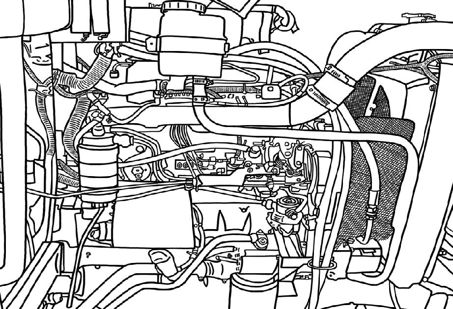
15. Disconnectthepowersteeringhoses(1).
16. Disconnecttheelectricalconnectors.Detachthe fuseboxbyunscrewingthenut(1).
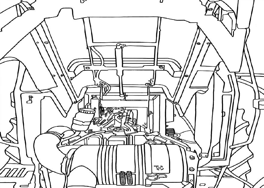
17. Disconnectthedeliveryandreturnlines(1)tothe powersteeringcylinders.
18. Removethehose(1)fromtheliftpumpsuction pipe.
TRE0606A
TRE0607A
TRE0608A
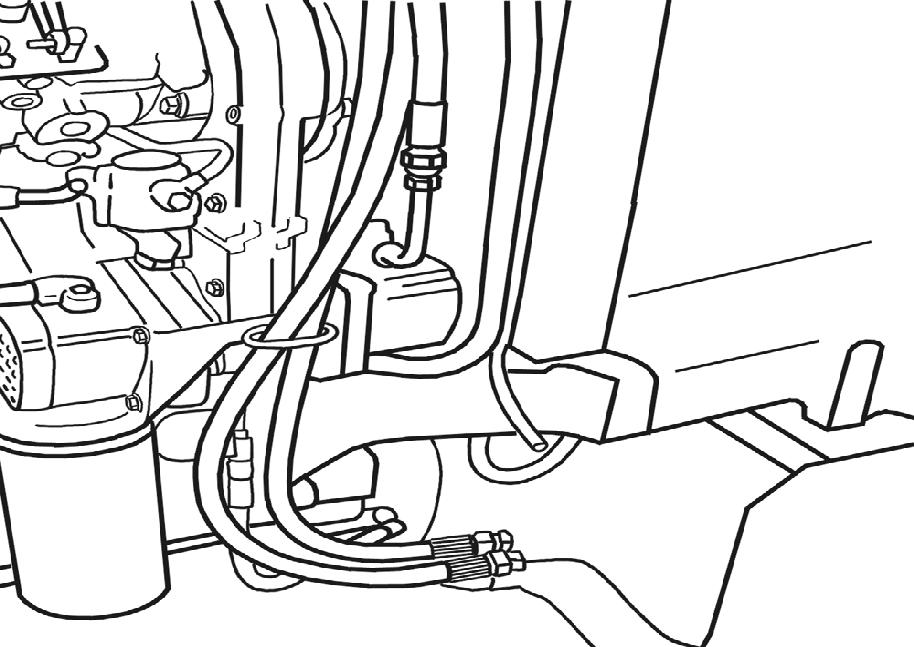
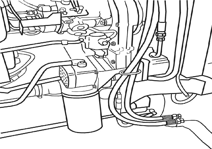
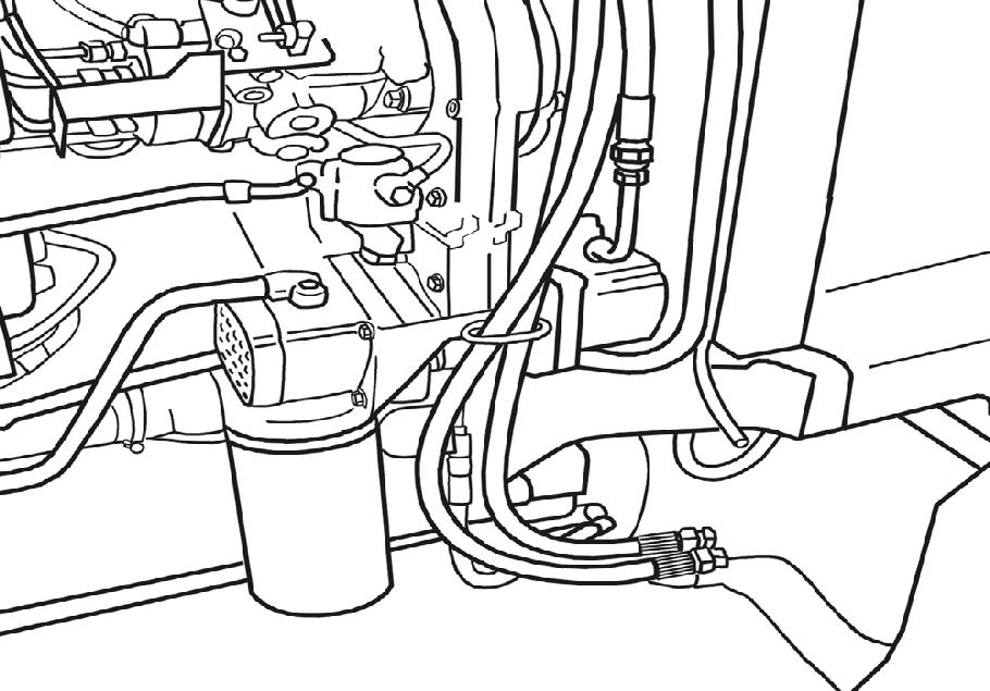
19. Detachtheliftpumpdeliverypipe(1).
20. Detachthefuelpipesfromtheinjectionpump andfuelpumpandthepipeconnectingthetank tothesedimentationfilter.
21. Removethefuelfilter(1)completewithitssupport.
TRE0609A
TRE0610A
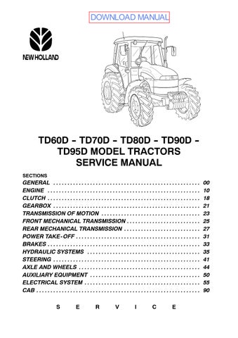
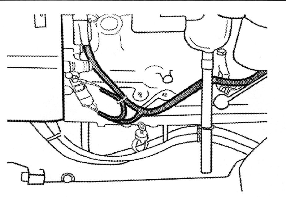
22. Removethefront,centreandrearretainingbolts fromthefrontaxledriveshaftguardandremove theguard.
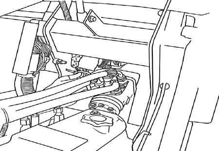
23. Removethecirclip(2)fromthefrontoftheprop shaftandslidethesleeve(1),inthedirection shownbythearrow,untilitisfreeofthesplines onthefrontaxle.
24. Removethecirclip(2)fromtherearoftheprop shaftandslidethesleeve(1),inthedirection shownbythearrow,untilitisfreeofthesplines onthecrankshaft.
25. Removethemiddlesupportbolts(1)fromthe propellershaftandremovetheshaftcomplete withsupport.
26. Withdrawthepinsecuringthedifferentiallock(1) knob,removetheknobandremovethemat(2) fromthefloor.
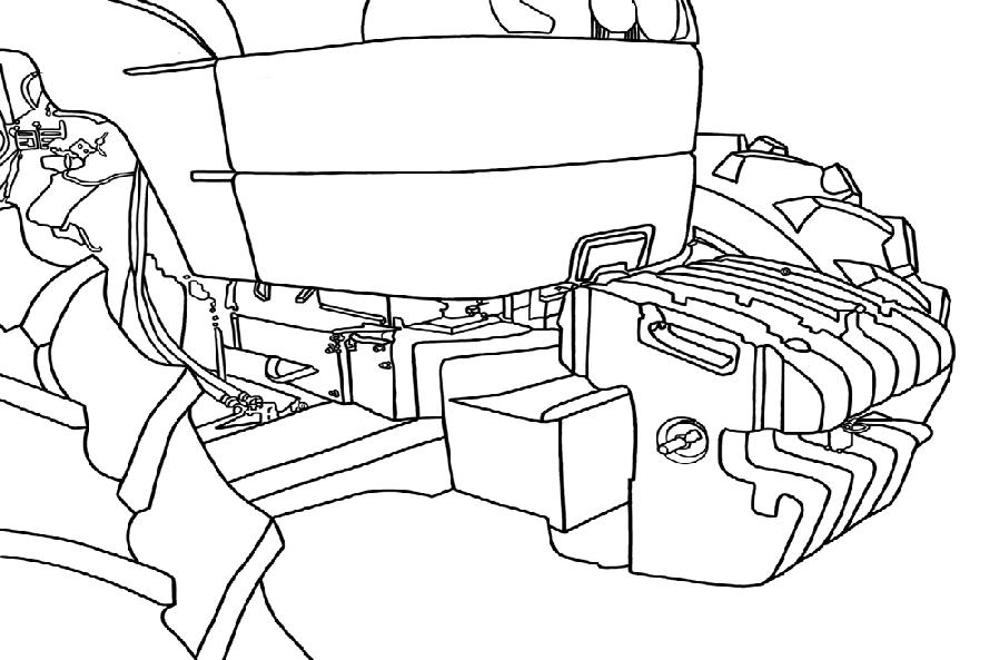
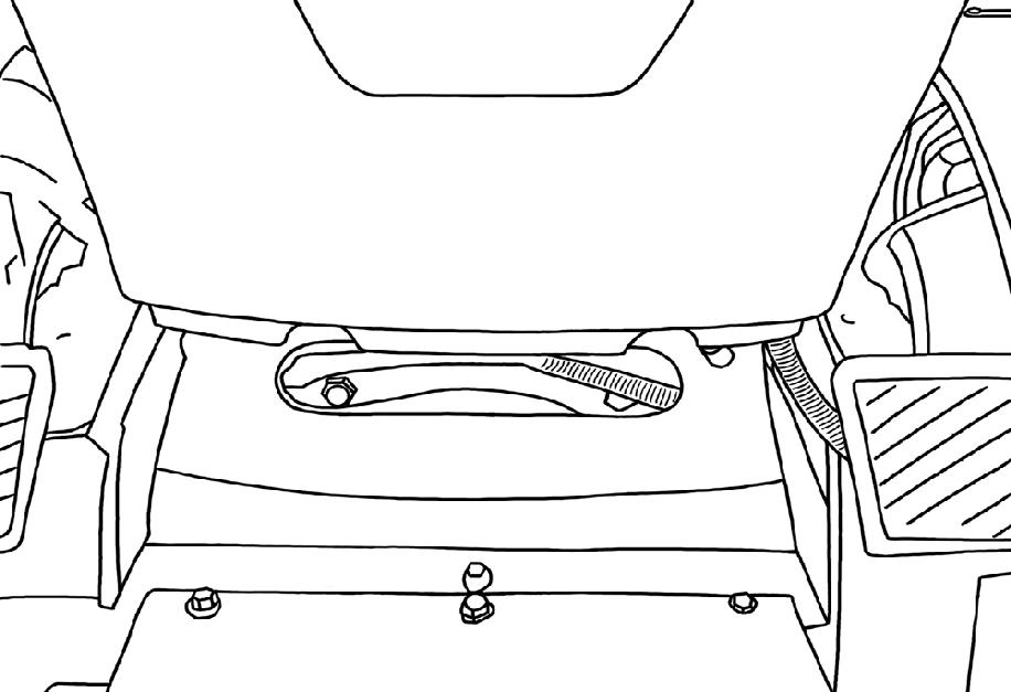
27. Unscrewthenuts(1)andtheboltssecuringthe enginetothetransmission.Accessisthrough thetwoslotsinthecabfloor.
28. Unscrewthefourlowerbolts(1)securingthe enginetothetransmission.
TRE0611A
TRE0612A
29. Positionstand 380000236 underneaththetractorandinsertawedge(1),eithersideoftheaxle, topreventtheaxlefrompivoting.
30. Insertawoodenblockbetweenthestandsand thetractor.
31. Placeafixedstand(1)underneaththedrawbar supportandapplythehandbrake.
32. Unscrewthefourremainingboltssecuringthe enginetothetransmission.
33. Separatetheenginefromthetransmission.
34. Removethespacercollar(1)betweenthe engineandthetransmissionontheTD95D model.
35. Placeafixedstand(1)underneaththefront weightsupportandchockthewheelswith woodenwedges(2).
36. Insertthepinofkit 380000612 (11”/11”clutch)or thepin 380000292 (12”/12”clutch)(1)intothe centralholeoftheclutch.Unscrewthesixbolts (2)securingtheclutchtotheflywheeland removecompleteclutchassembly.
37. Removetheradiatormountingbolt(1).
TRE0613A
38. Attachtheenginetothehoistusingan adjustablechain(1)attachedtothelifting pointsprovidedontheengine.
39. Removetheliftpump(1)completewithitsfilter byunscrewingthefourretainingbolts.
40. Disconnectallelectricalconnectorsandremove thecompletewiringharness(1).
TRE0614A
TRE0615A
41. Slackenofthehoseclampanddetachhose(1) fromtheinletmanifold.
42. Removetheleft--handsidefanguard(1).
43. Unscrewthebolts(1)securingthesilencertoits bracket.
44. Undothehoseclampanddisconnectthetop radiatorhose(1).
45. Unscrewthethreenutssecuringthesilencerto themanifoldandliftofftheentiresilencerassembly.
TRE0616A
TRE0617A
TRE0618B
TRE0613B
46. Usingthehoist,raisetheengineslightlyand positionthemoveablestand(1)underthefront axle.
47. Undothehoseclampanddisconnectthebottom radiatorhose(1).
48. Unscrewthefourbolts(2)securingtheengineto thefrontaxlesupport,andlowertheengineonto awoodenplatform.
Tore--installtheengine,proceedasfollows:
—Attachthethreehooksofanadjustablelifting chaintothethreeeyeboltsontheengine.Raise theenginefromtheplatformandpositionitin frontofthefrontaxlesupport.Jointhetwounits usingthefoursecuringbolts.
—Repositionthemoveablestandfromunderthe frontaxledifferentialhousingtoundertheengine sump,insertingasuitablyshapedblockofwood betweenthestandandthesumppan.
—Attachthetopradiatorhosetothethermostat housingandsecurewithanadjustablehose clamp.
—Connectthebottomradiatorhosetothecoolant pumpandsecureatbothendswithadjustable hoseclamps.
—Refitthefuelpump.
—Detachtheliftingchainfromtheengine.
—Connecttherigidpipefromtheaircleanertothe inletmanifoldandsecurewiththerelativeclamp.
—Reconnectallelectricalleads:thermostart glowplug,coolanttemperaturesensor,‘air filterblocked’sensor,horn,frontaxlesupport earth,enginestoponinjectionpump,leadsto thealternatorandrelay,oilpressuresensor, startermotor,fueldryerfilter.Secureallleads withplasticties.
—Fittheclutchbackonwiththeaidofkit 380000612 (11”/11”clutch)orpin 380000292 (12”/12”clutch).Fixclutchtotheengineflywheelusingthesixretainingbolts.
—Reconnecttheoildeliverypipetothe4WD controlvalve.Tightenthepipeuniononthe anti--cavitationaccumulator;fixthebracketon theleft--handsideneartheengineoilfilter.
—Cleanthedistancecollarandthematingsurfacesoftheoverdriveclutchhousing;scrape awayalltracesofoldsealingcompound.
—ApplyLOCTITEsealingcompoundtothe matingsurfacesofengineanddistancecollar. Fitthedistanceringontheenginestuds.
—ApplyLOCTITEsealingcompoundtothemating surfacesoftheoverdriveclutchhousing.
—Removethefixedstandfromunderthefront weightsupport.Removethewoodenwedgesfrom underthefrontwheels.
—Attachtheadjustableliftingchaintotheeyebolts ontheengine.
—Placewoodenwedgesundertherearwheels, checkthatthehandbrakeisfullyonandthatthe fixedandmoveablestandsarefirmlyinplace.
—Detachtheliftingchainfromtheengine.Connect thetwowiresstillattachedtothecabhandrailto thehookofthehoist.Raisethefrontpartofthe cababout6cm.
—Replaceandtightenalltheboltssecuringthe enginetotheoverdriveclutchhousing.
—Boltthebrakepipesupportbrackettotheright-handsideoftheengine.Lowerthehoistanddetachthecablesfromthecabhandrail.
—Lowerthestandsundertheenginesumpandthe clutchhousing.Removetool 380000236 andthe standfromunderthedrawbarsupport.
—Fixthecabinplacewiththetwofrontsecuring bolts.
—Connecttheinjectorleak--offpipe.Connectthe pipestotheglowplugandtothefueldryerfilter.
—Refitthefuelfiltermountingtotheengine.Connect thetwosemi--rigidpipestothemounting.
—Connecttheoilsuctionpipestothepumps; securetherubberhoseswithhoseclamps.
—Connecttherigidliftcontrolvalvesupplypipetothe relativepump,rememberingtofirstfittheO--ring.
—Securethethreepipeswiththeadjustablehose clamp.
—Connectupalltheelectricalleadstothe connectorsontheverticalsupportbracket.
—Fitthecabheaterpipeunionontheengine/ clutchdistancecollar.Connecttherubberheater hosestotheunionand,ifnecessary,restorethe gasintheair--conditioningsystemwithtool 294030.
—Connectthetwoflexiblepowersteeringpipesto theunionontheleft--handsideofthefrontaxle. Securethetwopipeswiththespecialclampand screwtheclamptothetractor.
—Fitthetachometercableandsecurethesleeve withtheretainingring.
—Fitthesilencerontotheexhaustmanifold, rememberingtoreplacethegasseal.Fixthe frontofthesilencertotheverticalsupport bracket.AttachtheflexibleDONASPINpipe.
—Attachthebonnetstaybrackettotheradiator bracket.
—Refitthe4WDpropellershaftandtheguard.
—Re--connectthethrottlecabletotheaccelerator pedal.Itmaybenecessarytoadjustthecableat theinjectionpumpleverend.
—Refittheclutchcabletotheclutchpedal.Fixthe sleevetothetravelstop.
—Replacetheplasticplugsintheholesinthecab floor.Replacethemat.
—Refitthesteeringcolumncoverpanels.
—Replacethewiremeshfanguards.
—Attachslingstothebonnetinthemannerdescribedpreviouslyintheengineremovalinstructions.Screwthebonnethingetoitsbracket.Attachthegasstrut,theelectricalleadstothe headlampsandthenremovetheslings.
—Refitthesecondarybracket(batterysupport)to theoverdriveclutchhousing.Fittherotating bracketwiththebatterytothefixedsupport.
—Refitthefrontweightsandsecurewiththelock pin.
—Refitthetoolboxsupportbracketandthenthe toolbox.
—Fillthetransmission/gearboxandpowersteeringunitwithoil.
—Filltheradiatorwithcoolant.
—Connectthebatterypositiveandnegativeleads. Replacetheplasticbatterycover.
87616423 --01--2007
WARNING
Handleallpartscarefully.Donotputyourhandsor fingersbetweenparts.
Wearsuitablesafetyclothing,safetygoggles,gloves andfootwear.
1. Removethefrontandrearretainingscrewsfrom thebonnetstaybracket(1).
2. Removethebonnetcatchsupportsideretaining bolts(1)andbackretainingbolts(2)takeoffthe bonnetcatchandthebonnetstaybracket.
3. Loosenthealternatorpivotbolt.
4. Loosenthebelttensionadjustmentbolt(1).
5. Releasethebelttensionadjustmentarmby unscrewingtheretainingnut.
6. Removethealternatorandcoolantpumpdrive belt.
7. Unscrewtheboltssecuringthefan(1)andpulley tothecoolantpump.Removethefanandpulley.
8. Unscrewtheunion(1)fromthewatersupplypipe tothecabheater.
9. Loosenthehoseclamp(1)anddetachthehose fromthecoolantpump.Removethecurvedhose andflexiblecabheaterhoses.
10. Removetheunion(1)inordertogainaccessto thepumpretainingbolt.
11. Unscrewthecoolantpumpretainingbolts(1) andremovethepump.
12. Unscrewthepumpsupportbolts(1)andthe silencersupportbolt.Removethetwosupports.
13. Fitmountingbracket(1)oftheset 380000313 to permitattachmentoftheenginetotherotary stand 380000201
14. Fitaneyebolt(1)onthefrontoftheenginein placeofthesilencersupport.
15. Raisetheenginefromthewoodenplatformand moveittotherotarystand 380000301 (2).Secureittothestandbymeansofthebracket(3) oftheset 380000313
16. Undothealternatorsupportretainingbolts(1) andremovethecompletealternatorassembly.
17. Unscrewthebolts(1)securingtheexhaust manifoldtothecylinderheadandremovethe manifold.
18. Detachthethrottlecontrollever(1)fromthe injectionpump.
19. Removethethermostathousingretainingbolts (1)andremovethethermostathousing.
20. Unscrewthehighpressurefuellineunions(1)on theinjectionpumpandremovethefuellines.
21. Unscrewthebolts(1)securingtheinletmanifold tothecylinderheadandremovethemanifold. 1
22. Unscrewtheunions(1)onthefuelsupplypump anddetachthefuellines.
23. Unscrewthenuts(1)securingtheinjectionpump tothetiminggearcase.
24. Undoscrews(1)andremovetheinjectionpump drivegearcover.