70D Excavator Repair
TECHNICAL MANUAL


TM1408 (14NOV89)

This manual is written for an experienced technician. Essential tools required in performing certain service work are identified in this manual and are recommended for use.
Live with safety: Read the eafety messages in the introduction of this manual and the cautions presented throughout the text of the manual.
This is the safety-alert symbol. When you see this symbol on the machine or in this manual, be alert to the potential for personal injury.
Technical manuals are divided in two parts: repair and diagnostics. Repair sections tell how to repair the components. Diagnostic sections help you identify the majority of routine failures quickly.
Information is organized in groups for the various components requiring service instruction. At the beginning of each group are summary listings of all applicable essential tools, service equipment and tools, other materials needed to do the job, service parts kits, specifications, wear tolerances, and torque values.
Binders, binder labels, and tab sets can be ordered by John Deere dealers direct from the John Deere Distribution Service Center.
This manual is part of a total product support program.
Fundamentals of Serv.se (FOS) Manuals cover basic theory of operation, fundamentals of troubleshooting, general maintenance, and basic type of failures and their causes. FOS Manuals are for training new personnel and for reference by experienced technicians.
Technical Manuals are concise guides for specific machines. Technical manuals are on-the-job guides containing only the vital information needed for diagnosis, analysis, testing, and repair.
Component Technical fdanuals are concise service guides for specific components. Component technical manuals are written as stand-alone manuals covering multiple machine applications.
IMPORTANT: Please remove this page and route through your service department.
This is a complete revision for TM1408, 70D Excavator.
Listed below is a brief explanation of “WHAT" was changed and "WHY” Ït WûtS Ghanged.
This manual was revised:
1. To included additional information on disassembiy and assembly of track recoil spring using ST4e2o Track Recoil Spring Disassembly and Assembly Tool, and DFT1087 Track Recoil Spring Disassembly and Assembly Guard Tool.
2. To include miscellaneous changes and updates.
SECTION I GENERAL INFORMAT\ON
Group I Safety
Group II General Specifications
Group III Torque Values
Group IV Fuels and Lubricants
Group V Inspection Procedures
SECTION O1 TRACKS
Group 0130 Track System
SECTION 02 AXLES AND SUSPENCION SYSTEM
Group 0250 Axle Shaft, Bearings, and Reduction Gears
Group 0260 Hydraulic System
SECTION 04 ENGINE
Group 0400 Removal and Installation
SECTION 0 ENGINE AUXILIARY SYSTEMS
Group 0505 Cold Weather Starting Aids
Group 051 Cooling System
Group 0515 Speed Controls
Group 052 lntahe System
Group 0530 External Exhaust Systems
Group 0560 External Fuel Supply Systems
SECTION 07 DAMPENER DRIVE (FLEX COUPLING)
Group 0752 Elements
SECTION 16 ELECTRICAL SYSTEM
Group 1671 Bakeries, Support, and Cables
Group 1672 Alternator, Regulator, and Charging System Wiring
Group 167 Wiring Harness and Switches
Group 1677 Motors and Actuators
SECTION 17 FRAME or SUPPORTING STRUCTURE
Group 1740
Frame Installation
Group 1749 Chassis Weights
SECTION 1 OPERATOR'S STATION
Group 180 Removal and Installstion
Group 1810 Operator Enclosure
Group 1821 Seat
Group 1830 Heating and Air Conditioning
SECTION 32-BULLDOZERS
Group 3200 Removal and Installation
Group 3215 Controls Linkage
Group 326 Hydraulic System
SECTION 3 EXCAVATOR
Group 3302 Buckets, Teeth, Shanks, and Sidecutters
Group 334 Frames
Group 3360 Hydraulic System
SECTION 43 SWING OR PIVOTING SYSTEM
Group 4311 Brakes
Group 4350 Mechanical Drive Elements
Group 4300 Hydraulic System
SECTION 9 DEALER FABRICATED TOOLS
Group 9900 OeaIer Fabricated Tools
Afl information, illustrations and specifications in this manual are 6ased on the latest i”nformation available at the tlme of publication. The right is reserved to make cnangas at any time without notice.
TM"408-19-1 4NOV89

GROUP I Safety
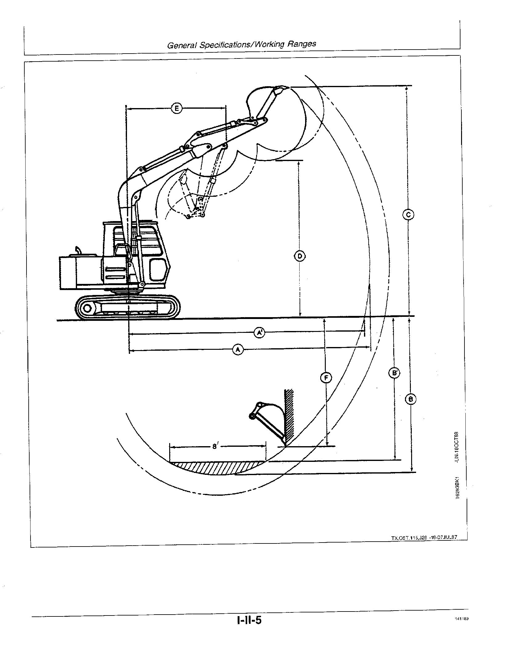
GROUP II—General Specifications
70D Specificati Drain and Refill Capacities Working Ranges Lift Capacity k
GROUP III Torque Values
Cap Screw Torque \‘alues Metric with Lett
Service Recommendations
O-Ring Boss F
Fiat Face O-Ring Seai Fittings
SAE Four Bolt Flang
GROUP IV Fuels and Lubricants
When you work around fuel, do not smoke or work near heaters or other fire hazards.
Store flammable fluids away from fire hazards. Da not incinerate or puncture pressurized containers.
Make sure machine is clean of trash, grease, and debris.
Do not store oily rags; they can ignite and burn spontaneously.
Keep sparks, lighted matches, and open flame away from the top of battery. Battery gas can explode.


Never check battery charge by placing a metal object across the posts. Use a volt-meter or hydrometer.
Do not charge a frozen battery; it may explode. Warm battery to 16°C (60°F). O53,SPARKS
Be prepared if a fire starts.
Keep a first aid kit and fire extinguisher handy.
Keep emergency numbers for doctors, ambulance service, hospital, and fire department near your telephone. DE3 F RE2 -1B-03MAR8B
Sulfuric acid in battery electrolyte is poisonous. It is strong enough to burn skin, eat holes in clothing, and cause blindness if splashed into eyes.
Avoid the hazard by:
ng batteries in a well-ventilated area.
2. Wearing eye protection and rubber gloves.
3. Avoiding breathing fumes when electrolyte is added.
4. Avoiding spilling or dripping electrolyte.
S. Use proper jump start procedure.

If you spill acid on yourself:
1. Flush your skin with water.
2. Apply baking soda or lime to help neutralize the acid.
3. Flush your eyes with water for 10 15 minutes. Get medical attention immediately.
If acid is swallowed:
1. Drink laree amounts of water or milk.
2. Then drink milk of magnesia, beaten eggs, or vegetable oil.
3. Get medical attention immediately.

Escaping fluid under pressure can penetrate the skin causing serious injury.
Avoid the hazard by relieving pressure before disconnecting hydraulic or other lines. Tighten all connections before applying pressure.

Search for leaks with a piece of cardboard. Protect hands and body from high pressure fluids.
IN an accident occurs, see a doctor immediately. Any fluid injected into the skin must be surgically removed within a few hours or gangrene may result. Doctors unfamiliar with this type of inJury may call the Deere & Company Medical Department in Moline, Illinois, or other knowledgeable medical source.
Before working on the machine:
• Lower all equipment to the ground.
• Stop the engine and remove the key.
• Disconnect the battery ground strap.
• Hang a "DO NOT OPERATE” tag in operator station.


Always lower the attachment or implement to the ground before you work on the machine. If you must work on a lifted machine or attachment, securely support the machine or attachment.
Do not support the machine on cinder blocks, hollow tiles, or props that may crumble under continuous load. Do not work under a machine that is supported solely by a jack. Follow recommended procedures in this manual.


Wear close fitting clothing and safety equipment appropriate to the job.

Prolonged exposure to loud noise can cause impairment or loss of hearing. § §


Wear a suitable hearing protective device such as earmuffs or earplugs to protect against objectionable or uncomfortable loud noises.
Tie long hair behind your head. Do not wear a necktie, scarf, loose clothing, or necklace when you work near machine tools or moving parts. If these items were to get caught, severe injury could result.
Remove rings and other jewelry to prevent electrical shorts and entanglement in moving parts.
 OSS,LOWER -19-21DEC87
Never operate the machine if an unsafe condition exists. Attach a “DO NOT OPERATE” tag to the machine.


Be sure you understand a service procedure before working on the machine.
Never lubricate or work on the machine while it is moving.
Always use two people when making checks with the engine running the operator at the controls, able to see the person doing the checking.

Keep hands away from moving pans.
Never work under a machine raised by the boom. If the machine must be raised, keep a 90 110' angle between boom and arm.
Support the machine in the raised position by placing blocks or jackstands under machine.
Do not work under a raised bucket. Lower bucket to ground or onto blocks.
Disconnect battery ground cable ( ) before welding on the machine or making adjustments on the engine or electrical system.

Engine exhaust fumes can cause sickness or death. If it is necessary to run an engine in an enclosed area, remove the exhaust fumes from the area with an exhausl pipe extension.
If you do not have an exhaust pipe extension, open the doors and get outside air into the area.
TX,02T,05,CB3 -19-1BMARBZIlluminate your work area adequately but safely. Use a portable safety light for working inside or under the machine. Make sure the bulb is enclosed by a wire cage. The hot filament of an accidentally broken bulb can ignite spilled fuel or oil.
Catch draining fuel, oil, or other fluids in suitable containers. Do not use food or beverage containers that may mislead someone into drinking from them. Wipe up spills at once.
Replace missing or damaged safety signs. See the machine operator's manual for correct safety sign placement.
Liftin9 heavy components incorrectly san cause severe injury or machine damage.
Follow recommended procedure for removal and installation of components in the manual.


 OT3,LIGH+ -1.^-23FEB8B
Safety/Safefy

Avoid breathing dust that may be generated when handling components containing asbestos fibers. Inhaled asbestos fibers may cause lung cancer.
Components in John Deere products that may contain asbestos fibers are brake pads, brake band and lining assemblies, clutch plates, and some gaskets. The asbestos used in these components is usually found in a resin or sealed in some way. Normal handling is not hazardous as long as airborne dust containing asbestos is not generated.
Avoid creating dust. Never use compressed air for cleaning. Avoid brushing or grinding of asbestos containing materials. When servicing, wear an approved respirator. A special vacuum cleaner is recommended to clean asbestos. If not available, wet the asbestos containing materials with a mist of oil or water.

Keep bystanders away from the area.
BeJore starting a job:
• Clean work area and machine.
- Make sure you have all necessary tools to do your job.
• Have the right parts on hand.
• Read all instructions thoroughly; do not attempt shortcuts.
Use tools appropriate to the work. Makeshift tools, parts, and procedures wil! not make good repairs.
Use pneumatic and electric lools only to loosen threaded parts and fasteners. Never use such tools to tighten fasteners, especially on light alloy parts.
Use only replacement parts meeting John Deere specifications.

Improperly disposing of fluids can harm the environment and ecology. Before draining any fluids, find out the proper way to dispose of waste from your local environmental agency.
Avoid pouring oil into the ground, down a drain, or into a stream, pond, or lake. Observe relevant environmental protection regulations when disposing of oil, fuel, coolant, brake fluid, filters, batteries, and other harmful waste.

Before returning machine to customer, make sure machine is functioning properly, especially the safety systems. Install all guards and shields.
 os9,LivE -1s-o3JANa8

80 kg (175 lb) operator, and standard
I-II-1 ..
Engine: John Deere 4-239D
Hydraulic System: Open center. Two variable-displacement axial-piston pumps and one control valves (5 and 4 spool sections) provide independent and combined operation of all functions. The 5-spool control valve section has one spool for optional offset boom or an auxiliary attachment.
‘Maximum boom outset: I.!5 m (S It 9 in.1
””Maxiinum digging depth will be less in applications where oflsei boam interferes with edpe of trench.
Boom: Standard
Arm: 1.62 m (5 ft 4 in.)
Dozer Blade: No
LIFTING OVER FRONT OR REAR
“ Hydraulic limited capacity
NOTE. iafinps af Liuckel lifl hook; machine equipped with so mm (1s in.) shoes, 0.ñ’ m* (0,31 yd^) PCSA heaped bucket, and standard counterweight situated on firm, level, unifomt supporting surface. Lifting capeci”fy daes not exceed 7E% of tipping load or 87% of full hydraulic capacity.
Boom: Standard Arm: 1.62 m (5 ft 4 in.)
Dozer Blade: Yes
'Hydraulic limited capacity
NOTE.- Ratings at bucket iift hook,’ machine equipped with 450 mm (JO in.) shoes, 0.24 (0.31 yet) PCfiA heaped bucket, and standard counterweight; situated on firm, level, uniform supporlinp surface. Liflinp capacity does not exceed 7'5 • of tipping load or 87% of full hydraulic capacity.
Boom: Standard
Arm: 2.12 m (6 ft 11 in.)
Dozer Blade: No
LIFTING OVER FRONT OR REAR
NOTE.- Ratings at bucket lift haok, machine equipped with 450 mm (18 in.) shoes, 0.24 (0.31 yd*) PCSA heaped bucket, and standard cauntem'eighf; situated an fi'rm, level, uniform suppariiiig su/Yace. Lifting capacity does not exceed 75% af tipping laad or 87% of full hydraulic