Diesel engine exhaust and some of its constituents are known to the State of California to cause cancer, birth defects, and other reproductive harm.
California
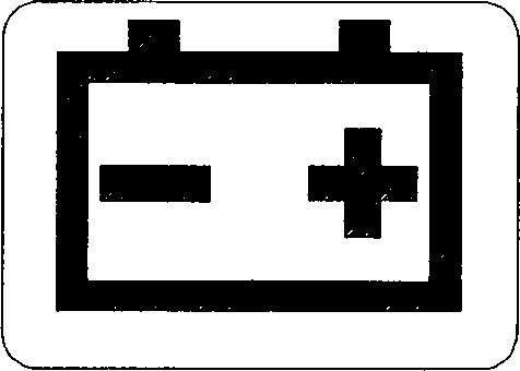
Proposition 65 Warning
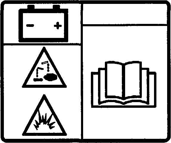
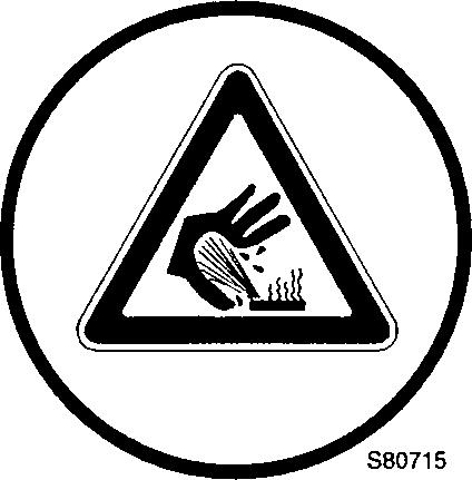
Battery posts, terminals and other related accessories contain lead and lead compounds, chemicals known to the State of California to cause cancer and other reproductive harm. Wash hands after handling.
Foreword
This Operator Manual is intended as a guide for the correct use and maintenance of the machine. Therefore, study it carefully before starting and operating the machine, or before carrying out any preventive maintenance.
Keep the manual in the intended place in the cab so that it is always at hand. Replace it immediately, if it is lost.
The manual describes the applications for which the machine primarily is intended and is written to apply to all markets. We therefore ask you to disregard the sections which are not applicable to your machine or to the work for which you use your machine.
Many hours are spent on design and production to make a machine that is as efficient and safe as possible. The accidents which occur in spite of this, are mostly caused by the human factor. A safety conscious person and a well maintained machine make a safe, efficient and profitable combination. Therefore, read the safety instructions and follow them.
NOTE :
This manual has been adapted to cover all markets. Disregard optional or special equipment included for various markets, which are not applicable to your machine.
We continually strive to improve our products and to make them more efficient through changes to their design. We retain the right to make these improvements on products which have already been delivered.
We also retain the right to change data and equipment, as well as instructions for service and maintenance without prior notice.
Safety regulations
It is the operator obligation to know and follow the applicable national and local safety regulations. The safety instructions in this manual only apply to cases when there are no national or local regulations.
WARNING!
The symbol above appears at various points in the manual together with a warning text. It means: Warning, be alert! Your safety is involved! It is the obligation of the operator to make sure that all warning decals are in place on the machine and that they are readable. Accidents may otherwise occur.
Get to know the capacity and limits of your machine!
Contents
Presentation
Instruments and controls
Operating instructions
Safety when servicing
Service and maintenance
Specifications
Alphabetical index
This symbol, which is shown at various places in the Operator's Manual together with a warning statement, means:
WARNING!
Warning, be alert! Your safety is involved!
To ignore the risks may lead to an accident, serious injuries.
It is the obligation of the operator to make sure that all warning decals are in place on the machine and that they are readable. Accidents may otherwise occur.
Get to know the capacity and limits of your machine!
Handling and maintenance of the machine
Volvo Construction Equipment is responsible only if: the machine has been used in a correct way and been maintained in accordance with the instructions contained in the Operator's Manual and Service Manuals.
prescribed service and prescribed inspections have been carried out at the stated points in time.
the recommended lubricants according to the manual have been used.
fitted security seals are unbroken or that adjustments and refitting of security seals has been carried out by an authorized dealer workshop.
all modifications and repairs performed, and methods used, have been prescribed by Volvo.
only Volvo genuine spare parts/accessories, or genuine spare parts/accessories which meet Volvo's requirements, have been used.
WARNING!
An operator of an excavator must have sufficient knowledge and instructions before he/she operates the machine.
An untrained operator can cause serious injuries.
Never use an excavator which has no Operator's Manual.
Understand the warning plates and symbols on the machine and its operator instructions before you begin to use the machine.
Communication equipment, installation
IMPORTANT!
All installation of optional electronic communication equipment must be performed by trained professionals and in accordance with Volvo Construction Equipment instructions applicable to the specified machine.
Protection from electromagnetic interference
This machine has been tested in accordance with EU directive 89/ 336/EEC governing electromagnetic interference. It is therefore very important that all non-approved electronic accessories, such as communication equipment, should be tested before installation and use, since they can cause interference to the electronic systems of the machine.
Mobile telephones
To obtain the best functionality, mobile telephones should be permanently installed in the electrical system of the excavator, with a permanently antenna fixed on the cab, installed as advised by the manufacturer. If a portable mobile telephone is used, note that this can constantly transmit information to its base station, even when the telephone is not used. For this reason, it should not be located beside electronic equipment in the machine, such as directly on a control panel etc.
Guidelines
The following guidelines must befollowed during installation: The antenna placement must be chosen to give good adaptation to the surroundings.
The antenna cable must be of the coaxial type. Be careful to ensure that the cable is undamaged, that the sheath and braid are not split at the ends, the braid covers the connector ferrules and has good galvanic contact with them.
The mating surface between the antenna mounting bracket and the bodywork must have clean metal surfaces, with all dirt and oxide removed. Protect the mating surfaces against corrosion after installation, to maintain good galvanic contact.
Remember to separate interfering and interfered cables physically. Interfering cables consist of the communication equipment's supply cables and antenna cable. Interfered cables are those which are connected to electronic devices in the machine. Install the cables as close as possible to earthed (grounded) sheet metal surfaces, since the sheet metal has a shielding effect.
4 Communication equipment, installation
Presentation
General
Intended use
The machine is intended to be used in the way described in this manual. If the machine is used in another way or in potentially dangerous environments, e.g. explosive atmosphere or areas with dust containing asbestos, special safety regulations must be followed and the machine be equipped for such use.
Contact the manufacturer/dealer for further information.
Engine
The engine is a straight six cylinder, four stroke, direct injection diesel with 5.7 liter cylinder volume, turbocharged, intorcooled and electronically controlled fuel injection by EMS (Engine Management System), Volvo engine D6DEAE2
Electrical system
The electrical system consists of engine starting system, charging system, machine monitoring system, engine/pump control system and air conditioning system.
Engine speed is controlled by a rotary switch that incrementally changes rpm, and an auto idle system that automatically engages low idle when the machine is not operated for 5 seconds or more. Engine condition can be checked via the V-ECU (Vehicle Electronic Control Unit) by the data connection between EMS (Engine Management System) and V-ECU.
IECU (Instrument Electronic Control Unit) consists of central warning lamp, two analog gauges, 21 indicators, MCD (Message Center Display), and four push buttons. IECU is installed inside the cab and displays vehicle information for the operator.
Hydraulic pump
The hydraulic pump assembly consists of two pumps connected by a splined coupling. The two pumps are driven simultaneously as the engine rotation is transmitted to the front drive shaft.
The pump consists of rotary group, swash plate group and valve block group.
The displacement of the pump is controlled by the regulator, and engine output power is effectively utilized by the proportional solenoid valve.
Main control valve
The control valve consists of a four spool block, a three spool block connected by screws. They contain six main spools for digging units, three spools for conflux and straight travel, a spool for the option unit, a main relief valve, port relief valves, holding valves and check valves. These are remotely controlled by the servo hydraulic system.
Track motor and gearbox
The track motor is a variable swash, axial piston design that includes the brake valve assembly and parking brake. The rear flange contains the counterbalance valve, check valves, crossover relief valves and displacement changeover valve.
The gearbox composed of sun gear, planetary gear, pinion gear and housing.
Swing motor and gearbox
The rotary group consists of cylinder block and nine pistons assembles located in the cylinder. Piston assemblies are guided by return plate and spring so they slide smoothly on the swash plate.
The cover section has a relief valve for cushioning and an anti-cavitation valve to prevent cavitation.
Gearbox is composed of sun gear, planetary gear, pinion gear and housing. Power supplied to the output shaft of the swing motor reduces the motor speed through the sun gear and planetary gear and the high torque is transmitted to the pinion gear.
Cab
The cab has a heating and ventilation system with defrosting from front and rear windows. Air conditioning is available as an option. The cab have two emergency exits, the door and the rear window.
Anti-theft device (optional equipment)
An installed anti-theft device makes it more difficult to steal the machine. Volvo CE supplies anti-theft devices as optional equipment. If your machine is not yet equipped with one, check the possibilities of having such a device installed by your dealer.
FOPS and FOG
The cab is approved as a protective cab according to FOPS and FOG standards, see Protection f'rom falling or scattering material on page 99. FOPS is an abbreviation of Falling Object Protective Structure (roof protection) and FOG is an abbreviation of Falling Object Guard.
Never carry out any unauthorized alterations to the cab, e.g. lowering the roof height, drilling, welding on brackets for fire extinguisher, radio aerial or other equipment, without first having discussed the alteration with personnel at the Volvo Engineering Department. This department will decide whether the alteration may cause the approval to become void.
It is important that all parties concerned are ware of these regulations.
Modifications
Modifications to this machine including the use of unauthorized attachments, accessories, assemblies or parts may affect the integrity of the machine and/or the ability of the machine to perform as designed. Persons or organizations making unapproved modifications assume all liability arising from or related to the modification, including any adverse affect on the machine.
No modifications of any kind should bemade tothis product unless the specific modification has been officially approved in writing by Volvo Construction Equipment. Volvo Construction Equipment reserves the right to reject any and all warranty claims which arise from or are related to unauthorized modifications.
Modifications are officially approved if at least one of the following conditions is met:
1 The attachment, accessory, assembly or part is manufactured or distributed by Volvo Construction Equipment and installed in a factory approved manner as described in the publications available from Volvo Construction Equipment; or
2 The modification has been approved in writing by the Product Line Engineering Department of Volvo Construction Equipment.
CE marking and Declaration of Conformity
NOTE : Applies only to machines marketed within the EU/EEA. This machine is CE marked. This means that, when delivered to the customer, the machine meets the applicable “Essential Health and Safety Requirements”, according to the EU Machine Safety Directive. Any person carrying out an alteration that affects the safety of the machine, is responsible for the consequences. The machine is supplied together with a Declaration of Conformity with the EU Machine Safety Directive. The documentation is a valuable document, which should be kept safe and always be kept in the machine.
If the machine is used for purposes or with other attachments than described in this manual, safety must at all times and in each separate case be maintained. The person carrying out such action is also responsible for the action which, in some cases, may require a new CE marking and the issue of a new EU Declaration of Conformity.
Volvo CE is only responsible for a machine which is used with approved equipment and spare parts specified by Volvo CE.
Volvo Construction E uinmento
EU EMC Directive
The electronic equipment of the machine may in some cases cause interference to other electronic equipment, or suffer from external electromagnetic interference, which may constitute safety risks.
The EU EMC directive on“Electromagnetic compatibility”, 89 / 336 / EEC, provides general description of what demands can be made on the machine out of a safety point of view, where permitted limits have been determined and given according to international standards.
A machine or device which meets the requirements should be CE marked. Our machines have been tested particularly for electromagnetic interference. The CE marking of the machine and the declaration of conformity also cover the EMC directive.
If other electronic equipment is fitted to this machine, the equipment must be CE marked and tested on the machine with regard to electromagnetic interference.
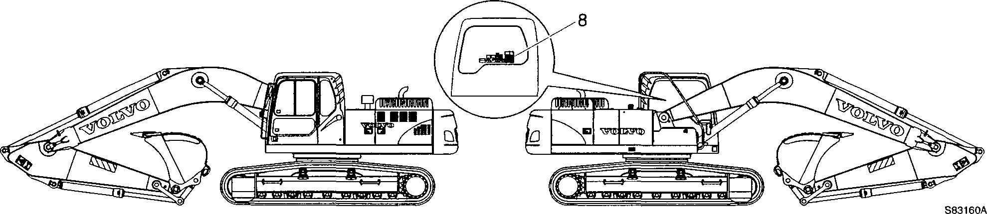
Plates and decals
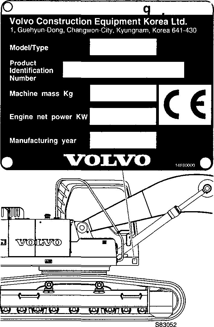
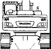
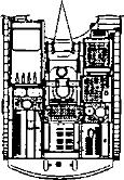
Product plates
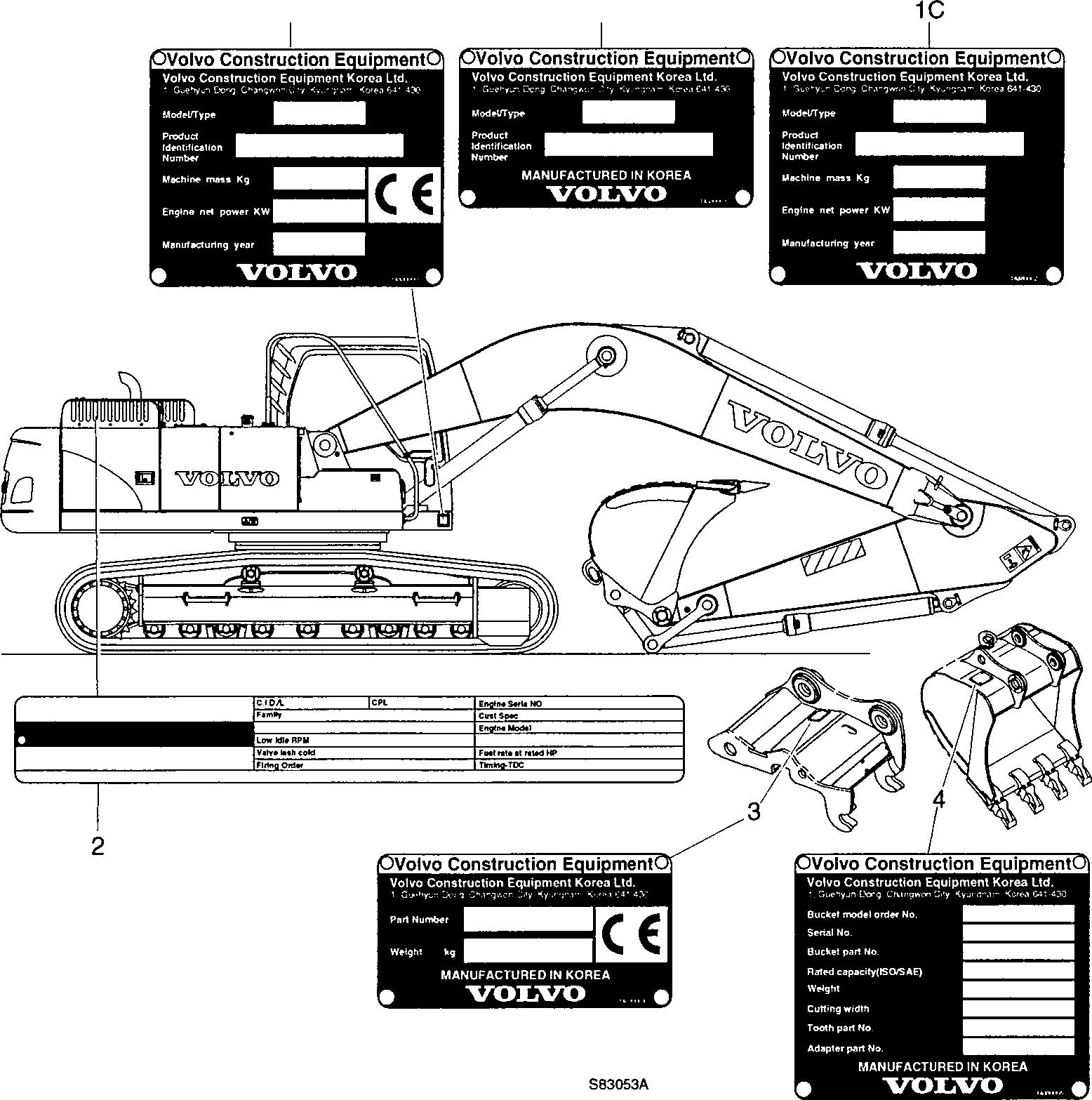
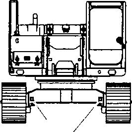
This illustration and text below show which product plates are found on the machine.
When ordering spare parts and when making enquires by telephone or correspondence, the model designation and Product Identification Number (PIN) should be stated.
Plates and decals
1 Product plate with Product Identification Number, PIN for the complete machine (shows the model, serial numbers, machine weight, engine output and when applicable CE approval). The plate is positioned on the right side of the upper frame.
1A: Product plate, version for EU market
1B: Product plate, version for North America, International market
1C: Product plate, version for Middle East market
2 The engine type designation, part and serial numbers are stamped into both sides of the cylinder block.
3 The quickfit nameplate is attached on the outside of the quickfit. (shows part number and weight)
4 The bucket nameplate is attached on the top of the bucket. (shows the bucket model order Number, serial number, bucket part number, rated capacity, weight, cutting width, tooth part number and adapter part number)
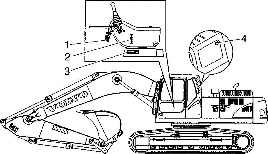
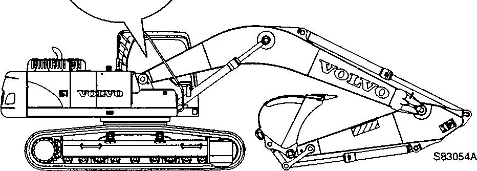
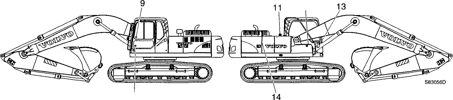
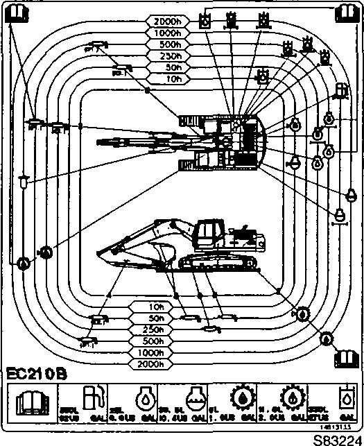
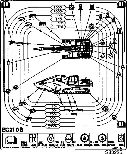
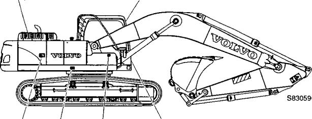
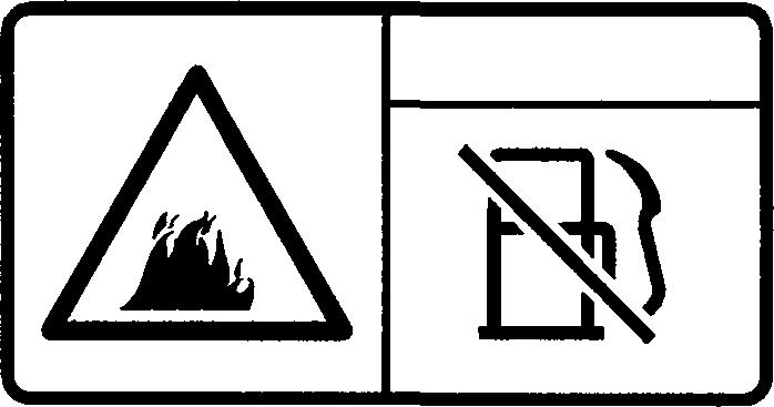
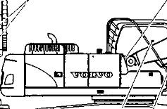
Information and warning plates
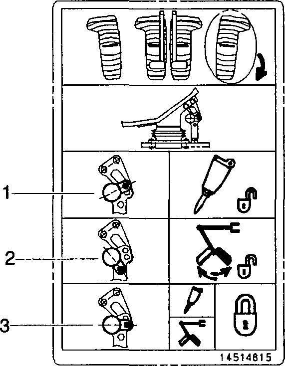
The following depicts various warning and information texts that may be affixed to the machine and their mounting location. The operator must know and pay attention to the warning and safety information on each decal and plate. Decals / plates that are lost, damaged, illegible, painted over or not clearly visible must be replaced immediately.
The part number (order number) of the respective plates / decals can be found in the Parts Catalogue.
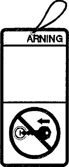
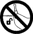
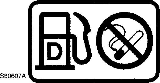
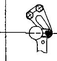
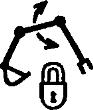
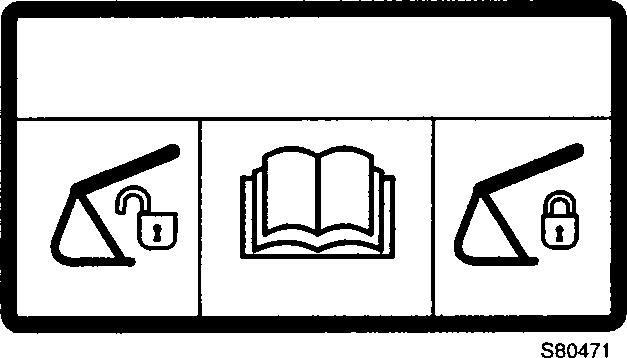
1 Do not start the engine
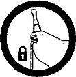
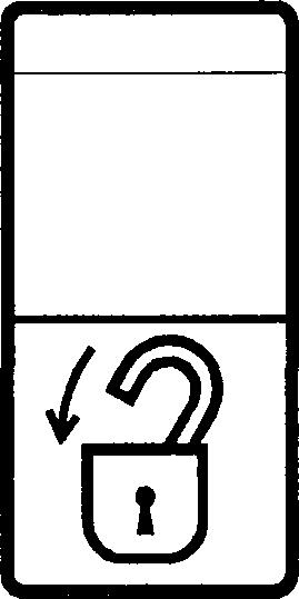
2 Safety locking
See Sa/'efy locking system on page 81.
WARNING
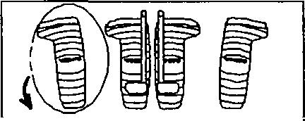
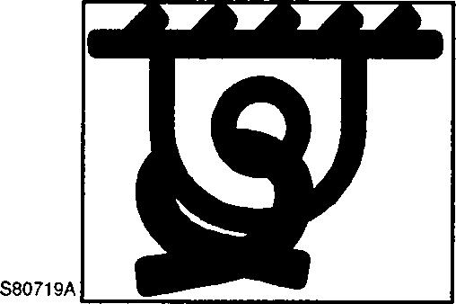
3 Do not unscrew the recoil spring
See inspecting and adjusting fhe frack s/ack on page 197.
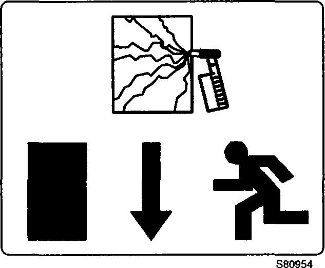
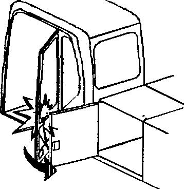
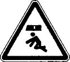
4 Emergency exit
See 7he emergency hammer (B) should 6e used in an emergency sift/afions. on page 86.
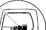
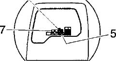
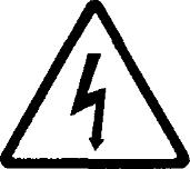
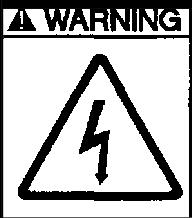
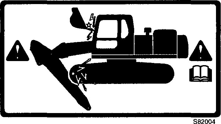
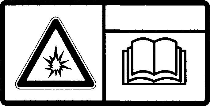
5 Warning, high voltage
See Never approach a high v'o/fage wire on page 98.
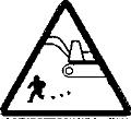
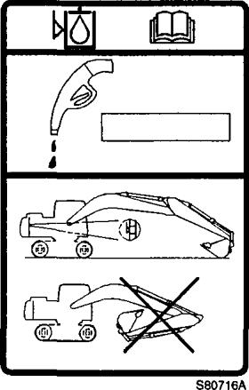
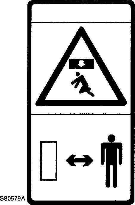
6 Warning when operating the optional attachment
If the machine is equipped with an adjustable boom or quickfit bucket, the digging arm with its boom fully retracted can damage the operator cab.
WARNING!
If the machine is equipped with any other attachments (quickfit, hammer, large bucket,...), that may damage the operator cab and other structure.
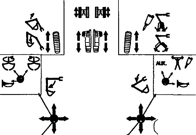
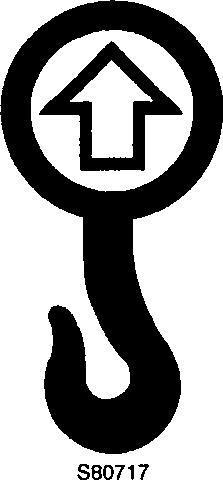
7 Operating optional attachments
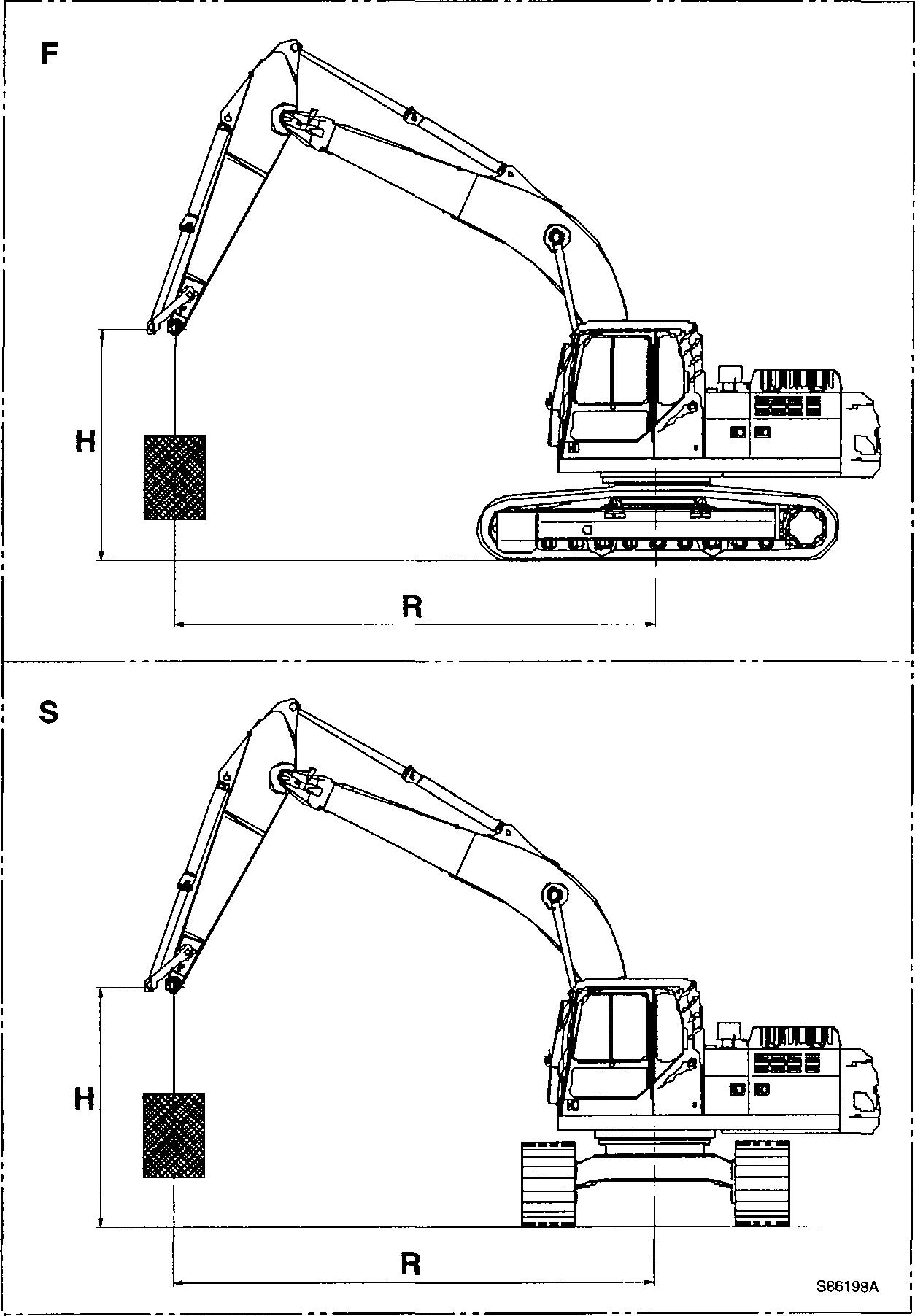
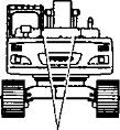
8 Lifting capacity table
F : Lifting capacity over the front or rear of the machine
S : Lifting capacity over the side of the machine
H : Height
R : Reach
MR : Maximum reach
Long Crawler (LC)
Counterweight = 9259 lb (4200 kg)
Boom = 18 h 3 in (5.57 m)
Arm = 8 ft 2 in without bucket
Shoe = 600 mm (24 in)
NOTE :
1. The above loads are in compliance with SAE and ISO Hydraulic Excavator Lift Capacity Standards.
2.They do notexceed 87% of hydraulic lifting capacity or 75% of tipping load.
3.Rated loads marked with an asterisk( ) are limited by hydraulic capacity rather than tipping load.
S86604
Plates and decals
Long Crawler (LC)
Counterweight = 9259 lb (4200 kg)
Boom = 18 ft 3 in (5.57 m)
Arm = 9 ft 6 in without bucket
Shoe = 600 mm (24 in)
NOTE :
1. The above loads are in compliance with SAE and ISO Hydraulic Excavator Lift Capacity Standards.
2. They do not exceed 87% of hydraulic lifting capacity or 75% of tipping load.
3. Rated loads marked with an asterisk( ) are limited by hydraulic capacity rather than tipping load.
Long Crawler (LC)
Counterweight = 9259 lb (4200 kg)
Boom = 18 ft 3 in (5.57 m)
Arm = 12 ft 1 in without bucket
Shoe = 600 mm (24 in)
NOTE :
1. The above loads are in compliance with SAE and ISO Hydraulic Excavator Lift Capacity Standards.
2.They do not exceed 87% of hydraulic lifting capacity or 75% of tipping load.
3. Rated loads marked with an asterisk( ) are limited by hydraulic capacity rather than tipping load.
Plates and decals
Long Crawler (LC)
Counterweight = 9259 lb (4200 kg)
Boom = 18 ft 8 in (5.7 m)
Arm = 8 ft 2 in without bucket
Shoe = 600 mm (24 in)
1. The above loads are in compliance with SAE and ISO Hydraulic Excavator Lift Capacity Standards.
2.They do not exceed 87% of hydraulic lihing capacity or 75% of tipping load.
3. Rated loads marked with an asterisk( ) are limited by hy’ draulic capacity rather than tipping load.
Long Cramer (LC)
Counterweight = 9259 lb (4200 kg)
Boom = 18 ft 8 in (5.7 m)
Arm = 9 ft 6 in without bucket
Shoe = 600 mm (24 in)
NOTE
1. The above loads are in compliance with SAE and ISO Hydraulic Excavator Lih Capacity Standards.
2.They do not exceed 87% of hydraulic lifting capacity or 75% of tipping load.
3. Rated loads marked with an asterisk( * ) are limited by hydraulic capacity rather than tipping load.
Plates and decals
Long Crawled (LC)
Counterweight = 9259 lb (4200 kg)
Boom = 18 ft 8 in (5.7 m)
Arm = 12 ft 1 in without bucket
Shoe = 600 mm (24 in)
NOTE :
1. The above loads are in compliance with SAE and ISO Hydraulic Excavator Lift Capacity Standards.
2. They do not exceed 87% of hydraulic lihing capacity or 75% of tipping load.
3. Rated loads marked with an asterisk( ) are limited by hydraulic capacity rather than tipping load.
Narrow Narrow LongCrawler (NNLC)
Counterweight = 10582 lb (4800 kg)
Boom = 18 ft 2 in (5.57 m)
Arm = 9 ft 6 in without bucket
Shoe = 500 mm (20 in)
S86610
1. The above loads are in compliance with SAE and ISO Hydraulic Excavator Lift Capacity Standards.