Product: TRACK-TYPE TRACTOR
Model: D6K2 TRACK-TYPE TRACTOR EL7
Configuration: D6K2 LGP, XL TRACK-TYPE TRACTOR
Disassembly and Assembly D6K Track Type Tractor Power Train
Download Service Repair Manual
Final Drive and Sprocket - Disassemble
SMCS - 4050-015; 4164-015
Disassembly Procedure
Start By:
a. Remove the final drive and brake.
b. Remove the track brake.
When you are using hydraulic cylinders and puller studs, always ensure that the rated capacity of the puller stud meets or exceeds the rated capacity of the hydraulic cylinder. If the puller stud does not meet or exceed the rated capacity of the hydraulic cylinder, a sudden failure of the puller stud could occur. The sudden failure of the puller stud could result in personal injury or death.
1. Drain the final drive oil. Refer to Operation and Maintenance Manual, "Final Drive OilChange" for the correct draining procedure.
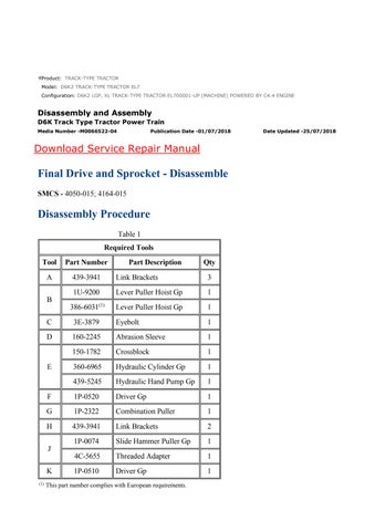
2. Attach Tooling (A), Tooling (B), and a suitable lifting device to final drive (1). The weight of final drive (1) is approximately 590 kg (1300 lb). Position final drive (1) onto suitable cribbing.
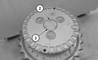
Illustration 2
g03039916
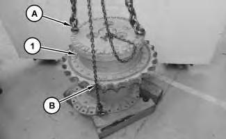
3. Remove bolts (2), cover (1), and the O-ring seal.
Illustration 3
g03040636
4. Use Tooling (C) to remove sun gear shaft assembly (4).
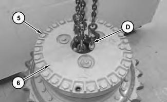
Illustration 4
g03041498
5. Attach Tooling (D) and a suitable lifting device to planetary assembly (6). The weight of planetary assembly (6) is approximately 109 kg (240 lb). Remove bolts (5) and planetary assembly (6).
5
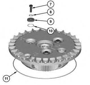
6. Remove O-ring seal (11).
7. Remove bolt (7), washer (8), retainer (9), and O-ring seal (10). Repeat for the remaining planetary gears.

6
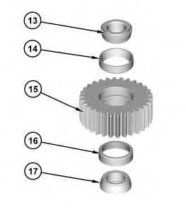
Illustration 7
g03041776
8. Use a suitable press to remove shaft (12). Remove shaft (12), bearing cone (13), planetary gear (15), and bearing cone (17) from the planetary carrier. Remove bearing cup (14) and bearing cup (16) from planetary gear (15). Repeat for the remaining planetary gears.
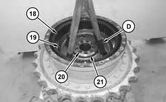
Illustration 8
g03042099
9. Attach Tooling (D) and a suitable lifting device to ring gear (18) and hub (19). The combined weight of ring gear (18) and hub (19) is approximately 40 kg (88 lb). Remove bolts (20) and retainer plate (21). Remove ring gear (18) and hub (19) as a unit.
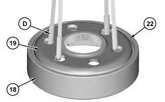
Illustration 9
g03042177
10. Attach Tooling (D) and a suitable lifting device to hub (19). The weight of hub (19) is approximately 18 kg (40 lb). Remove retaining ring (22). Remove hub (19) from ring gear (18).
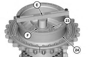
Illustration 10
g03042296
11. Attach Tooling (E) and Tooling (F) to separate bearing cone (23) and sprocket hub (24).
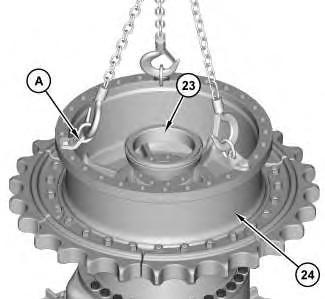
Illustration 11 g03043624
12. Remove bearing cone (23).
13. Attach Tooling (A) and a suitable lifting device to sprocket hub (24). The combined weight of sprocket hub (24) and the sprocket segments is approximately 186 kg (410 lb). Remove sprocket hub (24) and the sprocket segments as a unit.
12
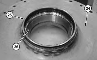
14. Remove Duo-Cone seal (25) and bearing cups (26) from sprocket hub (24). Refer to Special Instruction, SEHS8364, "Assembly and Installation of Conventional Duo-Cone Seals" for installation instructions.
13
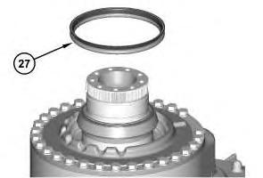
15. Remove Duo-Cone seal (27). Refer to Special Instruction, SEHS8364, "Assembly and Installation of Conventional Duo-Cone Seals" for installation instructions.
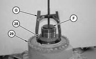
Illustration 14
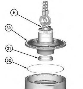
Illustration 15
g03043839
16. Use Tooling (G) and Tooling (F) to remove bearing cone (28).
17. Attach Tooling (H) and a suitable lifting device to spindle (30). The weight of spindle (30) is approximately 127 kg (280 lb). Remove bolts (29), spindle (30), and O-ring seal (32).
18. Remove bearing outer race (31) from spindle (30).
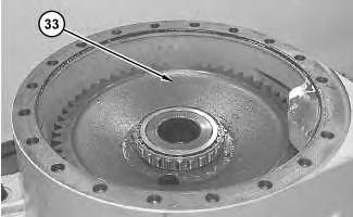
Illustration 16
19. Remove bull gear (33).
g03043841
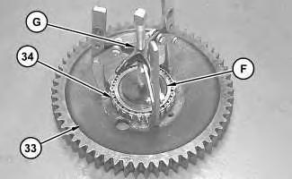
Illustration 17
g03043842
20. Use Tooling (G) and Tooling (F) to remove inner bearing (34) from bull gear (33).
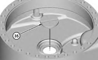
Illustration 18
21. Remove thrust button (35).
g03043844