
Models
322L EXCAVATOR

Previous Screen
Product: EXCAVATOR
Model: 322 L EXCAVATOR 9RL


Configuration: 322L EXCAVATOR 9RL00001-UP (MACHINE) POWERED BY 3116 ENGINE
Disassembly and Assembly
446 and 446B Backhoe Loaders, Lexion 450 Combine, 3114 and 3116 Engines, IT18F Integrated Toolcarrier, D6M Track-Type Tractor and 928F, 950F and 950G Wheel Loaders
Media Number -SENR3611-18
-27/05/2009
Governor - Remove
SMCS - 1264-011
Removal Procedure
Table 1
Required Tools
Tool
A 136-4149 Governor Pliers(1) 1 (1) This tool is part of the 128-8822 Fuel System and Governor Tool Group.
Start By:
a. Remove the fuel shutoff solenoid. Refer to Disassembly and Assembly, "Fuel Shutoff Solenoid - Remove and Install".
NOTICE
Care must be taken to ensure that fluids are contained during performance of inspection, maintenance, testing, adjusting, and repair of the product. Be prepared to collect the fluid with suitable containers before opening any compartment or disassembling any component containing fluids.
Refer to Special Publication, NENG2500, "Dealer Service Tool Catalog" for tools and supplies suitable to collect and contain fluids on Cat products.
i01928381
Dispose of all fluids according to local regulations and mandates.
1
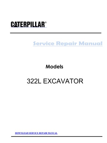
1. Disconnect the governor control cable.
2. Remove oil tube assembly (1). Remove tube assembly (2) and tube assembly for fuel ratio control (3), if equipped. Plug and cap all connections.
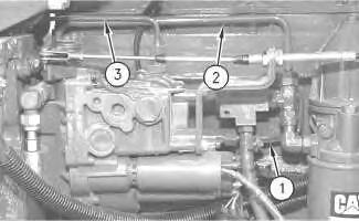
3. Remove clip (4).
Illustration
g00613041
Illustration 2
g00613071
Illustration 3
g00655975
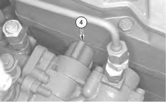
4. Use Tooling (A) to slide tube assembly (5) into the cylinder head.
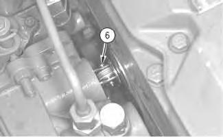
Illustration 4
g00613149
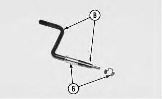
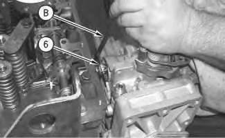
5. Remove the clip and use Tooling (A) to remove the clevis pin (6).
Note: Clevis pin (6) must stay with the governor in order to be adjusted.
5
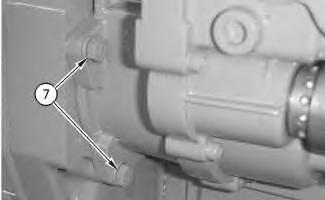
6. Remove bolts (7) and the washers that hold the governor in position.
6
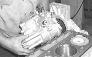
7. Remove the governor from the engine.
7
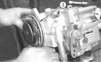
8. Remove O-ring seal (3) on the governor.
Illustration
g00673182
Illustration
g00673180
9. Remove the O-ring seal and tube assembly (5) from the cylinder head.
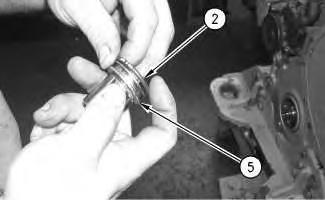
Illustration 9
g00672733
10. Remove O-ring seal (2) on the tube assembly (5).
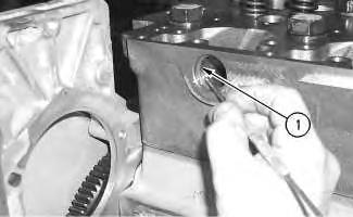
Illustration 10
g00673178
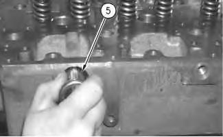
11. Remove O-ring seal (1) from the cylinder head.
Note: For more information on the governor, refer to Service Manual, SENR6454, "3114, 3116, & 3126 Engine Governors". The Service Manual, SENR6454 requires the use of a 1U-7326 Governor Calibration Bench. For information on reusability of components in the governor, refer to Guideline For Reusable Parts And Salvage Operations, SEBF8434, "3100 Governor Inspection and General Information for Mechanical Governor Groups Used in 3114, 3116, and 3126 Engines Equipped with Mechanical Unit Injectors (MUI)".
Copyright 1993 - 2019 Caterpillar Inc. All Rights Reserved.
Network For SIS Licensees. Sat Oct 19 21:58:40 UTC+0800 2019
Previous Screen
Product: EXCAVATOR
Model: 322 L EXCAVATOR 9RL
Configuration: 322L EXCAVATOR 9RL00001-UP (MACHINE) POWERED BY 3116 ENGINE
Disassembly and Assembly
446 and 446B Backhoe Loaders, Lexion 450 Combine, 3114 and 3116 Engines, IT18F Integrated Toolcarrier, D6M Track-Type Tractor and 928F, 950F and 950G Wheel Loaders
Governor - Install
SMCS - 1264-012
Installation Procedure Table 1
the
NOTICE
Keep all parts clean from contaminants.
Contaminants may cause rapid wear and shortened component life.
Note: For more information on the governor, refer to Service Manual, SENR6454, "3114, 3116, & 3126 Engine Governors". The Service Manual, SENR6454 requires the use of a 1U-7326 Governor Calibration Bench. For information on reusability of components in the governor, refer to Guideline For Reusable Parts And Salvage Operations, SEBF8434, "3100 Governor Inspection and General Information for Mechanical Governor Groups Used in 3114, 3116, and 3126 Engines
i01928419
Equipped with Mechanical Unit Injectors (MUI)".
1
2
2. Apply lubricant to the new O-ring seal (2). Install new O-ring seal (2) on the tube assembly (5).
3
Illustration
g00673178
1. Apply lubricant to the new O-ring seal (1). Install new O-ring seal (1) in the cylinder head.
Illustration
g00672733
Illustration
g00672742
3. Install the O-ring seal and tube assembly (5) in the cylinder head.
4
4. Apply lubricant to the new O-ring seal (3). Install new O-ring seal (3) on the governor.
Illustration 5
5. Place the governor in position on the engine.
6
6. Install the washers and bolts (7) that hold the governor in place.
Illustration
g00673180
g00673182
Illustration
g00613563
7
7. Install clevis pin (6) in Tooling (B).
8
8. Use Tooling (B) to install clevis pin (6) and the clip.
9. Check the fuel setting adjustment. Refer to Testing and Adjusting, SENR5118.
Illustration
g00672755
Illustration
g00672752
Illustration 9
10. Use Tooling (A) to slide tube assembly (5) into the governor.
Illustration 10
11. Install clip (4).
g00613071
Illustration 11
g00613041
12. Install oil tube assembly (1). Install tube assembly (2) and tube assembly for fuel ratio control (3), if equipped. Plug and cap all connections.
13. Install the governor control cable.
End By:
a. Install the fuel shutoff solenoid. Refer to Disassembly and Assembly, "Fuel Shutoff Solenoid - Remove and Install".
Copyright 1993 - 2019 Caterpillar Inc.
Network For SIS Licensees. Sat Oct 19 21:59:36 UTC+0800 2019
Previous Screen
Product: EXCAVATOR
Model: 322 L EXCAVATOR 9RL
Configuration: 322L EXCAVATOR 9RL00001-UP (MACHINE) POWERED BY 3116 ENGINE
Disassembly and Assembly
446 and 446B Backhoe Loaders, Lexion 450 Combine, 3114 and 3116 Engines, IT18F Integrated Toolcarrier, D6M Track-Type Tractor and 928F, 950F and 950G Wheel Loaders Media
-SENR3611-18
Fuel Injection Control Linkage - Remove
SMCS - 1298-011
Removal Procedure
Table 1
Required Tools
Tool Part Number Part Description Qty
A 136-4149 Governor Pliers 1
Start By:
a. Remove the rocker shaft and the pushrods. Refer to Disassembly and Assembly, "Rocker Shaft and Pushrod - Remove".
NOTICE
Keep all parts clean from contaminants.
Contaminants may cause rapid wear and shortened component life.
i01928445
Illustration 1
1. Remove clip (4). Clip (4) is located between the governor and the cylinder head.
Illustration 2
g00655975
2. Use Tooling (A) to slide tube assembly (5) into the cylinder head.
g00613071
3. Remove the clip and use Tooling (A) to remove the clevis pin (6). Clevis pin (6) connects the governor to the control lever of the fuel injection control linkage.
Note: Clevis pin (6) must stay with the governor in order to be adjusted.
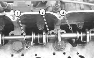
Illustration 4 g00630566
4. Remove bolts (1) and remove fuel injection control linkage (2). Control lever (3) connects the fuel injection control linkage (2) to the governor.
Note: For information on the inspection procedure for control lever (3), refer to Special Instruction, REHS0601, "Inspection and Modification of the 102-7459 Fuel Injection Control Linkage and the 4P-9048 Fuel Injection Control Linkage".
Copyright 1993 - 2019 Caterpillar Inc. All Rights Reserved. Private Network For SIS Licensees.
Sat Oct 19 22:00:32 UTC+0800 2019
Previous Screen
Product: EXCAVATOR
Model: 322 L EXCAVATOR 9RL


Configuration: 322L EXCAVATOR 9RL00001-UP (MACHINE) POWERED BY 3116 ENGINE
Disassembly and Assembly
446 and 446B Backhoe Loaders, Lexion 450 Combine, 3114 and 3116 Engines, IT18F
Integrated Toolcarrier, D6M Track-Type Tractor and 928F, 950F and 950G Wheel Loaders
Media Number -SENR3611-18
Fuel Injection Control Linkage - Install
SMCS - 1298-012
Installation Procedure
Table 1
Tools
Date
(1) This tool is part of the 128-8822 Governor Tool Group.
i01928573
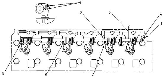
Illustration 1 g00661331
Note: For information on the inspection procedure for control lever (3), refer to Special Instruction, REHS0601, "Inspection and Modification of the 102-7459 Fuel Injection Control Linkage and the 4P -9048 Fuel Injection Control Linkage".
1. Loosen setscrews (4) on each bracket.
2. Install fuel control linkage (2) and install bolts (1). Use the following sequence in order to tighten the bolts.
3. Tighten bracket (A) and (D) to a torque of 12 ± 3 N·m (106 ± 27 lb in).
4. Tighten brackets (B) and (C) to a torque of 12 ± 3 N·m (106 ± 27 lb in).
5. Position brackets (B) and (C) in order to allow free rotation of the fuel control rod.
6. Use a 2.5 mm (0.10 inch) wrench to tighten setscrews (4). Tighten the setscrews to a torque of 3.5 ± 0.2 N·m (31 ± 2 lb in). Do not overtighten the setscrews. Ensure that the control rod rotates freely.
7. The control rod should rotate freely when a force of 4.4 N (1 lb) or less is applied to control lever (3).
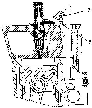
Illustration 2 g00750163
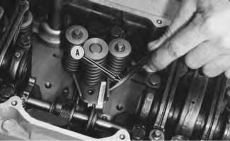
8. Rotate the unit injectors in order to engage the injector rack bar (5) with the fuel injection control linkage (2).
Note: If the unit injectors are not installed, refer to the Disassembly and Assembly, "Unit Injector -
9. Install Tooling (C) on the unit injectors and compress the springs.
Note: For the procedure to install Tooling (C), refer to Tool Operating Manual, NEHS0610, "Using the 128-8822 Tool Group on 3114, 3116, and 3126 Engines with Mechanical Unit Injectors (MUI)".
3
10. Install clevis pin (6) in Tooling (B). Clevis pin (6) attaches the control lever (3) to the governor.
Illustration 4
11. Use Tooling (B) to install clevis pin (6) and the clip.
12. Use Tooling (D) to set the unit injector synchronization.
Note: For the procedure to use Tooling (D), refer to Tool Operating Manual, NEHS0610, "Using the 128-8822 Tool Group on 3114, 3116, and 3126 Engines with Mechanical Unit Injectors (MUI)".
13. Remove Tooling (C) from the unit injectors.
Illustration
g00672755
g00672752
Illustration 5
14. Use Tooling (A) to slide tube assembly (5) into the governor.
Illustration 6
15. Install clip (4).
End By:
a. Install the rocker arm assemblies and the pushrods. Refer to Disassembly and Assembly, "Rocker Shaft and Pushrod - Install".
Copyright 1993 - 2019 Caterpillar Inc. All Rights Reserved. Private Network For SIS Licensees. Sat Oct 19 22:01:28 UTC+0800 2019
g00655975
g00613071
Previous Screen
Product: EXCAVATOR
Model: 322 L EXCAVATOR 9RL
Configuration: 322L EXCAVATOR 9RL00001-UP (MACHINE) POWERED BY 3116 ENGINE
Disassembly and Assembly
446 and 446B Backhoe Loaders, Lexion 450 Combine, 3114 and 3116 Engines, IT18F Integrated Toolcarrier, D6M Track-Type Tractor and 928F, 950F and 950G Wheel Loaders Media Number -SENR3611-18
i05919358
Unit Injector - Remove
SMCS - 1290-011
Removal Procedure
Table 1
Required Tools
Tool Part Number Part Description Qty A 5P-0302 Bar 1
Start By:
A. Remove the rocker shaft and the pushrods. Refer to Disassembly and Assembly, "Rocker Shaft and Pushrod - Remove".
NOTICE
Keep all parts clean from contaminants.
Contaminants may cause rapid wear and shortened component life.
NOTICE
Care must be taken to ensure that fluids are contained during
performance of inspection, maintenance, testing, adjusting, and repair of the product. Be prepared to collect the fluid with suitable containers
before opening any compartment or disassembling any component containing fluids.
Refer to Special Publication, NENG2500, "Dealer Service Tool Catalog" for tools and supplies suitable to collect and contain fluids on Cat products.
Dispose of all fluids according to local regulations and mandates.
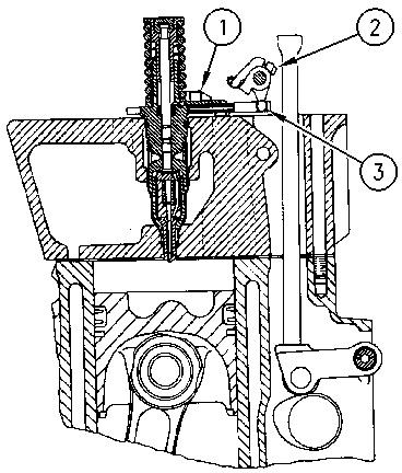
Illustration 1
g00775441
1. Remove fuel injector hold-down bolt (1) .
Note: Do not pry on the injector hold-down bracket. Damage to the unit injector could occur. The unit injector has a notch on the opposite side of the rack. This notch is used for prying the unit injector loose. Some fuel injector racks move freely when the spring is not compressed. Do not move the fuel injector rack without compressing the fuel injector spring slightly. Damage may occur to the unit injector.
2. Use Tooling (A) to loosen the unit injector. Rotate the unit injector in order to disengage injector rack bar (3) from fuel injection control linkage (2) .
3. Remove the unit injector. Ensure that two O-ring seals are on the unit injector.
Illustration 2
g00625237
Previous Screen
Product: EXCAVATOR
Model: 322 L EXCAVATOR 9RL
Configuration: 322L EXCAVATOR 9RL00001-UP (MACHINE) POWERED BY 3116 ENGINE
Disassembly and Assembly
446 and 446B Backhoe Loaders, Lexion 450 Combine, 3114 and 3116 Engines, IT18F Integrated Toolcarrier, D6M Track-Type Tractor and 928F, 950F and 950G Wheel Loaders
-SENR3611-18
Unit Injector - Install
SMCS - 1290-012
Installation Procedure
Table 1
Required Tools
Tool Part Number Part Description
B 4C-5553 Injector Seat Cleaning Brush 1 C 173-1530 Injector Seating Tool 1 D 143-2099 Unit Injector Tool Group (Sleeve Replacement) 1
NOTICE
Keep all parts clean from contaminants.
Contaminants may cause rapid wear and shortened component life.
1. Inspect the unit injector sleeve for pitting and for carbon tracking. Used unit injector sleeves do not need to be reamed unless the seated area is pitted or eroded. If the seated area has excessive carbon deposits, the used unit injector sleeves need to be reamed. Refer to Tool Operating Manual, NEHS0675, "Using the 143-2099 Sleeve Replacement Tool Group on 3114, 3116, and 3126 Engines". Use Tooling (D) to ream injector sleeves.
DOWNLOAD SERVICE REPAIR MANUAL
i05919370
2. Inspect the condition of the O-ring seals on the unit injector. Replace the seals, if necessary.