CONDENSED SERVICE DATA
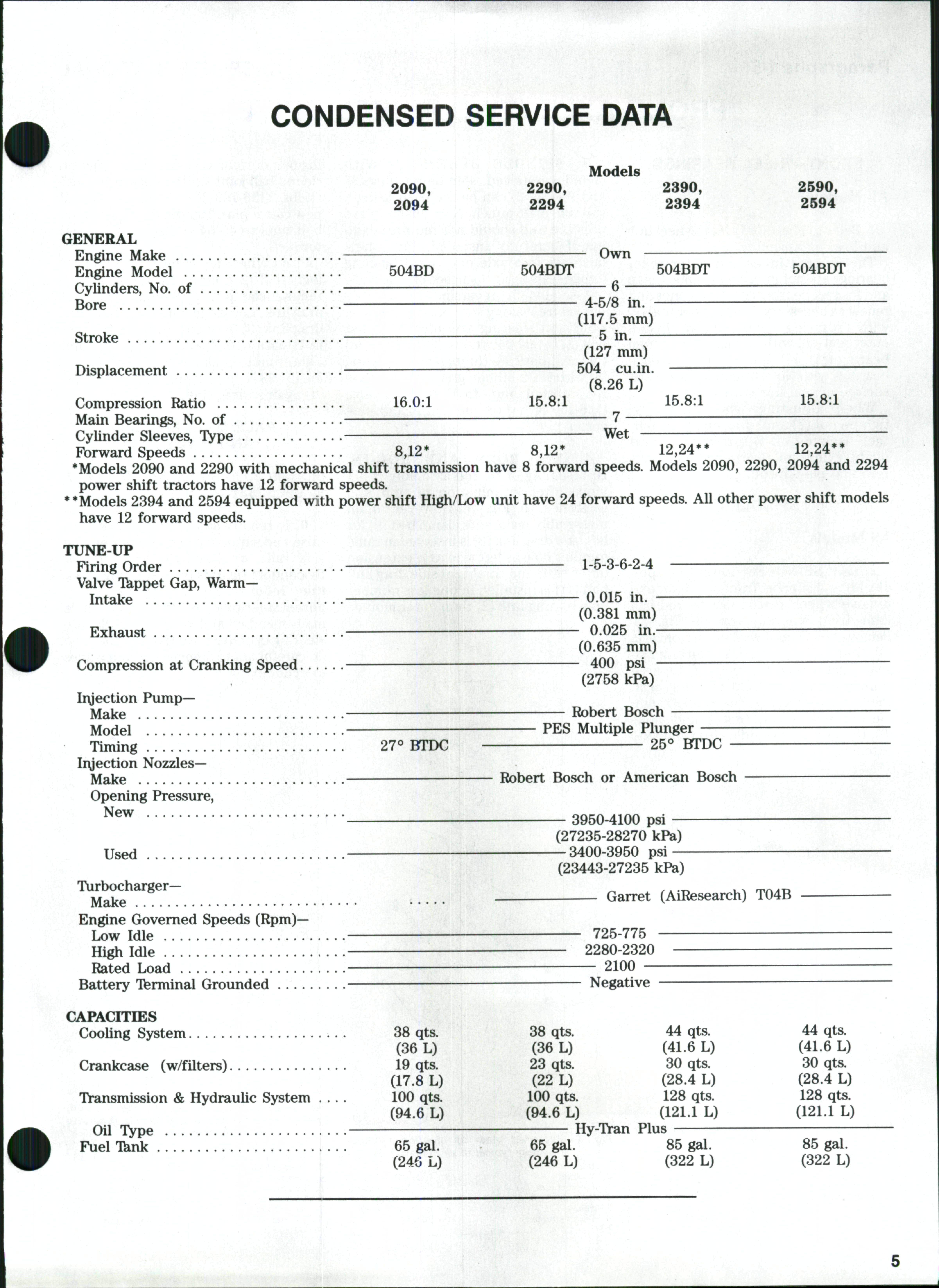
*Models 2090 and 2290 with mechanical shift transmission have 8 forward speeds Models 2090,
power shift tractors have 12 forward speeds.
**Models 2394 and 2594 equipped with power shift High/Low unit have 24 forward speeds. All other power shift models have 12 forward speeds.
Models 2090, 2094 2290, 2294 2390, 2394 2590, 2594 GENERAL Engine Make " Own Engine Model 504BD 504BDT 504BDT 504BDT Cylinders, No of — 6 Bore —•— 4-5/8 in. (117.5 mm) Stroke 5 in — (127 mm) Displacement 504 cu.in — (8.26 L) Compression Ratio 16.0:1 15.8:1 15.8:1 15.8:1 Main Bearings, No of 7 Cylinder Sleeves, TVpe Wet Fbrward Speeds 8,12* 8,12* 12,24** 12,24**
2290, 2094
and 2294
TUNE-UP ' ' ' '' Firing Order 1-5-3-6-2-4 Valve Tkppet Gap, WarmIntake — ^ 0.015 in. (0.381 mm) Exhaust 0.025 in — (0.635 mm) Compression at Cranking Speed — ^ 400 psi (2758 kPa) Iryection PumpMake Robert Bosch Model PES Multiple Plunger Timing 27*» BTDC 25*^ BTDC Iryection NozzlesMake Robert Bosch or American Bosch Opening Pressure, ^®^ • 3950-4100 psi (27235-28270 kPa) Used —3400-3950 psi — (23443-27235 kPa)
(AiResearch) T04B Engine Governed Speeds (Rpm) Low Idle 725-775 High Idle 2280-2320 Rated Load 2100 Battery Tferminal Grounded Negative CAPACITIES Cooling System 38 qts 38 qts 44 qts 44 qts (36 L) (36 L) (41.6 L) (41.6 L) Crankcase (w/filters) 19 qts 23 qts 30 qts 30 qts (17.8 L) (22 L) (28.4 L) (28.4 L) Transmission & Hydraulic System 100 qts. 100 qts. 128 qts. 128 qts. (94.6 L) (94.6 L) (121.1 L) (121.1 L) Oil Type Hy-Tran Plus Fuel Tknk 65 gal. 65 gal. 85 gal. 85 gal. (24G L) (246 L) (322 L) (322 L)
": Garret
Thank you very much for your reading. Please Click Here. Then Get COMPLETE MANUAL.
NOTE:
If there is no response to click on the link above, please download the PDF document first and then clickonit.

NOWAITINGMORE
FRONT AXLE (TWO WHEEL DRIVE)
FRONT WHEEL BEARINGS
All Models '
1.Refer to Fig. 1 for typical wheel hub and bearing assembly
The tapered inner and outer roller bearings are not interchangeable. Clean and inspect bearing cups and cones and renew asnecessary. Install inner seal(9) with lip facing spindle flange Install outer seal(10) with lipfacing away from bearing (11). Fill hub cavity and pack bearings with No 2lithium grease Coat surface of seal lips with grease.
When adjusting wheel bearings, tighten nut (7)until drag on hub is felt, then back nut off Viturn or until next pin hole lines up Bearings should have zero end play. Install cotter pin.
SPINDLES
3. SPINDLE BUSHINGS. With spindles removed, spindle bushings (6 and 9—Fig 2) can be removed using a suitable drift punch New bushings are presized and should not require reaming if carefully installed Press new bushings into axle ends until bushing flange seats against surface of axleends
Assemble by reversing disassembly procedure making sure punch marks on shaft and steering arm align Tighten bolt (1) to 200-250ft.'lbs (271-339 N• m) torque. Lubricate through grease fitting (8)with No 2lithium grease Tighten tie rod slotted nut to 100-125 ft.-lbs. (136-169 N• m) torque and install new cotter pin
ingbolt of right axle extension Tighten tie rod balljoint slotted nuts to 100-125 ft.-lbs (136-169 N-m) torque InstaU new cotter pins.Tighten draglink clamp bolt nuts to 45-54 ft.-lbs (61-73 N• m)
torque
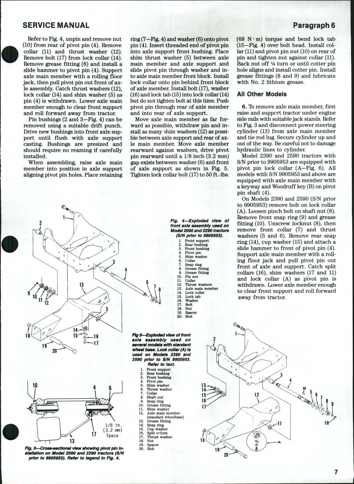
Front wheel toe-in must be 1/8 to 1/2 inch (3.2-12.7 mm) 1b adjust toe-in, remove clamp bolt (9—Fig. 3) on left drag link Loosenjam nut (4), then turn drag link (3)in or out until desired toein is obtained Install clamp bolt and tighten nut on clamp bolt to 45-54 ft.Ibs.(61-73 N • m) torque.Tightenjam nut (4) against drag link
AXLE MAIN MEMBER AND PIVOT PIN
All Models
2 R&R SPINDLES. Ib remove spindle, lift and support front of tractor and remove wheel. Disconnect tie rod ball joint from steering arm (3—Fig 2) Removebolt (1) and washer (2) from arm (3) Note index punch markson arm and shaft indicating location of tapered splines for left or right steering arm, then remove steeringarm Support spindle and remove snap ring (4) and shims (5), then remove spindle (10)from axle extension (7)
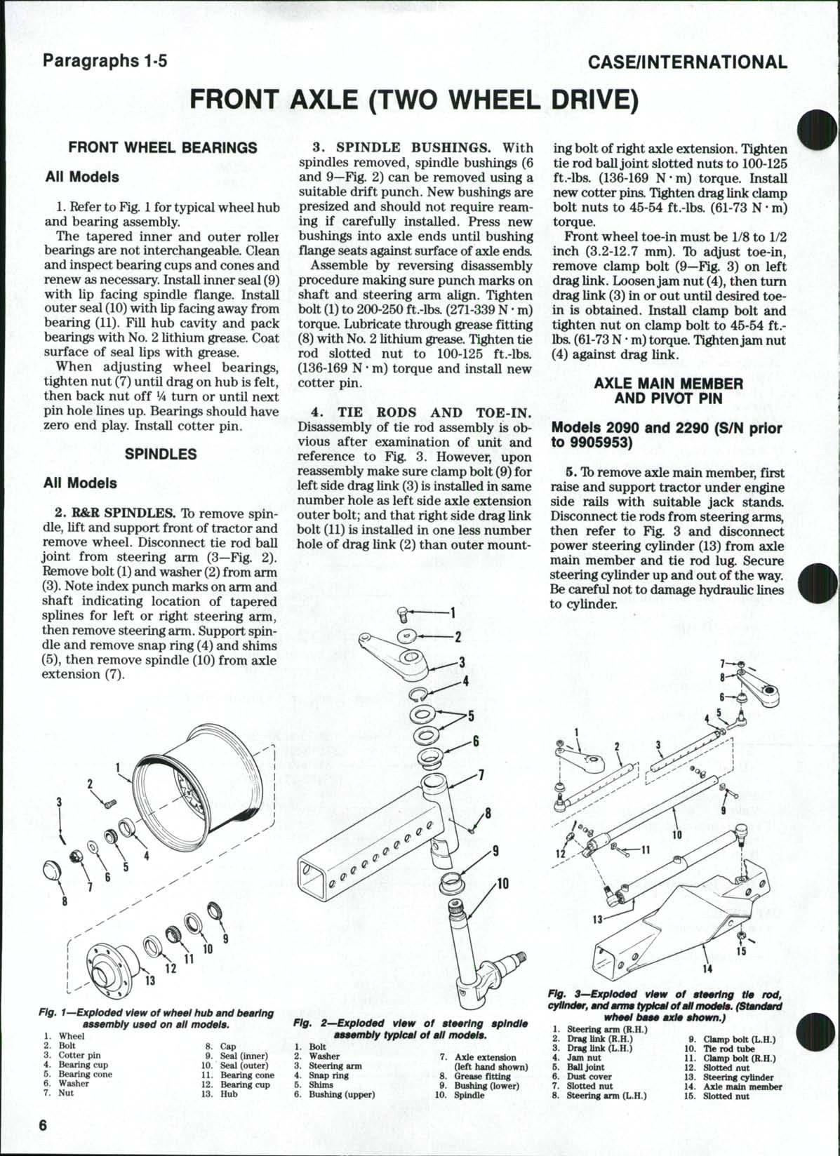
4. TIE RODS AND TOE-IN. Disassembly of tie rod assembly is obvious after examination of unit and reference to Fig 3, However, upon reassembly make sure clampbolt (9) for left side drag link (3)isinstalled in same number hole as left side axle extension outer bolt; and that right side drag link bolt (11)is installed in one less number hole of drag link (2) than outer mount-
Models 2090 and 2290 (S/N prior to 9905953)
5 Tb remove axle main member, first raise and support tractor under engine side rails with suitable jack stands. Disconnect tie rodsfrom steering arms, then refer to Fig. 3 and disconnect power steering cylinder (13) from axle main member and tie rod lug Secure steering cylinder up and out of the way. Becareful not to damage hydraulic lines to cylinder.
1
CASE/INTERNATIONAL
Paragraphs 1-5
1
2 Bolt 8 Cap 3 Cotter pin 9
4 Bearing cup 10 Seal (outer) 5 Bearing cone 11 Bearing cone 6 Washer 12 Bearing cup 7 Nut 13 Hub
1 Bolt 2 Washer 7 Axle extension 3 Steering arm (left hand shown) 4 Snap ring 8 Grease fitting 5 Shims Q. Bushing (lower) 6 Bushing (upper) 10 Spindle
Fig. 1—Exploded view of wheel hub and bearing asaembly used on all model:
Wheel
Seal (inner)
Fig.
2—Exploded view of ateerlng aplndle aaaembly typical of all modela.
12 15 14
Fig. 3^Exploded view of ateertng tie rod, cylinder, and anrrn typical of all modele. (Standard wheel baae axle ahown.}
steering ann (R.H.)
7
nut
2 Drag link
(R.H,)
3 Drag Unk
(L.H.)
4 Jam nut 6 BaUJoint 6 Dust cover
Slotted
8 Steering ami (L.H.)
9. Clmmp bolt (L.H.)
10
Tie rod tube
11 Clamp
bolt (R.H.)
12 Slotted nut 13 Steering cylinder 14 Axle main member 15 Slotted nut
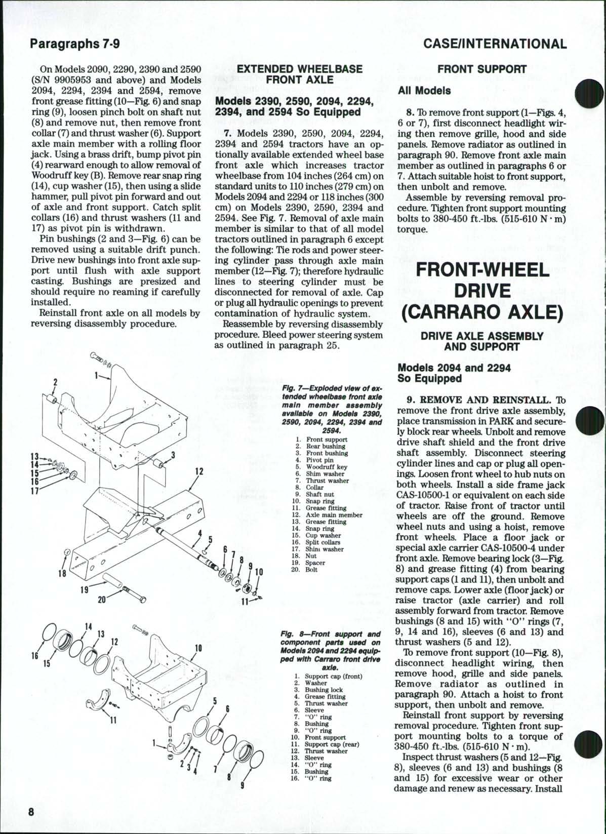
Referto Fig. 4, unpinand remove nut (10) from rear of pivot pin (4). Remove collar (11) and thrust washer (12). Remove bolt (17) from lock collar (14). Remove grease fitting (8) and install a slide hammer to pivot pin (4). Support axle main member with a rolling flo(»r jack, then pullpivot pin out front of axle assembly. Catch thrust washers(12), lock collar (14) and shim washer (5)£is pin (4) is withdrawn. Lower axle main member enough to clear front support and roll forward away from tractor.
Pin bushings (2 and 3—Fig. 4) can be removed using a suitable drift puncli. Drive new bushings into front axlesupport until flush with axle suppoit casting. Bushings are presized and should require no reaming if carefully installed.
When assembling, raise axle main member into position in axle support aligning pivot pin holes. Place retairiing
ring (7—Fig.4) andwasher(6) ontopivot pin(4). Insert threaded end of pivot pin into axle support front bushing. Place shim thrust washer (5) between axle main member and axle support and slide pivot pin through washer and into axle mainmemberfront block. Install lock collar onto pin behind front block of axle member. Install bolt(17), washer (16) andlock tab(15) intolock collar(14) butdonottightenbolt atthistime. Push pivot pin through rear of axle member and into rear of axle support.
Move axle main member as far forward as possible, withdraw pin and install asmany shim washers(12) aspossiblebetween axlesupport andrearofaxle main member. Move axle member rearward against washers, drive pivot pin rearward until a 1/8 inch (3.2 mm) gapexistsbetween washer (6)and front of axle support as shown in Fig. 5. Tightenlock collarbolt(17) to 60 ft.-lba
(68 N-m) torque and bend lock tab (15—Fig. 4) over bolt head. Install collar (11) and pivot pin nut (10) on rearof pin and tighten nut against collar (11). Back nut off V4 turn or until cotter pin hole alignsand install cotter pin. Install grease fittings (8 and 9) and lubricate with No. 2 lithium grease.
All Other Models
6. Tb remove axle main member, first raise and support tractor under engine side railswith suitablejack standa Refer to Fig. 3 and disconnect power steering cylinder (13) from axle main member and tie rod lug. Secure cylinder up and out of the way. Becareful nottodamage hydraulic lines to cylinder.
Model 2390 and 2590 tractors with S/N prior to 9905953 are equipped with pivot pin lock collar (A—Fig. 6). All models with S/N 9905953 andabove are equipped with axle main member with a keyway andWoodruff key(B) onpivot pin shaft (4).
Ftg. 4—Exploded W«iv of front ax/e a999mbfy u—d on Mod0l 2090 and 2290 tncton (S/N prior to 990S9S9h
On Models 2390 and 2590 (S/N prior to 9905953) remove bolt on lock collar (A). Loosen pinch bolt on shaft nut(8). Remove front snap ring (9) and grease fitting (10). Unscrew locknut (8), then remove front collar (7) and thrust washers (5 and 6). Remove rear snap ring (14), cup washer (15) and attach a slide hammer to front of pivot pin (4). Support axle main member with arolling floor jack and pull pivot pin out front of axle and support. Catch split collars (16), shim washers (17 and 11) and lock collar (A) as pivot pin is withdrawn. Loweraxle member enough to clear front support and roU forward away from tractor.
atallaHon on Modal 2090 and 2290 tractora (S/H prior to 990$953}. Rafar to lagand In Fig. 4.
SERVICE MANUAL Paragraph 6
1. Front support 2. Rear bufliUng 3 Front bushing ^ 4 Pivot pin 5. Shim washer '" \ 6. Collar '. 7. Snap ring : 8 Grease fitting 9 Grease fitting 10. Pin nut 11. Collar 12 Thrust washers 13 Axle main member 14 Lock collar 16. Lock tab 16 Washer 17 Bolt 18. Nut 19 Spacer 20 Bolt
20
1 n A. 3 4 5 6 7 8 9. 10 11. 12 13 14. 16. 16 17 18. 19. 20 Rafar to
Front support Front bushing Pivot pin Shim washer Thrust washer Collar Shaft nut Snap dng Grease fitting Shim washer Axle main member (standard wheelbase) Grease fitting Snap ring Cup washer Split collars Thrust washer Nut Spacer Bolt > 13 14 15 16 17 11 r /-, 18'
whaal baaa. Lock collar (A) la uaad on Modala 2390 and 2590 prior to S/N 9905953.
taxt.
Paragraphs 7-9
OnModels2090, 2290, 2390and 2590 (S/N 9905953 and above) and Models 2094, 2294, 2394 and 2594, remove front grease fitting (10—Fig.6)and snap ring (9), loosen pinch bolt on shaft nut (8) and remove nut, then remove front collar (7) and thrust washer (6). Support axle main member with a rolling floor jack. Usingabrass drift, bump pivot pin (4) rearward enough to allow removalof Woodruff key(B) Removerear snap ring (14), cup washer (15), then using aslide hammer, pull pivot pin forward and out of axle and front support Catch split collars (16) and thrust washers (11 and 17) as pivot pinis withdrawn
Pin bushings (2 and 3—Fig 6) can be removed using a suitable drift punch Drive new bushings into front asde support until flush with axle support casting. Bushings are presized and should require noreaming if carefuUy installed
Reinstall front axle on allmodelsby reversing disassembly procedure
EXTENDED WHEELBASE FRONT AXLE
Models 2390, 2590, 2094, 2294, 2394, and 2594 So Equipped
7. Models 2390, 2590, 2094, 2294, 2394 and 2594 tractors have anoptionally available extended wheel base front axle which increases tractor wheelbase from 104 inches (264cm)on standard units to 110 inches (279cm)on Models2094and 2294or 118 inches(300 cm) on Models 2390, 2590, 2394 and 2594. See Fig. 7.Removal of axle main member is similar to that of all model tractors outlined in paragraph 6 except the following: Tie rods and power steering cylinder pass through axle main member (12—Fig.7); therefore hydraulic lines to steering cylinder must be disconnected for removal of axle Cap or plugallhydraulic openingsto prevent contamination of hydraulic system Reassemble by reversing disassembly procedure Bleed power steering system as outlined in paragraph 25
Fig. 7—Exploded view of extended wheeltmae front axle main member assembly available on Models 2390, 2590, 2094, 2294, 2394 and 2S94.
FRONT SUPPORT
All Models
8 Tb remove front support (1—Figs 4, 6 or 7), first disconnect headlight wiring then remove grille, hood and side panels. Remove radiator asoutlined in paragraph 90 Remove front axle main member as outlined inparagraphs 6 or 7.Attach suitable hoist tofront support, then unbolt andremove
Assemble by reversing removal procedure. Tighten front support mounting bolts to 380-450 ft.-lbs (515-610 N • m) torque.
FRONT-WHEEL DRIVE (CARRARO AXLE)
DRIVE AXLE ASSEMBLY AND SUPPORT
Models 2094 and 2294
So Equipped
Fig, 8—Front support and component parts used on Models 2094 and 2294 equipped with Carraro front
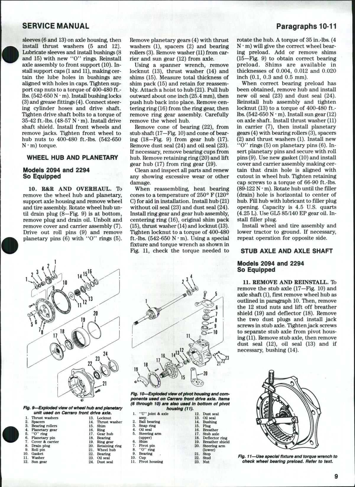
9. REMOVE ANDREINSTALL. Tb remove the front drive axle assembly, place transmission in PARKand securelyblock rear wheels Unbolt and remove drive shaft shield andthe front drive shaft assembly Disconnect steering cylinder lines and cap or plug all openings Loosen front wheel to hub nuts on both wheels. Install a side frame jack CAS-10500-1 or equivalent on each side of tractor. Raise front of tractor until wheels are off the ground Remove wheel nuts andusing a hoist, remove front wheels Place a floor jack or special axle carrier CAS-10500-4 under front axle Removebearing lock(3—Fig 8) and grease fittiiig (4) from bearing support caps(1 and 11),then unbolt and remove caps Lower axle (floorjack) or raise tractor (axle carrier) and roll assembly forward from tractor Remove bushings (8 and 15) with *'O**rings (7, 9, 14and 16), sleeves (6 and 13) and thrust washers (5and 12).
Ib remove front support (10—Fig 8), disconnect headlight wiring, then remove hood, grille and side panels. Remove radiator as outlined in paragraph 90. Attach a hoist to front support, then unbolt andremove Reinstall front support by reversing removal procedure. Tighten front support mounting bolts to a torque of 380-450 ft.-lbs. (515-610 N• m).
Inspect thrust washers(5 and 12—Fig 8), sleeves (6 and 13) andbushings (8 and 15) for excessive wear or other damage and renew asnecessary. Install
CASE/INTERNATIONAL
1 Front support 2 Rear bushing 3 Front bushing 4 Pivotpin 5 Woodruff key 6 Shim washer 7 Thrust washer 8 Collar 0 Shaft nut 10 Snap ring 11 Grease fitting 12 Axle main member 13 Grease fitting 14 Snap ring 16 Cup washer 16 SpUt collars 17 Shint washer 18 Nut 19 Spacer 20 Bolt
axle. 1 Support cap (front) 2 Washer 3 Bushing lock 4 Grease fltting 6 Thrust washer 6 Sleeve 7 "O" ring 8 Bushing 9 "O" ring 10 Front support 11 Support cap (rear) 12 Thrust washer 13 Sleeve 14 "0"ring 16 Bushing 16 "0" ring
drive
sleeves (6and 13) on axle housing, then install thrust washers (5 and 12) Lubricate sleeves and install bushings(8 and 15) with new '*0*' rings Reinstall axle assembly to front support (10). Installsupport caps(1 and 11), maldng certain the lube holes in bushings are aligned with holes in caps. Tighten support cap nuts to a torque of 400-480 ft.lbs.(542-650N• m). Installbushing locks (3) and grease fittings (4) Connect steering cylinder hoses and drive shaft Tighten drive shaft bolts to a torque of 35-42 ft.-lbs (48-57 N • m) InstaUdriv<? shaft shield Install front wheels and remove jacks. Tighten front wheel to hub nuts to 400-480 ft.-lbs (542-650 N• m) torque.
WHEEL HUB AND PLANETARY
Models 2094 and 2294
So Equipped
10. R&R AND OVERHAUL. TD remove the wheel hub and planetarj^, support axle housing and remove wheel and tire assembly Rotate wheel hub until drain plug (8—Fig 9) is at bottom, remove plug and drain oil. Unbolt an<l remove cover and carrier assembly (7) Drive out roll pins (9) and remove planetary pins (6) with *'O'* rings (5)
Remove planetary gears (4)with thrust washers (1), spacers (2) and bearing rollers (3) Removewasher (11) from carrier and sun gear (12) from axle.
Using a spanner wrench, remove locknut (13), thrust washer (14) and shims (15) Measure total thickness of shim pack (15) and retain for reassembly Attach a hoist to hub (21) Pull hub outward about one inch (25.4mm), then push hub back into place. Remove centering ring (16)from the ring gear, then remove ring gear assembly. Carefully remove the wheel hub
Remove cone of bearing (22), from stub shaft (17—Fig. 10) and coneof bearing (18—Fig 9) from gear hub (17) Remove dust seal (24) and oil seal (23) If necessary, remove bearing cups from hub Remove retaining ring (20)and lift gear hub (17) from ring gear (19). Clean and inspect all parts and renew any showing excessive wear or other damage
When reassembling, heat bearing cones to a temperature of 250° F (120*^ C) for aid in installation Install hub(21) without oil seal (23) and dust seal (24) Install ring gear and gear hub assembly, centering ring (16), original shim pack (15),thrust washer (14) and locknut(13). Ti^ten locknut to a torque of 400-480 ft.-lbs (542-650 N • m) Using a special fixture and torque wrench as shown in Fig 11, check the torque needed to
rotate the hub Atorque of 35in.-lba (4 N• m)will give the correct wheel bearing preload Add or remove shims (15—Fig 9) to obtain correct bearing preload. Shims are available in thicknesses of 0.004, 0.012 and 0.020 inch (0.1, 0.3 and 0.5 mm)
When correct bearing preload has been obtained, remove hub and install new oil seal (23) and dust seal (24). Reinstall hub assembly and tighten locknut (13) to a torque of 400-480 ft.lbs. (542-650 N• m).InstaUsun gear (12) on axle shaft Install thrust washer (11) in carrier (7), then install planetary gears(4)with bearing rollers(3), spacers (2) and thrust washers (1) Install new '*0'* rings (5) on planetary pins (6). Insert planetary pins and secure with roll pins (9). Use new gasket (10) and install cover and carrier assembly making certain that drain hole is aligned with cutout in wheel hub. Tighten retaining cap screws to a torque of 66-90 ft.-lbs (89-122N• m) Rotate hub untUthe filler (drain) hole is horizontal to center of hub Finhub with lubricant to filler plug opening. Capacity is 4.5 U.S. quarts (4.25 L) Use GL585/140 EP gear oU InstaU filler plug
Install wheel and tire assembly and lower tractor to ground If necessary, repeat operation for opposite side
STUB AXLE AND AXLE SHAFT
Models 2094 and 2294
So Equipped
11. REMOVE AND REINSTALL. Tb remove the stub axle (17—Fig. 10) and axle shaft (1), first remove wheel hub as outlined in paragraph 10 Then, remove the 12 stud nuts and lift off breather shield (19) and deflector (18) Remove the two dust plugs and install jack screws in stub axle Tightenjack screws to separate stub axle from pivot housing(11).Remove stub axle, then remove dust seal (12), oil seal (13) and if necessary, bushing (14).
SERVICE MANUAL Paragraphs 10-11
1 Thrust washers 13 Locknut 2 Spacers 14 Thrust wa^er 3 Beuing rollers 16 Shim 4 Planetary geu- 16 Ring 5 "O" ring 17 Gear hub 6 Planetary pin 18 Bearing 7 Cover A earner 19 Ring gear 8 Drain plug 20 Retaining ring 9 HoU pin 21 Wheel hub 10 Gasket 22 Bearing 11 Washer 23 OUseal 12 Sun gear 24 Dust seal
Fig. 9—Exploded view of wheel hub and planeiary unit ueed on Cerrmro front drive axle.
1 "U" Joint A axle 12 Dust seal assy 13 Oil seal 2 BaU bearing 14 Bushing 3 Snap ring 15 Plug 4 OUseal 16 Breather 5 Steering arm 17 Stub axle (upper) IB Deflector ring 6 Shim 19 Breather shield 7 Pivot pin 20 Steering arm 8 "O" ring (lower) 9 Bearing 21 Stop 10 Cup 22 Stud 11 Pivot housing 23 Nut
Rg, lO—Exploded view ofpivot houeing end componente ueed on Carrero front drive axle. Iteme ($ through 10) are also used In t>ottom of pivot housing (11).
Fig. 11—Uee special fixture and torque wrench to check wheel bearing preload. Refer to text.
Paragraphs 12-13
Remove upper and lowerhole plugs at outer end of axle housing, then loosen locknuts and remove bearing locating screws. Withdraw axle shaft assembly. Removesnap ring(3) and bearing(2) Oil seal (4) canbe pulled from axle housing, if desired. All parts forthe double '*U'* joint axle shaft are available separately. Procedures for renewing "U" joint crosses and bearings are conventional
When reassembling, install oil seal(4) with lipfacing inward Installbearing(2) and secure with snap ring(3) Lubricate oil seal (4) and carefully install axle shaft (1) Install and tighten upper and lower bearing locatingscrews. TTien, install locknuts and tighten to atorque of 195 ft.lbs (264 N • m)
If removed, install new bushing (14) in stub axle. Install new oilseal (13), but DO NOT bottom in bore Install dust seal (12) until flush with face of bore. Lubricate seals and install stub axle, deflector (18) and breather shield (19) Install stud nuts and tighten to a torque of 203 ft.lbs (275 N• m)
Reinstall wheel hub as outlined in paragraph 10 -
PIVOT HOUSING
Models 2094 and 2294
So Equipped
12. REMOVE AND REINSTALL. Tb remove the pivot housing (11—Fig 10), first remove wheel hub as in paragraph 10 and stub axle and axle shaft asin paragraph 11 Then, disconnect steering cylinder from upper steering arm (5) and tie rod from lowersteeringarm(20)
Unbolt and remove lower steering arm (20) and lower shims (6). Attach a slide hammer to lower pivot pin (7)and remove pivot pin and bearing cone. Unbolt and remove upper steering arm (5) and upper shims (6) Usingaslide hammer, remove upper pivot pin (7) and bearing cone lift offpivot housing(11)
If necessary, use a slide hammer puller to remove bearing cups from axle housing
Clean and inspect all parts and renew asnecessary Heat bearing conesto 250° F (120*=* C)foraid ininstallation Allow to cool and install new '*0'* rings (8). If removed, install bearing cups in axle housing. Pack bearing cones with grease and put grease in cups(10) in axlehousing Install pivot housing and insert pivot pins and bearing cones. Use a plastic hammer and tap pivot pins into position. Install lower steering arm (20) without shims and tighten cap screws to a torque of 30 ft.-lbs (40 N • m) Place all the shims (6)removed from upper and lower pivot pins plus another shim of 0.020 inch (0.5 mm)thickness on the
upper pivot pin Install upper steering arm (5) and tighten cap screws to a torque of 30 ft.-lbs. (40 N• m). Using a feeler gage, measure the distance between upper steering arm and machined surface on pivot housing Remove upper steering arm and all shims. Measure shim pack thickness. Subtract shims equal to the measured distance between steering arm and pivot housing from shim pack Divide remaining shims by two Place each shim pack half plus an additional 0.006-0.008 inch (0.15-0.20 mm) shim under each steering arm to provide 0.012-0.016 inch (0.3-0.4 mm)total bearing preload Tighten upper and lower steering arm cap screws to a torqueof 317 ft.-lbs (430 N • m)
Complete balance of installation by reversing the removal procedure
DIFFERENTIAL AND BEVEL DRIVE GEARS
Models 2094 and 2294
So Equipped
13. R&R AND OVERHAUL. Ib remove thedifferential assembly, first remove front drive axle assembly as outlined inparagraph 9 Then, remove wheel hubs and planetarys as in paragraph 10andstub axles and axle shafts asin paragraph 11 Remove steering cylinders and tie rod. Remove drain plugand drain lubricant from axlehousing.Attach ahoist to differential carrier, then unbolt and remove differential assembly
NOTE: It may be necessary to use |ack screws to force differential carrier from axle housing.
Place assembly on a bench and remove yoke from pinion shaft. Place match marks on carrier (8—Fig 12)and bearing support caps (9). Remove both adjusting ring locks Remove retaining nuts and lift off support bracket (10), bearing support caps (9) and adjusting rings (1 and 17—Fig 13) Remove differential and ringgear assembly and set aside for later disassembly
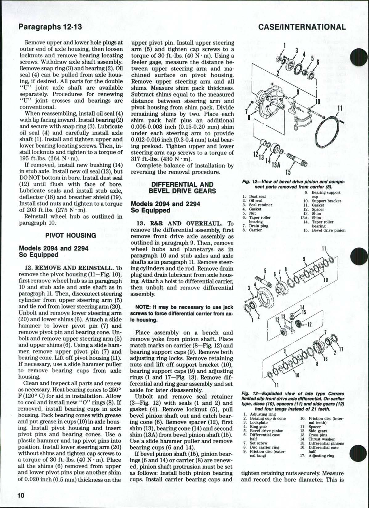
Unbolt and remove seal retainer (3—Fig. 12) with seals (1 and 2) and gasket (4) Remove locknut (5), pull bevel pinion shaft outand catch bearing cone (6). Remove spacer (12), first shim (13), bearing cone (14)and second shim (13A)from bevel pinion shaft (15). Use a slide hammer puller and remove bearing cups (6and 14).
If bevel pinion shaft (15), pinion bearings (6 and 14)or carrier (8)are renewed, pinion shaft protrusion must be set as follows: Install both pinion bearing cups. Install carrier bearing caps and
121314
Fig. 12—View of bevel drive pinion and component parts removed from carrier (8).
9 Bearing support
1 Dust seal cap
2 Oil seal 10 Support bracket
3 Seal retainer U Gasket
4 Gasket 12 Spacer
B Nut 13 Shim
6 Taper roller 13A Shim bearing 14 Taper roller
7 Drain plug bearing
8 Carrier 15 Bevel drive pinion
Fig. 13—Exploded view of late type Carrara limited slip front drive axle differential. On earlier type, discs (10), spacers (11) and side gears (12) had four tangs Instead of 21 teeth.
1 Adjusting ring
2 Bearing cup & cone 10 Friction disc (inter-
3 Lockplate nal teeth)
4 Ring gear 11 Spacer
5 Bevel drive pinion 12 Side gears
6 Differential case 13 Cross pins half 14 Thrust washer
7 Setscrew 15 Differential pinions
8 Disc carrier ring 16 EHfferential case
9 Friction disc (exter- half nal tang) 17 Adjusting ring
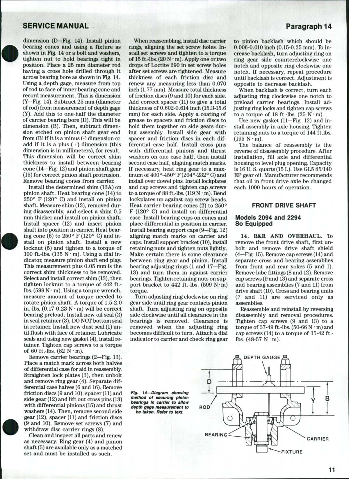
tighten retaining nuts securely Measure and record the bore diameter. This is
CASE/INTERNATIONAL
10
dimension (D—Fig 14) Install pinion bearing cones and using a fixture as shown inFig. 14ora bolt and washers, tighten nut to hold bearings tight in position. Place a 25mm diameter rod having a cross hole drilled through it across bearing bore as shown in Fig 14
Using a depth gage, measure from top of rod to face of inner bearing cone and record measurement This is dimension (Y—Fig 14) Subtract 25 mm (diameter of rod)from measurement of depth gage (Y). Add this to one-half the diameter of carrier bearing bore (D) This will be dimension (B) Then, subtract dimension etched on pinion shaft gear end from fB) ifitisaminus f-ldimensionor add if it is a plus (+) dimension (this dimension is in millimeters), for result This dimension wiU be correct shim thickness to install between bearing cone (14—Fig 12) and pinion shaft gear (15) for correct pinion shaft protrusion. Remove bearing cones from carrier
Install the determined shim (13A) on pinion shaft. Heat bearing cone (14) to 250° F (120*^ C)and install on pinion shaft Measure shim (13), removed during disassembly, andselect a shim 0,5 mm thicker and install on pinion shaft
Install spacer (12) and insert pinion shaft into position in carrier Heat bearing cone (6) to 250° F(120° C) and install on pinion shaft. Install a new locknut (5) andtighten to a torque of 100 ft.-lbs (135 N • m) Using a dialindicator, measure pinion shaft end play This measurement plus 0.05 mm is the correct shim thickness tobe removed. Select and install correct shim (13), then tighten locknut to a torque of 442 ft.lbs. (599N • m). Usingatorque wrench, measure amount of torque needed to rotate pinion shaft. Atorque of 1.5-2.0 in.-lbs (0.17-0.23 N• m) will be correct bearing preload Install new oil seal (2) in seal retainer (3). DO NOTbottom sejil in retainer Install new dust seal (1) until fiush with face of retainer. Lubricate sealsand using new gasket (4), install n;tainer Tighten cap screws to a torque of 60ft.-lbs. (82 N • m).
Remove carrier bearings (2—Fig 13)
Place a match mark across both halveis of differential case for aid in reassembly
Straighten lock plates (3), then unbolt and remove ring gear (4) Separate differential case halves (6and 16) Remove friction discs(9and 10),spacer (11) and side gear (12) and lift out cross pins(13) with differential pinions (15) and thrust washers (14) Then, remove second side gear (12), spacer (11) and friction discs (9 and 10). Remove set screws (7) and withdraw disc carrier rings (8)
Clean and inspect allparts and renew as necessary Ring gear (4) and pinion shaft (5)are available only as a matched set andmust be installed as such.
When reassembling, install disc carrier rings, aligning the set screw holes Install set screws and tighten toa torque of 15 ft.-lbs. (20N • m). Apply one or two drops of Loctite 290 insetscrew holes after set screws are tightened. Measure thickness of each friction disc and renew any measuring less than 0.070 inch (1.77 mm).Measure total thickness of friction discs (9and 10) for each side Add correct spacer (11) to give a total thickness of0.602-0.614 inch (15.3-15.6 mm) for each side Apply a coating of grease to spacers andfriction discs to hold them together onside gearsduring assembly. Install side gear with spacer and friction discs in each differential case half Install cross pins with differential pinions and thrust washers on one case half, then install second case half, aligning match marka If necessary, heat ring gear to a maximum of 400°-450° F(204°-232° C)and install over dowel pins. Install lockplates and cap screws and tighten cap screws toatorque of 88 ft.-lbs (119 N• m) Bend lockplates upagainst cap screw heads. Heat carrier bearing cones (2) to 250° F (120° C) and install on differential case Install bearing cups on cones and place differential in position incarrier InstaU bearing support caps(9—Fig. 12) aligning match marks on carrier and caps. Install support bracket (10), install retaining nuts and tighten nuts lightly Make certain there is some clearance between ring gear and pinion. Install bearing adjusting rings (1 and17—Fig 13) and turn them in against carrier bearings Tighten retaining nuts on support bracket to 442 ft.-lbs (599 Nm) torque.
Turn adjusting ring clockwise on ring gear side until ring gear contacts pinion shaft Turn adjusting ring on opposite side clockwise until all clearance in the bearings is removed Clearance is removed when the acyusting ring becomes difficult to turn. Attach a dial indicator to carrier and check ring gear
to pinion backlash which should be 0.006-0.010 inch (0.15-0.25 mm) Tbincrease backlash, turn ac^usting ring on ring gear side counterclockwise one notch and opposite ring clockwiseone notch. If necessary, repeat procedure until backlash is correct At^justment is opposite to decrease backlash
When backlash is correct, turn each adjusting ring clockwise one notch to preload carrier bearings. Install adjusting ringlocksand tighten cap screws to a torque of 18 ft.-lbs (25 N• m)
Use new gasket (11—Fig 12) and install assembly inaxle housing. Tighten retaining nuts toa torque of 144 ft.lbs (195 N • m)
The balance of reassembly is the reverse ofdisassembly procedure. After installation, fill axle and differential housing to level plug opening. Capacity is 16 U S quarts (15L) Use GL585/140 EP gear oil Manufacturer recommends that oil in front drive axle be changed each 1000 hours of operation
FRONT DRIVE SHAFT
Models 2094 and 2294
So Equipped
14. R&R AND OVERHAUL. TD remove thefront drive shaft, first unbolt and remove drive shaft shield (4—F^ 15) Remove cap screws(14)and separate cross and bearing assemblies from front and rear yokes (5 and1). Remove lube fittings (8and 12) Remove cap screws (9and 13) and separate cross and bearing assemblies (7 and 11) from drive shaft (10) Crossand bearing units (7 and 11) are serviced only as assemblies
Reassemble and reinstall by reversing disassembly and removal procedures. Tighten cap screws (9 and 13) to a torque of 37-49ft.-lbs. (50-66N• m) and cap screws (14)to atorque of35-42ft.lbs (48-57 N • m)
SERVICE MANUAL Paragraph 14
BEARING CARRIER IXTURE 11
Fig. 14—Dlagram showing method of securing pinion bearings In carrier to allow depth gage measurement to be taken. Refer to text. ROD
TRANSFER GEARBOX
Models 2094 and 2294
So Equipped
15. R&R AND OVERHAUL GEARBOX. Tb remove thetransfer gearbox, remove drain plugat bottom of gearbox and drain oil. Unbolt and remove drive shaft shield and front drive shaft
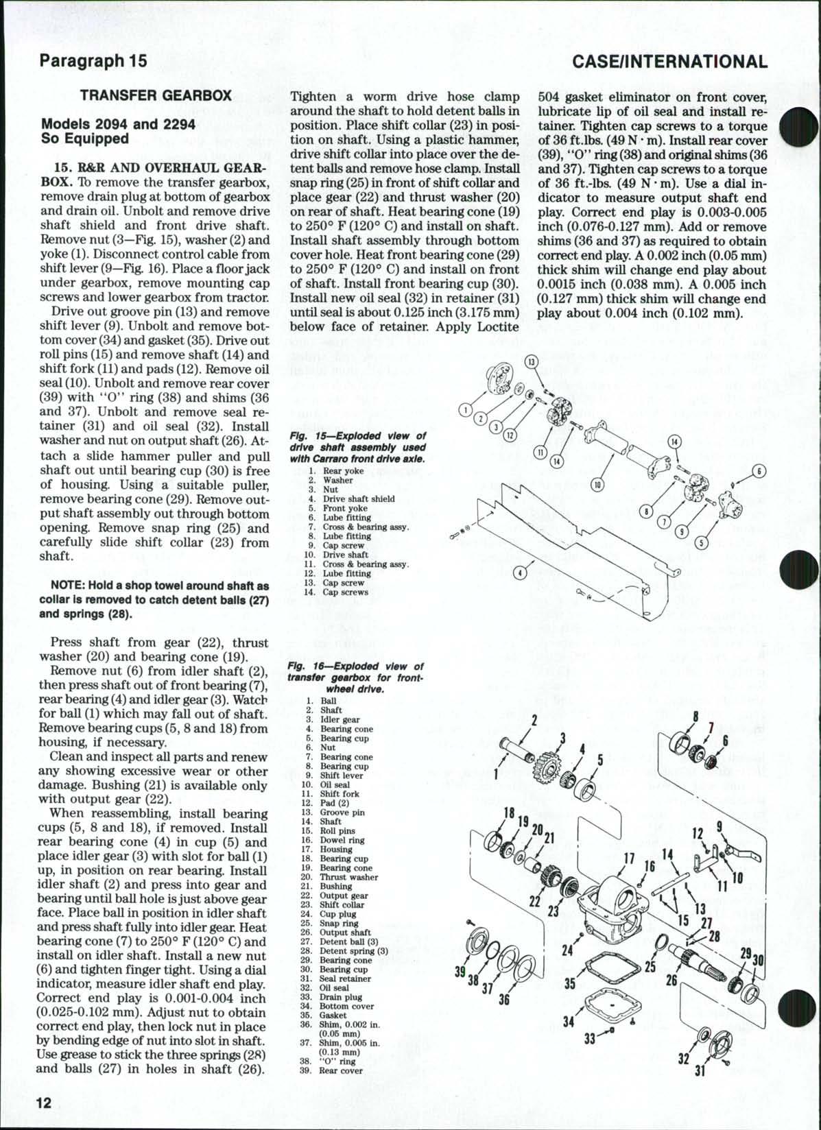
Remove nut (3—Fig 15),washer (2)and yoke (1). Disconnect control cable from shift lever {9—Fig. 16) Place afloor jack under gearbox, remove mounting cap screws and lower gearbox from tractor Drive out groove pin (13)and remove shift lever (9). Unbolt and remove bottom cover(34) and gasket (35) Drive out roll pins (15) and remove shaft (14) and shift fork (11) and pads (12). Remove oil seal (10) Unbolt and remove rear cover (39) with "0"ring (38) andshims(36 and 37) Unbolt and remove seal retainer (31) and oil seal (32) InstaU washer and nut on output shaft (26). Attach a slide hammer puller and pull shaft outuntil bearing cup (30) is free of housing Using a suitable puller, remove bearing cone (29) Remove output shaft assembly out through bottom opening Remove snap ring (25) and carefully slide shift collar (23) from shaft
NOTE: Hold a shop towel around shaft as collar is removed to catch detent balls (27) and springs (28)
Press shaft from gear (22), thrust washer (20) andbearing cone (19).
Remove nut (6)from idler shaft (2), then press shaft out of front bearing (7), rear bearing (4) and idler gear (3) Watch for ball (1) which may fall out of shaft. Removebearing cups (5, 8and 18) from housing, if necessary.
Clean and inspect allparts and renew any showing excessive wear or other damage Bushing (21) is available only with output gear (22),
When reassembling, install bearing cups (5, 8 and 18), if removed. InstaU rear bearing cone (4) in cup (5) and place idler gear (3) with slot for ball(1) up, in position on rear bearing Install idler shaft (2) andpress into gearand bearing until ball hole isjust above gear face Place ball in position in idler shaft and pressshaft fully into idlergear. Heat bearing cone (7)to 250° F (120*=* C) and install on idler shaft. Install a newnut (6)and tighten finger tight Usingadial indicator, measure idler shaft end play. Correct end play is 0.001-0.004 inch (0.025-0.102 mm) Ac^ust nut to obtain correct end play, then lock nut in place bybending edge of nut intoslot in shaft
Usegrease to stick the three springs(28) and balls (27)in holes in shaft (26)
Tighten a worm drive hose clamp around the shaft to hold detent balls in position Place shift collar (23) inposition onshaft. Using a plastic hammer, drive shift collar into place over the detent ballsand remove hoseclamp. Install snap ring (25)in front of shift coUar and place gear (22) andthrust washer (20) on rear ofshaft. Heat bearing cone (19) to 250*^F(120° C)and install on shaft Install shaft assembly through bottom cover hole Heat front bearing cone (29) to 250° F(120° C) and install on front of shaft. Install front bearing cup (30). Install new oil seal (32) inretainer (31) until seal isabout 0.125inch (3.175mm) below face of retainer Apply Loctite
504 gasket eliminator on front cover, lubricate Up of oil seal and instaU retainer. Tighten cap screws to a torque of 36ft.lbs. (49N• m).InstaUrear cover (39), "0" ring(38) and originalshims(36 and 37) Tighten cap screws to a torque of 36 ft.-lbs. (49N• m). Usea dial indicator to measure output shaft end play Correct end play is 0.003-0.005 inch (0.076-0.127 mm) Add or remove shims (36 and 37) as required to obtain correct end play A0.002 inch (0.05mm) thick shim wiU change endplay about 0.0015 inch (0.038 mm) A 0.005 inch (0.127 mm) thick shim wiU change end play about 0.004 inch (0.102 mm)
CASE/INTERNATIONAL
Paragraph 15
1 2 3 4 5 6 7 8 9 10 11 12 13 14 Rear yoke Washer Nut Drive shaft shield Front yoke Lube fitting Cross &bearing assy Lube fitting Cap screw Drive shaft Cross & bearing assy Lube fitting Cap screw Cap screws Ffg.
frontwheel drive. 1. Ball 2 Shaft 3 Idler gear 4 Bearing cone 6. Bearing cup 6 Nut 7 Bearing cone 8 Bearing cup 9 Shift lever 10 OUseal 11 Shift fork 12 Pad (2) 13 Groovepin 14 Shaft 15 Roll pins 16 Dowel ring 17 Housing 18 Bearing cup 19 Bearing cone 20 Thrust washer 21 Bushing 22 Output gear 23 Shift collar 24 Cup plug 26 Snap ring 26 Output shaft 27 Detent ball (3) 28 Detent spring (3) 29 Bearing cone 30 Bearing cup 31 Seal retainer 32 OUseal 33 Drain plug 34 Bottom cover 36 Gasket 36 Shim, 0.002 in (0.06 mm) 37 Shim, 0.005in (0.13 mm) 38 "O" ring 39 Rear cover 12
Fig. 15—Exploded view of drive shaft assembly used with Cairaro front drive axle.
16—Exploded view of transfer gearbox for
SERVICE MANUAL
If necessary to renew cup plug (24), apply a light coat of Permatex No 2 to plug and drive plug inuntil flush with outside of housing. Install anew oilseal (10)with lip to inside Install shift pads (12) in shift fork (11), then install fork assembly and shaft (14) in housing
Secure with roll pins (15) Use new gasket (35) and installbottom cover(34). Tighten cap screws toa torque of 7 ft.lbs (10N • m) Install shift lever (9) and secure with groove pin (13). Apply Loctite 504 gasket eliminator on mounting surface ofgearbox Using: a floorjack, raise gearbox into position Install mounting cap screws and tighter to a torque of 106-127 ft.-lbs (144-172 N• m) Connect control cable to shift lever. Install rear yoke (1—Fig. 15), washer (2) andnut(3) Tighten nut to a torque of 280-340 ft.-lbs. (379-461 N• m) Reinstall drive shaft and tighten cap screws to a torque of 35-42 ft.-lbs (48-57 N • m). Install drive shaft shield. Filltransmission and transfer gearbox to correct level with Hy-Tran Plus fluid
16. R&RAND OVERHAUL INPUT
SHAFT. Tb remove theinput shaft for the transfer gearbox, first split tractoi between the torque tube and transmission case as outlined inparagraph 161 Drive a small chisel under edge of nut (5—Fig 17) to unstake the nut from slots in shaft Remove nut from input shaft Remove the three cap screws (8) and remove input shaft assembly from torque tube
Place housing in a press and press shaft from bearing cone (6) andhousing (9) Remove seal rings (13), then press shaft from bearing cone (12). If necessary, use a suitable puUer to remove bearing cups (7 and 11) from housing.
Clean and inspect all parts and renew any showing excessive wear or other damage.
When reassembling, press bearing cups into housing until bottomed Heat bearing cone (12) to 250° F(120° C) and install oninput shaft. Carefully install seal rings(13) in grooves on shaft, making certain that the hooked ends are engaged Place shaft and bearing in housing Heat bearing cone (6) to 250° F (120° C). Install new nut (5)and tighten nut until it is against bearing cone (6) Use adial indicator and check input shaft endplay. Correct endplay is 0.001-0.004 inch (0.025-0.102 mm) Adjust nut as required to obtain correct end play Then, stake edgeof nut in slots in shaft
Install input shaft assembly in the torque tube andtighten cap screws to a torque of 149-179 ft.-lbs (201-243 N-m). Refer to paragraph 163and reassemble tractor
TIE ROD AND TOE-IN
Models With Carraro
Front Drive Axie
17 Tbe-in should be 0.0-0.060 inch (0.0-1.5 mm) and is ac^usted by lengthening or shortening threaded tie rod ends equally. Tie rod ends are serviced as a complete unit only. 13
Paragraphs 16-18
FRONT-WHEEL DRIVE (ZF AXLE)
DRiVE AXLE ASSEiMBLY AND SUPPORT
iModel 2294 So Equipped
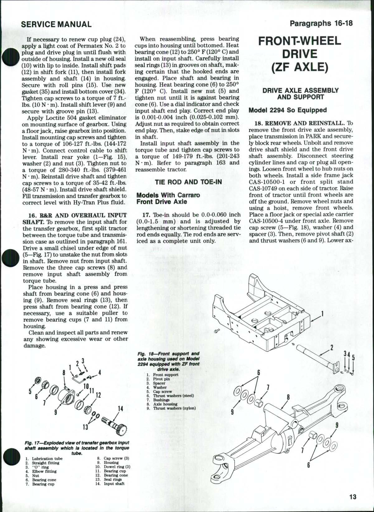
18. REMOVE AND REINSTALL. Tb remove the front drive axle assembly, place transmission in PARKand securelyblock rear wheels. Unbolt and remove drive shaft shield and the front drive shaft assembly Disconnect steering cylinder lines and cap orplug all openings Loosen front wheel to hub nuts on both wheels. Install a side frame jack
CAS-10500-1 or front split stand CAS-10749 on each side of tractor Raise front of tractor until front wheels are off the ground Remove wheel nuts and using a hoist, remove front wheels Place afloorjack or special axle carrier
CAS-10500-4 under front axle Remove cap screw (5—Fig. 18), washer (4) and spacer (3) Then, remove pivot shaft (2) and thrust washers (6and 9) Lower ax-
1 Lubrication tube 8, Cap screw (3) 2 Straight fitting 9 Housing 3 "O" ring 10 Dowel ring (3) 4 Elbow fitting U Bearing cup 5 Nut 12 Bearing cone 6 Bearing cone 13 Seal rings 7 Bearing cup 14 Input shaft
Fig. 17—Exploded view of transfer gearbox Input shaft assmnbly which Is located In the torque tube.
Front support Pivotpin Spacer Washer Cap screw Thrust washers (steel) Bushings Axle housing Thrust washers (nylon) 1 2 4 5 7 8 l^ 13
Flg. 18—Front support and axle housing used on Model 2294 equipped with ZF front drive axle.
Paragraph 19
le (floor jack) orraise tractor (axle carrier) and roll assembly forward from tractor Inspect bushings (7)and renew as necessary. When installing new bushings, apply a coat of Loctite AntiSeize to bore in axle housing. Freeze bushings in dry ice and carefully instaU flush to 1/16inch (1.6 mm) below the face of axle housing.
Tb remove front support (1—Fig 18), disconnect headlight wiring, then remove hood, grille and side panels. Remove radiator as outlined in paragraph 90. Attach a hoist to front support, then unbolt and remove
Reinstall front support by reversing the removal procedure Tighten front support mounting bolts to a torque of 380-450 ft.-lbs (515-610 N• m)
Inspect thrust washers (6and9) for excessive wear and renew as necessary. Reinstall axle assembly to front support Make sure nylon thrust washer (9)isinstalled between steel thrust washers(6), Useas many additional steel washers as possible atrear side ofaxle housing (8) to shim axle housing forward Secure pivot shaft (2) in place with spacer (3), washer (4)and cap screw (5), tightened to 93-112 ft.lbs (126-152 N• m) torque

Connect steering cylinder lines and reinstall drive shaft Tighten drive shaft bolts and nuts to a torque of 45-54 ft.lbs. (61-73 N-m). InstaU drive shaft shield Install front wheels and remove jacks. Tighten front wheel to hub nuts to a torque of 400-480 ft.-lbs (542-650 N-m)
Fig. 20—Exploded view of pivot housing and com~ ponents used on ZF front
WHEEL HUB AND PLANETARY Model 2294 So Equipped
19 R&R AND OVERHAUL Tb remove the wheel huband planetary, support axle housing and remove wheel and tire assembly Rotate wheel hub until drain plug (9—Fig. 19) isat bottom, remove plug and drain oil Removethe
two socket head screws(8), then remove planetary carrier (10) Unbolt and remove lockplate (2) Using a spanner wrench CAS-1762 or equivalent, remove slotted nut (1). Remove ring gear (3), outer bearing cone (5), hub (6) and inner bearing cone (7). If necessary, remove bearing cups (5and7)and oil seal (1- Fig 20) and dust seal (2) from hub. Sun gear (17—Fig. 19) issecured to axle shaft '*U"joint (11-Fig 20) with a snap ring (10). Ifnecessary to remove sun gear, remove pivot housing (5) as outlined in paragraph 20 Ib remove the planetary gears (12-Fig. 19), remove snap rings (14)and slide gear and bearingassemblies from carrier (10).Remove tapered retaining ring (11) and slide bearing (13) from gear (12) Repeat operation forother two gears. Remove thrust washer (15) from center of carrier.
Clean and inspect allparts and renew any showing excessive wear or other damage Remove snap ring (16) and check condition of splined thrust washer (18) and thrust washer (19) Renew as necessary and reassemble on sun gear. Reinstall bearings (13) in planetary gears (12) andinstall retaining ring (11) with wide side of ring towards bearing Install gear assemblies and secure with snap rings (14)
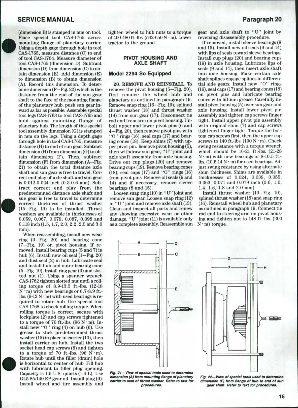
Ib adjust endplay of axle shaft and sun gear, make certain thrust washer (15) is removed from carrier (10). Ib determine dimension (A—Fig 21)which is the distance from thrust washer seat to mounting flange of planetary carrier, install special tool CAS-1764 on thrust washer seat. The length of this tool
CASE/INTERNATIONAL
drive axle. L Oil seal 2 Dust seal 3 Wear ring 4 Pivot pin(lower) 5 Pivot housing 6 Pivot pin(upper) 7 Shim 8 Sleeve bearing 9 OUseal 10 Snap ring 11 "U" joint assy 12 Snap ring 13 Axle shaft 14 Oil seal 15 Sleeve tearing 16 "O" ring 17 Seal cap 18 Bearing cone 19 Bearing cup 20 Cup plug 21 Axle housing 22 Drain plug 23 FiU &level plug
ZF front drive axle. 1 Slotted nut 2. Lockplate 3 Ring gear 4 "O" ring 6 Bearing cup & cone (outer) 6 Hub 7 Bearing cup & cone (inner) 8 Socket head screw 9 Drain plug 10 Planetary carrier 11 Retaining rings 12 Planetary gear 13 RoUer bearing 14 Snap ring 15 Thrust washer 16 Snap ring 17 Sun gear A shaft 18 Splined thrust washer 19 Thrust washer
Fig. 19—Exploded view of wheel hub and planetary unit used on
14
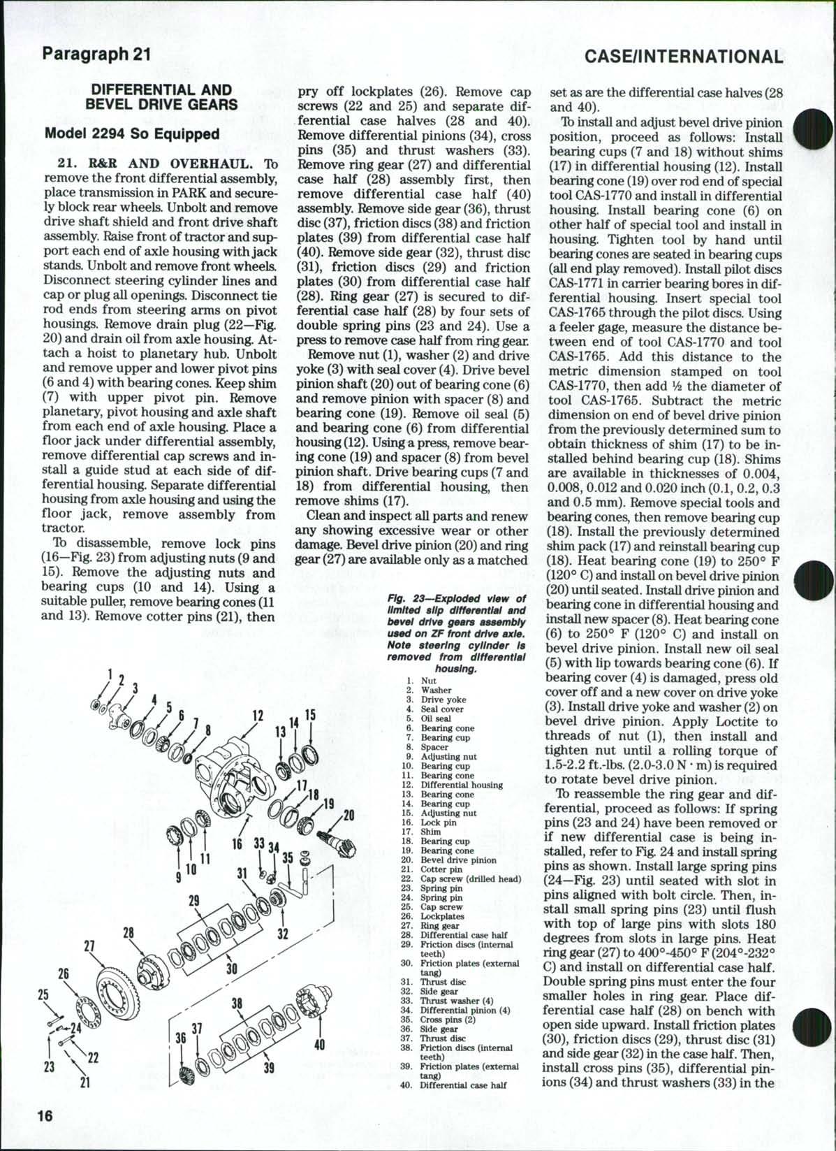
(dimension B) isstamped in mm on tool. Place special tool CAS-1765 across mounting flange of planetary carrier. Usinga depth gage through hole in tool CAS-1765, measure distance (C) to end of tool CAS-1764. Measure diameter of tool CAS-1765 (dimension D) Subtract dimension (D) from dimension (C) toobtain dimension (E). Add dimension (E) to dimension (B) to obtain dimension (A). Record this dimension. Ib determine dimension (F—Fig 22) which is the distance from the end of the sun gear shaft to the face of the mounting flange of the planetary hub, push sun gear inward as far as possible.Assemble special tool legsCAS-1763to tool CAS-1765 and hold against mounting flange of planetary hub.The length of this special tool assembly dimension (G) is stamped in mm on the legs. Using a depth gage through hole in tool CAS-1765, measure distance (H) to end of sun gear Subtract dimension (H) from dimension (G) toobtain dimension (F) Then, subtract dimension (F) from dimension (A—Fig. 21) to obtain the total distance axle shaft and sun gear isfree to travel Correct end play of axle shaft and sun geair is 0.012-0.024 inch (0.3-0.6 mm) Subtract correct end play from the predetermined distance axle shaft and sun gear is free to travel to determine correct thickness of thrust washer (15—Fig 19) to be instaUed Thrust washers are available in thicknesses of 0.059, 0.067, 0.079, 0.087, 0.098 and 0.118inch (1.5, 1.7, 2.0, 2.2, 2.5 and 3.0 mm).
When reassembling, install new wear ring (3—Fig 20) and bearing cone (7—Fig. 19) on pivot housing. If removed, install bearing cups (5 and 7)in hub (6). Install new oil seal (1—Fig. 20) and dust seal (2) in hub Lubricate seal and install hub and outer bearing cone (5—F^g. 19).Install dng gear (3) and slotted nut (1) Using a spanner wrench
CAS-1762tighten slotted nut until arolling torque of 8.9-13.3 ft.-lbs (12-18 N• m) with new bearings or 6.7-8.9 ft.lbs. (9-12N' m)with used bearings is required to rotate hub Use special tool CAS-1768to check rolling torque. When rolling torque is correct, secure with lockplate (2) and cap screws tightened to a torque of 70 ft.-lbs. (96 N• m). Install new *'O*' ring (4) on hub (6) Use grease to stick predetermined thrust washer (15) in place in carrier (10), then install carrier on hub Install the two socket head cap screws (8) and tighten to a torque of 70 ft.-lbs (96 N-m)
Rotate hub until the filler (drain) hole is horizontal to center of hub Fill hub with lubricant to filler plug opening Capacity is 1.5 U.S. quarts (1.4 L). Use GL585/140 EP gear oil InstaU plug(9)
Install wheel and tire assembly and
tighten wheel to hub nuts to a torque of 400-480ft.-lbs (542-650N • m) Lower tractor to the ground
PIVOT HOUSING AND AXLE SHAFT
Model 2294
So Equipped
20. REMOVE AND REINSTALL. Tb remove the pivot housing (5—Fig 20), first remove the wheel hub and planetary as outlined in paragraph 19. Remove snap ring (16—Fig 19), splined thrust washer (18) and thrust washer (19) from sun gear (17) Disconnect tie rod end from arm on pivot housing Unbolt upper and lower pivot pins (6 and 4—Fig 20), then remove pivot pins with *'O'* rings (16), seal caps (17) and bearing cones (18) Keep shims (7) with upper pivot pin Removepivot housing (5), then withdraw sun gear, '^U" joint and axle shaft assembly from axle housing Drive out cup plugs (20) and remove bearing cups (19). Removebearing cones (18), seal caps (17) and **0*' rings (16) from pivot pins. Remove oilseals (9 and 14) and if necessary, remove sleeve bearings (8 and 15)
Loosen snap ring(10) in **U" joint and remove sun gear Loosen snap ring (12) in "U' *joint and remove axle shaft (13) Clean and inspect all parts and renew any showing excessive wear or other damage. **U*' joint (11) isavailable only as a complete assembly Reassemble sun
gear and axle shaft to "U*' joint by reversing disassembly procedure.
If removed, install sleeve bearings (8 and 15) Install new oil seals (9 and 14) with lipsof sealstoward sleeve bearings Install cup plugs (20) and bearing cups (19) in axle housing Lubricate lips of seals (9 and 14), then insert axle shaft into axle housing Make certain axle shaft splines engage splines in differential side gears. Install new "0" rings (16), sealcaps(17) and bearing cones(18) on pivot pins and lubricate bearing cones with lithium grease Carefully install pivot housing (5) over sun gear and axle housing. Install lower pivot pin assembly and tighten cap screws finger tight. Install upper pivot pin assembly with original shim (7) and cap screws tightened finger tight Tbrque the bottom cap screws first, then the upper cap screws to 140ft.-lbs (190 N• m) Check swing resistance with a torque wrench which should be 16-21 ft.-lbs (21-28 N* m) with new bearings or 8-10.5 ft.lbs. (10.5-14N • m)for used bearings.Adjust swing resistance by using alternate shim thickness Shims are available in thicknesses of 0.024, 0.039, 0.055, 0.063, 0.071 and 0.079 inch (0.6, 1.0, 1.4, 1.6, L8 and 2.0 mm).
Install thrust washer (19-Fig 19), splined thrust washer (18) and snap ring (16) Reinstall wheel hub and planetary asoutlined in paragraph 19 Connect tie rod end to steering arm on pivot housing and tighten nut to 148 ft.-lbs (200 N• m) torque.
SERVICE MANUAL Paragraph 20
H
Fig. 21—Vlaw of apaelal toola uaad to datarmlna dimanalon (A} from mounting flanga ofplanatary carriar to aaat of thruat waahar. Rafar to taxt for procaduraa.
15
Fig. 22—Vlaw of apaelal toola uaad to datarmlna dimanalon (F} from flanga of hub to and of aun gaar ahaft. Rafar to taxt for procaduraa.
DIFFERENTIAL AND BEVEL DRIVE GEARS
Model 2294 So Equipped
21. R&R AND OVERHAUL. Ib remove thefront differential assembly, place transmission inPARKandsecurelyblock rear wheels Unbolt and remove drive shaft shield and front drive shaft assembly Raisefront oftractor and support each endof axle housing withjack stands Unbolt andremove front wheels Disconnect steering cylinder lines and cap orplug all openings. Disconnect tie rod ends from steering arms on pivot housings Remove drain plug (22—Fig 20)anddrain oilfrom axle housing.Attach a hoist to planetary hub Unbolt and remove upper andlower pivot pins (6and4)with bearing cones Keep shim (7) with upper pivot pin Remove planetary, pivot housing and axle shaft from each end of axle housing Place a floor jack under differential assembly, remove differential cap screws and instaU a guide stud at each side of differential housing. Separate differential housing from axle housingand usingthe floor jack, remove assembly from tractor Ib disassemble, remove lock pins (16—Fig.23)from adjusting nuts (9 and 15) Remove the adjusting nuts and bearing cups (10 and 14) Using a suitable puller, remove bearingcones (11 and 13) Remove cotter pins (21), then
pry off lockplates (26) Remove cap screws (22 and 25) and separate differential case halves (28 and 40). Remove differential pinions (34), cross pins (35) and thrust washers (33). Remove ring gear (27)and differential case half (28) assembly first, then remove differential case half (40) assembly Remove side gear (36), thrust disc (37), friction discs(38)and friction plates (39) from differential case half (40) Remove side gear (32), thrust disc (31), friction discs (29) and friction plates (30) from differential case half (28). Ring gear (27) is secured to differential case half (28) by four sets of double spring pins (23 and 24) Use a presstoremove case half from ringgear.
Rfemove nut (1), washer (2) and drive yoke (3)with seal cover (4) Drive bevel pinion shaft (20) outofbearing cone(6) and remove pinion with spacer (8)and bearing cone (19) Remove oil seal (5) and bearing cone (6) from differential housing(12) Usingapress, remove bearing cone (19) and spacer (8) from bevel pinion shaft Drive bearing cups (7and 18) from differential housing, then remove shims(17).
Clean andinspect allparts and renew any showing excessive wear or other damage. Bevel drive pinion (20)andring gear (27)are available only asa matched
Fig. 23—Exploded view of limited slip differential and bevel drive gears assembly used on ZF front drive axle. Note steering cylinder Is removed from differential housing.
set as are thedifferential case halves(28 and 40)
Tb install andac^just beveldrive pinion position, proceed as follows: Install bearing cups (7 and 18)without shims (17) in differential housing (12) Install bearingcone (19) overrod endof special tool CAS-1770 andinstall in differential housing Install bearing cone (6) on other half of special tool and install in housing Tighten tool by hand until bearing cones are seated inbearing cups (allendplay removed) Install pilot discs CAS-1771incarrier bearing bores in differential housing. Insert special tool CAS-1765through thepilot discs Using a feeler gage, measure the distancebetween end of tool CAS-1770 and tool CAS-1765 Add this distance to the metric dimension stamped on tool CAS-1770, then add ^A the diameter of tool CAS-1765. Subtract the metric dimension on end of bevel drive pinion from thepreviously determined sum to obtain thickness of shim (17)to be installed behind bearing cup (18) Shims are available in thicknesses of 0.004, 0.008, 0.012 and0.020inch (0.1, 0.2, 0.3 and 0.5 mm) Remove special toolsand bearing cones, then remove bearingcup (18) InstaU the previously determined shim pack (17) and reinstaU bearingcup (18) Heat bearing cone (19) to 250° F (120*^ C) and install onbeveldrive pinion (20) until seated. Installdrive pinionand bearing cone indifferential housing and install new spacer (8) Heat bearing cone (6) to 250'=* F (120^ C) and install on bevel drive pinion Install new oil seal (5)with lip towards bearing cone (6). If bearing cover (4) isdamaged, pressold cover off and a new cover ondrive yoke (3). Install drive yoke andwasher (2) on bevel drive pinion Apply Loctite to threads of nut (1), then install and tighten nut until a rolling torque of 1.5-2.2 ft.-lbs (2.0-3.0 N• m)is required to rotate bevel drive pinion.
drive pinion
Cotter pin
Cap screw (drilled head)
Spring pin
Spring pin
Cap screw
Lockplates
Ring gear
Differential case half
Friction discs (internal teeth)
Friction plates (external tang)
Thrust disc
Side gear
Thrust washer (4)
Differential pinion (4)
Cross pins (2)
Side gear
Thrust disc
Friction discs (internal teeth)
Friction plates (external
Tb reassemble the ring gear and differential, proceed as follows: If spring pins (23 and 24) have been removed or if new differential case is being installed, refer to Fig.24andinstall spring pins as shown Install large spring pins (24—Fig. 23) until seated with slot in pins aligned with bolt circle Then, install small spring pins (23) until flush with top of large pins with slots 180 degrees from slots in large pins Heat ringgear (27)to 400^-450° F (204°-232<=* C) and install on differential case half Double spring pins must enter the four smaller holes in ring gear. Place differential case half (28) on bench with open side upward. Install friction plates (30), friction discs (29), thrust disc (31) and side gear(32) in the case half Then, install cross pins (35), differential pinions (34) andthrust washers (33) inthe
21 CASE/INTERNATIONAL
Paragraph
15
Nut Washer Drive yoke Seal cover OUseal Bearing cone Bearing cup Spacer AcUusting nut Bearing cup Bearing cone Differential housing Bearing cone Bearing cup Adjusting nut Lock pin Shim Bearing cup Bearing cone Bevei
tang) 40 Differential case
1 2 3 4 5 6 7 8 9 10 11 12 13 14 15 16 17 18 19 20 21 22 23 24 25 26 27 28 29 31 32 33 34 35 36 37 38 39
half
16