
Document Title: Function Group: Information Type: Date: Tightening torque, specifications 715 Service Information 2015/7/2 0
Profile:
EXC, EC460C LD [GB]
Go back to Index Page
Tightening torque, specifications
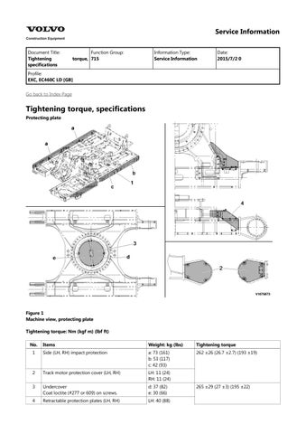
Protecting plate

Figure 1 Machine view, protecting plate Tightening torque: Nm (kgf m) (lbf ft) No. Items
(24) 3 Undercover Coat loctite (#277 or 609) on screws.
Document Title: Function Group: Information Type: Date: Tightening torque, specifications 715 Service Information 2015/7/2 0
Profile:
EXC, EC460C LD [GB]
Go back to Index Page
Tightening torque, specifications
Boom cylinder protecting guard, Demolition standard
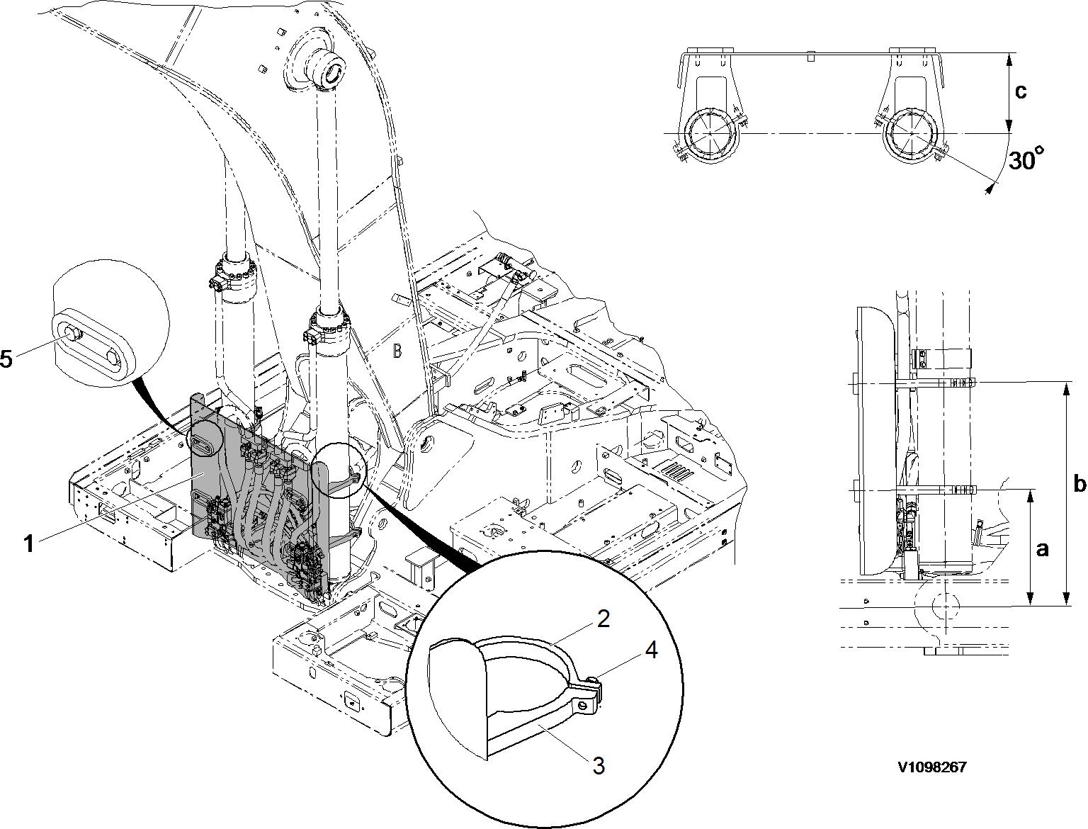
Figure 1 Boom cylinder protecting guard
Tightening torque
Items
b 735 mm (28.94 inch)
c 318 mm (12.52 inch)
NOTE!
Mounting screws. Apply Loctite #277 or equivalent locking fluid.
Document Title: Function Group: Information Type: Date:
Protecting plate, description 715 Service Information 2015/7/2 0
Profile:
EXC, EC460C LD [GB]
Protecting plate, description
Bucket cylinder protecting guard, Demolition
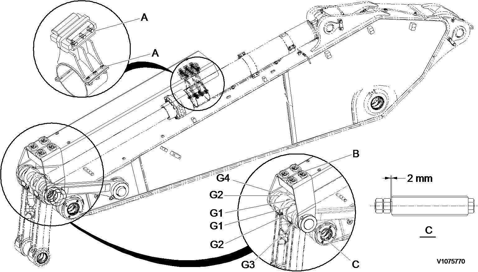
Figure 1
Protecting guard, bucket cylinder (standard)
Gap and shims
NOTE!
The item #4 and #5 before assembly coated grease on the hole inside.

Document Title: Function Group: Information Type:Date: Boom cylinder protecting guard, removal 715 Service Information 2015/7/2 0
Profile:
EXC, EC460C LD [GB]
Go back to Index Page
Boom cylinder protecting guard, removal
Op nbr715-019
1.Park the machine in the service position B, see . 091 Service positions
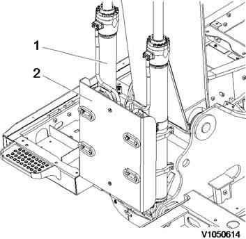
Figure1
Position, boom cylinders
2.Raise boom cylinders (1), to Vertical position and stop engine.
3.Install I-bolt and sling guard (2) securely with a hoist.
NOTE!
Guard weight: 80 kg (176 lbs)
WARNING
The parts are heavy. Take appropriate safety cautions when handling them.
4.Remove screws (3) and guard (2).

Figure2 Remove, guard
5.Remove screws (4) and clamps (5).

Figure3 Remove, clamp
Document Title: Function Group: Information Type:Date: Boom cylinder protecting guard, removal 715 Service Information 2015/7/2 0
Profile:
EXC, EC460C LD [GB]
Go back to Index Page
Boom cylinder protecting guard, removal
Op nbr715-019
1.Park the machine in the service position B, see . 091 Service positions
Figure1
Position, boom cylinders
1. Boom cylinders
2. Sling guard
2.Raise boom cylinders, to Vertical position and stop engine.
3.Install the I-bolt and sling guard securely with a hoist. NOTE!
Guard weight. See . 715 Tightening torque, specifications
WARNING
The parts are heavy. Take appropriate safety cautions when handling them.
4.Remove the screws and guard.
Remove, guard (2) and screws (3)
5.Remove the screws and clamps.
Remove, clamp (5) and screws (4)
Document Title: Function Group: Information Type:Date: Boom cylinder protecting guard, installation 715 Service Information 2015/7/2 0
Profile:
EXC, EC460C LD [GB]
Go back to Index Page
Boom cylinder protecting guard, installation
Op nbr715-020
1.Park the machine in the service position B, see . 091 Service positions
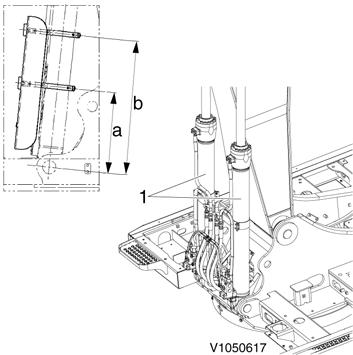
Figure1
Marking, clamp position
a. b. 435 mm (17 inch) 735 mm (29 inch)
2.Raise boom cylinders (1), to Vertical position and stop engine.
3.Mark clamp location on each the boom cylinder (1).
4.Install screws (3) and clamps (2), don't over tighten the clamps (2).
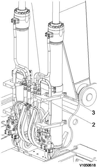
Figure2
Install, clamp
5.Sling guard (4) securely with a hoists and install screws (5).
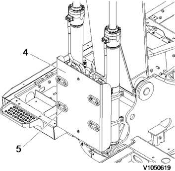
Figure3
Install, guard
NOTE! Apply loctite on screws (5).
NOTE!
Guard weight: 80 kg (176 lbs)
Tightening torque: 262 ±26 Nm (193 ±19 lbf ft)
WARNING
The parts are heavy. Take appropriate safety cautions when handling them.
6.Before installing screws (6) apply loctite.
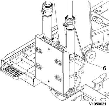
Install, clamp screw NOTE!
Tightening torque: 262 ±26 Nm (193 ±19 lbf ft)
7.Check for interference of guard by operating the boom cylinders.

Document Title: Function Group: Information Type:Date: Boom cylinder protecting guard, installation 715 Service Information 2015/7/2 0
Profile:
EXC, EC460C LD [GB]
Go back to Index Page
Boom cylinder protecting guard, installation
Op nbr715-020
1.Park the machine in the service position B, see . 091 Service positions
Figure1
Marking, clamp position
a. b. XXX mm (XX inch) XXX mm (XX inch)
NOTE!
See . 715 Tightening torque, specifications
2.Raise boom cylinders, to Vertical position and stop engine.
3.Mark clamp location on each the boom cylinder.
4.Install the screws and clamps, don't over tighten the clamps.
Figure2
Install, clamp
2. Clamps
3. Screws
5.Sling guard securely with a hoists and install the screws.
Figure3
Install, guard
4. Sling guard
5. Screws NOTE!
Apply loctite on screws (5).
NOTE!
Guard weight and tightening torque. See . 715 Tightening torque, specifications
WARNING
The parts are heavy. Take appropriate safety cautions when handling them.
6.Before installing screws apply loctite.
Install, clamp screw (6)
NOTE!
Tightening torque. See . 715 Tightening torque, specifications
7.Check for interference of guard by operating the boom cylinders.