
Document Title: Function Group: Information Type:Date:
Foreword additional Service manual Demolition machine 000 Service Information 2015/5/29
Profile: EXC, EC460B LC [GB]
Document Title: Function Group: Information Type:Date:
Foreword additional Service manual Demolition machine 000 Service Information 2015/5/29
Profile: EXC, EC460B LC [GB]
This Service manual for Demolition machine built on base machines EC210B, EC240B, EC290B and EC360B. NOTE!
This is an additional Service manual and should be used together with the Service manual for the base machine.
See Operator’s manual for dimensions and weights for the complete machine. Service work on the machine must not be carried out before the instructions in Section "Safety" in both this Service manual and in the base machine Service manual.
For manual reference numbers, see current publications catalogue and SSI (Service Support Information). The operation numbers refer to "Time Guide". The instructions are based on the use of special tools, E-tools and generally available standard tools.
For supplementary information on special tools, see "Special tools.” Drawings for E-tools can be found in Section 0 (08) General.
Volvo will not accept any responsibility if any lifting devices, tools or work methods other than those described in this publication are used.
The information and data given in this manual are valid at the time of publication. We reserve theright to modify specifications and equipment without prior notification.
Document Title: Function Group: Information Type:Date: Demolition machine, description 000 Service Information 2015/5/29
Profile:
EXC, EC460B LC [GB]
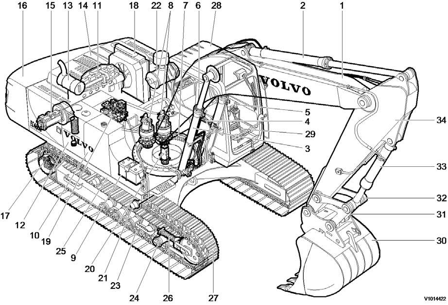
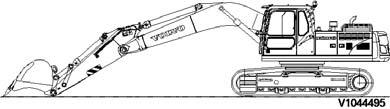
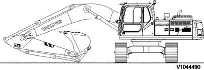
The demolition machine is based on a standard machine.
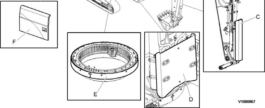
This demolition machine is composed of HD Side door reinforce, Slew ring gear protection cover, Upper frame side protection plate reinforce, Upper under cover reinforce, Boom cylinder protection plate and Bucket cylinder protection plate, Working and maintenance lamps, Top protection round pipe on rear and RH side. See machine view . 000 Machine view, demolition
Document Title: Function Group: Information Type:Date:
Machine view, demolition 000 Service Information 2015/5/29
Profile:
EXC, EC460B LC [GB]
Go back to Index Page
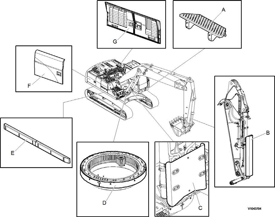
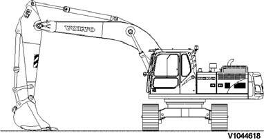
Step, Cabin
Bucket cylinder protecting guard
Boom cylinder protecting guard
Swing ring gear cover
Side impact protection
Auxiliary hood, right side door
Auxiliary hood, left side door
Document Title: Function Group: Information Type:Date:
Machine view, demolition 000 Service Information 2015/5/29
Profile:
EXC, EC460B LC [GB]
Go back to Index Page
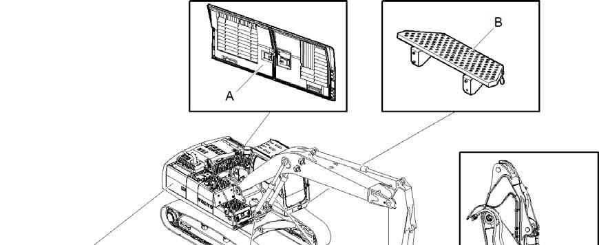
Auxiliary hood, left side door
Step, Cabin
Bucket cylinder protecting guard
Boom cylinder protecting guard
Swing ring gear cover
Auxiliary hood, right side door
Document Title: Function Group: Information Type:Date:
Machine view, waste handler 000 Service Information 2015/5/29
Profile:
EXC, EC460B LC [GB]
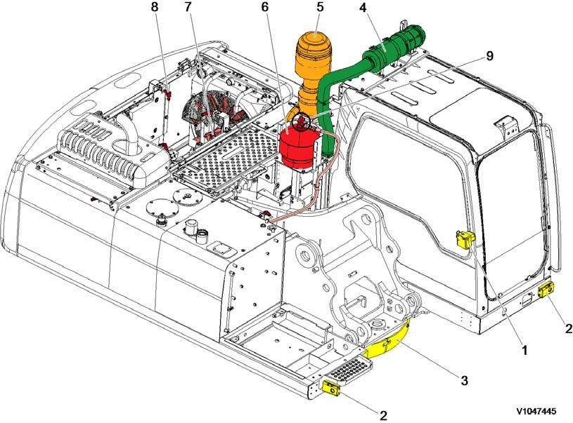
Fire extinguisher fault indicator and battery disconnect switch
Manual actuation switch
Swing ring gear cover
Cab air filtering system
Dual stage pre-cleaner
Fire extinguisher system
Reversible cooling fan system
Nozzle: Engine section (4EA), Hydraulic (2EA)
Agent cylinder
Document Title: Function Group: Information Type:Date: Measurement conversion tables 030 Service Information 2015/5/29
Profile:
EXC, EC460B LC [GB]
Measurement conversion tables
Weight
1 tonne(metric) = 1.1023 ton(US) = 0.9842 ton(UK)
Pressure
Approximate conversions
Torque
(N·m) x 10.2 = kgf·cm x 0.8664 = (lbf·in) newton
(N·m) x 0.74 = lb·ft x 1.36 = N·m newton meter (N·m) x 0.102 = kgf·m x 7.22 = (lbf·ft)
Pressure (Pa = N/m2 )
kilopascal (kPa) x 4.0 = in. H2O x 0.249 = kPa
kilopascal (kPa) x 0.30 = in. Hg x 3.38 = kPa
kilopascal (kPa) x 0.145 = psi x 6.89 = kPa (bar) x 14.5 = psi x 0.069 = (bar)
(kgf/cm2) x 14.22 = psi x 0.070 = (kgf/cm2 ) (newton/mm2 ) x 145.04 = psi x 0.069 = (bar)
megapascal (MPa) x 145 = psi x 0.00689 = MPa
Power (W = J/s)
kilowatt (kW) x 1.36 = PS (cv) x 0.736 = kW kilowatt (kW) x 1.34 = HP x 0.746 = kW
kilowatt (kW) x 0.948 = Btu/s x 1.055 = kW watt (W) x 0.74 = ft·lb/s x 1.36 = W
Energy (J = N·m)
kilojoule (kJ) x 0.948 = Btu x 1.055 = kJ joule (J) x 0.239 = calorie x 4.19 = J
Velocity and Acceleration
meter per sec2 (m/s2 ) x 3.28 = ft/s2 x 0.305 = m/s2 meter per sec (m/s) x 3.28 = ft/s x 0.305 = m/s kilometer per hour (km/h) x 0.62 = mph x 1.61 = km/h
Horse power/torque
BHP x 5252 rpm = TQ (lb·ft)
Temperature
°C = (°F -32) /1.8 °F = (°C x 1.8) + 32
Flow Rate
TQ x rpm 5252 = B.H.P.
liter/min (dm3/min) x 0.264 = US gal/min x 3.785 = liter/min
Note: ( ) non-si unit
Document Title: Function Group: Information Type:Date: Removable counterweight cylinder, specifications 030 Service Information 2015/5/29
Profile:
EXC, EC460B LC [GB]
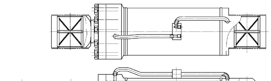
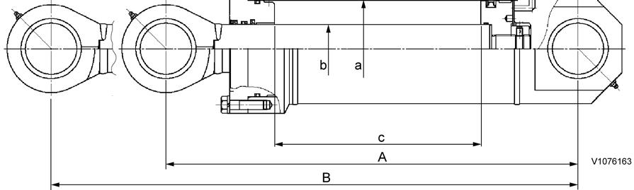
Figure1
Removal counterweight cylinder
Item
Removal cylinder
Center to center distance of pins
Quantity EA 1
Bore (a) × rod (b) × stroke (c) φ160 × φ80 × 3421.5 (φ6.30 × φ3.15 × 134.7) mm (inch)
Full retracted (A)
Full extended (B)
6832 (269)
1025 (40.4)
Cushion EA –
Operating pressure
31.4 MPa (320 kgf cm2) (4552 psi) (313.8 bar)
Weight 170 kg (374.8 lbs)
Document Title: Function Group: Information Type:Date: Standard tightening torques 030 Service Information 2015/5/29
Profile:
EXC, EC460B LC [GB]
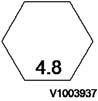
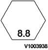
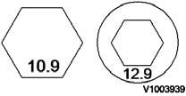
The following charts give the standard tightening torques of screws and nuts. Exceptions are given in each sections of “disassembly and assembly”.
Tightening torque (meter)
Classification
Screw
Tightening torque (inch)
NOTE!
This torque table does not apply to screws with nylon packings or where nonferrous metal washers are to be used, or which require tightening to a different specified torque, or tightening procedure.
NOTE!
N m (Newton meter):1 N m ≅ 0.1 kgf m
Tightening torque of split flange screws
Use these torques for split flange screws.
Tightening torque (split flange screws)
Tightening torque for hydraulic plugs with O-ring
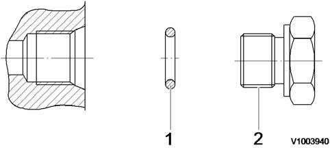
Hydraulic plugs with O-ring
Pf thread
Tightening torque (hydraulic plugs)
Plug
Tightening torque for swivel nut fitting with O-ring
Tightening torque for swivel nut fitting
Document Title:
Document Title: Function Group: Information Type:Date:
NET 8940-00020 Replace tool for the radiator assembly 080 Service Information 2015/5/29
Profile: EXC, EC460B LC [GB]
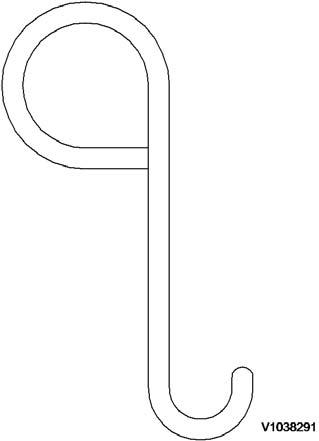
Figure1 Replace tool for the radiator assembly
Document Title: Function Group: Information Type:Date:
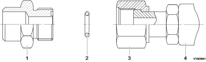
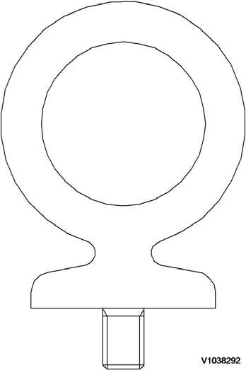
NET 8940-00200 Replace tool for the remote control valve joint 080 Service Information 2015/5/29
Profile:
EXC, EC460B LC [GB]
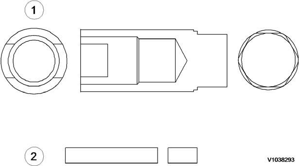
Figure1 Replace tool for the remote control valve joint
1
Document Title: Function Group: Information Type:Date:
NET 8940-00240 Replace tool for the hydraulic tee fitting 080 Service Information 2015/5/29
Profile: EXC, EC460B LC [GB]
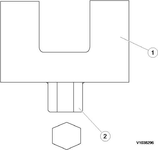
Figure1
Replace tool for the hydraulic tee fitting
Document Title: Function Group:
Type:Date: NET 8940-00210 Inspection tool for the engine speed control switch 080
Profile: EXC, EC460B LC [GB]
Figure1
Document Title: Function Group: Information Type:Date:
NET 8940-00290 Track motor guide pin 080 Service Information 2015/5/29
Profile:
EXC, EC460B LC [GB] NET 8940-00290
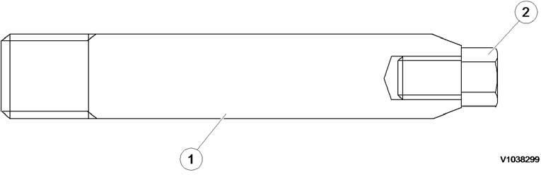
Figure1 Track motor guide pin
Item Quantity Name
Remark
1 2 Guide bar SAE 4130 (25 ~ 35 HRC)
2 2 Screw M8 × 16
Document Title: Function Group:
Type:Date: NET 8940-00220 Inspection tool for the power shift valve 080
Profile: EXC, EC460B LC [GB]
Figure1
Document Title: Function Group: Information Type:Date:
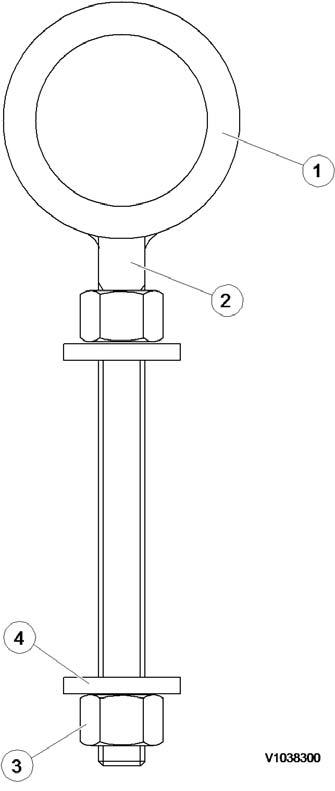
E-tools, NET 8940-00330
Swing motor guide pin 080 Service Information 2015/5/29
Profile:
EXC, EC460B LC [GB]
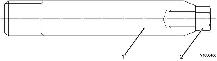
Figure1
Swing motor guide pin
Document Title: Function Group: Information Type:Date:
NET 8940-00250 Replace tool for the hydraulic tee fitting 080 Service Information 2015/5/29
Profile: EXC, EC460B LC [GB]
Document Title: Function Group: Information Type:Date:
NET 8940-00260 Replace tool for the center passage 080 Service Information 2015/5/29
Profile:
EXC, EC460B LC [GB]
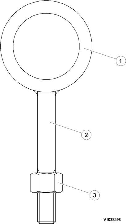
Figure1 Replace tool for the center passage Item
Document Title: Function Group: Information Type:Date: E-tools, NET 8940-00340
Replace tool for the swing ring gear 080 Service Information 2015/5/29
Profile:
EXC, EC460B LC [GB]
Document Title: Function Group: Information Type:Date:
NET E 1678 Center support tool for the air conditioning compressor 080 Service Information 2015/5/29
Profile: EXC, EC460B LC [GB]
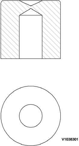
Figure1
Replace tool for the air conditioning compressor
Drawings of E-tools that can be manufactured in the workshop. All dimensions on the drawings are given in mm unless otherwise indicated (1 mm = 0.03937 in).
Document Title: Function Group: Information Type:Date:
Service positions 091 Service Information 2015/5/29
Profile: EXC, EC460B LC [GB]
Park the machine on a horizontal and firm surface.
The suitable position is indicated in the description for the various service jobs.
Service position A
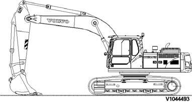
Figure2
Service position B
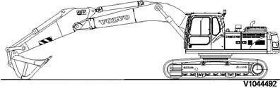
Figure3
Service position C
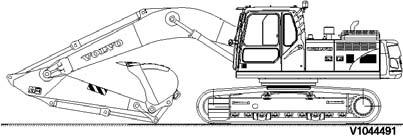
Figure4
Service position D
Service position E
Service position F
Document Title: Function Group: Information Type:Date:
General precautions 191 Service Information 2015/5/29
Profile:
EXC, EC460B LC [GB]
For safety, observe the following rules.
Safety precautions
Figure1
Keep the safety rules
Do not operate the machine if you are under the influence of alcohol, medicine or other drugs. When carrying out any operation or maintenance, have trained and experienced personnel carry out the work. When carrying out any operation or maintenance, carefully read the Operator’s manual. Read all the precautions given on the decals which are fixed to the machine.
Safety device
Make sure that all guards and covers are mounted in their proper position. Repair or replace if damaged. Pay attention to the method of using any safety locking device or safety belt. Fasten the safety belt for all operations.
Safety clothes and hard hat
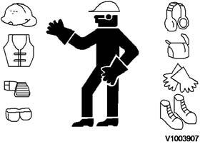
Figure2
Wear clothes suitable for welding work
Wear the specified work clothes in the correct manner.
Use the specified protective gear (hard hat, safety glasses, safety shoes, mask, gloves).
Guard against injury from flying pieces of metal or debris, wear goggles, gloves and helmet.
Always have a trained and experienced welder carry out any welding work.
When carrying out welding work, always wear welding gloves, apron, glasses, cap and other clothes suitable for welding work.
Prepare for emergencies
Figure3
Prepare for emergencies
Know where fire extinguishers are located and how to use them.
Keep a first aid kit and an eye wash kit near the work area.
Keep emergency numbers for doctors, ambulance service, hospital, and fire department near your telephone.
Handle fluids safely-avoid fires
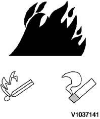
Figure4
Avoid fires
Handle fuel with care. It is highly flammable.
Do not refuel the machine while smoking or when near open flame or sparks.
Always stop the engine before refuelling machine.
Fill the fuel tank outdoors.
Store flammable fluids away from fire hazards.
Do not incinerate or puncture pressurized containers.
Dispose of fluids properly
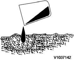
Do not pour oil into the ground
Improperly disposing of fluids can harm the environment and ecology. Before draining any fluids, find out the proper way to dispose of waste from your local environmental agency.
Catch draining fuel, oil, or other fluids in suitable containers.
Do not use food or beverage containers that may mislead someone into drinking from them. Wipe up spills at once.
Do not pour oil into the ground, down a drain, or into a stream, pond, or lake.
Observe relevant environmental protection regulations when disposing of oil, fuel, coolant, filters, batteries, and other harmful waste.
Working in contaminated environment
Avoid breathing dust
Used cab and engine air filters from machines which operate in environments containing asbestos or other dangerous dust must be placed in the tight-fitting bag, before they are deposited in a designated place.
The machine must be equipped for work within an environment which is contaminated or constitutes a health hazard before the work is initiated. Besides, special local regulations apply for such operations and for servicing a machine which has been used in such environment.
Because crystalline silica is a basis component of sand and granite, many activities at construction sites produce dust containing crystalline silica. Trenching, sawing and boring of material containing crystalline silica can produce dust containing crystalline silica.
If dust which contains crystalline silica is present there are guidelines which should be followed.
Be aware of the health effects of crystalline silica and that smoking adds to the damage.
Be aware of and follows OSHA (or other) guidelines for exposure to airborne crystalline silica.
Know the work operations where exposure to crystalline silica may occur.
Participate in air monitoring or training programs offered by the employer.
Be aware of and use optional equipment controls such as water sprays, local exhaust ventilation, and enclosed cabs with positive pressure air conditioning.
Where respirators are required, wear a respirator approved for protection against crystalline silica -containing dust.
Do not alter the respirator in any way. Workers who use tight-fitting respirators cannot have beards/mustaches which interfere with the respirator seal to the face.
If possible, change into disposable or washable work clothes at the work site ; shower and change into clean clothing before leaving the work site.
Do not eat, drink use tobacco products, or apply cosmetics in areas where there is dust containing crystalline silica.
Store food, drink and personal belongings away from the work area.
Wash hands and face before eating, drinking, smoking, or applying cosmetics after leaving the exposure area.
Document Title: Function Group: Information Type:Date:
Cautions during operation 191 Service Information 2015/5/29
Profile:
EXC, EC460B LC [GB]
Service cooling system safely
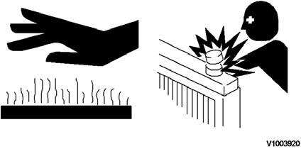
Figure1
Hot coolant can burn you
At operating temperature, the engine coolant is hot and under pressure. The radiator and all lines to the heaters and engine contain hot coolant. Any contact can cause severe burns.
Hot coolant can cause personal injury.
Check the coolant level only after the engine has been stopped and the radiator pressure cap is cool enough to remove with your bare hand.
Remove the radiator pressure cap slowly to release pressure.
Cooling system additive contains alkali that can cause personal injury. Avoid contact with the skin, eyes and mouth. Allow cooling system components to cool before draining.
Avoid high-pressure fluids
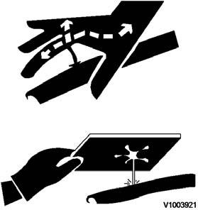
Figure2
Avoid high pressure fluids
Escaping fluid under pressure can penetrate the skin causing serious injury.
Avoid the hazard by releasing pressure before disconnecting hydraulic or other lines.
Tighten all connections before applying pressure.
Fluid leaks under pressure may not be visible. Use a piece of cardboard or wood to find leaks but do not use your bare hand.
Protect hands and body from high pressure fluids.
Be careful not to break, twist or damage the high pressure pipes.
A jet spray of high pressure oil can cause electrical fires.
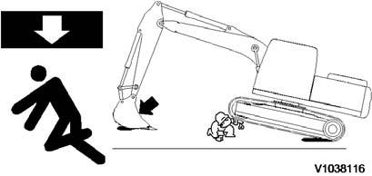
Figure3
Support the equipment safety
When raising heavy components, use a hoist or crane.
Ensure that wire ropes, chains and hooks are free from damage. Always use lifting equipment which has ample capacity.
Install the lifting equipment at the correct places.
Use a hoist or crane and operate slowly to prevent the component hitting any other part.
When disassembling or assembling, support the machine with blocks, jacks or stands before starting work.
Never use concrete blocks for supports. They can collapse under even light loads.
Before starting work, lower the blade, ripper, bucket or any other work equipment to the ground. Do not work under the equipment when the equipment is not sufficiently supported.
Electrical system
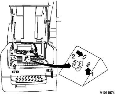
Figure4
ALWAYS turn the master switch OFF when welding on the machine.
When working on the electrical system, ALWAYS turn the master switch OFF or remove the lead from the battery negative (–) terminal.
The battery master switch is installed inside the tool box located on the right side of machine.
When removing components, be careful not to break or damage the wiring.
Damaged wiring can cause electrical fires.
ON position (1)
Turn the key clockwise to supply power to the electrical system. OFF position (2)
Turn the key counter-clockwise to cut off electric power to the machine.
Electric welding
Before electric welding is carried out on the machine or any attachment installed to the machine, the current must be turned OFF at the battery master switch.
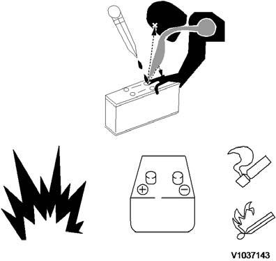
Figure5
When working on the battery, pay attention
Before carrying out any electric welding on the machine, the battery cables should be disconnected and the connectors pulled out of the electronic control units.
When disconnecting and reconnecting, the leads should be without current (the battery master switchturned off).
Connect the earth (ground) lead of the welding equipment as close to the welding point as possible.
Before welding, remove all paint from an area of at least 10 cm (4 inch) around the point of welding. Paint which is heated gives off unhealthy gases.
All paint decomposes when heated and forms a great number of compounds, which may cause irritation and be dangerous to ones health after repeated or prolonged exposure.
In addition to the health hazard, the weld will be of inferior quality and strength, which, in the future, may cause the weld to break. Therefore, never weld directly on a painted surface.
When working on the battery, wear goggles or safety glasses.
Sulfuric acid in battery electrolyte is poisonous.
It is strong enough to burn skin and eat holes in clothing and cause blindness if splashed into theeyes.
If you spill acid on your clothes or skin, immediately flush with large quantities of clean water, then get medical attention.
If splashed into the eyes, flush with water and get medical attention immediately.
Keep sparks, lighted matches, and open flame away from the top of battery. Battery (hydrogen) gas can explode.
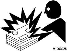
Battery posts and cables can burn you
Battery posts and cables touched by metal objects can short circuit and burn you.
Keep tools away from posts, wires and terminals.
Tighten the battery terminals to ensure good contact.
When disassembling and assembling the battery, make sure that the battery terminals are correctly connected.
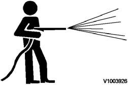
Figure7
Do not use water or steam in the cab
If water gets to the electrical system, abnormal operation or failure can result.
Do not use water or steam on sensors, connectors and instruments in the cab.
Cautions during operation
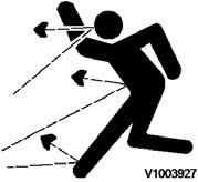
Figure8
Be careful when opening the grease valve
When removing covers which are under internal pressure or under pressure from a spring, always leave two screws in position on opposite sides.
Slowly release the pressure, then slowly loosen the screws.
High pressure grease in the spring package of the undercarriage can explode and injure you.
Be careful when opening the grease valve.
Do not loosen the grease valve more than 1 turn until the pressure is released.
When assembling or installing parts, always use the specified tightening torque.
When installing protective parts such as guards, or parts which rotate at high speed, be particularly careful to check if they are installed correctly.
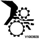
Figure9
Do not contact rotating parts
Be sure that your clothes or hair do not contact any rotating components.
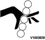
Figure10
Be careful of your finger (1)
When aligning two holes, never insert your fingers or hand.
Be careful not to get your fingers pinched in a hole, or between parts or tools.

Figure11
Be careful of your finger (2)
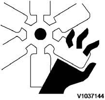
Figure12
Never touch rotating parts
Never touch rotating parts such as the fan blades or fan belt.
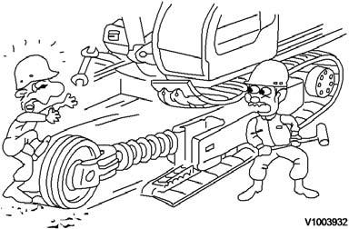
Figure13
Pay attention when removing or installing the tracks
Pay attention when removing or installing the tracks of track type machines. When removing the track pin, the track separates suddenly, so never let anyone stand at either end of the track. Always block both ends of the track to prevent any sudden uncontrolled movement.
Document Title: Function Group: Information Type:Date: Preparations for work 191 Service Information 2015/5/29
Profile:
EXC, EC460B LC [GB]
Warn others of service work
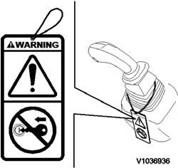
Figure1
Attach a warning tag
Unexpected machine movement can cause serious injury. Before performing any work on the machine, attach a warning tag on the remote control lever. When carrying out any operation with two or more workers, always agree on the operating procedure before starting.
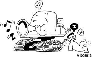
Figure2
Sound the travel alarm
Turn on the travel alarm off switch when you start to move the machine.. Sound the horn and let other workers and bystanders know you are starting the machine.
ignite spilled fuel or oil
Illuminate your work area adequately but safely. Use a portable safety light for working inside or under the machine. Make sure the bulb is enclosedby a wire cage. The hot filament of an accidentally broken bulb can ignite spilled fuel or oil.

Download the full PDF manual instantly.