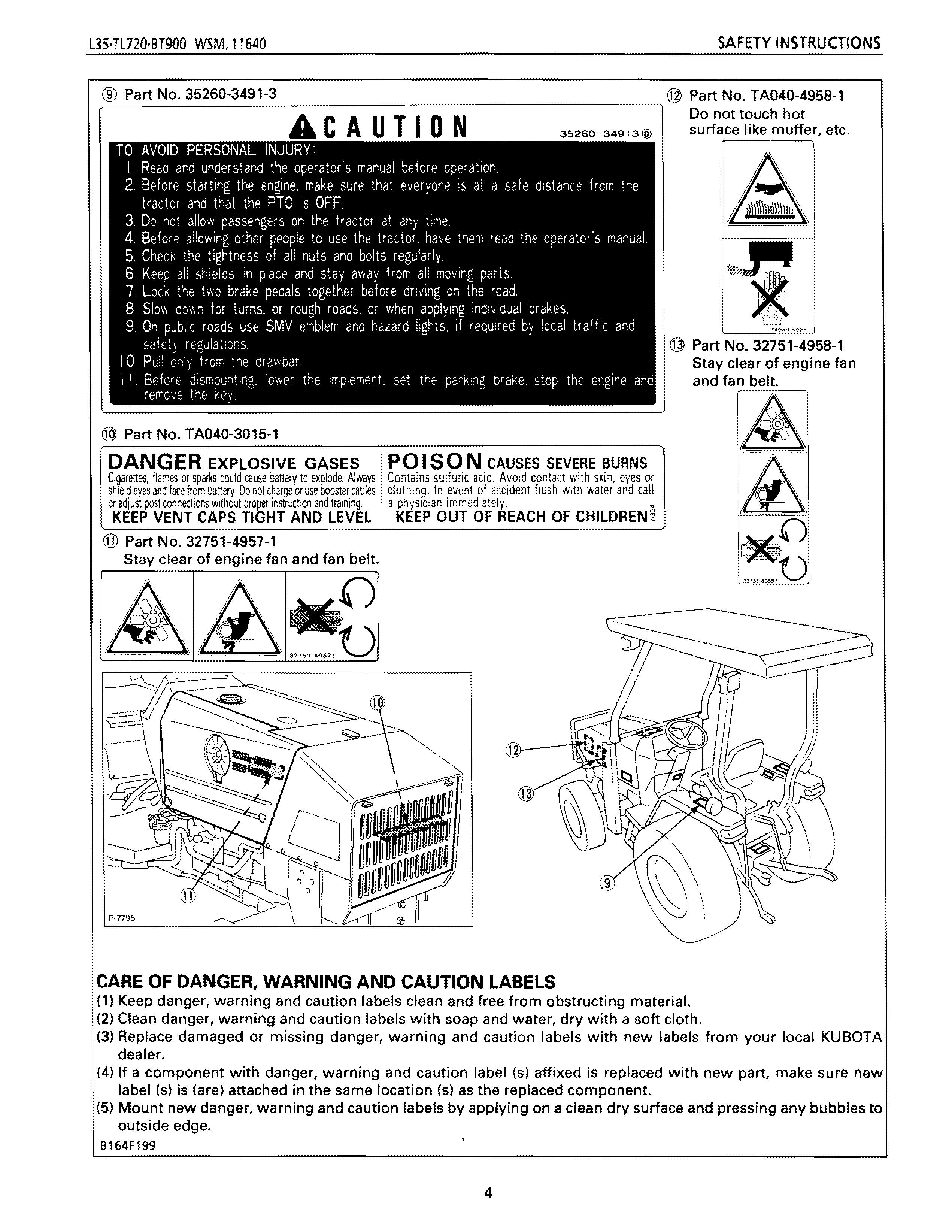
ACAUTION
TO AVOID PERSONAL INJURY:
I. Read and understand the operators manual before operation.
Do not touch hot
35260-34913@ surface like muffer, etc.
2. Before starting the engine. make sure that everyone IS at a safe distance from the tractor and that the PTO is OFF.
3. Do not allow passengers on the tractor at any time
4. Before ailowing other people to use the tractor. have them read the operator'5 manual.
5. Check the tightness of all ruts and bolts regularly.
6. Keep ali shields in place and stay away from all moving parts.
7 Lock the two brake pedals together before driving on the road.
B 51011. down for turns, or rough roads, or when applying individual brakes,
9. On public roads use SMV emblem ana hazard lights, if required by local traHic and safety regulations
10 Pull only from the drawbar
I I. Berore dismounting, lower the Ifnpiement. set the parking brake, stop the engine and remove the key.
®
Part No. TA040-3015-1
DANGER EXPLOSIVE GASES
Cigarettes. flames or sparks could cause battery to explode. Always shield eyes and face from battery. Do not charge or use booster cables or adjust post connections Without prQper jr,struction and training. KEEP VENT CAPS TIGHT AND LEVEL
@ Part No. 32751-4957-1
Stay clear of engine fan and fan belt.
POI SON CAUSES SEVERE BURNS
Contains sulfu,ic acid. Avoid contact with skin, eyes or clothing, In event of accident flush with water and call a physician immediately. • KEEP OUT OF REACH OF CHILDREN 6
@ Part No. 32751-4958-1
Stay clear of engine fan and fan belt.
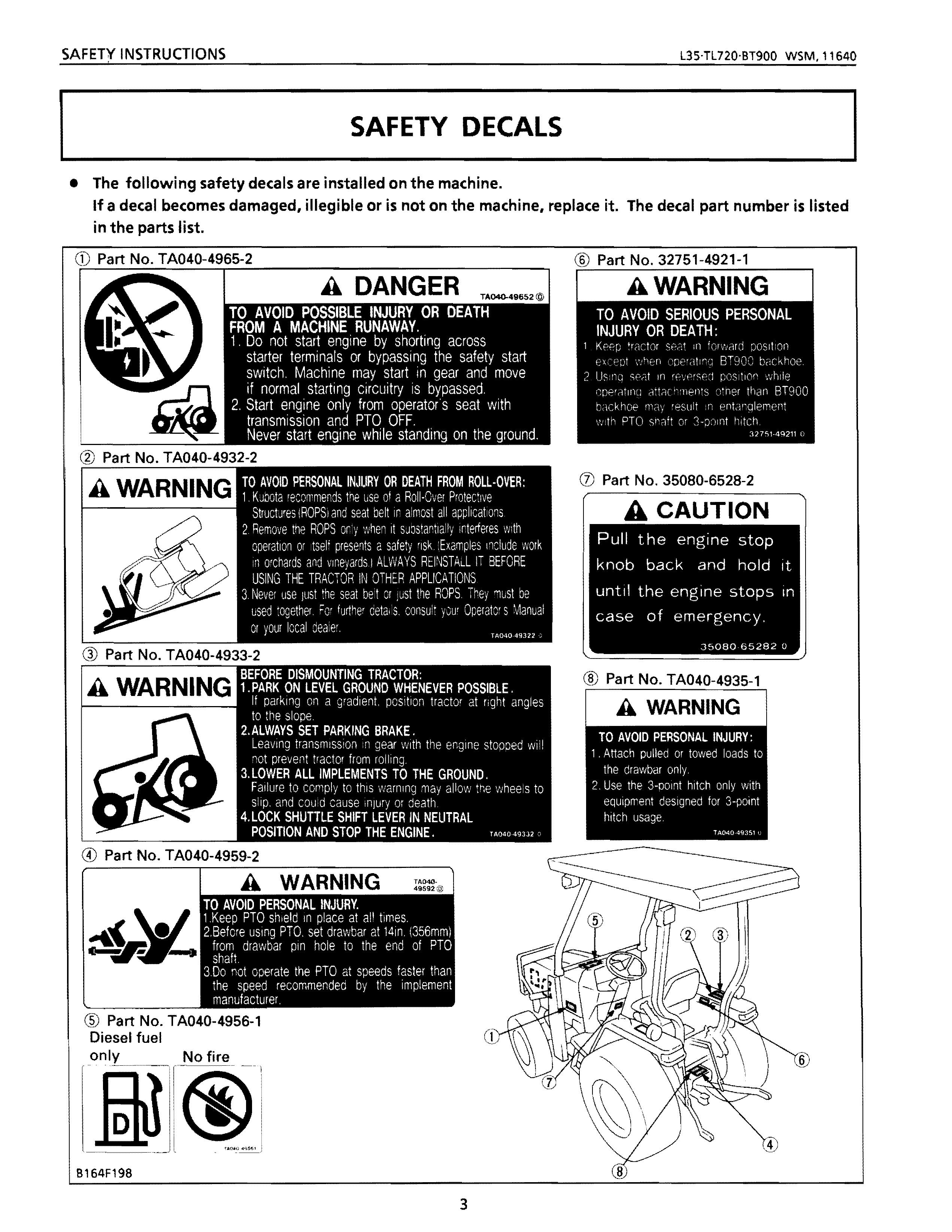
CARE OF DANGER, WARNING AND CAUTION LABELS
(1) Keep danger, warning and caution labels clean and free from obstructing material.
(2) Clean danger, warning and caution labels with soap and water, dry with a soft cloth.
(3) Replace damaged or missing danger, warning and caution labels with new labels from your local KUBOTA dealer.
(4) If a component with danger, warning and caution label (s) affixed is replaced with new part, make sure new label (s) is (are) attached in the same location (s) as the replaced component.
(5) Mount new danger, warning and caution labels by applying on a clean dry surface and pressing any bubbles to outside edge.
B164F199
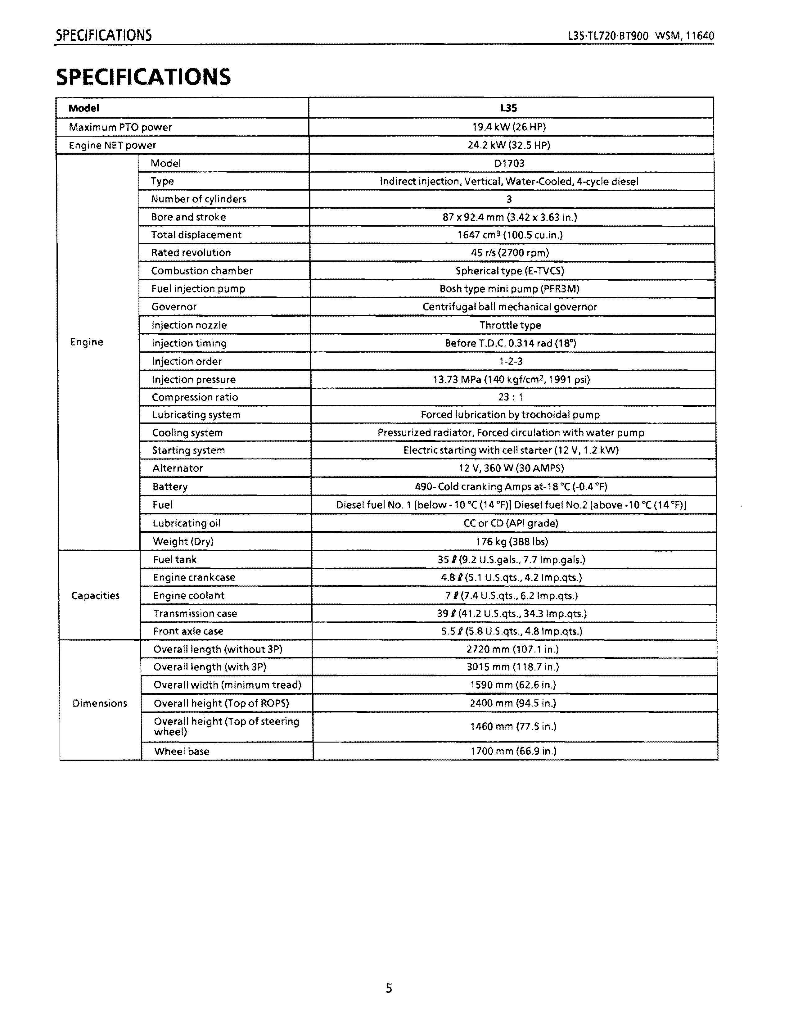
SPECIFICATIONS
Model L35
Maximum PTO power
19.4kW(26HP)
Engine NET power 24.2 kW (32.5 HP)
Model 01703
Type
Indirect injection, Vertical, Water-Cooled, 4-cycle diesel
I Number of cylinders 3
Bore and stroke
87 x92.4 mm (3.42 x 3.63 in.)
Total displacement 1647 cm 3 (100.5 cu.in.)
Rated revolution 45 rls (2700 rpm)
Combustion chamber
Fuel injection pump
Engine
Spherical type (E-TVCS)
Bosh type mini pump (PFR3M)
Governor Centrifugal ball mechanical governor
Injection nozzle Throttle type
Injection timing Before T.D.C. 0.314 rad (18")
Injection order 1-2-3
Injection pressure
13.73 MPa (140 kgf/cm 2 , 1991 psi)
Compression ratio 23: 1
lubricating system
Cooling system
Starting system
Forced lubrication bytrochoidal pump
Pressurized radiator, Forced circulation with water pum p
Electric starting with cell starter (12 V, 1.2 kW)
Alternator 12 V, 360 W (30 AMPS)
Battery 490- Cold cranking Amps at-18°C (-0.4 OF)
Fuel Diesel fuel No.1 [below -10°C (14 OF)] Diesel fuel NO.2 [above·1 0 °c (14 OF)]
lubricating oil
CC or CD (API grade)
Weight (Dry) 176 kg (388Ibs)
Fuel tank
Engine crankcase
Capacities
Engine coolant
Transmission case
Front axle case
Dimensions
351 (9.2 U.S.gals., 7.7Imp.gals.)
4.81 (5.1 U.S.qts., 4.2 Imp.qts.)
71(7.4 U.S.qts., 6.2Imp.qts.)
391 (41.2 U.S.qts., 34.3lmp.qts.)
5.51 (5.8 U.S.qts., 4.8Imp.qts.)
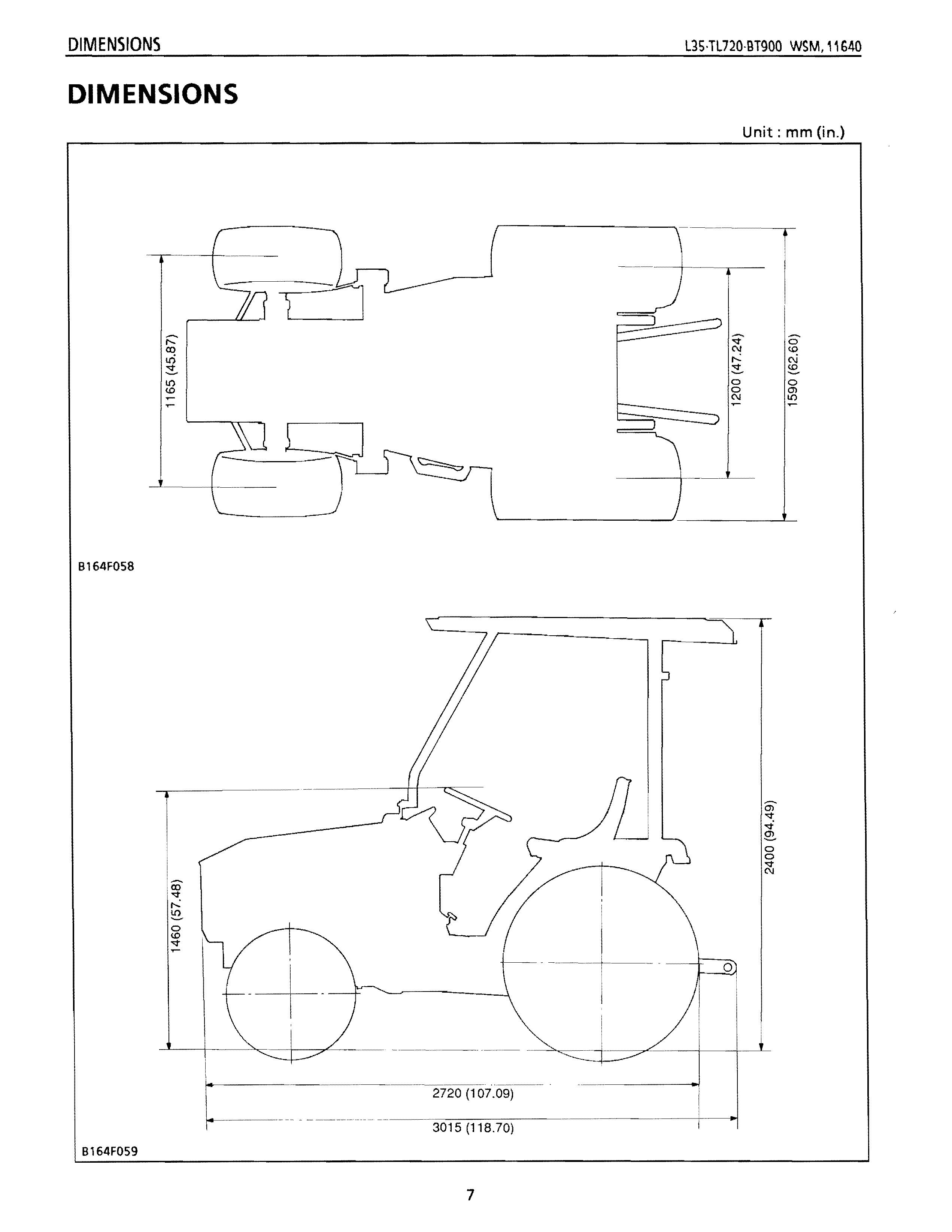
Overall length (without 3P) 2720 mm (107.1 in.)
Overall length (with 3P) 3015 mm (118.7 in.)
Overall width (minimum tread) 1590 m m (62.6 in.)
Overall height (Top of ROPS) 2400 mm (94.5 in.)
Overall height (Top of steering wheel) 1460 mm (77.5 in.)
Wheel base 1700 mm (66.9 in.)
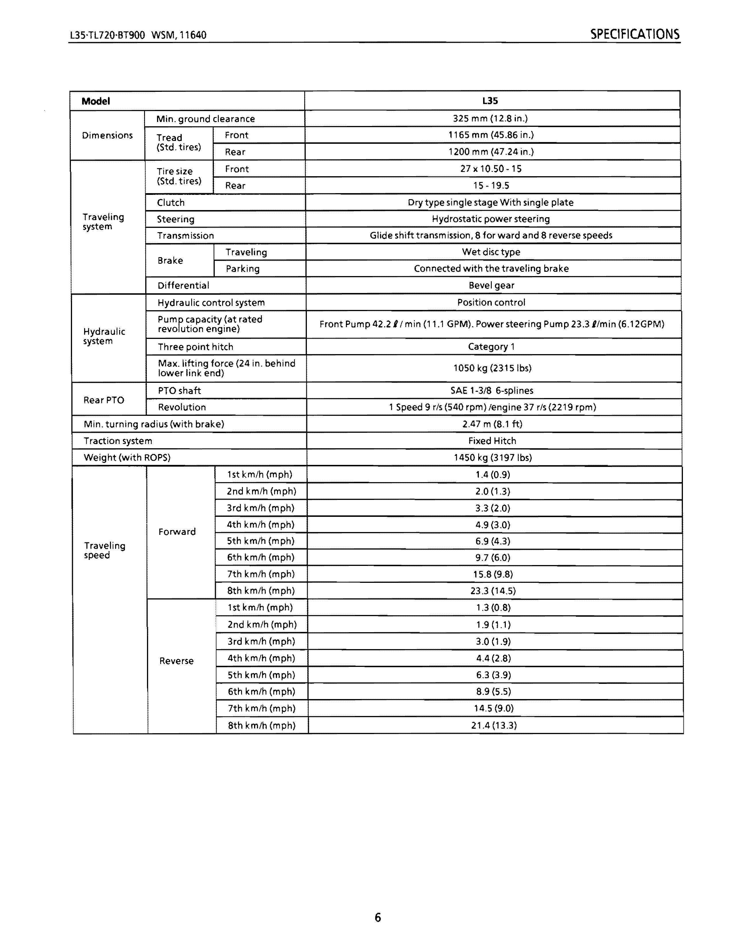
Model
Min. ground clearance
Dimensions Front (Std. tires) Tread Rear
Tire size Front (Std. tires) Rear
Clutch
Traveling Steering system
Transmission Traveling Brake Parking
Differential
Hydraulic control system
pumPt
Hydraulic system
revo ution engine)
Three point hitch
Max. lifting force (24 in. behind lower link end)
PTOshaft
RearPTO
Revolution
Min. turning radius (with brake)
Traction system
Weight (with ROPS)
Traveling
speed
lstkm/h(mph)
2nd km/h (mph)
3rd km/h (mph)
4th km/h (mph) Forward
5th km/h (mph)
6th km/h (mph)
7th km/h (mph)
8th km/h (mph)
1st km/h (mph)
2nd km/h (mph)
3rd km/h (mph)
4th km/h (mph) Reverse
5th km/h (mph)
6th km/h (mph)
7th km/h (mph)
8th km/h (mph)
L35 325 mm (12.S in.)
1165 mm (45.S6 in.)
1200 mm (47.24 in.)
27x 10.50-15
15-19.5
Dry type single stage With single plate
Hydrostatic power steering
Glide shift transmission, S for ward and S reverse speeds
Wet disc type
Connected with the traveling brake
Bevel gear
Position control
Category 1 1050 kg (2315Ibs) SAE 1-3/S 6-splines
1 Speed 9 rls(540 rpm)/engine 37 rls(2219 rpm}
2.47 m (S.l ft)
Fixed Hitch
1450 kg (3197Ibs)
1.4(0.9)
2.0 (1.3)
3.3 (2.0)
4.9 (3.0)
6.9 (4.3)
9.7 (6.0)
15.S (9.S)
23.3 (14.5)
1.3 (O.S)
1.9 (1.1)
3.0 (1.9) 4.4 (2.S) 6.3 (3.9) 8.9 (5.5) 14.5 (9.0) 21.4 (B.3)
DIMENSIONS
Unit: mm (in.)
B164F058
B164F059
CONTENTS
[1] FEATURES
[2] TRACTOR IDENTIFICATION
[3] GENERAL PRECAUTIONS ................................................................................
[4] HANDLING PRECAUTIONS FOR ELECTRICAL PARTS AND WIRING
[5] LUBRICANTS, FUEL AND COOLING WATER
[6] TIGHTENING TORQUES (GENERAL USE SCREWS, BOLTS AND NUTS)
[7] MAINTENANCE CHECK LIST
[8] CHECK AND MAINTENANCE
(1) Daily Check
(2) Check Poi nts of Initial 50 Hours ..............................................................
(3) Check Points of Every 50 Hours
(4) Check Points of Every 100 Hours
(5) Check Poi nts of Every 200 Hou rs
(6) Check Points of Every 400 Hours
(7) Check Poi nts of Every 800 Hours
(8) Check Point of Every 1 Year
(9) Check Point of Every 2 Years
(10) Others
[9] SPECIAL TOOLS
[10] TIRES ............................................................................................................
(1) Tire Pressure
(2) Tread
(3) Wheel Hub
(4) Tire Liquid Injection
[11] SPECIFICATIONS OF IMPLEMENT UMITATIONS
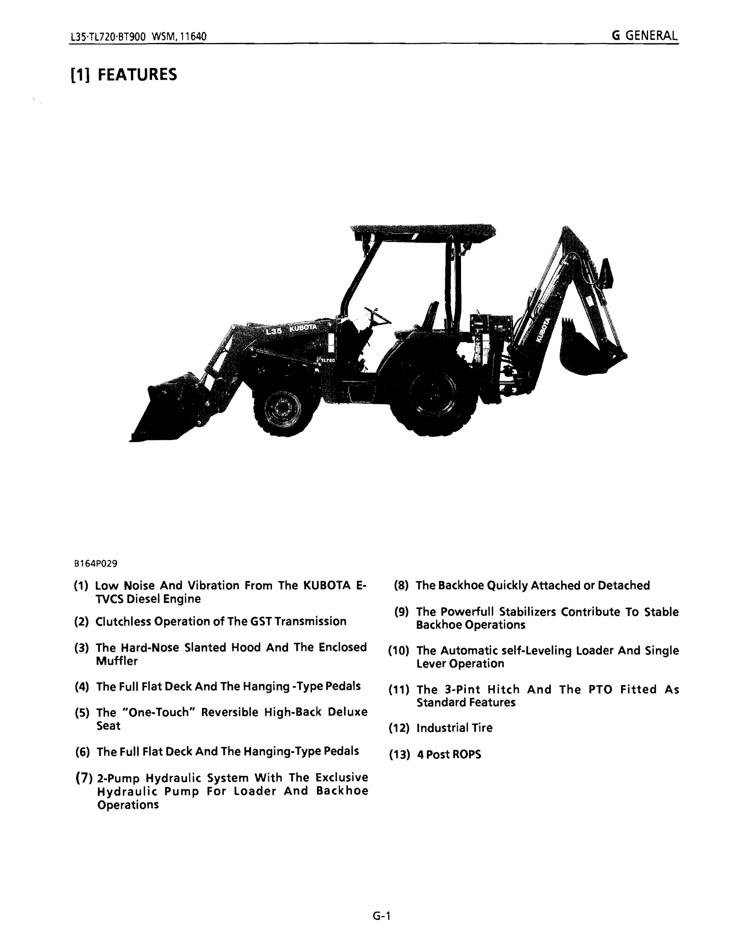
[1] FEATURES
B164P029
(1) Low Noise And Vibration From The KUBOTA ETVCS Diesel Engine
(2) Clutchless Operation of The GST Transmission
(3) The Hard-Nose Slanted Hood And The Enclosed Muffler
(4) The Full Flat Deck And The Hanging -Type Pedals
(5) The "One·Touch" Reversible High-Back Deluxe Seat
(6) The Full Flat Deck And The Hanging-Type Pedals
(7) 2-Pump Hydraulic System With The Exclusive Hydraulic Pump For Loader And Backhoe Operations
(8) The Backhoe Quickly Attached or Detached
(9) The Powerfull Stabilizers Contribute To Stable Backhoe Operations
(10) The Automatic self-Leveling Loader And Single Lever Operation
(11) The 3-Pint Hitch And The PTO Fitted As Standard Features
(12) Industrial Tire
(13) 4 Post ROPS
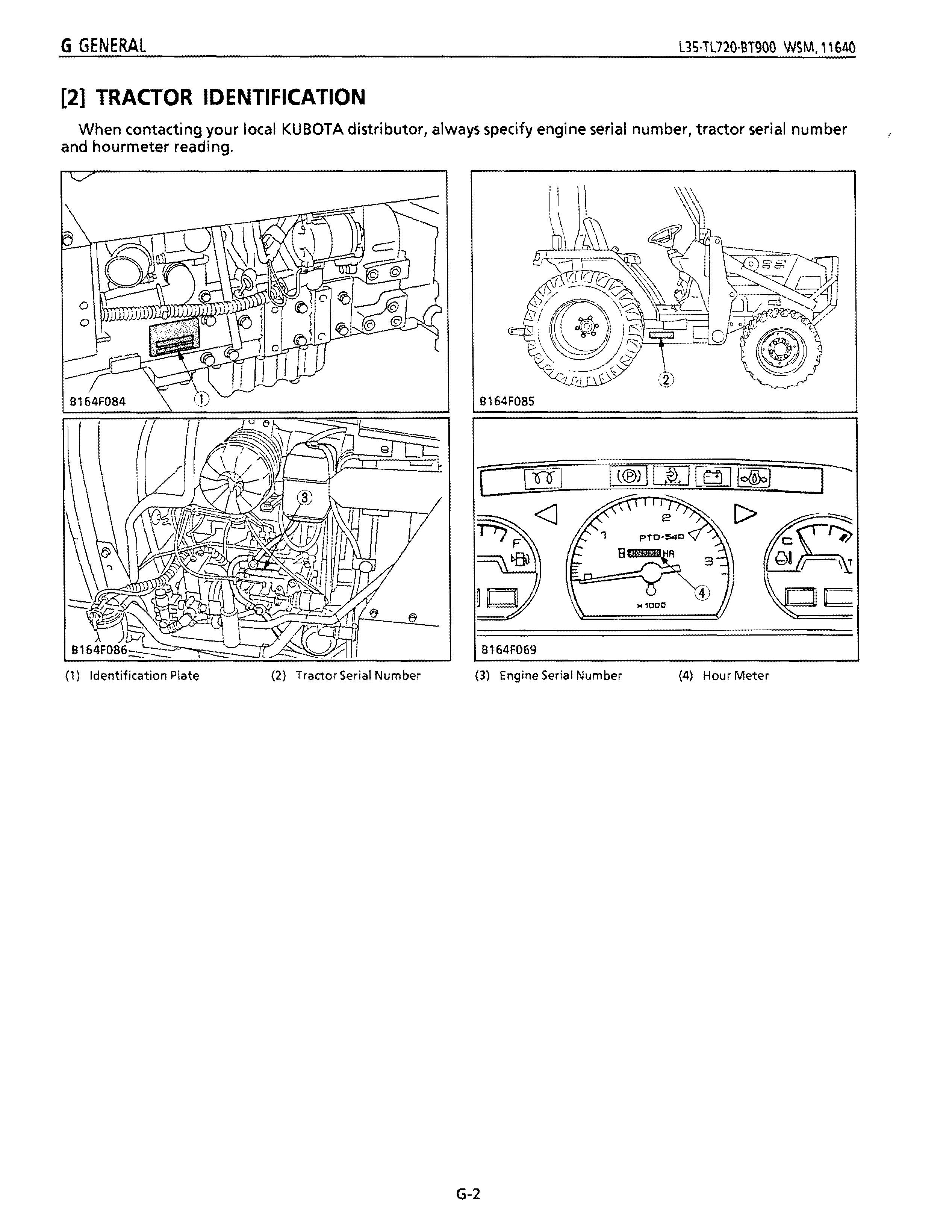
[2] TRACTOR IDENTIFICATION
When contacting your local KUBOTA distributor, always specify engine serial number, tractor serial number and hourmeter reading.
(1) Identification Plate (2) Tractor Serial Number (3) Engine Serial Num ber (4) Hour Meter
B164F085
B164F069
[3] GENERAL PRECAUTIONS
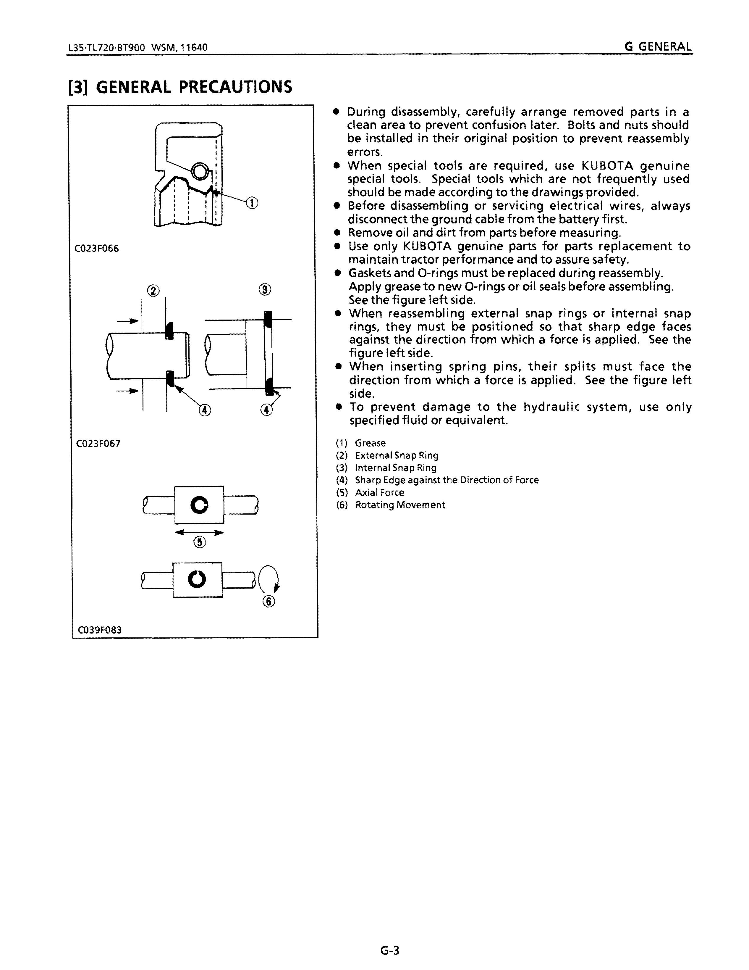
• During disassembly, carefully arrange removed parts in a clean area to prevent confusion later. Bolts and nuts should be installed in their original position to prevent reassembly errors.
• When special tools are required, use KUBOTA genuine special tools. Special tools which are not frequently used should be made according to the drawings provided.
• Before disassembling or servicing electrical wires, always disconnect the ground cable from the battery first.
• Remove oil and dirt from parts before measuring.
• Use only KUBOTA genuine parts for parts replacement to maintain tractor performance and to assure safety_
• Gaskets and O-rings must be replaced during reassembly. Apply grease to new O-rings or oil seals before assembling. See the figure left side.
• When reassembling external snap rings or internal snap rings, they must be positioned so that sharp edge faces against the direction from which a force is applied. See the figure left side.
• When inserting spring pins, their splits must face the direction from which a force is applied. See the figure left side.
• To prevent damage to the hydraulic system, use only specified fluid or equivalent.
(1) Grease
(2) External Snap Ring
(3) Internal Snap Ring
(4) Sharp Edge against the Direction of Force
(5) Axial Force
(6) Rotating Movement
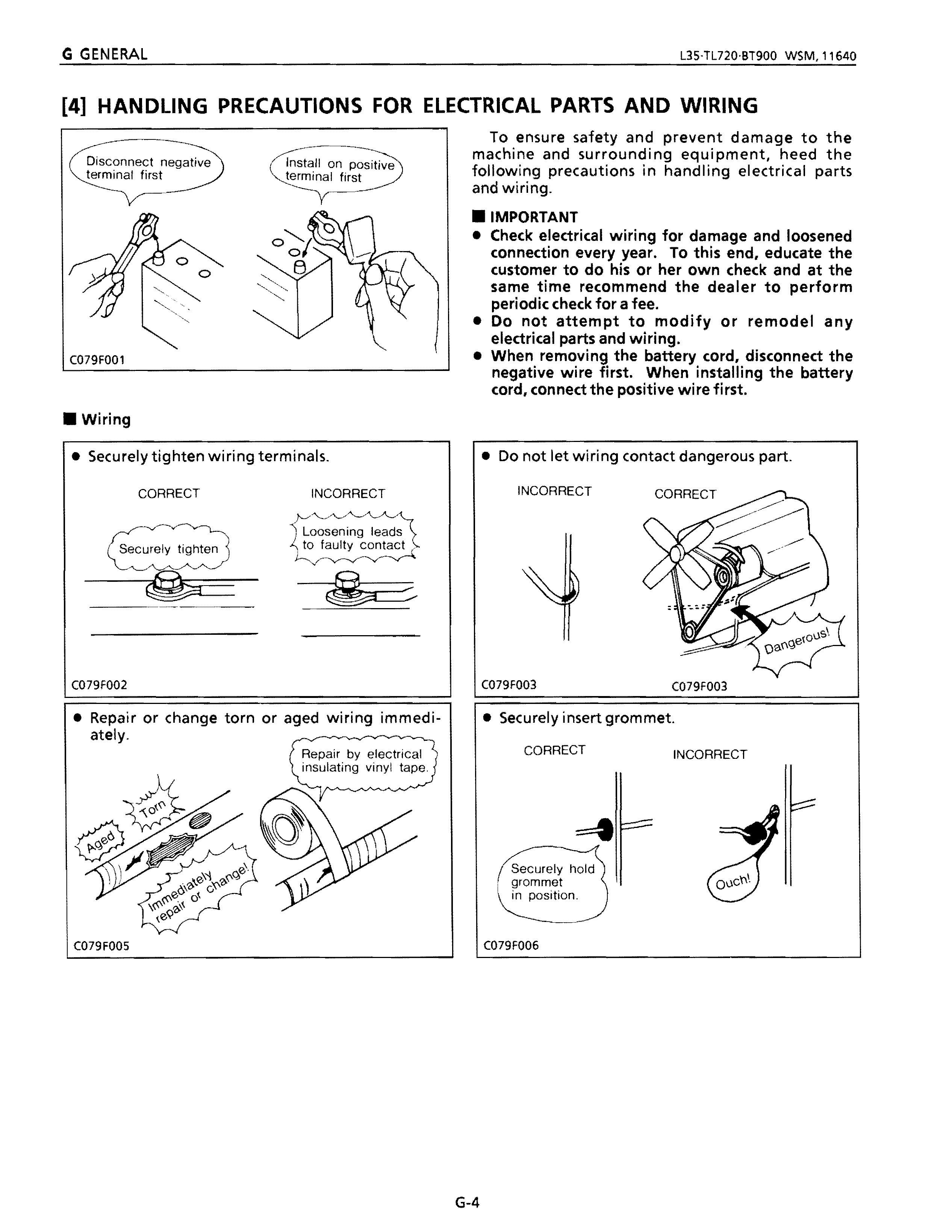
[4] HANDLING PRECAUTIONS FOR ELECTRICAL PARTS AND WIRING
Disconnect n terminal first on positive first
C079F001
• Wiring
• Securely tighten wiring terminals. CORRECT INCORRECT
\::ecurel Y tighten
C079F002
• Repair or change torn or aged wiring immediately. Repair by electrical insulating vinyl tape.
To ensure safety and prevent damage to the machine and surrounding equipment, heed the following precautions in handling electrical parts and wiring
• IMPORTANT
• Check electrical wiring for damage and loosened connection every year. To this end, educate the customer to do his or her own check and at the same time recommend the dealer to perform periodic check for a fee.
• Do not attempt to modify or remodel any electrical parts and wiring.
• When removing the battery cord, disconnect the negative wire first. When installing the battery cord, connect the positive wire first
• INCORRECT
Do not let wiring contact dangerous part CORRECT
• Securely insert grommet CORRECT INCORRECT
Securely hold
I.grommet
C079F005
C079F003
C079F003
C079F006
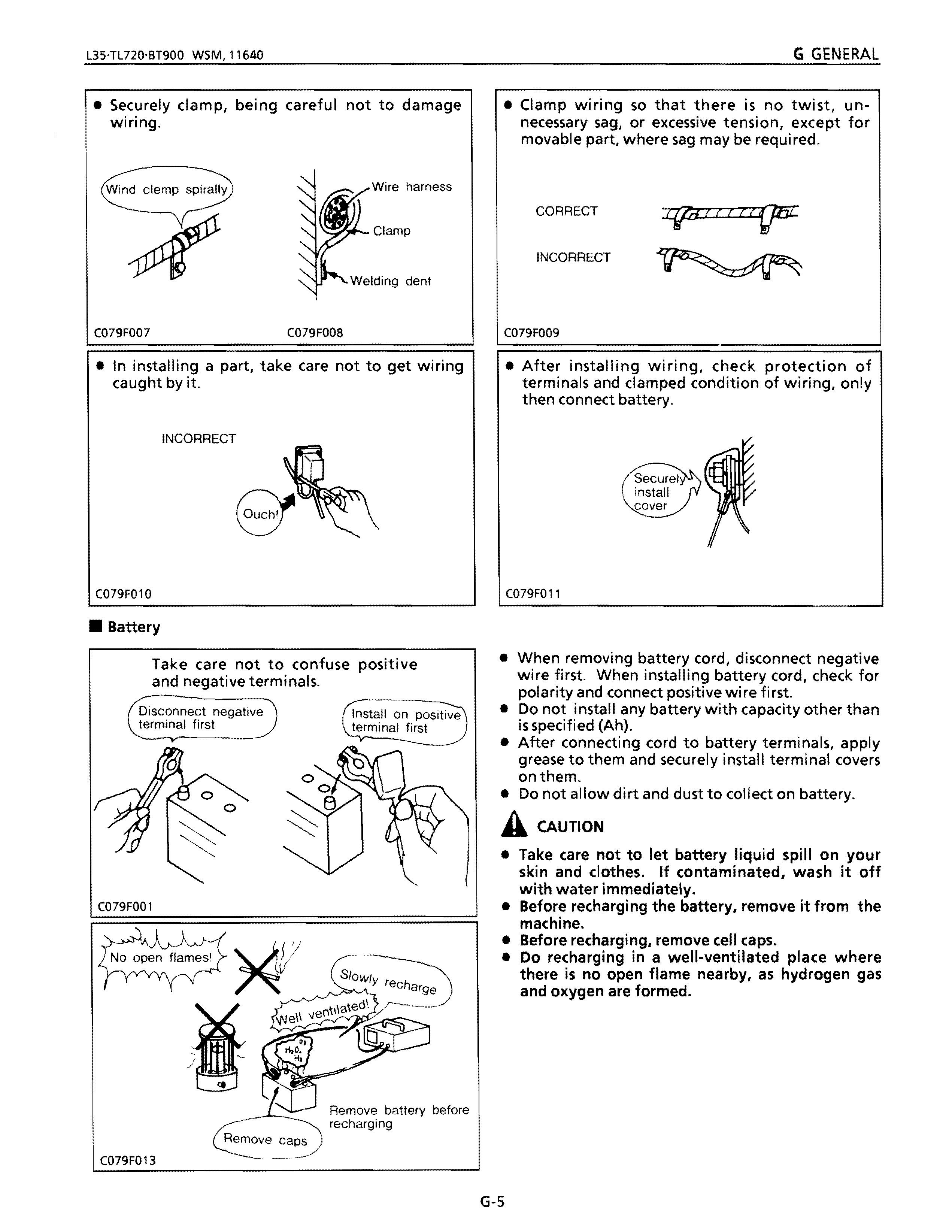
• Securely clamp, being careful not to damage wiring. Wire harness
Wind clemp spirally
C079F007
C079F008
• In installing a part, take care not to get wiring caught by it.
INCORRECT
C079F010
• Battery Take care not to confuse positive and negative terminals.
Disconnect negative terminal first
C079F001
C079F013
• Clamp wiring so that there is no twist, unnecessary sag, or excessive tension, except for movable part, where sag may be required. CORRECT I{fd If I
INCORRECT
C079F009
• After installing wiring, check protection of terminals and clamped condition of wiring, only then connect battery.
C079F011
• When removing battery cord, disconnect negative wire first. When installing battery cord, check for polarity and connect positive wi re fi rst.
• Do not install any battery with capacity other than is specified (Ah).
• After connecting cord to battery terminals, apply grease to them and securely install terminal covers onthem.
• Do not allow dirt and dust to collect on battery.
A CAUTION
• Take care not to let battery liquid spill on your skin and clothes. If contaminated, wash it off with water immediately.
• Before recharging the battery, remove it from the machine.
• Before recharging, remove cell caps.
• Do recharging in a well-ventilated place where there is no open flame nearby, as hydrogen gas and oxygen are formed.
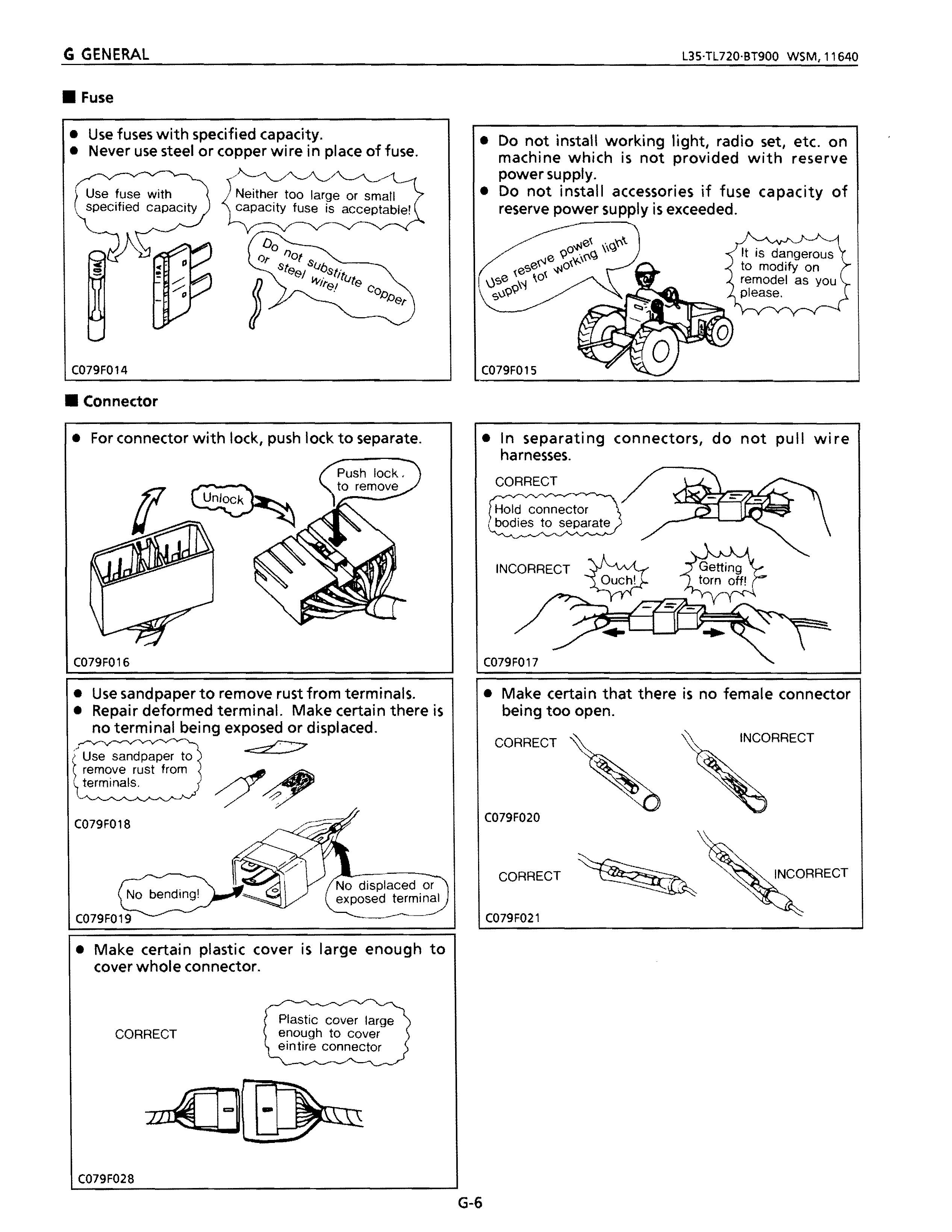
• Fuse
• Use fuses with specified capacity.
• Never use steel or copper wire in place of fuse.
Use fuse with specified capacity Neither too large or small capacity fuse is acceptable!
C079F014
• Connector
• For connector with lock, push lock to separate.
• Do not install working light, radio set, etc. on machine which is not provided with reserve power supply.
• Do not install accessories if fuse capacity of reserve power supply is exceeded.
It is dangerous to modify on remodel as you please.
C079F016
• Use sandpaper to remove rust from terminals.
• Repair deformed terminal. Make certain there is no terminal being exposed or displaced.
Use sandpaper to remove rust from terminals.
C079F01B
No displaced exposed -
• Make certain plastic cover is large enough to cover whole connector.
CORRECT
C079F028
C079F015
• In separating connectors, do not pull wire harnesses.
CORRECT
Hold connector bodies to separate
INCORRECT
C079F017
• Make certain that there is no female connector being too open.
C079F020
CORRECT
C079F021
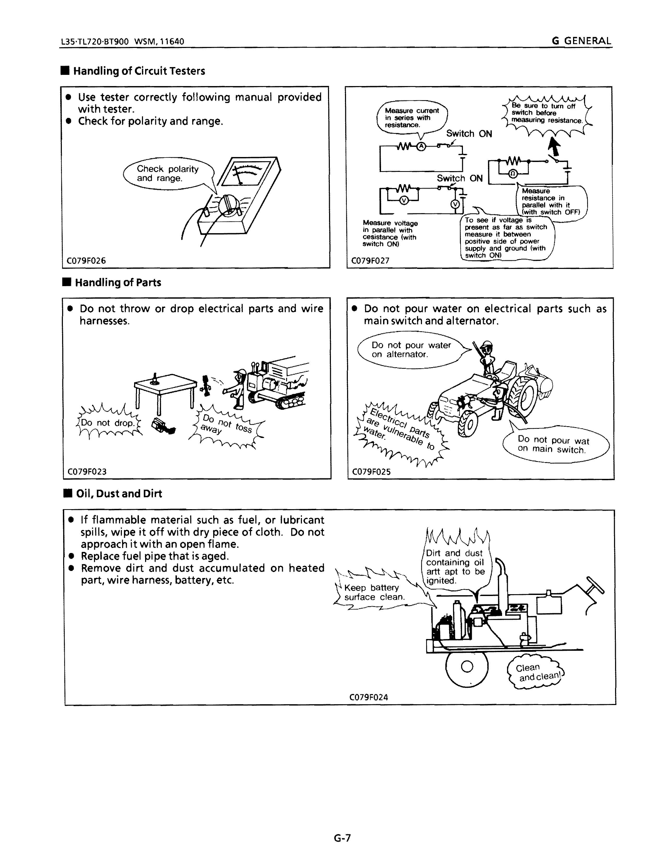
• Handling of Circuit Testers
• Use tester correctly following manual provided with tester
• Check for polarity and range.
Check polarity and range.
C079F026
• Handling of Parts
• Do not throw or drop electrical parts and wire harnesses.
Measure voltage in parallel with cesistance (with switch ON)
C079F027
• Do not pour water on electrical parts such as main switch and alternator.
Do not pour water on alternator.
C079F023
• Oil. Dust and Dirt
• If flammable material such as fuel, or lubricant spills, wipe it off with dry piece of cloth. Do not approach it with an open flame.
• Replace fuel pipe that is aged.
• Remove dirt and dust accumulated on heated part, wire harness, battery, etc.
"Keep battery surface clean.
C079F024
C079F025
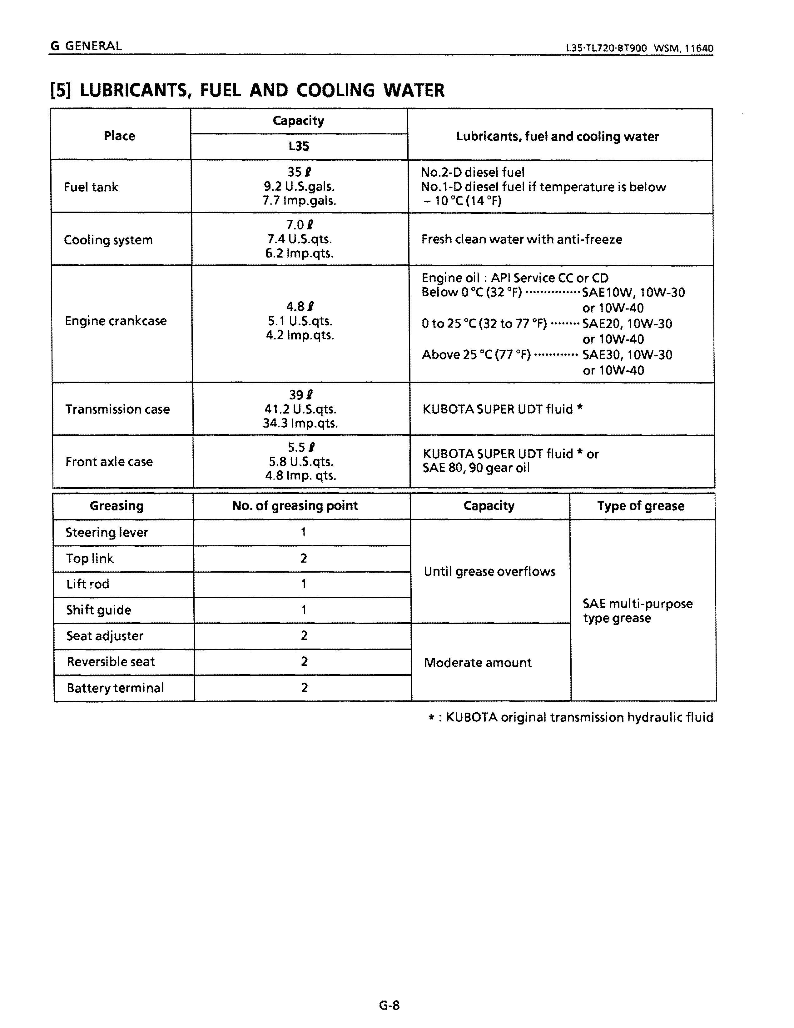
[5] LUBRICANTS, FUEL AND COOLING WATER
Place
Fuel tank
Lubricants. fuel and cooling water L3S
351
9.2 U.S.gais.
No.2-0 diesel fuel
No.1-0 diesel fuel if temperature is below 7.7Imp.gals. -10 °C (14 OF)
7.01
Coo Ii ng system 6.2 Imp.qts.
Engine crankcase
7.4 U.S.qts.
Fresh clean water with anti-freeze
Engine oil: API Service CC or CO
Below 0 °C (32 OF) ···············SAEl OW, 10W-30 4.BI or 10W-40
5.1 U.S.qts. oto 25°C (32 to 77 OF) SAE20, 10W-30
4.2 Imp.qts. or 10W-40
Above 25°C (77 OF) ............ SAE30, 10W-30 or 10W-40
KUBOTA SUPER UOT fluid * or Front axle case 5.B U.S.qts. SAE BO, 90 gear oil 4.Blmp. qts.
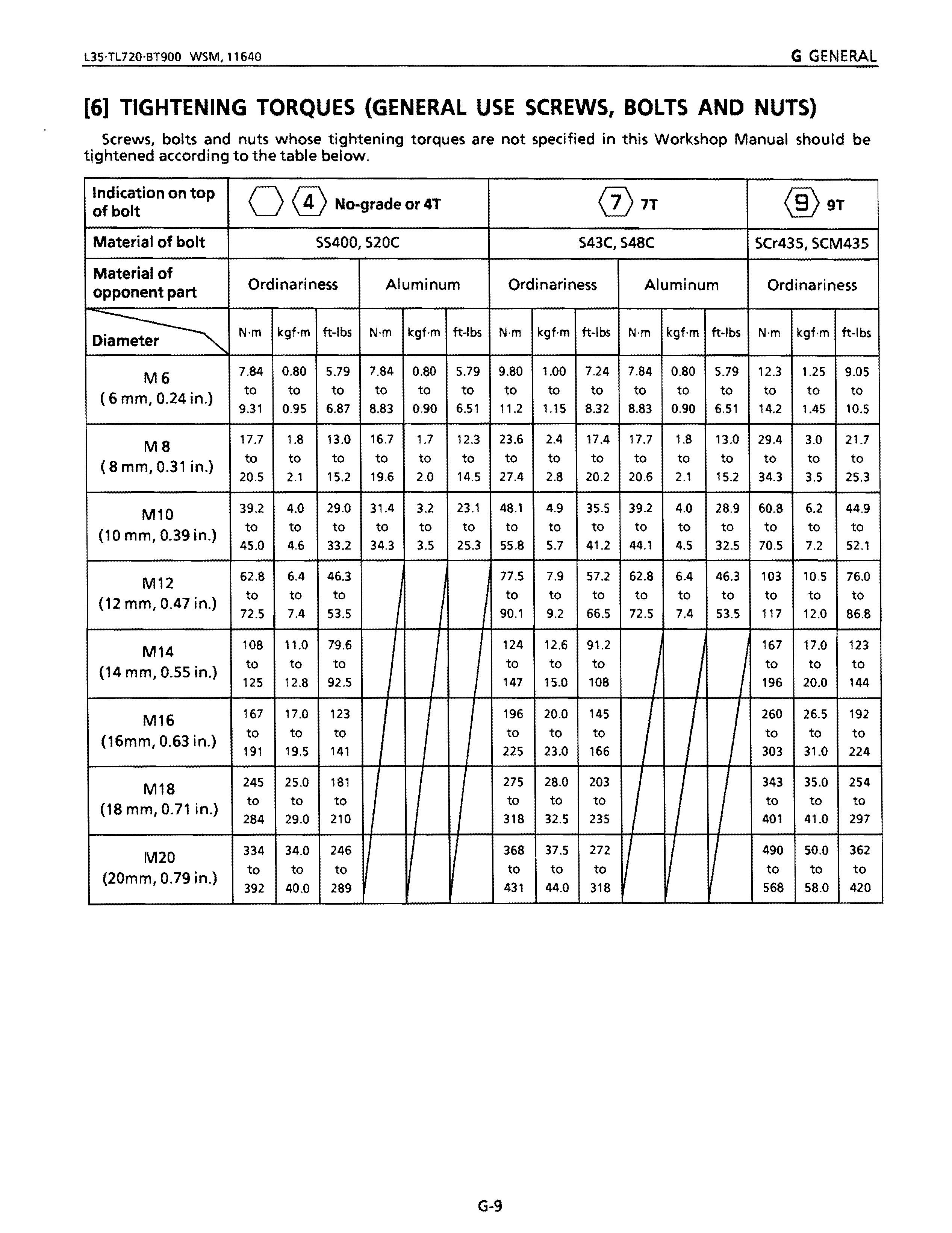
[6] TIGHTENING TORQUES (GENERAL USE SCREWS, BOLTS AND NUTS)
Screws, bolts and nuts whose tightening torques are not specified in this Workshop Manual should be tightened according to the table below.
Indication on top of bolt
Material of bolt
Material of opponent part
M6 ( 6 mm, 0.24 in.)
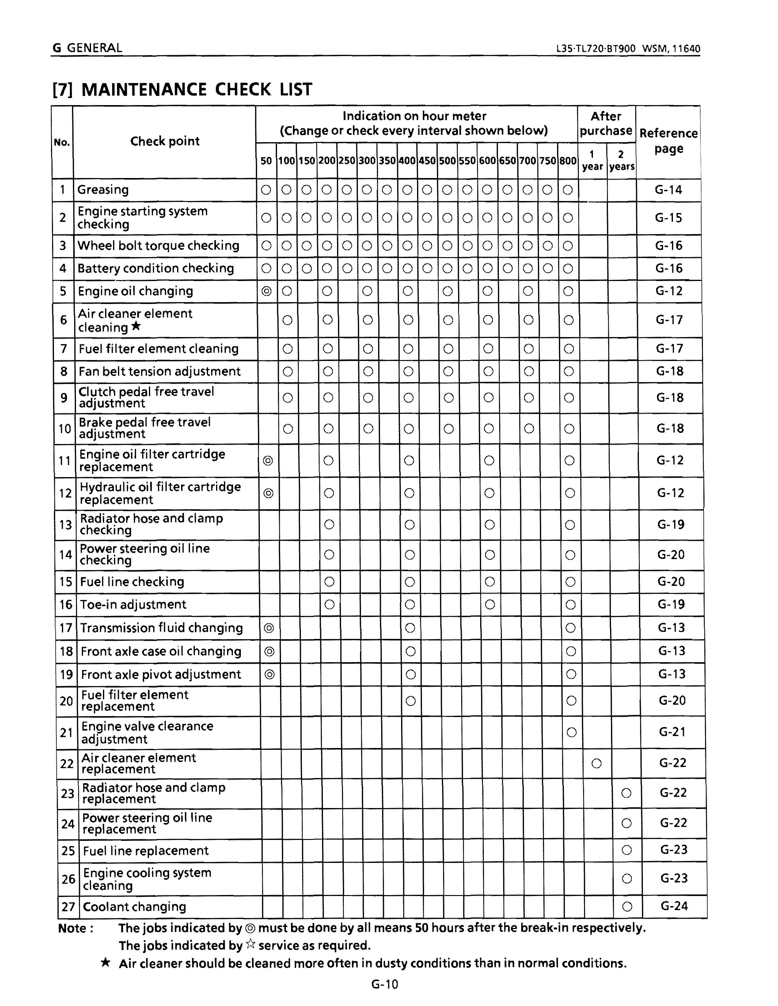
[7] MAINTENANCE CHECK LIST
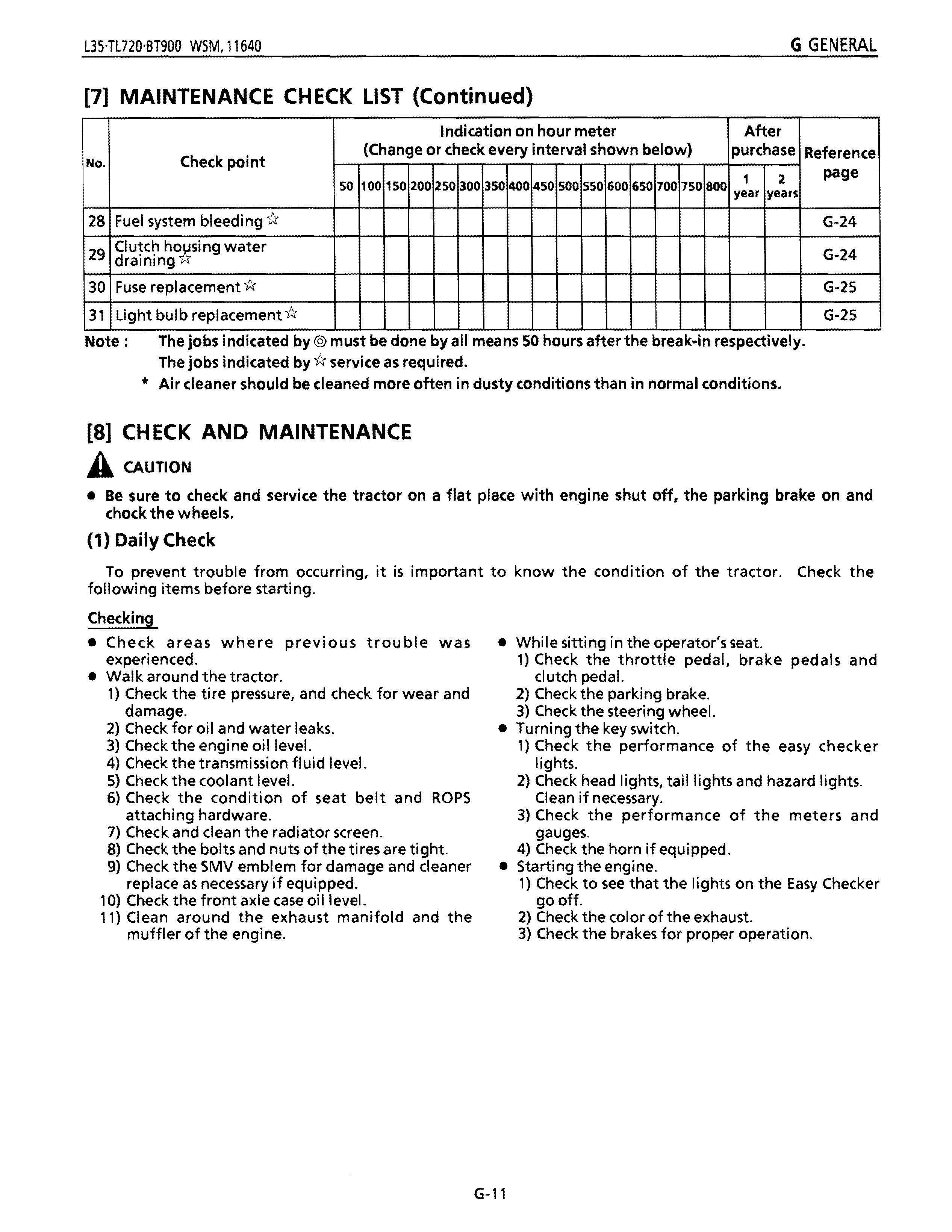
[7] MAINTENANCE CH ECK LIST (Continued)
or check every interval shown below)
30 Fuse replacement 1:!
31 Light bulb replacement u
Note: The jobs indicated by@ must be done by all means 50 hours after the break-in respectively. The jobs indicated by u service as required
Air deaner should be deaned more often in dusty conditions than in normal conditions.
[8] CH ECK AND MAINTENANCE
A CAUTION
• Be sure to check and service the tractor on a flat place with engine shut off. the parking brake on and chock the wheels.
(1) Daily Check
To prevent trouble from occurring, it is important to know the condition of the tractor. Check the following items before starting.
Checking
• Check areas where previous trouble was experienced.
• Walk around the tractor.
1) Check the tire pressure, and check for wear and damage.
2) Check for oil and water leaks.
3) Check the engine oil level.
4) Check the transmission fluid level.
5) Check the coolant level.
6) Check the condition of seat belt and ROPS attaching hardware.
7) Check and dean the radiator screen.
8) Check the bolts and nuts of the ti res are tight.
9) Check the SMV emblem for damage and cleaner replace as necessary if equipped.
10) Check the front axle case oil level.
11) Clean around the exhaust manifold and the muffler of the engine.
• While sitting in the operator's seat.
1) Check the throttle pedal, brake pedals and cI utch pedal.
2) Check the parking brake.
3) Check the steering wheel.
• Turning the key switch.
1) Check the performance of the easy checker lights.
2) Check head lights, tail lights and hazard lights. Clean if necessary.
3) Check the performance of the meters and gauges.
4) Check the horn if equipped.
• Starting the engine.
1) Check to see that the lights on the Easy Checker go off.
2) Check the color of the exhaust.
3) Check the brakes for proper operation.
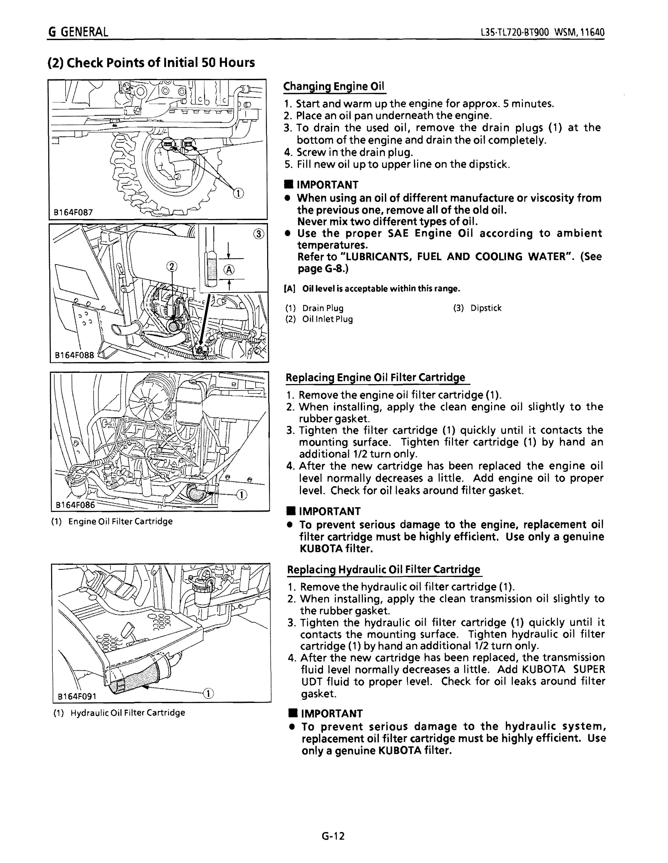
(2) Check Points of Initial 50 Hours
Changing
Engine Oil
1. Start and warm up the engine for approx. 5 minutes.
2. Place an oil pan underneath the engine.
3. To drain the used oil, remove the drain plugs (1) at the bottom of the engine and drain the oil completely.
4. Screw in the drain plug.
5. Fill new oil upto upper line on the dipstick .
• IMPORTANT
• When using an oil of different manufacture or viscosity from the previous one, remove all of the old oil. Never mix two different types of oil.
• Use the proper SAE Engine Oil according to ambient temperatures.
Refer to "LUBRICANTS, FUEL AND COOLING WATER". (See pageG-8.)
(AI Oil level is acceptable within this range.
(1) Drain Plug (3) Dipstick (2) Oil Inlet Plug
Replacing Engine Oil Filter Cartridge
1. Remove the engine oil filter cartridge (1).
2. When installing, apply the clean engine oil slightly to the rubber gasket.
3. Tighten the fj Iter cartridge (1) quickly u nti I it contacts the mounting surface. Tighten filter cartridge (1) by hand an additional 1/2 turn only.
4. After the new cartridge has been replaced the engine oil level normally decreases a little. Add engine oil to proper level. Check for oil leaks around filter gasket
• IMPORTANT
• To prevent serious damage to the engine, replacement oil filter cartridge must be highly efficient. Use only a genuine KUBOTA filter.
Replacing Hydraulic Oil Filter Cartridge
1. Remove the hydraulic oil filter cartridge (1).
2. When installing, apply the clean transmission oil slightly to the rubber gasket.
3. Tighten the hydraulic oil filter cartridge (1) quickly until it contacts the mounting surface. Tighten hydraulic oil filter cartridge (1) by hand an additional 1/2 turn only.
4. After the new cartridge has been replaced, the transmission fluid level normally decreases a little. Add KUBOTA SUPER UDT fluid to proper level. Check for oil leaks around filter gasket.
• IMPORTANT
• To prevent serious damage to the hydraulic system, replacement oil filter cartridge must be highly efficient. Use only a genuine KUBOTA filter.
(1) Engine Oil Filter Cartridge
(1) Hydraulic Oil Filter Cartridge
Changing Transmission Fluid
1. Place the oi I pans underneath the transmission case.
2. Remove the four drain plugs (1) to drain transmission fluid.
3. Screw in the drain plugs (1).
4. Remove the oil filling plug (2).
S. Fill new transmission fluid up to the upper line on the dipstick (3).
6. Reinstall the oil filling plug (2).
7. After running the engine for few minutes, stop it and check the oil level again. If low, add new fluid
• IMPORTANT
• Use only KUBOTA SUPER UDT fluid. Use of other oils may damage the transmission or hydraulic system. Refer to "LUBRICANTS, FUEL AND COOLING WATER". (See page G-8.)
• Never work the tractor immediately after changing the transmission fluid. Keeping the engine at medium speed for a few minutes to prevents damage to the transmission.
(AI Oil level is acceptable within this range.
(1) Drain Plug (3) Dipstick (2) Filling Plug
Changing Front Axle Case Oil
1. Place the oil pans underneath the front axle case.
2. Remove the drain plug (1) both sides and filling port plug (3) to drain the oil.
3. After draining, reinstall the drain plugs (1).
4. Remove the oil level check plug (2).
S. Fill new oil up to the check plug (2) port.
6. After filling, reinstall the check plug (2) and filling port plug (3) .
• IMPORTANT
• Use KUBOTA SUPER UDTfluid or SAE SO, 90 gear oil. Refer to "LUBRICANTS, FUEL AND COOLING WATER". (See page G-8.)
(1) Drain Plug (3) Filling Port Plug (2) Check Plug
Adjusting Front Axle Pivot
1. Loosen the lock nut (2), tighten the adjusting screw (1) all the way, and then loosen the adjusting screw (1) by 1/6turn.
2. Retighten the lock nut (2).
(1) Adjusting Screw (2) Lock Nut
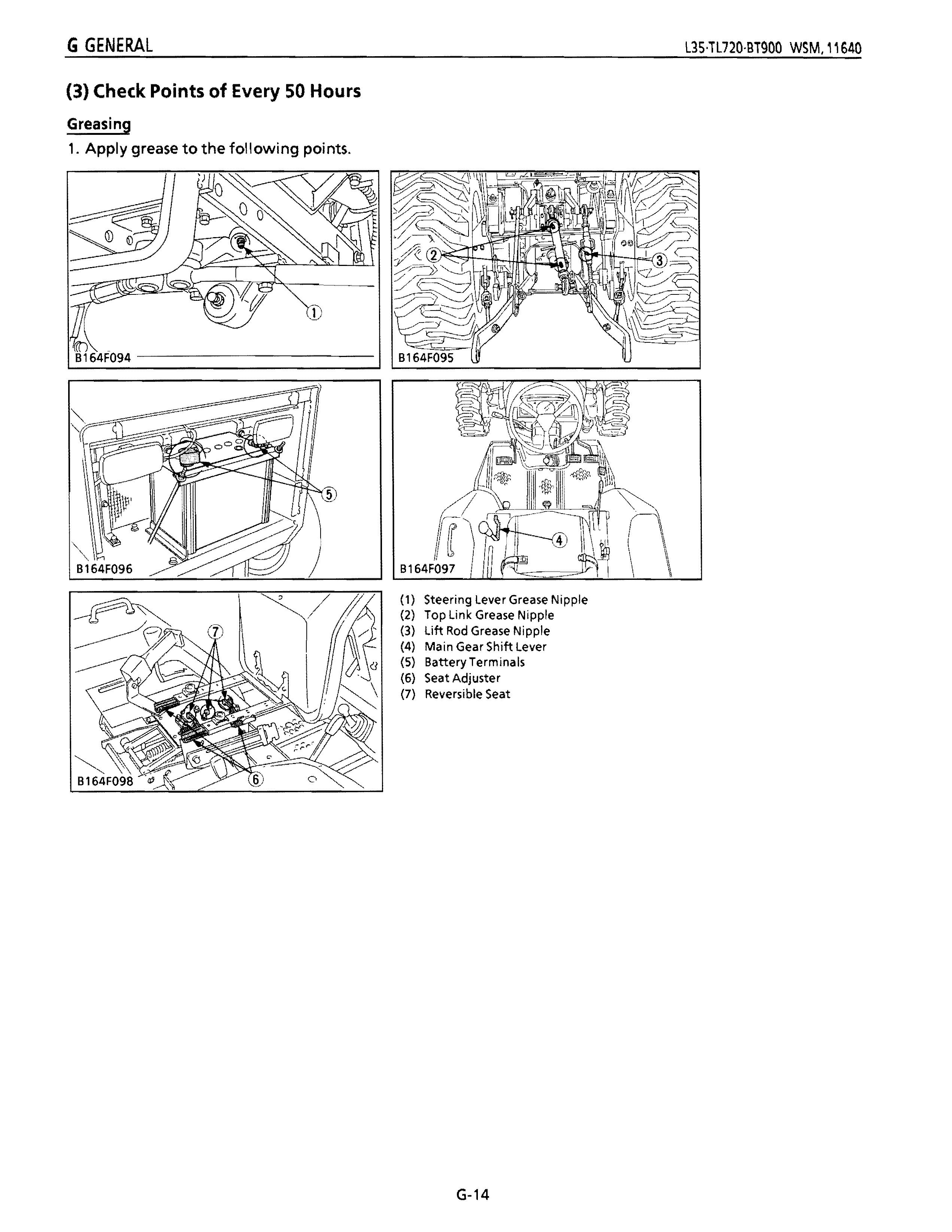
(3) Check Points of Every 50 Hours
Greasing
1. Apply grease to the following points.
(1) Steering lever Grease Nipple (2) Top link Grease Nipple (3) lift Rod Grease Nipple (4) Main Gear Shift lever (5) Battery Terminals (6) Seat Adjuster (7) Reversible Seat
Checking Engine Starting System
A
CAUTION
• Do not allow anyone near the tractor while testing.
• If the tractor does not pass the test do not operate the tractor.
• Preparation
1. Place the all control levers in the "NEUTRAL" position.
2. Set the parking brake and stop the engine.
• Test 1 : Limit Switch of Built-in PTO Shift Lever
1. Sit on operator's seat.
2. Engage the PTO shift lever (3).
3. Depress the clutch pedal (2) fully.
4. Shift the shuttle shift lever (1) to the neutral position.
5. Pull out the engine stop knob and turn the key to "START" position.
6. The engine must not crank.
7. If crank, repair or replace the PTO Ii mit switch or starter relay.
• Test 2: Limit Switch of Built-in Shuttle Shift Lever
1. Sit on operator's seat.
2. Shift the shuttle shift lever (1) to the forward or reverse position.
3. Depress the clutch pedal (2) fully.
4. Disengage the PTO shift lever (3).
5. Pull out the engine stop knob and turn the key to "START" position.
6. The engine must not crank.
7. If crank, repair or replace the shuttle limit switch or starter relay.
Checking Battery Condition
A CAUTION
• Never remove the vent plugs (3) while the engine is running.
• Keep electrolyte away from eyes, hands and clothes. If you are spattered with it, wash it away completely with water immediately and get medical attention.
• Wear eye protection and rubber gloves when working around battery.
• NOTE
• The original battery is maintenance free type battery, but need some servicing.
• Howto Read the Indicator
• Ifthe indicator (2) is blue color. Specific gravity of electrolyte and quantity of electrolyte are both in good condition.
• Ifthe indicator (2) is white color
Need inspection:
CD Add only distilled water if the electrolyte level is low. (Proper level is shown in the figure left)
You can start work again if the indicator display turns to
blue.
Change battery if the indicator display remains white.
® Change battery if the electrolyte level is normal.
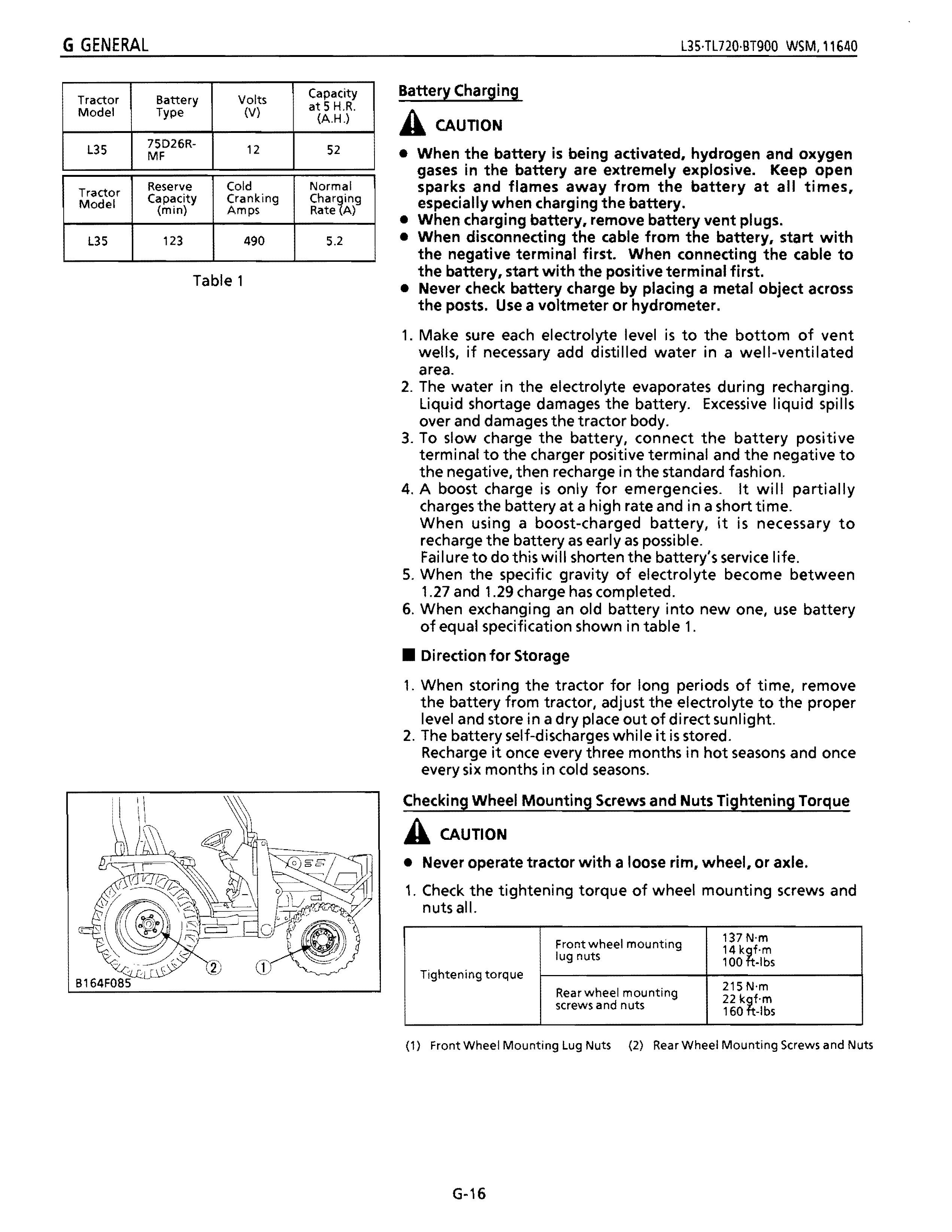
Tractor Reserve Cold Normal Model Capacity Cranking (min) Amps Rate A) L35 123 490 5.2 Table 1
Battery Charging
ACAUTION
• When the battery is being activated, hydrogen and oxygen gases in the battery are extremely explosive. Keep open sparks and flames away from the battery at all times, especially when charging the battery.
• When charging battery, remove battery vent plugs.
• When disconnecting the cable from the battery, start with the negative terminal first. When connecting the cable to the battery, start with the positive terminal first.
• Never check battery charge by placing a metal object across the posts. Use a voltmeter or hydrometer.
1. Make sure each electrolyte level is to the bottom of vent wells, if necessary add distilled water in a well-ventilated area.
2. The water in the electrolyte evaporates during recharging. Liquid shortage damages the battery. Excessive liquid spills over and damages the tractor body.
3. To slow charge the battery, connect the battery positive terminal to the charger positive terminal and the negative to the negative, then recharge in the standard fashion.
4. A boost charge is only for emergencies. It will partially charges the battery at a high rate and in a short time. When using a boost-charged battery, it is necessary to recharge the battery as early as possible. Failure to do this will shorten the battery's service life.
5. When the specific gravity of electrolyte become between 1.27 and 1.29 charge has completed.
6. When exchanging an old battery into new one, use battery of equal specification shown in table 1.
• Direction for
Storage
1. When storing the tractor for long periods of time, remove the battery from tractor, adjust the electrolyte to the proper level and store in a dry place out of direct sunlight.
2. The battery self-discharges while it is stored. Recharge it once every three months in hot seasons and once every six months in cold seasons.
Checking wheel Mounting Screws and Nuts Tightening Torque
ACAUTION
• Never operate tractor with a loose rim, wheel, or axle.
1. Check the tightening torque of wheel mounting screws and nuts all.
Tightening torque
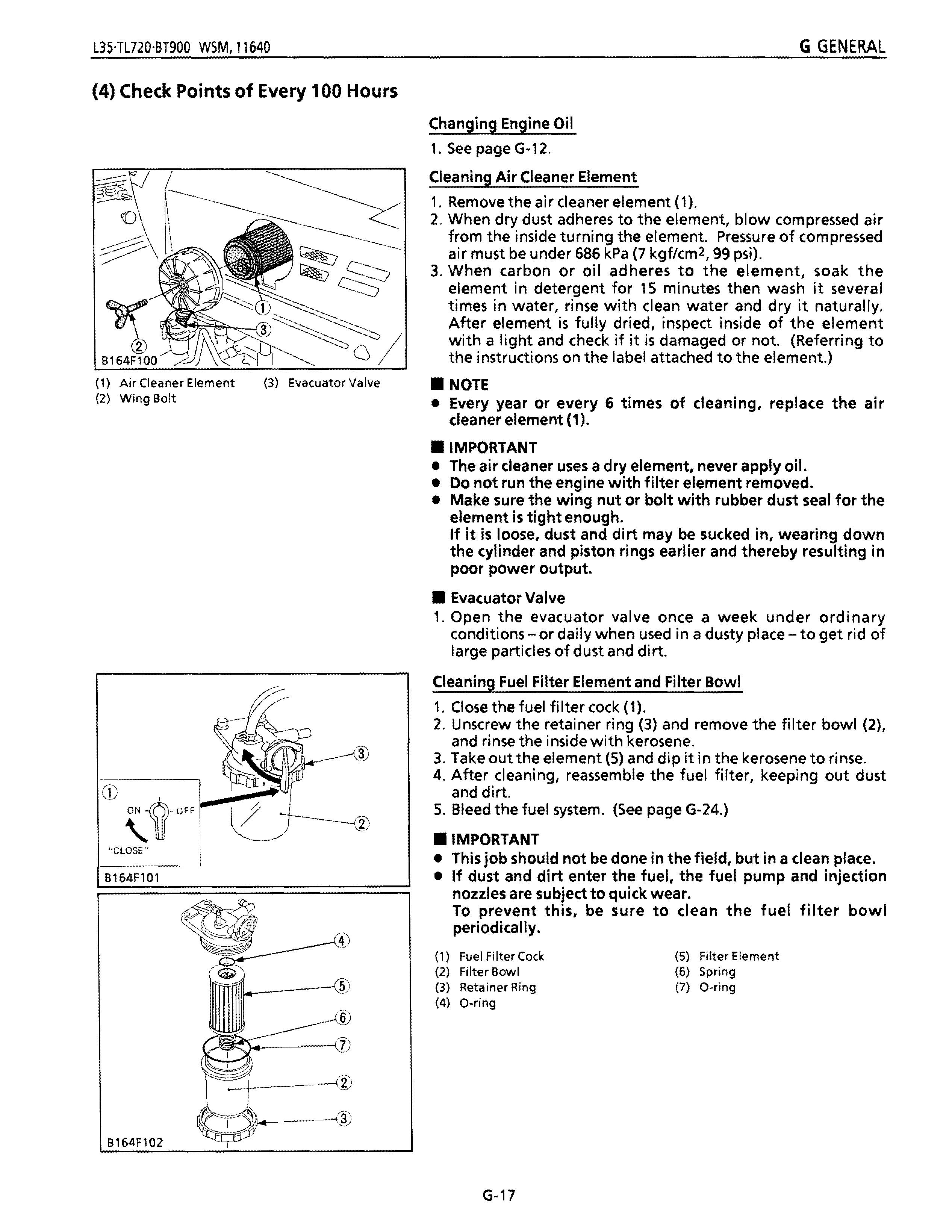
(4) Check Points of Every 100 Hours
(1) Air Cleaner Element (3) Evacuator Valve (2) Wing Bolt
Changing Engine Oil
1. See page Gw12.
Cleaning Air Cleaner Element
1. Remove the air cleaner element (1).
2. When dry dust adheres to the element, blow compressed air from the inside turning the element. Pressure of compressed air must be under 686 kPa (7 kgf/cm 2 , 99 psi).
3. When carbon or oil adheres to the element, soak the element in detergent for 15 minutes then wash it several times in water, rinse with clean water and dry it naturally. After element is fully dried, inspect inside of the element with a light and check if it is damaged or not. (Referring to the instructions on the label attached to the element.)
• NOTE
• Every year or every 6 times of cleaning, replace the air cleaner element (1) .
• IMPORTANT
• The air cleaner uses a dry element, never apply oil.
• Do not run the engine with filter element removed.
• Make sure the wing nut or bolt with rubber dust seal for the element is tight enough. If it is loose, dust and dirt may be sucked in, wearing down the cylinder and piston rings earlier and thereby resulting in poor power output.
• Evacuator Valve
1. Open the evacuator valve once a week under ordinary conditions - or daily when used in a dusty place - to get rid of large particles of dust and dirt.
Cleaning Fuel Filter Element and Filter Bowl
1. Close the fuel filter cock (1).
2. Unscrew the retainer ring (3) and remove the filter bowl (2), and rinse the inside with kerosene.
3. Take out the element (5) and dip it in the kerosene to rinse.
4. After cleaning, reassemble the fuel filter, keeping out dust and dirt.
5. Bleed the fuel system. (See page Gw24.)
• IMPORTANT "CLOSE"
B164Fl0l
• This job should not be done in the field, but in a clean place.
• If dust and dirt enter the fuel, the fuel pump and injection
nozzles are subject to quick wear.
To prevent this, be sure to clean the fuel filter bowl
periodically.
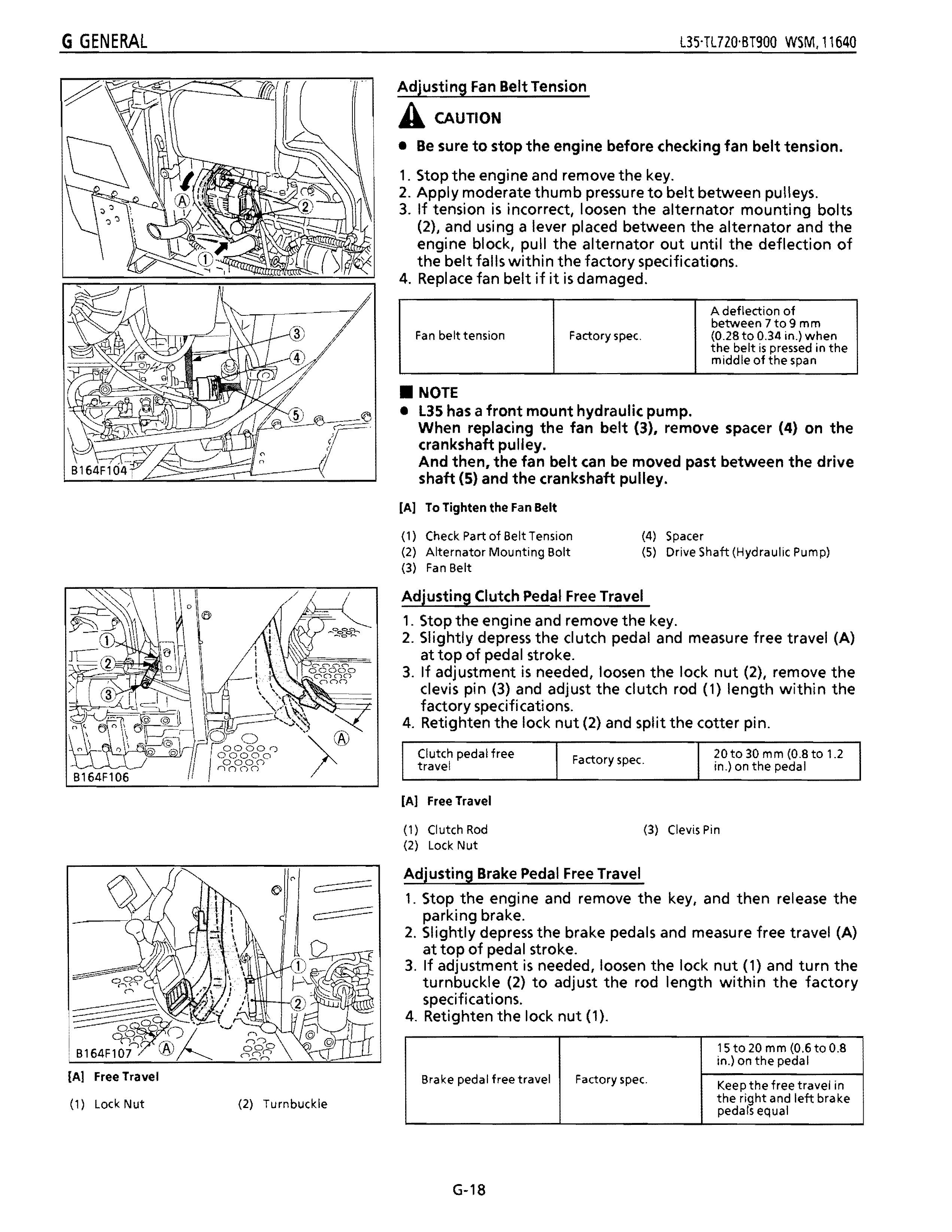
Adjusting Fan Belt Tension
ACAUTION
• Be sure to stop the engine before checking fan belt tension.
1. Stop the engine and remove the key.
2. Apply moderate thumb pressure to belt between pulleys.
3. If tension is incorrect, loosen the alternator mounting bolts (2), and using a lever placed between the alternator and the engine block, pull the alternator out until the deflection of the belt falls within the factory specifications.
4. Replace fan belt if it is damaged.
• NOTE
• l35 has a front mount hydraulic pump. When replacing the fan belt (3), remove spacer (4) on the crankshaft pUlley.
And then, the fan belt can be moved past between the drive shaft (5) and the crankshaft pulley.
[A] To Tighten the Fan Belt
(1) Check Part of Belt Tension
(2) Alternator Mounting Bolt
(4)
(3) Fan Belt (5) Spacer Drive Shaft (Hydraulic Pump)
Adjusting Clutch Pedal Free Travel
1. Stop the engine and remove the key.
2. Slightly depress the clutch pedal and measure free travel (A) at top of pedal stroke.
3. If adjustment is needed, loosen the lock nut (2), remove the clevis pin (3) and adjust the clutch rod (1) length within the factory specifications.
4. Retighten the lock nut (2) and split the cotter pin.
Clutch pedal free 20 to 30 mm (0.8 to 1.2 Factory spec. travel in.) on the pedal
A deflection of between 7 to 9 m m (0.28 to 0.34 in.) when the belt is pressed in the middle of the span B164F106
[A] Free Travel
(1) Clutch Rod (3) Clevis Pin (2) Lock Nut
Adjusting Brake Pedal Free Travel
1. Stop the engine and remove the key, and then release the parking brake.
2. Slightly depress the brake pedals and measure free travel (A) at top of pedal stroke.
3. If adjustment is needed, loosen the lock nut (1) and turn the turnbuckle (2) to adjust the rod length within the factory specifications.
4. Retighten the lock nut (1).
Travel
Brake pedal free travel
15 to 20 mm (0.6 to 0.8 in.) on the pedal
Factory spec. Keep the free travel in the right and left brake (1)
pedals equal
Free
LockNut (2) Turnbuckle
(5) Check Points of Every 200 Hours
B164F108
Replacing Engine Oil Filter Cartridge
1. See page G-12.
Replacing Hydraulic Oil Filter Cartridge 1.SeepageG-12.
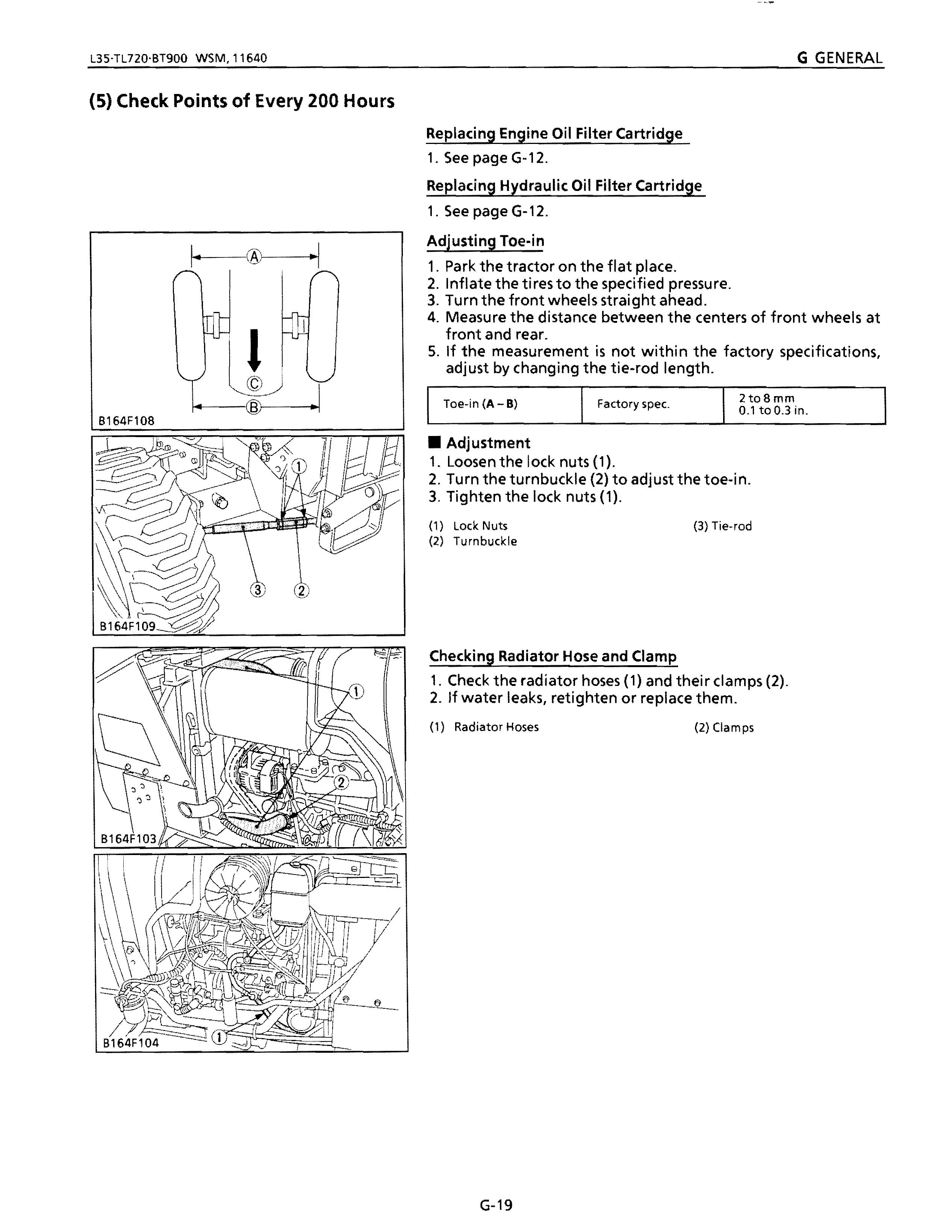
Adjusting Toe-in
1. Park the tractor on the flat place.
2. Inflate the tires to the specified pressure.
3. Turn the front wheels straight ahead.
4. Measure the distance between the centers of front wheels at front and rear.
S. If the measurement is not within the factory specifications, adjust by changing the tie-rod length.
2to8mm
Toe-in (A - B) Factory spec. 0.1 to 0.3 in.
• Adjustment
1. Loosen the lock nuts (1).
2. Turn the turnbuckle (2) to adjust the toe-in.
3. Tighten the lock nuts (1).
(1) Lock Nuts (3) Tie-rod (2) Turnbuckle
Checking Radiator Hose and Clamp
1. Check the radiator hoses (1) and their clamps (2).
2. If water leaks, retighten or replace them.
(1) Radiator Hoses (2) Clamps
(6) Check Points of Every 400 Hours
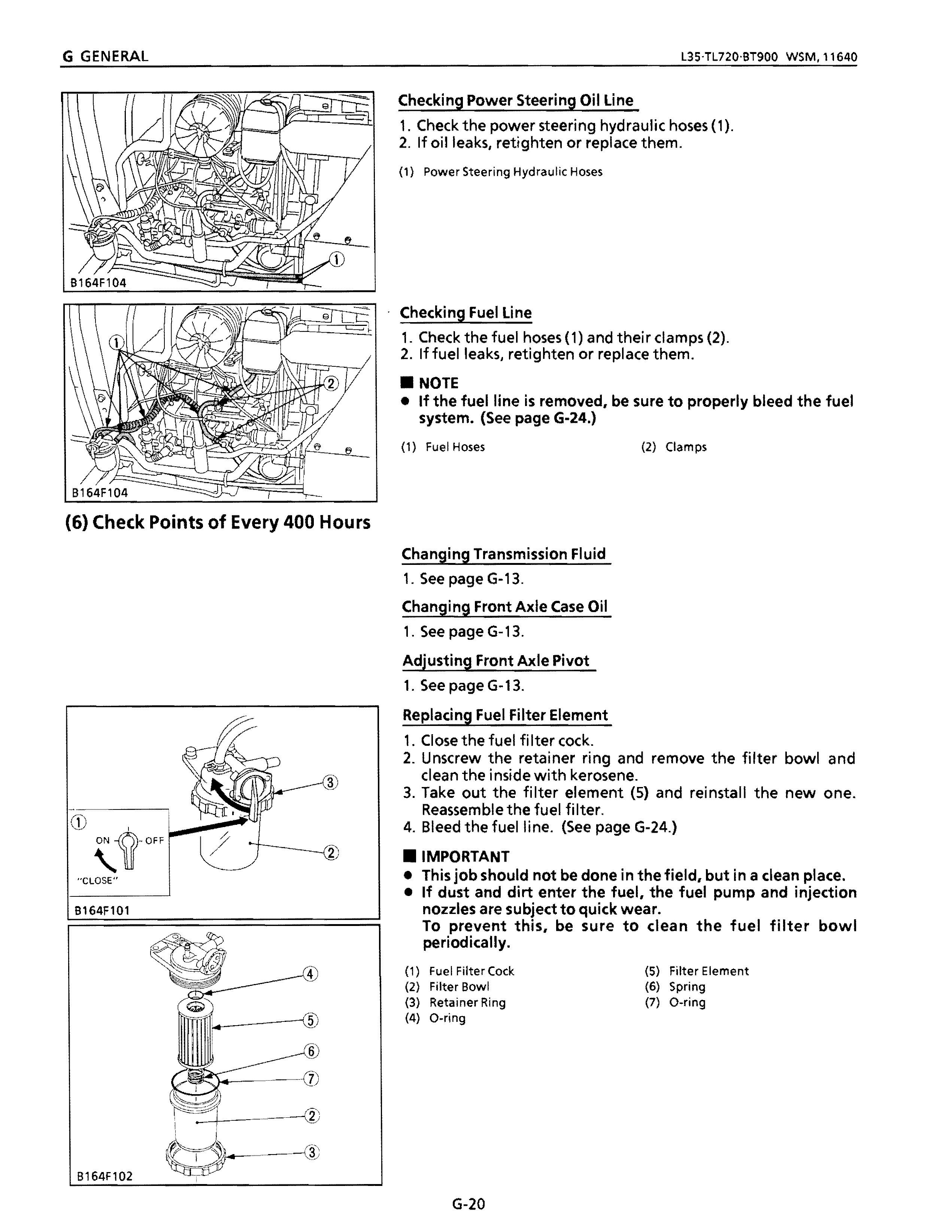
Checking Power Steering Oil line
1, Check the power steering hydraulic hoses (1), 2, If oil leaks, retighten or replace them.
(1) Power Steering Hydraulic Hoses
Checking Fuel line
1. Check the fuel hoses (1) and their clamps (2).
2. If fuel leaks, retighten or replace them
• NOTE
• If the fuel line is removed, be sure to properly bleed the fuel system. (See page G-24.)
(1) Fuel Hoses (2) Clamps
Changing Transmission Fluid
1. See page G-13.
Changing Front Axle Case Oil
1. See page G-1 3.
Adjusting Front Axle Pivot
1. See page G-13.
Replacing Fuel Filter Element
1. Close the fuel filter cock.
2. Unscrew the retainer ring and remove the filter bowl and clean the inside with kerosene.
3. Take out the filter element (5) and reinstall the new one. Reassemble the fuel filter.
4. Bleed the fuel line. (See page G-24.)
• IMPORTANT
• This job should not be done in the field. but in a dean place.
• If dust and dirt enter the fuel, the fuel pump and injection nozzles are subject to quick wear. To prevent this, be periodically. sure to clean the fuel filter bowl
(1) (2) (3) (4) Fuel Filter Cock Filter Bowl Retainer Ring D-ring (5) (6) (7) Filter Element Spring D-ring
(7) Check Points of Every 800 Hours
A109F020
0329Fon .-(A)
0329F078 [AI Gear Case Side
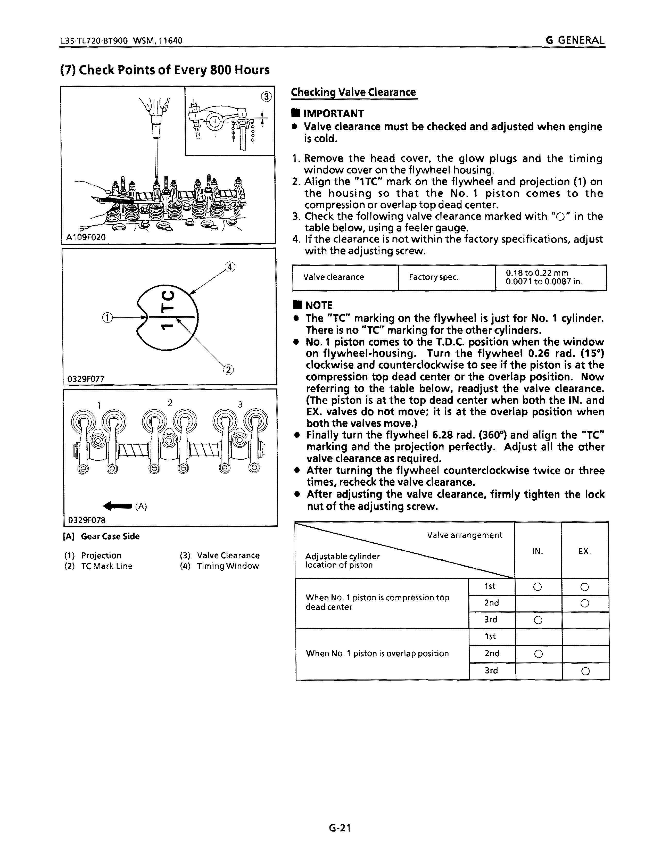
(1) Projection (3) Valve Clearance (2) TC Mark. Line (4) Timing Window
Checking Valve Clearance
• IMPORTANT
• Valve clearance must be checked and adjusted when engine is cold.
1. Remove the head cover, the glow plugs and the timing window cover on the flywheel housing.
2. Align the "1TC" mark on the flywheel and projection (1) on the housing so that the No.1 piston comes to the compression or overlap top dead center.
3. Check the following valve clearance marked with "0" in the table below, using a feeler gauge.
4. Ifthe clearance is not within the factory specifications, adjust with the adjusting screw.
0.1BtoO.22mm
Valve clearance Factory spec. 0.0071 to 0.0087 in
• NOTE
• The "TC" marking on the flywheel is just for No.1 cylinder. There is no "TC" marking for the other cylinders.
• No.1 piston comes to the T.D.C. position when the window on flywheel-housing. Turn the flywheel 0.26 rad. (15°) clockwise and counterclockwise to see if the piston is at the compression top dead center or the overlap position. Now referring to the table below. readjust the valve clearance. (The piston is at the top dead center when both the IN. and EX. valves do not move; it is at the overlap position when both the valves move.)
• Finally turn the flywheel 6.28 rad. (3600 ) and align the "TC" marking and the projection perfectly. Adjust all the other valve clearance as required.
• After turning the flywheel counterclockwise twice or three times. recheck the valve clearance.
• After adjusting the valve clearance. firmly tighten the lock nut of the adjusting screw
Adjustable cylinder location of piston
(8) Check Points of Every 1 Year
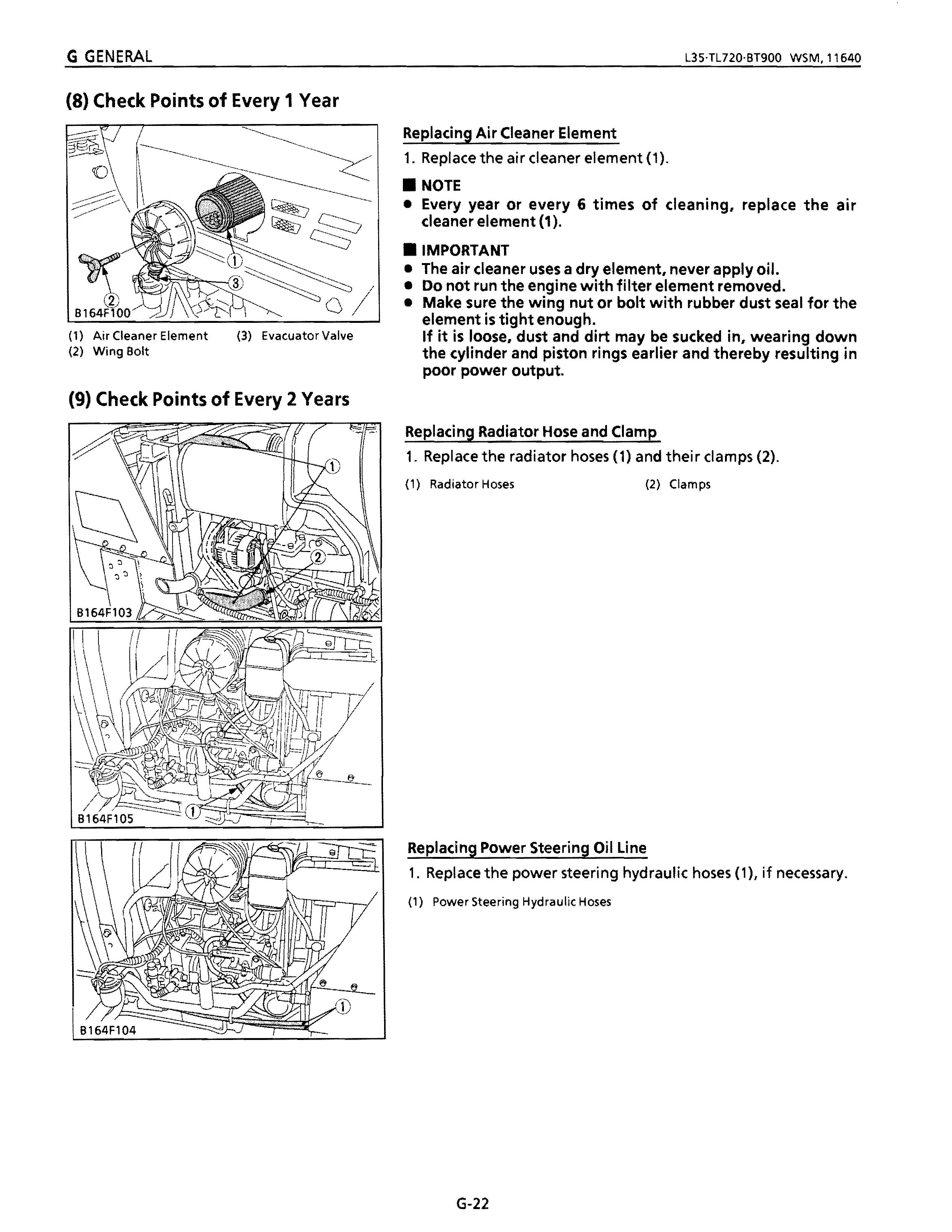
(1) Air Cleaner Element (3) Evac.uator Valve (2) Wing Bolt
(9) Check Points of Every 2 Years
Replacing Air Cleaner Element
1. Replace the air cleaner element (1).
• NOTE
• Every year or every 6 times of cleaning, replace the air cleaner element (1)
• IMPORTANT
• The air cleaner uses a dry element, never apply oil.
• Do not run the engine with filter element removed.
• Make sure the wing nut or bolt with rubber dust seal for the element is tight enough. If it is loose, dust and dirt may be sucked in, wearing down the cylinder and piston rings earlier and thereby resulting in poor power output.
Replacing Radiator Hose and Clamp
1. Replace the radiator hoses (1) and their clamps (2).
(1) Radiator Hoses (2) Clamps
Replacing Power Steering Oil Line
1. Replace the power steering hydraulic hoses (1), if necessary.
(1) Power Steering Hydraulic Hoses
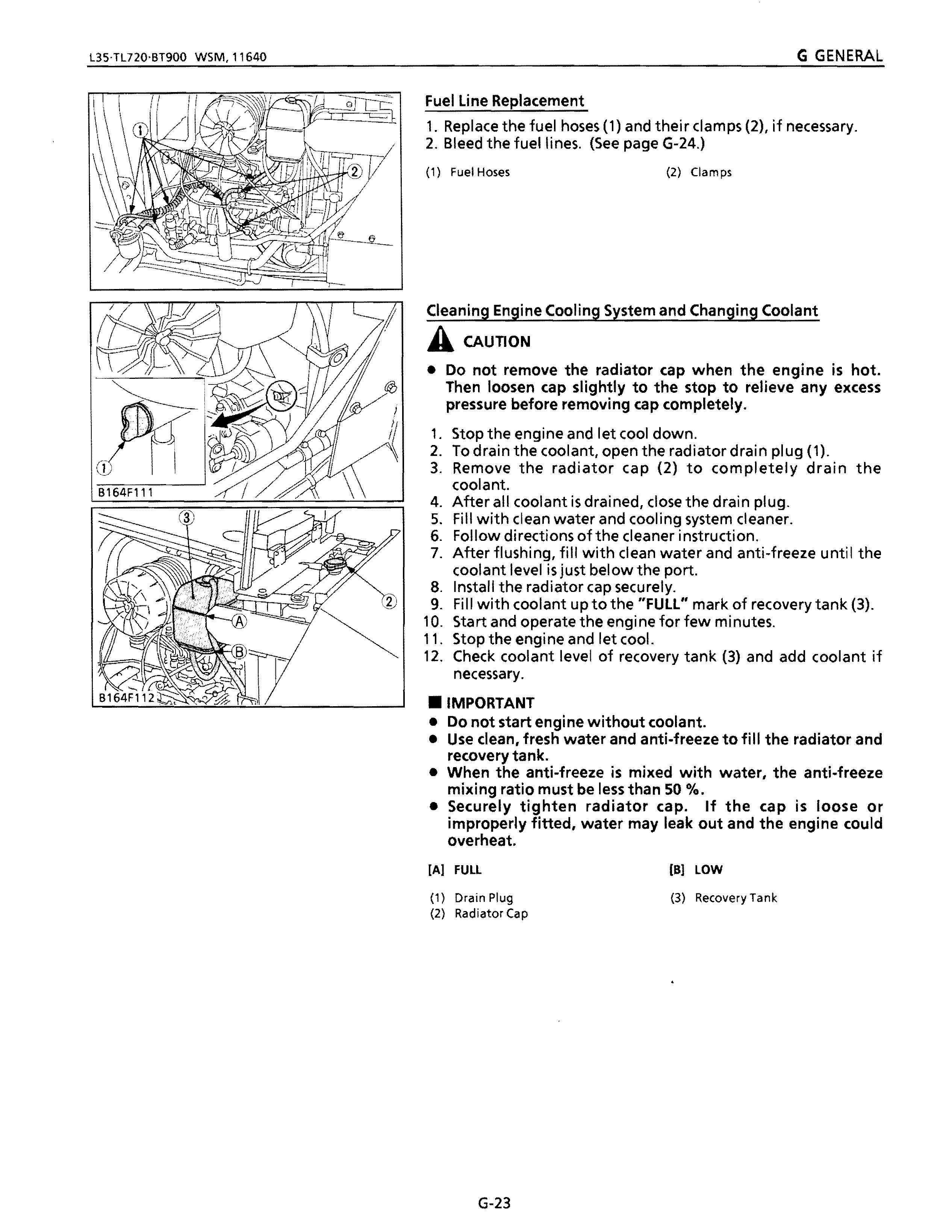
Fuel Line Replacement
1. Replace the fuel hoses (1) and their clamps (2t if necessary.
2. Bleed the fuel lines. (See page G-24.)
(1) Fuel Hoses (2) Clamps
Cleaning Engine Cooling System and Changing Coolant
ACAUTION
• Do not remove the radiator cap when the engine is hot. Then loosen cap slightly to the stop to relieve any excess pressure before removing cap completely.
1. Stop the engine and let cool down.
2. To drain the coolant, open the radiator drain plug (1).
3. Remove the radiator cap (2) to completely drain the coolant.
4. After all coolant is drained, close the drain plug.
5. Fill with clean water and cooling system cleaner.
6. Follow directions ofthe cleaner instruction.
7. After flushing, fill with clean water and anti-freeze until the coolant level is just below the port.
8. Install the radiator cap securely.
9. Fill with coolant up to the "FUll" mark of recovery tank (3).
10. Start and operate the engine for few minutes.
11. Stop the engine and let cool.
12. Check coolant level of recovery tank (3) and add coolant if necessary .
• IMPORTANT
• Do not start engine without coolant.
• Use clean, fresh water and anti-freeze to fill the radiator and recovery tank.
• When the anti-freeze is mixed with water, the anti-freeze mixing ratio must be less than 50 %.
• Securely tighten radiator cap. If the cap is loose or improperly fitted, water may leak out and the engine could overheat.
[AI FULL (8) LOW
(1) Drain Plug (3) Recovery Tank (2) Radiator Cap