Group ECU_Level_ - ECU Control Software (Final Tier 4)
Group EIC - EIC Control Software
Group FCC - FCC Control Software
Group HCC - HCC Control Software
Group ICA - ICA Control Software
Group JDL - JDL Control Software
Group OIC - OIC Control Software
Group PDU - PDU Control Software
Group PTF - PTF Control Software
Group PTQ - PTQ Control Software
Group PTR - PTR Control Software
Group RPT - RPT Control Software
Group SCO - SCO Control Software
Group SFA - SFA Control Software
Group SMB - SMB Control Software
Group TEC - TEC Control Software
Group TEI - TEI Control Software
Group TIH - TIH Control Software
Group TIQ - TIQ Control Software
Group VTV - VTV Control Software
Group XMC - XMC Control Software
Group XSC - XSC Control Software
Section 212 - OBSERVABLE SYMPTOMS AND SYSTEM DIAGNOSTICS
Group 20 - Engine
Group 30 - Fuel, Air Intake, and Cooling Systems
Group 40 - Electrical System
Group 45 - Electronic Control Units
Group 50A - Drive Train (without Transmission)
Group 50C - PowrReverser™ Transmission
Group 50D - PowrQuad™ Transmission
Group 60A - Steering
Group 60B - Brakes
Group 70 - Hydraulic System
Group 80B - Suspension Systems
Group 90 - Operator′s Cab
Section 220 - ENGINE
Group 20 - Exhaust Aftertreatment System, Theory of Operation
Group 50 - Tests and Adjustments
Section 230 - FUEL, AIR INTAKE AND COOLING SYSTEMS
Group 05 - General Information
Group 20A - Fuel System, Theory of Operation
Group 20B - Air Intake System, Theory of Operation
Group 20C - Cooling System, Theory of Operation
Group 20E - Cold-Weather Starting System, Theory of Operation
Group 50 - Fuel, Air Intake, and Cooling Systems - Tests and Adjustments
Section 239 - FUEL, AIR INTAKE, AND COOLING SYSTEMS - COMPONENT INFORMATION
Group 40A - Fuel System, Component Information
Group 40C - Cooling System, Component Information
Group 40D - Charge Air Circuit, Component Information
Group 40E - Cold Start System, Component Information
Section 240 - ELECTRICAL SYSTEM
Group 05 - Electrical System - General Information
Group 20 - Electrical System - Theory of Operation
Group 30A - 30A - Electrical System - Schematics
Group 50AA - 50AA - Starter Motor and Charging Circuit
Group 50AC - 50AC - External Cold Start Aid
Group 50BA - 50BA - Lights
Group 50BB - 50BB - Worklights
Group 50BC - 50BC - Dome Light and Access Step Light
Group 50BD - 50BD - Turn-Signal Lights
Group 50CA - 50CA - Operator′s Seat
Group 50CB - 50CB - Acoustic Alarms
Group 50CC - 50CC - Windshield and Rear Window Wipers
Group 50CD - 50CD - Heater/Ventilation/Air-Conditioning System
Group 50CE - 50CE - Sockets
Group 50CF - 50CF - Radio
Group 50CH - 50CH - Accessories
Group 50EA - 50EA - TEC Control Software and Implement CAN Bus
Group 50EB - 50EB - AutoTrac™
Group 50EC - 50EC - Radar
Group 50ED - 50ED - JDLink™ Service ADVISOR™ Remote
Group 50FA - 50FA - Electronic Engine Control
Group 50FB - 50FB - Immobilizer
Group 50FC - 50FC - Fuel System
Group 50GA - 50GA - PowrQuad™ Transmission
Group 50GD - 50GD - CommandQuad™ Transmission
Group 50GE - 50GE - PowrReverser™ Transmission
Group 50GH - 50GH - Differential Lock
Group 50GI - 50GI - Front-Wheel Drive
Group 50GJ - 50GJ - Rear PTO
Group 50GK - 50GK - Front PTO
Group 50GG - 50GL - Brakes
Group 50HA - 50HA - Rear Hitch
Group 50HB - 50HB - E-SCV Selective Control Valves
Group 50HD - 50HD - Suspended Front-Wheel Drive Axle
Group 50HH - 50HH - Front Loader
Group 50IA - 50IA - Display
Group 50ID - 50ID - LIN Bus Modules
Group 50JA - 50JA - Bus Systems
Group 50X - 50X - Ground Connections
Group 50ZZ - 50ZZ - Electronic Control Units
Section 245 - ELECTRONIC CONTROL UNITS
Group 05 - Electronic Control Units - General Information
Group 10B - Electronic Control Units - Interactive Tests and Calibrations
Group 10C - Electronic Control Units - Information on Programming
Group 20 - Electronic Control Units - Theory of Operation
Group Immobilize - Immobilizer Control Unit
Group AIC - AIC Control Software
Group BLC - BLC Control Software
Group CCU - CCU Control Software
Group DOI - DOI Control Software
Group ECU_Level_ - ECU Control Software (Final Tier 4)
Group EIC - EIC Control Software
Group FCC - FCC Control Software
Group GM1 - GM1 Control Software
Group GM2 - GM2 Control Software
Group HCC - HCC Control Software
Group ICA - ICA Control Software
Group JDL - JDL Control Software
Group OIC - OIC Control Software
Group PDU - PDU Control Software
Group PTF - PTF Control Software
Group PTQ - PTQ Control Software
Group PTR - PTR Control Software
Group RPT - RPT Control Software
Group SCO - SCO Control Software
Group SFA - SFA Control Software
Group SMB - SMB Control Software
Group TEC - TEC Control Software
Group TEI - TEI Control Software
Group TIH - TIH Control Software
Group TIQ - TIQ Control Software
Group VTV - VTV Control Software
Group XMC - XMC Control Software
Group XSC - XSC Control Software
Section 249 - ELECTRICAL CONNECTORS, WIRING HARNESSES, AND COMPONENTS
Group 05 - Electrical Connectors, Wiring Harnesses, and Components - General Information
Group 40 - Summary of Electrical Components and Harnesses
Group 40A - Electrical Components - Assemblies
Group 40B - Electrical Components - Sensors
Group 40E - Electrical Components - Various Devices and Equipment
Group 40F - Electrical Components - Fuses, Relays, and Diodes
Group 40G - Electrical Components - Power Supply and Alternator
Group 40H - Electrical Components - Control and Signal Devices
Group 40M - Electrical Components - Electrical Motors
Group 40R - Electrical Components - Resistors
Group 40S - Electrical Components - Switches
Group 40W - Wiring Harnesses
Group 40X - Connector
Group 40XGND - Ground Points
Group 40Y - Electrical Components - Solenoid Valves and Solenoids
Group 40Z - Electrical Components - Other
Section 250A - DRIVE TRAIN (WITHOUT TRANSMISSION)
Group 10 - Drive Train (without Transmission) - Operational Checks
Group 20 - Drive Train (without Transmission) - Theory of Operation
Group 50 - Drive Train (without Transmission) - Tests and Adjustments
Section 250C - POWRQUAD™ TRANSMISSION
Group 05 - PowrQuad™ Transmission - General Information
Group 10 - PowrQuad™ Transmission - Operational Checks
Group 20 - PowrQuad™ Transmission - Theory of Operation
Group 30 - PowrQuad™ Transmission - Schematics
Group 50 - PowrQuad™ Transmission - Tests and Adjustments
Section 259 - DRIVE TRAIN - COMPONENT INFORMATION
Group 40A - Drive Train (without Transmission) - Component Information
Group 40C - PowrQuad™ Transmission - Component Information
Section 260A - STEERING
Group 05 - Steering - General Information
Group 10 - Steering - Operational Checks
Group 20 - Steering - Theory of Operation
Group 30 - Steering - Schematics
Group 50 - Steering - Tests and Adjustments
Section 260B - BRAKES
Group 05 - Brakes - General Information
Group 10 - Brakes - Operational Checks
Group 20 - Brakes - Theory of Operation
Group 30 - Brakes - Schematics
Group 50 - Brakes - Tests and Adjustments
Section 269 - STEERING AND BRAKES - COMPONENT INFORMATION
Group 40A - Steering - Component Information
Group 40B - Brakes - Component Information
Section 270 - HYDRAULIC SYSTEM
Group 05 - Hydraulic System - General Information
Group 10 - Hydraulic System - Operational Checks
Group 20 - Hydraulic System - Theory of Operation
Group 20A - Oil Filter, Additional Oil Reservoir, Charge Pump and Hydraulic Pump - Theory of Operation
Group 20B - Rear Hitch - Theory of Operation
Group 20C - Front Hitch - Theory of Operation
Group 20D - Selective Control Valves (SCVs) - Theory of Operation
Group 20E - Independent Control Valves (ICVs) - Theory of Operation
Group 30 - Hydraulic System - Schematics
Group 50 - Hydraulic System Tests and Adjustments
Section 279 - HYDRAULIC SYSTEM - COMPONENT INFORMATION
Group 40 - Hydraulic System - Component Information
Section 280A - MACHINE-SPECIFIC SYSTEMS
Group 10 - Machine-Specific Systems - Operational Checks
Group 50 - Machine-Specific Systems - Tests and Adjustments
Section 280B - SUSPENSION SYSTEMS
Group 10 - Suspension Systems - Operational Checks
Group 20A - Suspended Front-Wheel Drive Axle - Theory of Operation
Group 20B - Mechanical Cab Suspension - Theory of Operation
Group 30A - Suspended Front-Wheel Drive Axle - Schematics
Group 50A - Suspended Front-Wheel Drive Axle - Tests and Adjustments
Group 50B - Mechanical Cab Suspension - Tests and Adjustments
Section 289 - SUSPENSION SYSTEMS - COMPONENT INFORMATION
Group 40A - Suspended Front-Wheel Drive Axle - Component Information
Group 40B - Mechanical Cab Suspension - Component Information
Section 290 - OPERATOR′S CAB
Group 10 - Operator′s Cab - Operational Checks
Group 20 - Operator′s Cab - Theory of Operation
Group 50 - Operator′s Cab - Tests and Adjustments
Section 299 - OPERATOR′S CAB - COMPONENT INFORMATION
Group 40 - Air Conditioning System - Component Information
Section 300 - SPECIAL TOOLS
Group 05 - General Information
DOWNLOAD DIAGNOSIS TECHNICAL MANUAL
DOWNLOAD DIAGNOSIS TECHNICAL MANUAL
Foreword
The diagnostic technical manual is written for an experienced technician. Essential tools required to perform certain type of work are identified in Section 300, and are recommended for use.
Live with safety: Read the safety messages in the introduction of this manual and the cautions presented throughout the text.
CAUTION:
This is the safety-alert symbol. When the symbol is shown on the equipment or in a manual, be alert to the potential for personal injury.
Diagnostic technical manuals are comprised of general information, checks, theory of operation, schematic and diagnostic procedures. Sections in a diagnostic technical manual help quickly identify the likely cause of routine failures. Component sections include images of the component or connector and location on the equipment.
The diagnostic technical manual references component manuals and repair technical manuals. Repair technical manuals are organized for various components requiring service instruction.
Both diagnostic and repair technical manuals are concise guides for specific equipment. They are on-the-job instructions containing vital information to diagnose, analyze, test, and repair the equipment.
DOWNLOAD
DIAGNOSIS TECHNICAL MANUAL
DOWNLOAD DIAGNOSIS TECHNICAL MANUAL
Group 05 - Safety Measures
General Information - Safety - Summary of References
General Information - Safety - Summary of References
Recognize Safety Information
Understand Signal Words
Follow Safety Instructions
Prevent Machine Runaway
Operating the Tractor Safely
Operating the Loader Tractor Safely
Passenger Seat
Use Safety Lights And Devices
Towing Trailers/Implements Safely (Mass)
Use Caution on Slopes and Uneven Terrain
Freeing a Mired Machine
Avoid Backover Accidents
Handle Fuel Safely Avoid Fires
Handling Batteries Safely
Prepare for Emergencies
Avoid High-Pressure Fluids
Service Cooling System Safely
Remove Paint Before Welding or Heating
Avoid Heating Near Pressurized Fluid Lines
Work In Ventilated Area
Avoid Contact with Agricultural Chemicals
Handle Agricultural Chemicals Safely
Stay Clear of Rotating Drivelines
Wear Protective Clothing
Protect Against Noise
Practice Safe Maintenance
Stay Away from the Hot Exhaust System
Exhaust Filter Cleaning
Clean Exhaust Filter Safely
Read Operator Manuals for ISOBUS Devices
Use Seat Belt Properly
Park Machine Safely
Use Proper Lifting Equipment
Construct Dealer-Made Tools Safely
Support Machine Properly
Work in Clean Area
Illuminate Work Area Safely
Service Machines Safely
Service Accumulator Systems Safely
Servicing Tires Safely
Use Proper Tools
Service Front-Wheel Drive Tractor Safely
Avoid Eye Contact with Radar
Keep ROPS Installed Properly
Replace Safety Signs
Replace Safety Decals
Dispose of Waste Properly
Live With Safety
Safety Measures on Electronic Control Units
Servicing Electronic Control Units
Welding Near Electronic Control Units
Keep Electronic Control Unit Connectors Clean.
Safety Instructions for Replacing a Halogen Bulb
Safety Instructions for Replacing Xenon (HID) Bulbs and Ballast Units
Recognize Safety Information
Safety-alert symbol
This is a safety-alert symbol. When you see this symbol on your machine or in this manual, be alert to the potential for personal injury.
Follow recommended precautions and safe operating practices.
Understand Signal Words
Signal Words
A signal word DANGER, WARNING, or CAUTION is used with the safety-alert symbol. DANGER identifies the most serious hazards.
DANGER or WARNING safety signs are located near specific hazards. General precautions are listed on CAUTION safety signs. CAUTION also calls attention to safety messages in this manual.
Follow Safety Instructions
Safety Messages
Carefully read all safety messages in this manual and on your machine safety signs. Keep safety signs in good condition. Replace missing or damaged safety signs. Be sure new equipment components and repair parts include the current safety signs. Replacement safety signs are available from your John Deere dealer.
There can be additional safety information contained on parts and components sourced from suppliers that is not reproduced in this operator′s manual.
Learn how to operate the machine and how to use controls properly. Do not let anyone operate without instruction.
Keep your machine in proper working condition. Unauthorized modifications to the machine may impair the function and/or safety and affect machine life.
If you do not understand any part of this manual and need assistance, contact your John Deere dealer.
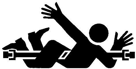
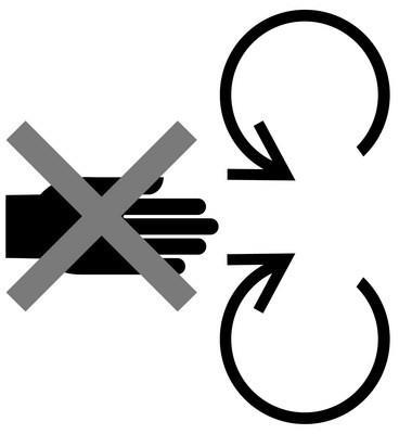
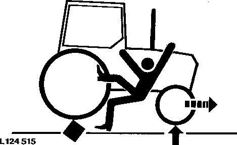
Prevent Machine Runaway
Machinery Runaway
Avoid possible injury or death from machinery runaway.
Do not start engine by shorting across starter terminals. Machine will start in gear if normal circuitry is bypassed.
NEVER start engine while standing on ground. Start engine only from operator’s seat, with transmission in neutral or park.
Operating the Tractor Safely
You can reduce the risk of accidents by following these simple precautions:
Use your tractor only for jobs it was designed to perform, for example, pushing, pulling, towing, actuating, and carrying a variety of interchangeable equipment designed to conduct agricultural work. This tractor is not intended to be used as a recreational vehicle.
Read this operator’s manual before operating the tractor and follow operating and safety instructions in the manual and on the tractor.
Follow operation and ballasting instructions found in the operator’s manual for your implements/attachments, such as front loaders
Make sure that everyone is clear of machine, attached equipment, and work area before starting engine or operation. Keep hands, feet, and clothing away from power-driven parts
Driving Concerns
Never get on or off a moving tractor.
Keep all children and nonessential personnel off tractors and all equipment.
Never ride on a tractor unless seated on a John Deere approved seat with seat belt.
Keep all shields/guards in place.
Use appropriate visual and audible signals when operating on public roads.
Move to side of road before stopping.
Reduce speed when turning, applying individual brakes, or operating around hazards on rough ground or steep slopes.
Couple brake pedals together for road travel.
Pump brakes when stopping on slippery surfaces.
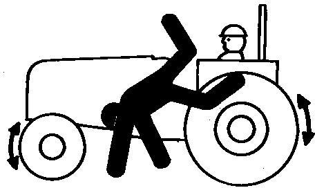
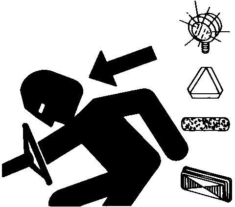
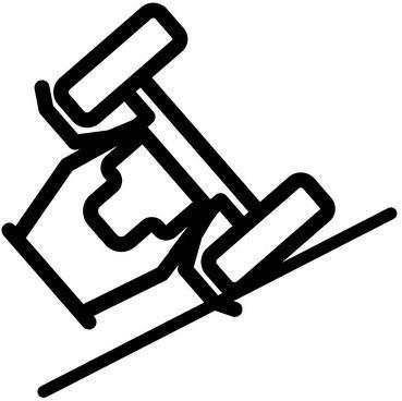
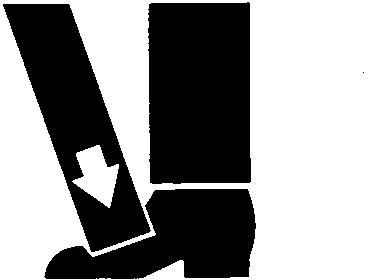
Safety Fall Off Tractor
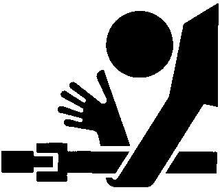
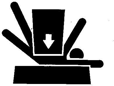
Safety PTO
Towing Loads
Be careful when towing and stopping heavy loads. Stopping distance increases with speed and weight of towed loads, and on slopes. Towed loads with or without brakes that are too heavy for the tractor or are towed too fast can cause loss of control.
Consider the total weight of the equipment and its load.
Hitch towed loads only to approved couplings to avoid rearward upset.
Parking and Leaving the Tractor
Before dismounting, shut off SCVs, disengage PTO, stop engine, lower implements/attachments to ground and securely engage park mechanism, including the park pawl and park brake. In addition, if tractor is left unattended, remove key. Leaving transmission in gear with engine off will NOT prevent the tractor from moving.
Never go near an operating PTO or an operating implement.
Wait for all movement to stop before servicing machinery.
Common Accidents
Unsafe operation or misuse of the tractor can result in accidents. Be alert to hazards of tractor operation.
The most common accidents involving tractors:
Tractor rollover
Collisions with motor vehicles
Improper starting procedures
Entanglement in PTO shafts
Falling from tractor
Crushing and pinching during hitching
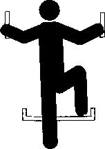
Operating the Loader Tractor Safely
Loader Tractor
When operating a machine with a loader application, reduce speed as required to ensure good tractor and loader stability.
To avoid tractor rollover and damage to front tires and tractor, do not carry load with your loader at a speed over 10 km/h (6 mph).
To avoid tractor damage do not use a front loader or a sprayer tank if the tractor is equipped with a 3 Meter Front Axle.
Never allow anyone to walk or work under a raised loader.
Do not use loader as a work platform.
Do not lift or carry anyone on loader, in bucket, or on implement or attachment.
Lower loader to ground before leaving operators station.
The Rollover Protective Structure (ROPS) or cab roof, if equipped, may not provide sufficient protection from load falling onto the operators station. To prevent loads from falling onto the operators station, always use appropriate implements for specific applications (that is, manure forks, round bale forks, round bale grippers, and clampers).
Ballast tractor in accordance to Ballast Recommendations in PREPARE TRACTOR section.
Passenger Seat
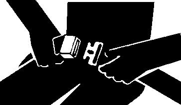
Use Seat Belt
The passenger seat is intended only for transport of a passenger in on-road operations (i.e. transport from farm to field).
If it is necessary to transport a passenger, the passenger seat is the only means of transport of a passenger condoned by John Deere.
Use Safety Lights and Devices
Prevent collisions between other road users, slow moving tractors with attachments or towed equipment, and self-propelled machines on public roads. Frequently check for traffic from the rear, especially in turns, and use turn signal lights.
Use headlights, flashing warning lights, and turn signals day and night. Follow local regulations for equipment lighting and marking. Keep lighting and marking visible, clean, and in good working order. Replace or repair lighting and marking that has been damaged or lost. An implement safety lighting kit is available from your John Deere dealer.
Towing Trailers/Implements Safely (Mass)
Towing trailers/implements safely (mass)
Stopping distance increases with speed and mass of trailer/implement, and when transporting on slopes. Towed mass with or without brakes that is too heavy for the tractor or is towed too fast can cause loss of control. Consider the total weight of the equipment and its load.
Tow Towed Mass Safely
Trailer/implement brake system
- unbraked
- independent ..........
- overrun brake
- hydraulic brake
- single-line air brake
- dual-line air brake
Top speed
25 km/h (15.5 mph)
25 km/h (15.5 mph)
25 km/h (15.5 mph)
25 km/h (15.5 mph)
25 km/h (15.5 mph)
Maximum design speed
There may be legal limits in force that restrict travel speeds to figures lower than those quoted here.
Use additional caution when towing loads under adverse surface conditions, when turning, and on inclines.
Use Caution On Slopes and Uneven Terrain
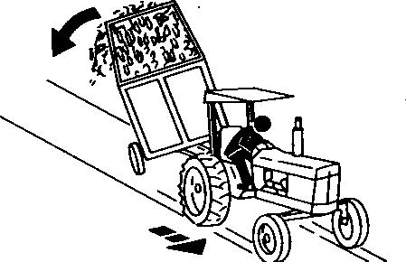
Avoid holes, ditches, and obstructions which cause the tractor to tip, especially on slopes. Avoid sharp uphill turns. Driving forward out of a ditch, mired condition, or up a steep slope could cause tractor to tip over rearward. Back out of these situations if possible.
Danger of overturn increases greatly with narrow tread setting, at high speed.
Not all conditions that can cause a tractor to overturn are listed. Be alert for any situation in which stability may be compromised.
Slopes are a major factor related to loss-of-control and tip-over accidents, which can result in severe injury or death. Operation on all slopes requires extra caution
Never drive near the edge of a gully, drop-off, ditch, steep embankment, or a body of water. The machine could suddenly roll over if a wheel goes over the edge or the ground caves in
Choose a low ground speed so you will not have to stop or shift while on a slope.
Avoid starting, stopping or turning on a slope. If the tires lose traction, disengage the PTO and proceed slowly, straight down the slope.
Keep all movement on slopes slow and gradual. Do not make sudden changes in speed or direction, which could cause the machine to roll over.
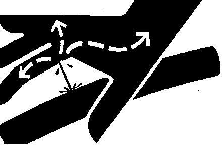
Freeing a Mired Machine
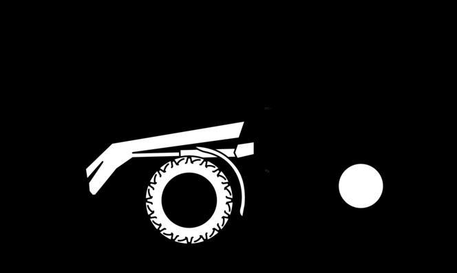
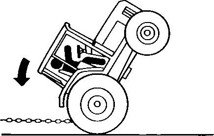
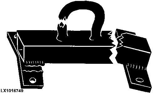
Tractor Tipping
Attempting to free a mired machine can involve safety hazards such as the mired tractor tipping rearward, the towing tractor overturning, and the tow chain or tow bar (a cable is not recommended) failing and recoiling from its stretched condition.
Back your tractor out if it gets mired down in mud. Unhitch any towed implements. Dig mud from behind the rear wheels. Place boards behind the wheels to provide a solid base and try to back out slowly. If necessary, dig mud from the front of all wheels and drive slowly ahead.
If necessary to tow with another unit, use a tow bar or a long chain (a cable is not recommended). Inspect the chain for flaws. Make sure all parts of towing devices are of adequate size and strong enough to handle the load.
Always hitch to the drawbar of the towing unit. Do not hitch to the front pushbar attachment point. Before moving, clear the area of people. Apply power smoothly to take up the slack: a sudden pull could snap any towing device causing it to whip or recoil dangerously.
Avoid Backover Accidents
Avoid Backover Accidents
Before moving machine, be sure that all persons are clear of machine path. Turn around and look directly for best visibility. Use a signal person when backing if view is obstructed or when in close quarters.
Do not rely on a camera to determine if personnel or obstacles are behind the machine. The system can be limited by many factors including maintenance practices, environmental conditions, and operating range.
Handle Fluids Safely—Avoid
Fires
Avoid Fires
When you work around fuel, do not smoke or work near heaters or other fire hazards.
Store flammable fluids away from fire hazards. Do not incinerate or puncture pressurized containers.
Make sure machine is clean of trash, grease, and debris.
Do not store oily rags; they can ignite and burn spontaneously.
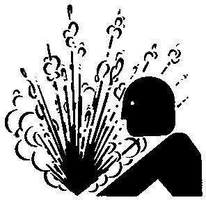
Handling Batteries Safely
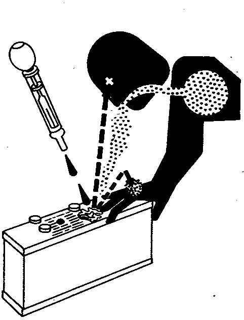
Caution
Caution
Battery gas can explode. Keep sparks and flames away from batteries. Use a flashlight to check battery electrolyte level.
Never check battery charge by placing a metal object across the posts. Use a voltmeter or hydrometer.
Always remove grounded (-) battery clamp first and replace grounded clamp last.
Sulfuric acid in battery electrolyte is poisonous and strong enough to burn skin, eat holes in clothing, and cause blindness if splashed into eyes.
Avoid hazards by:
Filling batteries in a well-ventilated area
Wearing eye protection and rubber gloves
Avoiding use of air pressure to clean batteries
Avoiding breathing fumes when electrolyte is added
Avoiding spilling or dripping electrolyte
Using correct battery booster or charger procedure.
If acid is spilled on skin or in eyes:
1. Flush skin with water.
2. Apply baking soda or lime to help neutralize the acid.
3. Flush eyes with water for 15 30 minutes. Get medical attention immediately.
If acid is swallowed:
1. Do not induce vomiting.
2. Drink large amounts of water or milk, but do not exceed 2 L (2 qt.).
3. Get medical attention immediately.
WARNING: Battery posts, terminals, and related accessories contain lead and lead compounds, chemicals known to the State of California to cause cancer and reproductive harm. Wash hands after handling.
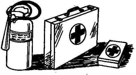
Prepare for Emergencies
First Aid Kit
Be prepared if a fire starts.
Keep a first aid kit and fire extinguisher handy.
Keep emergency numbers for doctors, ambulance service, hospital, and fire department near your telephone.
Avoid High-Pressure Fluids
Inspect hydraulic hoses periodically – at least once per year – for leakage, kinking, cuts, cracks, abrasion, blisters, corrosion, exposed wire braid or any other signs of wear or damage.
Replace worn or damaged hose assemblies immediately with John Deere approved replacement parts.
Escaping fluid under pressure can penetrate the skin causing serious injury.
Avoid the hazard by relieving pressure before disconnecting hydraulic or other lines. Tighten all connections before applying pressure.
Search for leaks with a piece of cardboard. Protect hands and body from high-pressure fluids.
If an accident occurs, see a doctor immediately. Any fluid injected into the skin must be surgically removed within a few hours or gangrene may result. Doctors unfamiliar with this type of injury should reference a knowledgeable medical source. Such information is available in English from Deere & Company Medical Department in Moline, Illinois, U.S.A., by calling 1-800-822-8262 or +1 309-748-5636.
Service Cooling System Safely
Cooling System
Explosive release of fluids from pressurized cooling system can cause serious burns.
Shut off engine. Only remove filler cap when cool enough to touch with bare hands. Slowly loosen cap to first stop to relieve pressure before removing completely.
High Pressure
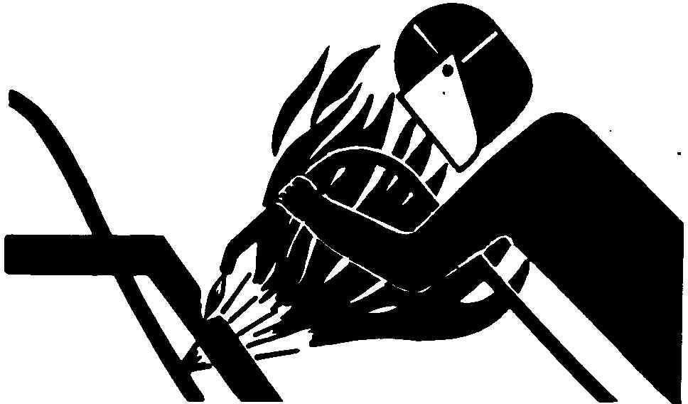
Remove Paint Before Welding or Heating
Toxic Fumes
Avoid potentially toxic fumes and dust.
Hazardous fumes can be generated when paint is heated by welding, soldering, or using a torch.
Remove paint before heating:
Remove paint a minimum of 100 mm (4 in.) from area to be affected by heating. If paint cannot be removed, wear an approved respirator before heating or welding.
If you sand or grind paint, avoid breathing the dust. Wear an approved respirator.
If you use solvent or paint stripper, remove stripper with soap and water before welding. Remove solvent or paint stripper containers and other flammable material from area. Allow fumes to disperse at least 15 minutes before welding or heating.
Do not use a chlorinated solvent in areas where welding will take place.
Do all work in an area that is well ventilated to carry toxic fumes and dust away.
Dispose of paint and solvent properly.
Avoid Heating Near Pressurized Fluid Lines
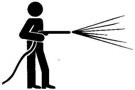
Flammable Spray
Flammable spray can be generated by heating near pressurized fluid lines, resulting in severe burns to yourself and bystanders. Do not heat by welding, soldering, or using a torch near pressurized fluid lines or other flammable materials. Pressurized lines can accidentally burst when heat goes beyond the immediate flame area.
Work In Ventilated Area
Engine exhaust fumes
Engine exhaust fumes can cause sickness or death. If it is necessary to run an engine in an enclosed area, remove the exhaust fumes from the area with an exhaust pipe extension. If you do not have an exhaust pipe extension, open the doors and get outside air into the area.
Avoid Contact with Agricultural Chemicals
Harmful Pesticides
Pesticide Use
This enclosed cab does not protect against inhaling vapor, aerosol or dust. If pesticide use instructions require respiratory protection, wear an appropriate respirator inside the cab.
Before leaving the cab, wear personal protective equipment as required by the pesticide use instructions. When re-entering the cab, remove protective equipment and store either outside the cab in a closed box or some other type of sealable container or inside the cab in a pesticide resistant container, such as a plastic bag.
Clean your shoes or boots to remove soil or other contaminated particles prior to entering the cab.
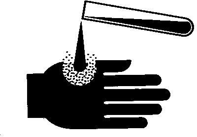
Handle Agricultural Chemicals Safely
Safety
Safety
Chemicals used in agricultural applications such as fungicides, herbicides, insecticides, pesticides, rodenticides, and fertilizers can be harmful to your health or the environment if not used carefully.
Always follow all label directions for effective, safe, and legal use of agricultural chemicals.
Reduce risk of exposure and injury:
Wear appropriate personal protective equipment as recommended by the manufacturer. In the absence of manufacturer′s instructions, follow these general guidelines:
Chemicals labeled ′Danger′ : Most toxic. Generally require use of goggles, respirator, gloves, and skin protection.
Chemicals labeled ′Warning′ : Less toxic. Generally require use of goggles, gloves, and skin protections.
Chemicals labeled ′Caution′ : Least toxic. Generally require use of gloves and skin protection.
Avoid inhaling vapor, aerosol or dust.
Always have soap, water, and towel available when working with chemicals. If chemical contacts skin, hands, or face, wash immediately with soap and water. If chemical gets into eyes, flush immediately with water.
Wash hands and face after using chemicals and before eating, drinking, smoking, or urination.
Do not smoke or eat while applying chemicals.
After handling chemicals, always bathe or shower and change clothes. Wash clothing before wearing again.
Seek medical attention immediately if illness occurs during or shortly after use of chemicals.
Keep chemicals in original containers. Do not transfer chemicals to unmarked containers or to containers used for food or drink.
Store chemicals in a secure, locked area away from human or livestock food. Keep children away.
Always dispose of containers properly. Triple rinse empty containers and puncture or crush containers and dispose of properly.
Stay Clear of Rotating Drivelines
Rotating Drivelines
Drivelines
Entanglement in rotating driveline can cause serious injury or death.
Keep tractor master shield and driveline shields in place at all times. Make sure rotating shields turn freely.
Wear close fitting clothing. Stop the engine and be sure that PTO driveline is stopped before making adjustments, connections, or cleaning out PTO driven equipment.
Do not install any adapter device between the tractor and the primary implement PTO drive shaft that will allow a 1000 rpm tractor shaft to power a 540 rpm implement at speeds higher than 540 rpm.
Do not install any adapter device that results in a portion of the rotating implement shaft, tractor shaft, or the adapter to be unguarded. The tractor master shield shall overlap the end of the splined shaft and the added adaptor device as outlined in the table.
Stay Clear of Rotating Drivelines
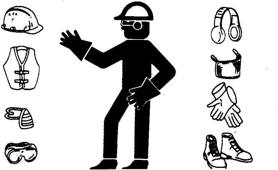
Wear Protective Clothing
Protective Clothing
Wear close fitting clothing and safety equipment appropriate to the job.
Prolonged exposure to loud noise can cause impairment or loss of hearing.
Wear a suitable hearing protective device such as earmuffs or earplugs to protect against objectionable or uncomfortable loud noises.
Operating equipment safely requires the full attention of the operator. Do not wear radio or music headphones while operating machine.
Protect Against Noise
Noise Exposure
Prolonged exposure to loud noise can cause impairment or loss of hearing.
Wear a suitable hearing protective device such as earmuffs or earplugs to protect against objectionable or uncomfortable loud noises.
Keep Area Clean
Understand service procedure before doing work. Keep area clean and dry.
Never lubricate, service, or adjust machine while it is moving. Keep hands, feet , and clothing from power-driven parts. Disengage all power and operate controls to relieve pressure. Lower equipment to the ground. Stop the engine. Remove the key. Allow machine to cool.
Securely support any machine elements that must be raised for service work.
Keep all parts in good condition and properly installed. Fix damage immediately. Replace worn or broken parts. Remove any buildup of grease, oil, or debris.
On self-propelled equipment, disconnect battery ground cable (-) before making adjustments on electrical systems or welding on machine.
On towed implements, disconnect wiring harnesses from tractor before servicing electrical system components or welding on machine.
Avoid Hot Exhaust
Safety—Hot Parts
Servicing machine or attachments with engine running can result in serious personal injury. Avoid exposure and skin contact with hot exhaust gases and components.
Exhaust parts and streams become very hot during operation. Exhaust gases and components reach temperatures hot enough to burn people, ignite, or melt common materials.
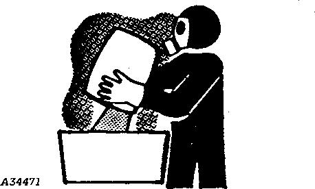
Exhaust Filter Cleaning
Safety Hot Parts
Servicing machine or attachments during exhaust filter cleaning can result in serious personal injury. Avoid exposure and skin contact with hot exhaust gases and components.
During auto or manual/stationary exhaust filter cleaning operations, the engine will run at elevated idle and hot temperatures for an extended period of time. Exhaust gases and exhaust filter components reach temperatures hot enough to burn people, or ignite, or melt common materials.
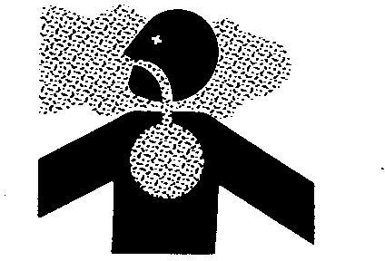
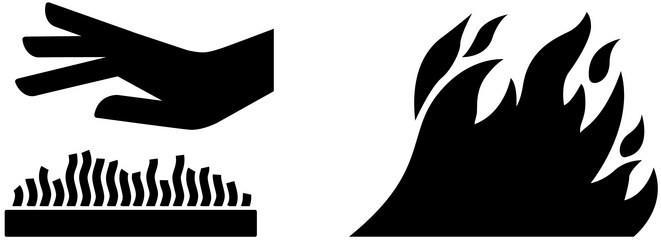
Fire Safety
Hand Over Flame
Moving Parts
During exhaust filter cleaning operations, the engine may run at elevated idle and hot temperatures for an extended period of time. Exhaust gases and exhaust filter components reach temperatures hot enough to burn people, or ignite or melt common materials.
Keep machine away from people, animals, or structures which may be susceptible to harm or damage from hot exhaust gases or components. Avoid potential fire or explosion hazards from flammable materials and vapors near the exhaust. Keep exhaust outlet away from people and anything that can melt, burn, or explode.
Closely monitor machine and surrounding area for smoldering debris during and after exhaust filter cleaning.
Adding fuel while an engine is running can create a fire or explosion hazard. Always stop engine before refueling machine and clean up any spilled fuel.
Always make sure that engine is stopped while hauling machine on a truck or trailer.
Contact with exhaust components while still hot can result in serious personal injury.
Avoid contact with these components until cooled to safe temperatures.
If service procedure requires engine to be running:
Only engage power-driven parts required by service procedure
Ensure that other people are clear of operator station and machine
Keep hands, feet, and clothing away from power-driven parts.
Always disable movement (neutral), set the parking brake or mechanism and disconnect power to attachments or tools before leaving the operator’s station.
Shut off engine and remove key (if equipped) before leaving the machine unattended.
Read Operator Manuals for ISOBUS Implements
In addition to GreenStar Applications, this display can be used as a display device for any implement that meets ISO 11783 standard. This includes capability to control ISOBUS implements. When used in this manner, information and implement control functions placed on the display are provided by the implement and are the responsibility of the implement manufacturer. Some of these implement functions could provide a hazard either to the Operator or a bystander. Read the operator manual provided by the implement manufacturer and observe all safety messages in manual and on implement prior to use.
ISOBUS refers to the ISO Standard 11783
Use Steps and Handholds Correctly
Use Handholds and Steps
Prevent falls by facing the machine when getting on and off. Maintain 3-point contact with steps, handholds, and handrails.
Use extra care when mud, snow, or moisture present slippery conditions. Keep steps clean and free of grease or oil. Never jump when exiting machine. Never mount or dismount a moving machine.
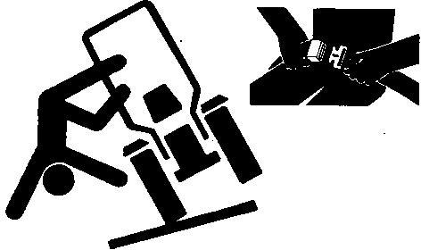
Use Seat Belt Properly
Use a Seat Belt
Use a seat belt when you operate with a roll-over protective structure (ROPS) or cab to minimize chance of injury from an accident such as an overturn.
Do not use a seat belt if operating without a ROPS or cab.
Replace entire seat belt if mounting hardware, buckle, belt, or retractor show signs of damage.
Inspect seat belt and mounting hardware at least once a year. Look for signs of loose hardware or belt damage, such as cuts, fraying, extreme or unusual wear, discoloration, or abrasion. Replace only with replacement parts approved for your machine. See your John Deere dealer.
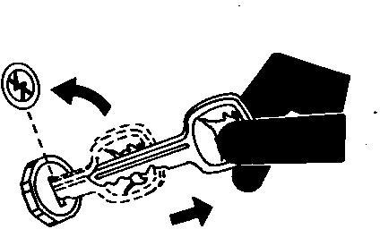
Park Machine Safely
Remove the Key
Before working on the machine:
Lower all equipment to the ground. Stop the engine and remove the key. Disconnect the battery ground strap.
Hang a "DO NOT OPERATE" tag in operator station.
Use Proper Lifting Equipment
Proper Lifting Equipment
Lifting heavy components incorrectly can cause severe injury or machine damage.
Follow recommended procedure for removal and installation of components in the manual.
Construct Dealer-Made Tools Safely
Construct Dealer-Made Tools Safely
Faulty or broken tools can result in serious injury. When constructing tools, use proper, quality materials, and good workmanship.
Do not weld tools unless you have the proper equipment and experience to perform the job.
Support Machine Properly
Support Properly
Always lower the attachment or implement to the ground before you work on the machine. If the work requires that the machine or attachment be lifted, provide secure support for them. If left in a raised position, hydraulically supported devices can settle or leak down.
Do not support the machine on cinder blocks, hollow tiles, or props that may crumble under continuous load. Do not work under a machine that is supported solely by a jack. Follow recommended procedures in this manual.
When implements or attachments are used with a machine, always follow safety precautions listed in the implement or attachment operator′s manual.
Work in Clean Area
Clean Work Area
Before starting a job:
Clean work area and machine.
Make sure you have all necessary tools to do your job. Have the right parts on hand.
Read all instructions thoroughly; do not attempt shortcuts.
Illuminate Work Area Safely
Work Area Safely
Illuminate your work area adequately but safely. Use a portable safety light for working inside or under the machine. Make sure the bulb is enclosed by a wire cage. The hot filament of an accidentally broken bulb can ignite spilled fuel or oil.
Service Machines Safely
Moving Parts
Tie long hair behind your head. Do not wear a necktie, scarf, loose clothing, or necklace when you work near machine tools or moving parts. If these items were to get caught, severe injury could result.
Remove rings and other jewelry to prevent electrical shorts and entanglement in moving parts.
Service Accumulator Systems Safely
Hydraulic Accumulator
Escaping fluid or gas from systems with pressurized accumulators that are used in air conditioning, hydraulic, and air brake systems can cause serious injury. Extreme heat can cause the accumulator to burst, and pressurized lines can be accidentally cut. Do not weld or use a torch near a pressurized accumulator or pressurized line.
Relieve pressure from the pressurized system before removing accumulator.
Relieve pressure from the hydraulic system before removing accumulator. Never attempt to relieve hydraulic system or accumulator pressure by loosening a fitting.
Accumulators cannot be repaired.
Service Tires Safely
Explosive Tire and Rim Parts
Explosive separation of a tire and rim parts can cause serious injury or death.
Do not attempt to mount a tire unless you have the proper equipment and experience to perform the job.
Always maintain the correct tire pressure. Do not inflate the tires above the recommended pressure. Never weld or heat a wheel and tire assembly. The heat can cause an increase in air pressure resulting in a tire explosion. Welding can structurally weaken or deform the wheel.
When inflating tires, use a clip-on chuck and extension hose long enough to allow you to stand to one side and NOT in front of or over the tire assembly. Use a safety cage if available.
Check wheels for low pressure, cuts, bubbles, damaged rims, or missing lug bolts and nuts.
Use Proper Tools
Proper Tools
Use tools appropriate to the work. Makeshift tools and procedures can create safety hazards.
Use power tools only to loosen threaded parts and fasteners.
For loosening and tightening hardware, use the correct size tools. DO NOT use U.S. measurement tools on metric fasteners. Avoid bodily injury caused by slipping wrenches.
Service Front-Wheel Drive Tractor Safely
Support Front and Rear Wheels
When servicing front-wheel drive tractor with the rear wheels supported off the ground and rotating wheels by engine power, always support front wheels in a similar manner. Loss of electrical power or transmission/ hydraulic system pressure will engage the front driving wheels, pulling the rear wheels off the support if front wheels are not raised. Under these conditions, front drive wheels can engage even with switch in disengaged position.
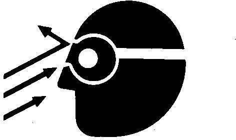
Avoid Eye Contact With Radar
Avoid Eye Contact With Radar
Radar ground speed sensor emits a very low intensity microwave signal. It will not cause any ill effects during normal use. Although intensity is low, DO NOT look directly into face of sensor while in operation, to avoid any possible eye damage.
Roll-Over Protective Structure
Make certain all parts are reinstalled correctly if the roll-over protective structure (ROPS) is loosened or removed for any reason. Tighten mounting bolts to proper torque.
The protection offered by ROPS will be impaired if ROPS is subjected to structural damage, is involved in an overturn incident, or is in any way altered by welding, bending, drilling, or cutting. A damaged ROPS should be replaced, not reused.
The seat is part of the ROPS safety zone. Replace only with John Deere seat approved for your tractor.
Any alteration of the ROPS must be approved by the manufacturer.
Replace Safety Signs
Safety Signs
Replace missing or damaged safety signs. See the machine operator’s manual for correct safety sign placement.
Replace Safety Signs
Safety Signs
Replace missing or damaged safety signs. Use this operator’s manual for correct safety sign placement.
There can be additional safety information contained on parts and components sourced from suppliers that is not reproduced in this operator′s manual.
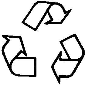
Dispose of Waste Properly
Recycle Waste
Improperly disposing of waste can threaten the environment and ecology. Potentially harmful waste used with John Deere equipment include such items as oil, fuel, coolant, brake fluid, filters, and batteries.
Use leakproof containers when draining fluids. Do not use food or beverage containers that may mislead someone into drinking from them.
Do not pour waste onto the ground, down a drain, or into any water source.
Air conditioning refrigerants escaping into the air can damage the Earth’s atmosphere. Government regulations may require a certified air conditioning service center to recover and recycle used air conditioning refrigerants.
Inquire on the proper way to recycle or dispose of waste from your local environmental or recycling center, or from your John Deere dealer.
Live With Safety
Safety Systems
Before returning machine to customer, make sure machine is functioning properly, especially the safety systems. Install all guards and shields.
Safety Measures on Electronic Control Units
CAUTION:
Before installing test equipment on tractor, always shut off the engine and turn off key switch.
CAUTION:
Always engage the park lock when performing tests with the engine running.
CAUTION:
When testing is performed with the engine running, there is a risk of injury from rotating parts.
IMPORTANT:
Do not use a test lamp on any control unit. Only use a multimeter (JT05791A/JDG1478).
IMPORTANT:
To protect electronic circuits, disconnect the battery and alternator before performing any welding on the tractor.
Servicing Electronic Control Units
Electronic Control Unit
[1]IMPORTANT:
Do not open control unit and do not clean with a high pressure spray. Moisture, dirt and other contaminants may cause permanent damage.
Control units are not repairable; replace only if indicated in the diagnostic procedure.
[2] - Since control units are the components LEAST likely to fail, isolate failure before replacing by completing the diagnostic procedure.
[3] - The wiring harness terminals and connectors for electronic control units are repairable.
[4]IMPORTANT:
Misleading diagnostic messages and poor performance may occur if an electronic control unit is not programmed identical to the original controller.
Before putting back into service, verify the control unit is programmed identical to the original controller.
Welding Near Electronic Control Units
Do not jump-start engines with arc welding equipment. Currents and voltages are too high and may cause permanent damage. Disconnect the negative (-) battery cable(s).
IMPORTANT:
Keep terminals clean and free of foreign debris. Moisture, dirt and other contaminants may cause the terminals to erode over time and not make a good electrical connection.
If a connector is not in use, put on the proper dust cap or an appropriate seal to protect it from foreign debris and moisture.
[2] -
IMPORTANT:
Do not probe through the wire insulation or through the back of the connector. Do not insert items such as paper clips or wires into connector terminals.
Make measurements on a connector terminal using JDG10466 Flex Probe Kit in SERVICEGARD.
Flex Probe Kit
JDG10466
Measure connector terminal.
[3] - Observe the locking mechanism of the connector when disconnecting and reconnecting.
[4] - Do not pull on wires to disconnect.
[5] - Before reconnecting:
Look for bent terminals; do not force connectors into each other. Replace any terminal where corrosion exists. Clean the connector of any foreign debris. Dry the connector of any moisture.
[6] - When reconnecting, make sure seals around the connector pairs are functional.
Safety Instructions for Replacing a Halogen Bulb
When replacing a halogen bulb, always comply with the following safety instructions:
CAUTION:
Always switch the lights off before you change a bulb.
CAUTION:
First allow the bulb to cool down (may cause burns).
CAUTION:
Wear safety goggles and gloves when changing the bulb.
CAUTION:
The bulb is made of glass and contains halogen gas; the bulb is under high pressure, so there is a risk of it shattering.
CAUTION:
Do NOT use any bulbs that have fallen on the ground or have scratches on their surface, as there is a risk of them shattering.
CAUTION:
Make sure that the bulb is seated correctly in its holder in the light.
CAUTION:
Check the light for signs of damage and make sure the seals are seated correctly.
IMPORTANT:
Use only bulbs that are of the same type, same voltage and same wattage as the bulb that is being replaced.
IMPORTANT:
Never touch the glass surface of the halogen bulb, hold it only by its base.
IMPORTANT:
Use a clean cloth and alcohol to remove any fingerprints from the glass bulb.
IMPORTANT:
Old halogen bulbs that have been replaced must be disposed of properly (i.e. as hazardous waste).
Safety Instructions for Replacing Xenon (HID) Bulbs and Ballast Units
When replacing a xenon (HID) bulb or ballast unit, it is essential to comply with the following safety instructions:
CAUTION:
Switch the light off and disconnect it from the power supply before changing a bulb.
CAUTION:
Never insert foreign objects or fingers into the bulb holder (high-tension voltage - potential for FATAL ACCIDENTS).
CAUTION:
The ballast unit must never be operated when the bulb is missing, as this may cause a dangerous flashover at the bulb sockets, resulting in serious damage (high-tension voltage - potential for FATAL ACCIDENTS).
CAUTION:
First allow the bulb to cool down (may cause burns).
CAUTION:
Wear safety goggles and gloves when changing the bulb.
CAUTION:
The bulb is made of glass and contains xenon gas and metallic salts; the bulb is under high pressure, so there is a risk of it shattering.
CAUTION:
Do NOT use any bulbs that have fallen on the ground or have scratches on their surface, as there is a risk of them shattering.
CAUTION:
Make sure that the bulb is seated correctly in its holder in the light.
CAUTION:
If a xenon (HID) bulb ever bursts inside a closed space (e.g. workshop), leave the area, making sure it is well ventilated, and wait for 20 minutes before returning. This will eliminate the risk to health caused by gases.
CAUTION:
Check the light for signs of damage and make sure the seals are seated correctly.
IMPORTANT:
Use only bulbs that are of the same type, same voltage and same wattage as the bulb that is being replaced.
IMPORTANT:
Never touch the glass surface of the xenon bulb, hold it only by its base.
IMPORTANT:
Use a clean cloth and alcohol to remove any fingerprints from the glass bulb.
IMPORTANT:
Old xenon (HID) bulbs that have been replaced must be disposed of properly (i.e. as hazardous waste).
Group 10 - General References
General Information - General References, Summary of References
The following list contains additional references which may be helpful when diagnosing the machine.
General Information - General References, Summary of References
Designations of Hydraulic Components
Designations of Electrical Components
General Information - Trademarks
General Information - Inch Bolt and Cap Screws, Torque Values
General Information - Metric Bolt and Cap Screws, Torque Values
General Information - Hydraulic System Inch Fittings, Torque Values
General Information - Hydraulic System Metric Fittings, Torque Values
General Information - Electrical System, Component Identification Table
General Information - Electrical System, How to Read a Diagnostic Schematic
General Information - Electrical System, Lead Numbers and Color Codes
General Information - Electrical System, Symbols in Schematic, Wiring and Harness Diagrams
General Information - Electrical System, Check the Connectors
General Information - Electrical System, Troubleshooting Unsolved Problems
General Information - Electrical System, Approach to Tabular Diagnostic Procedures
General Information - Electrical System, Visual Inspection
General Information - Electrical System, Electrical Circuit Malfunctions
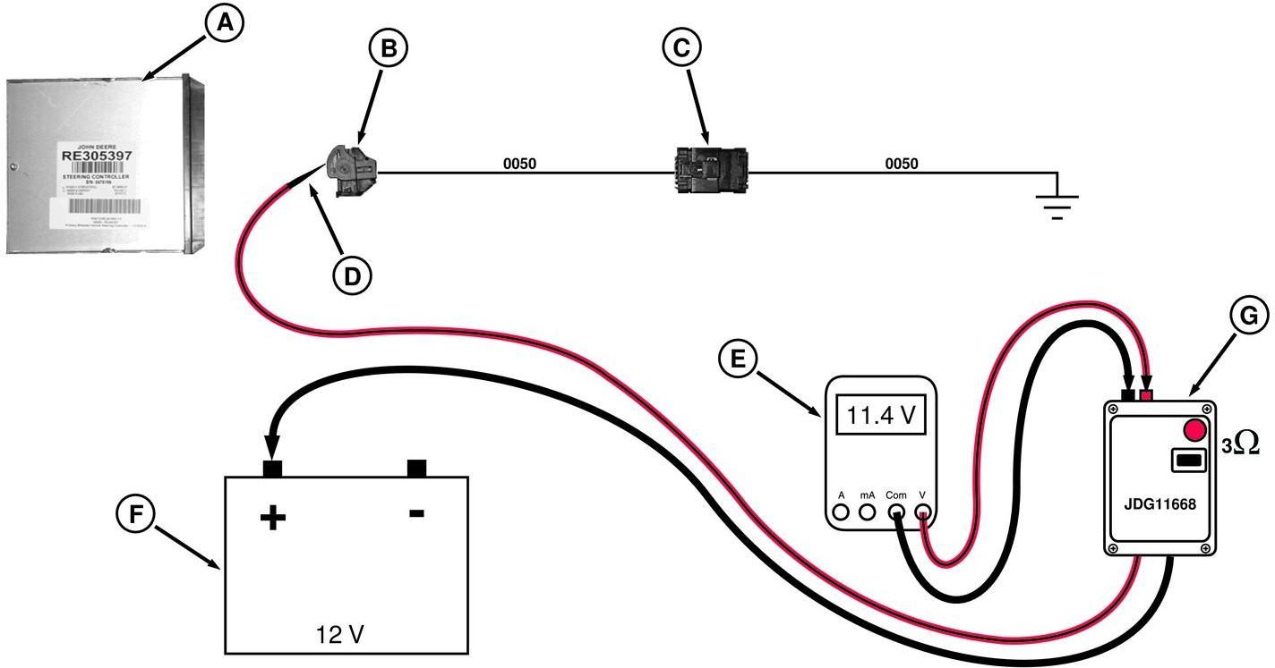
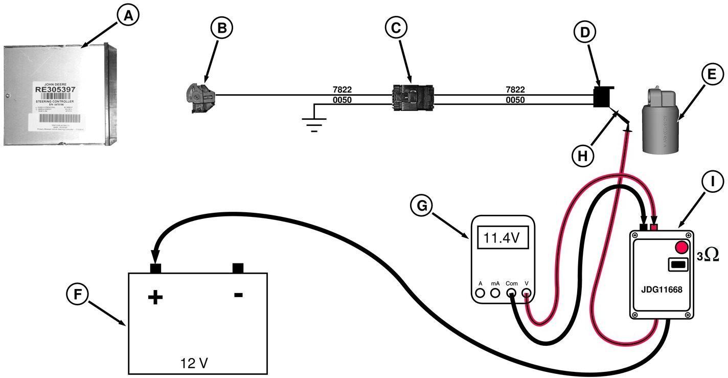
General - Electrical System, Test for Open Circuit under Load
General Information - Electrical System, Seven-Step Test Procedure
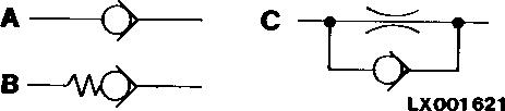
General Information - Hydraulic System, Symbols in Schematics
General - Regions and Country Versions
Trademarks
Trademarks
Trademarks
AutoPowr™ Trademark of Deere and Company
AutoPowr™/IVT™ Trademark of Deere and Company
AutoQuad II™
Trademark of Deere and Company
AutoQuad PLUS™ Trademark of Deere and Company
AutoTrac™ Trademark of Deere and Company
Bio Hy-Guard™ Trademark of Deere and Company
ClimaTrak™ Trademark of Deere and Company
ComfortGard™ Trademark of Deere and Company
ComfortGard Deluxe™ Trademark of Deere and Company
CommandARM™ Trademark of Deere and Company
CommandCenter™ Trademark of Deere and Company
COOL-GARD™ Trademark of Deere and Company
COOL-GARD II™
Trademark of Deere and Company
CoolScan™ Trademark of Deere and Company
CoolScan PLUS™
Trademark of Deere and Company
Deere™ Trademark of Deere and Company FieldCruise™ Trademark of Deere and Company
Field Doc™ Trademark of Deere and Company
Field Office™ Trademark of Deere and Company
GreenStar™ Trademark of Deere and Company
ILS™ Trademark of Deere and Company
Hy-Gard™ Trademark of Deere and Company
iTEC™ Trademark of Deere and Company
iTEC™ Basic Trademark of Deere and Company
iTEC Pro™ Trademark of Deere and Company
™
™
of Deere and Company
of Deere and Company
JDLink™ Trademark of Deere and Company
JDOffice™ Trademark of Deere and Company
John Deere™ Trademark of Deere and Company Oilscan™ Trademark of Deere and Company Parallel Tracking™ Trademark of Deere and Company
™ Trademark of Deere and Company PowerTech™ Trademark of Deere and Company
PowerTech
™
of Deere and Company PowerZero™
of Deere and Company PowrQuad™
of Deere and Company PowrQuad
™
of Deere and Company
PowrReverser™ Trademark of Deere and Company
Service ADVISOR™ Trademark of Deere and Company SERVICEGARD™ Trademark of Deere and Company
StarFire™ Trademark of Deere and Company
StarFire iTC™ Trademark of Deere and Company
StellarSupport™ Trademark of Deere and Company
SyncroPlus™ Trademark of Deere and Company
TLS™
TLS™ Plus
TouchSet™
Tractor-Implement Automation™
Triple Link Suspension™
Hydraulic Designators
Trademark of Deere and Company
Trademark of Deere and Company
Trademark of Deere and Company
Trademark of Deere and Company
Trademark of Deere and Company
The hydraulic designators are used to identify components on hydraulic schematics in this manual. In the legend, the designators are shown in alphanumeric order with a brief description. In the component identification group, designators are used in conjunction with a description and photograph or image.
The hydraulic designators begin with a letter that describes the device:
DEFINITIONS:
A Accumulator
B Sensor or Gauge
C Cylinder, Actuator, or Piston
D Check Valve
F Filter
G Valve Block, Assembly, or Gearcase
H Cooler
J Miscellaneous Component
M Motor
O Orifice
P Pump
R Reservoir or Tank
S Switch
V Valve
W Mechanical Assembly
X Diagnostic Receptacle or Coupler
Y Solenoid Valve
Z Port with Plug
Electrical Designators
Each component has an identification letter assigned to it. A number is added to the letter to separate and indicate the total components within the letter group.
DEFINITIONS:
A System, Subassembly, Control Unit, or Parts Group
B Transducer for Conversion of Non-Electrical Variables to Electrical Variables and converse
C Condenser or Capacitor
D Binary Device or Memory
E Lights, Heating, or Various Devices and Equipment
F Fuse, Circuit Breaker, or Protection Device
G Power Supply or Generator
H Monitor, Alarm, or Signaling Device
K Relay Contactor
L Inductor
M Motor
N Regulator or Amplifier
P Measuring Instrument
R Resistor or Potentiometer
S Switch
T Transformer
U Modulator or Converter
V Suppressor, Diode, Semiconductor, or Electron Tube
W Transmission Path, Harness, Conductor, or Antenna
X Terminal, Plug, or Plug and Socket Connection
Y Solenoid or other Electrically Actuated Mechanical Device
Z Electrical Filter
General Information - Inch Bolt and Cap Screws, Torque Values
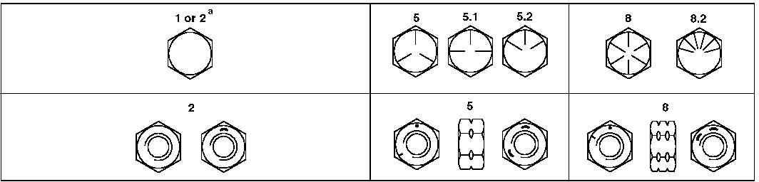
Top, SAE Grade and Head Markings; Bottom, SAE Grade and Nut Markings
Unified Inch Bolt and Cap Screw Torque Values, 1 of 2
a Grade 2 applies for hex cap screws up to 6 in. (152 mm) long. Grade 1 applies for hex cap screws over 6 in. (152 mm) long, and for all other types of bolts and screws of any length.
b "Lubricated" means coated with a lubricant such as engine oil, or fasteners with phosphate and oil coatings.
c "Dry" means plain or zinc-plated without any lubrication.
Unified Inch Bolt and Cap Screw Torque Values, 2 of 2
DO NOT use these values if a different torque value or tightening procedure is given for a specific application. Torque values listed are for general use only. Torque values listed are for general use only.
Shear bolts are designed to fail under predetermined loads. Always replace shear bolts with identical grade.
Fasteners should be replaced with the same or higher grade. If higher grade fasteners are used, these should only be tightened to the strength of the original.
Make sure fastener threads are clean and you properly start thread engagement. This will prevent them from failing when tightening.
Tighten plastic insert or crimped steel-type lock nuts to approximately 50 percent of the dry torque shown in the chart, applied to the nut, not to the bolt head. Tighten toothed or serrated-type lock nuts to the full torque value.
General Information - Metric Bolt and Cap Screws, Torque Values
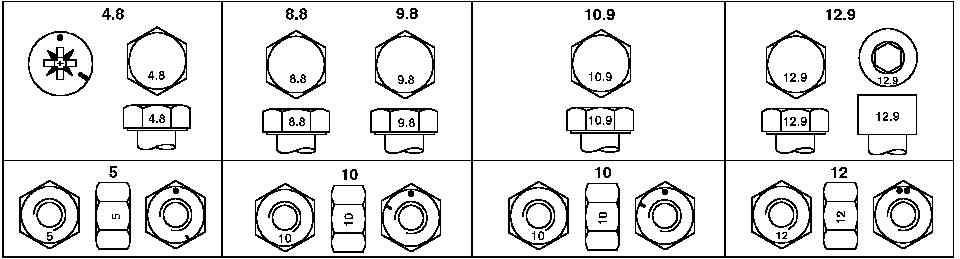
Top, Property Class and Head Markings; Bottom, Property Class and Nut Markings
Metric Bolt and Cap Screw Torque Values, 1 of 2
a "Lubricated" means coated with a lubricant such as engine oil, or fasteners with phosphate and oil coatings.
b "Dry" means plain or zinc-plated without any lubrication.
Metric Bolt and Cap Screw Torque Values, 2 of 2
DO NOT use these values if a different torque value or tightening procedure is given for a specific application. Torque values listed are for general use only. Torque values listed are for general use only.
Shear bolts are designed to fail under predetermined loads. Always replace shear bolts with identical grade.
Fasteners should be replaced with the same or higher grade. If higher grade fasteners are used, these should only be tightened to the strength of the original.
Make sure fastener threads are clean and you properly start thread engagement. This will prevent them from failing when tightening.
Tighten plastic insert or crimped steel-type lock nuts to approximately 50 percent of the dry torque shown in the chart, applied to the nut, not to the bolt head. Tighten toothed or serrated-type lock nuts to the full torque value.
General Information - Hydraulic System Inch Fittings, Torque Values
Torque values; hydraulic system
Torque values; hydraulic system
The torques in the table above are intended only as approximate values and do NOT apply if a different torque value is listed for specific fittings at other points in this manual. Check fittings regularly to make sure they are seated properly.
When replacing fittings, be sure to use parts with an equal or higher grade to the parts you are replacing. Items of hardware (e.g. union nuts) that are of a higher grade should be tightened to the same torque value as the parts they replace.
It is vitally important to make sure that the sealing faces are clean and that the O-rings have been inserted properly.
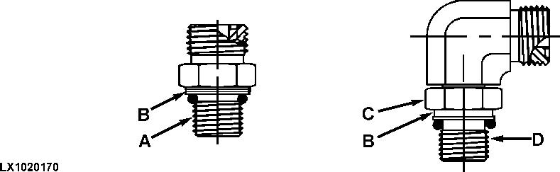
General Information - Hydraulic System Metric Fittings, Torque Values
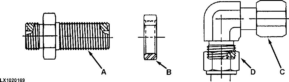
Torque values; hydraulic system
LEGEND:
A Stud-end fitting
B Groove for metric thread
C Lock nut
D Adjustable stud-end fitting
Torque values; hydraulic system
The torques in the table above are intended only as approximate values and do NOT apply if a different torque value is listed for specific fittings at other points in this manual. Check fittings regularly to make sure they are seated properly.
When replacing fittings, be sure to use parts with an equal or higher grade to the parts you are replacing. Items of hardware (e.g. union nuts) that are of a higher grade should be tightened to the same torque value as the parts they replace.
It is vitally important to make sure that the sealing faces are clean and that the O-rings have been inserted properly.
General Information - Electrical System, Component Identification Table
Each component (electrical device) and each main connector will have an identification letter assigned to it. A number is added to the letter to separate and indicate the total components within that letter group.
Component identification table
Identification Letter
Type of Device
A Assemblies
B
Conversion of non-electrical to electrical variables or vice versa
C Condenser
D Memory, timer
E Various devices and equipment
F Protection devices
G Power supply, generator
H Monitoring devices, reporting devices, signalling devices
K Relays
L Inductor
M Motor
N Regulator, amplifier
P Measuring device
R Resistor
S Switch
T Transformer
U Transducer, converter
V Semiconductor, electron ray tubes
W Transmission paths
X Connections
Y Electrically actuated mechanical device
Z Electrical filter
Examples
Electronic control units, power modules, radios, loudspeakers
Speed sensors, pressure sensors, temperature sensors, Hall sensors, inductive sensors, limit-value sensors, impulse sensors, measured-value sensors, load sensors, air flow meters, pressure switches, temperature switches
Condensers in general
Digital devices, integrated circuits, pulse counters, magnetic tape recorders
Lamps, headlights, heating devices, air-conditioning systems
Fuses, release mechanisms (bimetallic), polarity protection devices, current protection circuits
Batteries, generators, alternators, charging units
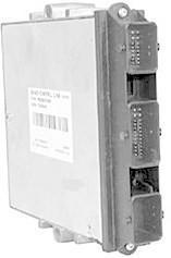
Lead 0312 (terminal 54), not supplied with power during engine starting
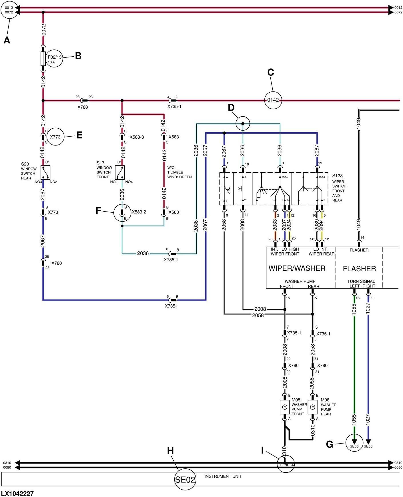
B Part designation
C Lead number
D Splice point (SP)
E Plug designation (X)
F Symbol (connector)
G Section to which lead is routed
H Section designation
I Lead 0310 (terminal 31), ground
The diagnostic schematic is divided into functional sections. It contains information about plugs (X) and connectors. Each lead is identified by a number that also indicates the cable color and the relevant circuit. The letter at the end of a lead number indicates that there are several leads with the same number but different letters. Switches and relays are shown in “OFF” position.
General Information - Electrical System, Lead Numbers and Color Codes
The last digit of the wire number indicates the color.
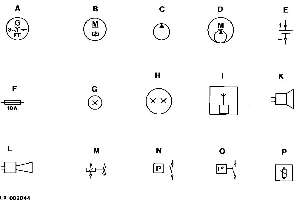
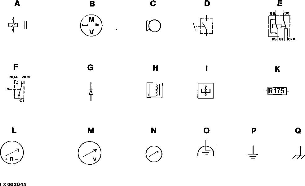
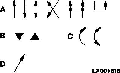
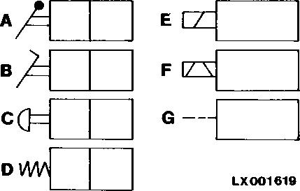
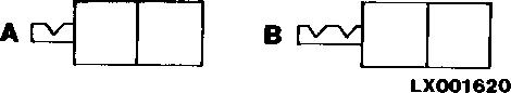
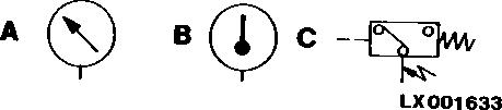
General Information - Electrical System, Symbols in Schematic, Wiring and Harness Diagrams
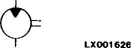
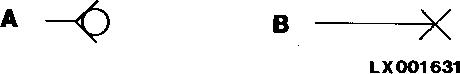
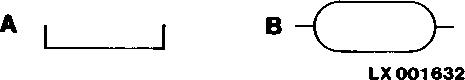
Symbols in functional schematic, wiring and harness diagrams LEGEND:
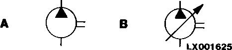
Alternator with rectifier and regulator
Starting motor with solenoid
Fuel transfer pump
Compressor
Battery
Fuse
Bulb with one luminous element
Bulb with two luminous elements
Radio
Loudspeaker
Horn
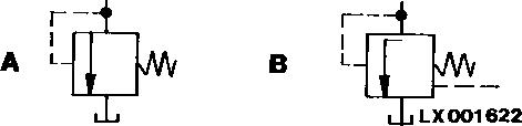
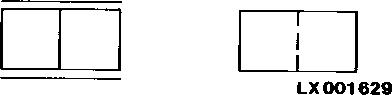
Valve, operated electro-mechanically
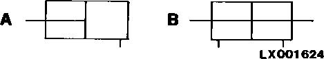
Switch, actuated by pressure
Switch, actuated by temperature
Potentiometer (variable resistor)
Symbols in functional schematic, wiring and harness diagrams
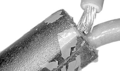
General Information - Electrical System, Check the Connectors
→NOTE:
This reference is a guideline for troubleshooting problems that still exist after standard diagnostics have been performed. These problems are typically due to specific operating conditions or intermittent failures. Depending on the situation, some or all of the following may be important.
General Information
Terminals are typically made from a base metal that is plated with tin, gold, or an alloy. The plating material helps protect the base metal of the terminal from corroding. There are two main varieties of terminals; pins (male) and sockets (female). Pins are inserted into sockets and in this way create an electrical connection between cables or electrical devices. Sockets typically contain one or more contact springs which provide firm contact points with the pin. Scraping the layer of corrosion from the terminal also removes any remaining plating material, resulting in a rapid reappearance of the corrosion.
Connector Problems
Possible causes and effects
Possible causes and effects
Cause
Corrosion, foreign material between pin and socket
Fluid, corrosion between several pins or several sockets
Terminals seated loosely
Deformed or expanded terminals
Pushed out terminals
Poor crimp
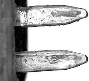
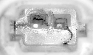
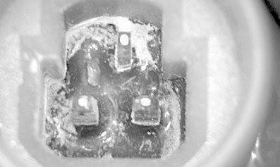
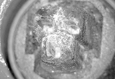
Illustrations (examples)
Worn or Corroded Terminals
Effect
Series resistance
Reduced voltage
Parallel resistance
Short between several terminals
Increased or reduced voltage
Contact is intermittent
Intermittent interruption of circuit
Burnt Terminals
Corroded Terminals
Corroded Terminals
Poorly Crimped Connection
General Information - Electrical System, Approach to Tabular Diagnostic Procedures
IMPORTANT:
Each line of the table contains a separate diagnostic step. This can be a brief description of a test or a reference to a test. The diagnostic steps should be completed in numerical order.
The tabular diagnostic procedure can consist of the following:
1. Verification of diagnostic trouble codes :
First diagnostic step to ensure that always only relevant diagnostic trouble codes are dealt with.
2. One or more preliminary checks :
Visual inspections that can be done quickly or checks of components that are easily accessible (fuses, relays, diodes, etc.).
3. All available diagnostic procedures (tests) for the system in question (component, electrical circuit, system).
IMPORTANT: If a diagnostic step (test) does not reveal any problems, the next diagnostic step in the table should be performed.
4. Additional information for the diagnosis of the affected system.
Tabular diagnostic procedure (example)
Tabular diagnostic procedure (example)
Diagnostic steps
1 Verify diagnostic trouble code
2 Preliminary test
3a - Operational check:
• Information about the test of a component/system when installed.
• If available, diagnostic addresses are offered for the test.
3b - Component check:
• Information about the test of a component when removed.
3
• Information on the location of the component and additional information.
3c - Circuit check:
• Information about the circuit test of a component/system.
3d - CAN BUS check:
• System test.
3e - Hydraulic system check:
• System test.
3f - etc.
4 a. Diagnostic schematic
4 b. Checks for intermittent faults
• Additional information for the check for intermittent faults.
4 c. Additional information:
Description
First diagnostic step to ensure that always only relevant diagnostic trouble codes are dealt with.
Visual inspections that can be done quickly or checks of components that are easily accessible (fuses, relays, diodes, etc.).
All available diagnostic procedures (tests) for the system in question (component, electrical circuit, system).
IMPORTANT: If a diagnostic step (test) does not reveal any problems, the next diagnostic step in the table should be performed.
Reference to the diagnostic schematic of the affected system:
• System overview
• Connection points
• Ground connections
Test instructions and references to information that assist in diagnosing intermittent problems.
Reference to general additional tests.
General Information - Electrical System, Troubleshooting Unsolved Problems
→NOTE:
This reference is a guideline for troubleshooting problems that still exist after standard diagnostics have been performed. These problems are usually caused by certain operating conditions, by intermittent malfunctions, or, in rare cases by a failed control unit. Depending on the situation, some or all of the following information may be of importance.
Problems caused by certain operating conditions
Review all recorded codes and consult with operator to determine operating and vehicle conditions when the problem occurs. Write down details.
1. Does code/problem occur at the same time as other problems?
2. Does code/problem occur when vehicle is warm or cold?
3. Does code/problem occur during field or transport operation?
4. Does code/problem occur while performing a specific action such as shifting, turning, braking, operating certain hydraulics?
5. When did code/problem first appear? Has service work been carried out recently? (If yes, inspect areas of maintenance for inadvertent damage or improper installations.)
Attempt to recreate code/problem based on conditions. If possible, repeat operational or system checks, electrical, hydraulic or mechanical checks under these conditions.
Problems caused by intermittent electrical failure
→NOTE:
Intermittent electrical failures are caused by wiring harness, terminal or connector problems.
1. Inspect all connectors and terminals of related circuits.
2. Check if harnesses or connectors are obstructed by mechanical parts.
3. Inspect harnesses for missing or improperly installed clamps or bands. Wiring harnesses that are too loose or too tight can cause worn or damaged cables.
4. Inspect mechanical linkages for proper operating condition.
Problems caused by failed control units
→NOTE:
Before replacing control unit, review all tests. Control units are the least likely cause of failure!
1. If all checks have been performed and no problems have been identified, check the power supply circuit and ground circuit. Power supply inputs must not deviate from battery voltage by more than 1 volt, and ground circuits must have a resistance of less than 1.0 ohm in relation to the ground point of the vehicle.
2. Inspect all connectors and terminals of associated control units.
General Information - Electrical System, Worksheet for Circuit/Harness Test
Circuit tests must be carried out if component testing on an electrical component in the circuit fails to identify a problem and:
active diagnostic trouble codes indicate there is a problem in the relevant circuit. saved diagnostic trouble codes that indicate a problem in the relevant circuit keep re-appearing. problems occur with a function associated with the relevant circuit.
→NOTE:
In the event of occasional circuit problems (loose contacts), it may be possible to use the beep mode of the relevant control unit to identify the fault. All the circuits of components that are marked “BEEP” in the Summary of Addresses for the relevant control unit can be checked using the beep mode of the control unit. For more information on the beep mode, see “Test Procedure in the Event of Occasional Problems” for the relevant control unit in the Group of the relevant circuit in Section 240.
The worksheet below allows circuits to be checked logically, with the technician naming all the relevant components and noting the steps taken. The list can be used to prove what work has been done; if the problem cannot be solved, the worksheet may be requested by the relevant after-sales service office.
Worksheet for circuit diagnosis
Worksheet for circuit/harness diagnosis
General Information
Dealer: Postal address:
Thirteen-digit tractor serial number:
Operating
Existing
2.) Check the leads and plug connections
Harness can be checked in diagnostic mode: YES/NO
Connector no.: Harness no.:
Result of check Further comment
Number:
Have the electrical connections been checked for bad, loose, widened, slid-back or corroded contacts? YES/NO
Connector no.: Harness no.:
Number:
Have the electrical connections been checked for bad, loose, widened, slid-back or corroded contacts? YES/NO
Connector no.: Harness no.:
Number:
Have the electrical connections been checked for bad, loose, widened, slid-back or corroded contacts? YES/NO
Connector no.: Harness no.:
Number:
Have the electrical connections been checked for bad, loose, widened, slid-back or corroded contacts? YES/NO
Other remarks:
General Information - Electrical System, Visual Check
If a customer reports a problem, perform a visual check of the electrical system before starting the tractor.
[1] - Check for frayed leads.
[2] - Check for missing or worn insulation; this can point to a wiring problem.
[3] - Check for loose or broken connections and leads:
[4] - Check battery for:
Loose or corroded terminal connections
Loose cable clamps/ties or battery posts
Dirt
Moisture
Cracked case
Correct electrolyte level
[5] - Check the alternator belt tension.
[6] - Check for overheated components five minutes after the engine has been shut off. Often there will be the smell of burnt insulation. Place your hand on the alternator. The presence of heat after the engine has been off for some time is a sure sign of a charging circuit problem.
[7] - If the visual check does not isolate a possible problem, but the results do not indicate that the engine should not be started, turn the ignition key to the IGN position. Check the accessory circuits, indicator lights, etc. Do these individual parts work? Look for sparks or smoke as signs of shorts.
[8] - Start the engine. Check all indicators for proper operation; determine if the system is charging or discharging.
[9] - In short, check for any abnormal conditions.
Many electrical faults cannot be identified easily even when the engine is started. For this reason the electrical system should be systematically and completely checked.
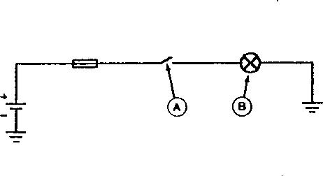
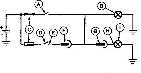
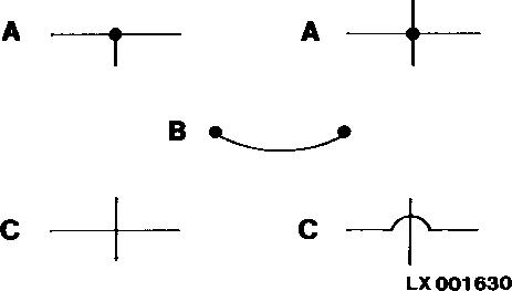
General Information - Electrical System, Electrical Circuit Malfunctions
Electrical circuit malfunction areas
Other malfunctions
There are only four circuit malfunctions:
High-resistance circuit ( GO TO 1 ).
Open circuit ( GO TO 1 ).
Grounded circuit ( GO TO 2 ).
Shorted circuit ( GO TO 3 ).
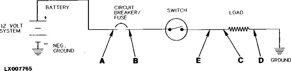
There are only three sections in a simple circuit where these malfunctions occur: Before the controlling switch (A), between the controlling switch (A) and the load (B), and after load (B).
Component malfunctions can easily be confused with circuit malfunctions. Therefore, care must be exercised when isolating the cause of the problem.
Example: A component does not operate before disconnecting an electrical connection, but it operates after reconnecting the connector. Cause: High resistance created a voltage drop at the connector terminals resulting in insufficient power supply to the component.
Types of fault
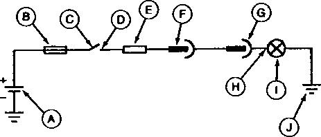
( 1 ) High resistance or open circuit
Action:
High resistance or open circuit
LEGEND:
Battery
Fuse
Switch
Component terminal
Circuit resistance
Circuit connector
Circuit connector
Component terminal
Lamp
Ground
terminals, wire gauge too small or partially broken leads).
An open circuit results in no component operation because the circuit is incomplete (e.g. broken lead, terminals disconnected, open protective device on switch).
To isolate the location of a "high resistance" or "open circuit":
[1] - Turn controlling switch (C) ON and connect load (I) to the circuit. Check the voltage at an easily accessible point between (D) and (H).
If voltage is low, move toward voltage source (A) to locate point of voltage drop.
→NOTE:
The example shows high resistance between (D) and (F) and an open circuit between (F) and (G).
If voltage is correct, move toward load (I) and ground terminal (J) to locate voltage drop.
[2] - Repair as required.
Result:
NO:Repeat test procedure after repair.
YES:See procedure for grounded circuit: GO TO 2 . See procedure for shorted circuit: GO TO 3 .
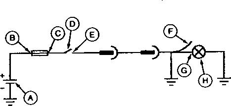
( 2 ) Grounded circuit
Action:
Grounded circuit
LEGEND:
A Battery
B Fuse terminal C Fuse terminal D Switch
E Component terminal
F Grounded circuit G Component terminal
H Lamp
A grounded circuit results in no component operation and opening of the fuse or circuit breaker (e.g. power lead contacting ground).
To isolate the location of a grounded circuit:
[1] - With controlling switch (D) OFF, check for continuity to ground between (C) and (D).
If there is continuity, there is a grounded circuit between (C) and (D). Repair circuit.
If there is no continuity, go to step 2.
[2] - Disconnect load (H) at (G).
[3] - With controlling switch (D) OFF, check continuity to ground between (D) and (F).
If there is continuity, there is a grounded circuit between (E) and (F). Repair circuit.
→NOTE:
In this example, the circuit is grounded between (E) and (F).
Result:
NO:Repeat test procedure after repair.
YES:See procedure for shorted circuit: GO TO 3 .
( 3 ) Shorted circuit
Action:
Shorted circuit
LEGEND:
Switch
Lamp
Fuse
Switch
Component terminal
Circuit connector
Circuit connector
Component terminal
Lamp
A shorted circuit usually results in two components operating even though only one of two switches is turned on (e.g. improper wire-to-wire contact). Components can also become shorted. However, shorted components will usually open the circuit protection device.
To isolate the location of a shorted circuit:
[1] - Turn switch (A) ON for correct lamp (B) to operate.
[2] - Start at controlling switch (D) of lamp (I) that should not be operating and disconnect the wire at terminal (E).
[3] - Follow circuit and disconnect wire at connectors (F, G or H) until lamp (I) stops operating.
[4] - The short or improper connection must be between the last two locations where the wire was disconnected. In this example, it is between (F) and (G).
[5] - Repair circuit as follows:
Wires not in an insulating tube: Wrap individual wire with electrical tape or replace the damaged wire and band as required.
Wires in an insulating tube: If hot spots exist in shorted area of the insulating tube, replace harness. If hot spots are not noticeable, install a new wire of proper gauge between the last two connections. Band wire to outside of harness.
Result:
NO:Repeat test procedure after repair.
General - Electrical System, Test for Open Circuit under Load
→NOTE:
With the tester, the electrical line and the connector is tested for an open circuit and high resistance with and without load.
Use JDG11668 to perform load tests on circuits. JDG11668 allows approximately 4.0 A of a 12 V MAX circuit to flow in the circuit while the test is being performed.
CAUTION:
JDG11668 tool can get warm if the apply load switch is pressed for several minutes. The load should only be on long enough to make voltage measurement.
Circuit test with the electric load tester
→NOTE:
Required tools:
1. Digital Multimeter
2. JDG10466 – Flex Probe Kit
3. JDG11668—Electric Load Tester
For further information, see SERVICEGARD™ online catalog or contact your John Deere dealer.
Testing a good circuit:
A Control Unit
B Control Unit Connector
C Connection Point
D Solenoid Electrical Connectors
E Solenoid
F Battery
G Jumper Lead with 6A Fuse
H Flex Probe
I Multimeter
J Electric Load Tester
K Flex Probe
Testing a bad circuit:
Load-Testing a Bad Circuit
LEGEND:
A Control Unit
B Control Unit Connector
C Connection Point
D Solenoid Electrical Connectors
E Solenoid
F Battery
G Jumper Lead with 6A Fuse
H Flex Probe
I Multimeter
J Electric Load Tester
K Flex Probe
L Defect in Circuit
1. Disconnect connector (B) from component (A) and connector (D) from component (E).
2. Connect the lead (G) at the positive terminal of the battery and at the connector of the control unit (B).
3. Connect the measuring lines of the multimeter (I) with the tester (J).
4. Connect the black lead of the tester (J) to the negative terminal of the battery (F).
5. Connect the red lead of the tester (J) with the probe (K) at connector (D).
6. Note and record voltage at multimeter (I) before pressing the button for applying the load.
7. Press button on JDG11668 to apply load. Note and record voltage at multimeter (I) while the button is pressed.
8. METER READING (before applied load) - METER READING (with applied load) = RESULT . When the load is applied, the result should not be more than 3.0 V. If the difference > 3.0 V, the circuit (or wire segment) is not OK.
Test the supply voltage lead of a control unit with the electric load tester.
Test the supply voltage lead of a control unit with the electric load tester. LEGEND:
1. Disconnect connector (B) from control unit (A).
2. Connect the measuring lines of the multimeter (G) with the tester (H).
3. Connect the black lead of the tester (H) to the negative terminal of the battery (F).
4. Connect the red lead of the tester (H) with the probe (E) at connector (B).
5. Note and record voltage at multimeter (G) before pressing the button for applying the load.
6. Press button on JDG11668 to apply load. Note and record voltage at multimeter (G) while the button is pressed.
7. METER READING (before applied load) - METER READING (with applied load) = RESULT . When the load is applied, the result should not be more than 3.0 V. If the difference > 3.0 V, the circuit (or wire segment) is not OK.
Test the ground connection of a control unit with the electric load tester (vehicle ground or ground point).
Test the ground connection of a control unit with the electric load tester (vehicle ground or ground point).
LEGEND:
Control Unit
Control Unit Connector
Connection Point
Multimeter
Electric Load Tester
1. Disconnect connector (B) from control unit (A).
2. Connect the measuring lines of the multimeter (E) with the tester (G).
3. Connect the black lead of the tester (G) to the positive terminal of the battery (F).
4. Connect the red lead of the tester (G) with the probe (D) at connector (B).
IMPORTANT: Make sure that the flexible probe (D) is connected at the ground pin of the control unit connector (B).
5. Note and record voltage at multimeter (E) before pressing the button for applying the load.
6. Press button on JDG11668 to apply load. Note and record voltage at multimeter (E) while the button is pressed.
7. METER READING (before applied load) - METER READING (with applied load) = RESULT . When the load is applied, the result should not be more than 3.0 V. If the difference > 3.0 V, the circuit (or wire segment) is not OK.
Test the ground connection of a component with the electric load tester (vehicle ground or ground point).
Test the ground connection of a component with the electric load tester (vehicle ground or ground point).
LEGEND:
Control Unit
Control Unit Connector
Connection Point
Connector of the Component
Component
Battery
Multimeter
Flex Probe I Electric Load Tester
IMPORTANT:
This measuring method is only for components that are connected directly to vehicle ground. Do not use this measuring method to test components that are grounded by means of a control unit.
1. Disconnect connector (D) from component (E).
2. Connect the measuring lines of the multimeter (G) with the tester (I).
3. Connect the black lead of the tester (I) to the positive terminal of the battery (F).
4. Connect the red lead of the tester (I) with the probe (H) at connector (D).
IMPORTANT: Make sure that the flexible probe (H) is connected at the ground pin of the component connector (D).
5. Note and record voltage at multimeter (G) before pressing the button for applying the load.
6. Press button on JDG11668 to apply load. Note and record voltage at multimeter (G) while the button is pressed.
7. METER READING (before applied load) - METER READING (with applied load) = RESULT . When the load is applied, the result should not be more than 3.0 V. If the difference > 3.0 V, the circuit (or wire segment) is not OK.
General Information - Electrical System, Seven-Step Test Procedure
Electrical test procedure
LEGEND:
Battery side of circuit breaker B Load side of circuit breaker/input of switch C Output of switch/Input of load
Output of load
Lead
Electrical test procedure
Step 1 Switch OFF
Check battery side (A) of the circuit breaker for battery voltage
Step 2 Switch OFF
Check load side (B) of the circuit breaker for battery voltage
Step 3 Battery disconnected, switch OFF
Check load side (B) of the circuit breaker for continuity to ground
Step 4 Battery connected, load disconnected, switch ON
Check output (C) of the switch for battery voltage
Step 5 Battery disconnected, load disconnected, switch ON
Check output (C) of the switch for continuity to ground ..........
Step 6 Battery connected, load connected, switch ON
Check input (C) of the load for battery voltage
Step 7 Battery disconnected
Check output (D) of the load for continuity to ground
Battery voltage normal: Go to step 2.
Battery voltage too low: Check lines and connectors. Repeat step 1.
Battery voltage normal: Go to step 4.
Battery voltage too low: Check lines, connectors, and circuit breaker. Go to step 3.
Battery voltage too low: Check lines, connectors, and switch. Go to step 5.
No voltage: Repair or replace switch.
Resistance high: Go to step 6.
Resistance low: Check lines, connectors, and switch. Go to step 5.
Battery voltage normal: Circuit OK.
Battery voltage too low: Check lines, connectors, and load. Go to step 7.
No voltage: Repair or replace load.
Resistance low: Circuit OK.
Resistance high: Check lines and connectors. Repeat step 7.
General Information - Hydraulic System, Symbols in Circuit Diagrams
Lines
Hydraulic symbols—lines
Valves
Hydraulic symbols valves
→NOTE:
LEGEND:
A Oil line or passage
B Control line
C Sub-assembly enclosure
D Mechanical connections (e.g. shafts)
LEGEND:
A With one operating position
B With two operating positions
C With three operating positions
D 3/2 directional control valve
When designating a valve such as the 3/2 directional control valve (D), the first figure indicates the number of connections, and the second the number of operating positions.
A Pilot pressure preset by a spring B Pilot pressure controlled by pilot line
LEGEND: A Constant B Adjustable
LEGEND: A Single-acting
LEGEND:
Hydraulic symbols—hydraulic motor
Filter or screen
Hydraulic symbols filter or screen
Cooler
Hydraulic symbols—cooler
Line connections and junctions
Hydraulic symbols connections and junctions
Connections
Hydraulic symbols connections
LEGEND: A Line connections B Hose C Line junctions
LEGEND: A Quick-coupler B Test port
Hydraulic symbols reservoir
Sensors
Hydraulic symbols—sensors
Electrical leads
Hydraulic symbols electrical leads
LEGEND:
A Open (sump)
B Under pressure
LEGEND: A Pressure sensor B Temperature sensor
C Pressure switches
General - Regions and Country Versions
Regions
LEGEND:
Region 1 China, India, South and East Asia, Africa except for North Africa
Region 2 Europe, GUS States including Russia, North Africa, Near and Middle East
Region 3 South America, Central America
Region 4 North America, Australia, New Zealand
Tractors in Regions 1, 2 and 3 are equipped with ECE (ECONOMIC COMMISSION FOR EUROPE) electrical systems.
Tractors in Region 4 are equipped with SAE (SOCIETY OF AUTOMOTIVE ENGINEERS) electrical systems.
→NOTE:
The main difference between ECE and SAE electrical systems is the turn-signal light. Tractors with SAE electrics have the turn-signal lights mounted in the cab roof. The turn-signal lights operate in different ways. With SAE electrics, the turn signal flashes on the side selected, while the light on the opposite side comes on but does not flash. With ECE electrics, all that happens is that the turn signal flashes on the side selected.
There is one more difference concerning the lighting system. Tractors with ECE electrics have parking lights while those with SAE electrics do not.