Edition no. 8 ©BLS – Brännehylte Lagersystem AB. 251126
About these instructions
Read the entire manual before starting assembly. Follow the directions in the manual to make sure the product complies with current standards.
The purpose of these assembly instructions is to facilitate correct installation and to inform of risks and how to avoid them. Bear in mind that the instructions are for your safety and the safety of others.
Use the assembly instructions and instructions for use in conjunction with:
* assembly
* regular inspections (together with the periodic inspection template)
* taking corrective action as directed
Each installation must be provided with a load sign located in a clearly visible place.
Perform regular checks to ensure the technical safety of the tyre racking. Examples of protocols for periodic pallet racking inspections are available on our website www.blsab.se.
Parts of the installation instructions and instructions for use refer to the Swedish Standard SS-EN 15635:2008 - Steel static storage systems – Application and maintenance of storage equipment. If necessary, the purchaser or user can obtain the above standard from SIS. See www.sis.se for further information.
Links for downloading BLS assembly instructions & instructions for use can be found at www.blsab.se
If in doubt, or for further information, please contact Brännehylte Lagersystem: CONTACT US
Telephone
Email Website
Postal address
Street address
+46 370 30 50 00
info@blsab.se www.blsab.se
P.O. Box 12, SE 335 04 Hillerstorp, Sweden
Brännehylte Lagersystem AB
High Chaparral
SE 335 96 Kulltorp, Sweden
Before you begin
Recommended tools
Other useful tools:
-Chalk line -Allen key, 6 mm -Adjustable spanner -Vacuum cleaner
List of supplied fasteners
Self-drilling screw
5.5×19 part 111616-4-19
M8×20 M10×20 M10×25 part 111308-1-20-7 part 111310-1-20-7 part 111310-1-25-7
M10×75
M10×130
75 mm - part 111310-1-75-7 130 mm - part 111310-1-130-7
Underlying surface
The client/user must make sure the floor is able to bear the relevant loads.
Anchoring
Tyre racks must be anchored to the floor to prevent the uprights from moving when using mechanical handling equipment in or near warehouse fixtures.
Safety
Correct rack assembly is essential for a safe structure. Assembly must be carried out professionally and in accordance with these instructions.
We recommend that several people take part in the erection and completion of the racking in order to facilitate and ensure safe installation.
Scissor lifts may be used during assembly, depending on the height and number of levels in the installation.
M8 / M10 nut with flange part 111308-7-0-7 part 111310-8-0-7 M10 nut lock part 111310-6-0-7
Fasteners not included
U-bolt M8 part 111403-08
Distance tube 30 30 mm - part 111056
Sleeve nut M8×30 part 111308-13-0-7
Base plate XL Low C90 - part 90-006
Multi-Monti 10×80 part 111009-14
Bracing diagram


Inspection & Maintenance
Assembly inspections
Inspect the assembly before putting the tyre racking into service to make sure the assembly instructions were followed.
Upgrades and disposal
In the event of redeployment, upgrades or relocation of the storage system, contact BLS AB.
Daily inspections
Inspect the tyre racking daily to make sure components affecting load-bearing capacity are undamaged. Replace damaged loadbearing parts immediately. Other parts may be repaired.
Periodic inspections
By law, in addition to self-inspection, the shelves must be checked by a technical expert at least once a year to make sure it complies with assembly instructions.
Visual inspections
Perform a visual inspection to gain a first impression of the condition of the racking. If the load is well ordered and the tyre racking appears entire, it may be assumed to function well even in terms of safety. Should multiple arms, uprights or braces be deformed or impact damaged, a more thorough inspection will be required.
Deformed arms
To prevent damage, correct any deformation due to misshapen fasteners. For safety reasons, the tyre racking is designed to store tyres by means of two or three arms.
Deformed bracing members
Horizontal and diagonal braces are often struck when goods are being loaded, especially if the racking is served by forklift. Thus, check the locations where braces are fastened. If diagonal braces are deformed, they must be straightened and tensioned. Replace horizontal braces if they show any sharp creases after impact. Straighten longitudinally deformed braces.
Rectify any damage caused by e.g. collisions immediately! A damaged upright or arm is a safety hazard.
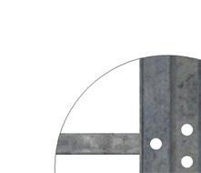
Detailed overview
1. Frame 2. Tyre beam floor 3. Tyre beam
4. Back cross
5. Tyre stop
6. Upright protector
7. Frame barrier
8. Safety mesh
Single rack
Installing frames
1. Installing upright base plates. (A)
2. Locate the braces according to the bracing diagram on page 5. (B)
3. Place distance tubes at single braces at the ends of the frame. (C)
4. Tighten the braces.
B B A A B B
M10×75
Installing tyre beams
1. Position end plates at the desired height intervals. (D)
2. Fasten the end plates using M10×20 bolts and M10 nuts with ribbed flanges. Two bolts per upright. (E)
The end plates have a 50 mm hole separation, allowing tiers with multiples of this value. (Option 1 and Option 2)
3. Raise the frames one at a time and then fasten them to each other using the tyre beam. (F)
Because the frames may lean initially, they must be plumbed to max H/350 or max 20 mm in the transverse and longitudinal rack directions
2 pcs M10 with flange
2 pcs M10×20
End plate tyre beam (level 2, 3 and above)
– Five holes for attachment
Option 2 Option 1
4. Fasten the tyre beam to each end plate using two M10×130 bolts and M10 ribbed flange nuts. (G) The end plates have a 50 mm hole separation, allowing tiers with multiples of this value.
5. Install other beam levels at the desired height intervals. (H)
2 pcs M10×130
2 pcs M10 with flange
Däckbalk Enkel
Installing floor beams
Install floor beams in the same way as the other beam levels. (I)
Note the difference between the floor beam end plates compared to the other beam levels.
2 pcs M10×130
2 pcs M10 with flange
Installing tyre holders
1. Install tyre holders on the tyre beams using M8 U-bolts and M8×30 sleeve nuts. (J)
2. The number of tyre sets that can be stored depends on the tyre beam model and its length. Each set of tyres must be supported by at least two tyre holders.
From tyre beam level 4, we recommend three tyre holders for greater stability. (K)
For racks with forklift aisles, always use three tyre holders at every tyre beam level. (L)
Adjust the location of tyre holders to suit the selected configuration; see instructions (Page 15)
Sleeve nut 2 pcs M8×30 U-bolt M8
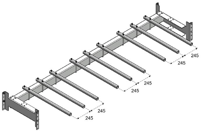
3. Fit three deck holders to tyre beam level 4 and above to facilitate safe loading and unloading. Centre the third holder between the two existing holders according to the dimensions above
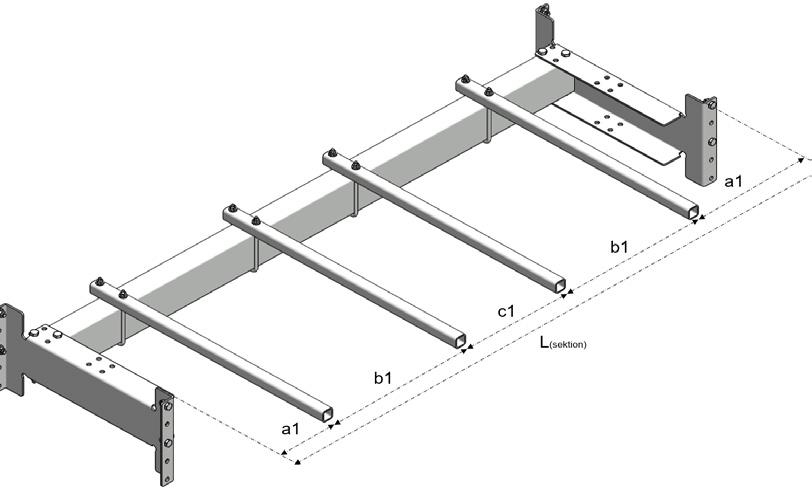
*1450 mm – Intended for tyres ≤ 725 mm **1600 mm – Intended for tyres ≤ 800 mm
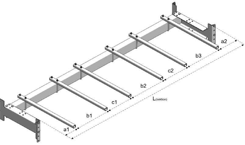
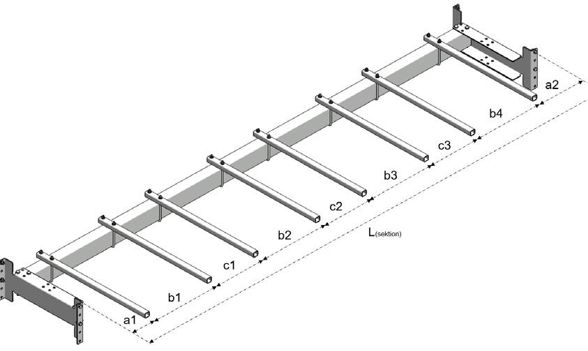
*2225 mm – Intended for tyres ≤ 725 mm
**2400 mm – Intended for tyres ≤ 800 mm
*2900 mm – Intended for tyres ≤ 725 mm
**3200 mm – Intended for tyres ≤ 800 mm
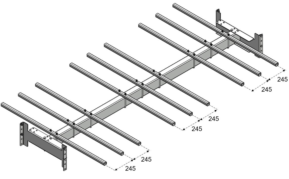
Tables and figures show the recommended positions and distances between tyre holders along the tyre beam. The same locations and dimensions apply to single and double racks. The illustrations show single tyre beams.
3-sets
4-sets
Installing cross bracing
Stabilise the tyre racking against longitudinal sway by means of bracing straps and bottle screws. Install the cross bracing between beam levels 2 and 3.
Do not cross brace other beam levels.
1. Fasten a bottle screw and bracing straps to each upright. Locate the bracket next to the nearby tyre beam with end plate. (M)
2. Fasten the bracket to the upright using 2 pcs M10×20 bolts and 2 pcs M10 nuts with ribbed flanges. (N)
3. Fasten the bracing straps and bottle screw using M10×25 bolts and M10 nuts with ribbed flanges. (O + P)
MIn single tyre racks, attach the bracing strap bracket to the frame.
Bracing strap Bottle screw
Bracket
4. The choice of cross bracing straps between tyre levels 2 and 3 in the racking depends on the model, tyre beam length and the distance between the tyre beams.
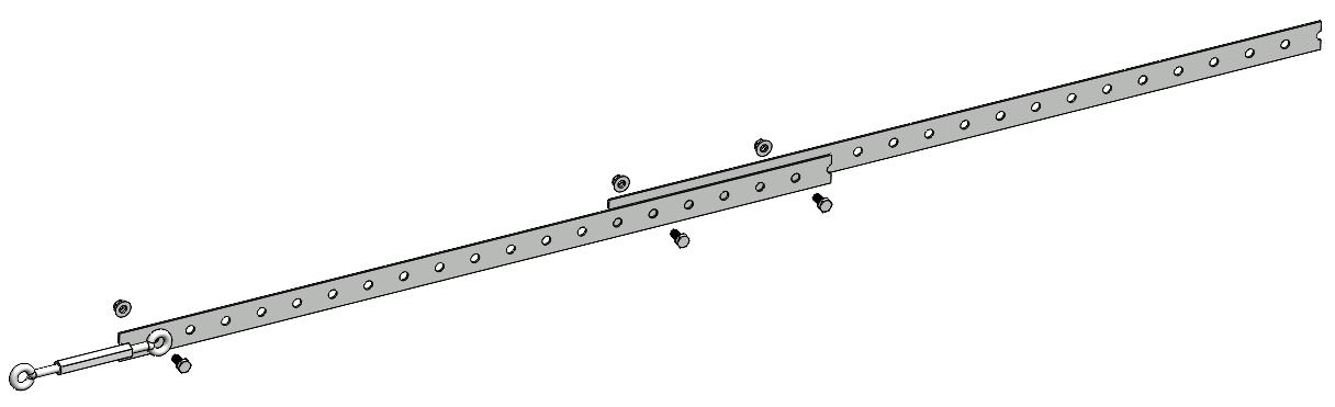
BLS bracing straps are available in lengths of 1 and 3 metres; to achieve the appropriate length, join them using M10×20 and M10 nuts with ribbed flanges. (Q)
Illustration of splicing with a 1 + 1 m strap for 1450 or 1600 mm sections: Tyre beam / section length
QBracing strap use per cross brace
2 pcs M10 with flange
2 pcs M10×20
M10 with flange
Anchoring tyre racks to the floor
Anchoring forms an essential structural component and must be carried out as directed, in order to ensure a safe, stable rack.
1. Use Multi-Monti M10×80 for anchoring to the floor.
Use four bolts for each frame plate. (R)
Pre-drill the concrete with a Ø8 mm masonry bit.
Multi Monti
Multi Monti
Double rack
Installing frames
1. Installing upright base plates. (A)
2. Locate the braces according to the bracing diagram on page 5. (B)
3. Place distance tubes at single braces at the ends of the frame. (C)
4. Tighten the braces.
B B A A B B
M10×75
Installing tyre beams
1. Position end plates for the desired height separation. (D)
2. Fasten the end plates using M10×20 bolts and M10 nuts with ribbed flanges. Two bolts per upright. (E)
The end plates have 50 mm hole spacing, allowing tiers with multiples of this value. (Option 1 and Option 2)
Option 1
beam frames (levels 2, 3 and above) –
Option 2
3. Raise the frames one at a time and then fasten them to each other using the tyre beam. (F)
Because the frames may lean initially, they must be plumbed to max H/350 or max 20 mm in the transverse and longitudinal rack directions
M10×20
Tyre
Five holes for attachment
4. Fasten the tyre beam to each end plate using two M10×130 bolts and M10 ribbed flange nuts. (G + H)
Install the bracing strap bracket at the same time.
On tyre beam level 2, install the bracket with the square hole facing up. (G)
On tyre beam level 3, install the bracket with the round hole facing down. (H)
Install tyre beams on levels 4 and above without bracing strap brackets.
HGbracket
2 pcs M10×130
2 pcs M10 with flange
Bracing strap
with square hole
Tyre beam, level 2
Tyre beam, level 3
Tyre beam, level 4
2 pcs M10 with flange
2 pcs M10×130
Tyre beam, level 5
Floor beam, level 1
Bracing strap bracket with round hole
Installing floor beams
Install floor beams in the same way as beams on other levels. (K)
Note the difference between the floor beam end plates compared to the other beam levels.
2 pcs M10×130
K2 pcs M10 with flange
End plate floor beam level 1 – Three holes for attachment
Floor beam, level 1
Tyre beam, level 2
Tyre beam, level 3
Tyre beam, level 4
Tyre beam, level 5
Installing tyre holders
1. Install the tyre holders on the tyre beams using M8 U-bolts and ribbed M8×30 nuts. (L)
2. The number of tyre sets that can be stored depends on the tyre beam model and its length. Each set of tyres must be supported by at least two tyre holders.
From tyre beam level 4, we recommend three tyre holders for greater stability. (M)
For racks with forklift aisles, always use three tyre holders at every tyre beam level. (N)
Adjust the location of the tire holders to suit the selected configuration – see instructions (Page 26)
Sleeve nut 2 pcs M8×30
U-bolt M8
Floor beam, level 1
Tyre beam, level 2
Tyre beam, level 3
Tyre beam, level 4
Tyre beam, level 5
3. Fit three deck holders to tyre beam level 4 and above to facilitate safe loading and unloading. Centre the third holder between the two existing holders according to the dimensions above
*1450 mm – Intended for tyres ≤ 725 mm **1600 mm – Intended for tyres ≤ 800 mm
3-sets
*2225 mm – Intended for tyres ≤ 725 mm
**2400 mm – Intended for tyres ≤ 800 mm
*2900 mm – Intended for tyres ≤ 725 mm
**3200 mm – Intended for tyres ≤ 800 mm
*Tables and figures show the recommended positions and distances between tyre holders along the tyre beam. The same locations and dimensions apply to single and double racks. The illustrations show single tyre beams.
4-sets
Installing cross bracing
Stabilise the tyre racking against longitudinal sway by means of bracing straps and bottle screws. Install the cross bracing between tyre beam levels 2 and 3.
Do not cross brace other beam levels.
1. Attach the bottle screws and bracing straps using the brackets in the respective tyre beams. (O)
2. Fasten the bracing straps and bottle screw using M10×25 bolts and M10 nuts with ribbed flanges to the bracing strap bracket on tyre beam level 2. (P)
3. Fasten the bracing straps using M10×20 bolts and M10 nuts with ribbed flanges to the bracing strap bracket on tyre beam level 3. (Q)
Tyre beam, level 2
Tyre beam, level 3
Tyre beam, level 4
Tyre beam, level 5
Floor beam, level 1
Bracing strap bracket for double tyre ranking attaches to the tyre beam.
Bracing strap Bottle screw
Bracket
4. The choice of cross bracing straps between tyre levels 2 and 3 in the racking depends on the model, tyre beam length and the distance between the tyre beams.
BLS bracing straps are available in lengths of 1 and 3 metres; to achieve the appropriate length, join them using M10×20 and M10 nuts with ribbed flanges. (R)
Bracing strap use per cross brace
Illustration of splicing with a 1 + 1 m strap for 1450 or 1600 mm sections:
2 pcs M10 with flange
2 pcs M10×20
M10 with flange
Bottle screw
M10×25
Anchoring tyre racking to the floor
Anchoring forms an essential structural component and must be carried out as directed, in order to ensure a safe, stable rack.
1. Use Multi-Monti M10×80 for anchoring to the floor.
Use four bolts for each frame plate. (S)
Pre-drill the concrete with a Ø8 mm masonry bit.
Multi Monti
Multi Monti
pcs M10×80
Installing frame barriers
Frame barrier, single rack
Frame barriers, double rack
2 pcs Allen screws M8×30
4 pcs Multi-Monti 10×80 Expander bolt 10×90
2 pcs Allen screws M8×110
2 pcs Allen screws M8×110
2 pcs M8 with flange
Floor bracket Profile End caps Joint
Installing tyre stops
4 pcs self-drilling screws
5.5×19
4 pcs self-drilling screws
5.5×19
Installing safety mesh
Safety mesh, single rack
Safety mesh, double stand
B
2 pcs Upright brackets
2 pcs Zero offset brackets
2 pcs Zero offset brackets
4 pcs Splice brackets
Installing load signs
At least one load sign per rack must be clearly visible.