The Need for Community Space
Connectivity
Create a network of inter-connected open spaces


Participation

Involves local Residents to participate in community activities
Integration Combining water edge with green spaces and built spaces
Multi-function

Provide multi-function spaces for varied activities which involves large group of people
Development Opportunities
1. Community Centre
2. Public Plazas
3. Playgrounds
4. Cultural Hub
5. Water Sports
6. Ferry- Terminal Rejuvination

7. Recreational Spaces
Shared Water-edge
1. Enhancement of open space concepts


2. Design infrastructure to minimalise barriers
3. Retain the visual connections of the Blue’s Point Reserve


4. Improve the water edge
5. Improves the quality of existing natural landscape features
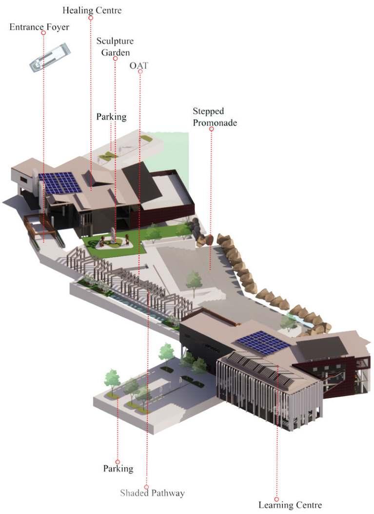
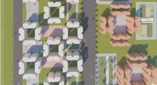
The above figure shows the major view-points from the site -

4
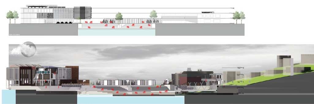
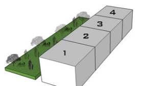
Fig.1 Proposed Master Plan and Sections of Lavender Bay
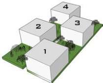
site was divided into 4 parts having an Art Gallery, Co-working space, Community centre and a sports centre catering to the residents of Lavender Bay area and North Sydney.
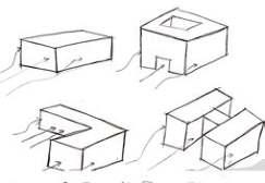
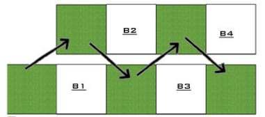
Fig.2 Proposed Massing near Blue’s Point Reserve Fig.3 Conceptual Community spaces
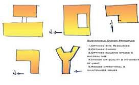
Fig.4 Conceptual Massing on site and Conceptual section
Blue’s Point Reserve


5
Fig.5 Site Analysis


6
Fig.6 SWOT Analysis of the Site
Fig.8 Form development of Learning Centre
Fig.9 Spatial organisation for Learning centre according to functional needs
Fig.10 Spatial organisation for Aquatic centre according to functional needs
Fig.7 Conceptual design for Built blocks
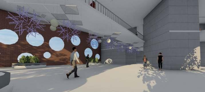
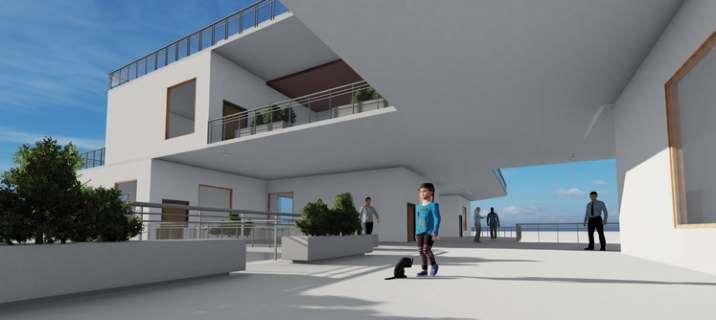
Blue’s Point Reserve Community centre - The contonured site setting at the edge, sets the space for a relaxed setting. One would experience an awe of the Harbour bridge along with Opera House, the knowledge centre on the edge of the water body, sets the space for relaxed learning space and calmness to learn and understand new things, while on the other end the aquatic centre which is a physical healing space utilises the existing water from Blues bay, making it a natural pool and fresh water being used for the user.

7
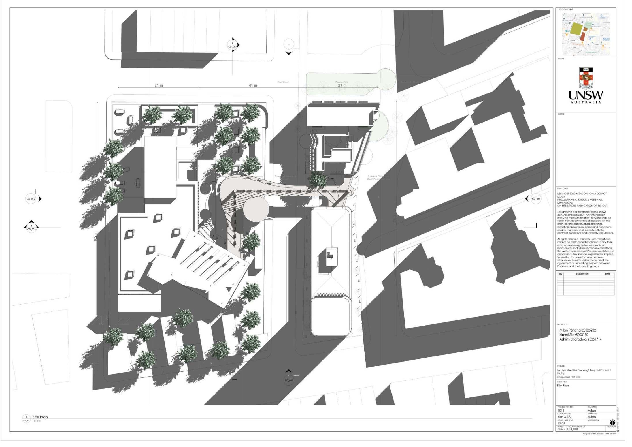
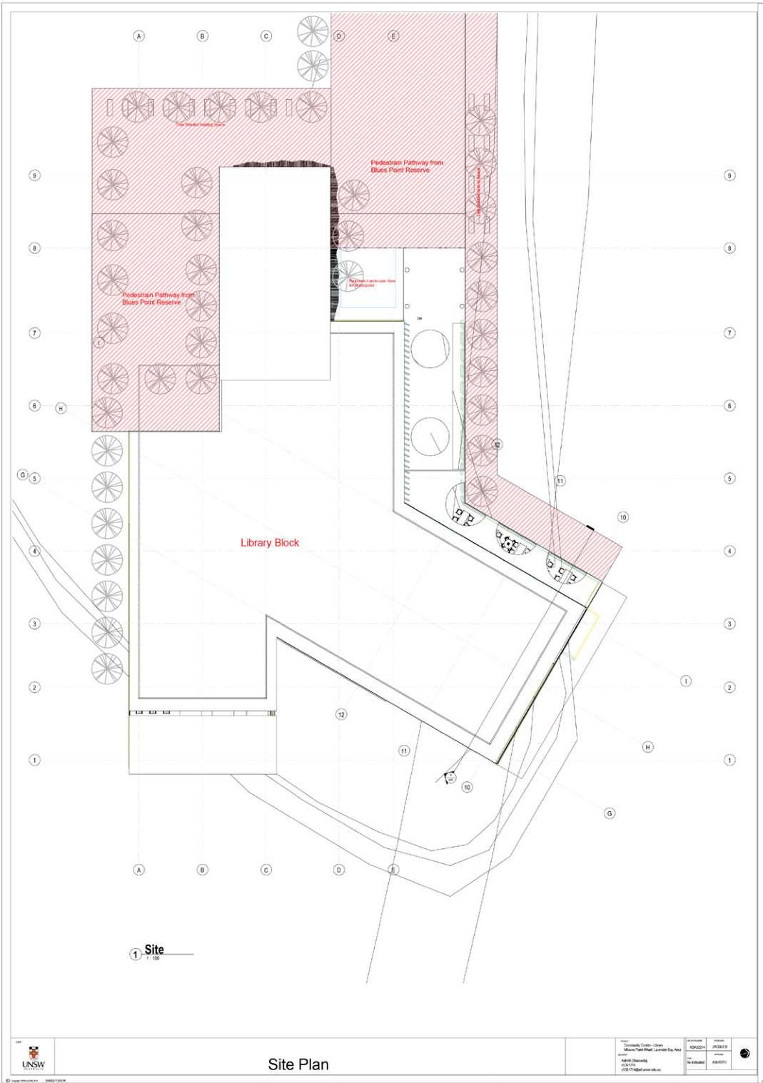
Fig.11 Site Plan
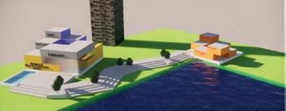
Fig.12 3D schematic View of the Site
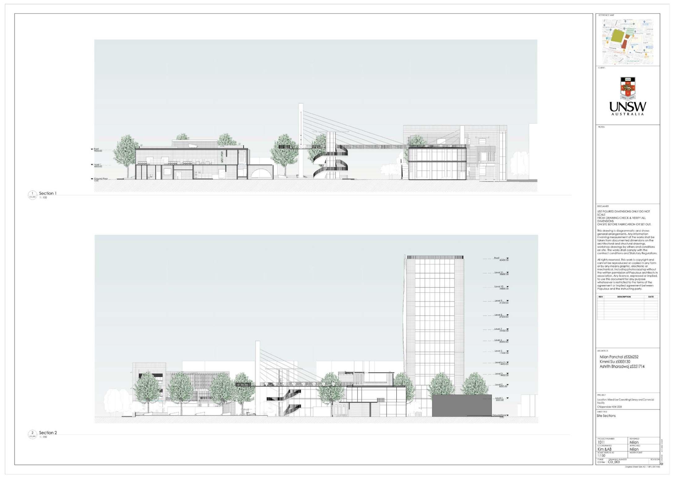
Fig.13 Site Section


8
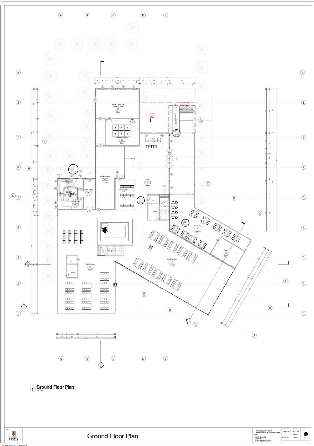
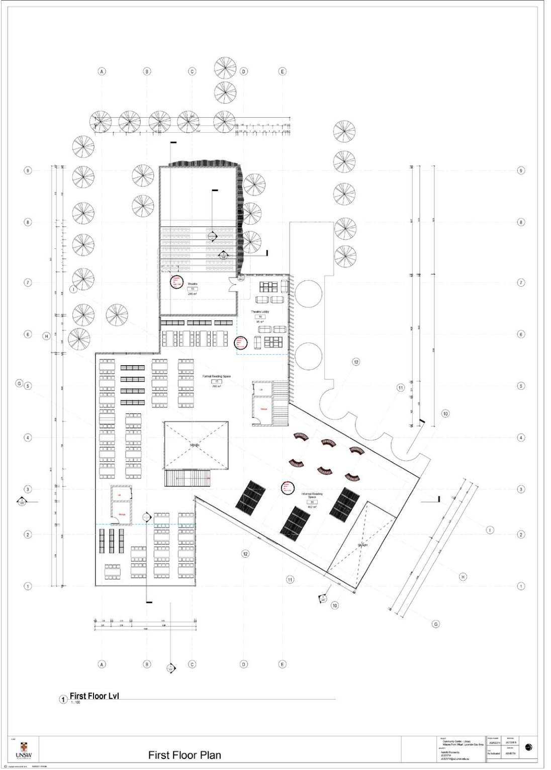
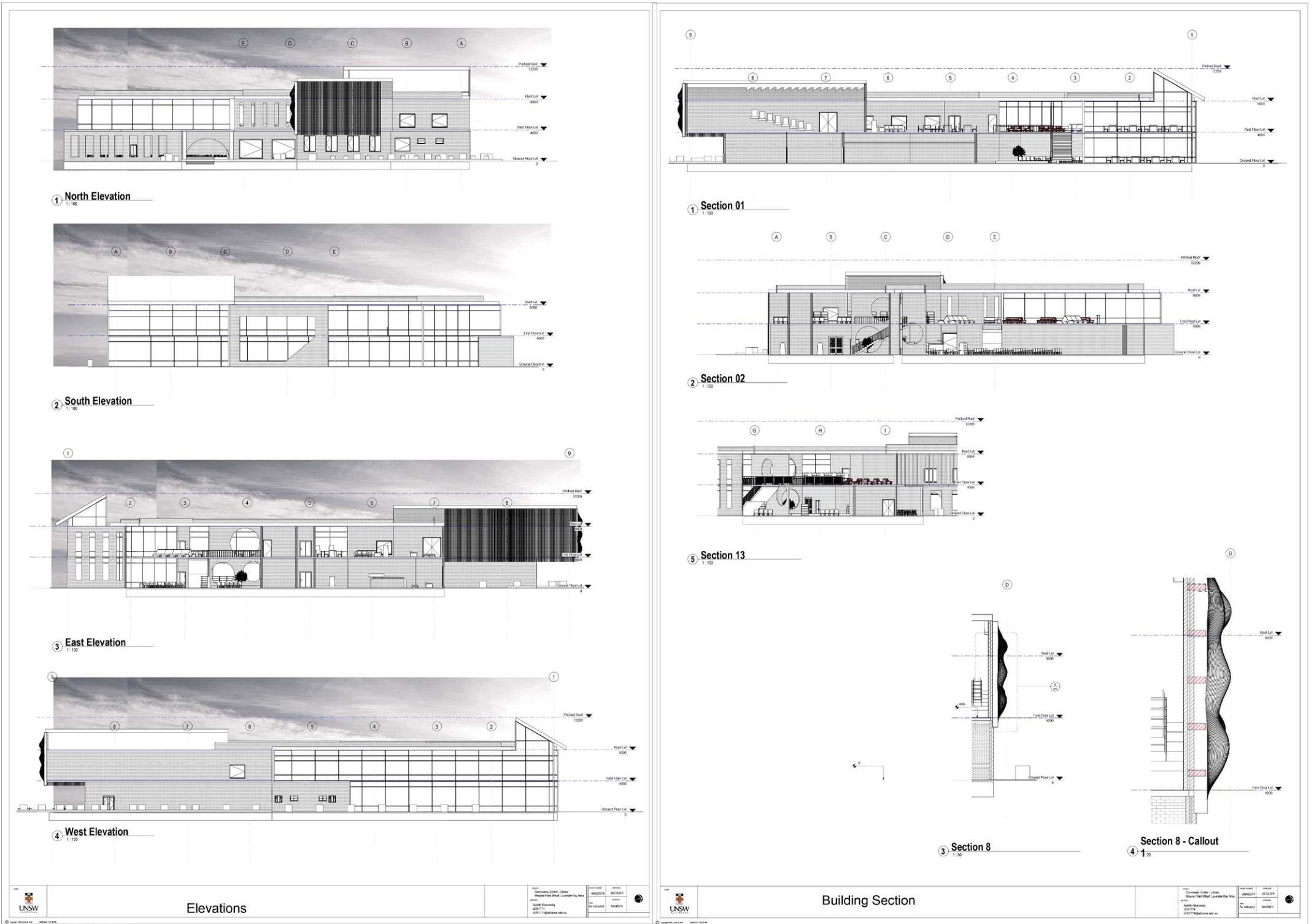
Fig.14 Floor plans for Community centre
Fig.15 Site Plan
Knowledgecentrehasactivitiesthathasbeen spread out into multiple levels, such a digital libray, central courtyard reading space, kids reading and play section, casual reading space, formal reading space, libary section, auditorium capacity of 150 people, along with a terrace reading space. The reading and library section in above floor is double height providing the space with mezzanine floor setting the space for informal terrace reading area overlooking the harbour and opera house. The auditorium for formal celebrations related to community centre. The central courtyard informal reading space along with kids area, helps the parents or care-takers to read books or newspaper in comfortable setting overlooking therir kids.


9
Fig.16 Section through Learning centre - Reading space, Courtyard space, Casual reading space, kids play and reading area
Fig.17 Section through Learning centre - Central reading space and book section along the recepetion admin and auditorium
Fig.18 Floor plans for Community centre


10
Fig.19 Sectional detail of Facade
Fig.20 View towards public plaza
Fig.22 View towards public plaza
Fig.24 View towards public plaza
Fig.21 View of Entrance to Learning Centre
Fig.23 View of Entrance to Learning Centre
n vdmsdnnvbhnc mncx
Fig.25 View of Entrance to Learning Centre
vbhdsvhbdshvbdssm
Design Brief
Parramatta Art Studio is a mixed development with an art gallery, exhibition space, along with studio apartment for the artists. Parramatta art studio’s plan to transform Parramatta into a second CBD as the ‘next great city’ have lately attracted significant media coverage and interest. The studio project, Parrmatta Artist Studio, calls for the design of a contemporary art space, a performance space, a cafe and retail, extensive public car parking and the reconfiguration of the Director of PAS, Sophia Kouyoumdjian says, “This will be a central for idea. It is where ideas are generated, refined, made concrete, put in place and exhibited. It is to make speculations and cross connections. It needs to have facilities for all media to support the generation and sharing of those ideas.” The site, Justice Precent Car Park (10 Hunter Street Parramatta) and immediate surrounds, being located in this dense urban environment, is imporant as a catalyst for the revitalisation of the CBD.
Design Concept
The site is located in the tight urban fabric of Parramatta area, surrounded with health and wellness buildings. So, it is very important for this space to act as a breathing space for all the activities around it.
The main design concept was to create an In-between spaces as a part of this Art Studio, where people can come and have a fresh air of new perspectives. The building material used is the precast concrete modules and they are arranged in a manner which creates lot of in between spaces which acts as terraces and spill out spaces for the activities and citizens too.

Parramatta Art Studio
11
The in-between spaces acts as a Community gathering spaces so that the built block needs to be open and an inviting space for public interaction. The built space has an interesting play of solids and voids. The focus was to design spaces in a way it overlooks to the surrounding creating an interactive manner.

This centre is focused on creating a platform for interaction and sharing new ideas amongst varied group of people. This in-between spaces is the key of bringing people together at a single place where the community has sense of belonging and togetherness. The spaces designed are very versatile in nature so many activities can be performed throughout the day instead of activity centric spaces which has limited number of activities happening. The site located is in the corner of Hunter street and O’Connel street which is the main road so it is important that this built block acts as an Identity of the place. The studio blocks and the apartments are facing in East-West direction to have good light and ventilation, aiming at a Sustainable approach for energy consumption.


12
O’Connel Street
Fig.26 Concept Develeopment Fig.27 Site Plan
Functional Organisation of the spaces
Heirarchical Division of spaces
Connection across the massing
Massing in the tight urban fabric
The ground floor level has Exhibition spaces, Cafeteria, Retail store and storage area which is connected with an In-between space in the middle. This in-between space is the meeting point for all and for everything as it is public in nature and main connection for the flow of movement. This in-between space is followed at all floor levels with different detailing and planning. So, each floor has a sense of ground at a higher level as well due to nature of spaces.


13
Fig.28 Ground Floor Plan
Fig.29 3D View of In-Between spaces
Fig.30 Ground Floor 3D Top view
From Fifth level, it is kind of private natured spaces as it has Artists studio and plaza, display areas for artists works and terrace gardens for recreational activities.
Sixth level also consists of artists studio and plaza, gathering spaces and activity areas. The blocks are shifted to get light and ventilation to all interior spaces without energy consumption.


14
The first floor plan consists of all public natured spaces like Auditorium, Exhibition gallery and
Section is showing the double heighted in-between spaces which allows the visual and physical connection between different activity spaces. Spaces between studios acts as an informal gathering spaces or some personal corner for an individual to think and create something.


15
Fig.35 Section AA
Fig.36 View from Hunter Street
Fig.37 View from O’Connel Street
Fig.38 Key Plan
Section shows the play of horizontal and vertical planes which gives the opportunity for interaction to happen as it creates an interesting built environment. The arches and circular openings are the elements used to add playfulness in the spaces with light and shadow of the sun.


16
Fig.39 Section BB
Fig.40 View of Terrace Spill out Zones
Fig.41 View of Entrance from O’Connel Street
Fig.42 Key Plan
The material used here is exposed brick, concrete and metal sections to give a very distinct language to the building. Overall building looks like an Art piece from outside; representing the functionality of the building and giving meaning to it. There has been an exploration in the scale of the spaces and the way the spaces are perceived is very different here.


17
Fig.43 Elevation from Hunter Street
Fig.45 View of Activity spaces
Fig.48 View of Studio Apartments showing the Visual connection
Fig.46 View of Exhibition Space
Fig.49 View of In-between spaces
Fig.47 View of Cafe
Fig.50 View of Auditorium space
Design Brief
Australian society and Sydney’s economy is in the midst of significant shifts – long term employment and the corporate ladder are being superseded by the gig economy and a workforce that must be agile, mobile, and self-directed. Within this reality, makerspaces are becoming increasingly common, providing spaces for small-scale entrepreneurs, hackers, and hobbyists to create “local solutions to local problems” (Gershenfeld, 2005). During the last decades, the standard approach of developed countries towards uncomfortable climatic conditions has been one of fighting and opposing nature rather than understanding and channelling its unlimited power to our benefit.
Design Concept
Architecture is the best tool to express ideas, emotions and expressions. It can be shown through the way the organization of spaces are done, the way the building materials are used, or the way the functional activities are thought to be performed.
Since, this institution is located in the industrial area and it is for the people to create products from scratch and work here. So, the best way to represent this was to use building materials in its pure form; i.e Brick and Concrete. And, with these material create a building which evokes the ethical and pious feeling. The construction methods have been explored to give a new meaning to the materials and the place too.

ThePippita Makerspace
Industrial Building
The Play of Solids
massing on site , led to a development of the final profile of the built-spaces.
The built spaces are designed in a manner that all the activities have visual connection with the main road i.e Parramatta Road and surrounding built spaces. Those spill out spaces acts as a breather between the solids, giving an interesting play of masses and voids. These connections seemed to be important because it is a Public natured building which should be in touch with its context directly or indirectly. So that, it doesnt look like an alien building in the already strong context that is existing.

19
Fig.51 Concept Develeopment
Fig.52 Site Plan
Fig.53 Site Section
and Voids
Showing Site access and Context
Arranging Masses on the site with existing context
Play of Solids and Voids
Connection with the existing building Visual Connection across the built spaces
Proposed Building
Synnex Building
The design concept was developed with an idea of creating solids and voids in the horizontal and vertical masses, providing a breathing and interactive spaces. The floors are divided in a hierarchical order providing public spaces in the lower level, and workspaces in the upper levels giving the sense of privacy. The main corridor acts as a spine connecting various spaces and it acts as the main space for interaction.

20
Fig.54 Ground Floor Plan | Showing the connections and transitions between Exhibition Spaces, Auditorium and Workshop area
Fig.55 Section AA | Showing the vertical connections and transitions between different Floor levels having varied scale and proportion
particular section shows the connection happening due to staircase being one of the interactive element which engages people and gives a platform to many activities. The design idea was to provide a visual connections from the adjacent Parramatta road creating a sense of connectivity along the activity space, which enhances the public interaction allowing them to understand the activity of the building.

21
Fig.56 First Floor Plan | The corridor connects with the secondary entry to the buidling through a bridge from Pipitta Rail track and the solids are the workshop spaces while the voids are the terraces.
Fig.57 Section BB| This


22
Fig.58 First Floor Plan | The corridor connects with the secondary entry to the buidling through a bridge from Pipitta Rail track and the solids are the workshop spaces while the voids are the terraces.
Fig.59 View from Birnie Ave
Fig.60 View of spill out spaces
Fig.61 View of Maker space from spill out zones
The data from site synthesis helped me to understand the need for a Community workspace in this functional built spaces. From that, I generated a concept of “Connection” which would bring in multiple activities under one roof. This would enhance the user experience as with workspaces many recreational spaces are also given here like auditorium, library, exhibition spaces, gardens and parks.

The design revolved around the word “Connection” which led in creating a Visual connection between varied activities taking place in the institution. The spaces were designed in a manner that it can get extended to the spill out spaces whenever required as walls were made flexible in it. The central spine which is created here acts as the main corridor connecting all the spaces at one place; hence making it the most important junction of interaction and movement.
The site has 3 entry points; two from ground floor and one from Pipita rail trail at first floor. So, the users of the rail trail can directly come to this place during their breaks and relax in those spill out spaces at Level 1 and Level 2. This way, the institution is always filled with people and some activities always goes on around here. Hence, the institution is always Connected to the city in some manner.
23
View from Birnie Ave
View from Western Motorway
View of Sculpture Park
View of Entrance Lobby
View from Birnie Ave
View from Sculpture Park
View of Bridge connection from Pipita Rail trailView of Entrance Corridor
View of Auditorium Waiting Area
View of Waiting Lounge View of Entrance Lobby View of Co-working space
Design Brief
Sustainable housing offers a great spectrum of opportunities to promote economic development, environmental stewardship, quality of life and social equality while mitigating the precarious convergence of the problems related to population growth, urbanistation, slums, poverty, climate change, lack of access to sustainable energy and ecconomy uncertanity.
Relationship between Housing and Environment
1. House building and operation require various environmental resources, such as building materials, water, energy and land.
2. Residential activities in human settlements have direct ecological impacts on local areas in terms of air and water pollution and damage natural eco-ystem.
3. Homes and their residents are also themselves exposed to varied environmental hazardsm which may emerge due to human activities, due to natural factors.
Design Concept
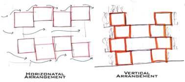
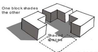
Designing a residential township in hot and dry region is a challenging task, as a residence should be a comfortable space for a user to carry on with his day to day task and living, it should provide a livable condition and ensure a habitable living space. To ensure a comfortable breathing space and provide a natural ventilation that would enable the units to receive convenient flow of air, the blocks are arranged according to wind direction, also the blocks are provided with ample amount of open spaces which would enhance the air flow within the blocks and also in-to individual units. The use of materials also being a key element is such region plays a vital role in maintaining the temperature of the interiors, the use of mud blocks and also clay bricks will help to maintain the temperature interiors as they would not heat the space unlike cement blocks. Benefits of Sustainable Housing -

1. Improved life quality and environment.
2. Improved efficiency and savings on the use of energy, water and other resources.
3. Better conditions for human development.
4. Durability and low maintenance of the built spaces.
5. Contribution towards climate adaption.
Housing Township
24


25
Fig.62 Master Plan showing EWS, LIG, MIG, HIG Housing, Markets, School, Hospital, CLubhouse, Commercial Centre and Industrial Area of a Housing Township
Fig.63 Master Plan showing EWS, LIG, MIG, HIG Housing, Markets, School, Hospital, CLubhouse, Commercial Centre and Industrial Area of a Housing Township
Arranging Blocks next to each other & giving green area in front
Deriving the plan forms and layout for the Mass Housing area
Play of Mass and Voids for the Mass Housing area
Deriving Horizontal and Vertical organisation Play of Light & Shade in the courtyard Conceptual Plan and Section of the Housing units3D Conceptual View of the Design Creating Micro-climate around the built blocks by inducing courtyards in the layout
To give good ventilation and sunlight, green areas are given between two blocks giving privacy to each houses.
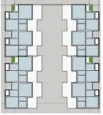
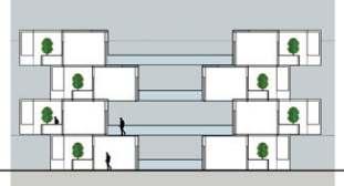
The 47sqm unit is a single bedroom unit for EWS category, which has been clustered to form a layout of 8 units per floor, providing a spill out space for congregation at all levels, while shifting the interaction space in alteranatove floors providing a double height interaction common space, overlooking the alternative space providing a visual connections and interaction of people.


26
Fig.64 EWS Unit and Cluster Details
EWS Housing Design was designed in a way it would enhance the interactive spaces within the community building, and create a sense of togetherness. The interconnecting courtyards enables one to visually connect with other residents visually.


27
Fig.65 EWS Cluster Section
Fig.66 EWS Cluster Sectional View
Fig.67 EWS 3D Courtyard view
LIG Housing units were designed with the intention of providing a central courtyard overlooking the housing units, making them a central space for congregation. The straight flight of stairs connecting multiple levels has a key element of interaction spaces, as one might find the stairs as a element of ascending or descending floors, while here they also behaves as space for interaction with the person ascending or descending from the opposite direction, which will enable the person to have an interaction during his flight of steps. The central courtyard space provides a large space for community activities.


view Cluster formation among the units create a large rectangular atrium which provides a void in-between the built space. This void enhances the user experience of interaction and improvise the activity programs Performed in the atrium provides a place for interaction which can cater for public gatherings and activities.

28
Fig.68 LIG Housing Unit and Cluster Details
Fig.69 LIG Housing Cluster Section
Fig.70 LIG Housing Cluster 3D


29
Fig.71 MIG Housing Unit and CLuster Details
Fig.72 MIG Housing Cluster 3D view
The semi-independent housing units with a private parking space, is a cluster of 4 units, making them a small cluster arrangement providing a common spill-out space at the rear of the built-space, providing the sense of privacy.
The individual 3 bedroom courtyard unit provides a comfortable environment with the use of exposed brick work, a private spill out space and deck seating in the ground level is a place of interaction with family , also the use of material plays a vital role, as the site context is in hot and dry climate, the use of brick work, water-body and landscape helps to create a micro-climate making the interiors a comfortable living condition.


30
Fig.73 HIG Housing Unit Details
Fig.74 HIG Housing Unit Details
Institution building for primary and higher primary education, catering to the residents of the township also from nearby places. The building profile is based on orientation and the massing of complete master plan as a whole. The triangular profile provides a central common space, which caters to school activities, and classrooms aligned with a break after 3 rooms for natural lighting into the corridor, makes the space more active with a break from the monotonous blocks and provides a space for kids interactions. The material of exposed brick work and concrete provides the vernacular style for the building.


31
Fig.75 School Block Floor Plans
Fig.76 School Block Sections
Fig.77 School Block Exploded View
Design Brief
Oasis a mixed use development design proposal at Chippendale, a project to learn BIM co-ordination, to understand working drawings and team management. Working with team members to combine individual works and binding them together with a central connection core that connects the built spaces together. A high-rise building, a library and a community center binding them with a bridge that connects all the buildings in different levels and making them feel connected.

Design Concept
Work, Play and Socialize
Oasis is a mixed used Development comprised of a total of 5000m2 with 2000m2 of community library, 1000sqm community center and 2000m2 of office tower. Located in the heart of Sydney in Chippendale at the corner of Daniel street and Moorgate street with access to all public transportation including public light rail, buses and 5 minutes walk to Central station, the masterpiece provided convenience and yet a social hub for the local neighborhood. The community center serving the heart of Chippendale community is an advanced facility continues towards low carbon footprint and highly performing building leads towards sustainability. While the 11 storey office tower aims to achieve green recognitions with zero carbon initiatives by use of recycled brick, building orientation with use of north facing operable aluminum fins and flexible interior planning. The community library center for learning, also community landscape that would help one to enhance the knowledge along with community gatherings, providing a sense of neighborhood livability. The unbuilt space provides an informal space for recreation and gathering which enables the activity of the place. The design concept of the Oasis is a response to the existing site context in an urban environment.