
AUGIWORLD
Managing Your Time, Workflow and Data
Boundary Pushing Performance
Push the boundaries of design with the Dell Pro Max T2 Tower. Engineered for architects, engineers, and creators who demand more. Powered by professional-grade NVIDIA RTX PRO™ GPUs, it delivers ultra-fast rendering, seamless multitasking, and unmatched reliability.


Dell Pro Max T2 Tower


in the Cloud for Revit and
A Deep Dive into ARES
Letter from the Editor AUGIWORLD

Here we are in August already. This month’s subject is Management, something I deal with daily. Also, our fearless leader, Eric DeLeon, hosts CAD Manager School (Skool). This is a forum that engages other managers, and we bounce ideas off each other. You can sign up and start engaging at https://www.skool.com/cad-manager-school. Eric is good about starting off the conversations.
It’s important to note that there are several styles of management. Depending on your manager, or if you are a manager yourself, you can be deemed to fit in a certain category based on your management skills and persona. Some of those styles include:
Autocratic – manager is placed at the top in a team. They control everything without obtaining input from other team members.
Democratic – this is the total opposite of autocratic. The team is at the forefront of decision making and the manager looks to the team for input.
Laissez-faire – this is where the manager lets the team members work for themselves and make their own decisions. A complete “hands off” approach.
Bureaucratic – this style relies on the rules, policies and standard operations. The team is evaluated according to goals, and it is measured and reported as such.
Servant Leadership – putting employees first, ahead of the needs of all other management or leadership.
Coaching – focuses on the employee’s professional development. Lots of training and support to help with employee skills and strengths.
Charismatic – this style solely relies on the personality of the manager to inspire and motivate employees.
Transactional – rewarding employees for their achievements and setting clear expectations.
Transformational – focuses on the motivation of the employees to “think outside the box”, to “raise the bar”.
Situational – this style is simply a mix of all the above…adaptation. What is your style? Is it effective? If not, maybe you should try one of the above methods and apply it to see if anything changes. My style is the last one, situational. I apply what needs to be done, in a manner that it needs to be done, in the situation that is at hand at that moment. Enjoy our articles this month from our awesome authors!
www.augi.com
Editors
Editor-in-Chief
Todd Rogers - todd.rogers@augi.com
Copy Editor
Miranda Anderson - miranda.anderson@augi.com
Layout Editor
Tim Varnau - tim.varnau@augi.com
Content Managers
3ds Max - Brian Chapman
AutoCAD - KaDe King, Chris Lindner
AutoCAD Architecture - Melinda Heavrin
BIM/CIM - Stephen Walz
BricsCAD - Craig Swearingen
Civil 3D - Shawn Herring
Electrical - Mark Behrens
Manufacturing - Kristina Youngblut
Revit Architecture - Jonathan Massaro
Revit MEP - Jason Peckovitch
Tech Manager - Mark Kiker
Inside Track - Rina Sahay
Advertising / Reprint Sales
Nancy Tanner - sales@augi.com
AUGI Executive Team
President
Eric DeLeon
Vice-President
Frank Mayfield
Treasurer
Todd Rogers
Secretary
Kristina Youngblut
AUGI Board of Directors
Eric DeLeon
Chris Lindner
Frank Mayfield
Todd Rogers
Shelby Smith
Scott Wilcox
Kristina Youngblut
AUGI Advisory Board of Directors
Gil Cordle
Jason Peckovitch
Rina Sahay
Jeff Thomas III
Publication Information
AUGIWORLD magazine is a benefit of specific AUGI membership plans. Direct magazine subscriptions are not available. Please visit www.augi.com/account/register to join or upgrade your membership to receive AUGIWORLD magazine in print. To manage your AUGI membership and address, please visit www.augi. com/account. For all other magazine inquires please contact augiworld@augi.com
Published by:
AUGIWORLD is published by AUGI, Inc. AUGI makes no warranty for the use of its products and assumes no responsibility for any errors which may appear in this publication nor does it make a commitment to update the information contained herein.
AUGIWORLD is Copyright ©2025 AUGI. No information in this magazine may be reproduced without expressed written permission from AUGI.
All registered trademarks and trademarks included in this magazine are held by their respective companies. Every attempt was made to include all trademarks and registered trademarks where indicated by their companies.
AUGIWORLD (San Francisco, Calif.)
ISSN 2163-7547
Bright Ideas for a Bright Future

AUGIWORLD brings you the latest tips & tricks, tutorials, and other technical information to keep you on the leading edge of a bright future.

Time and DWG Management with BricsCAD
Management. I am not sure about you, but when I hear that word, I think of about 414 different perspectives and topics within a matter of milliseconds. While none of us have the bandwidth to dive into the complexities of each of those for this article, we can discuss how BricsCAD® has the tools to help you manage your time, your drawings, and your bottom line—streamlining workflows, cutting software costs, and ultimately keeping everyone happy, users and especially upper management.
USING AI / MACHINE LEARNING
Outside of BricsCAD, I utilize AI tools every day, allowing me to get more accomplished in less time, so why wouldn’t I apply that same philosophy when I am using CAD? I am willing to guess you already use some AI/Machine Learning tools too, whether you know it or not. Using AI in CAD software presents the opportunity to speed up the design process by enhancing efficiency, accuracy, and overall quality of designs. AI tools automate tedious tasks and optimize designs, and CAD programs like BricsCAD use AI/Machine Learning to streamline the design process, giving you more time to focus on delivering high-quality designs.
BricsCAD tools like Blockify, CopyGuided/ MoveGuided, and the Quad are just a few of the AI / Machine Learning tools within BricsCAD. Let’s take a quick look at each feature and how they can help you manage time within and contents of your DWG.
BRICSCAD’S BLOCKIFY
Have you ever received/opened a DWG, and all of the symbols and/or entities have been exploded? What a mess, and how much time would it take to redo it all?
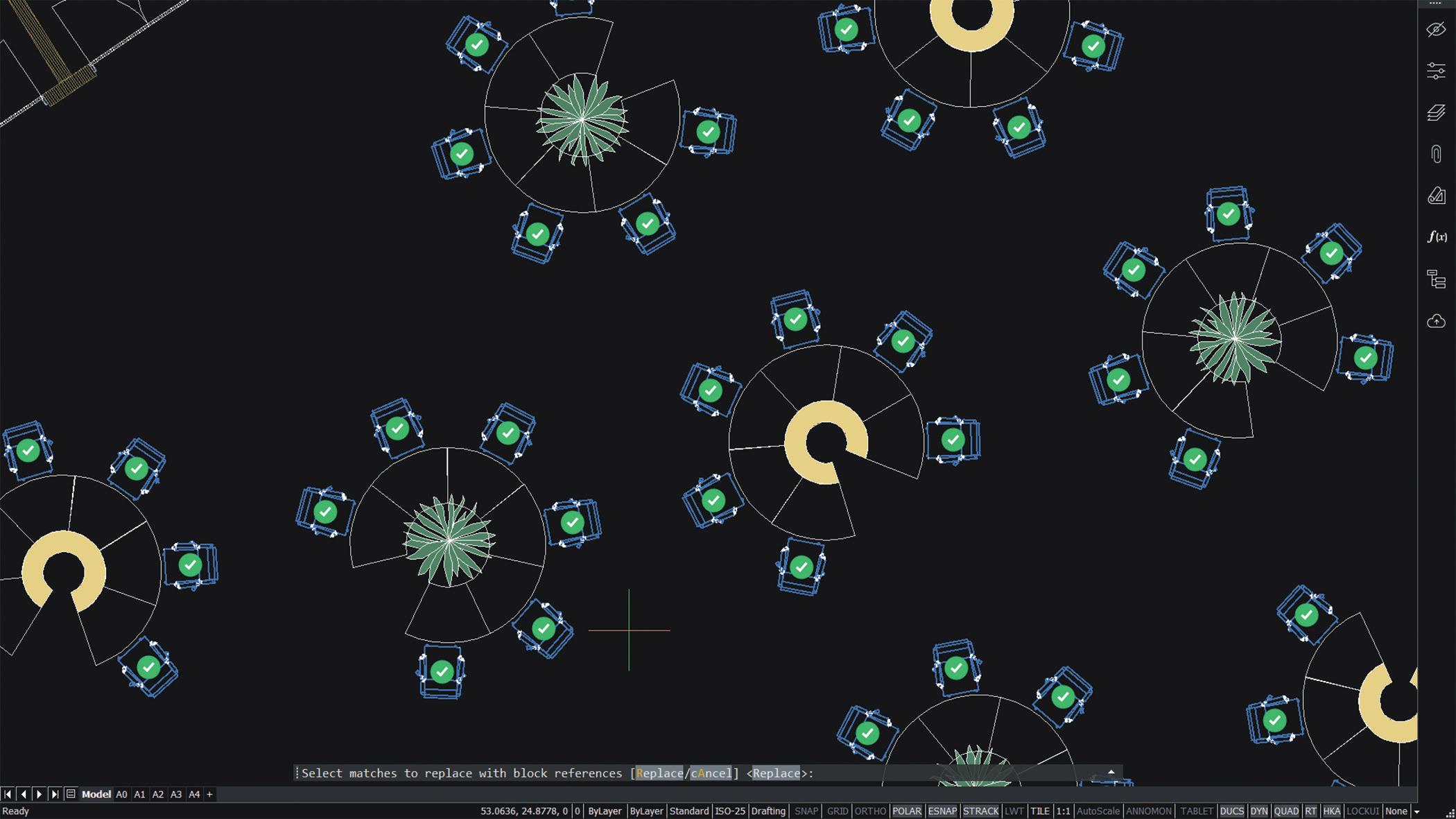
BLOCKIFY, introduced by BricsCAD years ago for the V19 release, converts repeated geometry into blocks. Blockify automatically creates a block definition and flags all matching sets of entities within your design, giving you the option to replace individual instances or replace all automatically. BricsCAD can either search the current drawing library, or the user can choose a selection manually to use as a reference. It really is that easy. (See Fig. 1)
Blockify removes the tedious and time-consuming tasks down to a few clicks, ensuring the drawings are easier to manage, seriously saving hundreds of manhours a year. You can choose to run Blockify independently, or it can also be added as a part
of another feature you can find only in BricsCAD, Drawing Health (DWGHEALTH), allowing you to reduce drawing size, remove unused styles, entities, and layers, purge those pesky Reg. Apps., and improve the overall drawing quality, all in just a few clicks. (See Fig. 2) Not only will the DWG files function better when working in them, but the initial opening of the DWG file will be much faster than before. Read more about BricsCAD DWGHEALTH in the May 2025 publication of AUGIWORLD
BRICSCAD’S MOVEGUIDED/COPYGUIDED
MoveGuided is ideal for CAD users who spend a lot of time editing drawings, moving entities around, and then fixing all the tiny errors.
For example, after reviewing the design plans, let’s say you notice the door and window on the outside wall are not in the correct location and both need to be moved to another wall. Generally, you would pick the door and window entities, use the move command to move them to the correct location. Typically, we then have to trim and extend the area where the door and window came from and the area where we placed them. With MoveGuided, this does not have to be a long, boring process of trim and extend. (See Fig. 3)
If you use MOVEGUIDED to move the door and window from one wall to another wall of similar geometry, BricsCAD will automatically orient and snap the door and window to the new wall. At the same time, it will heal the wall at the location where the door and window used to be and create
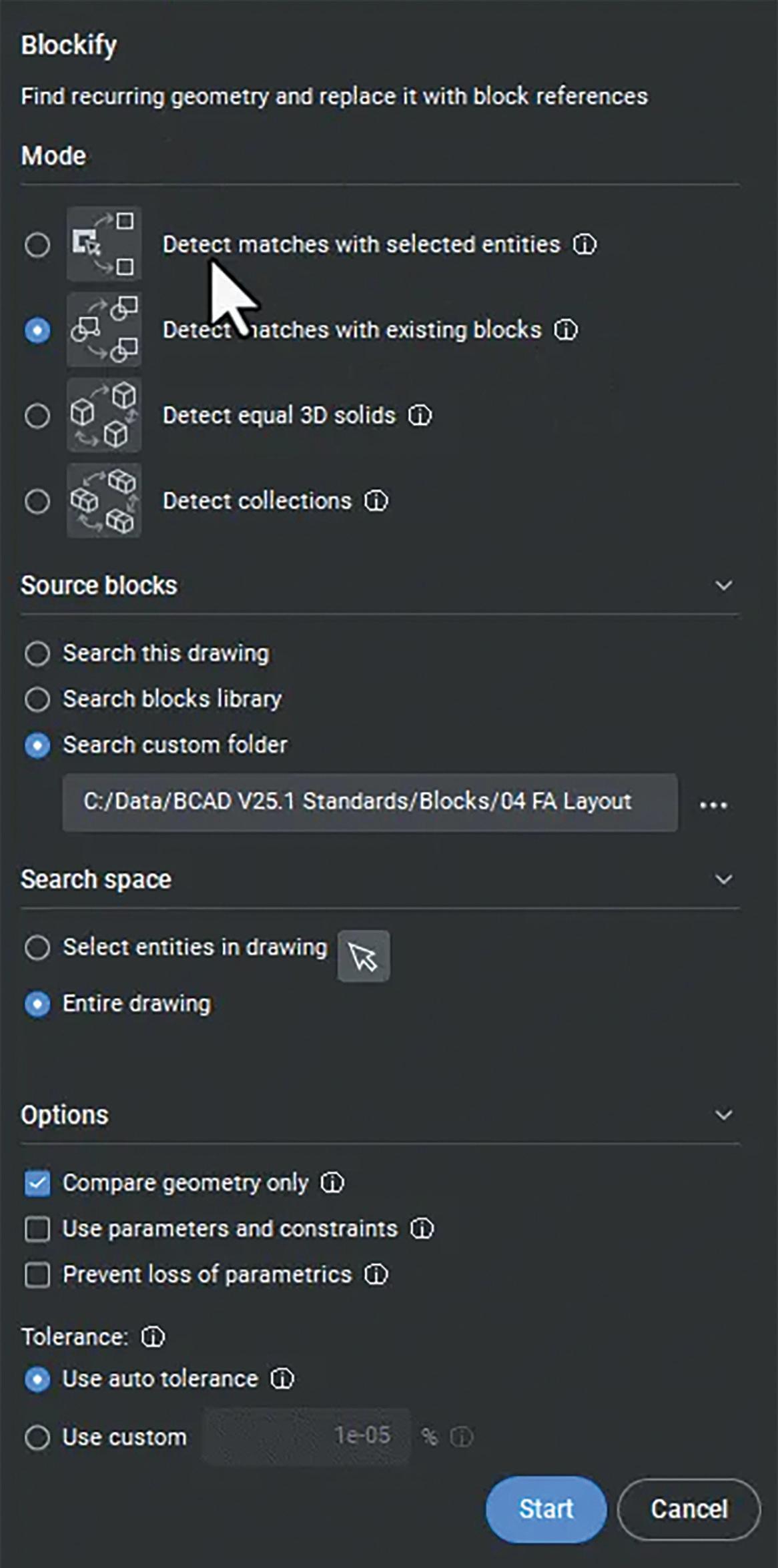
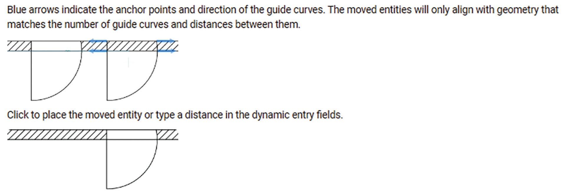
Figure 2
a door and window at the new location. Any lines or hatches will be healed in either location will be healed/joined.
So, what is CopyGuided? CopyGuided is similar to MoveGuided in that it will copy those entities to a new location, recognizing the reference lines/curves to make a perfect fit each time. How smooth is that? Speaking of smooth, look who just walked in? It’s the BricsCAD Quad!
THE BRICSCAD QUAD
Speed up your work by using the BricsCAD Quad Cursor Menu as an alternative to the command line, ribbons, or toolbars.
The BricsCAD QUAD is a context-sensitive graphic menu that offers a rich set of tools, which is dynamically displayed at the cursor. It uses entity
recognition and gives suggestions based on the most relevant and frequently used tools according to the active workspace and the entity you hover over. (See Fig. 4).
Adjust the BricsCAD Quad cursor to benefit the commands you use most frequently. With the Quad, it’s simple and easy to execute complex commands that normally require several clicks, options, and dialog boxes. This can significantly speed up your drafting and design work. No typing mistakes. Keeping your eyes up and on the screen.
MANAGE SOFTWARE COSTS AND REDUCE IT OVERHEAD
We just gave you some great tips about managing your time and managing your drawings within BricsCAD. What about managing your software costs and budgetary constraints?

BricsCAD
One of the primary financial benefits of BricsCAD lies in its flexible licensing options. Bricsys offers perpetual licenses, which allow users to make a one-time payment to use the software indefinitely. BricsCAD network licensing offers users the flexibility to break free from the limitations imposed by traditional licensing models. BricsCAD also offers a subscription licensing model, and regardless of the license type, all options are available at a fraction of the cost of other popular CAD software. (See Fig. 5)

As profit margins tighten and revenue targets become harder to hit, companies are under growing pressure to do more with less. Upper management has grabbed the magnifying glass. For large, global organizations, every line item is under scrutiny, including software costs. That’s why more global enterprises are turning to BricsCAD as a smarter, more affordable alternative to traditional CAD platforms. BricsCAD delivers the powerful design capabilities teams need at a fraction of the cost. By making a switch, companies can significantly reduce their software spend, freeing up budget for critical areas like staff retention, innovation, and operational growth.
CONCLUSION
In the end, BricsCAD empowers you to manage more than just drawings—it helps you manage your time, your resources, and your strategic goals. With intelligent tools like Blockify, MoveGuided/ CopyGuided, and the Quad, BricsCAD brings AIdriven efficiency to your fingertips, transforming the way you work. And when it comes to cost, BricsCAD proves that powerful CAD doesn’t have to come with a premium price tag.
In a time where every second and every dollar counts, BricsCAD isn’t just a tool—it’s a smarter way to design, manage, and succeed.
MORE ABOUT BRICSCAD
Bricsys BricsCAD is professional CAD software without compromise. Accelerate your time to deliverable without compromise on performance, cost, licensing flexibility, and data security. Not ready to buy? Download the free, 30-day trial of BricsCAD at Bricsys.com. Would you like free lessons? We have that available with Bricsys Learning. Ready to migrate to BricsCAD? Download the Migration Guide. The latest version of BricsCAD® improves the tools and features users love, as well as new functionality and UI that supercharge productivity. Follow us today on LinkedIn and YouTube.
MORE ABOUT BRICSYS
Bricsys, part of Hexagon®, is the global technology company that creates the BricsCAD® family of computer aided design (CAD) products and the Bricsys 24/7 project collaboration platform. We are relentlessly committed to the success of our customers by offering cost-effective, missioncritical CAD software with industry-leading product support. Learn more at www.Bricsys.com.

Mr. Craig Swearingen is a Global Implementation Specialist and Consultant at Bricsys. Currently, Craig provides migration and implementation guidance, management strategies, and technical assistance to companies which need an alternative, compatible CAD solution. Craig spent 19 years in the civil engineering world as a technician, Civil 3D & CAD power user, becoming a support-intensive CAD/ IT manager in high-volume production environments. Craig is a longtime AUGI member (2009), a Certified Autodesk® AutoCAD® Professional, and he enjoys networking with other CAD users on social media.
Figure 5

AUGI Members Reach Higher with Expanded Benefits
AUGI is introducing three new Membership levels that will bring you more benefits than ever before. Each level will bring you more content and expertise to share with fellow members, plus provide an expanded, more interactive website, publication access, and much more!
Basic members have access to:
• Forums
• HotNews (last 12 months)
• AUGIWORLD (last 12 months)
DUES: Free
Student members have access to:
• Forums
• HotNews (last 24 months)
• AUGIWORLD (last 24 months)
• AUGI Educational Offerings
DUES: $2/month or $20/year
Professional members have access to:
• Forums
• HotNews (full access)
• AUGIWORLD (full access and in print)
• AUGI Library
• ADN Standard Membership Offer
DUES: $5/month or $50/year
The Best Performance Review Ever –Part Two

Icontinue the topic of a performance review. Think of this as you sitting in the boss’s office and hearing feedback about your performance. Think of this as an evaluation of your work ethic, approach, output and impact on the firm and the staff. You deserve a pat on the back.
Last month we discussed what you do. Now we turn to who you are. You obviously have great technology skills. You have deep knowledge of the tech tools that you use and keep on learning more. And what you learn, you share with others. You know that knowledge is not something to hoard, it is to be distributed, and you sprinkle tips and tricks around the office all the time. You do not feel challenged or deflated when others may know more than you on some specific topic. You embrace their knowledge and collaborate to get things done. You expand your impact by bring them in to help others in that area where they shine.
Now I turn to who you are. It is your character, demeanor, perspectives and wisdom that bring so much value to the firm. I appreciate not only what you know, but who you are. The person you are when combined with the skills you have will open doors of opportunity to make a positive impact on the job, the design output and the firm.
You are winsome, friendly, work well with everyone and people are glad to have you around. When you start talking, people listen. They ask for your input and act on it, at all levels of staff and management. You encourage others and nudge them to step forward, do more and provide input. When you notice someone is quick to figure out solutions, you urge them to bring the fix to the team. When someone gives you an idea or answer, you praise them and give them the spotlight as the one who figured it out.
You are gentle in your correctives. When someone is veering off the correct path, you take them aside, in private if possible, and show them a better way of working. You do not joke about them in public. You treat them with kindness, even if it takes multiple times to get them back on track. When you drill down to find the root cause of a problem and find that it was “user error”, you do not place blame or point a finger. You soften the correcting message but still tell them how they can avoid the problem in the future.
You are kind to those that don’t grasp tech as quick as you do. When staffers take longer to understand how the tech tools are to be used, you slow down and explain it in differing ways. You anchor new concepts by comparing or contrasting to the old ways of doing things. You bridge the gap between what was done before and move people to a new and better way of doing things. You are patient with the “repeat offenders” and maintain a calm demeanor even though you may be very frustrated. You just explain it again, without demeaning inflections.
You are very resilient. When you face a setback, you quickly recover and adjust as needed. You know that the job can sometimes be challenging, monotonous, boring, defeating or seem unrewarding. But you don’t let it get you down. You just define another plan of attack and put one foot in front of the other and keep going. You know the good comes along with the bad. There are a lot of rewarding times when tech makes leaps forward and you get new tech that clears away the old annoyances and workarounds. And you recall those times and know that something good might be just around to corner. It keeps you going when times are tough.
When you say you will do something, you do it. When you give your word, people take it to the bank. You are trustworthy. You are aware that others are depending on you for solutions and you deliver. When you promise to do something, you follow through. You are wise enough to not make a promise that cannot be kept. When deadlines are set and you agree with them. You meet or beat the deadline.
It amazes me how many people you know in the tech community. You are connected to others outside the firm. You somehow squeeze in the time to attend events, meetings, lunches and
conferences where you link up with other teach leaders and vendors. You soak in the knowledge that others have and talk to other tech managers, picking their brains for info that might improve your production or fix your problems. You give as well as receive from others, sharing what you know and sometimes even speaking or presenting at events.
Your mindset if focused on customer service. Fixing other people problems is your sweet spot. Helping others know not only what to do, but why they need to do it is key to your success. You go above and beyond. You jump into the issues that pop up and get people back to work. You devise workarounds, patches, quick fixes and more to make the staffers more effective. You assist others with whatever is needed.
You love this stuff, and it shows. You display a vigor for tech work and have a positive expectation that tomorrow will be better, and tech will get you there. You jump in, twist the dials and test the limits. You keep your promises. You know a lot and you share a lot. You handle setbacks well and after a failure, you learn the lesson and adjust. You don’t let roadblocks stop your progress.
You have chosen a noble profession. One that is needed and appreciated. The need for technology managers and overseers is only going to grow and become more valued. You have worked hard to get where you are, and you continue to strive for excellence. You are good at what you do, and you bring talent, skills and perspectives that strengthen all of us. You are truly an exceptional Tech Manager.

Mark Kiker has more than 30 years of hands-on experience with technology. He is fully versed in every area of management from deployment planning, installation, and configuration to training and strategic planning. As an internationally known speaker and writer, he is a returning speaker at Autodesk University since 1996. Mark has served as Draftsman, Principal Designer, CAD/BIM Manager, IT Director, CTO and CIO. He can be reached at mark.kiker@augi. com and would love to hear your questions, comments and perspectives.

Engineering Approaches for the Calculation, Analysis, and Design of Slab-onGrade Systems
Slab-on-grade systems are widely utilized in residential, commercial, and industrial structures, forming one of the most common types of floor systems. Designing these slabs requires careful evaluation of how the concrete slab interacts with the supporting soil beneath it. Engineers must address several critical factors, including load-bearing capacity, crack control, shrinkage, temperature variations, and overall durability. Various engineering methods and computational tools are available to streamline the analysis and design of these systems.
1. Subgrade Assessment and Bearing Capacity Evaluation
The foundation of any slab-on-grade design begins with a thorough assessment of the subgrade—the soil or compacted base that supports the slab.
Common Methods:
Soil Investigation Reports: Geotechnical testing, including Standard Penetration Tests (SPT), Cone Penetration Tests (CPT), and laboratory analyses, help determine soil type, moisture content, strength characteristics, and compressibility.
California Bearing Ratio (CBR) Test: While commonly used for pavement design, this test also applies to lightly loaded slabs.
Plate Load Test: Provides direct measurements of the soil’s load response under simulated slab loads.
Design Considerations:
• Allowable soil bearing capacity
• Modulus of subgrade reaction (k-value)
• Expected settlement behavior.
2. Structural Analysis of the Slab
a) Analytical Methods
Westergaard’s Method: A classic approach used to evaluate stresses in thick slabs on elastic supports, accounting for slab thickness, soil stiffness, and applied loads.
PCA Method (Portland Cement Association): A practical adaptation of Westergaard’s theory, incorporating charts and formulas for typical slabon-grade applications.
Equivalent Frame Method: Models the slab as a system of interconnected beams to assess bending and shear forces, particularly useful for irregular slab geometries.

b) Finite Element Analysis (FEA)
2D/3D Modeling: Programs like SAP2000, SAFE, and ANSYS enable detailed simulation of the slab and subgrade interaction.
Nonlinear Soil-Structure Interaction: Advanced analysis accounts for nonlinear behavior of soil and time-dependent effects such as settlement and creep.
3.
Load Analysis
Slab-on-grade systems must be designed to withstand various loads, including:
Dead Loads: The self-weight of the concrete slab.
Live Loads: Dynamic loads such as vehicles, equipment, or storage.
Environmental Loads: Stresses from temperature changes, moisture fluctuations, and frost action.
Construction Loads: Temporary loads experienced during the casting and curing phases.
Load combinations are developed according to established codes such as ACI 318, ASCE 7, or Eurocode.
4.
Reinforcement Design
Recommended Practices:
ACI 360R Guidelines: Emphasize reinforcement for crack control rather than load-carrying capacity.
Temperature and Shrinkage Reinforcement: Calculated as a small percentage of the slab’s crosssectional area (typically 0.1%–0.2%).
Slab-On-Grade Systems
Mesh or Rebar Layout: Distributed evenly across the slab or concentrated in areas with higher stress concentrations, such as around openings or along slab edges.
Heavier industrial slabs may require additional elements like dowels or reinforced joints.
5. Crack Control and Joint Placement
Typical Methods:
Control Joints: Installed at calculated intervals to direct where cracks will form due to shrinkage and temperature effects.
Expansion Joints: Allow for slab movement caused by thermal expansion and contraction.
Construction Joints: Separate different slab pour phases during construction.
Joint spacing depends on factors like slab thickness, subgrade friction, and environmental conditions.
6. Slab Thickness Design
Slab thickness is selected using charts and formulas from standards such as PCA, ACI, or applicable local codes, considering:
Applied load types and magnitudes
Subgrade support (modulus of subgrade reaction)
Allowable stresses and safety margins
Standard slab thicknesses range from 4 inches for light residential loads to 12 inches or more for heavy industrial use.
7. Design and Analysis Software
Several specialized software tools assist engineers in performing accurate analysis and design:
SAFE: Comprehensive tool for slab design, including punching shear checks, reinforcement detailing, and soil-structure interaction.
RISAFoundation
STAAD Foundation Advanced Tekla Tedds
ETABS: Often used in conjunction with full building.
Construction.
Designing slab-on-grade systems is a multidisciplinary process that integrates geotechnical, structural, and construction
engineering principles. By applying analytical approaches, finite element modeling, and practical design standards such as ACI, PCA, and Eurocode, engineers can create efficient, durable, and safe slab systems. A thorough understanding of soil behavior, structural loading, reinforcement strategies, and joint detailing is essential to ensure long-term performance and reliability.

Ali Al-Azzawi, P.E., ENV SP Civil Engineer | Site Development & Structural Systems Specialist | Educator
Ali Al-Azzawi is a licensed civil engineer specializing in site development, civil and site design, and the integration of structural systems for a wide range of projects. His diverse project experience spans municipal, commercial, educational, and transit sectors, where he delivers comprehensive solutions in site layout, grading, earthwork, and infrastructure design. Ali is particularly skilled in erosion control strategies and advanced stormwater management, including both static and dynamic modeling approaches. In addition to his engineering practice, Ali is an active educator, teaching courses in Revit, Civil 3D, and construction management at Houston Community College. He brings real-world design and project management expertise into the classroom, preparing students for careers in the built environment.
Ali earned a Master of Science in Structural Engineering from the University of Houston, a Master of Science in Project Management from DeVry University, and a Bachelor of Science in Civil Engineering from Mustansriah University. He is a Licensed Professional Engineer in Texas and an Envision Sustainability Professional (ENV SP), demonstrating his dedication to delivering resilient, sustainable site and structural design solutions.

AutoCAD Architecture Managing Styles

The Style Manager is an AutoCAD Architecture utility that provides a central location where you can view and work with the styles that determine the appearance and function of objects in your drawings. You can manage many items in the Style Manager, including layer key styles, schedule data formats and definitions for cleanup groups, mask blocks, multi-view blocks and property sets. The Style Manager allows you to readily create or customize styles and share them with other users. In the Style Manager, you can perform the following tasks: Drag styles onto a palette to create tools
• Set up new drawings and templates by copying styles from other drawings or templates
• Access styles from open drawings and intranet sites
• Sort and view the styles in your drawings and templates by drawing or style type Preview an object with a selected style
• Create and edit styles
To open the Style Manager, begin by clicking the Manage tab, Style & Display panel and then Style Manager. You can also access the Style Manager by right-clicking any style-based object tool on a tool palette and clicking <object type> Styles. The Style Manager is split into two resizable panes and has a menu bar, a toolbar and a status bar (see Figure 1). When you open the Style Manager, all drawings and templates that are open in the current session are displayed in the tree view in the left pane. The left pane of the Style Manager displays the styles in all open drawings and templates in a hierarchical
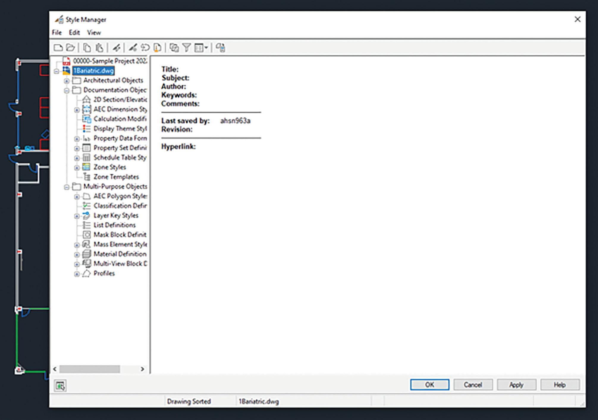
tree view that you can navigate by expanding and collapsing the different levels in the tree. By default, styles in the tree view are sorted by the drawing that contains them, but you can also sort them by style type. The tree view is always displayed in the left pane regardless of how you sort the styles. Figure 1.
Styles are organized into three categories: Architectural Objects, Documentation Objects and Multi-Purpose Objects. Within each category, styles are listed alphabetically. It is important to note that if drawings or templates are read-only, their readonly status is indicated by a lock on the folder next to the drawing in the tree view and also by a lock icon on the status bar.
The style information displayed in the right pane depends on what you select in the tree view in the left pane. For example, when the tree view is sorted by drawing and a style category is selected, the right pane lists the styles within the type. If an individual
style is selected, the right pane displays a series of tabs on which you can edit the properties of the style and preview how an object will display using that style. When the tree view is sorted by style, you can select a style type to view the distribution of the styles within that type across all drawings and templates that are open in the Style Manager.
The top of the Style Manager includes a menu bar and a toolbar for quick access to the menu commands. You can pause the mouse over a toolbar icon to display a tooltip describing the associated command. The status bar at the bottom of the Style Manager indicates how styles are sorted in the tree view (by drawing or by style), the name of the drawing and the currently selected style type and style.
WORKING WITH DRAWINGS AND TEMPLATES IN THE STYLE MANAGER
When you first open the Style Manager, any drawings or templates that are open in AutoCAD
Figure 1 – Style Manager
AutoCAD Architecture
Architecture are displayed in the tree view. You can also open other drawings or templates and create new drawings or templates within the Style Manager. When you create a new drawing or template in the Style Manager, or open an existing one, that drawing or template is open for use only within the Style Manager and not in your drawing session. You need to exit the Style Manager before you can open the drawing or template in the drawing session.
To determine whether a drawing or template is open in the software or only within the Style Manager, look at the icon next to the drawing or template in the tree view. The normal DWG symbol means that the drawing is open in the software and in the Style Manager. The DWG symbol along with an arrow in the bottom right corner means that the drawing is open only in the Style Manager. The DWG symbol with a lock in the bottom right
corner means that the drawing is locked. A drawing may be locked in the Style Manager for any of the following reasons:
• The drawing is read-only
• The drawing is referenced into a drawing that is currently open
• The drawing is open in another application
• The drawing was created in a previous version of the software
• The drawing file is locked on a network
To view a tooltip stating the reason for the lock, select the drawing in the tree view and pause the cursor over the lock icon on the Style Manager status bar. You can save your styles in a read-only source drawing and copy them to other drawings as necessary. Any drawings and templates that you create or open in the Style Manager are listed in the tree view every time you open the Style Manager until you close them from within the Style Manager.
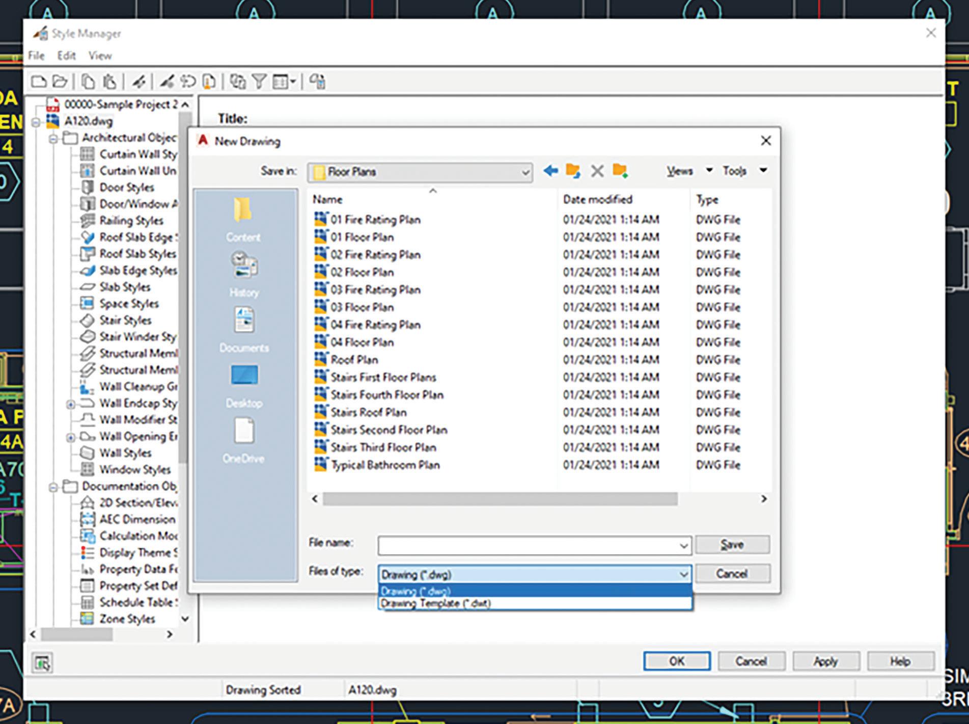
You can start a new drawing or template in the Style Manager. The new drawing or template does not contain any styles and is open for use in Style Manager only. It is not open in the AutoCAD Architecture session. You can open the new drawing or template in the software after you exit the Style Manager. Begin by clicking on the Manage tab, Style & Display panel, Style Manager. On the Style Manager menu bar, click File New Drawing. In the New Drawing dialog box, for File Name, enter the new drawing name (see Figure 2). For Files of Type, select Drawing (*.dwg) to create a drawing or select Drawing Template (*.dwt) to create a template and then click Save. Now click OK.
CREATING A STYLE IN THE STYLE MANAGER
If you want to create a new style or definition for a particular type of object, you can start with the default style properties for that object type or
AutoCAD Architecture
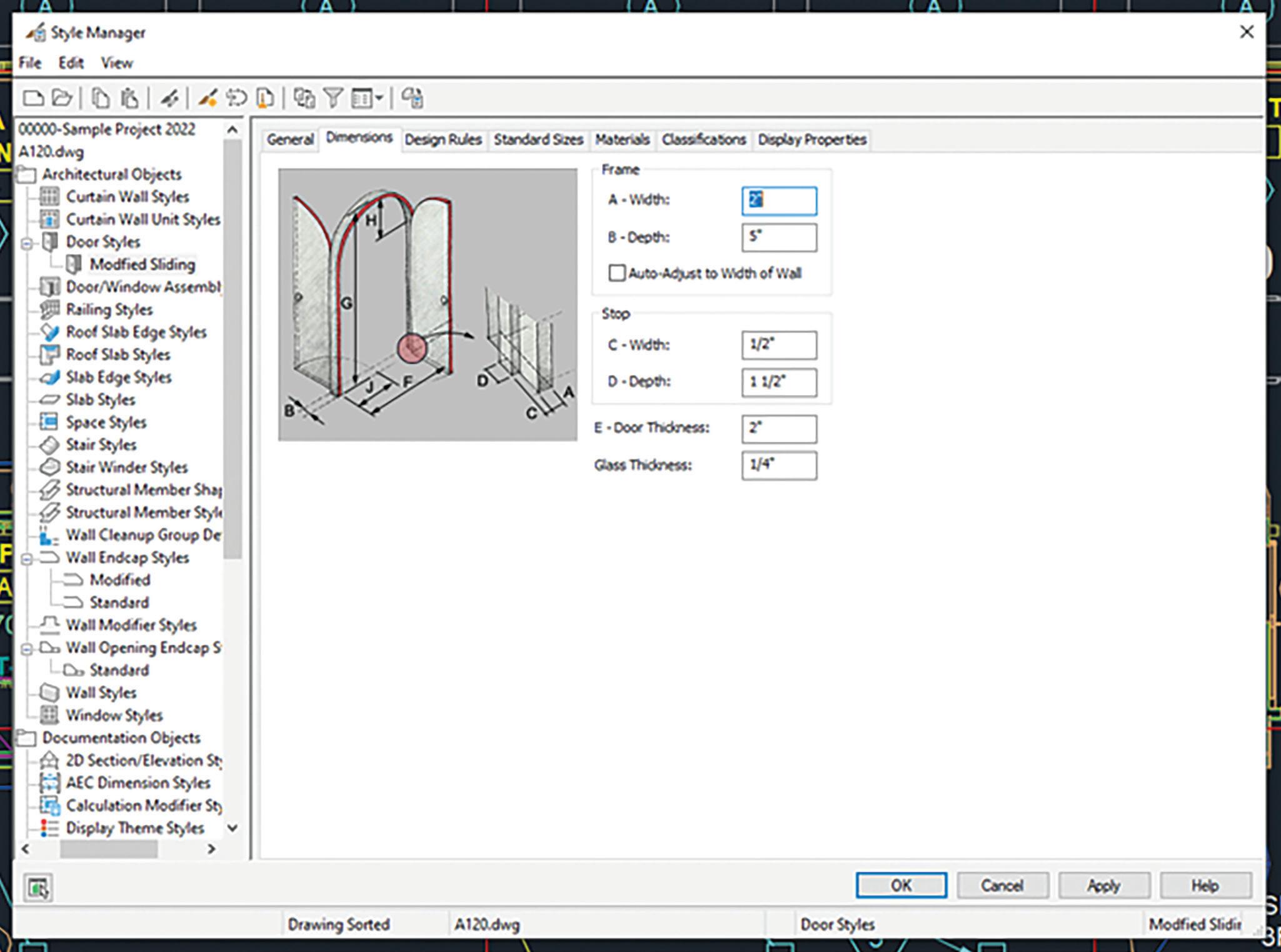
you can copy an existing style that has most of the properties you want. In either case, you then edit the style properties as needed to specify the desired object characteristics. Begin by clicking the Manage tab, Style & Display panel, Style Manager. The Style Manager displays with all open drawings listed in the tree view and the current drawing expanded. Now expand the object category (Architectural, Documentation or Multi-Purpose) and object type for which you want to create a style. If you want to create a style with default properties, then right-click the style type and click New. If you want to create a style from an existing style, then expand the style type, right-click the style you want to copy and click Copy. Right-click and click Paste. On the General tab, enter a name and description for the new style. Click on the other tabs as needed to view and edit the properties (see Figure 3). When you finish specifying the properties of the style, click OK. The new style will be listed if you open the
AutoCAD Architecture
Style Manager again while the drawing remains open, but it is not saved until you save the drawing. After you have created a style, you can drag it from the Style Manager onto a tool palette to create a tool.
SORTING STYLES IN THE STYLE MANAGER
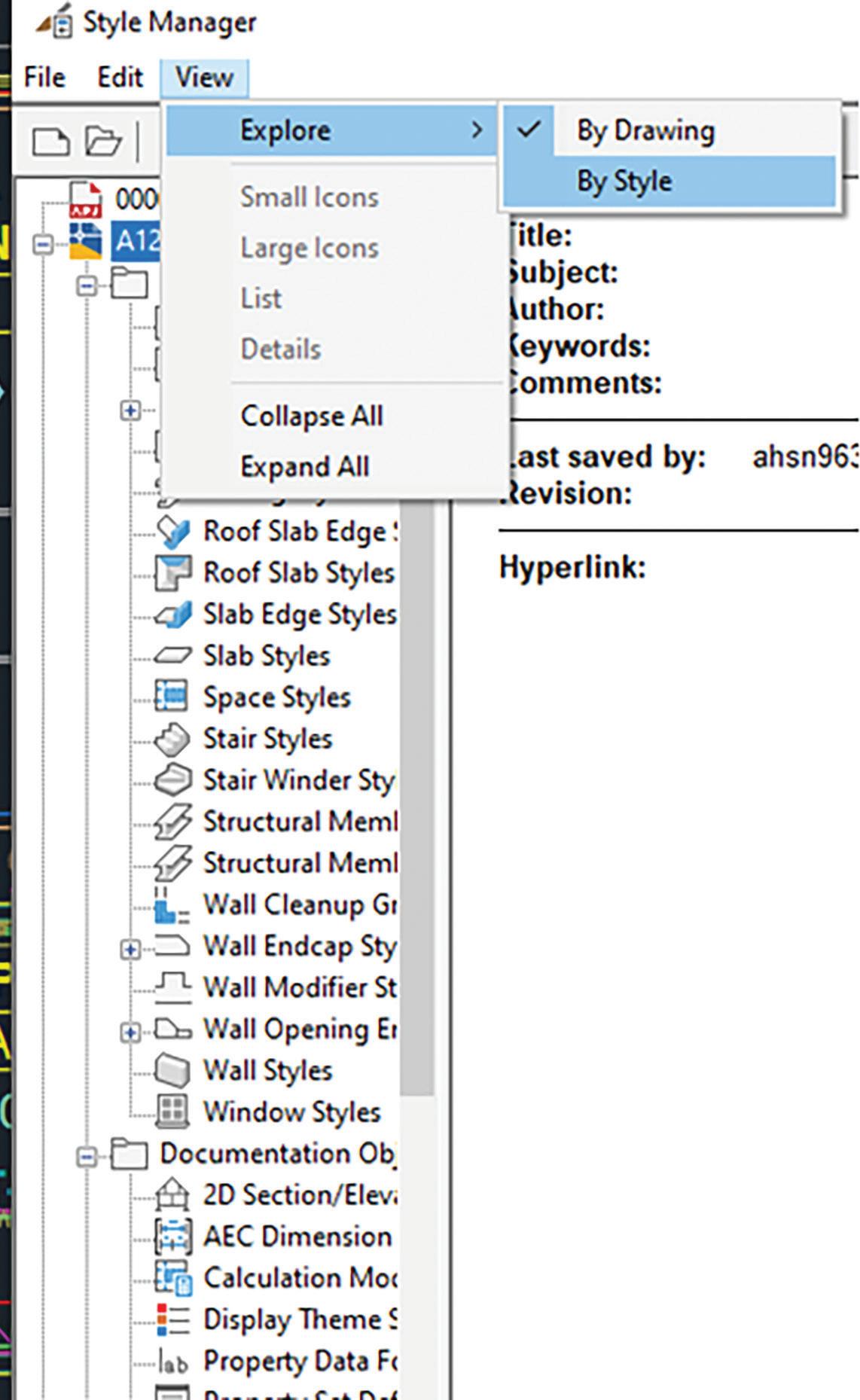
You can change the way styles are sorted in the Style Manager. By default, the names of open drawings and templates are displayed in the tree view in the left pane. When you expand a drawing in the tree view, the individual styles within the drawing are grouped into three categories: Architectural Objects, Documentation Objects and Multi-Purpose Objects. If you expand a category, the individual styles are listed alphabetically by style type. To see the styles available in each drawing for a particular style type such as door styles, you can sort by style. Styles are then grouped by category and organized by type and then by drawing. The status bar at the bottom of the Style Manager indicates whether the styles are sorted by drawing or by style type.
To switch how styles are sorted in the Style Manager, begin by clicking on the Manage tab, Style & Display panel, Style Manager. By default, styles are sorted by drawing. On the toolbar of the Style Manager, click the Toggle View symbol to sort styles by style type. Alternatively, on the menu bar of the Style Manager, click View menu, Explore, By Style (see Figure 4). If you want to view the styles available in a drawing, expand the category, a style type, and then the drawing. To restore the bydrawing sort order, click the Toggle View symbol again.
ADDING STANDARD STYLES FROM THE STYLE MANAGER
You can add standard styles to project drawings in the Style Manager. When standards drawings are specified in the project standards configuration, they are displayed in the Style Manager when you open a project drawing. Styles can be dragged from the project node to the project drawing node here. To do this, begin by opening the project drawing to which you want to add standard styles. Click the Manage tab, Style & Display panel, Style Manager. The standards drawings specified in the standards configuration are listed under the project node. Expand the node for the project standards drawing containing the style you want to add and expand
sub-nodes as necessary to locate the style. Now drag the style from the project standards drawing node to the project drawing node in the tree view. The standard style is copied to the project drawing node. Click OK.
It is important to note that for the synchronization of the standard style to work, the style needs to come from a standards drawing that has been selected as a standards drawing for this style type in the configuration setup. For example, if the standards drawing “Wall Styles.dwg” has been configured as the standard for wall styles and the standards drawing “Door Styles.dwg” has been configured as the standards drawing for door styles, you should not copy any wall styles from the “Door Styles.dwg” to the project drawing. Because that drawing has not been defined as the
Figure 4 – Style Sorting
standards drawing for wall styles, the copied styles will display as not standardized in the synchronization.
You can also drag styles from a project standards drawing into a drawing that is not part of the current project. If the drawing is not part of any project, no synchronization will happen to that style in the future. (See Figure 5) If the drawing is part of a different project, the style will display as not standardized in future synchronizations of that project unless that project references the same standards drawing from which the style was dragged.
CREATING A TOOL FROM THE STYLE MANAGER

You can create a tool from the Style Manager. To do this, begin by opening the tool palette where you want to create the new tool. Click Manage tab, Style & Display panel, Style Manager. Now select the style from which you want to create a tool. For example, if you want to create a wall tool with the Stud-3.625 GWB0.625 Each Side (1 Hour) style, expand Wall Styles and select the Stud-3.625 GWB-0.625 Each Side (1 Hour) style. Drag the style to the tool palette. A new tool with the selected style is inserted in the tool palette. Click OK to close the Style Manager. Define additional properties for the tool in the tool palette, if necessary.
DRAGGING A DRAWING INTO THE STYLE MANAGER
You can open a drawing or template in the Style Manager by dragging it from Microsoft Windows Explorer. The drawing or template will be open only within the Style Manager; that is, it will not be open in the AutoCAD Architecture session. If you wish,
you can open the drawing in the software after you exit the Style Manager. In the Style Manager, sort the styles by drawing. Start Microsoft Windows Explorer and select the drawing or template that you want to open in the Style Manager. Drag the drawing into the tree view in the Style Manager and click OK.

Melinda Heavrin is a CAD Coordinator & Facility Planner in Louisville, Kentucky. She has been using AutoCAD Architecture since release 2000. Melinda can be reached for comments and questions at melinda.heavrin@ nortonhealthcare.org.
Figure 5 – Synchronization
Time Management –
In Civil Engineering and in LIFE!

Time management is a core skill that can make or break your productivity, reduce stress, and help you hit your goals consistently. This is a process of planning and exercising conscious control over how much time to spend on specific activities — to maximize effectiveness, efficiency, and productivity.
Let’s talk about time management specifically for civil engineers, where juggling design work, field coordination, meetings, and deadlines are a daily reality.
WHY IS TIME MANAGEMENT SO IMPORTANT?
1. Reduces Stress – Knowing what you need to do (and when) helps you avoid last-minute scrambles. And with last-minute scrambles, that’s where mistakes and problems tend to creep in.
2. Improves Focus – You stop reacting to your day and start leading it. It may be best to just let the phone ring! If I had to stop my task every time someone called or texted, I’d never get anything done. Set aside “call back hour” or something so
you’re not constantly switching gears.
3. Creates Space for What Matters – Better time use = more freedom for family, growth, or rest.
4. Enhances Reputation – Meeting deadlines and being dependable builds trust. To be known as the “go to” person for top projects, questions or even internal trainings is job security in itself.
WHY CIVIL ENGINEERS STRUGGLE WITH TIME MANAGEMENT?
Civil engineers juggle many roles—design, project management, site visits, client communication, documentation, and regulatory compliance. Constantly switching contexts reduces focus and increases the risk of delays or errors. Every time you stop a task you tend to backtrack when you restart. It’s a very inefficient way of working.
Frequent changes from clients, architects, or other stakeholders can derail timelines. Managing and implementing revisions, especially late in the project—consumes valuable hours and breaks workflow momentum. An understanding of the dynamic models in Civil 3D can help eliminate major rework. We’ll explore some of that later in the article.

My #1-time killer?? Unproductive meetings!! I like to have a 30-minute max meeting time. If a meeting lasts longer than that, it typically means we aren’t communicating properly leading up to that meeting.
Implement a Weekly Review Process
Every Friday (or Monday AM), do a 20-minute check-in:
• What’s due next week?
• Any slowdowns from clients or fields?
• What do you need from others? What do others need from you?
Use this time to prioritize, delegate, or clarify scope creep.
Civil Engineering
Time Wasters to Eliminate
Time Waster Solution
Long, aimless meetings
Constant field interruptions
Manual data reports
Searching for old files
Ask for agendas & set time caps
Batch communication at set times
Use Civil 3D Project Explorer, QTO or others
Organize templates, folders & file naming conventions

Civil Engineering
Standardize & Automate Repetitive Tasks
If you’re using Civil 3D, Revit, or similar tools, spend time upfront creating:
• Templates (for alignments, profiles, and sheets)
• Label styles and surface settings
• Scripts/macros or Project Explorer reports for common deliverables
That prep saves hours on every project and eliminates rework.
Build “Design Sprints” into Your Workflow Group similar tasks (e.g., drainage layout, grading, or plan set cleanup) into focused sessions. Avoid switching between tasks (like emails and grading) every 10 minutes — it destroys your momentum.
Here are MY 5-time management killers when using Autodesk Civil 3D, especially in productionheavy environments.
1. Poor Template and Standards Setup
• Why it kills time: Inconsistent layers, styles, label settings, and object defaults mean users must adjust each item manually. Opening past projects to drag styles into new projects, instead
of simply adding them to your template, is a huge time suck.
• Examples: Labels don’t match project standards; styles must be constantly changed; alignments don’t default correctly, etc.
• Fix: Invest time in a well-developed Civil 3D template (DWT) with standardized styles, layers, and settings. Train on your template!! This is overlooked way too often. A good training on your template, and refresher training throughout the year, will help users really understand the styles and power of your Civil 3D template.
2. Lack of Understanding of Dynamic Model Behavior
• Why it kills time: Civil 3D is model-based and dynamic. When users don’t understand object dependencies (e.g., alignment > Profile > Corridor > Surface), they make changes in the wrong order or overwrite work.
• Examples: Editing a surface that’s tied to a corridor without realizing it will update everything. Manually adjusting the structure rim elevation and breaking the tie to the surface.
• Fix: Train users on Civil 3D’s object relationships and leverage data shortcuts (DREFs) effectively.

Civil Engineering
3. Inefficient Data Management and DREF Usage
• Why it kills time: Misuse or overuse of Data Shortcuts can cause broken references, bloated drawings, or rework when objects don’t sync properly.
• Examples: Teams work on different copies of the same alignment or surface; syncing causes confusion or duplication.
• Fix: Set clear folder structures and naming conventions for data shortcuts. Use Source drawings wisely. Ask yourself if you really need a DREF, or does an XREF suffice in this situation?
4. Large File Sizes and Drawing Bloat
• Why it kills time: Large drawings slow down Civil 3D performance, increasing load/save times and causing crashes or lag.
• Examples: Unpurged files, excessive xrefs, unused styles, or copying/pasting from other drawings.
• Fix: Regularly use -PURGE (Regapps), AUDIT, and CLEANUP. Use external references properly and avoid copying unknown content from other DWGs.
• Here’s a past article on file managementhttps://www.augi.com/articles/detail/civil-3d-filemanagement
5. Manual Drafting vs. Using Civil 3D Tools
• Why it kills time: Users sometimes revert to AutoCAD-style drafting (lines, text, blocks) instead of using Civil 3D’s dynamic tools. Especially annotation!
• Examples: Manually drafting profiles or labeling elevations instead of using profile views or
surface labels. Manually labeling a structure and not fully understanding structure labels.
• Fix: Train staff to use Civil 3D objects (alignments, feature lines, surfaces, labels) instead of dumb geometry and text. Can it replace 100% of manual drafting? Absolutely not! But when you go to annotate something, just ask yourself if there’s a style for that.
Time Management Techniques That Work for me
1. Daily and Weekly Planning
• Spend 10–15 minutes at the start/end of your day to plan. I begin and end each day with a quick task list that I physically write down, and yes, I waste a lot of paper. But how satisfying is it when you go to close out your day and you get to scratch items off that list!!
• Weekly overviews help spot upcoming bottlenecks.
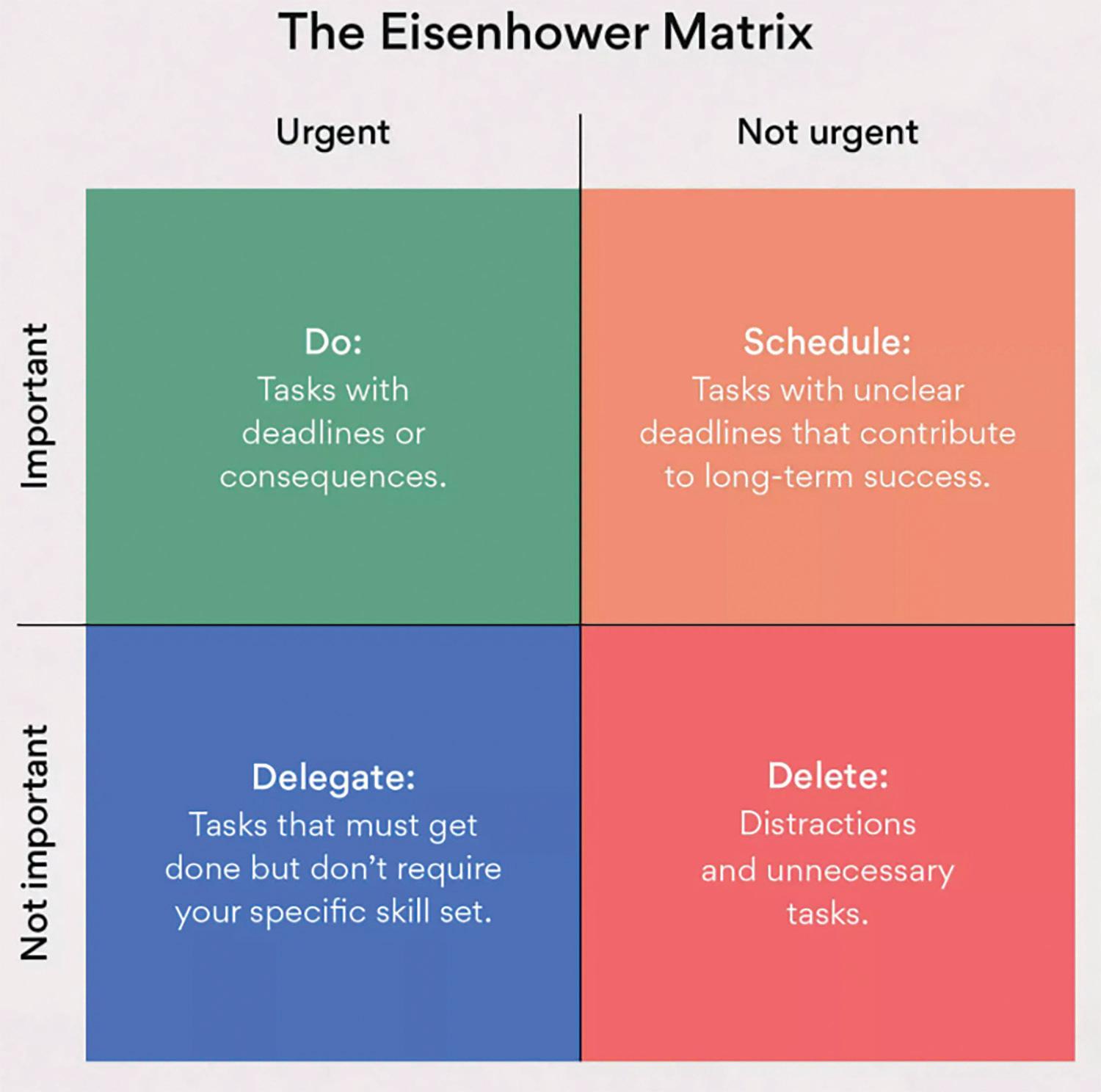
2. The Eisenhower Matrix
• Urgent vs. Important. However, a common pitfall here is determining what is also important or urgent to others, not just yourself. So, consider that sometimes getting to a task that may not be important to you, but important to someone else, will save you a lot of time and interruption from the other party!
• Helps you prioritize instead of just reacting.
3. The 2-Minute Rule
• If a task takes less than 2 minutes, do it immediately. Get it out of the way. I live by this daily. The first 15 minutes of each day I review my tasks, then the next 30 are dedicated to the little things. An email, 1 quick redline note, a response to a meeting request, or setting up meetings.
• Prevents minor tasks from snowballing. How often do you discuss for 30 minutes or more a 2-minute task? How many times has someone interrupted you waiting on you to complete a 2-minute task? How many phone calls do you get asking if you received an email, when you could have simply responded? Don’t let a 2-minute task snowball into an hour of time suck, just get it done!
4. Align Tasks with Your Energy Levels
• High-focus tasks during peak energy (usually mornings). My peak hours are usually 6am-8am, and 9pm-11pm. Midday I’m a bit sluggish and tend to get distracted. Thankfully over the past


couple years I’ve been in a place where if I feel my productivity slipping, I bounce for the day! Not literally jumping up and down, but I leave, I go to the gym, I coach softball, so that gives me an escape. I remove myself momentarily knowing I won’t be productive, and I replace those “lost hours” with higher productive hours.
• Low-focus tasks (emails, admin work) when energy dips. We all have tasks we dread and mine are boring admin related tasks. Timesheets, billings, contracts, HR issues, etc, etc. But they must get done! Most of them don’t take a lot of brain power, so I tend to focus on those either right before or after lunch when I’m distracted by having to choose what taco joint to eat at!
CONCLUSION
I know this wasn’t a pick and clicks type of article, but what good are the picks and clicks if you don’t manage your time wisely? I hope this helps or gives you some ideas on how to more efficiently run your days and weeks ahead!

Shawn has been a part of the design engineering community for roughly 20 years in all aspects of design, construction and software implementations. He has implemented and trained companies across the Country on Civil 3D and other infrastructure tools and their best practice workflows. Shawn can be reached for comments or questions at sherring@ prosoftnet.com.

Auto-drawings in the Cloud for Revit and IFC: A Deep Dive into ARES Kudo’s New Features
Generating 2D drawings in DWG from BIM projects is an essential step between design and build, but also a tedious and time-consuming one. With ARES Online Drawings Automation, ARES Kudo can handle this task for users — and offer customization options for large accounts and developers.
Something important must, by extension, be exciting! Well, we might have had that expectation when we were young, but as adults, we know better. We’re resigned to the fact that important chores are often repetitive, time-consuming, and downright tiresome. So, we fold the laundry and
floss our teeth and sweep the floors, over and over and over again. Tedious as they may be, we simply must put the time in to take care of these tasks … or do we?
Of course, the floors need cleaning — but that job doesn’t necessarily require human effort. A burgeoning fleet of robotic vacuum cleaners, whirring their way into more homes and hearts every day, has made that clear. And thanks to the new Online Drawings Automation service in ARES Kudo — Graebert’s DWG-native CAD solution that runs in an Internet browser — users can hand off some very important CAD chores as well.
ADDRESSING THE SHORTCOMINGS OF EXISTING AUTOMATION TECHNOLOGY
Before we dive deeper, let’s address the elephant in the room. Yes, if you’re using Revit or other BIM software, you can automatically generate 2D drawings from your BIM models and even export them to formats like DWG or PDF. However, the process still requires manual effort for adding dimensions and labels. Furthermore, many details present in the DWG files (such as construction details, furniture layouts, or elements related to water, electricity, IT networks, and even garden irrigation) are typically added by CAD users — they don’t originate from the BIM model itself.
Despite BIM software streamlining the initial drawing process, much of this work remains manual, and that burden falls on everyone’s shoulders: BIM users are responsible for creating the labels and dimensions, while CAD users manage the addition of extra layers of information. The real challenge, however, lies in keeping the DWG files synchronized with the evolving BIM model. Currently, this means re-exporting and
re-editing drawings repeatedly, leading to a neverending headache.
But what if there was a better way? Imagine if you could keep your DWG files and BIM models in perfect sync. What if you could generate DWG drawings directly from your Revit or IFC models, complete with automatic dimensions, automatic labels, automatic styling — and automatic updates? And what if this task could run on a server, scheduled daily or overnight, freeing up your computer from the load and running in the background, while preserving all the additional data added by CAD users?
This is the promise of Auto-drawings and the new ARES Online Drawings Automation, developed by Graebert.
GRAEBERT EXTENDS ITS BIM-TO-CAD AUTOMATION TO THE CLOUD
The unique integration of online CAD and automatic task execution in ARES Kudo enables users to not only access, create, and edit DWG files

ARES Kudo
from any Internet-connected device, but also to automate repetitive tasks involving those files. For many AEC professionals, the generation of DWGformat 2D BIM drawings — including floor plans, sections, and elevations — from BIM models is high on the list of such tasks.
Anyone who works at the intersection of BIM and CAD knows that these drawings are unquestionably important; they are how design is put into action on the building site. But these professionals also know firsthand that creating drawings from imported BIM files can drain hours from the day, if done manually. Thankfully, Graebert’s BIM Drawings Automation features replace hands-on effort with the click of a button — saving users time for other tasks (like the laundry).
access those capabilities on any device, anywhere they have an Internet connection.
THE ADVANTAGES OF TAKING DRAWINGS AUTOMATION ONLINE
Whether you use BIM Drawings Automation, the CAD Automation features, or both, you’ll soon find that the Auto-drawings technology in ARES Kudo offers significant advantages for your workflows. Have you ever put progress on hold while you waited for your software to complete a task?
Never again! Because ARES Kudo Automation leverages the power of ARES Commander running on a distant server, it executes its tasks in the background. It won’t interfere with your work, so you can continue as usual while your Automation jobs are processed. You can even log out of ARES

Visit the following website to see how ARES Kudo can automate the production of 2D DWG-format BIM drawings from imported Revit and IFC BIM projects. www.youtube.com/watch?v=m-khlT-goCU &list=PLStPIOsWm9vFjJdp1ulh2Aeqx3NfxR8tS&inde x=12&t=1s
Graebert first unveiled its BIM Drawings Automation features in ARES Commander, its desktop CAD application. Now, the Online Drawings Automation service in ARES Kudo enables users to
Kudo altogether; your automated tasks will proceed as planned, whether you’re there or not.
You can also choose to have your jobs run in the future: after you hear back from the client next Wednesday, perhaps; or after work is done for the night, you’ll have the most up-to-date files for that discussion with your boss in the morning. Thanks to ARES Kudo’s scheduling capabilities, you can simply choose the time you want your job to enter the processing queue. (Note that actual job execution
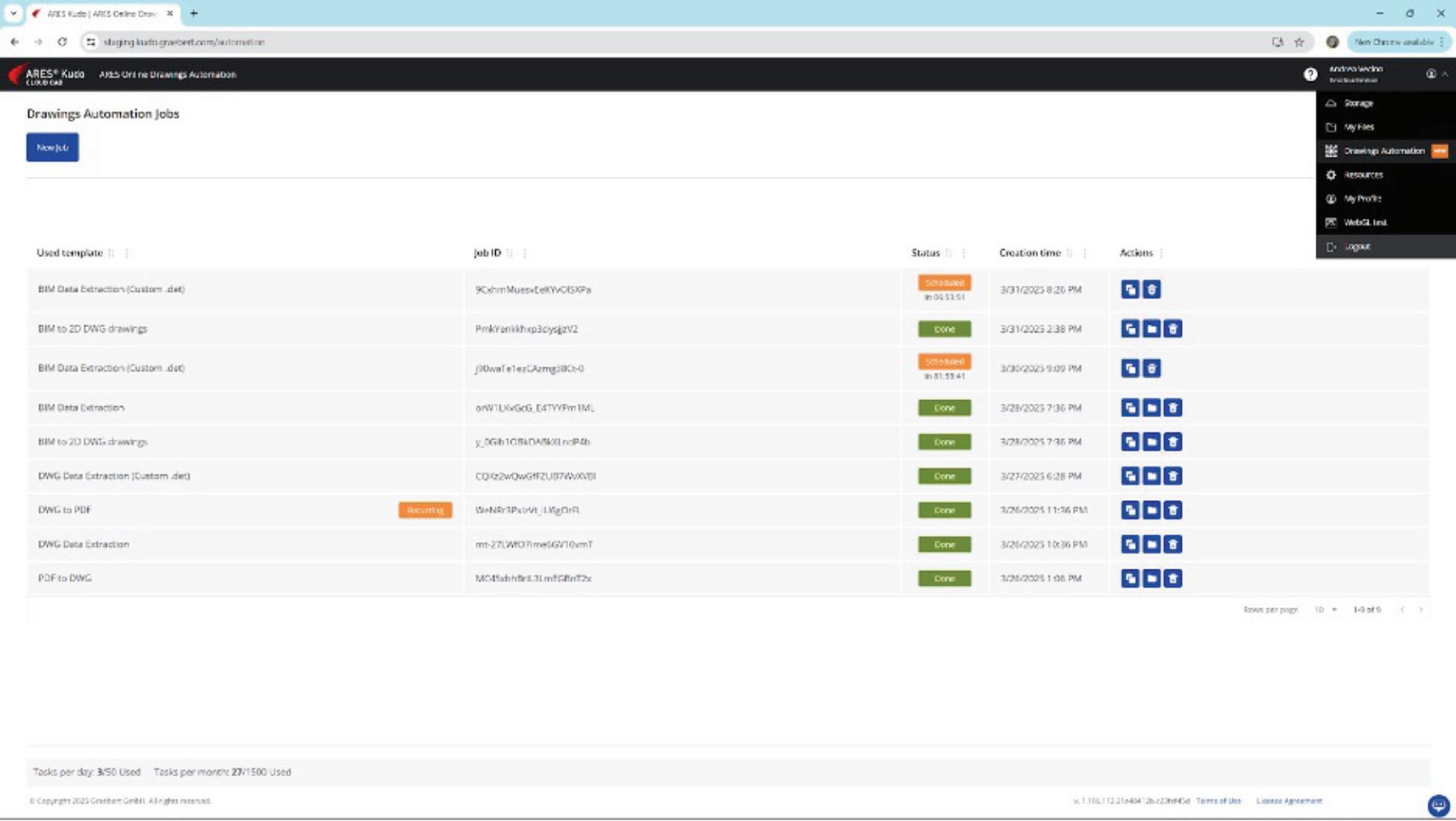
and completion times may vary, depending on the server load.) And for work that must be repeated daily, or at other regular intervals, you can schedule jobs to recur on a consistent basis.
How can these features make a difference in your workplace? Consider a regular routine at an imaginary architecture firm: At the end of each day, someone needs to create new floor plans, sections, and elevations from the updated Revit or IFC file; compare the day’s output with yesterday’s version; highlight differences between the two in color; and finally, create a PDF recap for the project manager’s review. That’s a lot of repetitive work for a human CAD user — or none at all, if it’s automated and scheduled to run on a repeating basis.
AUTOMATION FOR BIM-TO-CAD TASKS AND BEYOND
The Auto-Drawings features in ARES Kudo fall into
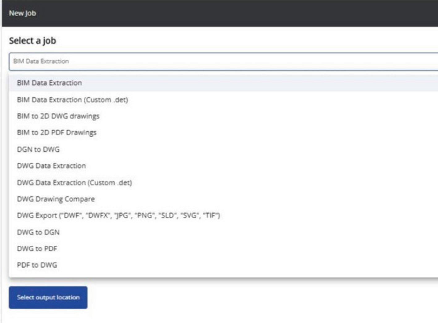
two main categories: CAD-specific features and BIM-specific features. (We are continually expanding our Automation capabilities, so please visit the Automation section within ARES Kudo to see an up-todate list of features.)
The CAD Automation features handle tasks related to DWG files, including:
• converting PDF or DGN files to DWG
• printing DWG files to PDF
• comparing two drawings
• extracting data from DWG files to CSV files for use in Excel.
While many of these tasks can be done manually, automation provides significant improvements in three key areas:
1. Batch Processing: Instead of a user manually processing a single file at a time, automation allows for processing many files in one batch. For example, you could use automation to print many DWG drawings to PDF in one go, saving significant time and effort.
2. Scheduling and Recurring Jobs: You can schedule tasks to start at specific times (e.g., in the middle of the night or during weekends) or on a recurring basis, such as daily or weekly. For example, comparing two drawings is simple enough to do manually, but takes time — and the more frequently you make comparisons, the more time it takes. Automation could handle this task nightly, generating a file each day that highlights differences from the past 24 hours. Similarly, you could have your DWG files automatically printed to PDF every day.
3. Running as a Background Service: Instead of running locally on your device, the job is executed as an online service, relieving your computer from the load. This allows you to continue working on other tasks while the process runs in the background, and you’ll be notified when the task is completed.

Visit the following website to see ARES Kudo’s Automation features in action. www.youtube.com/ watch?v=X7IP0l472Fg&list=PLStPIOsWm9vFjJdp1ul h2Aeqx3NfxR8tS&index=10
The BIM Drawings Automation features focus specifically on BIM-to-CAD tasks, including:
• BIM to DWG: Importing Revit or IFC files and generating 2D drawings in DWG from those BIM files, including floor plans, sections, and elevations with automatic dimensions and labels
• BIM to PDF: If you don’t need to add details and just want to share all the floorplans, sections, and elevations as a PDF
• BIM to Excel: Exporting BIM data to CSV format for use in Excel (or similar programs).
When working in a BIM software application, such as Revit, the user must manually annotate the 2D drawings after extracting them from the BIM model. ARES Kudo, in contrast, automates both the generation of drawings from BIM geometry and the addition of all necessary dimensions and labels.
Niknaz Aftahi, founder and CEO of aec+tech, put it this way during her keynote presentation at Graebert neXt 2025: “Since [BIM Drawings
Automation] reads building data rather than just geometry, it can speed up documentation while reducing the risk of errors. For me as an architect, and also for engineers and project managers, this means spending less time on repetitive tasks and more time on design and decision-making.”
AFTER AUTOMATION, WHAT’S NEXT FOR YOUR FILES?
With ARES Kudo, users have full control over where their files are stored. To determine where the files generated by your Automation tasks will be saved, simply select one of the cloud storage folders that you have connected to ARES Kudo.
After using the BIM Drawings Automation features, if users wish to modify the resulting DWG drawings, they have the full array of ARES Kudo’s 2D CAD tools at their disposal. In addition, ARES Kudo’s intuitive collaboration features make it easy to share, markup, and annotate these files — which is more important than ever, now that more AEC professionals are working remotely than in the past.
“Cloud-based tools, including Cloud CAD, aren’t just desktop software moved into a browser; they go beyond that. They improve collaboration, security, and efficiency,” Aftahi explained. “More teams now
need real-time collaboration tools, and cloud-native tools are not just nice to have — they are pretty essential.”
WHO CAN USE AUTOMATION IN ARES KUDO?
Automation is included for ARES Kudo users at no additional cost. However, usage limits do apply, as explained below, and if you create jobs that batch-process multiple files, each individual file processed counts as a separate task against your daily quota. Similarly, if you set up recurring jobs, every execution of that job will count toward your daily task limit.
The usage limits vary depending on the type of user:
• Free users are allowed up to 5 tasks per day. Please note that the free version of ARES Kudo does not allow for editing the files created through Automation. ARES Kudo’s editing features are only available to subscribers who hold a valid license, and to trial users.
• Trial users and paid subscribers with a valid subscription can perform up to 50 tasks per day.
• Enterprise users can arrange for different limits if needed, as well as more customization; please see the next section for further information.
CUSTOMIZING AUTOMATION FOR LARGER DEPLOYMENTS
The Automation features currently available in ARES Kudo are designed to cover common use cases efficiently. However, we recognize that every organization has unique needs. Enterprise
users have the option to create — with Graebert’s assistance — customized Automation features that specifically cater to those unique requirements. Most commands available in ARES Commander and ARES Kudo can be automated, provided they can be executed from the command bar without requiring manual selections or clicks.
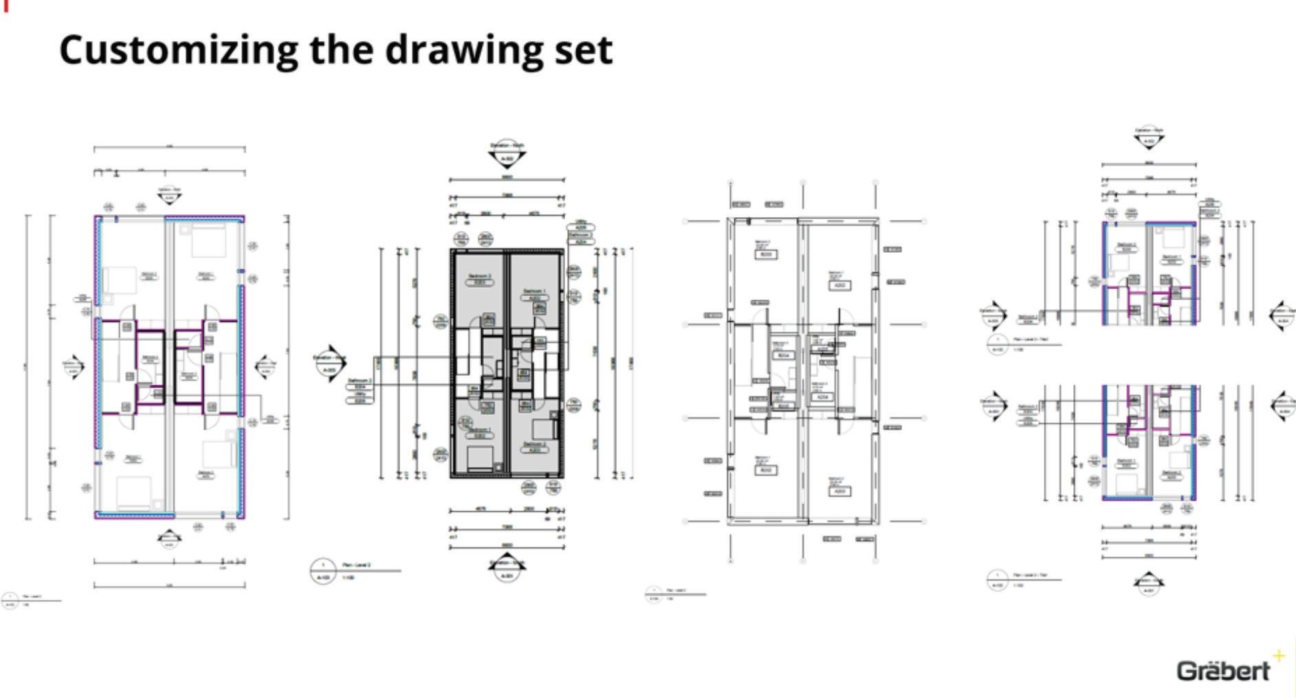
Enterprise customers and developers can further customize the automation of their drawings. For example, this image shows the same floorplan with four different styles, reflecting different settings for the Online Drawings Automation.
The BIM to DWG and BIM to PDF Automation in ARES Kudo apply uniform settings to all drawings by default. For organizations that require more control over those settings, greater customization capabilities, or more task-processing capacity, Enterprise licenses of ARES Kudo open the door to additional Automation options. We invite you to meet with us to discuss how we can better accommodate your operational needs.
Visit the New Features page on the Graebert website at www.graebert.com/cad-software/arescommander/new-features/ to learn more about the Automation features, plus many more new features in ARES 2026. To try them for yourself, simply create your free Graebert account and start your free 30day trial today at www.graebert.com/cad-software/ ares-trinity/account/use/

Cyrena Respini-Irwin covered CAD and related technologies for more than a decade at Cadalyst, where she became Editor in Chief. In 2021 she found a new home at Graebert as the Brand Ambassador for the ARES Trinity of CAD software.
Welcome to AUGIWorld Inside Track! Check out the latest opportunities to advance your skills, processes, and workflows in your firm with the most current AEC-related software and hardware updates available.
Hypar

Hypar made me do a double take. Is it an AI tool, or is it a Revit add-in? Is it intuitively interoperable, or interoperably intuitive? Aaaahhhh, decisions, decisions…
Before I commence my trek to attain some sort of divine clarity, let’s get formal introductions out of the way…
All of you know by now my tendency to gravitate towards free applications. Hypar has a bit of a split personality. It’s free to start - but with the understanding that this is only for limited exploration and evaluation use. Once you’ve decided that it’s for you, you can upgrade (and start paying). Upgrading gives you access to advanced features like: Inside Track by:
Gentle Reader - Hypar and Hypar Add-In
Hypar and Hypar Add-in - Gentle Reader
Hypar is a web based complete space planning toolbox which comes equipped with building and layout libraries and a direct connection to Revit as an add-in. You can create space types, add furniture and equipment from preloaded libraries. A big advantage that Hypar offers is its bi-directionality - you can import and export elements to and from Revit, and export data to an Excel file. It includes an add-in that is compatible with Revit versions 20222025.
Rina Sahay
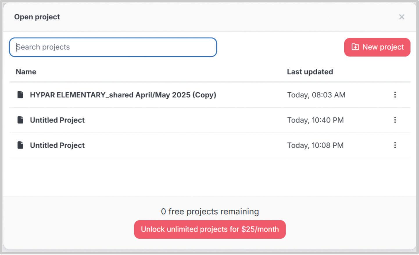
• Unlimited projects (with the free version you may not make, share or
• keep more than 3 projects at a time)
• Create multiple Design Options
• Specify clearances
• Automatically detect clashes
• Share the project with multiple stakeholders using live links.
Let’s get started! First of all, you need to go to the Hypar website and sign up for an account. Once you receive a confirmatory email, you will be able to access the Hypar editor.
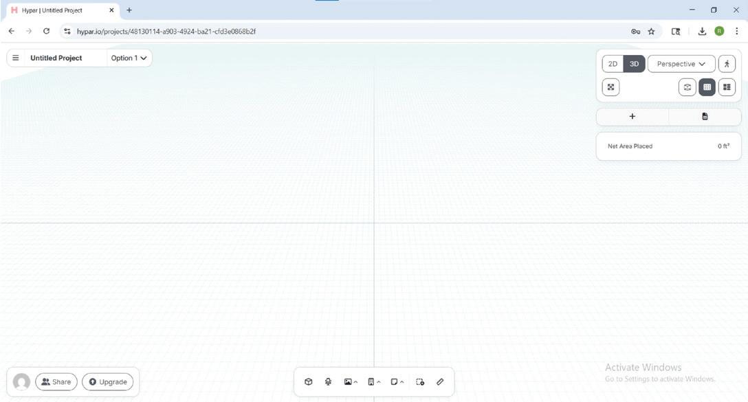
This is the environment you will work in. Let’s examine the interface! Starting from the top left corner….
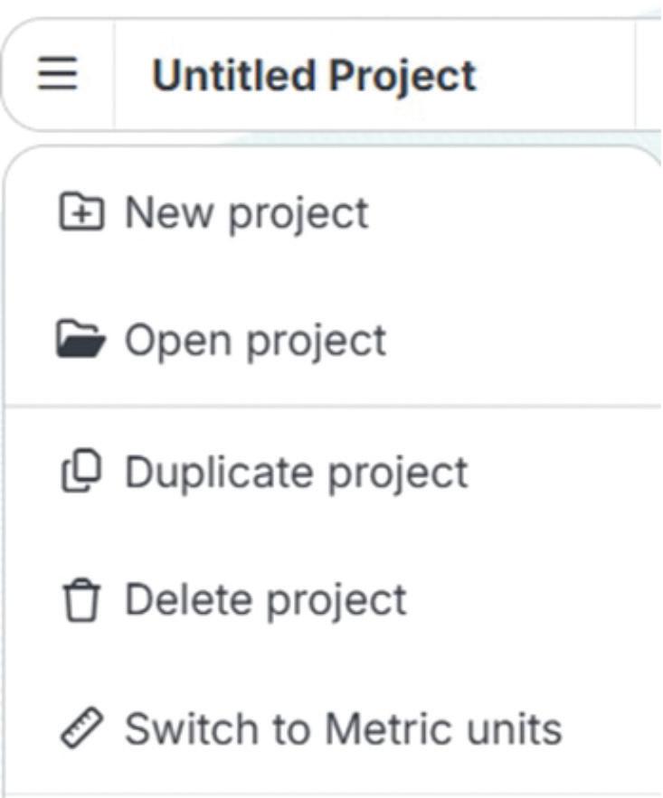
You have options to start, open, duplicate, or delete projects. You can also perform all of these actions simply by clicking Open Project which gives you all of these options in one nice tidy place, and to my mind, a lot more control.
TIP - You can open multiple windows with different projects.

You can Import Revit furniture, equipment, and rooms, among other things - of course, these operations would need the Revit add-in.

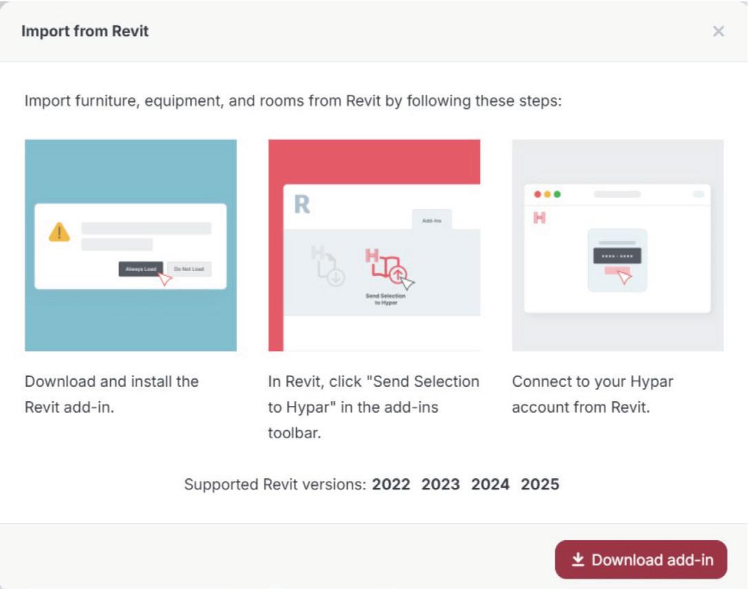

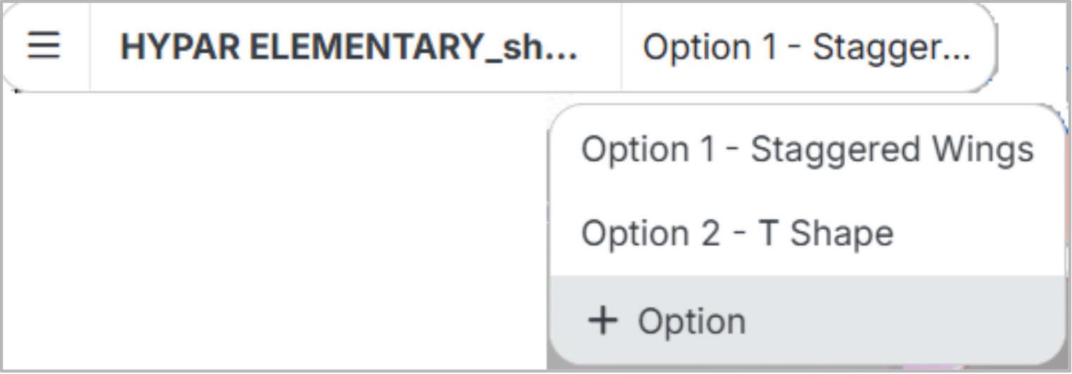
We’ll take a quick look at the Revit add-in in a bit! You can add and toggle between Design Options. I was able to explore this option in the sample file provided.
On to the top right-hand corner! A one-stop shop for View controls!
You can toggle between 2D and 3D views - and the 2D views are already tagged with names and areas for you!
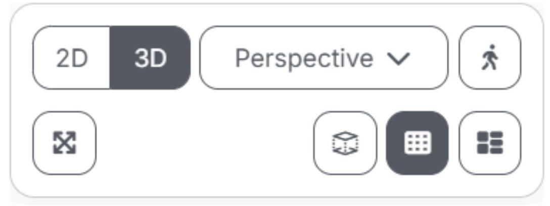
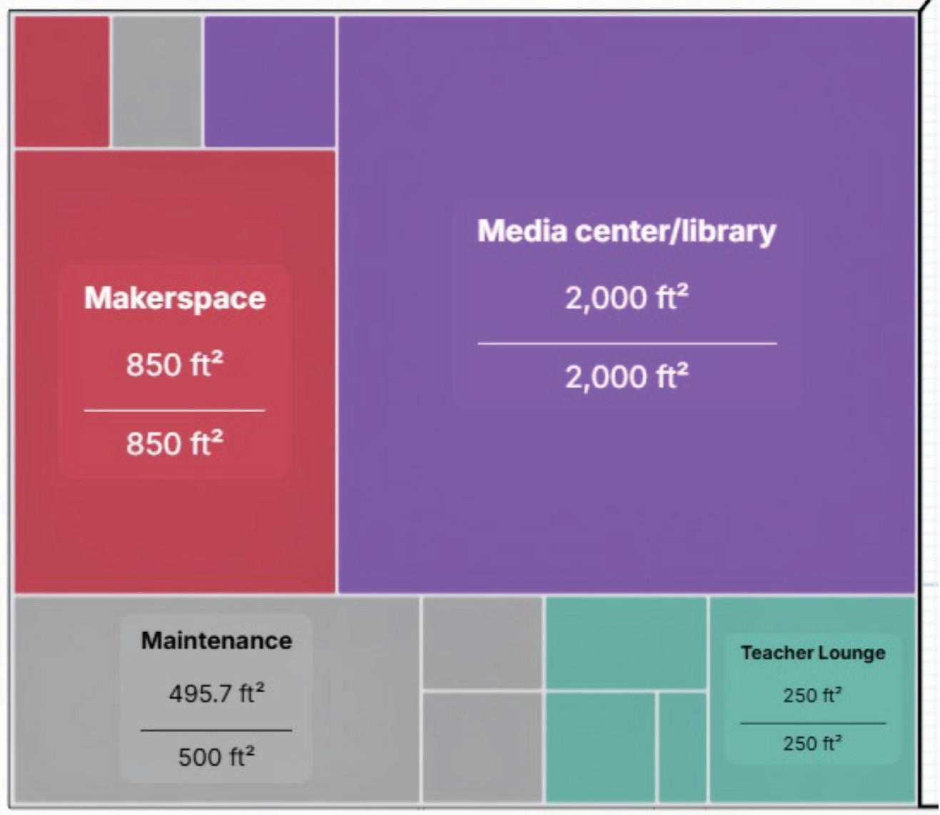
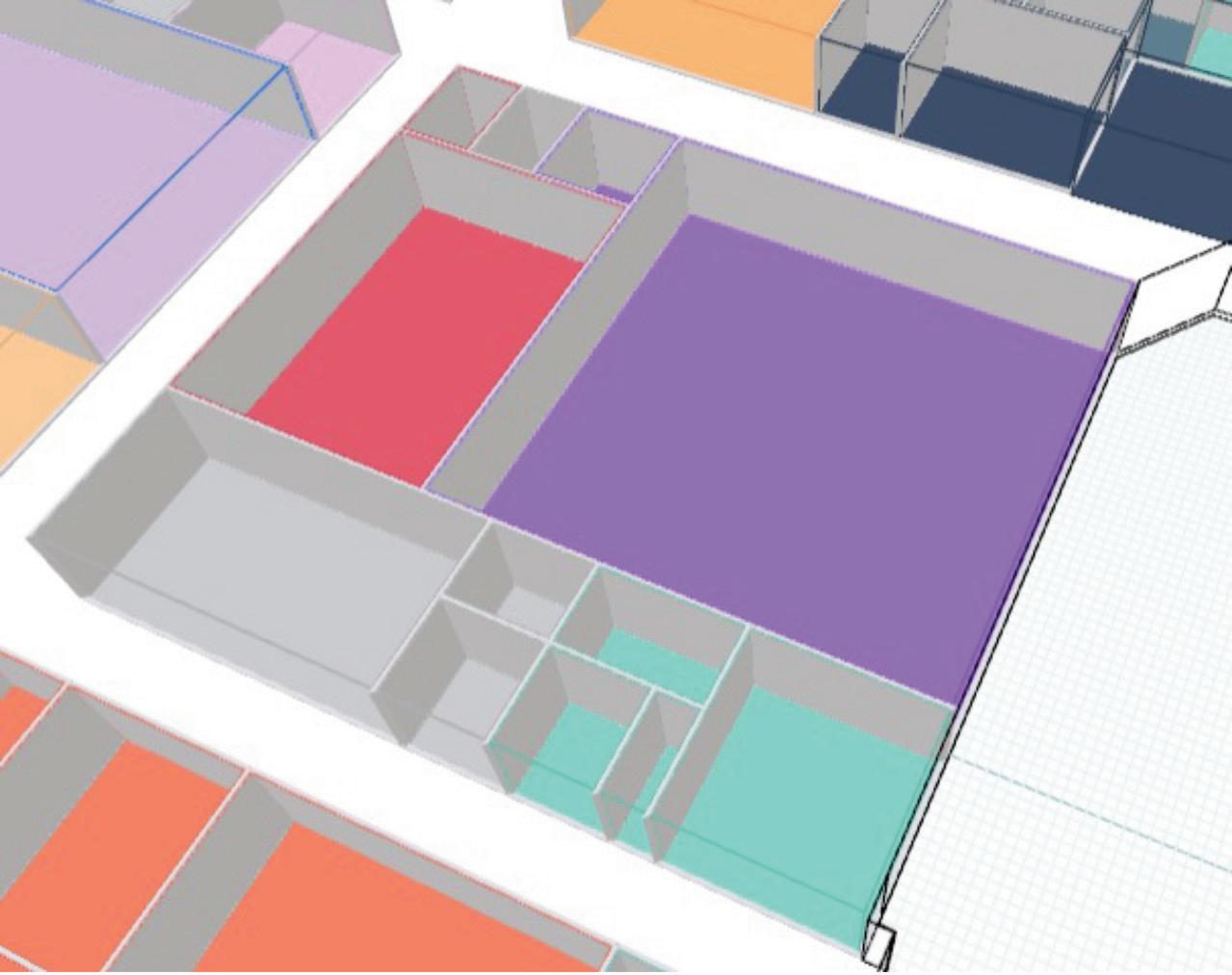
…and between Orthographic and Perspective Views! You can Zoom to Fit Project, view an Exploded View, and hide the grid as needed.

You can add Program Requirements - that is, different space types. Look at the bottom of the Search palette (tip - in a new Project the Search
palette does not exist - all you see is a little + button to add Program Requirements) to add, import requirements from a spreadsheet, or export metrics to Excel.

Select a space type and click Insert in Project to place it in the model - or just drag from the palette to the model. The palette also shows you the number of spaces of each type that have been placed in the model.
And we mustn’t forget the nifty little box that gives us information about Gross and Net Floor Area Placed!

Here’s the real power of Hypar - its editing tools.
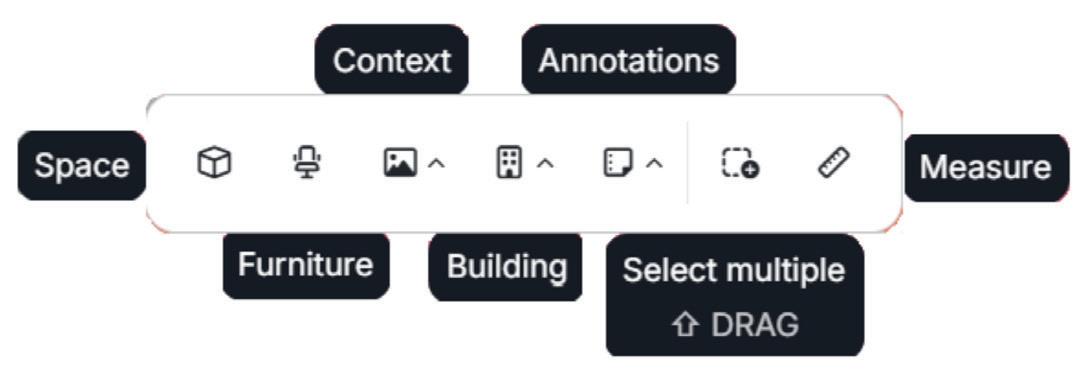
The Furniture tool is particularly eye-catching - it gives access to a preloaded furniture Workplace and Healthcare library. No more loading families!
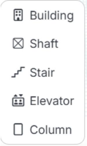
The Building tool gives you options to create a

whole new Building, or Shafts, Stairs, Elevators, and Columns.
To Share projects - click on the button at the bottom left corner of your screen.


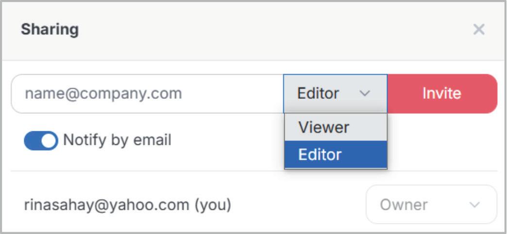
To get you started. Hypar has provided a sample file to play with! (Here’s what I noticed - you can duplicate the browser window to open multiple projects, but you can’t open the same project in multiple windows!)
LESSONS LEARNED FROM THE SAMPLE FILE
Some of the things that you can do -
• Use the Building tool to start with the building
Inside Track
footprint. Click the Edit Shape button to edit the shape of the building.
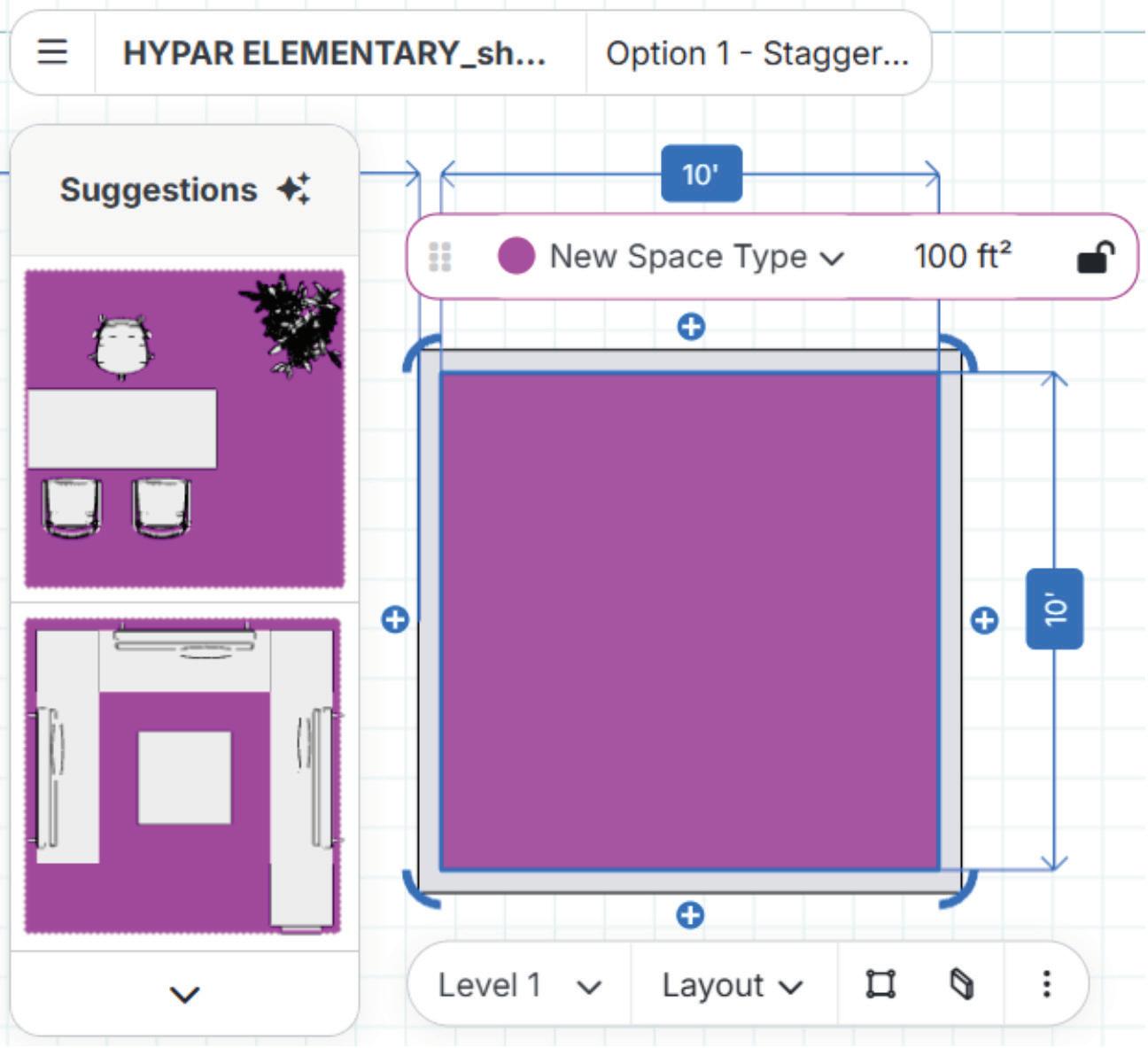
• Add Program Requirements. You can specify and constrain the area of each room type by locking it. Click to unlock if you want to edit the area.
• Select placed rooms. Drag to resize. You can swap Levels and Space Types. Click the little Walls icon to add, remove, or edit Walls.
Take a look at the room layout Suggestions. You also get suggestions when you place a grid line, or a column at the intersection of two grid lines. Select, accept, and edit as needed. Lather, rinse, and repeat.
WORKING WITH REVIT
The Export to Revit tool takes us to a prompt to download the add-in.


Pick the Revit versions you need from the dialog box.
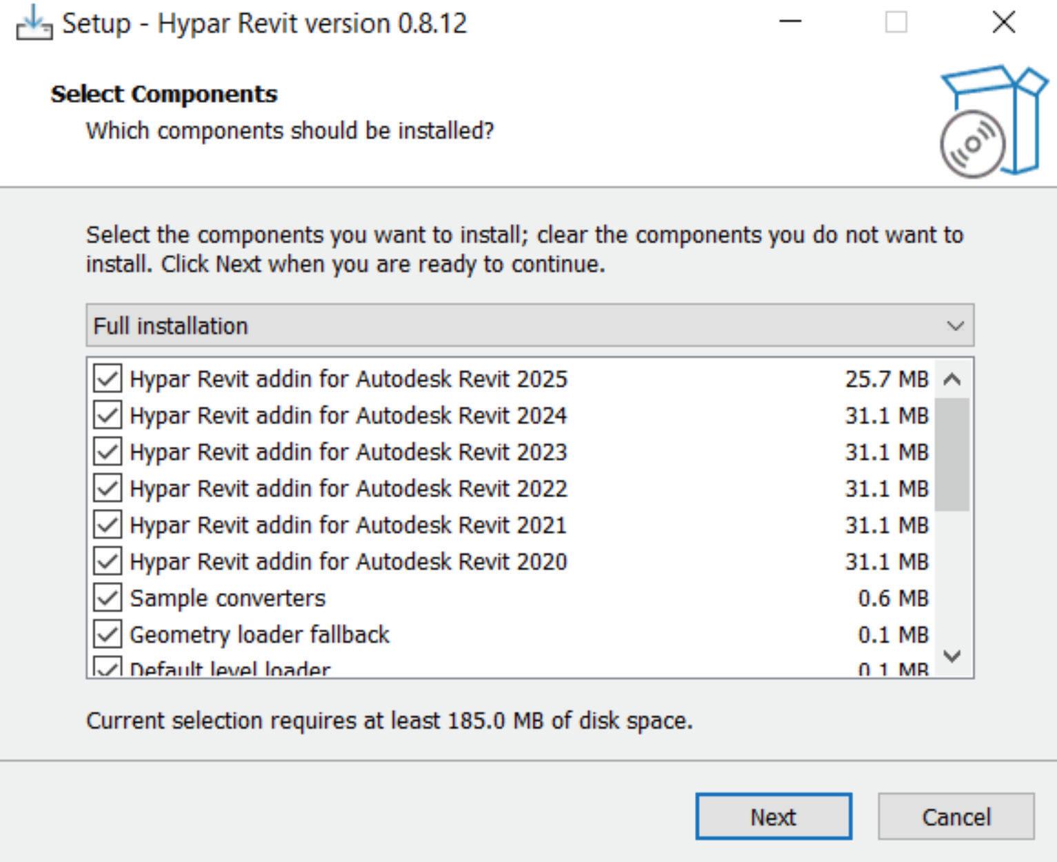
You will see the Hypar buttons in the Add-Ins tab in Revit.

You will be prompted to authorize a login codeand then log in

Once you have logged in you will see Hypar’s Open Project dialog box in Revit. Select the required project.
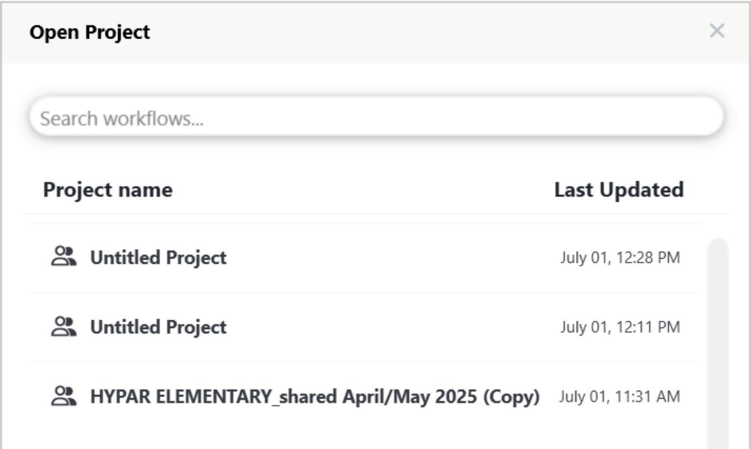
Select the desired Design Option and Load. Voila! The Hypar model is in Revit!
Conversely - you can select elements in the Revit model and send them to Hypar. Hypar will prompt you to Add from Revit. Click Place and you can place the selected elements exactly where you want them to be. Nice, right?


So, what is the point of this seemingly aimless and endless perambulation around The Land of Hypar? I think (and you are absolutely free to differ from my opinion) that this tool addresses an actual need. I’ve always felt - and have heard opinions - that Revit is an awesome authoring tool for production, but much too convoluted for the designers - who don’t need a fraction of Revit’s tools anyway.
Hypar gives designers a simple, intuitive environment to get DD phase models and layouts in place, which can then be brought into Revit for final processing. Some advantages - fewer Revit licenses, designer machines requiring less firepower, speedier design workflows, and a general cessation in the symptoms of the rare and exotic malady known as Revit Designer Panic.
On that note, I now bid thee farewell, O Gentle Reader! Till the next issue of Inside Track - KEEP REVIT-ING!

A bit about myself. I’m a BIM Manager on The Loose (need a BIM Manager, anyone?), based in glorious Grand Rapids, Michigan (Great Lakes, anyone?). Started my Autodesk journey with AutoCAD Release 10 (remember that dreary DOS interface - and the need for super-duper spelling skills?). Learned enough Revit to stay one chapter ahead of college students in the classroom. That changed in a hurry when I made a triumphantly painful return to industry as a BIM Specialist and had to use Revit in the worst way possible. I HATED it and grieved for my beloved AutoCAD Until I figured Revit out - the rest, as they say, is history. Autodesk Expert Elite in 2018, presenter at Autodesk University since AU2019 (and I have Best Speaker awards for 2021 and 2022 to show for it!). And now here I am, to educate, enlighten, and hopefully, entertain.
Please let us know if you have some news to share with us for future issues. Likewise, if you are a featured product or news item user and would like to write a review, we want to know. Drop me a line at: rina.sahay@augi.com. We'd love to hear from you!
Automate Information Management by Dynamo in Civil 3D

Automated data management in Civil 3D through Dynamo represents a critical area for improving project team efficiency. This article provides practical introduction to workflows for implementing automated processes that eliminate routine tasks and minimize errors in project data handling.
Before diving into the Dynamo workflow, it’s worth mentioning that Autodesk provides the Standardized Data Tool for property set management. However, from field experience, many users prefer developing their own customized tools using Dynamo. This approach offers greater flexibility to adapt workflows to specific project requirements and organizational standards.
Modern infrastructure projects require processing extensive datasets encompassing complex utility networks, terrain models, and associated project documentation. While Civil 3D offers advanced design capabilities, manual property management often leads to inefficiencies and potential errors that can impact deliverable quality.
Dynamo for Civil 3D addresses these challenges through visual programming that enables automated data processing workflows. The tool allows engineers to create custom solutions for reading, modifying, and organizing project information without requiring extensive programming experience.
The workflows demonstrated the target Civil 3D 2026, which includes over 1,000 new Dynamo nodes added after updates in 2025.1 and 2025.2 versions that significantly expand automation capabilities. All examples utilize native Dynamo functionality without requiring additional packages, ensuring broad accessibility and compatibility across different organizational environments.
From practical experience, Civil 3D models typically contain substantial numbers of 3D solid objects representing various infrastructure elements such as manholes, culverts, retaining structures, utility components, road structures, pavement layers, terrain features, and other structural layers. These solids often require consistent property assignment, material definitions, and organizational structure. This article focuses specifically on automated workflows for managing 3D solid objects, addressing common challenges in property standardization and bulk modifications that frequently arise in production environments.
The implementation of Dynamo-based automation delivers measurable benefits: reduced manual data entry, improved data consistency across project phases, and standardized workflows suitable for organization-wide deployment. Through Dynamo’s node-based interface, professionals can develop sophisticated automation solutions regardless of their programming background.
This article presents fundamental concepts and basic implementations, advancing to recommendations of techniques that integrate external data sources including Excel spreadsheets.
PROPERTY SET DEFINITION 1, MANUAL AND AUTOMATIC PROPERTY DEFINITIONS
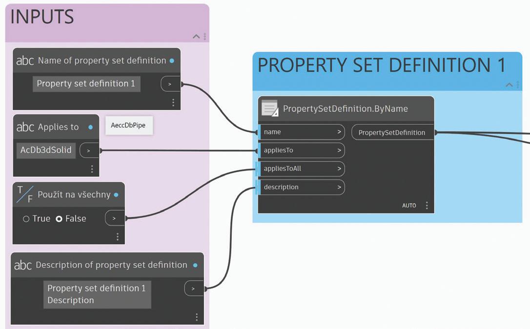
Let’s start with the first example demonstrating the current possibilities for defining property set definitions and property definitions. Unlike previous versions, there is no longer a requirement to use external packages. The most important aspect is establishing a proper blueprint for future project work based on mandatory project requirements, making Excel import preferable for large numbers of definitions. Here we begin with a simple example, and in the second part of this article we will focus on workflows and ideas using Excel.
We start with property set definitions and then continue with property definitions.
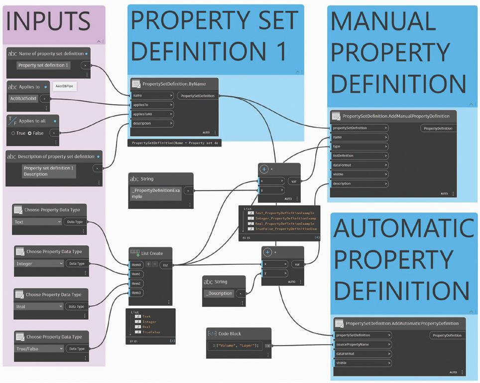

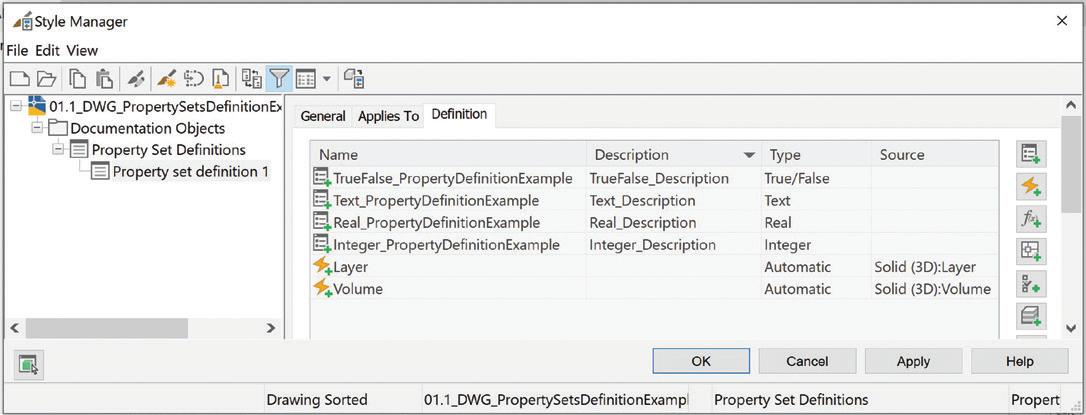
For automatic properties, you need to know which automatic properties are available for the given object type. I recommend using the Property Set Style Manager from the Manage tab to manually create automatic property definitions, where you can see the complete list of available properties according to the object type they apply to. This
Figure 1: Property Set Definition
Figure 2: Manual and Automatic Property Definition
Figure 3: Manual Property Definition
Dynamo in Civil 3D
approach helps you identify the correct property names and syntax before implementing them in your Dynamo workflow. Once you understand the available automatic properties through the manual interface, you can then replicate the same functionality in Dynamo with confidence.

In the Style Manager window, you can see the result after you run the Dynamo graph.
PROPERTY SET DEFINITION 2, LIST DEFINITION
We continue with the second example of property set definition. Here the important workflow demonstrates how to create new lists of property definition values. This prevents mistakes and gives information managers the possibility to prepare values using Dynamo but imagine doing this

manually for a large number of values - it could be very boring and time-consuming.
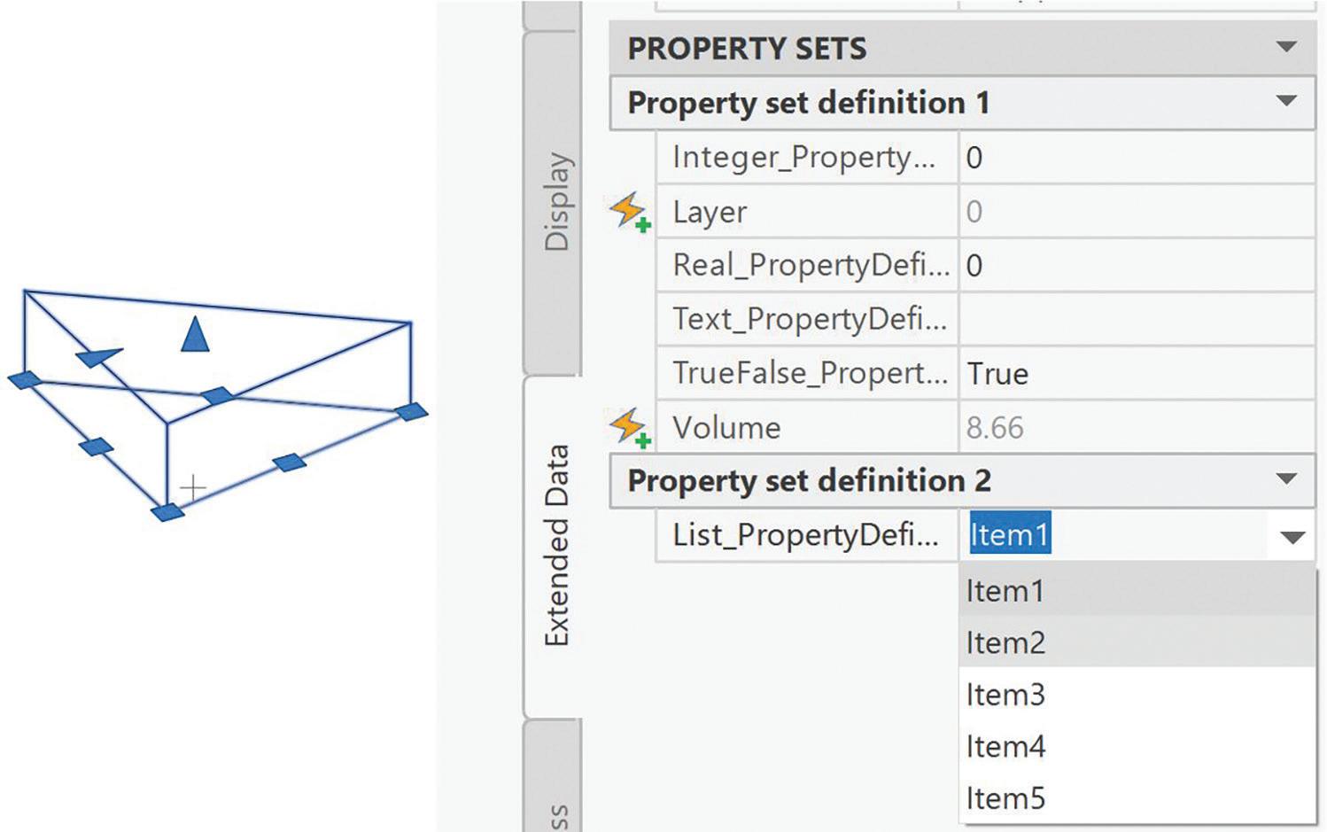
Very important is the ListDefinition.ByNameItems node and its input allowItemsToVary, where you can set the possibility to overwrite text input from the given list, making it prepared for special situations as well. This flexibility allows users to either select from predefined options or enter custom values when needed, providing both standardization and adaptability in your property management workflow.

In the Style Manager, there is still the possibility to make any necessary adjustments. Here is a picture showing the results after the Dynamo graph was run.

ADD PROPERTY SETS TO OBJECTS
Once you’ve created your property set definitions and property definitions, applying them to objects requires the Object.AddPropertySet node. While you can select objects directly in Civil 3D, I recommend building a workflow with Excel where each object layer serves as an identifier with
Figure 4: Automatic Property Definition
Figure 7: Property Set Definition 2 and List Definition
Figure 8: Property Set Definition 2 and List Definition in StyleManager
Figure 5: Pset Style Manager
Figure 6: List Definition
corresponding property set names listed on the same row. This approach provides better control and documentation of which property sets apply to specific object types.

The result is visible in Civil 3D properties window under Extended data tab.
REMOVE PROPERTY SETS FROM OBJECTS
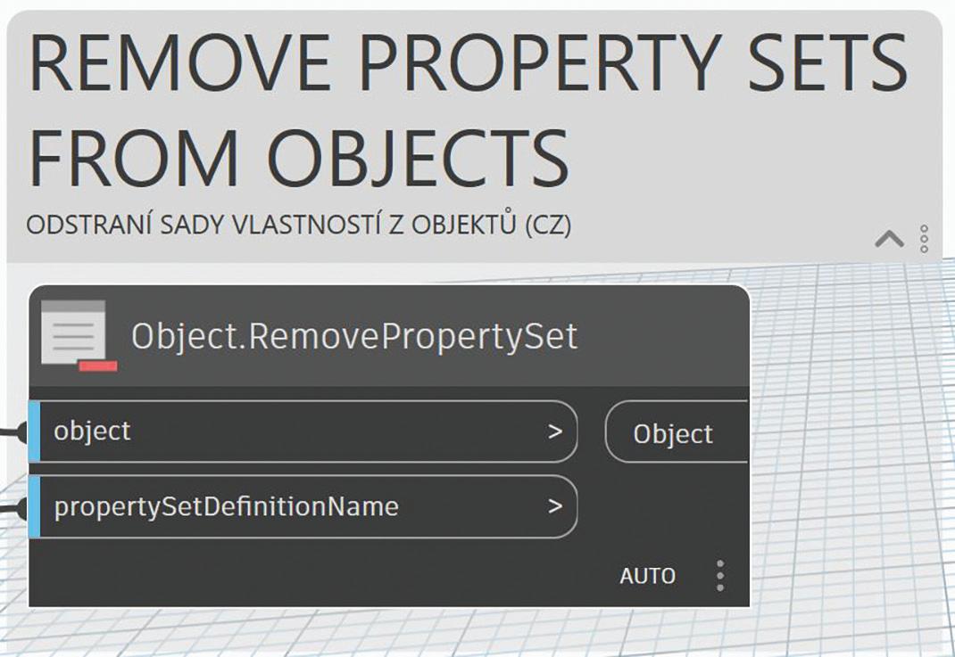
Property set removal uses the Object. RemovePropertySet node to detach property sets from selected objects. Sometimes you need to start from the beginning or clean your model, and this is the most elegant way with Dynamo. When objects have different numbers of property sets attached, manual removal becomes impossible to manage efficiently. I recommend using a similar Excelbased workflow for adding property sets, where
you define objects by layer and specify property set names to remove.
EXPORT OBJECTS DATA TO EXCEL
I recommend implementing a data export workflow that utilizes the Object.PropertyData node to extract property values from selected objects. This enables analysis of manually added property values and allows team members without Civil 3D skills to contribute data by simply filling or changing values in Excel cells. Connect this to Excel writing nodes to create spreadsheets containing all property information, though the specific node connections and detailed setup are beyond the scope of this article. The exported data includes object handle
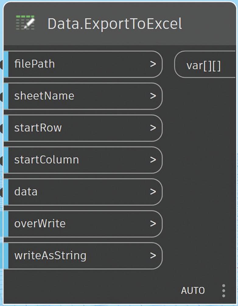
Figure 9; Add property sets to objects
Figure 10. Extended Data C3D Properties
Figure 11: Remove property sets from objects
Figure 12: Export Data to Excel

values that provide exact identification of each object for subsequent Dynamo workflows to import data from Excel. This approach creates a collaborative workflow where responsible parties can update property values externally while maintaining precise object tracking.
Figure 13 shows an example of such Excel data exported from the DWG file described previously in this article.
IMPORT DATA FROM EXCEL AND UPDATE PROPERTY VALUES
I recommend implementing an Excel import workflow where property values have been added or modified externally, though the complexity and scope prevent detailed coverage in this article. The
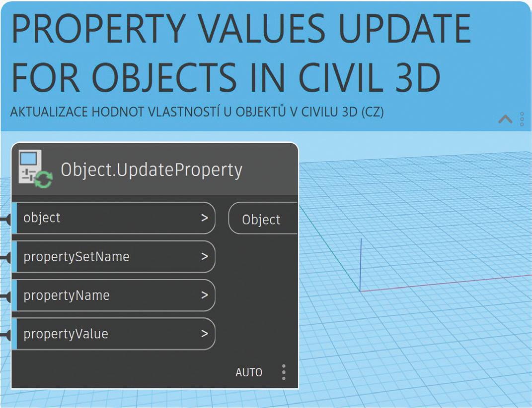

Figure 13: Excel
Figure 14: Import Data from Excel

import process reverses the export workflow using Data.ImportExcel and Object.UpdateProperty nodes to read spreadsheet data and match it to corresponding objects and properties in your model. This enables bulk property updates from external sources or collaborative editing workflows where team members can contribute data without Civil 3D access. Property values update automatically based on the Excel data, maintaining data consistency across your project.
CONCLUSION
In Civil 3D, as mentioned at the beginning, there are multiple possibilities for working with property sets. From my experience, I recommend Dynamo because you can automate a lot of workflows and have the freedom to implement changes quickly. This workflow helps you sleep better when managing complex projects where requirements and tasks frequently change during development.
This is my first article for AUGI and the Civil 3D user community. I welcome any feedback to help finetune future articles to be more useful for you. With my team at Graitec (Autodesk Platinum Partner), we prepare more detail content and training in multiple languages including English, Spanish, Portuguese, and Czech - let me know if you’re interested.
I look forward to seeing how this topic resonates within the Civil 3D user and BIM information management communities.

Lukas Drbohlav is a civil engineer who graduated from Czech Technical University specializing in water management and hydraulic structures. He began his career working on environmental construction projects including land reclamation, remediation, terrain modifications, and sewerage systems for 5 years, where he became passionate about Civil 3D starting with the 2009 version.
Currently serving as Services Manager for AEC Infrastructure EMEA at Graitec, an Autodesk Platinum Partner, he brings 8 years of experience in consulting and management roles. His expertise spans complex project delivery, team leadership, and developing innovative approaches to streamline design processes through technology integration. He enjoys helping others discover ways to simplify their work, which he has been doing for Graitec customers for the past 8 years.
With extensive field experience in infrastructure consulting, Lukas Drbohlav focuses on helping engineering teams optimize their workflows through strategic implementation of Autodesk solutions. His practical approach to problem-solving and deep understanding of project challenges makes him a trusted advisor for organizations looking to enhance their design efficiency and data management capabilities.
Contact Lukas Drbohlav at lukas.drbohlav@graitec.com or connect via LinkedIn at https://www.linkedin.com/in/ lukas-d-49558696/
Figure 15: Update Property
Free SamplesThe Summer Edition

SUMMER BEGINS
I’ve always looked forward to Summer. During my younger years I remember having to start the school year at the beginning of Fall. Attending classes continued through both the Winter & Spring seasons. Finally, when Summertime rolled around all the classes were over. There was no longer a need to complete homework assignments or study for pop quizzes and exams. Then after I graduated and started employment in my career field, I continued to look forward to Summer because that’s when daylight lasts the longest. As early as 6:00 am in the morning the sun would rise. There would be plenty of daylight until the sun eventually set well after 8:00 pm. So whenever I was able to leave work on time there would still be an additional 2 to 3 hours of daylight available for me to enjoy. Likewise in this Summer edition of free samples I’ll be pointing out three free open-source lisp functions that have accompanied AutoCAD for a very long time with lasting impact even to the current version of AutoCAD.
FREE STUFF
Well, it has been a couple of years now since I first started on the “Free Samples” series. In these articles I review the many open source lisp files that come packaged with AutoCAD free for the taking. This time I’m going to continue the “Free Samples” series by focusing on three open-source lisp routines that were introduced in different versions of AutoCAD. Like my previous “Free Samples” articles, I’ll first introduce the lisp command, explain what it does and discuss what came of it as AutoCAD continues to develop to the current version.
1. DELLAYER / LAYDEL
Since the initial release back in 1982 Layers have always been an important feature offered in AutoCAD. Not only did AutoCAD provide the ability to name Layers but also to manipulate their properties like turning them Off or On. Then with the introduction of AutoLISP in version 2.18, AutoCAD by version 2.6 included a free open-source lisp file called DelLayer.lsp (see Figure 1).

Figure 1
The name of the added command is a bit deceiving. Because DelLayer does not actually delete the Layer itself. But instead with these few lines of code it added the ability to delete all the objects on a given Layer. With each release of AutoCAD starting with version 2.6 to R12 the DelLayer.lsp grew not only in the number of lines of code but also in added function. Though the code still fell short of actually deleting the Layer itself, the R12 version of the code finally prepared the groundwork for the Layer to be deleted or purged. It also added support to delete objects on the given Layer both in Model Space and Paper Space (see Figure 2).
Then for some reason in both AutoCAD R13 and R14 this free sample code completely disappeared from the shipped package. It wasn’t until AutoCAD 2000


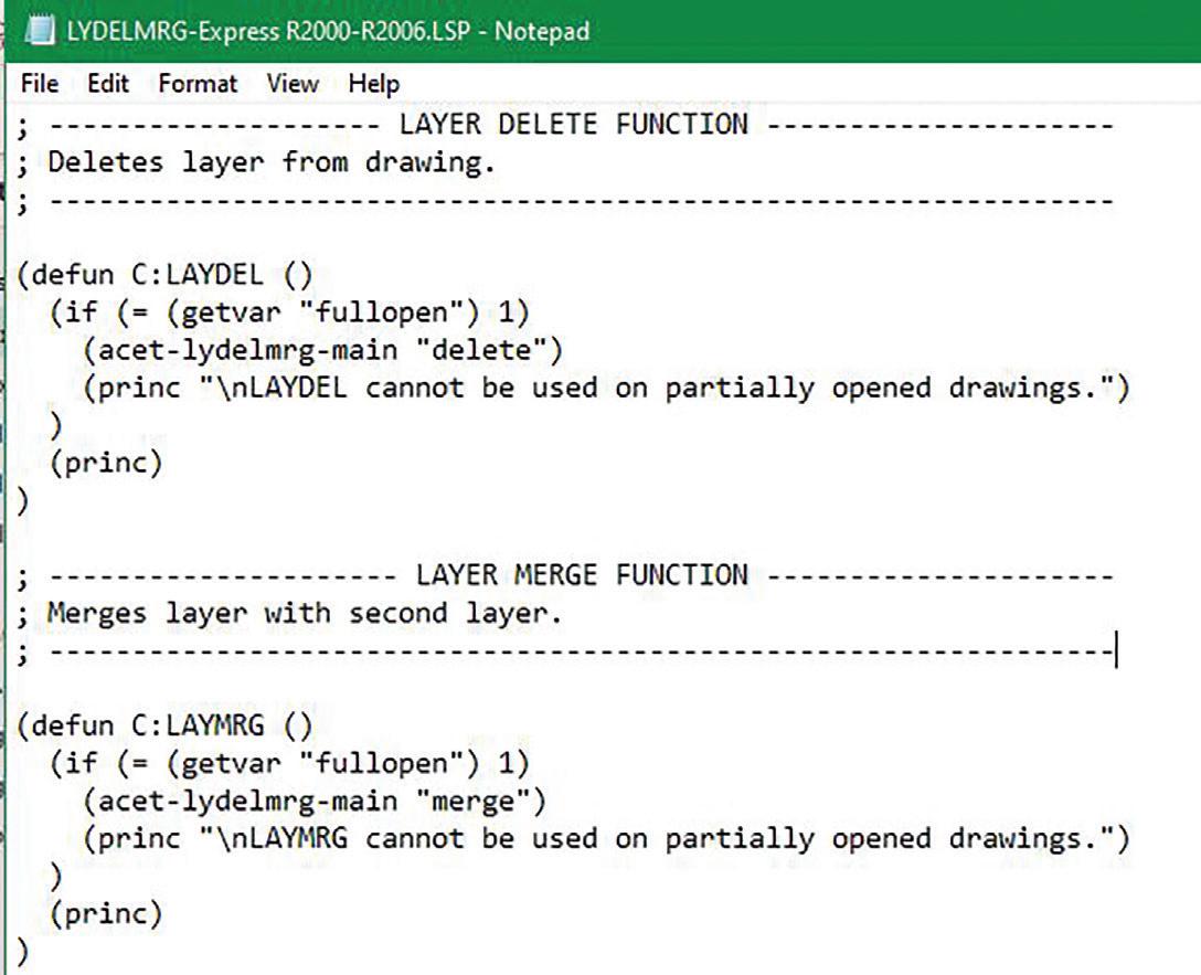
4 was released with the added Express Tools did a similar open-source lisp function return with a new name called LayDel (see Figure 3).

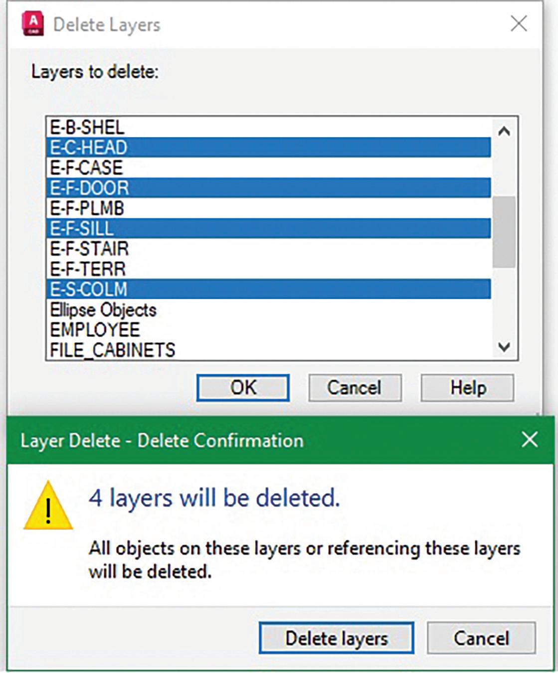
6
Figure 5
Figure 2
Figure 3
Figure
Figure


This time the open-source lisp code is saved under a file called LyDelMrg.lsp. In addition to LayDel the file now contains an additional Layer command called LayMrg (see Figure 4).
Finally LayDel not only deletes objects on a specific Layer but also the Layer itself. It finally lives up to the meaning behind the command name. This addition, along with a few other Express Tools Layer functions, got so popular and useful that by AutoCAD 2007 they were all incorporated as built-in AutoCAD commands.


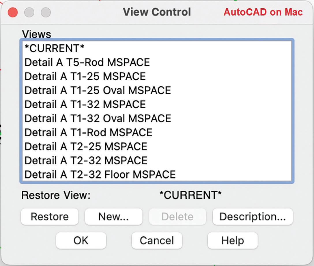
Figure 7
Figure 9
Figure 8
Figure 10
Figure 11
Figure 12
Note that the LayDel command is different than the Delete Layer command found on the right mouse click hidden context menu within the Layer Properties Manager window. Though this command can be executed on multiple Layers selected, it cannot delete a Layer if there are any objects including those inside Blocks that still occupy the Layer (see Figure 5).
On the other hand, the LayDel command can successfully delete Layers even when there are objects occupying the Layer from inside a Block. So be very careful when executing the LayDel command. You may end up losing very valuable information and without a clue as to what happened (see Figure 6).
2. DDVIEW
The View command was first introduced in AutoCAD version 2.5. It offered the option to save the current View with a given name so that it can then be restored onto the graphics screen for viewing at a later date. The same View name can also be designated as the Plot Area (see Figure 7).
Initially the View command like all the typical AutoCAD commands was command line driven. To restore the saved View to the current screen you’ll have to manually type in the exact matching View name on the command line in order to successfully complete the operation. Then came AutoCAD R12 adding support for Dialog Control Language (DCL) to customize dialog boxes. So instead of having to type the entries at the command line, there’s a GUI to assist the user in making selections on the screen. R12 shipped with a number of open-source dialog custom commands and one of these was called DDView.lsp (see Figure 8).
After entering on the command line DDView a dialog box appears on the screen. The main body shows a list of saved View names. Then there’s a row of buttons on the bottom with operations matching the prompts of the View command (see Figure 9).
The free open source DDView lisp and DCL files continue to ship with the product until AutoCAD 2000. This is when finally, the built in View command had its own dialog window. The original command line version can still be executed by preceding the command with a hyphen:


Command: -VIEW
Figure 13
Figure 14
Figure 15
Figure 16

The new View command window shows two tabs on the top of the screen offering the option to see the View names organized by Orthographic & Isometric Views. The list of all the View names is still shown in the main body of the window. The buttons labelled with the View operations are now positioned on the right (see Figure 10).
Notice that the Delete button is no longer clustered with the other View operation buttons. Instead, this new dialog window’s View list supports Microsoft’s ever popular right mouse click hidden menu feature. This is where you will find the option to select the Delete operation.
This new View window did not change until AutoCAD 2007 when it received a major facelift. Now with the window labelled as View Manager, the two tabs on the top of the window have been dropped. The View name listing column shifts to the left. The listing is also categorized by Model, Layout and Preset orthographic
Views shown in a tree like format. The middle column now shows the Description or Detail of the selected View. With the operation buttons still positioned on the right the Delete button is back by popular demand. Also, additional View options like Update Layers and Edit Boundaries have been added (see Figure 11).
Though the original DDView lisp and DCL files are no longer shipped with AutoCAD, I’m glad I kept them around. Recently there was a post on Autodesk’s AutoCAD Mac forum (https://forums. autodesk.com/t5/autocad-for-mac-forum/namedviewports-not-showing/m-p/13606501) where an AutoCAD user requested for a View dialog box GUI missing on the Mac version. I was able to successfully make some simple modifications on both the lisp and DCL files and now DDView lives on in AutoCAD on the Mac (see Figure 12).
3. SETUP / MVSETUP
Figure 17
It can be difficult to start a drawing from scratch. Not only do you have to make sure all the typical settings required are present to make the process efficient and conforming, but it also can be quite daunting staring at nothingness on the drawing screen. It’s similar to writers when attempting to start their first sentence. It’s so easy to have writers block looking at a blank page making it very difficult to begin. Perhaps this is why as early as version 2.5 AutoCAD shipped with an open-source lisp file called Setup.lsp (see Figure 13).
When this file executes, you’re prompted with a number of questions such as drawing Units, Scale and Paper size ending with a boundary line representing your drawing area created on the screen to jumpstart your drawing assignment (see Figure 14).
Notice the Setup command sequence relies heavily on responding to the prompts by selecting options from the Screen Menu. The Screen Menu was a column on the far right of the drawing area where additional text commands can be selected. In those early days of AutoCAD the Screen Menu was heavily used until it was eventually replaced by AutoCAD’s

Figure 18


GUI menus (see Figure 15).
The setup process was further enhanced in AutoCAD R11 after the Paper Space feature was added. A revised and renamed MVSetup.lsp file now accompanies the release (see Figure 16).
The free open source MVsetup function continues to develop and improve in each AutoCAD release till today’s AutoCAD 2026. In addition to setting up paper size borders in Model Space a different set of questions are presented to set up Viewports and Title Blocks in Paper Space. Since the Screen Menu is now obsolete, the responses to all the command prompts rely heavily on the Text window to review options offered (see Figure 17).
MY DDSETUP
The obvious drawback to the MVSetup command is that there is no GUI to facilitate the entire process. This is why I came up with my own customized DDSetup lsp function. Unlike AutoCAD’s many typical dialog-based functions that require a separate DCL file to execute, my DDSetup command creates the DCL file on the fly when the command is invoked. Then when the dialog box is dismissed the DCL file generated is deleted. DDSetup presents a window with selections that are visually interactive so the results can be seen on the screen prior to execution (see Figure 18).
Figure 20
Figure 21
DDSetup Dialog Interactive Example 1:
On the top of the DDSetup window under the Measuring Standards section when the Imperial vs Metric radio button is selected the following selection changes occur:
1. Under Measuring Scale: The Scale drop down list would change to reflect a number of standard Imperial vs Metric scales (see Figure 19)
2. Under Sheet Information: The Size drop down list would change to reflect standard Imperial vs Metric paper sizes (see Figure 20)
DDSetup Dialog Interactive Example 2:
On the middle of the DDSetup window under the Sheet Information and Orientation section when the Landscape vs Portrait radio button is selected the following selection changes occur:
1. Under Size: The drop-down list would change to reflect Landscape vs Portrait paper sizes (see Figure 21)
2. Under Sheet: The slide image would change to reflect borders drawn in Landscape vs Portrait orientation (see Figure 21)
My DDSetup app is free and available to download at the Autodesk App Store: https://apps.autodesk. com/ACD/en/Detail/Index?id=2906700119618634204 &appLang=en&os=Win32_64
SUMMER CONTINUES
Each of the three open-source lisp commands discussed have long lasting impact on AutoCAD. Deleting Layers transformed from a few lines of code to a built-in AutoCAD command. The View dialog box window initially introduced in AutoCAD R12 now lives on in AutoCAD on the Mac. A setup command continues to accompany AutoCAD as an open-source lisp file. I’ve placed

in a table summarizing the developmental process (see Figure 22).
Hopefully I’ve again piqued your interest in the many free sample lisp files available from previous up to the current version of AutoCAD. So, during the longer days of Summer, I hope after reading this article you would now be interested to spend the extra available daylight hours to explore the many free samples that still come released with AutoCAD.

Mr. Paul Li graduated in 1988 from the University of Southern California with a Bachelor of Architecture degree. He worked in the Architectural field for small to midsize global firms for over 33 years. Throughout his tenure in Architecture, he has mastered the use and customization of AutoCAD. Using AutoLISP/ Visual Lisp combined with Dialog Control Language (DCL) programming he has developed a number of Apps that enhance the effectiveness of AutoCAD in his profession. All the Apps actually came out of meeting challenging needs that occurred while he worked in the various offices. He has made all the Apps available for free and can be downloaded from the Autodesk App Store. Though he recently retired from the Architectural profession, Paul continues to write articles depicting his past work experience. Some of these articles can be found in AUGIWorld Magazine where he shares his knowledge learned. Paul can be reached for comments or questions at PaulLi_apa@hotmail.com.
Model. Manage. Maintain: Quality Control Strategies for Revit MEPF Projects

Proactive model management practices for MEPF professionals to elevate quality, reduce rework, and ensure deliverable consistency.
INTRODUCTION: THE MANAGEMENT SIDE OF MEPF MODELING
In the world of Building Information Modeling (BIM), it’s easy to focus on tools, families, and geometry but managing the quality of what gets built in Revit is just as critical as building it. Nowhere is this more apparent than in MEPF modeling. Electrical, mechanical, plumbing, and fire protection systems often form the backbone of a building’s function yet are also among the most error-prone due to their complexity and interdependencies.
As a BIM Manager or Revit lead, your role isn’t just to ensure that models are developed, it’s to make sure they’re developed correctly. And while most teams have standards and templates in place, they often fall short without consistent quality control (QC) strategies to back them up.
At Garver, we’ve found that our best-performing MEPF models are the ones that balance technical precision with a consistent QC mindset, something we’ve been working hard to embed into our culture.
This article explores how to elevate your Revit MEPF workflows from functional to exceptional through practical QC management. From checklists and review cycles to automation and coordinationreadiness, we’ll look at how to proactively manage the health and quality of your models because when it comes to MEPF, the cost of inaccuracy is always too high.
WHY MEPF NEEDS A STRONG QC CULTURE
Revit MEPF modeling isn’t just about accuracy, it’s about accountability. MEPF systems are intricate, interwoven, and heavily coordinated with architectural and structural elements. A single error like a disconnected air terminal, a mislabeled circuit, or an incorrectly sized pipe can ripple through the model, delay coordination, and compromise construction documents.
That’s why quality control in MEPF needs to go beyond visual spot-checks or hoping your warning count stays low. It needs to be a built-in management practice, embedded in every phase of the project lifecycle. Establishing a culture of quality means defining not only what to model, but how, when, and under what conditions it’s considered acceptable.
Over the years, our Buildings Team has experienced firsthand how a small oversight like an unassigned electrical load or a system left unconnected can snowball into coordination headaches. That’s why we treat QC not as a final review, but as a continuous process built into every modeling milestone.
From a management perspective, QC isn’t about perfection, it’s about consistency and predictability. By standardizing checks and empowering your team with tools to self-audit, you reduce rework, accelerate coordination, and build trust with both internal and external stakeholders.
The takeaway is clear: in MEPF, poor QC doesn’t just lead to cleanup, it leads to chaos. With the right strategies in place, it’s entirely avoidable.
CORE TOOLS AND STRATEGIES FOR REVIT MEPF QUALITY CONTROL
Effective quality control in MEPF modeling isn’t a one-size-fits-all checklist, it’s a combination of standards, tools, and repeatable practices tailored to the complexity of system-based modeling. Here are the key components that should be part of every Revit MEPF management strategy:
1. Standardized QC Checklists
a. A strong checklist is more than a formality; it’s your first line of defense. Whether built into project startup protocols or tied to milestone reviews, checklists ensure consistency and prevent small issues from slipping through.
b. Develop discipline specific checklists that are used from model setup through CD submission.
2. Built-In Model Health Tools
Revit offers out-of-the-box tools that many teams underutilize:
a. Warnings Dialog: Focus on categories that matter; disconnected elements, duplicate type marks, or system calculation issues.
b. Model Review or CTC’s Model Checker: Standardize rules for parameters, naming conventions, and content usage.
c. Revit Lookup or BIM Interoperability Tools (BIT): Dig into hidden or nested data that might break schedules or exports. I have created a few different model checks using BIT for various stages of the project.
3. Guardian for Revit: Real-Time Quality Enforcement
At Garver, Guardian has been a game changer. We primarily utilize this to guide our users on Revit Best Practices and approved workflows. Certain commands, such as Bind Links, Explode CAD, or use of Model in Place components, are restricted from use.
4. Dynamo for QC Automation
Dynamo scripts can be created to highlight things like disconnected devices, validate hosted content, and clean up type naming.
5. Coordination Readiness
All of our ACC models have coordination views that are published on a weekly basis or as needed throughout the week. These views are used in ACC’s Model Coordination module, Resolve and/or Navisworks.
6. Internal Review Cycles
At Garver, we follow a milestone-based QC cycle, with peer reviews at key design stages, either Independent Technical Reviews (ITR) or Design Team Reviews (DTR). Discipline leads will review other team’s projects during our QC process (ITR) or the design team will review their own projects (DTR).
7. AR/VR
AR and VR can enhance your QC process by providing immersive visualization for better inspection, realistic training environments, remote collaboration, real-time data integration, and detailed documentation. These technologies make QC processes more efficient, accurate, and collaborative. Tools such as Resolve or Workshop XR are invaluable. We are currently using Resolve to visualize our models/ projects. When a model is added to Resolve, it is updated whenever the model is published. Any issues that are created are visible and available within ACC and the Revit Issues add-in. We are also currently exploring workflows that link Bluebeam 2D reviews with Resolve and ACC.
MANAGING QC EXPECTATIONS ACROSS TEAMS
While quality control could be the responsibility of the BIM Manager, your company could have a Quality Control Manager (or similar title), but the bottom line is that it’s a shared commitment across the project team. But in practice, this often requires a mindset shift. Many modelers view QC as something that happens to them at the end of the process, rather than something they’re actively responsible for throughout.
When dealing with complex projects, it’s essential to focus on clear communication and collaboration. Ensure that all team members understand their roles and responsibilities and encourage open dialogue to address any issues that arise. Regularly review progress and adjust plans as needed to stay on track. By fostering a supportive and transparent environment, you can enhance productivity and achieve successful outcomes.
To align your team:
• Define roles and QC ownership early
• Train users in self-check methods
• Use dashboards for QC visibility (like the Guardian Dashboard or something developed in house)
• Make feedback loops routine and non-punitive
• Recognize modelers for clean submissions
When everyone understands what quality looks like and how to achieve it, model health becomes a collective achievement not just a BIM or Quality Control Manager’s burden.
Pro Tips for MEPF QC Success
Once you’ve established a solid QC framework, it’s the small enhancements that push your process from functional to frictionless.
Here are some of the refinements we use within our Buildings Team:
• Pre-Built QC Views: Our starter file includes “QC Views” for each MEPF discipline with colorcoded filters to highlight disconnected systems, placeholder content, and missing parameters.
• Scope Boxes for Review Zones: Break models into areas that align with your checklists to reduce overwhelm and target specific team members.
• Model Health Sheet: Create a “Model Review” sheet with schedules for warning count, system status, and placeholder family usage.
• QC Parameters: Use a yes/no shared parameter called Ready_for_Coordination, or something similar, that highlights incomplete elements in red until reviewed.
• Guardian Prompts as Training: We use Guardian not just to block bad content, but to explain why, helping our team learn as they go.
• Script Bundles: If you create any dynamo scripts for audits make sure they are stored in a shared location, giving users quick access to checks on demand.
These small improvements lead to a smoother modeling process and a cleaner final deliverable.
CONCLUSION: THE BEST MODELS ARE MANAGED, NOT JUST MODELED
To ensure the success of your MEPF projects, start by integrating robust quality control measures today. Utilize tools like Guardian for Revit or Resolve to streamline your processes and enhance collaboration. Don’t wait, take the first step towards excellence in your projects now!
Quality control is not just a process; it’s a commitment to excellence. By prioritizing QC in your MEPF projects, you are investing in the future success and reliability of your designs. Remember, the key to outstanding results lies in meticulous attention to detail and continuous improvement. Let’s build a future where quality is the cornerstone of every project. Fewer errors. Cleaner coordination. Better outcomes. And that’s the mark of a model built to last.

Jason Peckovitch, an AUGI Advisory Board Member, is an Autodesk Revit Certified Professional for Mechanical and Electrical Design located in SE Iowa. He is a BIM Manager for Garver’s Buildings Business Line, specifically MEPF. Garver has more than 50 offices across the United States and more than 1300 employees. His CAD/BIM career spans over 25 years, and he transitioned to the AEC Industry in 2007 as a Mechanical HVAC Drafter before moving into BIM Management, where he has been working since. Jason is also the father of three children: Shelby (13), Blake (11) and Logan (8), a published photographer, gamer, and car/ tech guy. He can be reached at jmpeckovitch@garverusa. com or thatbimguy@gmail. com, found on X under the handle ThatBIMGuy, or connect with him on LinkedIn or several other user platforms like AUGI Community, CAD Manager’s School or BIM Heroes.


