

AUGIWORLD
3rd Party Apps
Boundary Pushing Performance
Push the boundaries of design with the Dell Pro Max T2 Tower. Engineered for architects, engineers, and creators who demand more. Powered by professional-grade NVIDIA RTX PRO™ GPUs, it delivers ultra-fast rendering, seamless multitasking, and unmatched reliability.


Dell Pro Max T2 Tower


From the President

HELLO, AUGI MEMBERS!
Welcome to the July issue of AUGIWORLD Magazine! Can you believe we’re already halfway through the year? Time is flying and this season always makes me reflect on the progress of my personal and professional goals.
If you’re behind on any of your 2025 goals, now is the perfect time to reassess and reset. Commit to doing one small thing each day that moves you closer to where you want to be. Trust in the compound effect as small, consistent actions lead to big results over time. By the end of the year, you’ll be amazed by the progress you’ve made. So, I’ll ask you this… What’s one thing you can do every day to move closer to your finish line?
AUGI UPDATE
The first half of 2025 has been exciting! With AUGI CON 25 now behind us, I’m thrilled about the direction we’re heading as a community, especially with the incredible growth we’ve seen from within. Earlier this year, we promoted Shelby L. Smith to the Board of Directors and welcomed Gil Cordle and Rina Sahay to the AUGI Advisory Board. At AUGI CON 25, we also announced the addition of Jason Peckovitch and Jeff Thomas III to the Advisory Board. They officially began their roles on June 1, 2025.
NEXT-LEVEL YOUR PRODUCTIVITY
This month’s issue focuses on 3rd Party Apps, a must-know topic for any CAD/BIM Manager and their team. These tools can dramatically enhance both your productivity and your team’s efficiency. I’ve personally seen apps that deliver a 25%+ productivity boost and I’m not even in daily production anymore and it gets me excited on the value they bring!
As you test new apps, document everything. Keep track of time savings, before-and-after workflows, and results. This data is crucial when you present to leadership. When you can show the ROI, how the new tools save time, reduce errors, and increase output, you’ll have a strong case for getting them approved and adopted.
THANK YOU, AUGIWORLD CONTRIBUTORS!
A heartfelt thank you to all the content authors featured in this month’s edition. Your expertise, passion, and generosity are what make this magazine a powerful resource for the AUGI community. We’re better because of you.
Here’s to challenging the status quo, becoming the leader you wish you had, and stepping boldly into your greatness.
Until next time, Eric
AUGIWORLD
www.augi.com
Editor
Editor-in-Chief
Todd Rogers - todd.rogers@augi.com
Copy Editor
Miranda Anderson - miranda.anderson@augi.com
Layout Editor
Debby Gwaltney - debby.gwaltney@augi.com
Content Managers
3ds Max - Brian Chapman
AutoCAD - KaDe King and Chris Lindner
Civil 3D - Shawn Herring
BIM/CIM - Stephen Walz
BricsCAD - Craig Swearingen
Electrical - Mark Behrens
Manufacturing - Kristina Youngblut
Revit Architecture - Jonathan Massaro
Revit MEP - Jason Peckovitch
Tech Manager - Mark Kiker
Inside Track - Rina Sahay
Advertising/Reprint Sales
Nancy Tanner - salesdirector@augi.com
AUGI Executive Team
President
Eric DeLeon
Vice-President
Frank Mayfield
Treasurer
Todd Rogers
Secretary
Kristina Youngblut
AUGI Board of Directors
Eric DeLeon
Chris Lindner
Frank Mayfield
Todd Rogers
Shelby Smith
Scott Wilcox
Kristina Youngblut
AUGI Advisory Board of Directors
Gil Cordle
Jason Peckovitch
Rina Sahay
Jeff Thomas III
Publication Information
AUGIWORLD magazine is a benefit of specific AUGI membership plans. Direct magazine subscriptions are not available. Please visit www.augi.com/account/register to join or upgrade your membership to receive AUGIWORLD magazine in print. To manage your AUGI membership and address, please visit www.augi. com/account. For all other magazine inquires please contact augiworld@augi.com
Published by:
AUGIWORLD is published by AUGI, Inc. AUGI makes no warranty for the use of its products and assumes no responsibility for any errors which may appear in this publication nor does it make a commitment to update the information contained herein.
AUGIWORLD is Copyright ©2025 AUGI. No information in this magazine may be reproduced without expressed written permission from AUGI.
All registered trademarks and trademarks included in this magazine are held by their respective companies. Every attempt was made to include all trademarks and registered trademarks where indicated by their companies.
AUGIWORLD (San Francisco, Calif.) ISSN 2163-7547



The Best Performance Review Ever –Part One

Not too many people look forward to their performance review. We have all tried to do a good job that the boss appreciates, but we all enter in the review period with a bit of trepidation. Did I do what was best? Did I give it my all? Will my boss remember that off day and scold me for it? Way back in September of 2016, I wrote an article called Navigating Your Performance review. In it I talked about how you should prepare for the review all year, and in the weeks before the review and how to get the most out of the review meeting. My purpose was to help you glean the most positive information and make the most of it. But now I want to just give you. The Tech Manager, a great review.
I have talked to, coached, cheered, promoted and praised many a Tech Manager over the years. I have encouraged those who were seeking the move into the roll to “go for it”. I have bolstered those that were tired, worn down, disheartened and burned out. I have identified, singled out and extended advice to those that I saw were gifted in management and technology. I have warned some when they were headed down the wrong road, laughed with many about the troubles of the job, and celebrated advancements when they were achieved.
I have also gotten quite a few reviews over the years. Most, thankfully, were good. Some where great,
others had correctives included that I needed to work on. All in all, I embrace getting performance reviews and giving them. It is always a good idea to give feedback several times during the year and not wait until a formal meeting once a year to talk about how things are going. Most of what you will read here are the things I have actually seen in action. These were commendations I have given over the years to other Tech Managers.
With this article, I want to turn to all of you and offer encouraging praise for doing what you do every day. You are the front-line tech leaders, and you deserve to be uplifted from time to time (even when you are so humble that you never ask for it). You can take parts of this and apply it directly to yourself or use it to aspire to another level of service. But there is something in here for everyone. So, sit back, read this as if your boss were talking or your peers were giving you feedback. Think of this as those who see you perform every day taking the time to let you know they appreciate all that you do. Those you serve are thinking these things, but they may not say them.
YOUR PERFORMANCE REVIEW
You are very good at figuring things out with technology. One of the best I have ever seen. We take it for granted that if we bring you a problem
you will either know how to fix it or know someone who can. You have gathered so much tech knowledge that it amazes people sometimes. You seem to know everything that the software can do. And if you don’t you go find out.
You are keenly aware that disruption comes alongside new tech. But you stay calm when things change. You also initiate and manage change with excellence. You bring a calming influence; you encourage others to take their time learning new things. You encourage them to be adventurous and “try it out”. You do not react with negativity if they make mistakes. You realize that change takes effort, and they could lose heart and focus and want the old tool back. You know that when you are not around, they may go straight back to the old ways and tools, but you just ask them to get back into the new one.
You are comfortable with using technology before everything is defined. You gather as much info as you can and plow through the tough spots. You also retain the best from the past. You know that some of the old tools are the best tools, and you keep them around. But you know that the old tool is becoming outdated, and you don’t keep it around for too long. You know that sometimes the old tools get in the way of moving to the new tools. You plan on how their retirement might work and lean into ushering them off the stage.
You are not afraid to dream big or suggest crazy things. Often what may sound crazy, with a few adjustments, become a plausible option. You push the ideas and build one idea on another. You are aware that Iterative progress often achieves the best outcomes. The original idea or process may morph a lot until it becomes the final. You encourage creative thinking, not writing off any idea, but seeing what might come from more thought and talk.
You bring structure and clarity to every situation and every tool. You know how to simplify things down to the easiest and quickest way to get the job done. You jettison unneeded steps and whittle things down to a direct line toward completion. Your standards and guidelines get things done. You bring an attitude of action to everything and move people forward toward a goal. You keep goals simple and reachable yet also stretch to get the most out of people and technology. You wrangle the tough tools into manageable systems that people can actually use.
You teach others via coaching, instructing, researching and applying the best and most understandable concepts that back up the procedures you develop. You tell people why they need to do something rather than try to force them into compliance. You bring new hires into the flow of how your firm works. You know that tools can be used in many ways and your let newcomers know how your firm has defined this use. You are also open to other ideas and ask new employees how they did it at their old firm. You know that good ideas are not just your domain, but that others can come up with some great ways to improve productivity. When you get a new idea from others, you blend it into your workflow and upgrade the entire firm to gain more quality, speed or time savings.
You are not afraid to join the project teams to assist in creation and delivery of design. You seem to enjoy working closely with everyone. Everyone seems to want your input, and you input brings value. You can see things from a higher vantage point than others, seeing the overall targets and defining ways to get there. You can also dive into the details and refine existing processes to wring even more productivity out of the technology.
Next month we will continue your Review and see how who you are (your character) multiplies the effectiveness of what you do (your skills). You not only can get things done, but you also bring others along and empower others along the way. Hats off to you… with more coming next month.

Mark Kiker has more than 30 years of hands-on experience with technology. He is fully versed in every area of management from deployment planning, installation, and configuration to training and strategic planning. As an internationally known speaker and writer, he is a returning speaker at Autodesk University since 1996. Mark has served as Draftsman, Principal Designer, CAD/BIM Manager, IT Director, CTO and CIO. He can be reached at mark. kiker@augi.com and would love to hear your questions, comments and perspectives.
SketchUp

In every industry, there are many third-party tools that can help in all aspects of drawing quality. Just look at the Autodesk App Store and you will see there is quite a list! For AutoCAD Architecture users, one example is SketchUp, an excellent tool with a lot of great capabilities.
WHAT IS SKETCHUP?
SketchUp is owned by Trimble Inc. and is used by architects and interior designers for creating, editing and sharing 3D models. SketchUp drawings can be exported to AutoCAD Architecture very easily. SketchUp has three paid subscriptions available (Pro, Studio, Go) as well as a free downloadable version that is very limited in its use and not intended for commercial use. The free download includes integrated tools for use in uploading to Google Earth. The remainder of this article will discuss SketchUp Pro. Please note that there is a version for Windows and a version for Mac.
SketchUp is part of the same product family as Google Earth. With this tool, you can import a scaled aerial photograph from Google Earth to SketchUp with the click of a button. This can include topographical information as well.
SketchUp Pro comes with Layout, which is a 2D companion to SketchUp Pro. With Layout you can create professional design documents, dimensioned drawings and presentation
documents from the 3D models you created in SketchUp Pro. When the model is updated in SketchUp Pro, the changes are automatically updated in Layout.
V-RAY
When installing SketchUp, you will be asked to install V-Ray. This adds several helpful toolbars to your SketchUp environment: V-Ray for SketchUp, V-Ray Lights, V-Ray Objects and V-Ray Utilities. You can access these toolbars by clicking on View, Toolbars and then selecting each of the toolbars you desire. The V-Ray for SketchUp toolbar contains the V-Ray Asset Editor, which is an amazing tool that provides a centralized location for you to manage all the materials, lights, textures, render elements, etc., that are in your scene. This is such a powerful tool for creating your renderings!
COMPATIBLE FILE FORMATS
One of the many great features of SketchUp is that it uses a wide variety of file formats, including DWG, DXF, 3DS, IFC and PDF. If you don’t want to take the time to import a file into AutoCAD Architecture, you can create a screenshot of the file and save it in JPG, PNG, PDF, EPS and TIF formats for presentation purposes. The file extension for SketchUp files is SKP.
AutoCAD Architecture 2025
IMPORTING AN AUTOCAD ARCHITECTURE FILE INTO SKETCHUP
Before you can work with an AutoCAD Architecture file in SketchUp, you must first import it. Let’s look at how that is done. Begin by opening SketchUp and selecting the File menu. Next select Import. Under the Preview area, you will see an Options button. Select Options and then select the options you need in the dialog box that opens (see Figure 1). Click Import. Now you will need to select the file you wish to import and click open. If you do not see the file, you are looking for, be sure to click on the drop down next to Files of Type to ensure that you are searching for the correct file type. You have now successfully imported a drawing into SketchUp! It is important to note that the SketchUp file will have the same 0,0 origin as your AutoCAD Architecture drawing.

CREATING WALLS
Now that you have a drawing imported into SketchUp, consider this: What if the walls are in 2D and you want to make them 3D in SketchUp? Here’s how you do that. Begin by right-clicking and selecting Make Group. Then select the Line tool and select any corner of the perimeter to start the line. Now, enter the wall height in the Measurements box and press enter. Now select the Rectangle tool. Begin your rectangle by selecting the endpoint of the line you just drew and end the rectangle at a point on the wall. Continue until all exterior walls are erected. I have found that it’s easier to complete the exterior first. Now that all exterior walls have been erected and closed, you have created a Face. The Face is used to build the roof once you are ready to do so. Next, select the Face and select the Offset tool
and enter the thickness for the exterior walls you have just created. Now select the Face and use the Push/ Pull tool. Push the Face down to create the interior Face of the walls. This will develop the interior face of the exterior walls so you can continue to create the interior walls at this point using the steps above.
To create walls from scratch, begin with the Rectangle tool from the toolbar. Click on your starting point and drag your mouse to create a rectangle that is the base of your wall. Next, use the Push/Pull tool to extrude your walls upwards. You can also alter the wall thickness with the Push/Pull tool. If you need curved walls instead of rectangular walls, use the Arc tool and follow the same steps. Be sure to add materials and details to your walls!
ADDING DOORS AND WINDOWS
At this point, you have walls created. Now you will need to create an opening for the door or window. You do this by selecting the Push/Pull tool and clicking on one side of the rectangle. Drag your mouse inward until you have created the opening with the desired width. Now add depth by selecting the Offset tool. Click on the vertical sides of the opening and drag your mouse inward or outward until you have created a smaller rectangle. Next, select both rectangles representing the opening and use the Push/Pull tool to give some thickness to our door or window. Click one and drag your mouse inward or outward until you have the desired thickness. Be sure to add materials and details to your doors and windows! Lastly, use the Move tool to position the door or window in the desired location in the wall opening. The rotation can also be adjusted if needed.
3D WAREHOUSE
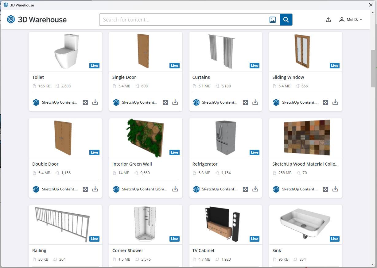
A great feature of SketchUp is the 3D Warehouse, which allows you to search for 3D models made by other users as well as contribute 3D models of your own. It contains 3D models of buildings, cars, interior furnishings and much more. The file sizes can be quite large; however, models can be downloaded straight into the program without saving in your computer’s storage. 3D Warehouse allows anyone to create, modify and re-upload content free of charge! Companies can even have an official page that contains their own 3D catalog of models. The 3D Warehouse offers a wealth of information and can help you design quickly when facing a tough deadline. Best of all, this feature is free!
Figure 1 – Import Options
AutoCAD Architecture 2025
VIEWING A MODEL IN 3D
A camera is used by SketchUp to represent your point of view of the model. Basically, the program treats you as though you are a camera looking at your model as you work. SketchUp uses several tools for viewing your model in 3D space. These are tools that you are familiar with in AutoCAD Architecture – Pan, Orbit, Zoom and Zoom Extents. Each of these tools can be found on the Camera toolbar.
DYNAMIC COMPONENTS
Dynamic Components can be defined as components that have parametrics. For example, a cabinet component has doors that open and close. A component is only considered dynamic when it has parametric data. Dynamic components will display with a special badge when parametric data is present. Attaching attributes to a component is
what makes the component dynamic. Attributes are items such as the component’s name, description, location, size and number of copies. Some attributes are predefined attributes, which means they are automatically available for every dynamic component. There are also custom attributes, which are unique attributes defined by the developer of the dynamic component.
Every attribute of a component has a value that can be a textual string, a number or the result of a formula. Each attribute and its associated value are called an attribute name/value pair. Formulas can consist of predefined functions, mathematical operators or the values of other attributes. Functions are shortcuts that perform an operation such as calculating the square root of a number
It is important to note that all SketchUp users can use dynamic components. However, only SketchUp Pro users can develop dynamic components.
Figure 2 – 3D Warehouse
AutoCAD Architecture 2025
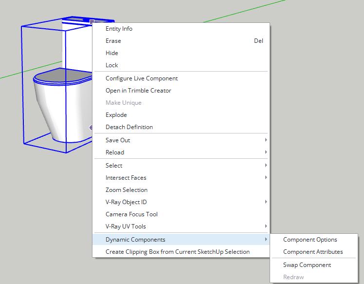
To make a component dynamic, right-click on the component, select Dynamic Components (see Figure 3) and then select Component Attributes. Select Add Attributes and a dialog box will display with attributes that can be added to your component (see Figure 4). Once you have added the desired attributes, the new dynamic component can be saved to a component file for additional use later.
EXPORTING A SKETCHUP FILE INTO AUTOCAD ARCHITECTURE
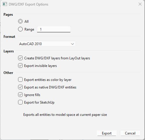
Exporting a SketchUp file into AutoCAD Architecture is easy. Once you are ready to export, select the File menu and select Export. Next select 2D Graphic or 3D Model, depending on the file you are exporting. Select the export file type from the drop-down. Since we are exporting to AutoCAD Architecture, you would select AutoCAD DWG. By selecting the Options button at the bottom, you can choose the AutoCAD version to which you are exporting (see Figure 5). Select Export.
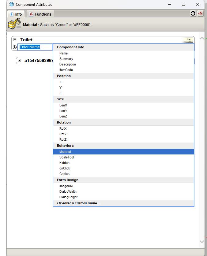
Figure 3 – Dynamic Components
Figure 4 – Component Attributes
AutoCAD Architecture 2025
The exports are now complete! It is important to note that you can alternate between AutoCAD Architecture and SketchUp multiple times. Your drawing does not have to be complete before importing it into SketchUp or from SketchUp into AutoCAD Architecture.
LAYOUT TOOL
Layout and SketchUp Pro are designed to work together. Layout contains many tools to assist you with creating high-quality presentations of your SketchUp models. After inserting a SketchUp model into a Layout document, you can make changes in Layout without having to go back to SketchUp. Just be sure you sync up both your Layout document and your SketchUp file, which allows changes across both. To insert a SketchUp model into a Layout document, select File, Insert from the menu bar in Layout. In the dialog box, find the SketchUp model file, select it and click Open.
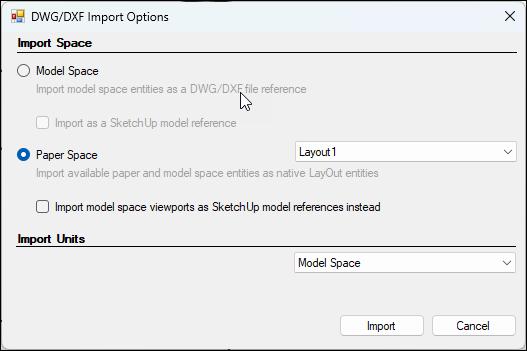
You can even import an AutoCAD Architecture file straight into Layout. To do this, select File, Insert. Select the AutoCAD Architecture file you wish to import and click Open. In the dialog box, select
either paper space or model space, depending on which you are wanting to work with (see Figure 6). Make sure you have everything selected as needed and click Import. You can also export back to AutoCAD Architecture if you wish. This is found under File, Export, DWG/DXF. Navigate to where you are saving the file and give it a name and click Save. Follow the prompts in the dialog box and click Export when finished.
CONCLUSION
SketchUp has many capabilities for great quality presentation drawings. We’ve barely scraped the tip of the iceberg in this article but now it’s your turn. Download the free version, give it a try and see how you like it. There is nothing better than going to a meeting with awesome drawings that took only minutes to complete! Need more SketchUp training? SketchUp’s Getting Started application includes self-paced tutorials that will introduce you to many tools, techniques and procedures.

Melinda Heavrin is a CAD Coordinator & Facility Planner in Louisville, Kentucky. She has been using AutoCAD Architecture since release 2000. Melinda can be reached for comments and questions at melinda.heavrin@ nortonhealthcare.org.
Figure 5 – Export Options
Figure 6 – Layout CAD Import





Geolocation in CAD: A Critical Lesson for Young Civil Engineers

As a young civil engineer, I always wondered why CAD managers emphasized the use of coordinate systems so much. I can’t count how many times they asked me, “Is the drawing geolocated?” I had a general idea of why that mattered, but I don’t think I fully understood the consequences-until a real-world event made it clear.
In 2024, after a major flooding event in Valencia, Spain, a friend living their shared stories of how infrastructure struggled to cope. It reminded me of what I’d seen in Houston during Hurricane Harvey in 2017. I began to imagine a scenario: What if my firm, based in Houston, was awarded a project to support flood mitigation in Valencia? What would I need to do in Civil 3D to prepare for such an international project?
Having never worked outside the U.S., I instinctively tried to set up my design using NAD83 and NAVD88-the standard in the U.S.-but quickly realized they didn’t align properly with maps or terrain in Spain. That led me to discover ETRS89 with UTM Zone 30N, the appropriate coordinate system for the region, along with vertical data provided by Spain’s national mapping agency (IGN).
I thought to myself: What if I had completed the entire design, sent it off for approval, and only then discovered the drawing was misaligned by kilometers because it wasn’t geolocated properly? The risk of wasted effort, budget overruns, and construction delays became very real in my mind.
WHY THIS MATTERS FOR AUTODESK USERS
AutoCAD Civil 3D, Autodesk InfraWorks, and related tools offer robust geolocation features-but only if users activate and configure them correctly. In globally connected workflows, especially through cloud platforms like Autodesk BIM Collaborate Pro, consistent geolocation is crucial for:
• Coordinating across survey, GIS, and engineering teams
• Integrating point clouds, aerial imagery, and terrain models
• Running accurate stormwater analysis and hydraulic simulations - Preventing catastrophic misalignments in large-scale construction
LESSONS LEARNED FOR NEW ENGINEERS
Here’s what I would tell every early-career engineer using Autodesk software:
• Start with a Geolocated Base Map
It might be very tempting but avoid drawing in space. Always begin with verified survey data or public mapping layers with known coordinate systems.
• Use Region-Specific Datums and Units NAD83 (State Plane) and NAVD88 are standard in the U.S. For Europe, ETRS89 and metric units are essential. Double-check what your client or
municipality uses. If you are working in other continents, I will suggest doing your research on their respective standards
• Communicate Coordinate Systems Across Teams
Include projection details in drawing templates and shared documents so remote teams are working from the same reference.
• Practice in Real Projects
Even if you’re just modeling a practice site, try setting it up using real-world coordinate systems. The habit will pay off when it matters.
CONCLUSION
When your CAD manager asks, “Is the drawing geolocated?”-you want to confidently answer, “Yes, and here’s the reference I used.” As a young civil engineer beginning your career, mastering software like AutoCAD Civil 3D is crucial—but equally important is understanding how your design fits into the real world. Geolocation in CAD isn’t a secondary task; it’s a foundational element that ensures accuracy, alignment with GIS data, and effective collaboration across teams and borders. Whether you’re designing a culvert in Texas or modeling a basin in Spain, your design needs to speak the language of its environment.

Isabel Eburi is a Graduate Civil Engineer at Walter P Moore, where she works in the Infrastructure Group. She earned her bachelor’s degree in civil engineering from Texas A&M University. In addition to her engineering work, Isabel is the founder of Entre Estudiantes EG (“Among Students”), an initiative that promotes STEM and STEAM education among students from Equatorial Guinea through mentorship, outreach, and academic programming. She is passionate about leveraging engineering to create inclusive opportunities and drive community impact.
3rd Party Apps

Autodesk Civil 3D has a strong ecosystem of third-party applications that extend its capabilities for civil engineering, surveying, transportation design, and land development. Since there are so many out there, I decided to reach out on LinkedIn and ask for suggestions on some of what you guys use for add-ons. Here’s some of the suggested 3rd Party apps for Civil 3D.
KOBI TOOLKIT FOR CIVIL 3D
Website - https://kobilabs.com/civil-3d/
The Civil 3D Toolkit is broken up into 8 specific areas. Points, Surface & Grading, Alignments, Profiles, Corridors, Pipes, Analysis and Navigation/ Visibility. I’ve looked at all of these and outlined a few of my favorites.
Grading
This powerful grading functionality lets you design various spatial entities with different grading criteria allowing you to save the templates. This is a super helpful tool when it comes to pond/pad grading and setting lot grades in a subdivision.
Kobi Toolkit for Civil 3D
Create Alignment from Feature Line
Create Civil 3D alignment from feature line or 3D polyline element. You can also create a Civil 3D profile if your feature line / 3D polyline has assigned elevations. This is super helpful if you do your initial design using feature lines, as many do. This avoids rework if you ever need to align/profile things after you’ve done your design.
Label Feature Line in Profile View
With this command you label feature lines that were projected in profile view. The issue in Civil 3D right now, is that the grade shows profile grade, not true feature line. This addresses that concern!
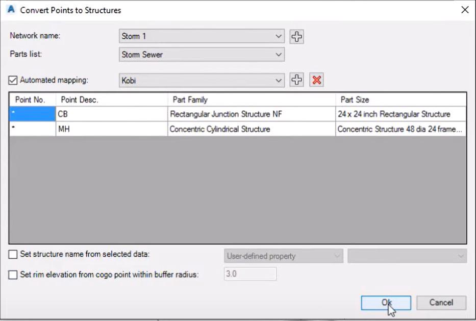
Create Structures from Points
This tool creates pipe network structures from selected COGO points. This is used to automate a pipe network creation process from existing surveyed data.
Level Service Network
This tool allows you to set elevations and grades for all your service (i.e. sewer) lines going into the main without using the structures at connection points.
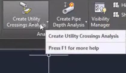
Check Utility Crossings
This tool calculates crossings between utility segments (gravity and pressure network pipes), inserts COGO points at crossing locations and marks crossing elevation difference. Once modifications to your networks are done, there is a simple way to update your utility crossings!
Kobi Signs & Stripes
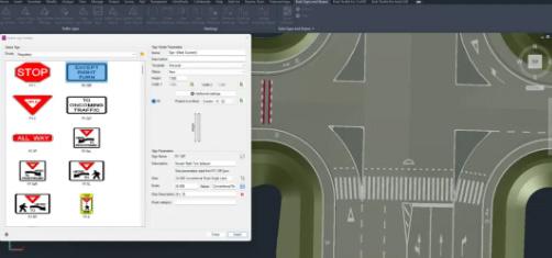
I didn’t know this even existed until now! But Kobi has a really nice set of tools for signing and striping, in both 2D and 3D. There are 2 categories, Traffic Signs & Markings.
The Traffic Signs include commands for inserting traffic signs on polylines or alignments and projecting them onto the TIN surface. You can insert traffic signs in 2D views, section views, and 3D views. Insert a single traffic sign or a group of signs from road databases automatically and edit and/or create traffic sign reports.
The Markings commands allow you to create and edit line markings, cross markings, area markings, and lane markings. You can also label and report on your markings. Enhance productivity by creating custom templates of road markings and using the auto preview option to review changes in real time before confirming them.
TAGIS CAD
Website - https://armavericks. com/tagis-cad/
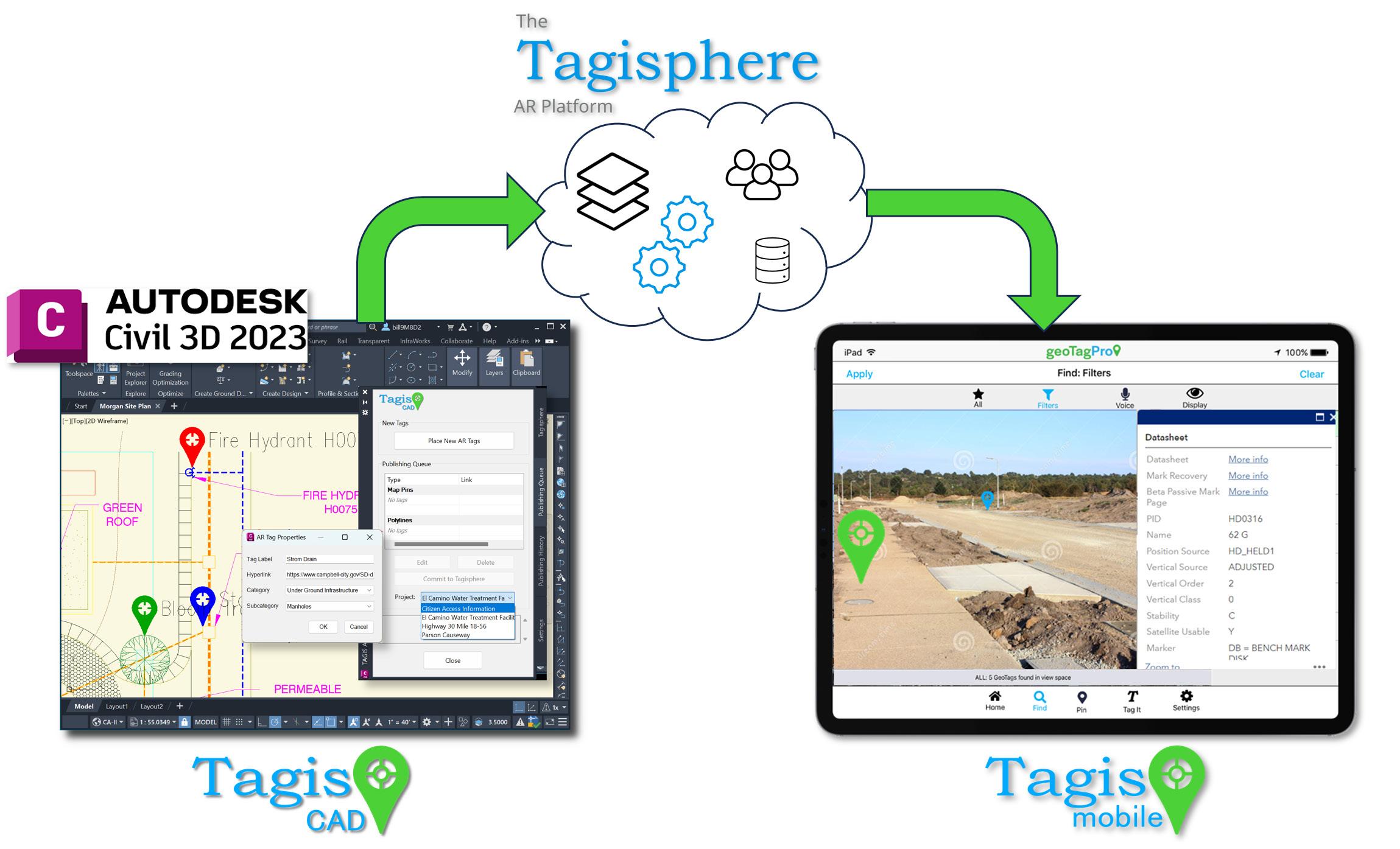
This FREE CAD plug-in for AutoCAD Civil 3D allows you to place geotag blocks in any geolocated drawing.
Tagis CAD allows users to geotag any location in the world from inside an Autodesk® Civil 3D® desktop session. This geotag is published to the Tagisphere(R) cloud server and instantly becomes available as Augmented Reality content in the real world. These geotags show up like a Google Map Pin in the real world. The geotags have a label and can have a hyperlink, allowing a field worker to easily find and instantly access information in the field.
Field users access the data using AR Mavericks iOS app Tagis Mobile. When they start the app, it uses GPS to
Autodesk Civil 3D
determine their geo-location and then contacts the Tagisphere cloud server. The server searches the database for any published geotags that are near their location. The mobile app then shows the user the nearby AR geotags.
Placing geotags is just like placing a block. Geotag blocks utilize color-by-layer, providing a familiar method to control their appearance. A system variable is available to adjust the geotag block size.
Surveyors are typically familiar with *.csv files—a common format for organizing survey points, feature codes, points of interest (POIs), and more... The Tagis Surveyor project tools let you map your point data from a *.csv file into the Tagisphere. The point data can be in any world-based geolocated coordinate system.
Use Cases:
• Flag the locations of hard-to-find underground services such as water meters, irrigation, and electrical vaults.
• Show property corners on undeveloped land.
• Mark locations of maintenance items and links to the maintenance work order
SINCPAC C3D™ SOFTWARE FOR AUTODESK® CIVIL 3D®
Website - https://quuxsoft.com/sincpac/
SincPac is highly regarded as a top tool for enhancing Civil 3D. It’s considered a valuable complement to the software, offering a wide range of commands and features not natively available, addressing many of Civil 3D’s weaknesses and making it more efficient for various tasks.
By providing tools that address Civil 3D’s limitations, SincPac helps users work more efficiently, especially in busy production environments. SincPac adds more than 200 new commands and features to Civil 3D, extending its capabilities beyond the standard tools!!
While it was a bit overwhelming to try and go through every tool, I did and chose a few that would personally help me in my day-to-day workflows!
Offsets for Building Setbacks / Utility Easements
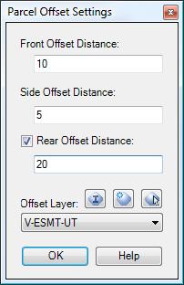
The ParcelOffset command creates offsets with varied distances around parcels. Useful for setbacks and utility easements that run at differing distances around the lot, such as 20’ along the front, 10’ along the sides, and 30’ along the rear.
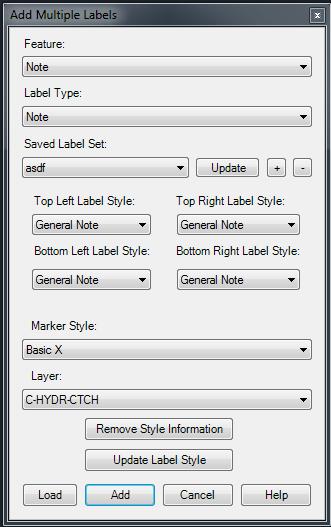
In addition to that, the LotCorners command will points on all lot corners in the selected parcel(s). These 2 combined will save me a ton of time in final plat creation.
Update Point Groups Automatically
The PGUpdateEnabled command enables or disables the automatic updating of Point Groups in the drawing. Why does this not exist in Civil 3D you ask? Great question!!
Point Group Browser
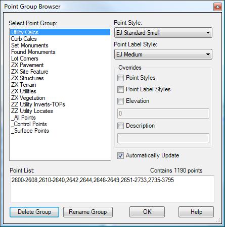
The PGBrowser command provides a quick way to flip through Point Groups and edit the style and override settings. Also displays a Point List of all points currently in the group. The Point List may be edited to add or remove points from the group.
Create Points from Labels
The CreatePointsFromLabels command can be used to create Civil-3D Points at the exact location and elevation of Surface Elevation Labels found in a drawing. This I found to be a huge timesaver for survey stakeout points.
Add Labels in Dragged State
The SPAddLabels command allows the placement of Civil 3D Labels by clicking the anchor point and then the drag location. The style of the label is determined by the styles selected in the dialog box. In addition, the label is placed on the specified layer.
CORRIDOR EZ FOR CIVIL 3D
Website - https://corridorez.com/
I admit, I did NOT download and test this one out for myself……YET! But watching some videos, reading the product breakdown and hearing from MANY people out there, Corridor EZ seems to be an amazing tool for corridor design. The website has a ton of info, so take a look for yourself, but here are a couple key points.
Features Comparison – Native Civil 3D vs Civil 3D Enhanced with Corridor EZ
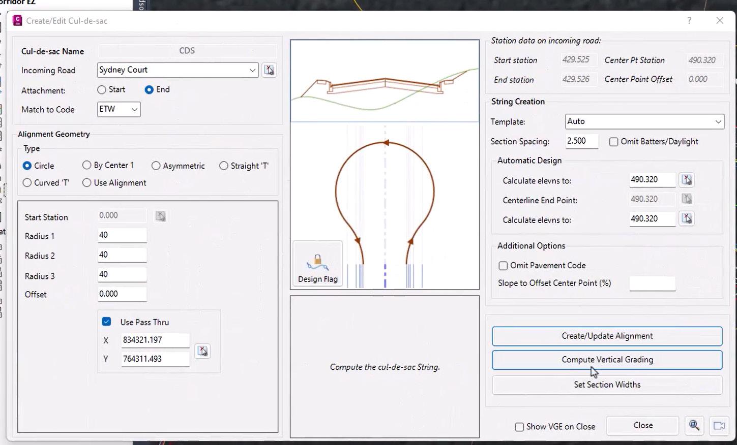
Corridor EZ fills the gaps in Civil 3D, adding preconfigured templates, automatic surface refinement, optimized baseline management, and seamless updates—all while improving accuracy, speed, and usability. Whether you’re working on highways,
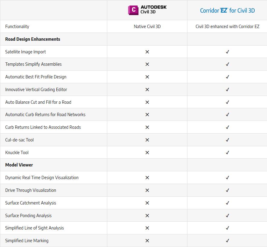
intersections, or site grading, Corridor EZ helps you get the job done faster and with fewer errors.
Project Assist unleashes the power of AI for subdivision road design
Project Assist AI is an integral component of Corridor EZ for Civil 3D, and unleashes the power of AI for subdivision road design by:
• Analyzing your alignments
• Deducing your design intent based on the naming convention used and learning as you make adjustments
• Adding automation to the more complex processes such as widenings, bus bays, parking lots, knuckles and islands
• Allowing new designers to become productive quickly and being able to share designs with senior designers
• Maintaining compatibility with your existing production standards by automatically generating your profiles, surfaces, feature lines and pipe networks

Autodesk Civil 3D
RED TRANSIT
Website - https://redtransitconsultants.com/apps/
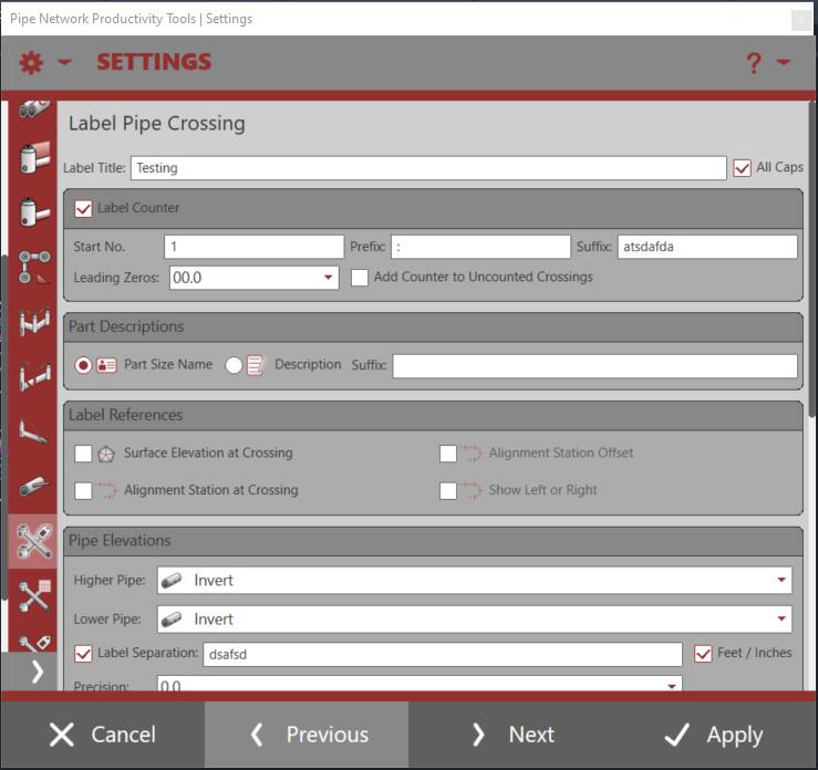
Broken out into several different apps, all downloadable from the Autodesk App store, the tools from Red Transit always amaze me. Their Pipe Network Productivity Tools have set the bar for Civil 3D add-ons for many years, and the Lot Grading Tools are great for anyone doing residential subdivision design. There’s a whole host of other awesome tools to check out as well!
Pipe Network Productivity Tools
They provide increased productivity to the following Pipe Network tasks: Swapping Parts, Adjusting Pipe Elevations, Creating and Managing Service Connections, Modifying Part References/ Descriptions/Styles/Rules/Materials, Labeling Pipe Crossings, Labeling Pipe Elevations at any Point Along Pipe, Renaming Parts, Gathering Quantities, Daylighting Pipe at Surface, and more.
Many of these easy-to-use tools also provide selection capabilities from plan and profile views. Any experienced user of Pipe Networks will immediately recognize the benefits these tools provide.
Lot Grading Tools
The Lot Grading Tool provides tools and settings to assist in the design and grading of a residential subdivision. The Lot Grader command expects that lot lines are Feature Lines with assigned elevations at the right of way established from a road design surface and that pads are four-sided lines, joined as a closed feature line. From here, the lot grader allows for a fence selection across lot lines and pads and will utilize the settings to establish elevations and grades of the lot lines, pads, and the creation of reveal feature line linework offsetting from the pad feature line.
An additional command called the Lot Labeler, allows for labeling multiple feature lines PI points
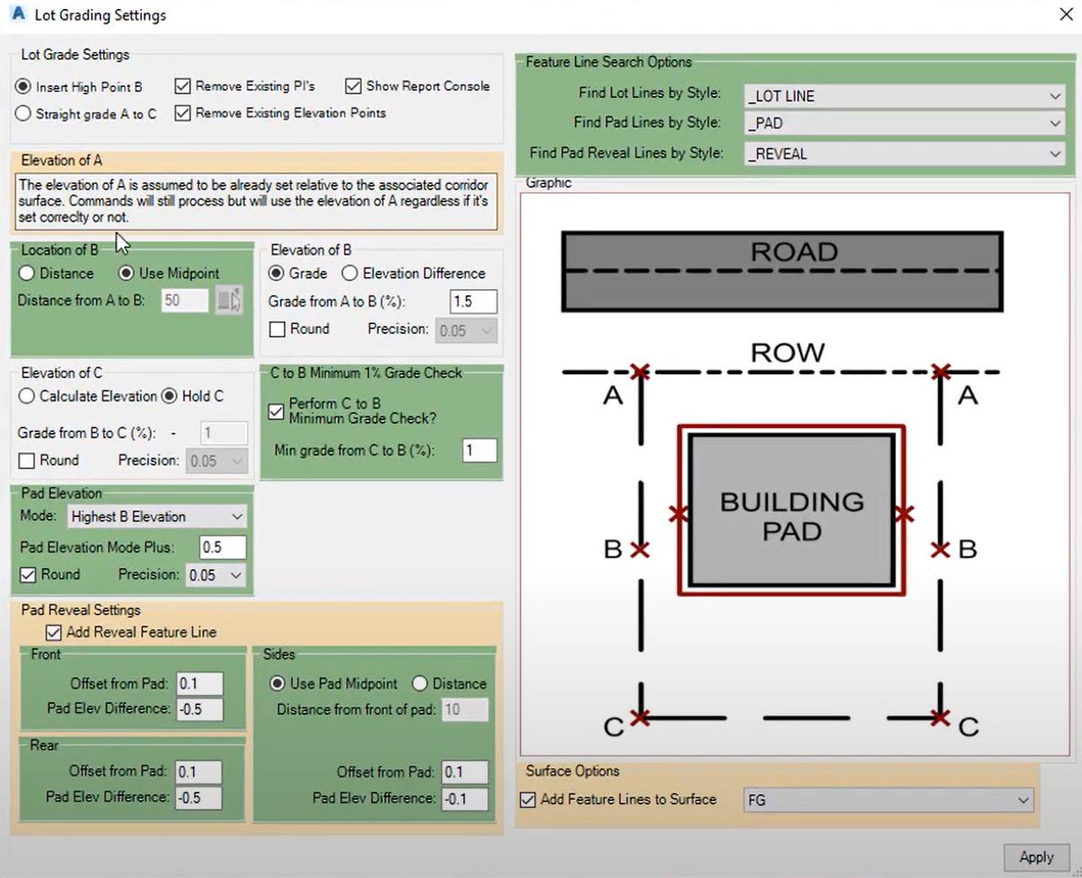

and line slope/grades with desired styles, either in the same drawing or in another drawing containing the same surface. The Lot Labeler allows you to take your grading performed with the Lot Grader to a plan sheet for quickly reviewing the established elevations, slopes/grades across the site.
Check out this video - https://youtu. be/3SZt5twUewg
And finally, here’s a couple more that were suggested by others.
CIVIL SITE DESIGN
Website - https://civilsitedesign.com.au/
Civil Site Design is Australian- made civil engineering software for the design of road, road reconstruction projects, subdivisions, earthworks, drainage and stormwater.
Oh, and check out the Model Viewer they call Design Review! Pretty cool!
CCLS PRODUCTIVITY TOOLS
Website - https://www.civilcadls.com/custom-apps
SPECKLE
Website - https://www.speckle.systems/
CIVIL SITE DESIGN
Website - https://civilsitedesign.com.au/
CONCLUSION
I’m sure there are many, MANY, more add-ons. Some items have been resolved using Project Explorer and later versions of Civil 3D, but there are still a ton of things I wish native Civil 3D would do. Some are wish list items, while some are no brainers that should have been there since day 1. If you have a favorite add-on I’ve missed, or ones you’ve created yourself, feel free to shoot me an email and share what you got!!
Thank you!

Shawn has been a part of the design engineering community for roughly 20 years in all aspects of design, construction and software implementations. He has implemented and trained companies across the Country on Civil 3D and other infrastructure tools and their best practice workflows. Shawn can be reached for comments or questions at sherring@prosoftnet.com.
Save up to 70%


For many businesses, 2D CAD software has become an essential operational tool—but it’s no longer just a productivity expense.
Licensing costs are rising drastically, forcing CFOs, CIOs, and engineering leaders to reevaluate whether their current software aligns with their budgets and business needs.
What if you could achieve the same, or even better, design performance, while cutting your 2D CAD software expenses by up to 70%?
This is the opportunity DraftSight Premium offers.
By using cost-efficient, high-performance 2D CAD tools, organizations can reduce expenses without compromising operational efficiency. Here’s how.
WHY CAD SOFTWARE COSTS ARE RISING
Traditional CAD providers have adopted subscription-only pricing models and named-user licensing, inflating costs for businesses of all sizes. For example, AutoCAD’s subscription model now averages $2,030 annually per license, which is a significant strain on IT budgets managing multiple licenses. Meanwhile, these higher prices don’t always translate into better features or measurable returns, leaving many companies “overpaying” for solutions that no longer meet their needs.
Save up to 70%

BREAKING FREE FROM THE “CAD TAX”
Choosing smarter, more flexible 2D CAD tools, like DraftSight Premium, can free businesses from unnecessary spending. Cost comparisons reveal just how significant the savings can be. DraftSight Premium offers professional-grade CAD solutions at just $599 per license per year. That’s a staggering 70% savings compared to some industry-leading subscriptions.
For teams requiring hundreds of licenses, these savings quickly add up, freeing up capital to invest in other critical priorities, such as R&D, new hires, and tech upgrades.
BEYOND SAVINGS: THE POWER OF DRAFTSIGHT PREMIUM
Cost efficiency is just one of many reasons businesses are making the switch. DraftSight Premium offers robust features that rival, if not surpass, high-cost alternatives. Here are some of the most valuable capabilities teams gain access to:
• Custom Blocks: Reusable components to streamline design workflows.
• STEP Import: Seamless 3D geometry integration across disciplines.
• Sheet Set Manager: Efficient organization for large-scale projects.
• BIM Integration: Simplified hybrid workflows with support for .ifc and Autodesk Revit files.
• DGN Export: Smooth collaboration with external partners requiring specific formats.
Combined with DraftSight’s industry-standard DWG/DXF compatibility and the flexibility of perpetual licensing options, these features make it easier than ever for businesses to meet their design objectives without the financial strain.
GET STARTED TOWARD SMARTER CAD COST MANAGEMENT
Optimizing your organization’s CAD strategy doesn’t have to be complicated. Here’s how you can start saving today with a few actionable steps:
• Custom Blocks: Reusable components to streamline design workflows.
• Explore Flexible Licensing Models: Look for providers like DraftSight that offer perpetual licensing for long-term savings.
• Try DraftSight Premium: Take advantage of the free 30-day trial to see how it fits into your workflows.
• Build a Case for Change: Demonstrate potential savings and reinvestment opportunities to leadership with a clear financial analysis.
TAKE CONTROL OF YOUR CAD BUDGET
Switching to a smarter, more cost-effective 2D CAD solution is no longer just an option; it’s a strategic imperative for staying competitive. With DraftSight Premium, businesses can reduce costs by up to 70% per license while gaining access to the tools they need for high-quality design and efficient workflows.
It’s time to stop overpaying and start planning for a smarter future. Experience the DraftSight difference today with a free 30-day trial.

Revit 3rd party add-insIDEATE Software


This article is about third-party applications for Revit, in particular this article will discuss the features of IDEATE Software Tools for Revit. Some of the tools discussed are specifically used for BIM Model management and others for BIM Model production. We will explore both in this article and explore by example where each of the tools might come in handy for you to use them on your projects.
IDEATE SOFTWARE, WHAT IS IT?
IDEATE Software is a suite of tools specifically designed to help BIM Managers and End Users to simplify and enhance Revit tasks and workflows. Tools like BIMLink helps to enhance data management of Revit Projects that help enable efficient import and export of project data to and from Excel.
We will explore the two different parts of IDEATE Software throughout this article. Part I is mostly
Tools to help managing data often linked to the Revit model but not always linked in a way that the data is live and very time consuming and tedious to keep data up to date.
Another tool in Part I we will discuss further is the IDEATE BIM Explorer tool. These tools help the BIM manager with the everyday quality control tasks to keep models running smoothly for the production team.
Part II of the IDEATE Addins are called IDEATE Apps or tools designed to help the end user to do repetitive tasks more efficiently. Such tasks like Renumbering, Annotate, Spell Check to name just a couple. We will discuss each of these in a little more detail later in the article.
The second set of tools, IDEATE Apps are a set of Revit add-in tools developed to enhance the workflows and give the end user an easier way to access data in the Revit Model. These apps were developed with a specific set of tasks in mind. These tools address challenges that everyone has with out of the box Revit tools (Architecture, MEP and even Structural).
IDEATE SOFTWARE
With IDEATE for Revit installed you will see both the IDEATE Software Tools and the IDEATE Apps Tools in the tool pallet. For any of the tools in the tool pallet that you find yourself using often, you can right-click and them to your Quick Access Toolbar for easy access.
Figure 2 – IDEATE BIM Link
The IDEATE Software Tools are:
• BIM Link – used for sharing data with Excel
• Explorer – BIM Management tools and Browser
• Sticky – Used to link word, Excel and PDF to Revit
• Style Manager – Used to analyze and modify all styles
BIM Link helps you pull large volumes of data from the Revit model and share them with Microsoft Excel and push data back into the Revit Model with speed and accuracy.
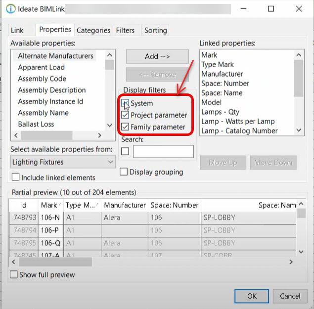
IDEATE BIM Link, allows you to extract data from the Revit model and then manipulate it in Microsoft Excel then push it back to Revit easily and accurately. With IDEATE BIM Link you have the ability to edit System, Project and Family parameters within Revit. Those Parameters can be edited either within a schedule or parameters not easily accessible when creating a Revit schedule. Another feature of BIM Link is that it gives you the ability to Bulk Rename Families and Types within your project rather than using another app outside at the network folder level where your families are stored.
Using BIM Link while looking at a Revit Schedule you can quickly filter parameters in the schedule to look at only the Project Parameters by turning off System and Family Parameters by deselecting the displayed filters. Only properties that display white as seen here in Fig. 2 will be editable in Excel. BIM Link allows you the ability to select properties from other categories and make them available during your exports. Out of the box Revit Schedule filters can only exist as an “And” condition. This means you must satisfy BOTH conditions. BIM Link gives you the ability to un-check the “Elements MUST pass all filters” option which treats these filters as an OR condition.
After exporting data to Excel, it can populate multiple cells by copy / paste method as you’d modify any other excel file.. In Revit before the export, you can right-click and select the Convert Link option which will convert Type Properties so that you can edit those in Excel as well. When you open the Excel file the Type properties will display under a new Tabbed Worksheet in the Excel file. When importing the data back into Revit there are two worksheets to choose from for the data you wish to import back into Revit.
IDEATE BIM Link comes with hundreds of link definitions by default. Under the Samples button on the dialog there are sample schedules based on discipline and workflows that can be loaded and even customized by your organization.
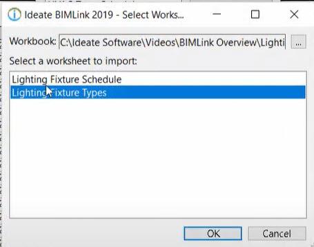
Figure 3 – IDEATE BIM Link – Type Properties
IDEATE Explorer is a file exploration and auditing tool to review elements of your model. The three tabs in IDEATE Explorer are:
• Explorer – True Project Browser
• Navigate – Quickly navigate to model views
• Warnings – Inspect and review model warnings
Unlike the Out of the Box Revit Project Browser, IDEATE Explorer is a True Model Browser that shows every instance of every element that resides in the Revit Model. Depending on your Display settings in the dialog you can look at either a specific selection of items, your active view or the entire model. To further filter down to items you can sort what is displayed in the browser by:
• Category
• Level
• Phase
• Room
• Space Zone
This gives you the ability to drill in on specific things you want to look at in the model as shown here in Fig. 4.
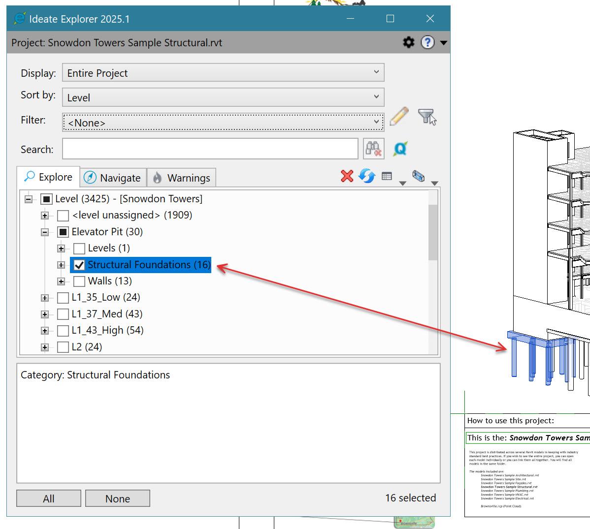
This then gives you the ability to find an element like a specific size door or window in your model and then swap it out with a different size. Doing so in the explorer’s view will quickly replace all the selected size element for the new size throughout the entire project all at the same time instead of finding them, selecting them and switching them. Use the different Display settings to isolate objects in the model that you need to focus on, then you can quickly change the display filters and settings to go back to the original model and move on to the next area of focus. A neat thing about Explorer and the True Project Browser is that it can display cad
links and imported cad data in a model and locate objects that may be hidden in an associated view within said cad import or cad link.
Another IDEATE Explorer tool is the Navigate tab, this tool is quick access to navigate to display views in your project:
• All Views
• Legends
• Schedules
• Sheets
• Views
Figure 4 – IDEATE BIM explorer
By selecting “View”, this will show a list of what views have been placed on a sheet vs the views that still need to be sheeted in the model.
The Last tab of the IDEATE Explorer tool is Warnings. This tool gives you the ability to see the types of warnings found within the model. as well as drilling down to specific elements containing warnings. OOTB Revit doesn’t give the user the ability to dynamically interact with the elements in the warning like IDEATE Explorer does. Warnings can be color coded by the level of severity; you can also isolate elements in the warnings to investigate the issue causing the error. Once the warning has been addressed it is then removed from the list.
IDEATE STICKY
IDEATE Sticky provides live linking of Excel, Word and PDF documents into Revit. When the document changes the linked data in Revit also updates. The path of linked files can be absolute, relative or even stored in the cloud and Sticky will find the linked documents.
IDEATE Sticky can be used to link Excel Schedules or static docs (images), legends or specs to your Revit project. When linking an Excel file to Revit it can be linked either as an Excel Legend or as an image of the schedule (depending on your selection in the IDEATE Sticky dialog).
When linking word documents to Revit you have the control to select which sheets you want to link into Revit. You can select all the pages (default setting), or select individual sheets. After they are linked you can grab the individual sheets and move them around and organize them as you see fit.
When documents are linked to the Revit model you can select the option to Auto-Update. When you save changes to the document the linked Revit model will also update. If you don’t turn this option on you have to select the “Update” button in the Sticky dialog to pick-up and updates to the saved documents. You can control how and when your documents get updated.
STYLE MANAGER
IDEATE Style Manager is a set of tools that help you keep your Revit Projects, Families and Template clean and working smoothly throughout the life of a project. These tools help you analyze the usage of
styles in your project and manage, merge and even delete unused styles.
IDEATE Style Manager helps to streamline the task of identifying non-standard styles within your projects and remove those styles to help keep models running smoothly and efficiently.
IDEATE Style Manager can help you analyze
• Object Styles
• Line Styles
• Line Patterns
• Filled Regions
• Materials
• Filters
• View Templates Text
• Dim Styles
Just to name a few of the items you can analyze in your model.
IDEATE APPS
IDEATE Apps are a collection of tools developed to help the everyday user reduce time spent doing tasks and make them more efficient and streamline their workflow.
One example of such a task is the IDEATE Renumber tool, this tool to renumber a variety of things within your Revit model. Anything from Door or Room numbers to Sheet Detail numbers or even Equipment numbers. The re-numbering tool can automatically renumber elements in your active model as well as linked models.
The re-number tool has pre-defined rules for renumbering elements in your model but also gives the user the ability to create their own custom rules for special project requirements, so it is very flexible to adapt to your needs.
Use the IDEATE Quick Select Tool to easily find, select and even modify elements within your model. Elements such as Lines, Text, View References, Revisions, even CAD Imports. This tool helps you save time navigating through the model to find objects, even those hidden objects that you sometimes have problems finding to resolve an issue.
OOTB Revit doesn’t tell you what you are about to delete when you delete an object from your model. With IDEATE Smart Delete gives you the ability to review the set of objects you are about to delete from the model and help you control what is being deleted from your model. This tool alleviates the accidental deletion of objects that you did not intend to delete from the model and saves you costly time restoring or re-modeling things a second time.
Have you ever seen the error that none of the created elements are visible in a view? How do you trouble shoot that to find said elements? With IDEATE Xray is the tool for you then. Xray checks multiple possible solutions for this warning of objects hidden in views.
Xray helps the team and BIM Managers understand and fix those visibility issues with objects in the model. Having a tool like Xray saves the team valuable time tracking down these issues and allows them to concentrate on bigger issues with the model.
The Revit spellcheck tool is good for analyzing the active view, one downside is that spellcheck does not check the spelling of text in schedules. Ideate Spellcheck lets you check multiple views based on your selections, it checks sheet lists, all schedules and can also generate reports for you to review.
How often are you thrown into a project at the last minute and not familiar with the project setup. The IDEATE SheetManager is your solution. This tool will reduce time spent scrolling and searching for sheets you need to be modified. Use the SheetManager by simply typing in a key word to find the sheet you are tasked to work on quickly and easily. Looking for drafting views that still need to be sheeted, there are 300 sheets in your project but only looking for sheets that start with “A1”, with SheetManager this is all very easy to locate. Your schedules are ALSO searchable through the SheetManager application.
IDEATE SheetManager is developed to expedite sheet layout processes.
Drop multiple views on a sheet all at once
• Move views between sheets more easily
• Control the viewport types
In the background, the SheetManager is working to ensure that the viewport type doesn’t revert to the
default settings for you so you can concentrate on other more important items.
How often do you go to plot a set of drawings and see views that are mis-aligned? The Alignment tool is used to fix alignment of views across many sheets at a time for you.
Have you ever needed to make a copy of a sheet say for a multi floor office building? IDEATE Clone takes care of the manual process of making duplicates of your sheets for you. This tool takes the ten-step process of duplicating a sheet and condenses it into 2 or three steps. This speeds up the process but it also creates better organized looking sheets in the process.
Lastly, IDEATE View Creator automates the timeconsuming process of batch creating views. This tool automates the naming and assigning view property settings. This ensures that views created match your firm’s BIM standards by setting up some batch rules for the View Creator to follow.
In a short time frame, you can take a few views from your starter model or template creating hundreds of views in just a few minutes. This also follows your firm’s standard naming conventions as well as your standard browser organization settings.
In conclusion these tools help with the day-to-day repetitive manual steps and automate them for the project team to be more efficient and allow them to spend more time on the actual design process and reduce the setup time for projects.
IDEATE Software also gives you more tools to ensure your models are kept clean and running smoothly from start to finish of your project.

Kenn Farr is a BIM Specialist at Gresham Smith, he is responsible for training, development and implementation for Structural and Mechanical Engineering for the firm as well as Clash Coordination and optimization of Autodesk BIM software and related applications. He has more than 30 years’ experience in the AEC Industry.


From Chaos to Clarity: Managing Revit Standards with OneNote and SharePoint
INTRODUCTION


In the world of Building Information Modeling, documentation is everything but how we manage that documentation has drastically evolved. Gone are the days of dusty three-ring binders, scattered PDF files, or desktop folders that only one person knows how to navigate. As BIM standards grow more complex and teams become more distributed, the need for a centralized, living knowledge base has become critical.


That’s where OneNote and SharePoint come in.
At Garver, I’ve embraced these Microsoft 365 tools as the backbone of our Revit standards and procedural documentation. OneNote offers a flexible, searchable notebook environment for capturing how-to’s, workflows, and lessons learned. SharePoint brings structure, version control, and easy access for our entire team. Together, they’ve become a powerful system for documenting and evolving our BIM practices which are accessible anytime, anywhere.
WHY ONENOTE + SHAREPOINT?
There are plenty of ways to document BIM standards but most of them fall short when it comes to accessibility, collaboration, and version control. I didn’t want another static PDF buried in a network folder. I needed a living system, something flexible enough to grow with our team and structured enough to keep everything organized.
That’s where the combination of OneNote and SharePoint shines:
• Always Accessible: Whether I’m in the office, at home, or on a job site, I can access our standards from any device. No VPN required.
• Real-Time Collaboration: Multiple team members can view or edit content simultaneously, and changes are automatically saved.
• Searchable Content: OneNote’s search function makes it easy to find a specific standard, procedure, or keyword—even across dozens of pages.
• Structured & Secure: SharePoint allows us to set up permissions, organize notebooks by discipline or topic, and maintain version history.
• Embedded Media: Screenshots, checklists, hyperlinks, even short video clips can all live side-by-side in the same note for clarity and context.
These tools aren’t just placeholders for documentation, they’re dynamic platforms that support continuous improvement, knowledge sharing, and team alignment.
USE CASE EXAMPLES
Standards Repository
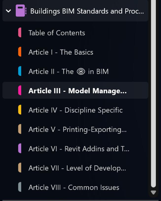
OneNote serves as the central hub for our documented BIM standards. I’ve created a single notebook divided by different sections, like “The Basics” or “The in BIM”. Each section contains clearly labeled pages for the various procedures and workflows. Instead of emailing PDFs or sending people on a treasure hunt through network drives, I just send a link to the right page.

Procedures & How-Tos
From creating a new project in Revit to setting up linked models, procedures are broken into stepby-step instructions in OneNote. These are often supplemented with annotated screenshots or GIFs to make them easy to follow. As processes evolve, the notes get updated with no reprinting required. SharePoint ensures that the most current version is always what’s shared.
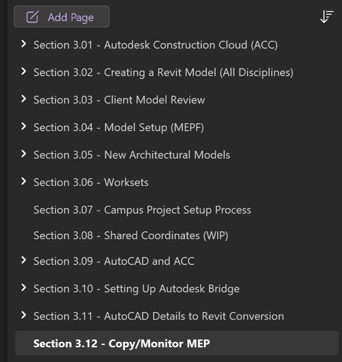
OneNote, surprisingly, does not have a way to create a Table of Contents unless you are doing that manually, which can be quite tedious if there are a lot of pages within your sections. I found a plugin for OneNote called Onetastic that has Table of Contents Macros that you can use to create your own TOC pages very quickly. For a small fee, I think it is well worth it.
Team Feedback & Continuous Improvement
A new Microsoft Form will be introduced to allow the design staff to provide feedback on current processes, procedures, and workflows, as well as to propose ideas for new ones. This form will feature categories tailored to specific aspects of project workflows, such as BIM standards, software usage, and team coordination. Responses will be automatically collected and organized into actionable data sets, helping me prioritize updates and improvements. Furthermore, periodic reviews
OneNote & Sharepoint
of feedback will ensure that the evolving needs of the team are met efficiently.
FOLDER STRUCTURE AND PERMISSIONS
Resources Folder Hierarchy
In SharePoint, I’ve created a BIM Standards site called “Buildings BIM” with clearly named resource folders for various categories:
• BBL BIM Standards
• 3rd Party Add-ins Meet the Team
• AUGIWORLD
• Training
Each folder contains relevant files; PDFs, excel, word, photos, etc. pertaining to the title of the folder.
Permission Management
SharePoint allows me to control access at both the library and page level. For example:
• BIM team leaders have edit access to notebooks, but I am the only one that edits and creates new pages.

• Our Design staff have view-only access to finalized standards.
• I personally do not use this, but you could have a separate “Working Drafts” section allows for collaboration before anything is published to the official standards.
This setup prevents accidental edits while still empowering the team to contribute ideas and improvements through designated channels.
Version Control and History
Every time a change is made in OneNote, or a file is updated in SharePoint, it’s logged. If something ever goes sideways, I can easily revert to an earlier version. This has saved us more than once when edits were made in haste or confusion.
Figure 2 - Current Sections of Article III: Model Management
Figure 3 - Onetastic TOC Macros
LESSONS LEARNED
Start Simple and Evolve
It’s easy to over-engineer documentation. At first, I tried to set everything up perfectly with too many sections, nested pages, and color codes. In the end, simplicity won out. Clear labeling and intuitive navigation mattered more than polished formatting. When I initially began creating documentation, I utilized Microsoft Word. The document rapidly expanded to over 200 pages. Updating the table of contents and ensuring all pages were current each time new sections were added or existing ones expanded proved to be quite challenging. Subsequently, I transitioned to using OneNote, which better accommodated my dynamic requirements.
Involve the Team Early
Documentation doesn’t live in a vacuum. I learned that if people don’t feel like they have a stake in it, they won’t use it. By involving power users and project leads in the structure and content review, I saw a huge jump in engagement and adoption. Regular workshops or feedback sessions became an integral part of the process, where team members could share their insights, propose updates, and identify gaps in real time. This participatory approach not only improved the documentation but also fostered a sense of ownership and collaboration across the team. Furthermore, gathering input from different disciplines ensured the documentation was comprehensive and addressed practical needs from multiple perspectives.
Link, Don’t Duplicate
Rather than storing the same content in multiple places, I’ve leaned on linking between OneNote and SharePoint. If there’s a reference file that supports a procedure, I link to its location in SharePoint. Additionally, cross-linking between different OneNote pages enhances navigation and provides context for users, making it easier to connect related topics and access relevant information without redundancy.
Make Maintenance a Habit
Maintaining documentation is far from a “set it and forget it” task. It requires a deliberate and ongoing commitment to ensure it remains accurate, relevant, and practical for its users. To achieve this, I have implemented a structured review process where
key sections are revisited periodically—admittedly, this doesn’t happen as often as it should. During these reviews, I assessed whether the content aligns with current workflows, standards, and project requirements, making updates as needed.
Additionally, I actively encourage team participation in maintaining the documentation. Team members are invited to submit updates, corrections, or suggestions as part of our regular BIM standards improvement loop. This collaborative approach not only keeps the information fresh but also fosters a greater sense of ownership among users. The team is more likely to engage with and rely on the documentation when they see their contributions reflected in it.
It’s important to emphasize that perfection is not the goal; rather, progress and relevance are what truly matter. Each update, no matter how small, contributes to the documentation’s overall utility and ensures that it continues to serve as a vital resource for the team. By treating maintenance as an integral part of our workflow, I’ve found that the documentation evolves organically, keeping pace with the dynamic nature of our projects and standards.
Promote It Like a Product
Developing documentation isn’t enough; it requires active promotion and integration into daily workflows to ensure its usefulness and adoption. I treat our documentation system like an internal product by regularly showcasing its features and updates in the Buildings BIM Bulletin, during project kickoff meetings, and even in team huddles. For instance, I highlight new pages, demonstrate improvements, and encourage feedback loops. During onboarding or training sessions, I integrate short demos to familiarize new team members with the structure and navigation of the documentation system. This proactive approach not only maintains visibility but also reinforces its value as a critical resource for the entire team, driving both engagement and consistency in its use.
PRO TIPS & ENHANCEMENTS
Embed Visuals for Clarity
A good screenshot can save a hundred words. I embed annotated Revit screenshots or short screen recordings (using SnagIt or Stream) directly in OneNote pages.
OneNote & Sharepoint
Cross-Link Pages for Context
OneNote allows internal linking between pages and sections. I use this to connect related procedures, standards, and resources. For example, a Revit view naming standard might be linked to the sheet naming guide and a related example project.
Use Tags for Fast Retrieval
Tags like “To Review,” “Key Standard,” or “Draft” help me, and the team quickly filter and prioritize notes. Searching by tag is especially helpful during audits or standards updates.
Pin Key Pages in SharePoint
You can pin notebooks or files to the top of any SharePoint library. I use this for our BIM Start Here page, a launchpad to common resources, templates, and the latest updates. I also have direct links to OneNote pages for Discipline specific workflows.
Create Quick Access Shortcuts
Adding SharePoint notebook links to Teams tabs or Outlook bookmarks puts documentation a click away from everyday tools. If it’s easy to reach, people are more likely to use it. We are working on a Buildings BIM Toolbar for Revit so that users can access the documentation much faster.
Turn
Feedback into Action
I include a simple “Feedback” or “Suggest an Edit” page in each OneNote section. This keeps the door open for improvement and builds trust that documentation isn’t locked behind gatekeepers.
CONCLUSION
Documentation doesn’t have to be a dusty relic, or a forgotten PDF buried on a shared drive. With the right tools and a little intentional structure, it can become a living, breathing part of your BIM workflow, accessible, adaptable, and actively used.
For me, OneNote and SharePoint have become more than just apps, they’ve become the framework for how I build, share, and maintain Revit standards and procedures across our teams. They allow us to move faster, stay aligned, and continuously improve without starting from scratch every time.
Whether you’re just getting started or looking to overhaul how your standards are managed, I
encourage you to look beyond traditional methods. Create something searchable. Something collaborative. Something that works with your team, not against it.
It’s not about being flashy, it’s about being functional, and that’s exactly what this system delivers.

Jason Peckovitch is an Autodesk Revit Certified Professional for Mechanical and Electrical Design located in SE Iowa. He is a BIM Manager for Garver’s Buildings Business Line, specifically MEPF. Garver has more than 50 offices across the United States and more than 1300 employees. His CAD/BIM career spans over 25 years, and he transitioned to the AEC Industry in 2007 as a Mechanical HVAC Drafter before moving into BIM Management, where he has been working since. Jason is also the father of three children; Shelby – 13, Blake – 10 and Logan - 7, a published photographer, gamer, and car/tech guy. He can be reached at jmpeckovitch@ garverusa.com, found on X under the handle ThatBIMGuy, or connect with him on LinkedIn or several other user platforms like AUGI Community, CAD Manager’s School or BIM Heroes.

Our ElectroBIM software integrates single-line diagram generation, customizable panel schedules, automatic feeder and breaker sizing, voltage drop calculations, circuiting tools, and load calculations directly into Revit. The software embeds all electrical data within the Revit model, streamlining documentation accuracy and aligning with electrical drafting standards
Click to learn more about Design Master’s ElectroBIM for Revit.

AUGI Members Reach Higher with Expanded Benefits
AUGI is introducing three new Membership levels that will bring you more benefits than ever before. Each level will bring you more content and expertise to share with fellow members, plus provide an expanded, more interactive website, publication access, and much more!
Basic members have access to:
• Forums
• HotNews (last 12 months)
• AUGIWorld (last 12 months)
DUES: Free
Premier members have access to:
• Forums
• HotNews (last 24 months)
• AUGIWorld (last 24 months)
DUES: $25
Professional members have access to:
• Forums
• HotNews (full access)
• AUGIWorld (full access and in print)
• ADN 2013 Standard Membership Offer
DUES: $100

Master Shortcuts And Boost Your Productivity
Two weeks ago, I found myself in a classic student panic, my Civil3D project was due in two days… and I hadn’t even started. All I knew was I had to finish it, and it had to be good. Fast.
So, I rolled up my sleeves, cracked my knuckles, and dived in. Five minutes in, I realized this project isn’t hard because it’s complicated. It’s hard because Civil3D is making me do the same tasks repeatedly. Click here, adjust that, rename this... rinse and repeat. It was like trying to build a skyscraper with a spoon.
I later discovered that Civil3D has a bunch of tools and settings designed to make your life easier. I started by customizing my workspace to fit how I work, finding built-in tools that do half the job for you, and even playing with some automation to skip the repetitive stuff. Suddenly, I wasn’t just racing the clock, I was beating it. If you’ve ever found yourself stuck in an Autodesk project, don’t wait until the last minute to figure things out like I did.
Let’s discover why using the default setup in CAD can slow you down, simple ways to work faster in Autodesk software and the effectiveness of customizing your workspace.
WHY STICKING WITH THE DEFAULT SETUP IN CAD CAN SLOW YOU DOWN
If you’ve ever felt like you’re spending more time clicking around than designing, you’re not alone.
Here are a few common problems that come with using CAD software right out of the box and how they can slow you down:
1. Doing the Same Thing Over and Over
You might find yourself constantly setting the same layers, adding the same notes, or drawing similar shapes again and again. It gets tiring and wastes time. Customizing your tools can help speed that up.
2. Shortcuts That are not your Style
CAD programs come with default keyboard shortcuts, but they might not feel natural to you. If you’re constantly jumping between tools and menus, it can break your flow. Creating your own shortcuts can really help.
3. Missing Out on Automation Tools
There are powerful tools like AutoLISP (in AutoCAD) and Dynamo (in Revit) that can automate repetitive tasks. The problem? Most users don’t know if they exist or aren’t sure how to use them. Learning just a little about these can save you tons of time.
4. Too Much Menu Hopping
Trying to find a rarely used tool can feel like a treasure hunt through menus and tabs. It slows everything down. Organizing your workspace or using the search function can make things much faster.
SIMPLE WAYS TO WORK FASTER IN AUTODESK SOFTWARE
If you find yourself endlessly clicking through menus or repeating the same tasks in AutoCAD or
Revit, there are plenty of things you can do to make your workflow faster and easier. Here’s how:
1. Set Up Your Own Keyboard Shortcuts
Instead of using the default commands, replace them with your own shortcuts that are easier to remember.
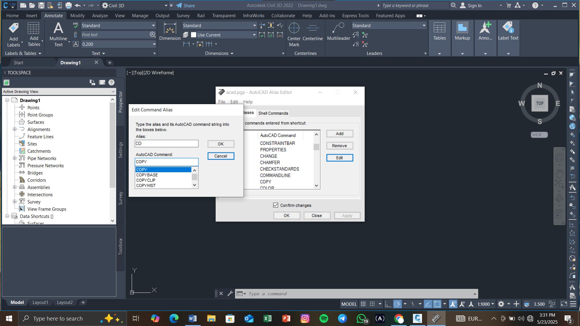
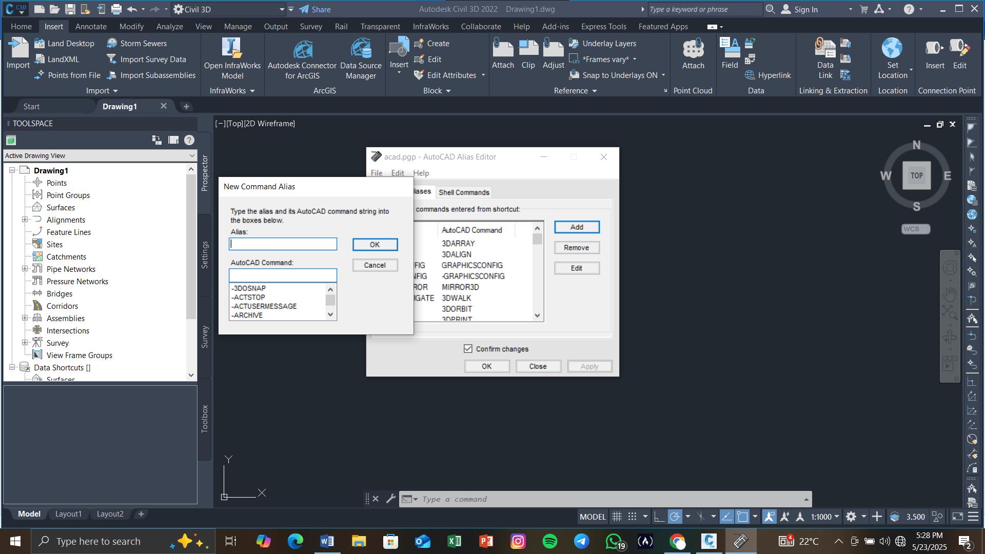
In AutoCAD: Use the Command Alias Editor (ALIASEDIT) to create simple shortcuts.
In Revit: Go to the Keyboard Shortcuts settings under the “View” tab and set them how you like.
Example:
Instead of typing CO for “Copy,” you could just use C. Or, in Revit, you could set “Section View” to the S key.
2. Create a Custom Tool Setup
Having your favorite tools ready to go saves a lot of time.
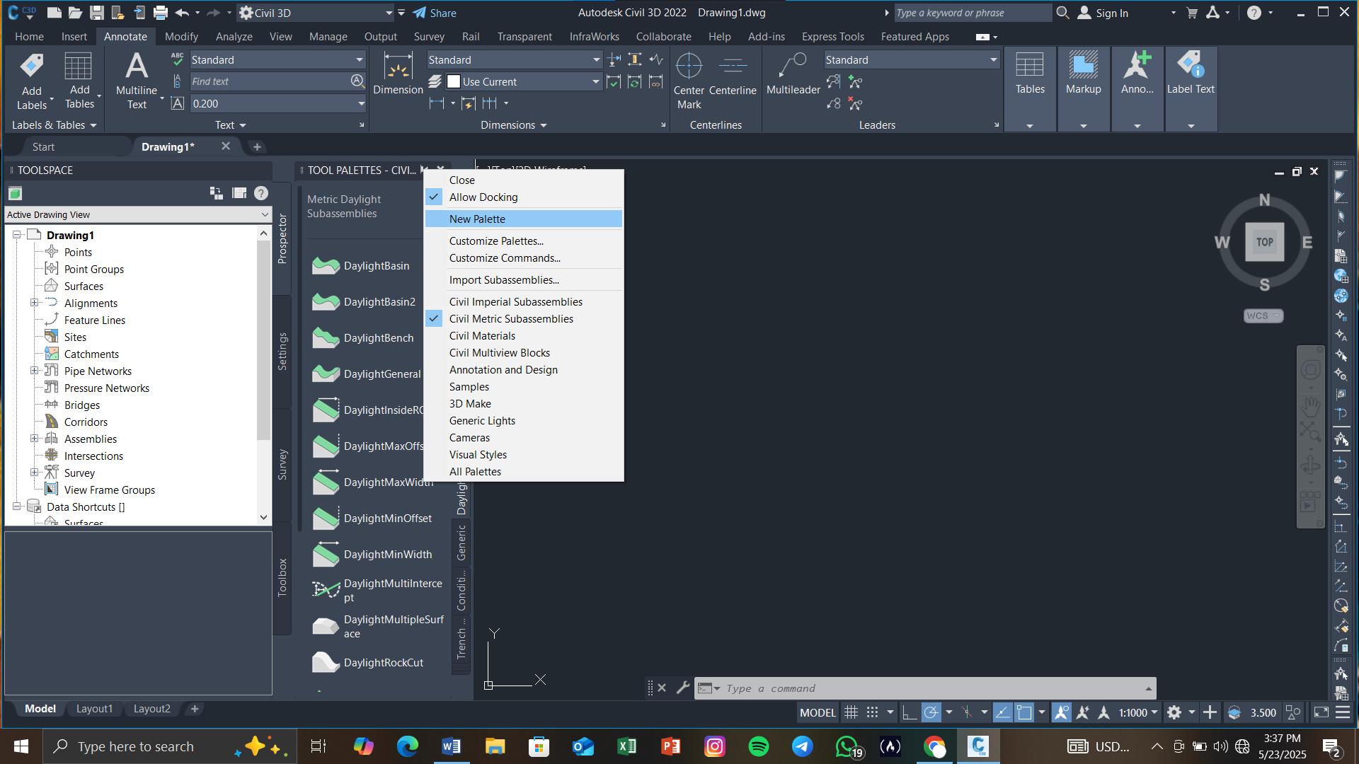
AutoCAD: Make a tool palette with your most-used blocks, hatches, or scripts.
Revit: Rearrange your ribbon so the tools you use most are always visible. Why it helps: You won’t have to dig through menus every time you need something.
3. Automate Repetitive Tasks
If you keep doing the same things over and over, let the software do it for you.
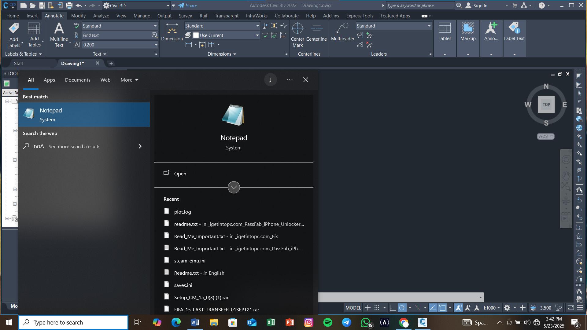
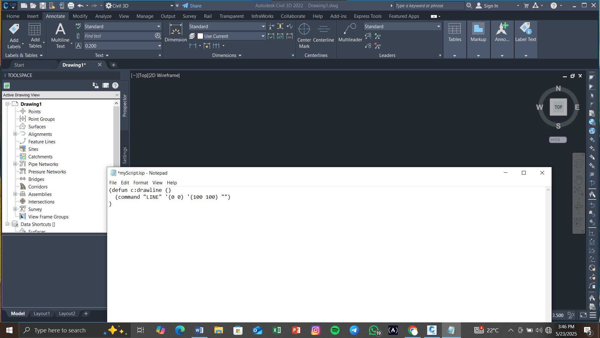
In AutoCAD: Use AutoLISP scripts or simple macros to automate tasks like placing blocks or renaming layers. AutoLISP scripts usually end with the .lsp file extension. You can create one using Notepad or any text editor.
Just save it with a .lsp extension (for example: myScript.lsp).
Here’s a tiny example script that just draws a line: lisp (defun c:drawline () (command “LINE” ‘(0 0) ‘(100 100) “”) )
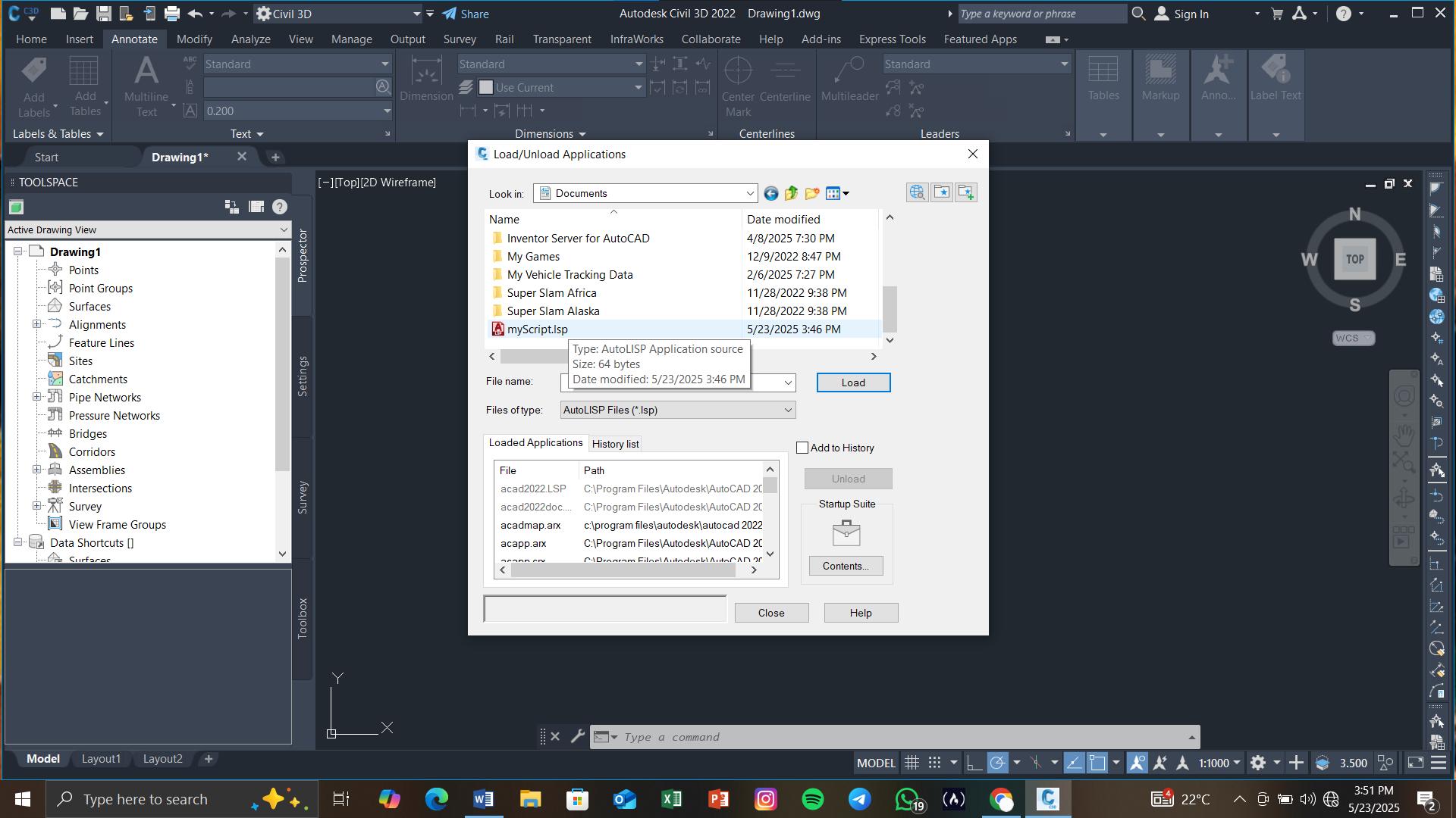
This defines a custom command called drawline. Load the Script into AutoCAD. There are two common ways to do this:
Option A: Using APPLOAD
1. In AutoCAD, type APPLOAD and press Enter.
2. In the dialog box, find and select your .lsp file.
3. Click Load, then Close.
Option B: Drag and Drop
1. Open your Windows File Explorer.
2. Drag your .lsp file directly into the AutoCAD drawing area.
3. It’ll load automatically.
Run the Script. Once it’s loaded, just type the name of the command you defined in the script. For the example above, you’d type DRAWLINE, and press Enter.
In Revit: Use Dynamo, a visual scripting tool, to automate things like renaming multiple views or generating sheets.
You don’t have to be a coding expert to use AutoLISP scripts and Dynamo, there are plenty of examples online to get you started.
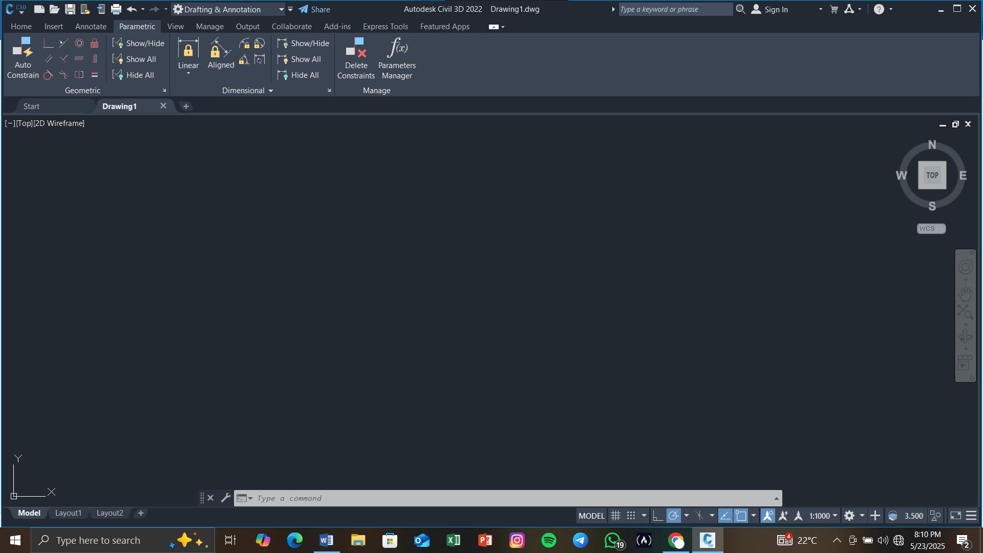
4. Use Templates to Start Projects Faster
Don’t start from scratch every time. Use templates with your settings already in place.
In AutoCAD, set up a template with the layers, styles, and settings you always use.
In Revit, build templates with your standard sheets, schedules, and view styles.
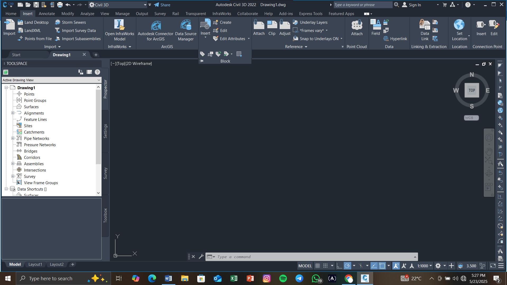
Bonus: It helps your team stay consistent too.
5. Use Aliases for Quicker Typing
Think of aliases as nicknames for commands.
In AutoCAD, you can edit a file called acad.pgp to create your own aliases. This means you can type just “L” for LINE, or something short like SP for a viewport scale command.
It might take a few minutes to set up, but it can save you hours later.
Try Out Built-in Tools You Might Be Missing
Some powerful tools are already built in you just need to use them.
In Revit, tools like Align (AL), Tag by Category, and Filters can speed up drawing and organizing.
In AutoCAD, dynamic blocks and parametric tools give you more control and save time.
CONCLUSION
Making your workflow smoother does more than just save time:
You work faster because you’re not repeating yourself.
You make fewer mistakes because things are automated.
Your team stays consistent because everyone uses the same setup.
You stay focused because you’re not constantly breaking your flow.

Jesse Festo is a Civil Engineering undergraduate at Multimedia University of Kenya. He is a student member of the Chartered Institute of Building.
From Quote to ActivationDigital Twin for Hyperscalers Streamlining Connectivity with SpatialNET and BricsCAD®

Hyperscalers build the world’s largest and most advanced networks, and there is a never-ending demand for more bandwidth and services. Designing and operating hyperscale networks requires collaboration among engineering firms, techs, vendors, ISPs, and Data Center operators. For cloud users, deploying world-class server infrastructure at the click of a button has been a game-changer in time and cost savings. But for Hyperscalers, managing and scaling the complex network infrastructure isn’t quite so simple.
Behind the scenes, AI, Data Center automation and Cloud Computing all require carefully planned maintenance and management strategies.
Efficiency, scale and performance are key to landing enterprise and government contracts. Achieving the performance and availability demands requires sophisticated tools to help the different teams and contractors collaborate on enablement and onboarding, maintenance, and operation.
Traditionally, many of the specialized tools in use by these teams have been operated in isolation, contributing to information silos. This article focuses on the critical role played by physical network inventory Digital Twins to manage the hardware, cabling and connectivity in these vast Data Centers and information super-highways. Highquality, accurate data in the Digital Twin dissolves information silos, allowing seamless cross-vendor
collaboration and even AI agentic integration. Tools that share data, are easy to understand, and quick to update help Operations teams ensure the smooth continued operation of these virtual worlds.
Of course, today’s AI landscape also demands rapid deployment of new networks and services. Network augmentation must meet redundancy and capacity standards, often necessitating permits even for nearby POPs. Network documentation for as built and planned stages is often fragmented and dispersed between contractors, delaying delivery, and in some cases preventing the vital information from being loaded back into the system of record. This exposes a unique challenge, meeting the immediate demands of rapid network and user expansion, while managing long-term deployment phases that require planning and construction.
Systems like spatialNET powered by BricsCAD® manage the Digital Twins with visibility, version control, and automations to assist with the build and operation processes. Let’s take a deeper dive into some details from a simple use case.
➥ Case Study: Enterprise Customer seeks dedicated connection to Private AI Offering
In this scenario we will explore some of the steps that happen when an enterprise customer requests a dedicated connection to a private AI offering in a secure Data Center. The scale of this order requires infrastructure augmentation and new cable routing to link into the existing systems, as well as
diverse customer lead-in cables, to ensure the new dedicated service is maintained.
Let’s look at ways in which an engineering solution and the physical network Digital Twin can assist planning and delivery of a seamless service activation in this scenario.
1. INITIAL SALES CONTACTED FOR A QUOTE FOR A HIGH-LEVEL DESIGN
An Account Executive needs to deliver a quote to the prospect quickly and accurately to start the customer experience on the right foot. Using SpatialNetworX spatialDESIGNER an easy-to-use automated route finding and design tool, quickly generates a ‘proposed high-level’ plan, including details such as:
• whether the customer site is inside a vendor footprint or near a POP,
• and the estimated costs for the construction elements of needed.
• options for numbers of fibers to reserve, and if an alternate diverse path is required, and ability to configure and set rules to make this work for your custom SLA, RFP or costing requirements.
The high-level plan consists of the lead-in cables and support infrastructure (new and existing)
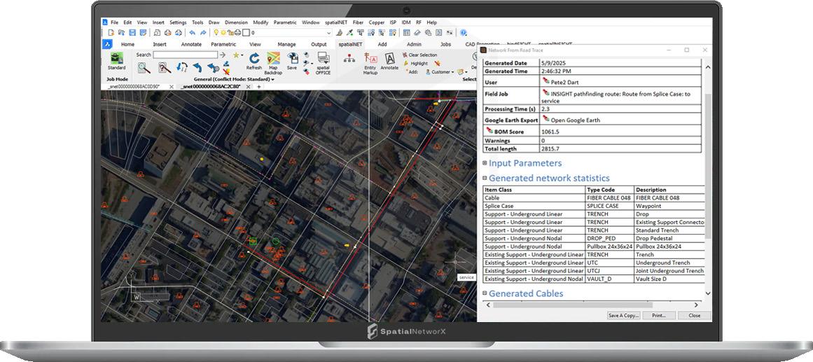
that is required to get to the customer site from the closest access point, as well routing, splicing and reserving fibers and ports within the existing network all the way back to the Data Center. (See Fig. 1 - Example of a High-level plan built with an automated route for the prospective customer.)
The high-level plan can cycle through several iterations, aimed at providing visibility, promoting collaboration, and avoiding redrafting where possible. The typical cycle has three stages;
• Initial auto-generated high-level plan with estimated costs.
• The review and refine process using high-level design revision.
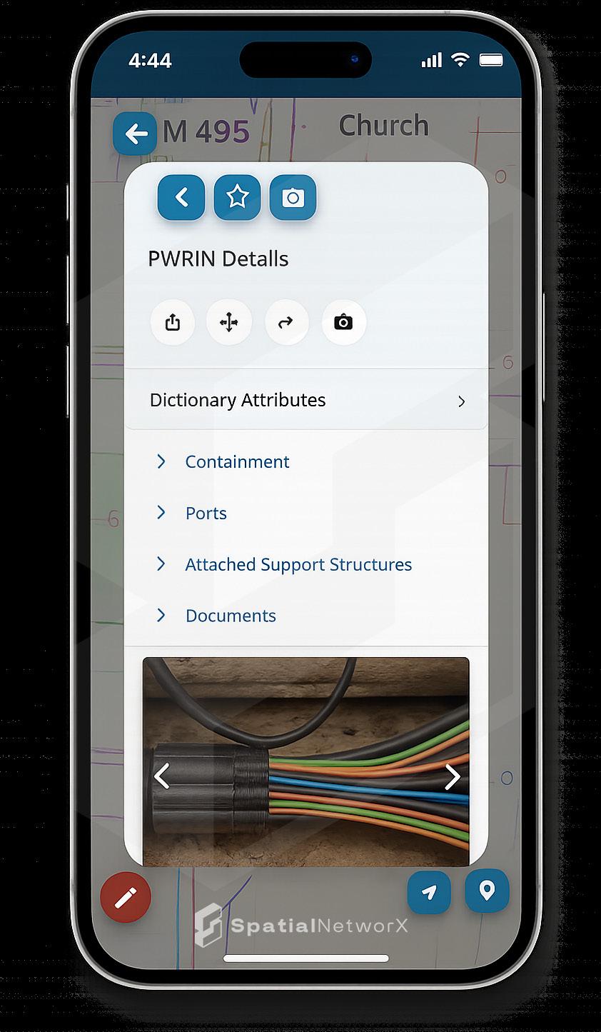
• Transition or ‘Promotion’ of the high-level plan to a fully detailed and version controlled low level design, including post processing with drafting adjustments, construction notes and work print generation with title blocks and templates.
For the initial high-level serviceability in some simple cases the whole process can be automated to deliver a quick yes / no and a quote behind a website request.
Once the quote has been provided to the customer the reservations will hold the fibers and ports for a configurable period of time.
2. QUOTE ACCEPTED! NOW TO ‘REVIEW, REFINE AND BUILD’
Inevitably there will be revisions on any plan.
The Hyperscaler will want to view the high-level plan in GIS formats such as KMZ and analyse the proposed route(s) with overlays such as Satellite images as depicted in Figure 1, visualization tools like Streetview, and many more. These backdrops help to refine design elements and support cost decisions. If modifications are required, spatialNET can easily transition to editing mode compatible with normal CAD tools, or our spatialDESIGNER can regenerate the plan with custom criteria to intelligently design around the issues.
SpatialNetworX spatialFIELD app provides access to the vital network data views, schematics and asset details from the back pocket of every field technician. It is able to view a future network state, enabling a site survey to capture redline comments, images and link them back to the proposed highlevel design. (See Fig. 2 - capturing some images in spatialFIELD for ‘Site Survey’ during a walk out with the high-level plans.)
The circuit design, capacity, bandwidth, and networking configuration will be performed in other DCIM systems, which can be easily modelled back into spatialNET with our API and support for updates and use of custom fields. SpatialNET comes back into play to model the racks, splicing, patching, termination panels and network gear required as part of this order. SpatialNET’s exclusive capability is linking the external infrastructure (OSP) to internal systems (ISP) and integrating all OSS/ BSS info related to the same order. The full value of this capability shows in the themed floorplan views

which allow the NOC engineers to quickly search for free space within existing racks. Reserving space in a rack for a new patch panel or switching device is just as easy as adding the reservation to the external fiber. SpatialNET automatically links the internal rack space reservation to the order, shows a complete trace of the reserved circuit from the conduit outside to the rack inside the DC. (See Fig. 3 - SpatialNetworX ISP view showing chassis, cards with XFP port modifiers and associated floorplan.)
3. TIME FOR THE DETAILED ENGINEERING WORK PRINTS, LOW-LEVEL DESIGNS FOR OSP AND ISP
The process of promoting a high-level to a lowlevel design is a simple automated process, but behind the scenes we are converting a simple CAD polyline into a complex model of a fiber cable, with auto-naming, splicing details, lengths, storage loops, splice trays, port termination details and associations to support structures along the way.
In less than 3 minutes, we have the beginnings of the construction drawings, splice reports and engineering detail that is required for any civil works. Here each detailed measurement - including curb offsets required attribution, and construction notes - can be added and generated.
The construction and commissioning work may take a while but having the reservations and a unified view speeds up communication,
approvals and ensures that systems are ready to go when the physical connections have been built. Where the job involves construction, permits, physical plant updates there will be a requirement for construction drawings. We may be moving towards the paperless world, but many construction jobs still require CAD drawings. Detailed maps with dimensions, work print, call outs, and construction notes can be effortlessly produced by spatialNET (See Fig. 4 – Automated map construction drawing example.)
During the build phase sharing the plans with engineers and construction teams is critical. Collecting the as-builts and updating the Digital Twin records is the vital step that can be easily overlooked. SpatialSUITE provides the tools set to share this model not only as CAD and drawing files but as connected network data into the downstream OSS and BSS systems. Live updates for as-built can be fed back either by APIs from other construction tools or with spatialFIELD from the smart phone.
4. ORDER FULFILMENT, ONGOING MAINTENANCE AND OPERATION
The ways in which these systems can be fully integrated with field construction tools and assist in provisioning is the subject of a future article. From the perspective of the operational records and the Digital Twin the key part is that design corrections and as-built information flow back into the system.
Figvure 3
BricsCAD
Once the design, planning, and revisions are complete, the order is fulfilled. The status of the planned circuit moves to ‘Inservice’, so all tools see this as a live circuit.
Once the service is operational, this accurate data within the platform continues to be of great value to the whole enterprise. There’s a contract with a detailed availability SLA in place, capacity planning and management requirements, and utilization reporting and billing management requirements. Having an up-to-date Digital Twin that covers the network from inside to outside, means all the information is in one place to quickly resolve issues, make informed business decisions, and plan for growth.
SpatialNET provides all the physical details for a logical circuit, with lengths, connections, support structures, latitudes, longitudes, and estimated losses from an outage. This can all be integrated with the live monitoring systems and called up when required.
CONCLUSION
The different tools used by vendors, contractors, and others require multiple layers of management just to integrate. SpatialNetworX solves this by allowing everyone to collaborate, no matter what tool or platform they use. This includes:
• ISPs who work primarily with GIS, Engineering firms who use CAD.
• Field techs with mobile devices, NOC engineers with DCIM needs, Sales teams needing OSS/BSS.
• BI tools, data lakes, and even AI can be integrated with our seamless API and ETL compatibility.
Getting accurate records to all these teams and tools means everyone is on the same page. Adding in the ability to design, revise, and plan for the future from a physical engineering perspective allows these teams to collaborate and provide the seamless experience their customers expect.
SpatialNetworX spatialNET - Industry-leading network design and maintenance tools give power and control to the people who plan and design networks. The system provides seamless network modelling for all OS and ISP fiber, coax and copper network architectures. spatialNET is the tool of
choice for some of the largest network operators in the world. spatialNET running on BricsCAD is native dwg, 100% compatible DWG files along with other industry standard data formats.
spatialNET demonstrates the power and flexibility of seamlessly integrating best-in-class commercials like BricsCAD® in advanced fiber planning and design applications.
Whether you’re expanding a network or modernizing legacy systems, spatialNET delivers the tools you need to stay ahead in a competitive market. Don’t just design—design smarter. Explore spatialNET powered by BricsCAD today and see how it can transform your telecom projects. Find out more about SpatialNetworX capabilities here: (LinkedIn_SpatialNetworX - Data Centers, OSP Activity)
MORE ABOUT BRICSCAD®
Bricsys® BricsCAD® from Bricsys®, part of Hexagon, is professional CAD software without compromise. Accelerate your time to deliverable without compromising on performance, cost, licensing flexibility, and data security. Not ready to buy? Download the free, 30-day trial of BricsCAD® at Bricsys.com. Would you like free lessons? We have that available with Bricsys Learning. Ready to migrate to BricsCAD®? Download the Migration Guide. The latest version of BricsCAD® improves the tools and features users love, as well as new functionality and UI that supercharge productivity. Follow us today on LinkedIn and YouTube.

Mr. Peter Dart is a Solution Architect at SpatialNetworX. With a background in Mathematics and Geophysics, he brings over 25 years of experience in telecommunications, IT, and spatial technologies delivering practical, technology-driven solutions. Peter is active across the full product lifecycle, from strategy to implementation - collaborating globally with MSIs, telecom operators, and engineering firms to streamline network design workflows and improve network operational efficiencies.

Welcome to AUGIWorld Inside Track! Check out the latest opportunities to advance your skills, processes, and workflows in your firm with the most current AEC-related software and hardware updates available.
Where, O Where, did ReCap Photo Go?
Hello Spring! All this brightness should have you ready to explore, explore, and explore more exciting tools!
Before I dive into today’s theme, let’s get formal introductions out of the way-
Gentle Reader - ReCap Pro 2026
ReCap Pro 2026 - Gentle Reader
To be specific, I would like to address ReCap Photo Or rather. It’s disappearance.
All Gentle Readers (or at least the ReCap 2025-using subset of them) would be familiar with this warning while installing ReCap Pro on their machines.

And if you are into Photogrammetry, you would click the checkbox to install ReCap Photo.
That was then. This is NOW.
The biggest surprise that I got when installing ReCap 2026 was this lovely warning -

SERIOUSLY AUTODESK?
The required uninstall is draconian in natureWindows INSISTS on removing the 2025 versions of both ReCap Pro and ReCap Photo. And you need to be out of BOTH. Patience, Gentle Readers. Once we are out of the woods, things will improve. We will also watch out for a surprise or two! And so, we Uninstall.
Seems that you cannot have multiple versions of the software installed on the same machine.
But here’s the surprise - ReCap Photo 2025 still stayed on my machine! Fluke? Let’s look for some answers -
Just to summarize - in Windows Settings I just clicked Uninstall for ReCap Pro, not for ReCap Photo. Could that be why I still see it - despite the prompt we all saw in the previous screenshot? Here’s where I found further clarity - existing installations of ReCap Photo can be retained or uninstalled based on preference. Also - though ReCap Photo will no longer be available for download, it will be supported for another three years. So, hang on to those installation files!
Once ReCap Pro 2025 has been uninstalled, the installation of ReCap Pro 2026 is surprisingly quick and uneventful. I did, however, find myself missing the prompt to install ReCap Photo. The solution to the mystery is that ReCap Photo is now integrated into ReCap Pro!

To start a new Photo project, you will need to start from the very beginning (thank you, The Sound of Music - easily one of my favorite movies!) and click on New Project.
When I click photo to 3D (why all lowercase instead of sentence case?) I see the options to create 3D geometry from Aerial or Object input.
Inside Track
Aerial is the new option here. But since Object is an old and dearly beloved friend, I will proceed further along that path. From then on, it’s the same old same old workflow - import pictures, let ReCap stitch them together to generate geometry.
(Are you, like me, frustrated when using an iPhone to capture images? A couple of things to think about - first make sure you’re using a high-speed USB cord. Secondly - if your iPhone insists on converting your images to the pesky HEIC format, online converters are the way to go!)
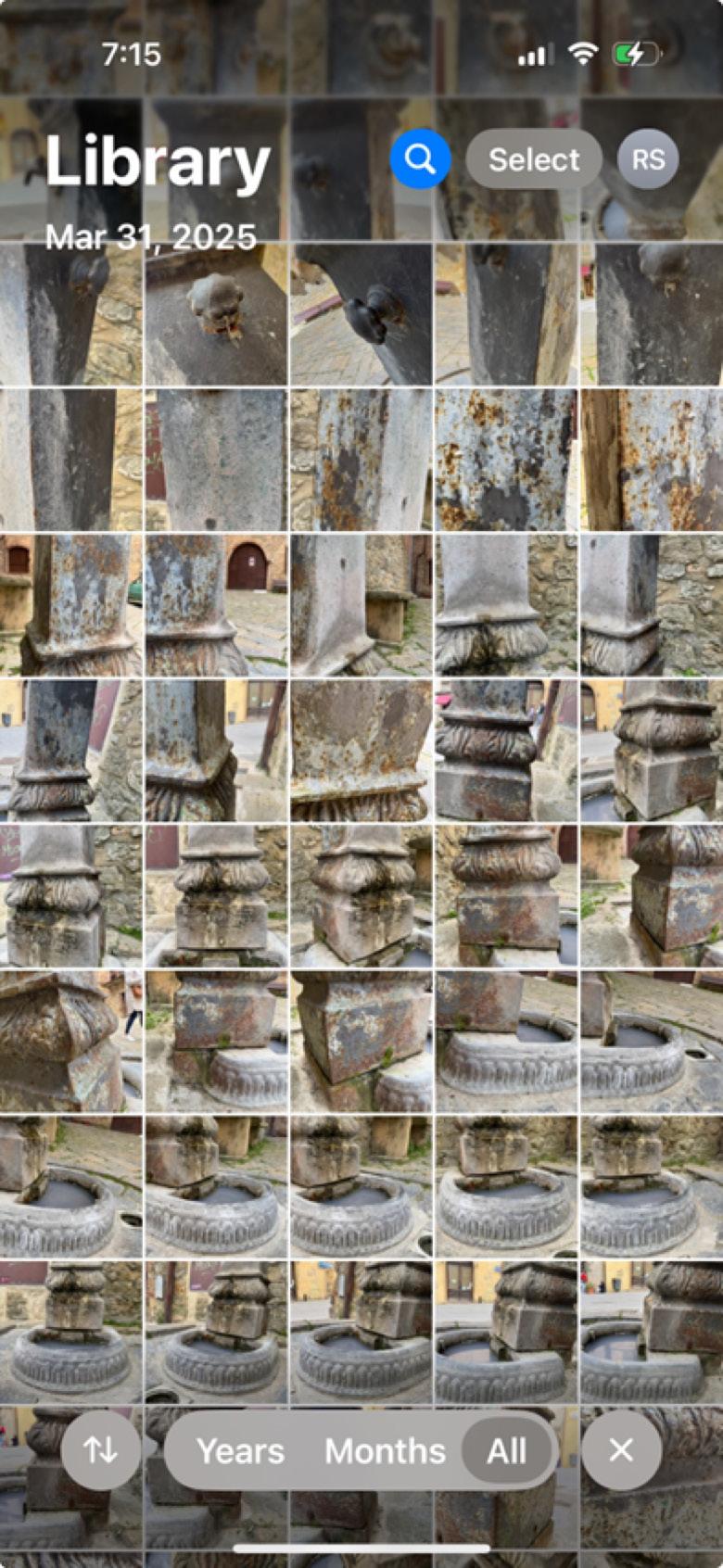
Some more new features I noticed on the UI - Scan to Mesh

Exports Image of the Current View - you can export RealView images at each scan location.
And now you see a ReCap Mesh tab in Revit - even back to Revit 2024.3!

A nice touch - I can process the XYZ format Revit and convert them to RCP in ReCap Pro 2026 and link them into my Revit 2024 projects without missing a beat - the absence of ReCap Pro 2025 is not felt at all. Small mercies, eh?
However, life is not all moonlight and roses, O Gentle Reader - this brings me to the dragonfly in the ointment. When I go to open an existing mesh model (even one that I’ve JUST created - take a look at the proof)

ReCap 2026 does not seem to know what to doand I’m not the only one who seems to think so! This screenshot is utterly misleading - to put it politely. It opens an FBX version of the mesh in ACC. And clicking on the little folder icon does precisely nothing. Not helpful at all.

If I can’t open the mesh in ReCap, how can I edit it?
Please tell me what I’m missing!!
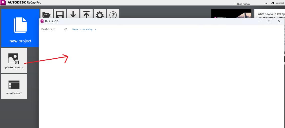
This is a known issue that has been acknowledged in this Forum thread. Prematurely released, perchance?

SERIOUSLY AUTODESK?
Moral of the story- you might as well keep ReCap Photo 2025 on your machine
On that note, I now bid thee farewell, O Gentle Reader! Till the next issue of Inside Track - KEEP REVIT-ING (or rather, RECAP-ing!!

A bit about myself. I’m the BIM Manager at Abonmarche, based in glorious Grand Rapids, Michigan (Great Lakes, anyone?). Started my Autodesk journey with AutoCAD Release 10 (remember that dreary DOS interface - and the need for super-duper spelling skills?). Learned enough Revit to stay one chapter ahead of college students in the classroom. That changed in a hurry when I made a triumphantly painful return to industry as a BIM Specialist and had to use Revit in the worst way possible. I HATED it and grieved for my beloved AutoCAD Until I figured Revit out - the rest, as they say, is history. Autodesk Expert Elite in 2018, presenter at Autodesk University since AU2019 (and I have Best Speaker awards for 2021 and 2022 to show for it!). And now here I am, to educate, enlighten, and hopefully, entertain
Please let us know if you have some news to share with us for future issues. Likewise, if you are a featured product or news item user and would like to write a review, we want to know. Drop me a line at: rinasahay@gmail.com. We’d love to hear from you!
Bright Ideas for a Bright Future

AUGIWORLD brings you the latest tips & tricks, tutorials, and other technical information to keep you on the leading edge of a bright future.
