


One of the first commands that new CAD/ BIM users learn are the View Controls. Knowing where you are in a file and how to move around is critical. Very quickly after they have drawn their first line, wall or circle, users need to know how to change the view angle/ scale of the object they have just created. I am not going to talk about the view tools, but about controlling the view of people. Tech Managers need to know how to change views also, but the views they change are not objects on a screen, but perspectives in people’s minds. Tech Managers need to know when and how to make big things smaller and small things bigger.
There are times when you need to turn the big things into smaller things. Negative thought can start to enter the workplace environment. When things go awry, people get concerned. They can become overly focused on the downside, slide into being disheartened or even dabble with despair. But things are usually not that bad and you can help them retain the positive view when their view is cloudy.
We all make mistakes and sometimes in the heat of a project deadline, a mistake can impact progress toward a deliverable. When mistakes are made by others, you need to help folks keep a proper perspective on the impact of the issue. This starts by making sure that the issue is framed at the correct scale. Most mistakes can be corrected easily and quickly, but folks that are in the midst of a derailment can lose sight of how to get back on track. Mistakes seldom cause long term problems.
They can be fixed, and folks can get back to work quickly. Remind people of that and reduce the scale of the impact in people’s minds. Step in, offer solutions, remind them that it is not as bad as they might think and get people back to work.
While most mistakes can be quickly resolved, some are very impactful to the entire team. The ones that are bigger need to be managed so that the impression of the scale does not expand beyond what it reasonable. Managers need to take control of the messages that circulate in the team when a mistake happens. If the concern level is getting bigger, they can seek to keep it smaller and bring calm to the conversation. They need to control the spread of exaggerations as well as addressing the actual mistake. Dive in and help the team get back to normal while reminding them that this problem can be alleviated.
Problems that spread to entire projects can generate concern with management. It is best for you to convey the message about larger impact delays directly up the leadership ladder as far as is appropriate. Keep the conversation direct and frame the issue as it relates to the short- and longterm repercussions. Convey what the possible disturbance to the project might be but remind them that it is not expected to get that bad. Keep management posted on the progress being made to “right the ship” and let them know that this is a top priority. While addressing the large-scale problem, your goal is to keep the concern level as small and appropriate in managements mind.
Implementation of Sheet Sets in AutoCAD Architecture is quite easy once you get into it and is an excellent tool to use. A sheet set is an organized and named collection of sheets (basically selected layouts) from several drawing files. With the Sheet Set Manager, you csan manage drawings as sheet sets.
A sheet set can be created with the Create Sheet Set wizard. In the wizard, you can either create a sheet set from scratch based on existing drawings or use an example sheet set as a template. Layouts from specified drawing files are imported into the sheet set. The associations and information that define a sheet set are stored in a sheet set data (DST) file. When you create a new sheet set using the Create Sheet Set wizard, a new folder is created as the default sheet set storage location. This new folder, which is named AutoCAD Sheet Sets, is located in the My Documents folder.
It is important to note that the DST file should be stored in a network location that is accessible to all sheets set users on the network and mapped using the same logical drive. It is strongly recommended that you store the DST and the sheet drawings in the same folder. If an entire sheet set needs to be moved, or a server or folder name changes, the DST file will still be able to locate the sheets using relative path information.
Before you begin creating a sheet set, several steps should be completed. First, drawing files need to be consolidated. Move the drawing files to be used in the sheet set into a small number of folders in order to simplify sheet set administration. Second, eliminate multiple layout tabs. Each drawing you plan to use in the sheet set should have only one layout to be used as a sheet in the sheet set. This is important for access to sheets by multiple users, as only one sheet in each drawing can be open at a time. Third, create a sheet creation template. Create a drawing template (DWT) file to be used by the sheet set for creating new sheets. You specify this template file in the Sheet Set Properties dialog box or the Subset Properties dialog box. Fourth, create a page setup overrides file. Create a DWT file to store page setups for
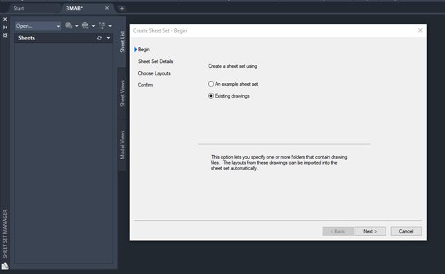
plotting and publishing. This file can be used to apply a single page setup to all sheets in a sheet set, overriding the individual page setups stored in each drawing. It is important to note here that although it is possible to use several layouts from the same drawing file as separate sheets in a sheet set, it is not recommended. This makes concurrent access to each layout by multiple users impossible. This practice can also reduce your management options and can complicate the organization of your sheet sets. To open the Create Sheet Set Wizard, click on the View tab, Palettes panel and select Sheet Set Manager. When the palette opens, click the drop down that says Open and select New Sheet Set.
In the Create Sheet Set wizard, when you choose to create a sheet set from an example, the example sheet set provides the organizational structure and default settings for the new sheet set. You can also specify that folders are created corresponding to the subset storage paths of the sheet set. After you create an empty sheet set with this option, you can import layouts or create sheets individually.
In the Create Sheet Set wizard, when you choose to create a sheet set from existing drawing files, you specify one or more folders that contain drawing files (see Figure 1). With this option, you can specify that the subset organization for the sheet set duplicates the folder structure of the drawing files. The layouts from these drawings can be imported into the sheet set automatically. You can easily add more folders containing drawings by clicking the Browse button for each additional folder.
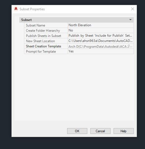
under Subset Name, enter the name of the new subset and click OK (see Figure 3). You can drag the new subset anywhere on the sheet list, even under other subsets. It is important to note that if you want to create a subset under an existing subset, you can right-click the existing subset. On the shortcut menu, click New Subset.
If you move a sheet to a different folder, you should re-associate the sheet to the sheet set with the Sheet Properties dialog box to correct the path. For any relocated sheet drawing, the paths for Expected Layout and Found Layout are displayed in the Sheet Properties dialog box. To re-associate the sheet, click the path in Expected Layout and then click to navigate to the new location of the sheet. It is important to note that you can quickly confirm whether a sheet is in the expected folder by looking at Details at the bottom of the Sheet List tab. If the selected sheet
is not in the expected location, path information for both Expected Location and Found Location is displayed in Details.
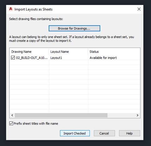
To re-associate a sheet in the sheet set, begin by clicking the View tab on the Palettes panel and select the Sheet Set Manager. In the Sheet Set Manager, open a sheet set. Now on the Sheet List tab, open the sheet that you want to re-associate. Next, in the Sheet Set Manager, right-click the sheet you wish to remove and then click Remove Sheet. Save the drawing. In the Sheet Set Manager, right-click the sheet set and click Import Layout as Sheet. In the Import Layout as Sheet dialog box, click Browse for Drawings and navigate to the drawing you wish to use. Click the check box of the layout to be re-associated as a sheet in the current sheet set and click Import Checked (see Figure 4).
From the Model Views tab, you can easily add a view to a sheet by placing

Implementation is the execution of an idea, the realization of a specification, algorithm, or vision into a tangible result—whether that be a software system, a workflow, or a process. In the world of design and engineering, it’s more than just installing a program; it’s about adopting new tools, transforming habits, and evolving how we work together to deliver great outcomes.
For Gresham Smith, the journey of implementation has run parallel with the evolution of technology in the AEC industry. Our transition from drafting on mylar sheets to collaborative modeling environments like BIM isn’t just a story about software, it’s a story about people.
It was the year 2 B.C.—not before Christ, but “Before Computers” at Gresham Smith—and I had just started as an intern, still in school but hungry to learn. Back then, our design process was tactile and analog. Teams were structured around an architect leading coordinators, detailers, and a few interns like myself, each playing an essential role in shaping the built environment through hand-drafted plans.
We worked with ink on mylar sheets, and a unique system of drafting called Unigrafs, developed by Edgar Powers Jr. Unigrafs wasn’t just a technique, it was a philosophy of precision. It involved photographic processes, printing negatives, and producing finished drawings using plates and printing presses. It was
complex, but highly organized, and it left a lasting mark on how we approached documentation.
In 1983, Gresham Smith began our first major implementation effort: moving from manual drafting to Computer-Aided Design (CAD). Our established Unigrafs standards smoothed the transition, providing a structured method to organize layers, elements, and lineweights in the digital environment.
At the time, Gresham Smith had five offices, each one relatively autonomous, managing its own teams, projects, and software platforms. While this structure allowed for flexibility, it became a challenge as the firm grew and project demands shifted. A downturn in the economy around 2008 highlighted the issue most: some offices were overloaded with billable work, while others had staff charging overhead.
In response, leadership made a pivotal decision—to promote workforce and project sharing across offices. But teams were using different versions of CAD: multiple variations of MicroStation and AutoCAD, plus a smaller contingent on HOK Draw. This software fragmentation made collaboration difficult. Something had to change.
Given that much of our Department of Transportation work relied on MicroStation, and it already represented about 70% of the firm’s CAD platform usage, Gresham Smith standardized on MicroStation. The rollout wasn’t easy, training had to be provided at scale, and staff were asked to switch up familiar workflows. But it was a necessary step toward better integration across the firm.
While we were refining our CAD standards, the industry wasn’t standing still. A new paradigm was emerging known as Building Information Modeling (BIM). Unlike CAD, which focused on 2D and 3D representation, BIM introduced data-rich models that supported lifecycle management, interdisciplinary collaboration, and a more holistic approach to design documentation.
Rather than dictate a solution from above, this time leadership took a different tack: they empowered the practice. Two leading platforms were placed
on the table—Bentley Architecture and Autodesk Revit—and our teams were invited to explore and evaluate both.
Two teams were formed and assigned similar project tasks using each platform, then asked to evaluate based on a scorecard of key criteria:
• Availability of training materials
• Quality and reusability of component parts
• Technical support and vendor engagement
• User-friendliness
• Third-party development support
• Analytics capabilities
• Ease of configuration
Documentation efficiency
The project teams didn’t just test the software— they lived with it, developed real work through it, and came together afterward to share their experiences. This open, participatory model of evaluation created a sense of ownership across the firm. Instead of being passive recipients of a topdown change, staff became active contributors to choosing the direction of our digital future.
Once Autodesk Revit was selected, we modeled our rollout on some of the strategies that had worked well in the CAD transition—but also introduced new methods tailored to our evolving needs.
• We created standardized “starter kits” of components and details to speed up modeling.
• We launched “just-in-time” training, scheduled the week before a team began using BIM in a live project.
• Our Practice Technology staff remained embedded and hands-on, supporting teams in the real-world problems of model complexity, remote workflows, and software quirks.
There were challenges—models grew large, networking between locations got complicated, and the learning curve was steep. But there was one game-changing difference: attitude. Our teams were no longer reluctant adopters, they were advocates. They had helped choose the platform, and were invested in making it work.


Picking software can feel like a big deal, especially when you think about the cost and buy-in. But it doesn’t have to be stressful. Just like with a new gadget, the flashy features might grab your attention, but you need something that works for you. A salesperson will probably rave about all the great features, but the real question is: does it fit your needs? After all, you don’t want software that promises to cook you breakfast but ends up burning your toast. So, how do you make sure you’re picking the right one? Let me share a couple of stories that might help— and then I’ll walk you through a process that’s worked for me.
Years ago, I was chatting with a superintendent who was frustrated with his daily grind. I asked him, “If you could have a piece of software do anything to make your job easier, what would it do?” He lit up, rattling off a detailed wish list of how it could simplify his tasks. I thanked him, stepped out for five minutes, and came back with something I’d


been testing on my personal iPad—an app I’d found by keeping up with industry trends (despite no R&D budget at my company). It matched his needs almost perfectly. He loaded it onto his device, and within a week, his team was using it. A month later, it was standard for all new projects. No PowerPoint, no ROI charts—just word-of-mouth from someone who lived the problem.
That experience taught me something: selecting software isn’t just about features or specs. It’s about solving real problems for real people—and that starts with understanding what you need. I recall an instance when I had lunch with a former colleague who’d joined a new company. She asked about issues at my job, listened to me vent, and said, 'I can solve that.'" She explained her product, aligning it with what I needed. I tried it that day, demoed it the next, and issued a purchase order by the week’s end. She’d asked the right questions, listened, and delivered. It wasn’t just a sale—it was a solution built on trust.
continuous support. Recognizing and integrating champions throughout this lifecycle ensures consistent momentum and meaningful adoption.
BIM Champions often share a few essential characteristics:
• Passion for technology: They stay curious about new tools, platforms, and workflows.
• Strong communication skills: They can explain complex concepts clearly to a wide range of staff.
• Empathy: They understand team frustrations and tailor solutions to actual user needs.
• Influence without authority: Even without formal leadership roles, they earn trust through expertise and consistency.
• Lifelong learners: Champions constantly seek better ways to solve problems and improve productivity.
A BIM Champion’s daily work is deeply embedded in the implementation process. Examples of what some of their responsibilities may include:
• Introducing and training staff on tools like Revit, ACC, or other cloud collaboration platforms.
• Troubleshooting real-time software issues to prevent productivity losses.
• Gathering feedback from users and refining implementation strategies accordingly.
• Piloting tools or workflows on smaller projects before recommending firmwide rollout.
• Maintaining BIM standards documentation, internal wikis, or best practices libraries.
Their daily impact is not always dramatic, but it’s cumulative. They enable smoother adoption, reduce user frustration, and keep implementation efforts on track. Champions thrive when feedback flows in both directions. I would highly encourage open sharing, whether it’s through informal coffee chats, a Teams channel, or monthly ‘BIM Wins & Woes’
huddles. These touchpoints help champions surface what’s working (and what’s not) so implementation can stay nimble.
A BIM Champion might develop a Dynamo script to batch rename views based on a project naming convention. After testing it with a small team, they host a 15-minute lunch demo and share a PDF guide with examples, saving hours of manual renaming across multiple projects. Or they may use C# or Python to create a toolbar that gives users easier access to your developed standards, workflows and best practices.
One BIM Champion can only go so far. To truly scale implementation success, firms should cultivate a network of champions across different disciplines and offices. This could take the form of:
• A dedicated “BIM Council” or “Technology Committee”
• A rotating group of staff who lead weekly or monthly tech sessions
• Shared folders, Teams channels, or knowledge hubs where champions share tips and resources
By building a network, knowledge and support are decentralized, making the entire organization more resilient and agile.
One lesson I’ve learned over the years: implementing new Revit standards isn’t just a technical rollout, it’s a cultural shift. Team members often have deeply ingrained workflows, and introducing changes requires not only explaining the technical benefits but also addressing hesitations and resistance. BIM Champions play a crucial role in bridging this gap by reinforcing not just how we model, but why these changes are necessary for improving collaboration, efficiency, and project outcomes. Through internal blogs, weekly tips, quick-win workflows, and fostering open communication, we make the standards approachable, relatable, and even exciting for project teams, ensuring smoother transitions and long-term adoption.
Leadership has a critical role to play in empowering champions. Too often, firms expect champions to lead change while juggling project deadlines, with no additional time or recognition. To truly enable them:
• Allocate protected time to focus on training, development, and support
• Offer recognition, bonuses, or career development opportunities
• Involve them in firmwide strategy decisions around BIM and technology
• Provide access to conferences, beta programs, and learning platforms
• Weekly 1:1 check-in with project teams
• Internal wiki updates every two weeks
• Attend or lead one lunch-and-learn per quarter
• Feedback summary reports to leadership
An empowered champion is not just more effective, they’re more likely to stay and grow within the organization.
My own journey as a contributor and advocate in the BIM space has highlighted how valuable champion-led implementation can be. Leading initiatives like Newforma Konekt, producing weekly BIM Mastery tips, publishing the monthly Buildings BIM Bulletin, and contributing to AUGI World content have all underscored a recurring theme: empowered, knowledgeable individuals make all the difference. These experiences have not only formed my perspective but also helped shape the strategies we use to support successful technological rollouts.
When I first joined Garver, I developed an ambitious timeline for implementing BIM within our MEPF team. It was a bold strategy, designed to push boundaries and accelerate our adoption of advanced workflows. Thanks to the dedicated efforts of our BIM Champions, not only did we rise
to the challenge, but most of the milestones were achieved ahead of schedule. These champions played a critical role in building workflows, mentoring their peers, and troubleshooting issues, ensuring the implementation was both efficient and impactful. As our group’s BIM Manager, I helped a project team navigate tricky IFC coordination issues with an external architect using ArchiCAD, turning what could have been a coordination nightmare into a smooth exchange of models and data.
Technology alone doesn’t drive implementation. People do. BIM Champions are the human engine behind successful change in the AEC industry. They translate firm vision into practical action, help teams navigate new tools, and turn innovation from aspiration into reality.
Every firm has potential champions, it’s up to leadership to find them, support them, and build a culture where they can thrive. If you want your next implementation to succeed, don’t just focus on the software. Focus on your champions.

Jason Peckovitch is an Autodesk Revit Certified Professional for Mechanical and Electrical Design located in SE Iowa. He is a BIM Manager for Garver’s Buildings Business Line, specifically MEPF. Garver has more than 50 offices across the United States and more than 1200 employees. His CAD/BIM career spans over 25 years but he didn’t switch to the AEC Industry until 2007 as a Mechanical HVAC Drafter and transitioned into BIM Management shortly after where he has been working since. Jason is also the father of three children; Shelby – 12, Blake – 10 and Logan - 7, a published photographer, gamer, and car/tech guy. He can be reached at jmpeckovitch@ garverusa.com.
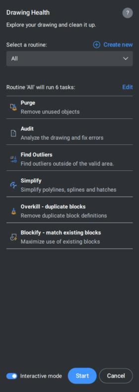
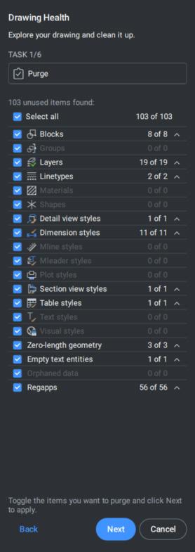
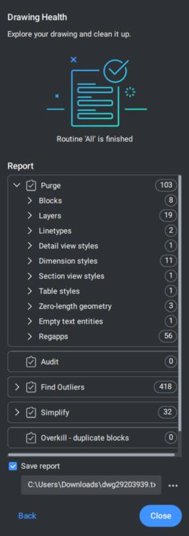
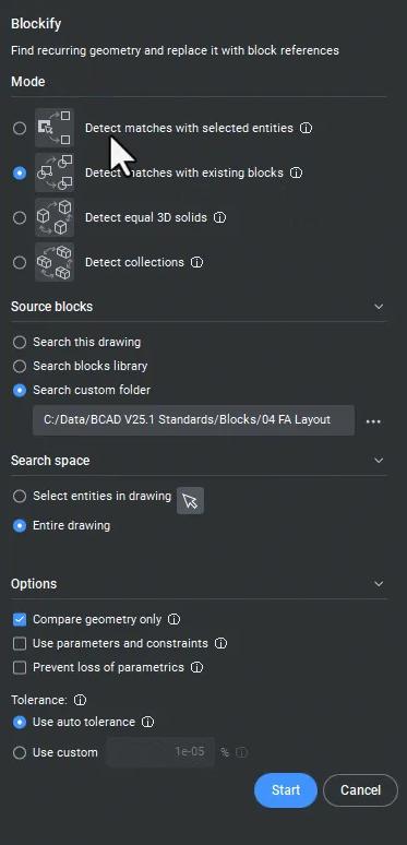
Bricsys® highly encourages companies to implement DWGHEALTH into their workflow. On average, the client’s drawing file size is reduced from 25-50%. The average time to open the drawing has decreased 50-75%. In addition, drawings created with other CAD software are now able to open, function, and perform as expected after DWGHEALTH. Lastly, with the reduction in overall file sizes across the company, the client no longer
needs to think about the expansion of new server hardware or additional cloud storage.
The key to success, whether in fitness or drafting, is consistency. Implementing DWGHEALTH into your standard workflow ensures sustained improvements in drawing quality.
• Weekly Health Checks – Just like a weekly fitness review, set up a routine where team members run DWGHEALTH on active projects.
• Team Training and Standards Enforcement –Conduct periodic training sessions to educate your team on best practices using DWGHEALTH, ensuring uniform standards.
• Integration with Templates and Custom Profiles – Configure DWGHEALTH settings within drawing templates, much like setting up a personalized workout plan tailored to your goals.
• Feedback and Continuous Improvement –Regularly review DWGHEALTH reports and adjust your workflow to address recurring issues, similar to refining a fitness routine based on progress.
See more DWGHEALTH in AUGIWORLD: AUGIWORLD-May2023
Using BricsCAD’s DWGHEALTH is like adopting a structured fitness plan. It requires dedication, learning, and routine implementation. By starting with the basics, gradually incorporating advanced features, and maintaining consistency, you can ensure that your drawings remain efficient, professional, and free from errors. Whether you’re working solo or collaborating with multiple subconsultants, a well-maintained .DWG environment leads to faster loading, higher performance, improved productivity and fewer drafting headaches. Just like in fitness, the results are worth the effort!
Want to explore the latest CAD and BIM software and toolsets in action? Watch the V25 Breakout Sessions and learn how to get more from intelligent tools and familiar features with Bricsys’ product experts. BricsCAD® V25 Launch
Bricsys® BricsCAD® is professional CAD software without compromise. Accelerate your time to deliverable without compromise on performance, cost, licensing flexibility, and data security. Not ready to buy? Download the free, 30-day trial of BricsCAD® at Bricsys.com. Would you like free lessons? We have that available with Bricsys Learning. Ready to migrate to BricsCAD®? Download the Migration Guide. The latest version of BricsCAD® improves the tools and features users love, as well as new functionality and UI that supercharge productivity. Follow us today on LinkedIn and YouTube.
Bricsys®, part of Hexagon®, is the global technology company that creates the BricsCAD® family of computer aided design (CAD) products and the Bricsys® 24/7 project collaboration platform. We are relentlessly committed to the success of our customers by offering cost-effective, missioncritical CAD software with industry-leading product support. Learn more at www.Bricsys.com.
Hexagon is a global leader in digital reality solutions. Learn more about Hexagon (Nasdaq Stockholm: HEXA B) at hexagon.com and follow us @ HexagonAB.

Mr. Craig Swearingen is a Global Implementation Specialist and Consultant at Bricsys. Currently, Craig provides migration and implementation guidance, management strategies, and technical assistance to companies which need an alternative, compatible CAD solution. Craig spent 19 years in the civil engineering world as a technician, Civil 3D & CAD power user, becoming a support-intensive CAD/ IT manager in high-volume production environments. Craig is a longtime AUGI member (2009), a Certified Autodesk® AutoCAD® Professional, and he enjoys networking with other CAD users on social media.
2. Do we have a dedicated 3D view that has been published?
If not, the +Create Issue button will be grayed out
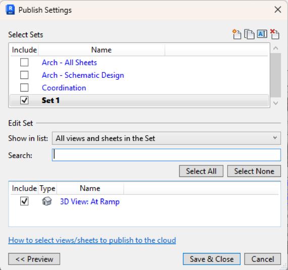
Tips - Don’t be afraid to create multiple published 3D views, for each room being reviewed. Give them a name that makes sense.
Create a Publish Set for views dedicated to creating issues. Add or remove views as needed.
Make sure to schedule Publishing in ACC! That leaves you covered - most of the time, that is!
a) If you’ve only just published the 3D view a minute or two ago, you may need to close and reopen Revit. Possibly a couple of times - it takes Revit a few minutes to realize that it has a dedicated view ready for issues.
So, let’s get started with a look at the first two - and most important - tools available to us on the Issues toolbar. Before we click on each tool to see what we shall see, we must make sure to be in a 3D view that has been published.
This shows us Model Issues that have been created as well as Clash tolerance and Clash tables that may be in the model. In this example we see that one issue has been created, and no action has been taken on the clash detection front.
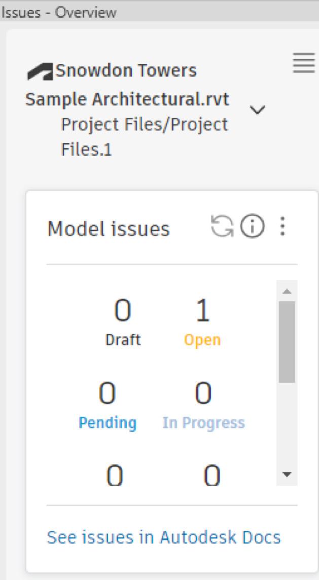
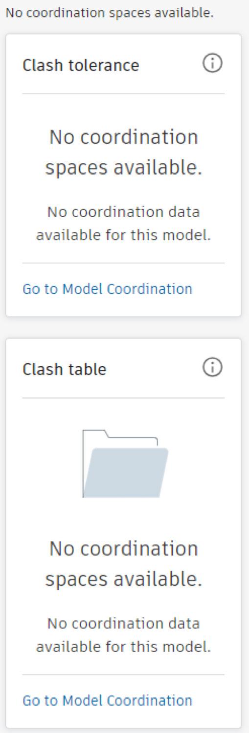
Have you noticed the links “See issues in Autodesk Docs” and “Go to Model Coordination”? They help you to jump directly to ACC from Revit.
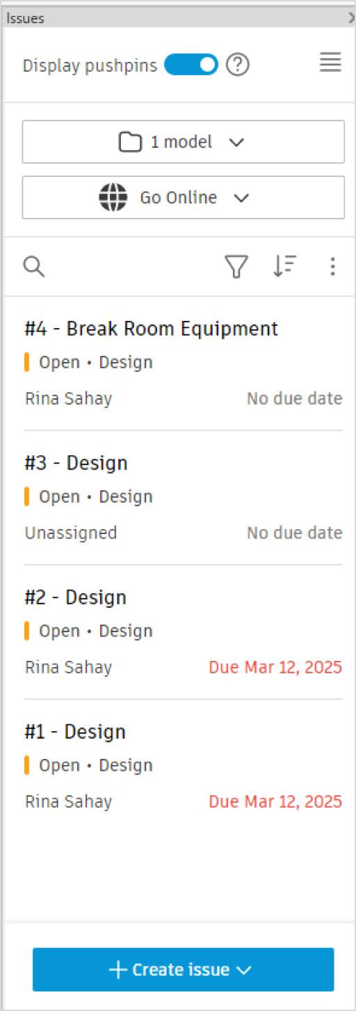
This brings up the Issues browser that shows
The issues that have been created
• Whether Open or Closed
• Due dates
• Who the issue has been assigned to
If you click on the three dots (I heard someone, call it the Snowman icon - how cute!) you get the options to either Export report (to PDF)
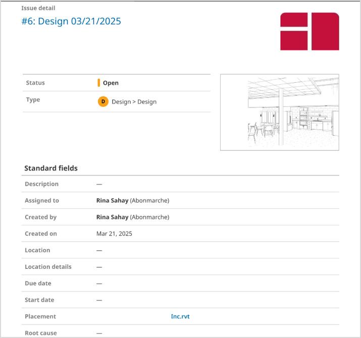
or Export as BCF
(What’s a BCF, you may ask, O Gentle Reader?
Bim Collaboration Format is an open standard file format used in the AEC industry to facilitate communication and collaboration on BIM models. Users can exchange model-based issues, comments, and markups between different BIM authoring tools)
All of this can be set up in Revit without opening ACC - all that you need to do is click the blue +Create issue button at the bottom of the browser.
This brings up a flyout with scrollable options that allow flexibility to tailor issues to specific situations -

These options are what really superpower this addin by bringing up the Issues browser that offers options like -
• Issue title
• Status
• Issue type
• Description
• Who it’s assigned to
• Due date
• Root cause
When an option is selected, you are prompted to click on the model to place “pushpins” and create an issue.

Click on the desired element to place the pushpinthe element will light up. Since I’m fussy and I don’t like dust collectors, I’m going to click on the open shelving to create a Design Issue to replace the open shelves with upper cabinets. Along with the infamous Spinning Wheel, you will see a progress message -
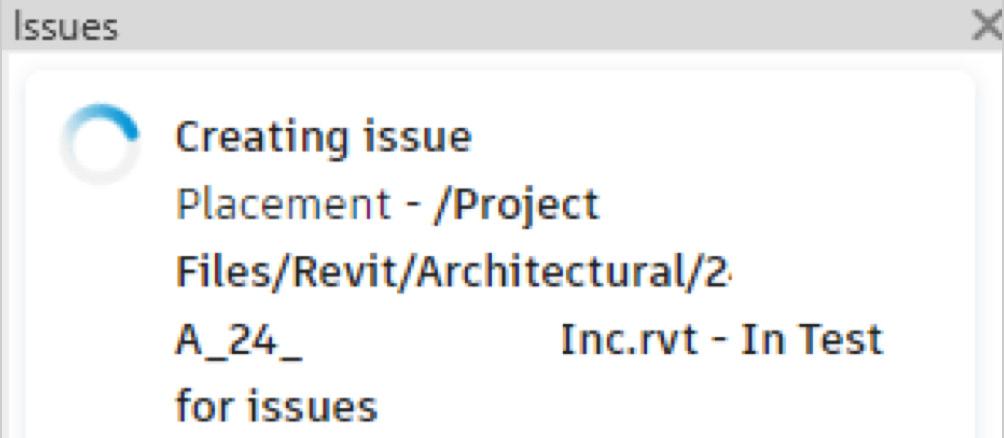
Look at the view - you will now see pushpins of any issues that have been created. Yellow is the active pushpin you’re editing. Other pushpins are a very becoming shade of pastel pink (great choice, Autodesk!). You will now see a thumbnail of the issue location in the view, and options in the browser that you can edit to customize the issue. Just click on the little pencil Edit icon and you’ll be rockin’ and rollin’!
Once crested, navigating to desired issues is easy
- in the Issues browser just click on the Issue to go straight to the published view.
And here’s the game changer - by default all issues created are published to the cloud. You can choose to Unpublish them if you want - but why on earth would you want to pull the teeth of this sterling innovation?
On that note, let’s make a quick trip to the Cloud to verify the results of our prior attempts. Issues are found under Docs.
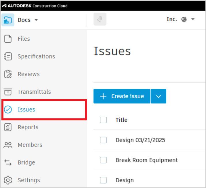
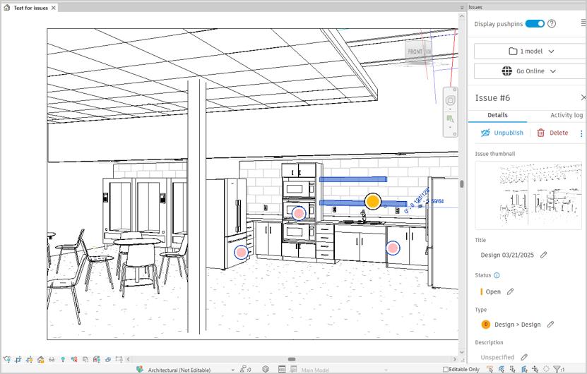
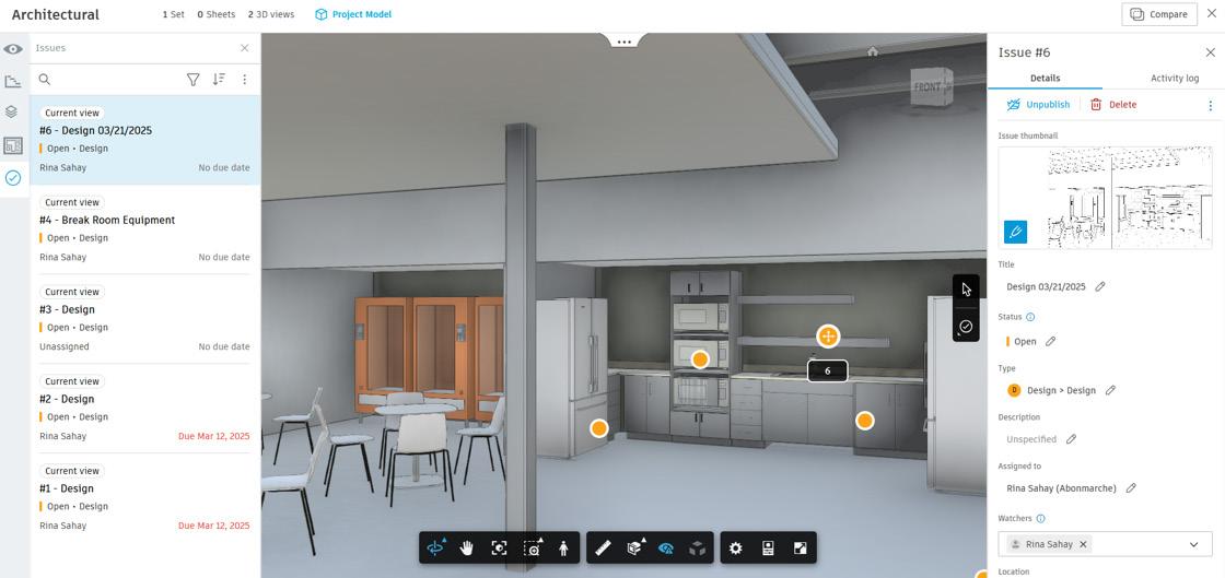
The lovely issue I’d just created shows up at the top of the list! Magical, isn’t it?
We can click on the issue, and we are taken to a screen which looks very familiar - are we back in Revit? No, we aren’t - we’re still up in the cloud!!
This interface not only allows you to edit and monitor the issue, but you can navigate through the view - orbit, walk, zoom, pan - to manage them. In addition, you can create an Issue in ACC and view and address it in Revit. Slick, isn’t it?
There’s more to this ACC capability but that would be the subject for another entirely different discourse.
Now, O Gentle Reader. You may still be wondering about the reason for all this excitement. Some points I’d like to repeat and emphasize for your edification -
• The Revit Issues Add-In establishes a bidirectional link between Revit and ACC.
• Issues can be created and viewed in each - and in real time.
• You don’t need Revit skills to view and review, create, assign, and track project issues.
• All of this without the need to step into additional tools (for instance, Bluebeam or Plangrid).
• Issues can be exported from both Revit and ACC as PDFs.
This makes things SO much easier for non-Revit using Project Managers, for instance, to keep tabs
on what’s going on in the project with fewer tools - hence fewer loose ends and less clutter. And this tool comes to you along with the ACC you already know and love. So why not leverage it?
With that final question, I now bid thee farewell, O Gentle Reader! Till the next issue of Inside TrackKEEP REVIT-ING!

A bit about myself. I’m the BIM Manager at Abonmarche, based in glorious Grand Rapids, Michigan (Great Lakes, anyone?). Started my Autodesk journey with AutoCAD Release 10 (remember that dreary DOS interface - and the need for super-duper spelling skills?). Learned enough Revit to stay one chapter ahead of college students in the classroom. That changed in a hurry when I made a triumphantly painful return to industry as a BIM Specialist and had to use Revit in the worst way possible. I HATED it and grieved for my beloved AutoCAD Until I figured Revit out - the rest, as they say, is history. Autodesk Expert Elite in 2018, presenter at Autodesk University since AU2019 (and I have Best Speaker awards for 2021 and 2022 to show for it!). And now here I am, to educate, enlighten, and hopefully, entertain.
