PRODUCT FOCUS
Revit 2019 – MEP
Figure 4
Second, the tags, with their desired parameters and graphics, must be created for just this purpose. The danger that creeps in here is when different symbols are needed for elements of the same Revit category. Nothing is preventing the user from tagging an element with a tag using the wrong symbol. Or, if during the course of design the element changes types, the symbols in plan view also change. The symbol in the tag in the riser or diagram will then be incorrect. This is not a big problem if your tags are not indicating different symbols. Third, once tagged, all the tags must be manually moved to their desired locations. This can be tedious depending on the number of elements. Once located as desired, don’t forget to pin all your tags! Fourth, the scale of the view must be such that it will fit on a sheet. Decide this sooner rather than later to avoid having to adjust annotative elements if the view scale changes (Figure 4).
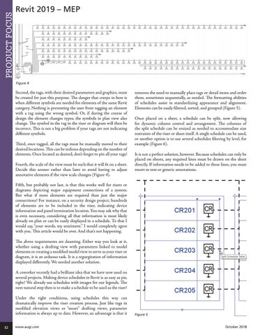
removes the need to manually place tags or detail items and order them, sometimes sequentially, as needed. The formatting abilities of schedules assist in standardizing appearance and alignment. Elements can be easily filtered, sorted, and grouped (Figure 5). Once placed on a sheet, a schedule can be split, now allowing for dynamic column control and arrangement. The columns of the split schedule can be resized as needed to accommodate size restraints of the riser or sheet itself. A single schedule can be used, or another option is to use several schedules filtering by level, for example (Figure 6). It is not a perfect solution, however. Because schedules can only be placed on sheets, any required lines must be drawn on the sheet directly. If information needs to be added to these lines, you must resort to text or generic annotations.
Fifth, but probably not last, is that this works well for risers or diagrams depicting major equipment connections of a system. But what if more elements are required than just the major connections? For instance, on a security design project, hundreds of elements are to be included in the riser, indicating device information and panel termination location. You may ask why that is even necessary, considering all that information is most likely already on plan or can be easily displayed in a schedule. To that I would say, “your words, my sentiment.” I would completely agree with you. This article would be over. And that’s not happening. The above requirements are daunting. Either way you look at it, whether using a drafting view with parameters linked to model elements or creating a modified model view to serve as your riser or diagram, it is an arduous task. It is a regurgitation of information displayed differently. We needed another solution. A coworker recently had a brilliant idea that we have now used on several projects. Making device schedules in Revit is as easy as pie, right? We already use schedules with images for our legends. The next natural step then is to make a schedule to be used as the riser! Under the right conditions, using schedules this way can dramatically improve the riser creation process. Just like tags in modified elevation views or “smart” drafting views, parameter information is always up to date. However, an advantage is that it 32
www.augi.com
Figure 5 October 2018