CONNECTORS In the world of MEP, it isn’t done until the correct connectors are added. Connectors are the fundamental element that differentiates MEP from Architectural in Revit. Connectors pass information from family to family. Current, air, gas, fluids, and their properties are transferred and combined through the use of connectors. Connectors want to live on a face of a solid form. Their locations can be very predictable, like the open end of a pipe, conduit, or duct fitting, or simply placed in the center of a light fixture.
PRODUCT FOCUS
Revit MEP 2017
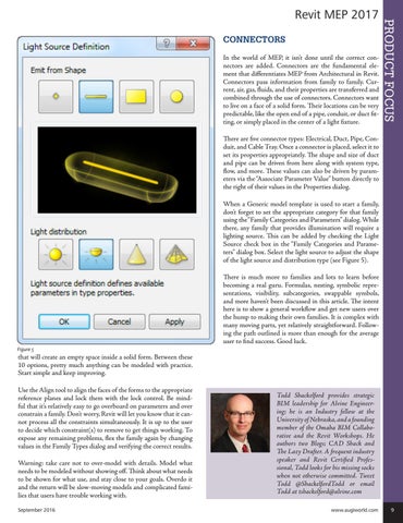
There are five connector types: Electrical, Duct, Pipe, Conduit, and Cable Tray. Once a connector is placed, select it to set its properties appropriately. The shape and size of duct and pipe can be driven from here along with system type, flow, and more. These values can also be driven by parameters via the “Associate Parameter Value” button directly to the right of their values in the Properties dialog. When a Generic model template is used to start a family, don’t forget to set the appropriate category for that family using the “Family Categories and Parameters” dialog. While there, any family that provides illumination will require a lighting source. This can be added by checking the Light Source check box in the “Family Categories and Parameters” dialog box. Select the light source to adjust the shape of the light source and distribution type (see Figure 5). There is much more to families and lots to learn before becoming a real guru. Formulas, nesting, symbolic representations, visibility, subcategories, swappable symbols, and more haven’t been discussed in this article. The intent here is to show a general workflow and get new users over the hump to making their own families. It is complex with many moving parts, yet relatively straightforward. Following the path outlined is more than enough for the average user to find success. Good luck. Figure 5
that will create an empty space inside a solid form. Between these 10 options, pretty much anything can be modeled with practice. Start simple and keep improving. Use the Align tool to align the faces of the forms to the appropriate reference planes and lock them with the lock control. Be mindful that it’s relatively easy to go overboard on parameters and over constrain a family. Don’t worry, Revit will let you know that it cannot process all the constraints simultaneously. It is up to the user to decide which constraint(s) to remove to get things working. To expose any remaining problems, flex the family again by changing values in the Family Types dialog and verifying the correct results. Warning: take care not to over-model with details. Model what needs to be modeled without showing off. Think about what needs to be shown for what use, and stay close to your goals. Overdo it and the return will be slow-moving models and complicated families that users have trouble working with. September 2016
Todd Shackelford provides strategic BIM leadership for Alvine Engineering; he is an Industry fellow at the University of Nebraska, and a founding member of the Omaha BIM Collaborative and the Revit Workshops. He authors two Blogs; CAD Shack and The Lazy Drafter. A frequent industry speaker and Revit Certified Professional, Todd looks for his missing socks when not otherwise committed. Tweet Todd @ShackelfordTodd or email Todd at tshackelford@alvine.com www.augiworld.com 9