Routine Maintenance ProceduresGeneral Guidelines
To disassemble and assemble the columns, follow the instructions below. After reassembling the column ensure that the column does not leak by performing a hydrostatic leakage test. When assembling/dissembling attention should be paid to:
1. Always use the correct size tools. A comprehensive tool kit is provided with the columns. See Table below.
2. Ideally components should be at approximately room temperature (approximately 20°C). If not, take particular care as thermal expansion or contraction may make components fit more tightly and thus more difficult to disassemble.
3. Dismantled assemblies should be rested on a clean, dry surface
4. Pay particular care not to damage the edge of the flow cells
5. When unpacking column components and kits be careful not to scratch the inside of the column tubes
6. Be careful not to damage stainless steel surfaces by bumping, knocking or scratching
7. Do not over-tighten components and use correct torque settings as given in this guide.
8. Good engineering practices should be followed at all times and operations carried out in an approved and safe manner.
9. Components of the Evolve® 600 mm Process Column are heavy and an overhead hoist MUST be used to remove the adjuster unit. Further guidance is given in operating manual. ALL operations must be performed by two people.

Tube Replacement Kit Installation Guide - Evolve® 600 mm Process Column 3
Tool kit as supplied with Evolve® 600 mm Process Columns
Tool
Allen Key Set
Allen key 14 mm Adaptor & Torque
Wrench 3/8" Drive
Spanner 22 mm/24 mm
Spanner 19 mm/24 mm
Adjustable Spanner
Spirit Level
S/Driver with Wide Blade
O-Ring remover tool
Where used
Various locations
Tie Bar fixing Bolts
Flow tube adaptor, Adjuster Flow tube, Column Feet
Flanges bolts Adjuster, Fixed and locking flow cell nut
Locking nut and seal setting tube
Used to level the column
Removal of bed support retaining ring
Assists O-ring removal
Maintenance blocks General
Lifting Eyes and Fixings
Additional eye nuts to fit to tube unit during maintenance procedures
Tube Replacement Kit Installation Guide - Evolve® 600 mm Process Column 4
Fitting Instructions
Removal of Tube from Column
1. Use the instructions in the main operating manual to remove the adjuster cell assembly from the column.
2. Attach the spare set of eye bolts, provided with the original column, to the top tube flange
3. Using appropriate lifting slings or equipment attach the hoist to the eye bolts.
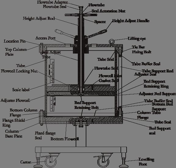
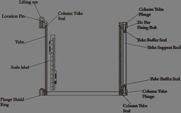
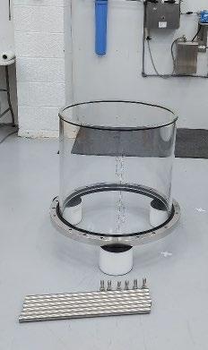
4. Identify column components using the schematic diagram shown below in Figure 1.
5. Using the correct Allen Key carefully remove top tube flange by removing the tube support rod bolts.
6. Retain the bolts and place the flange on a horizontal clean surface.
7. Remove the top tube seal from the flange and the tube buffer seal and discard
8. Lift out tube from the bottom flange, remove bottom tube seal and buffer seal and discard.
Tube Replacement Kit Installation Guide - Evolve® 600 mm Process Column 5
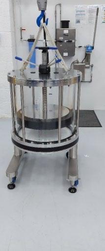
Figure 1: Schematic of Evolve® 600mm Process Column
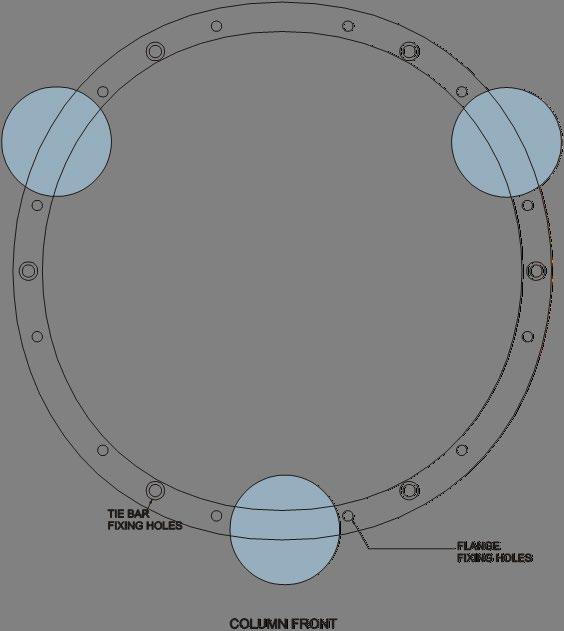
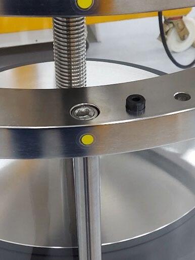
9. Attach the spare set of eye bolts provided with the original column, to the top tube flange. The correct position for these is located 2nd hole to the location pin. The hole is also recessed on the underside of the flange unlike the flange fixing bolt holes.
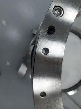
Location pin.
Lifting eye fixing hole, 2nd hole from location pin on tube flange
10. Identify the components on the schematic shown in Figure 3.
11. Attach the spare set of eye bolts provided with the original column, to the top tube flange
12. Using appropriate lifting slings or equipment attach the hoist to the eye bolts.
13.Using the correct spanners, remove and retain the column tube bottom flange bolts, washers and bolts
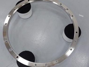
14. Place the maintenance blocks on the floor. These should be spaced to support the bottom flange and equally spaced - see Figure 4.
Tube Replacement Kit Installation Guide - Evolve® 600 mm Process Column 6
Figure 2: Reassembly of Adjuster Assembly
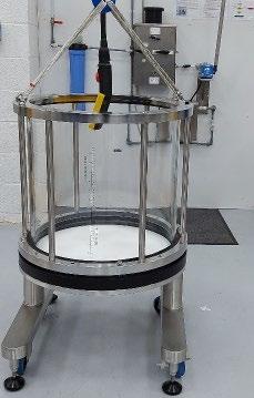
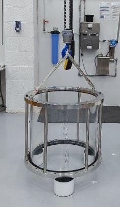
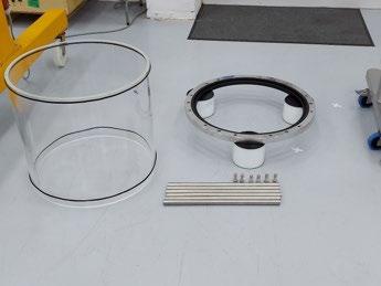
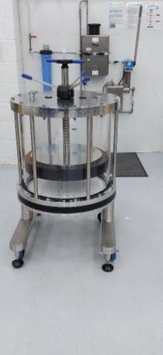
Figure 3 Column Tube unit
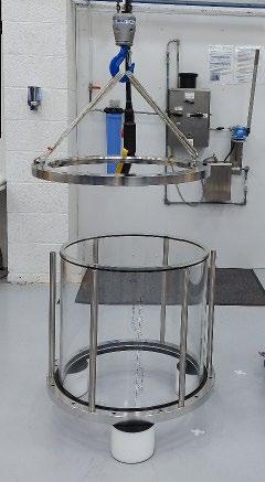
4: Maintenance block position to support the column tube unit
15. Lift the column tube unit away from the column base unit and move over the maintenance blocks. Slowly start to lower the unit; when approximately 5 cm above the maintenance blocks, pause and check position of the blocks
16. When maintenance blocks are in the correct position, ensure that access can be gained to the tie bar fixing bolts
17. Continue to lower the column unit until the unit rests on the blocks and hoist slings are slack.
18. Loosen the column top tie bar bolts using the socket adjuster. Remove and retain the tie bar fixing bolts from the top flange and remove the top flange. (Figure 6a)
Tube Replacement Kit Installation Guide - Evolve® 600 mm Process Column 7
Figure
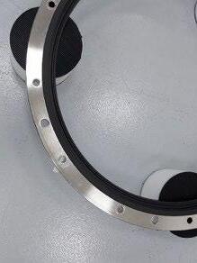
Figure 5: Tube unit after separation from Column Base
19. Loosen the column bottom tie bar bolts using the socket adjuster. Remove tie bars by manually twisting the bars (Figure 6b). Retain the tie bars and bottom fixing bolts.
20. Remove the bottom buffer seal from its location (Figure 7a) and slide it up the tube so it is clear of the flange shield ring. It is now possible to remove the tube.
21. Using correct lifting techniques, lift the column tube out of the flange shield ring (Figure 7b). This is a two-person operation Discard the tube and buffer seals. a)
7 (a-c): Removal of tube and flange shield ring
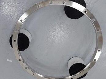
22. When tube is removed and moved clear of the maintenance area, lift out flange shield ring complete with tube seal and discard. Retain the stainless steel flange. (Figure 7c).
Tube Replacement Kit Installation Guide - Evolve® 600 mm Process Column 8
a) b)
Figure 6a, 6b: Disassembly of tube unit
b) c)
Figure
Reassembly of the Tube Unit
In the tube replacement kit, the tube is supplied ready for assembly with scale label, Evolve® label and rating plate and buffer seals on the tube wall.
1. Ensure the column bottom flange is located on the maintenance blocks and the blocks are evenly spaced but do not obscure the tie bar fixings Insert the flange shield ring into the stainless steel column flange. (Figure 8a) a)
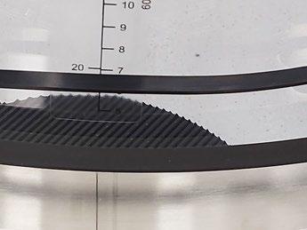
2. Identify the location of the alignment indicator as this will assist in orientating the tube correctly.
3. Identify the replacement bottom flange shield ring and locate into the bottom flange. (Figure 8b)
1. Fit the column bottom tube seal into the seal groove in the column flange shield ring. Ensure this seal is located completely within the groove. (Figure 8c and Figure 8d)
2. The buffer seals should be in place on the outside diameter of the tube at a distance approximately 2 cm from each end of the tube.
3. Before lifting the tube into place ensure the tube is orientated correctly. The correct orientation is that the scale label should be at the front of the column, perpendicular from the alignment indicators on the side of flange. See Figure 9 below.
Figure 9: Orientation of tube unit relative to alignment indicators
Tube Replacement Kit Installation Guide - Evolve® 600 mm Process Column 9
b) c) d)
Figure 8 (a-d): Reassembly of bottom tube flange
4. Lift and locate the acrylic tube. Ensure it is located centrally and evenly within the shield ring (Figure 10a). This is a two-person operation.
5. Locate and secure tie bars on the bottom flange using the bottom fixing bolts. Initially hand tighten the bolts, working diametrically opposite. When complete, use the torque wrench (set to 50 Nm) tighten the tie bar bolts, working diametrically opposite.
6. Using the hoist, lift the top column flange (Figure 10b). A top column tube seal is provided and although this seal is not process wetted it can be replaced. To do so, place the flange on a flat surface, remove lifting eyes and invert. Remove seal and replace. When complete turn over the top flange and reattach lifting eyes. Re-attach hoist and move over tube unit.
7. Place the flange over the tube unit so that the top fixing bolts can be engaged. Ensure alignment indicators are positioned correctly.
8. Lower the top flange (Figure 10c) and secure the bolts by hand but do not tighten the bolts.
9. Locate the upper and lower buffer seals into the bottom flange and underside of the top column flange.
10. Using the torque wrench (set to 50 Nm), tighten the tube support rod bolts located in the top column flange.
11. Recheck the bottom fixing bolts and tighten if necessary.
Tube Replacement Kit Installation Guide - Evolve® 600 mm Process Column 10
a)
b)
c)
Figure 10 (a-c): Reassembly of Column Tube Unit
Column Reassembly and Preparation for Use
Reassembly of the column is the reverse of disassembly and starts from column bottom upwards. Each sub assembly is reassembled before attached to the column.
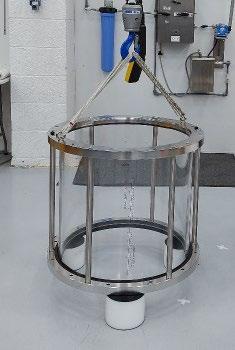
Assemble Tube Unit onto the Column base and Bottom Flow Cell
1. Attach appropriate lifting slings to the eye bolts located on the tube unit flange. Lift the tube unit.
2. Move the tube unit over the fixed end assembly (Figure 11a)
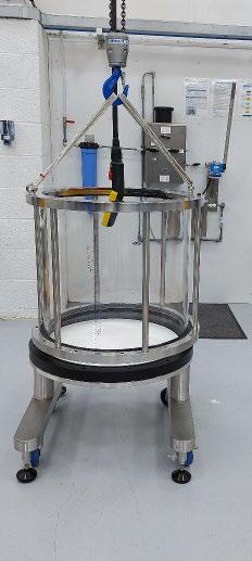
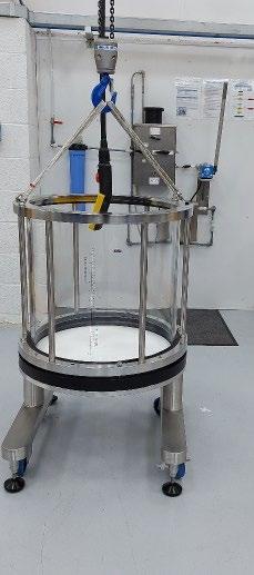
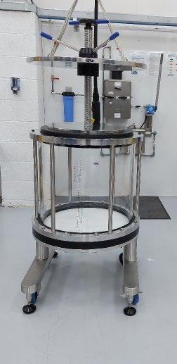
Figure 11 (a-c): Reassembly of Column
3. Align the tube unit using the alignment indicators (Figure 11b)
4. Replace the bottom column flange bolts/washers in the tube unit.
5. Slowly lower the tube unit and use the column bottom flange bolts to align the tube unit onto the bottom flange.
6. When tube unit is in place on column base, locate the column bottom flange nuts. Hand tighten, working diametrically opposite to ensure equal loading on the seal, then use the correct spanner to tighten, again working diametrically opposite.
7. Remove the eye bolts from the top flange and store with other column tools.
8. Attach appropriate lifting slings to the eye bolts located on the adjuster assembly. Lift the adjuster assembly.
9. Move the assembly over the column unit. Use alignment indicators to line up the adjuster. Slowly, position the adjuster unit into the column tube (Figure 11c). Alignment pins located in the top flange are provided to assist positioning (Figure 12a).
Tube Replacement Kit Installation Guide - Evolve® 600 mm Process Column 11
a) b) c)
CAUTION
10. Locate the top flange fixing bolts/washers. Hand tighten, working diametrically opposite to ensure equal loading (Figure 12b), then tighten fully using the correct spanner, again working diametrically opposite.
11. Remove lifting slings (Figure 12c). Column has been successfully assembled and ready for hydrostatic leak test and return to operation.
It is advisable to perform a Hydrostatic Leak test before the column is used.
Tube Replacement Kit Installation Guide - Evolve® 600 mm Process Column 12 a) b) c)
Figure 12 (a-c): Location of Adjuster Assembly completing Column Assembly