
Operating Manual and Installation Guide
Evolve® 600 mm Process Column


Operating Manual and Installation Guide Evolve® 600 mm Process Column 1 Table of Contents Column Hardware ......................................................................................... 5 Mechanical Description 5 Weights and Dimensions 7 Pressure Drop ............................................................................................ 8 Material Conformity 9 Chemical Compatibility ............................................................................... 11 Safety Guidelines ........................................................................................ 13 General .................................................................................................. 13 Operation ................................................................................................ 13 Design of Pressure Equipment ........................................................................ 14 Safe Lifting of Columns ................................................................................ 14 Column Handling during Operation and Maintenance ............................................. 16 Chemical Compatibility ............................................................................... 16 Over-pressurisation .................................................................................... 16 Installation and Column Set-up ....................................................................... 17 Installation .............................................................................................. 17 Removal from Packing Crate .......................................................................... 17 Column Preparation .................................................................................... 17 Column Operation ....................................................................................... 18 Hydrostatic Leak Test .................................................................................. 18 Example Method for Column Packing ................................................................ 20 Media Preparation ...................................................................................... 20 Column Packing - Constant Flow Rate Method ..................................................... 20 Unpacking ................................................................................................ 22 Cleaning and Storage .................................................................................. 22 Maintenance .............................................................................................. 24 Routine Maintenance Procedures - General Guidelines........................................... 24 Disassembly of Evolve® 600 mm Process Columns ................................................. 25 Adjuster Assembly ...................................................................................... 25
Operating Manual and Installation Guide Evolve® 600 mm Process Column 2 Disassembly of Tube Assembly 28 Disassembly of Fixed Assembly 30 Reassembly of Evolve® 600 mm Process Column 31 Troubleshooting ......................................................................................... 39 Kits, Spare Parts & Accessories ....................................................................... 43 Other Spare Parts and Accessory Kits ............................................................... 45 Contact Us ................................................................................................ 47 Appendix A: Certificate of Conformity .............................. Error! Bookmark not defined. Appendix B: Column Documentation ................................ Error! Bookmark not defined. IQ/OQ Quality Document - Column Sign off ..................... Error! Bookmark not defined. Revision History ......................................................................................... 48
Table of Figures
Operating Manual and Installation Guide Evolve® 600 mm Process Column 3
Figure 1: Evolve® 600 mm Process Column ............................................................. 6 Figure 2: Pressure Drop Evolve® 600 mm Process Column. 8 Figure 3: Orientation of lifting eye and lifting sling. 15 Figure 4: Correct location of eye nut on top plate of packing rig 15 Figure 5: Recommended angle between lifting slings ............................................... 16 Figure 6: Schematic of the column with part identification 19 Figure 7: Photograph of Evolve® 600 mm Process Column Adjuster unit removal from column tube. 25 Figure 8: Adjuster Assembly Evolve® 600 mm Process Column. 26 Figure 9 (a-c): Disassembly stages of the Adjuster Assembly 26 Figure 10 (a-c): Removal of Seal Adjust Tube 27 Figure 11a, 11b: Removal of Flow Tube ............................................................... 27 Figure 12: Tube Assembly Evolve® 600 mm Process Column. ....................................... 28 Figure 13: Position of lifting eye fixing points on column top flange. ............................ 29 Figure 14: Maintenance block position to support the column tube unit. ........................ 29 Figure 15: Fixed Assembly Evolve® 600 Process Column. ............................................ 30 Figure 16: Displaced bottom flow cell during disassembly ......................................... 30 Figure 17: Alignment Indicators on Evolve® 600 mm Process Columns ............................ 31 Figure 18 (a-c): Reassembly of Column Bottom Flow cell and base ............................... 32 Figure 19: Orientation of tube unit relative to alignment indicators ............................ 32 Figure 20a, 20b: Reassembly of Column ............................................................... 33 Figure 21: Adjuster Flow cell Inlet and Gasket position ............................................ 33 Figure 22: Inverting flow cell to fit flow cell inlet. ................................................. 34 Figure 23: Orientation of adjuster bed support into bed support retaining ring ............... 34 Figure 24: Location of bed support retaining ring onto the adjuster flow cell. ................. 35 Figure 25: Tightening of the bed support retaining bolt - correct positioning of tool. ........ 35
Operating Manual and Installation Guide Evolve® 600 mm Process Column 4 Figure 26a, 26b: Assembly stages of the Adjuster Assembly 35 Figure 27 (a-d): Assembly stages of the Adjuster Assembly – Connection to back of Adjuster Flow cell 36 Figure 28a, 28b: Reassembly of Adjuster Assembly .................................................. 36 Figure 29: Reassembly of Adjuster Assembly 37 Figure 30: Reassembly of Adjuster Assembly 37
31 (a-d): Location of Adjuster Assembly completing Column Refresh Procedure 38
Figure
Column Hardware
Mechanical Description
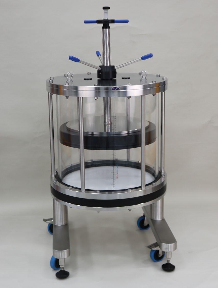
Evolve ® Process Column s are designed specifically for use in b iopharmaceutical a pplications. The column can be used in pilot or production scale c hromatographic processes.
A pressure rating of 3.0 bar, operating temperature range of 2-30 °C, and adjustable bed height makes this column suitable for a wide range of chromatography media types and chromatographic techniques.
This column has the following design features:
The entire flow path is non-metallic, which has the following advantages:
• Eliminates the risk of corrosion and process contamination
• Allows the use of high concentration sodium chloride solutions and Guanidine hydrochloride
• Prevents product inactivation through metal contact
Columns of this size experience significant load forces during operation. Stainless steel is widely used in column construction to withstand these forces and prevent damage to components occurring. In the Evolve® Process Columns design strategies, components are incorporated to maintain a non-metallic flow path without compromising the strength and integrity of the column.
The Evolve® 600 mm Process Column is fitted with hydrophilic polyethylene bed supports. These are manufactured from high density polyethylene and modified so that the internal and external surfaces are permanently hydrophilic.
• The bed supports allow the passage of air and fluid without the need for ‘wetting out’ procedures; traditional polyethylene bed supports are hydrophobic, and may require the use of high concentrations of organic solvents
• The material is permanently self-wetting for extended storage periods of 5 years or more
• A lower water intrusion pressure helps reduce the pressure drop through these supports; values do not limit typical chromatography applications.
• A uniform surface facilitates consistent flow across the diameter of the column, enabling an efficient separation process.
• Manufactured from high density polyethylene, the bed supports are robust allowing bed support thickness and column design to be optimised.
• The material has good chemical compatibility and enables a non-metallic flow path to be maintained through the column
• Easy installation of bed supports allows for rapid turnaround when change is needed
Operating Manual and Installation Guide Evolve® 600 mm Process Column 5
Sealing of the adjuster flow cell to the tube wall is achieved by an EPDM O-ring seal, and central activation ensures that compression is even. The mechanism to energise and deenergise the seal is simple and easy to operate.
Positioning of the adjuster assembly within the tube is straightforward; location pins and labelling to assist with orientation.
Evolve® 600 mm Process Columns are composed of three main sub-assemblies:
• Adjuster assembly - consisting of the adjuster flow cell assembly, backing plate, adjuster seal components, adjuster flange and a central height adjust threaded rod. Height can be adjusted over the range 50-460 mm.
• Tube unit – consisting of the column tube, top/bottom flanges and scale label
• Fixed assembly – flow cell assembly and flow tube, column base with lockable casters and levelling. column feet
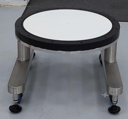
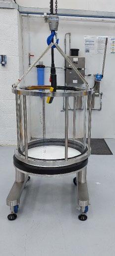
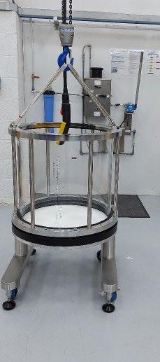
Operating Manual and Installation Guide Evolve® 600 mm Process Column 6
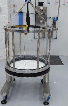
Figure 1: Evolve® 600 mm Process Column
Technical Data
*A shorter bed height can be achieved but bed height would be below flange and not visible.
Weights and Dimensions
* Based of liquid with SG of 1.05
** Minimum height needed to remove adjuster out of column unit
Operating Manual and Installation Guide Evolve® 600 mm Process Column 7
Product Code AB600505 Tube internal diameter (mm) 600 Cross Sectional area (cm2) 2828 Maximum Bed height (mm) 460 Minimum Bed height (mm) 50* Max Column Volume (L) 130 Adjustable Capacity (L) 121 Pressure rating bar psi 3.0 43.5 Operating temperature 2-30 °C Bed support pore size 10 µm
Product Code AB600505 Adjuster Weight (kg) 160 Total Weight empty (kg) 370 Total Weight Full* (kg) 513 Maximum Diameter (including casters or feet, mm) 820 Maximum height (mm) 1700 Minimum Clearance** (mm) 1850
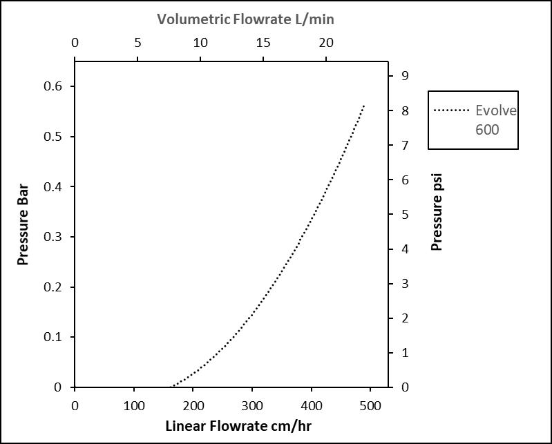
Pressure Drop
The pipework and column contribute to the pressure drop of the chromatographic system. Measuring the pressure drop from the column inlet to the column outlet shows the contribution made by the column hardware. The tests were performed at ambient temperature 15-20 °C using DI water.
The column was set at a bed height of 20 cm and filled with DI water. No bed supports were fitted to the column.
Operating Manual and Installation Guide Evolve® 600 mm Process Column 8
Figure 2: Pressure Drop Evolve® 600 mm Process Column.
Material Conformity
All materials in contact with the process stream have been selected for their suitability for use in equipment utilised in Biopharmaceutical applications and so either conform to relevant sections of FDA code of Federal Regulations vol. 21 170-199 and/or passed USP class VI test for in vivo toxicity.
Materials of construction – process-wetted parts
Column Component
Column tube
Adjuster flow tube & adaptor
Cell Flow tube adaptors (fixed)
Flow cell Inlet adaptor liner (adjuster)
Bed supports
Fixed Bed Support seal
Column tube seals
Adjuster seal
Tube Buffer Seals
Flow tube seals
Flow tube flange gasket seal
Fixed flow cell
Bottom Flange Shield ring
Adjuster flow cell
Bed support retaining ring
Bed support retaining bolt
Material
Acrylic
Polypropylene,
Polypropylene
Polypropylene
High Density Polyethylene
EPDM
EPDM
EPDM
EPDM
EPDM
EPDM
Polypropylene (black)
Polypropylene (black)
Polypropylene (black)
Polypropylene (black)
20% Glass-filled polypropylene
Sanitary clamp seals Santoprene® elastomer
EPDM - ethylene propylene diene monomer
Operating Manual and Installation Guide Evolve® 600 mm Process Column 9
Materials of construction – non-process-wetted parts
The following table lists further materials used in the construction of the column. These components are not in contact with the process feed stream. These components are manufactured from high quality materials and selected for their suitability in bioprocess environments.
Tube unit flanges
Adjuster top and back plate
Threaded central adjust rod, seal adjust tube
Seal adjust boss, seal adjust nut, seal adjust spacer
Stainless Steel
Stainless Steel
Stainless Steel
Acetal Black
Thrust bearing washers PTFE
Seal adjust handles
Lifting eye bolts
Column Base
Stainless Steel/ Acetal Blue
Stainless Steel 316
Stainless Steel 316
Foot 600 Stainless Steel with rubber pad
Casters Stainless Steel, acetal and nylon
Bolts, screws, washers, inserts
Tube unit flanges
Stainless Steel type 316
Stainless Steel
Operating Manual and Installation Guide Evolve® 600 mm Process Column 10
Material
Column Component
Chemical Compatibility
Acrylic columns are ideally suited for aqueous-based applications. See the table below for detailed compatibility information.
Resistance Resistant; suitable for continuous use
Not resistant; not recommended
Limited resistance
No information available
Notes General All solvents are at 100% concentration unless noted otherwise
Concentrations: % refer to w/w
All data is referenced to room temperature (15 – 25 ºC)
Chemical
1,2-dichloroethane
Acetic acid 25%
Acetone 5%
Acetonitrile
Ammonia aqueous <25%
Ammonium Sulphate 10-40%
Benzyl alcohol 1%
Benzyl alcohol 2%
Butanol
Calcium chloride 2
Calcium hydroxide 30%
Calcium hypochlorite
Chloroacetic acid 50%
Chloroform
Chromic acid 10%
Citric acid
Copper sulphate
Dichloromethane
Dimethyl formamide
Dimethyl sulfoxide 10%
Disodium phosphate
Ethanol 20%
Ethanol 70%
Ethylene glycol (1,2-ethanediol)
Formaldehyde 50%
Glycerol (Glycerine)
Operating Manual and Installation Guide Evolve® 600 mm Process Column 11
Non-Wetted Stainless Steel 316L
Wetted Components
Chemical Compatibility cont.
Chemical
Guanidine hydrochloride 6 M
Hydrochloric acid 10%
Hydrofluoric acid
Hydrogen peroxide
Industrial methylated spirit (IMS)
Methanol 20%
Methanol 50%
Methyl chloride (Chloromethane)
Methyl ethyl ketone (MEK)
Methylene chloride
Nitric acid 10%
Nitric acid 70%
Peracetic acid 300 ppm
Phosphoric acid
Potassium hydroxide 2 M
Iso-propanol 20%
Iso-propanol 40%
n-propanol 20%
Sodium acetate
Sodium bicarbonate 20%
Sodium carbonate
Sodium chlorate
Sodium chloride 2 M
Sodium chloride 6 M
Sodium hydroxide 0.5 M
Sodium hydroxide 2 M
Sodium hypochlorite 200 ppm
Sodium nitrate
Sodium sulphate
Trichloroethene (Trichloroethylene)
Triton® X-100 surfactant
Urea 6 M
Zinc chloride
Operating Manual and Installation Guide Evolve® 600 mm Process Column 12
Wetted Non-Wetted Stainless Steel 316L
< 55%
Safety Guidelines
The following safety guidelines are presented.
General
The safety rules in this document are intended as a guide for the safe operation of the column.
All operation and service personnel working with the equipment should be familiar with this information prior to system start up.
Evolve® Process Columns are designed and manufactured with consideration to accepted safety standards. We advise the following:
1. Ensure the maximum rated operating pressure cannot be exceeded by installing overpressure safety device(s).
2. Include over or under temperature protection devices if it is possible that temperature deviations could mean that the column operated outside the temperature range of the equipment, or where temperature deviation could present a hazard (for example freezing of process or storage solutions)
3. Ensure that no air is introduced into the column during any column operation (for example by using a bubble trap). Air inclusion is often detrimental to chromatography processes, but the column is categorised under Pressure Equipment Directive (EU)/The Pressure Equipment (Safety) Regulations 2016 (UK) on the basis that no gas is present.
Operation
1. Only qualified personnel should operate this column
2. Ensure column is correctly assembled before use
3. Take care when handling heavy assemblies and column components. Use lifting eyes and appropriate lifting equipment
4. Do not operate faulty or damaged equipment. Ensure proper maintenance and service procedures have been performed.
5. Do not operate column beyond its maximum rated pressure or outside rated temperature limits.
6. Do not dismantle the column while it remains under pressure.
7. Do not stand on any part of the column.
Operating Manual and Installation Guide Evolve® 600 mm Process Column 13
Design of Pressure Equipment
The design of pressure containing vessels has previously been governed by the European Pressure Directive 2014/68/EU. Following the EU withdrawal, Act 2018 preserves the regulations; however, the governance has passed to UK government and are covered under The Pressure Equipment (Safety) Regulations 2016. These regulations are mandatory and govern a wide range of pressure containing vessels. The design and manufacture of chromatography columns, including the Evolve® Process Columns, are affected by these regulations.
The regulations are divided into Categories and the Evolve® 600 mm Process Column has been assessed and found that it falls within Category 1, and conformity assessment module A is adopted. This relies on i nternal production controls and no notified body involvement is required.
The foundation of the assessment as Category 1 is based on the following.
• The Evolve® 600 mm Process Column is liquid chromatography columns and when used in accordance with their Operating Instructions there should be no gas e.g., air present in the columns
• The substances that will be used in the column will remain in liquid form during the entire operation at the maximum stated operating temperature.
In addition
• The maximum operating pressure is greater than 0.5 bar and less than 10 bar
• The product pressure x volume is equal to or greater than 200 bar litres.
As the unit falls within the Category 1, it bears the CE and UKCA mark and a technical file exists which includes a Risk Assessment against the Essential Health and Safety Requirements of these regulations.
Safe Lifting of Columns
Care should be taken when handling the columns. This large column and its subassemblies are particularly heavy.
All column maintenance and handling procedures should be regarded as two-person operations.
Mechanical handling equipment or manual handling aids should be utilised to safely lift or move or position the column or its subassemblies. This will avoid potential damage to the equipment and injury to personnel.
Provision is made for the use of a hoist as eye bolts are fitted to the top of the adjuster and can be fitted to the top of the tube unit.
The lifting eyes are supplied to facilitate the safe lifting of the whole column, the adjuster assembly, or the tube unit.
It is essential that good practice is adopted regarding the use of appropriate slings and associated equipment, and to ensure the safety of personnel and prevent damage to equipment.
Operating Manual and Installation Guide Evolve® 600 mm Process Column 14
It is assumed that the user has available a hoist with hook and slings.
1. Ensure the rated capacity of the lifting equipment is sufficient to lift the column.
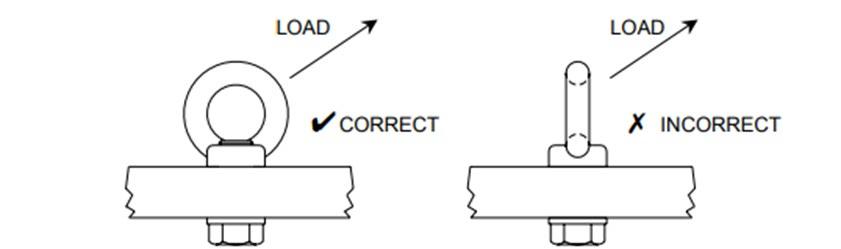
2. Ensure the lifting eyes are orientated in line with the slings. If they are not, there is a possibility of bending the eyes.
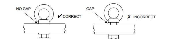
3. Ensure the shoulder of each lifting eye is in contact with the surface of the load (top plate) and the eye is securely fastened.
4. Use only one sling leg to each lifting eye.
5. Do not fit the sling hook directly to the lifting eye – use a shackle.
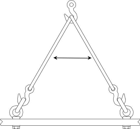
6. Ensure the slings are sufficiently long. The included angle should not be more than 60º. Slings which are too short suffer excessive tensile load, which may lead to damage to the lifting eye or the sling. As a rule, ensure the slings are longer than the horizontal distance between the lifting eyes.
These instructions are intended to supplement users’ existing lifting practices rather than replace them and should not take precedence over Company or national standards.
Operating Manual and Installation Guide Evolve® 600 mm Process Column 15
Figure 3: Orientation of lifting eye and lifting sling.
Figure 4: Correct location of eye nut on top plate of packing rig
Column Handling during Operation and Maintenance
A potential pinch point exists between the adjuster assembly and tube flange.
Labelling highlights this issue, and operators should take care to ensure that when lowering the adjuster flange, operators are clear of this area. Further advice is given in the operation and maintenance section of the manual.

Chemical Compatibility
This manual lists those substances for which the columns are compatible. If substances not listed are to be used, the user must consider their effect as the integrity and safety of the column could be compromised.
Over-pressurisation
Users of these chromatography columns must ensure that the maximum operating pressure is not exceeded. It is recommended that an over-pressurization protection device such as a Pressure Relief Valve or equivalent is utilised.
Operating Manual and Installation Guide Evolve® 600 mm Process Column 16
Figure 5: Recommended angle between lifting slings
60° maximum
Installation and Column Set-up
Installation
The column is shipped preassembled. On receipt, it is recommended to check for damage or loosening of components during transit.
Complete instructions for disassembly and reassembly can be found in the maintenance section of the operating manual.
Removal from Packing Crate
On receipt, the packing crate will be marked with instructions on which bolts and panels to remove first. These panels should be removed.
The column is heavy and correct manual handling equipment must be used to remove the item from the packing crate.
A Certificate of Quality and serial number label are attached to the box. Remove and retain the Certificate of Quality.
Within the crate there is a separate box that contains the manual and operation guide, tool kit, connection kit and spares kit. This should be located and removed from the crate and retained.
The column is transported with its feet lowered. When the column is removed from the crate the column feet should be raised to allow the column to be moved into its location using the fitted castors.
Column Preparation
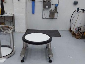
Levelling the 600 mm Columns
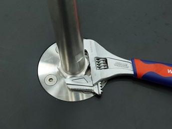
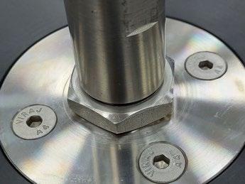
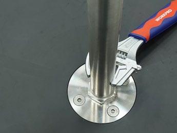
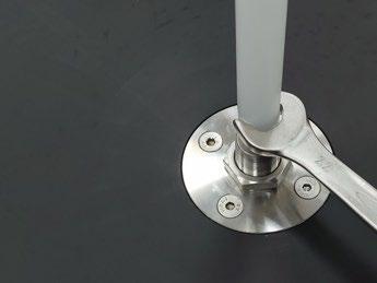
Before use, it is essential that the column is levelled. This ensures even flow and effective air removal. To facilitate this, columns are fitted with height adjustable feet and a spirit level is provided. Adjustment of the feet also increases ground clearance.
Before attempting to adjust the height of the support foot, identify the flat portion of the thread on each column foot.
1. Position the spirit level on the top of the column. Ensure the bubble is located within the central portion.
2. Turn the spirit level 90 degrees and check the level again.
3. To level the column, use the correct spanner/wrench adjust the height of the foot until the bubble is aligned.
4. This needs to be done in two directions.
Operating Manual and Installation Guide Evolve® 600 mm Process Column 17
Column Operation
This section provides general guidance on operating the Evolve® Process range of columns. It includes a hydrostatic leak test to establish that the column is installed correctly and advice for the preparation of the chromatography media.
Further advice specific to each media can be obtained from the media manufacturers; this section only provides general guidance.
Hydrostatic Leak Test
The purpose of this test is to check that there are no leaks from the column and the column is ready to use.
Due to the materials of fabrication, when the column is initially exposed to pressure the column components will flex. It is important that the hydrostatic leak test is performed as outlined below following a multiple step operation.
Ensure all fixing on adjuster and fixed end are correctly located and tightened using the correct spanners.
1. Fill the column with WFI (water for injection) or high-quality water and position the adjuster at the operating bed height.
2. Ensure the adjuster seal is wetted with buffer or other suitable liquid prior to assembly. This helps ‘lubricate’ the seal to ensure correct seating.
3. Activate the adjuster seal.
4. Ensure all air is removed from the column and any connections.
5. Attach a calibrated pressure gauge to the top inlet of the column.
6. Open the valve and increase the pressure to 1 bar (14.5 psi) and close bottom inlet valve. Wait 15 minutes for the pressure to stabilize.
7. Release the pressure in the column.
8. Check and if necessary, re-apply the torque to the fixings.
9. Open the valve and increase the pressure to 3 bar (43.5 psi) and close bottom inlet valve. Wait 15 minutes for the pressure to stabilize.
10. Check and observe the column for any leakage or decrease in pressure.
11. To pass this test the column should hold pressure.
Due the nature of materials it is likely there will be a small pressure drop, however, this should not exceed 0.2 bar.
Operating Manual and Installation Guide Evolve® 600 mm Process Column 18
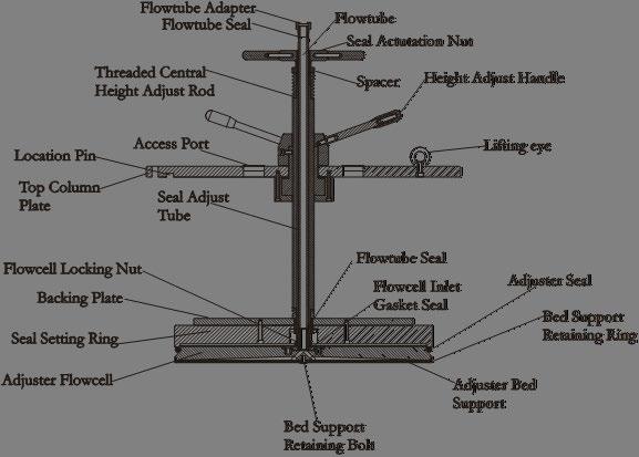
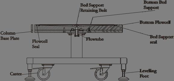
Operating Manual and Installation Guide Evolve® 600 mm Process Column 19
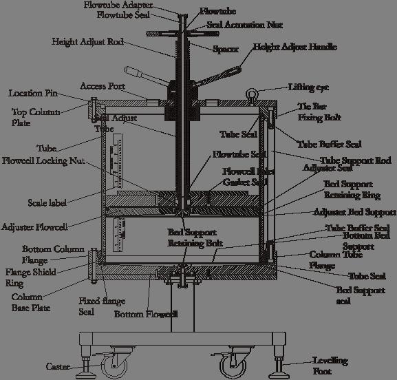
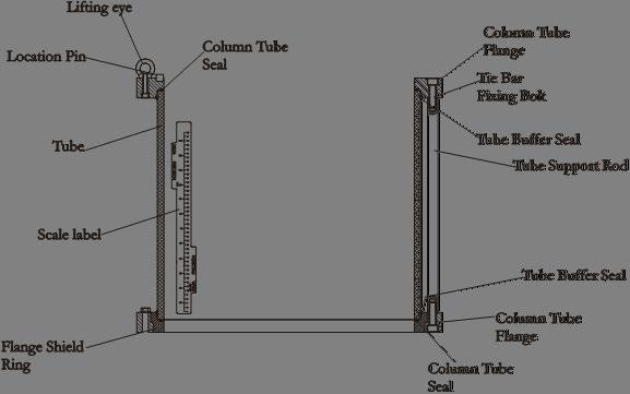
Figure 6: Schematic of the column with part identification
Example Method for Column Packing
Below provides a general method for preparing and packing the Evolve® Process Columns.
It is advisable to follow the media manufacturer’s recommendation for preparation of the media and packing the column. Ensure that any methods followed have been devised for process scale columns, as flow rates and packing pressure can vary for small diameter columns.
Media Preparation
It is advisable to follow the media manufacturer’s recommendation for preparation of the media.
General recommendations are given below:
1. The media should be prepared as a 50 – 75% slurry in equilibration buffer, packing buffer or other suitable solvent.
2. Media that contain a high level of fines will benefit from a de-fining step prior to packing. Suspend the media in a suitable buffer or solvent and allow settling to occur. Gently decant the supernatant containing the fines and discard. This may need to be performed several times.
Column Packing - Constant Flow Rate Method
1. To identify the column components, see the schematics in Figure 6.
2. Attach a valve and tubing to the outlet adaptor located underneath the column.
3. Remove the adjuster assembly.
4. Fill the fixed cell with buffer until approximately 20 mm depth of buffer is seen in the column tube. Either pump buffer into the cell via the pipe spool, or pour buffer carefully into the column, ensuring the liquid runs down the side of the tube to avoid creation of air bubbles. If buffer is poured into the column, ensure the flow cell is filled by opening the bottom process pipework and allowing fluid to exit the column. This also ensures all air has been expelled from the process pipework.
5. Ensure the valve at the fixed end is closed.
6. Ensure the slurry is thoroughly mixed.
7. Carefully pour the slurry into the column. Avoid trapping air bubbles in the slurry as it is poured.
8. Do not exceed the maximum fill limit. This is approximately 40 mm from the top of the tube. If you have slurry remaining open the bottom process port to expel some liquid from the slurry to allow further filling of the column.
9. Rinse the top inside surface of the column tube to prevent media from becoming trapped between the adjuster seal and the tube.
Operating Manual and Installation Guide Evolve® 600 mm Process Column 20
10. Set the position of the adjuster so that when it is placed into the column the adjuster cell locates above the liquid level.

11. Using a hoist and correct lifting slings lift adjuster unit into the tube unit. Alignment pins and arrow labels are located in the top flange to assist orientation.
12. Replace the adjuster assembly back into the column tube and secure to the tube flange using the flange fixing bolts. Ensure the adjuster cell assembly is approximately 30mm from the slurry mixture.
13. Attach a flexible tube to the adjuster flow tube; this tube will be used to drain excess buffer during packing.
14. Continue to lower the adjuster flow cell toward the slurry by turning the height adjust handles, but do not enter the slurry mixture.
15. The slurry will start to settle when a liquid interface is seen gently lower the adjuster in.
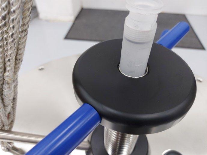
16. Set the adjuster seal using the seal actuation nut. To energize the seal, turn the handles on the seal actuation nut. Initially it may be necessary to hold the threaded height adjuster screw to prevent the flow cell from rotating. As the seal actuates the flow cell will stop rotating.
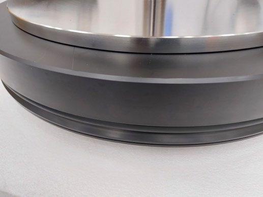
There are two methods to check if the seal has been made. It may be possible to see a witness line or contact line between the seal and the column tube, or that if the stainless steel central threaded adjust tube no longer rotates.
17. At this stage, the seal only needs to be energized so that further lowering results in buffer being forced out of the flexible tube attached to the flow tube. The adjuster unit will now be in clear buffer and packing of the media can start.
18. To fully energize the seal, turn the seal adjust nut a maximum of one revolution or until the seal adjust nut will not turn any further.
19. Ensuring that no air is introduced into the line, connect a pump and source of packing buffer to the flexible tube.
20. Consult the media manufacturer for packing recommendations. Ensure that the maximum operating pressure of the column is not exceeded; the back pressure will increase as the bed packs.
21. Pump buffer into the column at an appropriate flow rate to pack the bed. Ensure the valve at the fixed end is open. The packing flow rate should be a minimum of 20% higher than the highest flow rate to be used during the process. Some media may pack more
Operating Manual and Installation Guide Evolve® 600 mm Process Column 21
efficiently at flow rates considerably higher than the final running flow rate; refer to manufacturer instructions for guidance.
22. When no further packing of the bed is observed and the bed height has stabilized, mark the bed height and stop the pump.
23. Disconnect the top process flexible tube and direct to drain/waste
24. To lower the adjuster, turn the height adjust handles clockwise, buffer will eject from the flexible tube. If no movement is observed then gently release some of the seal compression
25. Continue downwards movement until the bed support touches the top of the packed bed.
26. If the media is compressible, the packed bed may expand while the adjuster is being lowered, and it may prove necessary to repeat steps 19 to 23 above.
27. When the final bed height has been reached, turn the seal actuation nut to apply maximum seal compression.
28. After the final compression step, flow in the upwards direction to remove any residual air at the top of the column.
CAUTION: When the column is under pressure do not tighten the seal adjust nut
Unpacking
The column may be unpacked by removing the adjuster, and media can be dug out or reslurried and pumped out of the column tube.
Cleaning and Storage
Cleaning
NOTE: Do not use abrasive cleaning materials or pads, as these may score plastic components
The extensive solvent and chemical resistance of the column components allows the use of a wide range of clean in place (CIP) solutions, including:
• Sodium hydroxide (0.5 M - 1.0 M)
• Sodium hydroxide (0.1 M) + ethanol (20%)
• Peracetic acid (300 ppm)
For thorough cleaning after use, the column should be dismantled into its component parts, thoroughly washed with detergent, and rinsed thoroughly with deionized water. The column should then be dried prior to storage.
Operating Manual and Installation Guide Evolve® 600 mm Process Column 22
Storage
For in-process storage, the packed column may be stored in any compatible solvent (refer to the Chemical Compatibility table). Choice of a particular solvent will usually be dictated by the chromatographic media; refer to media manufacturers data. Common storage solutions include 0.1 – 0.5 M sodium hydroxide or 0.1 M sodium hydroxide + 20% ethanol, both of which are suitable for long term (several months) storage with Evolve® Process Columns.
Unpacked columns should be kept in a cool, dry, dust -free location and protected from light. Exposure of acrylic column tubes to direct sunlight for prolonged periods or sterilization with ultra-violet lights may reduce the mechanical strength of the tube
Operating Manual and Installation Guide Evolve® 600 mm Process Column 23
Maintenance
Routine Maintenance Procedures - General Guidelines
Maintenance performed on a column of this size is a two-person operation.
To disassemble and assemble the columns, follow the instructions below. After reassembling the column ensure that the column does not leak by performing a hydrostatic leakage test.
When assembling/dissembling attention should be paid to:
1. Always use the correct size tools.
2. Ideally components should be at room temperature (approximately 20 °C). If not, take particular care as thermal expansion or contraction may make components fit more tightly and thus more difficult to disassemble.
3. Dismantled assemblies should be rested on a clean, dry surface.
4. Pay particular care not to damage the edge of the flow cells.
5. When unpacking columns be careful not to scratch the inside of the column tubes.
6. Be careful not to damage stainless steel surfaces by bumping, knocking or scratching.
7. Do not over-tighten components and use correct torque settings as given in this guide.
8. Good engineering practices should be followed at all times and operations carried out in an approved and safe manner.
Allen Key Set
Allen key 14 mm Adaptor & Torque Wrench
3/8" Drive & adaptor
Spanner 19 mm/24 mm AF
Spanner 22 mm/24 mm AF
Adjustable Spanner
Spirit Level
S/Driver with Wide Blade
Maintenance blocks
O-Ring remover tool
Lifting Eyes
Tie Bar fixing Bolts
Torque setting 50 Nm
Flanges bolts Adjuster and Fixed Column Feet
Flow tube, Column Feet
Seal setting tube, Lock Nut
Used to level the column
Removal of bed support retaining ring
General
Assists O-ring removal
Operating Manual and Installation Guide Evolve® 600 mm Process Column 24
used
Tool Where
Various locations
Disassembly of Evolve® 600 mm Process Columns
Disassembly instructions are provided to enable routine maintenance of the Evolve® 600 mm Process Column. These procedures enable changing of the bed support or other components in the wetted flow path
Adjuster Assembly
1. Detach any pipework or blanking cap from the top sanitary clamp adapter.
2. Remove flange fixing bolts from the top column tube flange. Retain bolts, nuts and washers.
3. Check that the adjuster seal is released by turning the seal actuation nut counterclockwise.
4. If necessary, remove the handles from the seal actuation nut if they interfere with the hoist slings.
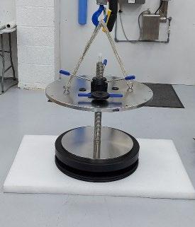
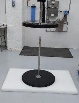
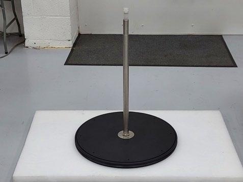
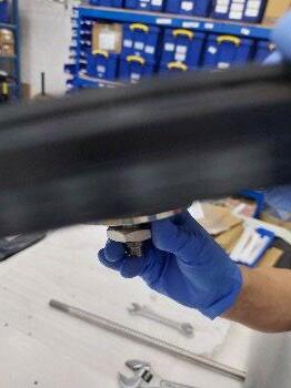
5. Using the hoist lift adjuster unit out of tube unit
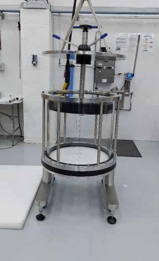
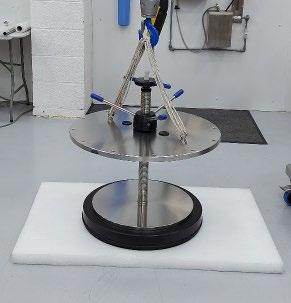
7: Photograph of Evolve® 600 mm Process Column Adjuster unit removal from column tube.
6. Move the adjuster or move the remaining column unit so access to the lifted adjuster unit is possible.
7. Place the adjuster assembly so that the flow cell face is on a suitable protective horizontal surface with the hoist still attached.
Operating Manual and Installation Guide Evolve® 600 mm Process Column 25
Figure
Identify the components as shown in schematic below, Figure 8.
(a-c):
8. Remove the seal actuation nut and spacer (Figure 9a)
9. Slowly, using the hoist, lift the adjuster flange, PAUSE the lift when the adjuster is approx. 2cm from the surface. WAIT for the flow tube, seal setting tube and flow cell to drop onto the surface.
10. Continue to lift to assembly (Figure 9b) until the flow tube is completely exposed from the threaded rod. (Figure 9c)
11. Move the remaining adjuster assembly away from the flow cell so that clear safe access is possible. Lower the remaining components of adjuster assembly onto a flat surface.
12. Ensure the flow cell is on a flat surface.
13. Undo the locking nut on the flow cell inlet (Figure 10a) and move it towards the flow cell (Figure 10b).
14. Using “flats” and adjustable spanner undo the seal setting tube (Figure 10c) and slide it upwards and retain.
Operating Manual and Installation Guide Evolve® 600 mm Process Column 26
Figure 8: Adjuster Assembly Evolve® 600 mm Process Column. a)
b) c)
Figure 9
Disassembly stages of the Adjuster Assembly
15. Remove the flow tube using the 22 mm spanner (Figure 11a and Figure 11b).
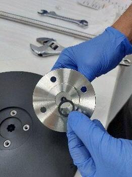
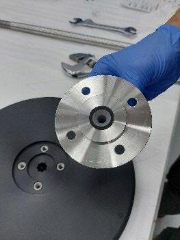
16. To exchange the cell flow tube gasket seal, locate the bolts on the rear of the flow cell. Using the correct tool remove theses bolts and retain. Lift flow adaptor and remove and replace the seal.
17. To remove the main column seal, slide the O-ring towards the edge of the seal setting ring and pull over the ring.
18. The adjuster bed support can be removed from the adjuster cell by carefully prizing the bed support retaining ring from its location groove in the side of the adjuster cell. A small extraction tool is provided. Care must be taken not to damage the retaining ring, flow cell or bed support. The central retaining bolt can be removed using the correct sized Allen key; retain this item.
Operating Manual and Installation Guide Evolve® 600 mm Process Column 27 a) b) c)
Figure 10 (a-c): Removal of Seal Adjust Tube
a) b)
Figure 11a, 11b: Removal of Flow Tube
Disassembly of Tube Assembly
The unit should only be disassembled as a part of an emergency repair procedure; specific details of the method will be provided with the replacement parts.
To access the fixed assembly, it is necessary to remove the tube assembly unit from the bottom flow cell. This unit is heavy, and a hoist should be used.
Lifting eyes for this unit are provided in the column tool kit. Refer to the safety section of this manual to ensure correct attachment and lifting procedures are followed.
1. Attach the lifting eyes to the top tube flange.
2. Remove and retain the flange bolts, nuts and washers.
3. Using the hoist and appropriate lifting slings, lift the tube unit off the bottom flow cell and place down on the floor.
4. Identify the components in the schematic shown in Figure 12.
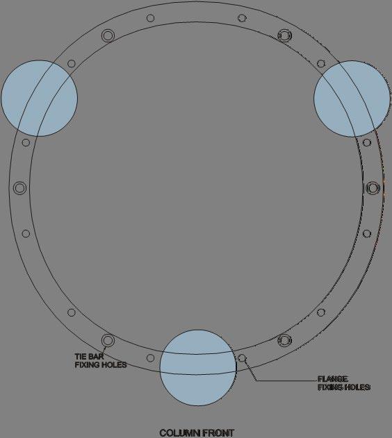
5. Attach the spare set of eye bolts provided with the original column, to the top tube flange. The correct position for these is located 2nd hole to the location pin. The hole is also recessed on the underside of the flange unlike the flange fixing bolt holes. (See Figure 13).
Operating Manual and Installation Guide Evolve® 600 mm Process Column 28
Figure 12: Tube Assembly Evolve® 600 mm Process Column.
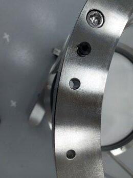
Location pin
Lifting eye fixing hole, 2nd hole from location pin on tube flange
6. Using appropriate lifting slings or equipment attach the hoist to the eye bolts.
7. Place the maintenance blocks on the floor. These should be spaced to support the bottom flange and equally spaced (Figure 14)
Operating Manual and Installation Guide Evolve® 600 mm Process Column 29
Figure 13: Position of lifting eye fixing points on column top flange.
Figure 14: Maintenance block position to support the column tube unit.
Disassembly of Fixed Assembly
1. To assist it is recommended that column feet are lowered to provide a stable base.
2. Identify the components on the schematic shown in Figure 15.
3. To replace the fixed end bed support or the bed support seal, remove the central bed support retaining bolt.
4. When replacing O-ring seals ensure the correct seal is fitted, not twisted, and correctly seated within the O-ring groove.
5. To remove the flow cell from the column base, use the correct Allen key and locate the four bolts that secure the fixed flow cell to the column base unit. Remove these bolts and retain.
6. Slide the bottom flow cell to one side. This makes it easier to lift the flow cell.
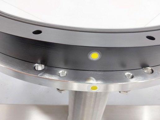
Figure 16: Displaced bottom flow cell during disassembly
7. Removing the flow cell is a two-person operation. Remove the bottom flow cell from the backing plate and place it on a clean work surface.
8. Access to the flow cell inlet gasket is achieved by inverting the flow cell and removing the flow tube adaptor bolts and remove the adaptor.
Operating Manual and Installation Guide Evolve® 600 mm Process Column 30
Figure 15: Fixed Assembly Evolve® 600 Process Column.
Reassembly of Evolve® 600 mm Process Column
Reassembly of the column is the reverse of the disassembly procedures and starts from the base of the column upwards.
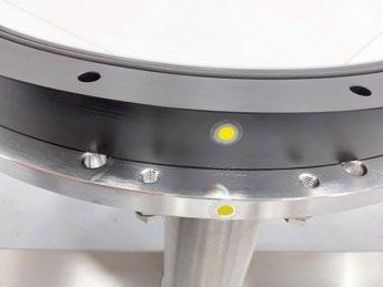
Alignment indicators are attached to the top flange, tube flanges, bottom flange and base plate to assist with the reassembly of the column and ensure correct orientation of components.
Alignment indicators
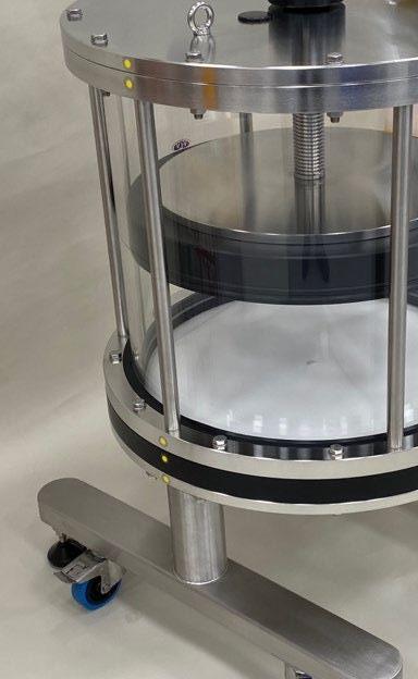
Figure 17: Alignment Indicators on Evolve® 600 mm Process Columns
Reassembly of Fixed Assembly
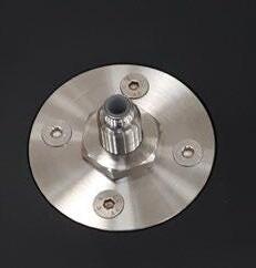
1. Place the fixed flow cell face downwards. Ensure the flow cell adaptor gasket is located and fit the adaptor by locating and tightening the bolts using the correct tool.
2. Invert the flow cell to its correct orientation.
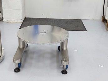
3. Lift and place the flow cell onto the base plate, use the alignment indicators to achieve correct orientation. It is recommended to place the flow cell off centre (Figure 18b), to enable operator hands to be clear.
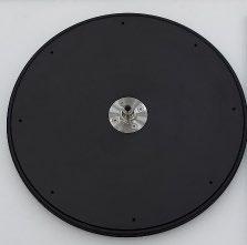
4. Locate the bed support seal into the inner most groove on the flow cell. Locate the bed support with the smooth side uppermost and secure using the bed support retaining bolt. Do not overtighten this bolt. When securing the bolt with an Allen key, ensure tool is perpendicular to bed support.
Note: Always use clean dry gloves when handling bed supports
5. Locate the column flange seal into the outer most groove on the flow cell.
6. Slide the flow cell into position. (Figure 18c), secure the flow cell to the column base plate using the bottom flow cell bolts.
Operating Manual and Installation Guide Evolve® 600 mm Process Column 31
a)
b)
c)
Attachment of Column Tube Unit
1. Using a lifting device, carefully lift the column tube unit onto the column base. Use the alignment indicators to correct align the tube unit and base.
2. Insert fixing bolts and use these to assist with alignment.
3. Lower the tube unit onto the column base.
4. Replace the fixing nuts and initially hand tighten the bolts, working diametrically opposite to ensure equal loading on the seal.
5. Using the correct spanners, tighten the bolts, working diametrically opposite around the column circumference.
6. Attach appropriate lifting slings to the eye bolts located on the tube unit flange. Lift the tube unit.
7. Move the tube unit over the fixed end assembly.
8. Before lowering the tube into place ensure the tube is orientated correctly. The correct orientation is that the scale label should be at the front of the column, perpendicular from the alignment indicators on the side of flange.
Operating Manual and Installation Guide Evolve® 600 mm Process Column 32
Figure 18 (a-c): Reassembly of Column Bottom Flow cell and base
Figure 19: Orientation of tube unit relative to alignment indicators
9. Replace the bottom column flange bolts/washers in the tube unit.
10. Slowly lower the tube uni, t and use the column bottom flange bolts to align the tube unit onto the bottom flange. (Figure 20a)
11. When tube unit is in place on column base, locate the column bottom flange nuts (Figure 20b). Hand tighten, working diametrically opposite to ensure equal loading on the seal, then using the correct spanner work diametrically opposite to tighten.
12. Remove the eye bolts from the top flange and store with other column tools.
Reassembly of Adjuster Assembly
To reassemble the adjuster unit, follow the steps as outline below:
The adjuster assembly consists of adjuster flange, seal actuation handles, threaded central seal height adjust tube and seal setting ring.
The adjuster assembly should be lifted using correct equipment and hoist slings.
Replacement adjuster flow cells are provided with the flow cell adaptor fitted. If the flow cell adapter has been removed, for example to replace the flow cell inlet gasket, then care must be taken to refit the adapter correctly.
1. Place the gasket into the flow cell inlet adapter.
Operating Manual and Installation Guide Evolve® 600 mm Process Column 33
a) b)
Figure 20a, 20b: Reassembly of Column
Figure 21: Adjuster Flow cell Inlet and Gasket position
2. To reassemble invert the flow cell and fit the flow cell inlet using the screws (see Figure 22 below). This ensures correct positioning and seating of the gasket. Ensure these screws are tight.
All handling of bed supports should be performed by a user wearing gloves.
3. Locate the bed support into the bed support retaining ring. The smooth, glossy side of the bed support should be uppermost with the coarser, dull side in contact with the flow cell. The bed support retaining ring is shown in Figure 23 as blue to highlight assembly – actual component is black.
4. Fit the bed support retaining ring and bed support to the adjuster flow cell. Working around the retaining ring, click it into position by locating the outer edge into the groove on the outside of the flow cell.
Operating Manual and Installation Guide Evolve® 600 mm Process Column 34
Figure 22: Inverting flow cell to fit flow cell inlet.
Figure 23: Orientation of adjuster bed support into bed support retaining ring
Smooth Side
Coarse Side


Retaining Ring Adjuster Flow cell Bed Support

Figure 24: Location of bed support retaining ring onto the adjuster flow cell.
5. Locate the central bed support retaining bolt and secure, initially hand tight.
6. Carefully tighten the central bed support retaining bolt using the correct tool and keeping the tool perpendicular to the bed support. Incorrect use of the tool can cause damage to the bolt and ineffective tightening.
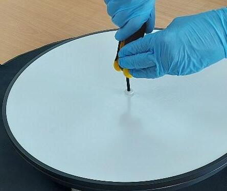
Figure 25: Tightening of the bed support retaining bolt - correct positioning of tool.
7. Turn over the adjuster flow cell and place the adjuster flow cell on a flat surface (Figure 26a) and check the flow cell locking nut is located against the flow cell (Figure 26b).
26a, 26b: Assembly stages of the Adjuster Assembly
8. Check that the flow tube seal is located in the flow tube and attach the flow tube to the flow cell inlet using the 22 mm spanner to tighten (Figure 27a)
Operating Manual and Installation Guide Evolve® 600 mm Process Column 35
a)
b)
Figure
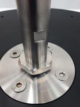
Figure 27 (a-d): Assembly stages of the Adjuster Assembly – Connection to back of Adjuster Flow cell
9. Slide the stainless-steel seal setting tube over the flow tube, and connect to the flow cell inlet to ensure that the tube is fully engaged and no manual rotation can be achieved. Tighten using adjustable spanner (Figure 27b).
10. Move the flow cell locking nut upwards so it contacts the end of the seal setting tube. (Figure 27c), tighten the seal setting tube against the locking nut (Figure 27d)
11. Ensure eye bolts are fitted to the adjuster flange.
12. Using appropriate lifting slings attach the hoist to the adjuster assembly and lift the unit high enough to allow the flow cell assembly to be fitted. a) b)
Figure 28a, 28b: Reassembly of Adjuster Assembly
13. Move the adjuster assembly over the flow cell (Figure 28a) and lower so the flow cell assembly slides over the threaded height adjust rod/seal setting ring assembly (Figure 28b).
Operating Manual and Installation Guide Evolve® 600 mm Process Column 36 a) b) c)
d)
14. Fit the spacer and seal adjuster handle; it may be necessary to remove the slinges to enable easy access. The seal adjust handle should be set so that the top of the handle is level with the top of the seal adjust tube (Figure 29).
15. Reattach lifting slings and slowly lift the assembly to about 5cm from the flat surface. Fit the adjuster seal around the perimeter of the flow cell. Ensure it is seated correctly (Figure 30), before lowering the assembly back to the surface.
Replacing the adjuster assembly into the column.
1. Attach appropriate lifting slings to the eye bolts located on the adjuster assembly. Lift the adjuster assembly.
2. Move the assembly over the column unit. Use alignment indicators to line up the adjuster. Slowly position the adjuster unit into the column tube (Figure 31a). Alignment pins are located in the top flange to assist positioning. (Figure 31b).
Operating Manual and Installation Guide Evolve® 600 mm Process Column 37
Figure 29: Reassembly of Adjuster Assembly
Figure 30: Reassembly of Adjuster Assembly

3. Locate the top flange fixing bolts/washers (Figure 31c). Hand tighten, working diametrically opposite to ensure equal loading, then, using the correct spanner work diametrically opposite to tighten fully.
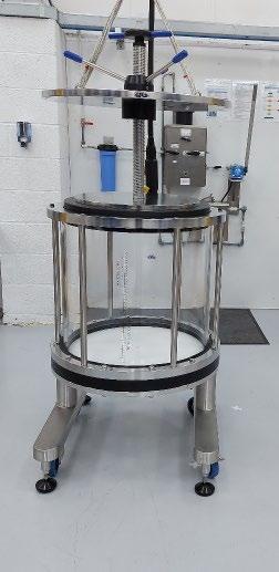
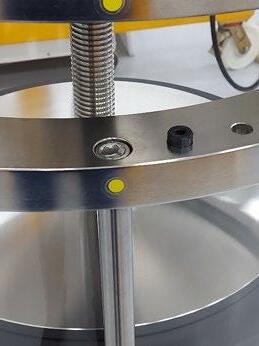
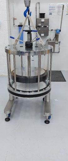
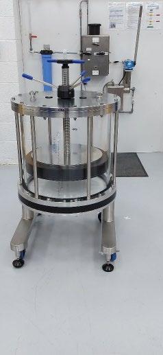
Figure 31 (a-d): Location of Adjuster Assembly completing Column Refresh Procedure
4. Remove lifting slings (Figure 31d). Column has been successfully reassembled and ready for hydrostatic leak test and return to operation.
Operating Manual and Installation Guide Evolve® 600 mm Process Column 38
b) c) d)
a)
Troubleshooting
Refer to the maintenance section before undertaking any procedure advised below.
Excessive column back pressure
When troubleshooting sudden pressure increases or decreases ensure that pressure readings are always taken at the same location so that accurate comparison can be made.
There are numerous factors that can cause excessive back pressure in chromatography, such as problems with the chromatography system (e.g., partial valve failure), issues with the media packed bed (e.g., over compression, consolidation, or bed fouling), the process fluid, or problems with the column.
Sudden decreases can result from bed collapse or cracking, flow instability or pumping issues.
This troubleshooting guide focuses solely on issues related to the column.
Possible Cause
Bed support blockages
Restrictions to inlet/outlet pipework
Incorrect seal size used to connect pipework.
Suggested Actions
Unpack and empty the column, run a pressure drop test over a range of flow rates and compare with pressure/flow curves in manual. If blockage due to viscous feed streams or media containing fines, replace bed supports
Ensure correct connections and diameter of pipework used
Ensure correct pipework seals used
Post column valve blockages Ensure valves fitted to column are correct functioning
Loss of pressure
Possible Cause
Column leakage/seal failure
Suggested Actions
Identify cause and use advice above on leakage issues and replace parts if required
Bed support integrity lost Replace bed supports
Bed support retaining ring displaced or damaged
Bed support retaining bolts displaced or damaged
Reassembly or replace as required
Reassembly or replace as required
Operating Manual and Installation Guide Evolve® 600 mm Process Column 39
Media leakage
Possible Cause
Media or high concentration of media fines not suitable for pore size of bed support.
Incorrect bottom flow cell positioning and/or tightening.
Damage to bottom or top bed support and any bed support seals
Failure of adjuster seal
Bed support retaining ring displaced or damaged
Bed support retaining bolt displaced or damaged
Air in the column
Suggested Actions
Check particle size distribution of media and ensure a defining process has been performed before use.
Unpack column and check installation of bottom flow cell and seals. Reassembly correctly using guidance in operating manual or refresh kit guide
Replace bed supports or seals as required
Check seal for damage or misalignment. Reassemble or replace as required.
Reassembly or replace as required
Reassembly or replace as required
Care should be taken not to introduce air into the column by ensuring bubble traps are used upstream of the column, media is not vigorously stirred, all connection are primed before made and all buffers are degassed
Possible Cause
Air inclusion occurs during flow packing but before adjuster lowered
Air inclusion after packed bed formed
Suggested Actions
Release adjuster seal slowly and allow air to pass adjuster seal Lower adjuster with top process port open with no restriction
Flow in reverse direction until air is removed or any dry patches become wetted. Always requalify the packed bed after this procedure
Operating Manual and Installation Guide Evolve® 600 mm Process Column 40
Leakage from adjuster seal
Possible Cause
Damaged adjuster seal
Foreign material or media trapped between seal and sealing faces on column tube, flow cell or seal setting ring
Seal not energized sufficiently
Seal not actuating
Suggested Actions
Remove seal and inspect Replace seal if damaged
Clean and inspect seal and reseat seal
Try relaxing and re-energizing the seal
Do not adjust seal actuation handle when column is under pressure
When turning seal adjust handles it is necessary to hold central threaded rod to prevent flow cell spinning.
Wet adjuster seal with buffer or suitable liquid prior to assembly. Check seal is correctly assembled and not trapped inside seal adjust ring.
Leakage from inlet/outlet of the column
Possible Cause
Incorrect installation of flow tubes and flow tube seals
damage or over-compression of flow tube seals or flow tube adaptor seals
Damage to flow tube adaptor or pipe spool from using incorrect clamp or excessive clamp force
Suggested Actions
Use operating manual or refresh kit manual to assemble correctly
Replace any damaged components
Replace any damaged components. Ensure plastic clamps are used as metal plastic can be over tightened and can cause damage
Leakage from bottom of the column
Possible Cause
Incorrect assembly during column refresh operation:
• Bed support seal not fitted.
• Column flange seal not fitted.
• Column tube seal not fitted.
• Flange bolts not tightened.
• Flow cell inlet or gasket not fitted correctly
Suggested Actions
Use operating manual or refresh kit manual to assemble correctly.
Operating Manual and Installation Guide Evolve® 600 mm Process Column 41
Leakage around seal adjust tube/flow tube for column
Possible Cause
Adjuster seal not made
Damage, misalignment or missing flow cell gasket
Suggested Actions
Ensure seal is fully energized using the seal adjust handles
Ensure correct installation of flow cell inlet gasket seals.
Operating Manual and Installation Guide Evolve® 600 mm Process Column 42
Kits, Spare Parts & Accessories
The following kits are supplied with the column:
• Tool kit, including additional eye bolt to assist in column disassembly/assembly.
• Connection Kit
• Spares Kit
It is possible to re-order these kits using the product codes listed in the table below.
This kit contains frequently used connectors and is also supplied with the column.
Operating Manual and Installation Guide Evolve® 600 mm Process Column 43
Tool kit DESCRIPTION QTY PRODUCT NUMBER TOOL KIT Allen Key Set 1 AA60TK Spanner 22 mm/24 mm 1 Spanner 19 mm/24 mm 2 Adjustable Spanner 2 Torque Wrench 3/8" Drive & 14mm Allen Adaptor 1 Spirit Level 1 S/Driver with Wide Blade 1 O-ring removal tool 1 Maintenance blocks 3 Lifting Eye and Fixings 2 Connection
kit
DESCRIPTION QTY PRODUCT NUMBER CONNECTION KIT Flow tube Adaptor, 14 mm bore 1 AA60CK Click Clamp, 3/4" Ladish 3 Flow Tube Seal, Ladish 14 mm Bore 3 Flow cell inlet gasket seal 2 Adjuster Flow tube 1 Flow tube adaptor seal 2
Spares Kit
This kit covers basis spare parts and is supplied with the column. If spare bed supports are required, please order ‘Bed Support Kit AA60BSK
Operating Manual and Installation Guide Evolve® 600 mm Process Column 44
DESCRIPTION QTY PRODUCT NUMBER SPARES KIT Adjuster Seal Evolve® 600 mm Column 1 AA60SK Bed Support retaining ring 1 Bed support fixing bolt 2 Fixed bed support seal 1 Bottom Tube seal 1 Top Tube seal 1 Fixed Flange Seal 1 Flow tube adapter seal 2
Other Spare Parts and Accessory Kits
Several kits are available to order using the product number as shown below.
This includes the Column Refresh Kit, which provides all wetted components and instructions how to exchange these components.
Assembly including tube, buffer rings, Labels (scale label, Serial No, Rating Plate, Evolve®)
Operating Manual and Installation Guide Evolve® 600 mm Process Column 45
DESCRIPTION QTY PRODUCT NUMBER COLUMN REFRESH KIT Flow Tube Adaptor 14 mm Bore 1
Adjuster Flow Tube with seals 14 mm Bore 1 Bed Support retaining ring 1 Bed support retaining bolt 2 Adjuster Seal, Evolve® 600mm Column 1 Adjuster bed support 1 Fixed bed support 1 Fixed bed support seal 1 Bottom Tube Seal 1 Fixed flange seal 1 Top Tube Seal 1 Flow Tube Seal, Ladish 14mm Bore 3 Click Clamp 3 Blanking caps 2 Adjuster Cell assembly including flow tube adaptor, Locking Flow cell nut, bolts and inserts and gasket 1 Fixed cell assembly including flow tube adaptor, bolts, inserts and gasket 1 Flange Shield Ring 1
1 Fitting Instructions 1 Other kits are also available. DESCRIPTION QTY PRODUCT NUMBER BED SUPPORT KIT Adjuster Bed Support 1 AA60BSK Fixed Bed Support 1 Bed Support Retaining Ring 1 Bed Support Retaining Bolt 2
AA60CRK
Tube
Operating Manual and Installation Guide Evolve® 600 mm Process Column 46 DESCRIPTION QTY PRODUCT NUMBER FLEXIBLE HOSE KIT Flexible Hose 14 mm Dia X 2m 2 AAFHK4 Flow Tube Seal, Ladish 14.0mm Bore 2 Click Clamp,3/4" Ladish 2 DESCRIPTION QTY PRODUCT NUMBER ELASTOMER KIT Adjuster Seal 600 Column 1 AA60EK Cell Flow tube gasket seal 2 Tube Seal top 1 Tube Seal bottom 1 Fixed Bed Support Seal 1 Fixed Cell Seal 1 Flow tube Adaptor Seal 14 mm Bore 2 Ladish Seal 14 mm Bore 2 DESCRIPTION QTY PRODUCT NUMBER TUBE REPLACEMENT KIT Tube, 600 X 570 1 AA60TRK Buffer Ring, 600 2 Scale Label, 600 1 Serial Number Label 1 Rating plate 1 Evolve® Label 1 Tube seal top 1 Tube seal bottom 1 Fitting Instructions 1
Contact Us
To view our Evolve® Process Column User guides please visit: https://www.astreabioseparations.com/resources/hardware- user-guides
For further enquires please contact: sales@astrea-bio.com
Operating Manual and Installation Guide Evolve® 600 mm Process Column 47
Revision History
A Initial release Jan 2022
B Update with further assembly/disassembly and troubleshooting guidance May 2023
C Rebranding April 2024
Operating Manual and Installation Guide Evolve® 600 mm Process Column 48
Revision Comments Date
Manual Revision Date C April 2024

Issue Date: 08 April 2024 Author Name:
QA Reviewer Name:
This product is covered by or for use under one or more patents: https://www.astreabioseparations.com/legal/patents/ All trademarks, trade names, trade dress, product names and logos are the property of Astrea UK Services Ltd. Copyright © 2023 Astrea Bioseparations Ltd. All rights reserved.
L Pepperell
T Moore
