
VERTICAL COALESCENCE
A MIXED-USE AFFORDABLE HOUSING SOLUTION FOR CHICAGO, ILLINOIS
AINSLEY LUDEMA


RESIDENTIAL CLUSTERS

FIGURE 3.1: Diagram by Author. Created using Adobe Illustrator.
Vertical Coalescence
FRONT PORCHES BACK
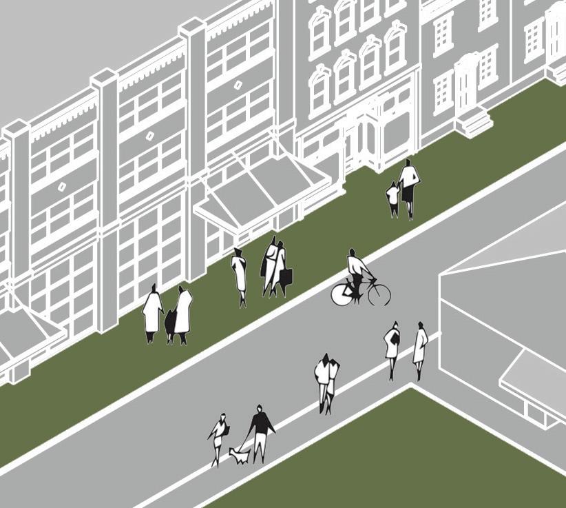


THE HORIZONTAL NEIGHBORHOOD
The neighborhood is a core aspect of this project. As Christopher Alexander said, people need an identifiable spatial unit to belong to, and these small groups create the energy and character which bring the larger community to life. Here are some of the core elements of the horizontal neighborhood, including back yards, front porches, social streets, shared amenities, and green spaces.
This project seeks to translate these patterns into a vertical format, redefining how neighborhoods can function within high-rise architecture. Shared thresholds between units, semi-public terraces, and interconnected gardens take the place of porches and yards, offering opportunities for casual interaction and quiet retreat. Social circulation paths and layered communal spaces support the same rhythms of everyday life found in low-rise communities, while adapting to the density and constraints of an urban tower. Through these strategies, the building fosters a sense of rootedness and belonging, allowing residents to identify with their floor, their cluster, and the broader vertical neighborhood as a whole.

BACK YARDS

RESIDENTIAL CLUSTERS

PRIVATE PUBLIC
FIGURE 3.2: Diagram by Author. Created using Adobe Illustrator.
Vertical Coalescence
FRONT PORCHES

SHARED AMENITIES


GREEN SPACES
THE VERTICAL NEIGHBORHOOD
These neighborhood elements manifest vertically through a series of layered, experience-rich spaces designed to support daily life. Rather than duplicating functions floor by floor, the building aims to offer a progression of communal opportunities that unfold as residents move upward. Integrated recreational zones, gardens, shared kitchens and dining spaces, small-scale retail, and nature-immersed lounges are woven throughout the structure.
Together, these spaces form a connected lifestyle ecosystem, encouraging both intentional gathering and informal encounters while reinforcing the identity of each residential group within the broader community.
SOCIAL STREETS
SHARED
CONCEPTUAL EXPERIENTIAL VIGNETTES
SUNLIGHT WIND
SOCIALIZATION
PASSIVE SYSTEMS
HUMAN INTERACTIONS
FIGURE 3.3: Diagrams by Author. Created using Rhino & Adobe Illustrator.
Vertical Coalescence
SOLITUDE FAUNA FLORA
NONHUMAN INTERACTIONS
ADJACENCIES
ATRIUM
INTERIOR GATHERING SPACE
EXTERIOR GATHERING SPACE
STUDIO APARTMENTS
1 BEDROOM APARTMENTS
2 BEDROOM APARTMENTS
PARKS
RECREATION
CLOTHING STORE
HARDWARE STORE
BODEGA
ENTERTAINMENT
CAFE/ BAKERY
ICE CREAM SHOP
RESTAURANT
BAR DAY CARE
MEDITATION SPACES
PRAYER ROOMS
FITNESS CENTER
COMMUNITY MEETING
WORK-FROM-HOME SPACES
Initial programming for this mixed-use residential design model includes an atrium, retail, residential, food, various amenities, and green spaces spread throughout. Each of these diagrams helps to identify programmatic elements and adjacencies that will be important to consider throughout the entire design process. The relationship between public and private spaces will be critical to the further development of circulation paths within. The final design aims to allow public access of interior and exterior green spaces, addressing Chicago’s lack of public green roofs. The resulting environmental high-rise will consider all of these aspects in a solution that best responds to its surrounding environment.
FIGURE 3.4: Diagram by Author. Created using Adobe Illustrator.
FIGURE 3.5: Diagram by Author. Created using Adobe Illustrator.
Vertical Coalescence
THE VERTICAL NEIGHBORHOOD
PORCHES
individual units include small balconies or recessed alcoves
SIDEWALKS
embedded interaction and recreation through meandering circulation path
COMMUNITY GARDENS
hydroponic farming spaces contribute to food security and sustainability
THE COMMUTE
work-from-home spaces provide individual desks alongside collaboration tables
FRONT YARDS
each residential cluster is accompanied by a shared green terrace
COMMUNITY CENTERS
central public spaces serve as a hub for shared activities
PARKS
multi-level landscaped atriums and sky parks serve as central gathering areas
BACK ALLEYS
discreet access points for utilities and deliveries are thoughtfully designed
THE MAIN STREET
ground level features a vibrant mixed-use space with shops, cafes, and socialization spaces
FIGURE 3.6: Diagram by Author. Created using Adobe Illustrator.
Vertical Coalescence
PROGRAM STACKING
E Van Buren St S Wabash
FIGURE 3.7: Diagram by Author. Created using Rhino & Adobe Illustrator.
Programming
TYPICAL PROGRAMMING | LAYERED
ROOFTOP PENTHOUSE
DIRECT CIRCULATION
HOUSING CONDENSED
AMENITIES AT BASE
FIGURE 3.8: Diagram by Author. Created using Adobe Illustrator.
Vertical Coalescence ROOF GROUND PLANE
CONCEPTUAL PROGRAMMING | FLOWING
PARKS, GARDENS, & RECREATION BETWEEN NEIGHBORHOODS HOUSING DISPERSED ROOFTOP GATHERING SPACE
ENCOURAGING MEANDERING CIRCULATION
DIRECT CIRCULATION BETWEEN NEIGHBORHOODS
AMENITIES SPREAD THROUGHOUT
FIGURE 3.9: Diagram by Author. Created using Rhino & Adobe Illustrator.


CONCEPTUAL DESIGN
PARTI MODELS


POROSITY


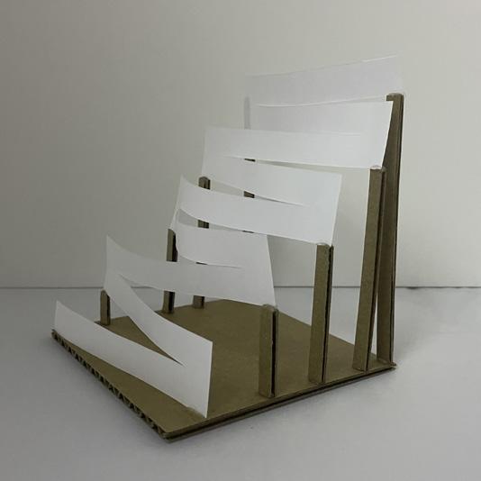
FIGURE 4.1: Images by Author. Parti models created using cardboard, paper, toothpicks, and straws.
Vertical Coalescence

STACK


HIERARCHY SLANT


CLUSTER

LAYER


CLUSTER LAYER
These finalized parti models explore the integration of natural systems and built environments within a high-rise context, emphasizing verticality, connectivity, and environmental design. They investigate how layering functions, clustering communal and
private spaces, and interweaving greenery can create dynamic, adaptable environments that encourage both individual well-being and collective identity. Through this series of methods, the resulting design promotes fluid movement, comfort, and social equity.
FIGURE 4.2: Images by Author. Concept models created using paper, clay, & matboard.
Vertical Coalescence

REACH

FLOW

LAYER + REACH
The combined parti of 'layer' and 'reach' captures the dynamic interplay between movement and extension, both within the building and its urban context. This model investigates how fluid transitions can be harmonized with intentional outreach to
create a structure that engages users at multiple scales. The resulting synthesis underscores the vision of a high-rise that not only accommodates movement but also reaches outward to embrace its urban surroundings.

FIGURE 4.3: Image by Author. Massing model created using chipboard & paper.
Vertical Coalescence
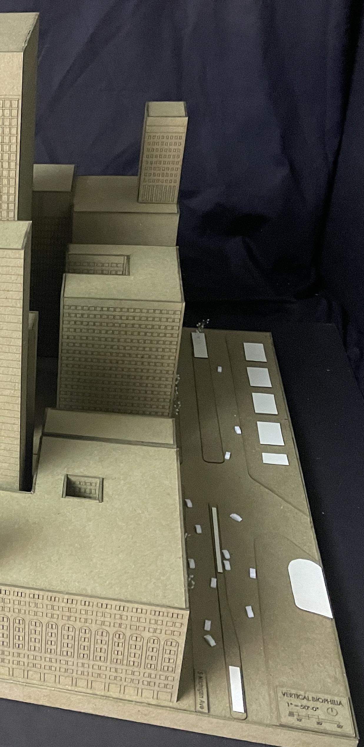
CONCEPT MASSING
This massing model displays how the combined parti of 'layer' and 'reach' interacts with the surrounding dense urban context and the adjacent elevated railway. The parti reaches outward while gesturing upward to embrace its surrounding environment.


FIGURE 4.4: Image by Author. Massing model created using chipboard & paper.
FIGURE 4.5: Image by Author. Massing model created using chipboard & paper.


FIGURE 4.6: Image by Author. Created using marker, paper, & Adobe Illustrator.
Vertical Coalescence

CONCEPT SKETCHES
Initial form-focused concept sketches explore a series of fluid architectural gestures softening the boundary between structure and landscape. Unlike rigid towers that rise in opposition to the ground plane, these concepts embrace a more continuous relationship with nature, using curvature and tapering to guide the eye (and the user) upward through a series of linked green spaces.
These forms aim to counter the alienation often felt in dense city towers by establishing an architectural language that is responsive, interconnected, and alive. The result is a structure where environmental performance and occupant well-being are supported by the very shape of the building.


FIGURE 4.7: Image by Author. Created using marker, paper, & Adobe Illustrator.
SCHEMATIC DESIGN
PROGRAMMING: DEFINING SCALES OF SOCIABILITY
COMPONENTS
• lounge
• shared kitchen
BLOCK #1 (B1) STUDENTS & YOUNG PROFESSIONALS
BLOCK #2 (B2) FAMILIES
• shared dining
• studio (a): 7 units
• studio (mr): 4 units
• 1 bedroom (a): 5 units
• 1 bedroom (mr): 2 units
• lounge
• shared kitchen
• shared dining
• 2 bedroom (a): 4 units
• 2 bedroom (mr): 2 units
• 3 bedroom (a): 2 units
• 3 bedroom (mr): 1 units
• lounge
• shared kitchen
BLOCK #3 (B3) ADULTS
NEIGHBORHOOD (N)
• shared dining
• 1 bedroom (a): 4 units
• 1 bedroom (mr): 3 units
• 2 bedroom (a): 3 units
• 2 bedroom (mr): 2 units
• B1 (x2)
• B2 (x2)
• B3 (x2)
• daycare
• play area
• quiet room
• hobby room
• multipurpose room
• dog park
• garden
• N (x2)
• park
• recreation
• gathering space
• entertainment center
VILLAGE (V)
• lending center
• library
• bodega
• restaurant
• bar
• ice cream shop
# OF UNITS OCCUPANTS (by unit)
• studio (a): 1-2
• studio (mr): 1-2
18
9
• 1 bedroom (a): 1-2
• 1 bedroom (mr): 1-2
• 2 bedroom (a): 2-3
• 2 bedroom (mr): 2-3
• 3 bedroom (a): 3-4
• 3 bedroom (mr): 3-4
• 1 bedroom (a): 1-2
• 1 bedroom (mr): 1-2
12
• 2 bedroom (a): 2-3
• 2 bedroom (mr): 2-3
78
OCCUPANTS (total)
AREA (by space) AREA (total) VOLUME (approximate)
• lounge: 500 sqft (triple height)
• shared kitchen: 400 sqft
• shared dining: 200 sqft
18-36
• studio (a): 300 sqft
• studio (mr): 400 sqft
• 1 bedroom (a): 500 sqft
• 1 bedroom (mr): 600 sqft
• lounge: 500 sqft (triple height)
• shared kitchen: 400 sqft
• shared dining: 200 sqft
21-30
• 2 bedroom (a): 700 sqft
• 2 bedroom (mr): 800 sqft
• 3 bedroom (a): 900 sqft
• 3 bedroom (mr): 1,000 sqft
• lounge: 500 sqft (triple height)
• shared kitchen: 400 sqft
• shared dining: 200 sqft
17-29
• 1 bedroom (a): 500 sqft
• 1 bedroom (mr): 600 sqft
• 2 bedroom (a): 700 sqft
• 2 bedroom (mr): 800 sqft
• B1: 8,500 sqft
• B2: 8,300 sqft
• B3: 8,600 sqft
• daycare: 800 sqft
• play area: 400 sqft
112-190
224-380
• quiet room: 600 sqft
• hobby room: 600 sqft
• multipurpose room: 800 sqft
• dog park: 250 sqft
• garden: 300 sqft
• N: 54,550 sqft
• park: 16,000 sqft (triple height)
• recreation: 8,000 sqft (triple height)
• gathering space: 8,000 sqft
• entertainment center: 5,000 sqft
• lending center: 1,000 sqft
• library: 1,000 sqft
• bodega: 1,000 sqft
• restaurant: 2,000 sqft
• bar: 1,500 sqft
• ice cream shop: 800 sqft
8,500 sqft + 40% circulation (3,400 sqft) =11,900 sqft 63’ x 63’ x 33’ (3 levels)
8,300 sqft + 40% circulation (3,320 sqft) =11,620 sqft 63’ x 63’ x 33’ (3 levels)
8,600 sqft + 40% circulation (3,440 sqft) =12,040 sqft
54,550 sqft + 40% circulation (21,820 sqft) =76,370 sqft
63’ x 63’ x 33’ (3 levels)
201,400 sqft + 40% circulation (80,560 sqft) =281,960 sqft
63’ x 200’ x 66’ (6 levels)
165’ x 200’ x 110’ (10 levels)
RESIDENTIAL | 60% AFFORDABLE park & recreation
1,002’ 73 floors
FIGURE 5.2: Diagram by Author. Created using Adobe Illustrator.
Vertical Coalescence
VILLAGE | 156 OF UNITS
NEIGHBORHOOD | 78 UNITS
PROGRAMMING: SCALES OF SOCIABILITY
As I started volumetric massing, I used a series of scales of sociability to block out square footages of interior elements. This diagram shows nine villages alongside mechanical floors, rooftop community spaces, and a parking garage in the southern structure. Each village includes two neighborhoods, park and recreation spaces, an entertainment center, lending center, library, and food options.
The next smallest scale consists of neighborhoods, each of which include six blocks alongside green spaces and more community spaces spread throughout.
Finally, at the smallest scale are blocks. These are the people residents know the very best. They’re the ones you see every day and get the most familiar with over time.
BLOCK | 9-18 UNITS
2 bedroom apartment
2 bedroom apartment
1 bedroom apartment
3 bedroom apartment
ADULTS
ADULTS - FAMILIES
FIGURE 5.3: Diagram by Author. Created using Rhino & Adobe Illustrator.
Vertical Coalescence
ADULTSYOUNG PROFESSIONALS
PROGRAMMING: BLOCK TYPES
Blocks are broken down into 3 categories to identify unit sizes applicable to residents at different stages of life. Each block consists of a triple-height lounge area surrounded by residential units. These three block-types are differentiated by the size of the units contained within, in addition to the amenities located nearest to them. Each type is scattered throughout the entire structure so that people of all stages of life live in proximity to each other.
3 block types scattered throughout:
FIGURE 5.4: Diagram by Author. Created using Rhino & Adobe Illustrator.
RESIDENTIAL | 60% AFFORDABLE
MECHANICAL FLOOR
COMMUNITY SPACE
PARKING GARAGE
RETAIL & LOBBY
GREEN SPACE
park & recreation
Vertical Coalescence
FIGURE 5.5: Diagram by Author. Created using Rhino & Adobe Illustrator.
GATHERING SPACE
LIGHT PARK
sunlight-responsive installations & reflective surfaces
WIND PARK
kinetic sculptures & open-air spaces
SOUND PARK
acoustic walls & nature soundscapes
GEOLOGICAL PARK
exposed rock formations & stone paths
TRANQUILITY PARK
dense greenery & secluded seating nooks
INTERACTIVE PLAY PARK
climbing structures & soft landscape elements
BIRD & POLLINATOR PARKS
birdhouses & pollinator-friendly flowers
GREEN SPACES: ENCOURAGING EXPLORATION
Each green space is uniquely designed, with varying scales, functions, and levels of exposure to light, wind, and sound. Some offer quiet, shaded corners ideal for reading or meditation, while others open up to panoramic views, inviting social gatherings, gardening, or even casual play. These distinct spatial experiences encourage occupants to move through the building vertically and horizontally, discovering new areas and forming a deeper, more personal connection with their surroundings.
This layered sequence of environments fosters a dynamic relationship between residents and the structure itself. Instead of confining people to isolated units or rigid circulation paths, the building invites exploration, rest, and interaction at all hours of the day. By supporting both spontaneous encounters and solitary moments, these green spaces enrich the daily rhythm of life. They cultivate a stronger sense of community, wellbeing, and belonging within the vertical neighborhood.
Schematic Design
DESIGN DEVELOPMENT
COUNTERWEIGHT
650-ton tuned mass damper
RESIDENTIAL
60% affordable
MECHANICAL FLOOR
COMMUNITY SPACE
PARKING GARAGE
RETAIL & LOBBY
GREEN SPACE
park & recreation
BASEMENT & FOUNDATION
PROGRAMMING: SECTION
Here is the programming again but in section, showing how each of these spaces are connected vertically through light wells and green spaces. This project envisions high-rise living as a dynamic, living system rather than as a static
structure. The 30’ tall green space in each village is used as the primary void for air movement within, distributed on a smaller scale to each lounge area from there.
Vertical Coalescence
FIGURE
49° AVERAGE SOLAR ALTITUDE ANGLE
BRIDGES AS PARKS
ANNUAL WIND AVERAGE:
10.5MPH FROM THE SW
30’ HEIGHT park & recreation WIND DISTRIBUTED THROUGHOUT BLOCKS FROM LARGE VOIDS
PROGRAMMING: VOIDS
Here, you can also see the bridges between the two structures taking the form of parks. The voids carved out for green spaces are connected at the center by these central light wells which are angled to capture the maximum possible amount
of sunlight throughout the entire year while avoiding excessive summer heat.
FIGURE 6.2: Diagram by Author. Created using Rhino & Adobe Illustrator.
TYPICAL SKYSCRAPER
LINEAR DIAGRID
CURVILINEAR DIAGRID W/ CHANGING SCALE
Vertical Coalescence
FIGURE 6.3: Diagram by Author. Created using Rhino & Adobe Illustrator.
DOUBLE CURTAIN WALL SECTION
operable window
raised floor
4” concrete on mtl. deck
steel beam
dropped ceiling
vertical aluminum mullion
laminated insulated fritted glass
laminated tempered glass
18” cavity
24ӯ HSS steel diagrid
ALTERING THE DIAGRID
The exoskeletal structure is designed by making two adjustments to the typical angular diagrid. First, the scale is altered to shift vertically across the façade, maintaining openness at the base and creating a visual sense of lightness towards the top. Next, the diagrid members are curved slightly to give the skyscraper a more organic and flowing presence, reinforcing its connection to natural environmental principles.
The diagrid system works in tandem with the building envelope to maximize structural performance and environmental efficiency. A double curtain wall assembly is implemented, consisting of an exterior glazed system integrated with operable panels and an interior insulated glazing system. This layered strategy enhances thermal performance, reduces energy loads, and supports passive ventilation opportunities. By coupling the diagrid’s sculptural fluidity with the precision of the double façade, the design optimizes daylighting, minimizes heat gain, and strengthens the building’s overall resilience, contributing to its sustainable goals.
CHICAGO AVERAGE ANNUAL RAINFALL: 38”
PRIMARY STORAGE TANK
2 tanks | 35,000 gallons each | 24.5’Ø x 10’
SECONDARY STORAGE TANK
4 tanks | 5,000 gallons each | 9’Ø x 10’
REFLECTION POND
collects rainwater while enhancing the microclimate
FIGURE 6.5: Diagram by Author. Created using Rhino & Adobe Illustrator.
Vertical Coalescence
WATER CATCHMENT SYSTEM
GREEN ROOF
GRAVITY-FED SYSTEM
utilizes vertical height for passive water flow
DRIP IRRIGATION NETWORK
minimizes water waste & overwatering captures & filters rainwater naturally
Here, this structure is shown in an axonometric view alongside an overview of the water collection system that helps supply water for the incorporated greenery while storing leftovers for future use. The water collection system operates through a network of concealed channels and storage reservoirs, capturing rainwater from the green roofs. This collected water supports the integrated landscape features throughout the design, including gardens, planter systems, and communal green spaces. Surplus water is stored for irrigation during dry periods, reducing the building’s dependence on municipal water supplies and promoting sustainable resource management. Together, the structural system and water strategy reinforce the project’s commitment to environmental stewardship and occupant well-being.


Vertical Coalescence
FIGURE 6.6: Image by Author. Created using Rhino, Lumion, & Photoshop.

As visitors approach the structure from the southeast, the experience of entry is framed from the intersection of E. Van Buren Street and Wabash Avenue. From this vantage point, the fluid form of the skyscraper is revealed, with floor plates reaching toward one another at each park bridge. Design Development
FIGURE 6.7: Image by Author. Created using Rhino, Lumion, & Photoshop.

Vertical Coalescence
FIGURE 6.8: Image by Author. Created using Rhino, Lumion, & Photoshop.
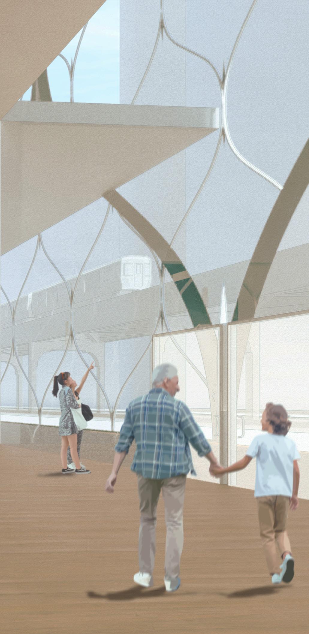
VIEW OF THE RETAIL & LOBBY SPACE
Upon entering the building, visitors are welcomed into the ground-level retail and lobby space. This vibrant threshold blends exterior and interior realms, establishing an inviting atmosphere that supports both daily routines and spontaneous interactions. This space, flooded in daylight and activity, daylight, immediately reinforces the building’s environmental principles, creating a sense of arrival that is both energetic and restorative.