13 minute read
Finishing/sizing group with agc system


edited
by: A. Nardini, E. Colombo, D. Biagini, J. T. Da Silva
The uses of long quality products (SBQ) increasingly require high metallurgical properties and excellent tolerances. Their rolling is therefore a fast process that requires high speed control and communication capabilities, with fast response electromechanical-hydraulic control systems. To offer high process stability, POMINI Long Rolling Mills has developed a finishing/sizing unit equipped with an AGC (Automatic Gap Control) system for the automatic control of the gap between the rolls, able to dynamically maintain the required dimensional tolerances. The finishing/sizing unit is placed at the end of the continuous train and consists of two vertical and horizontal two-roll stands. To control the size of the bar, the AGC system manages the dynamic positioning of the rolls, whose light variation is applied by means of synchronous screws operated by a hydraulic servomotor with proportional valve. With the finishing/sizing unit enslaved to the AGC system, a minimum tolerance of 1/5 DIN for round bars can be obtained. The same system is applicable, with the applicable changes in the product characterization, even with flat bars, for which a minimum tolerance of 1/4 DIN can be obtained.
KEYWORDS:
Introduction
HYDRAULIC POSITION CONTROL, AUTOMATIC GAP CONTROL, FINISHING SIZING STAND GROUP, AGC CONTROL
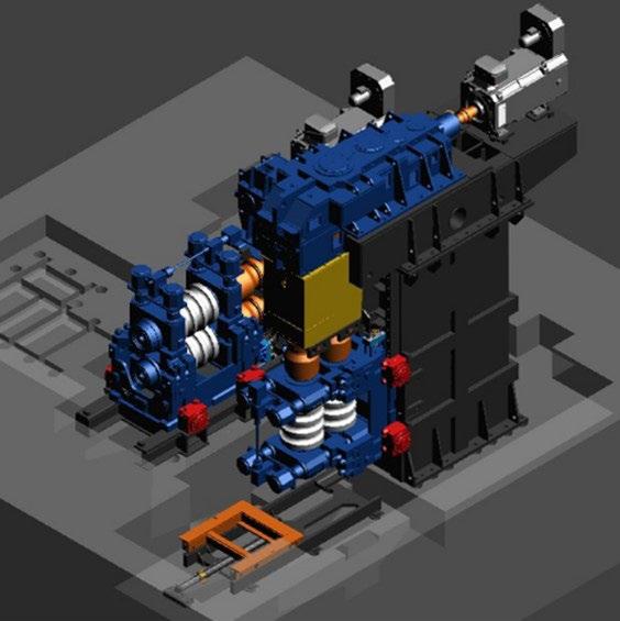
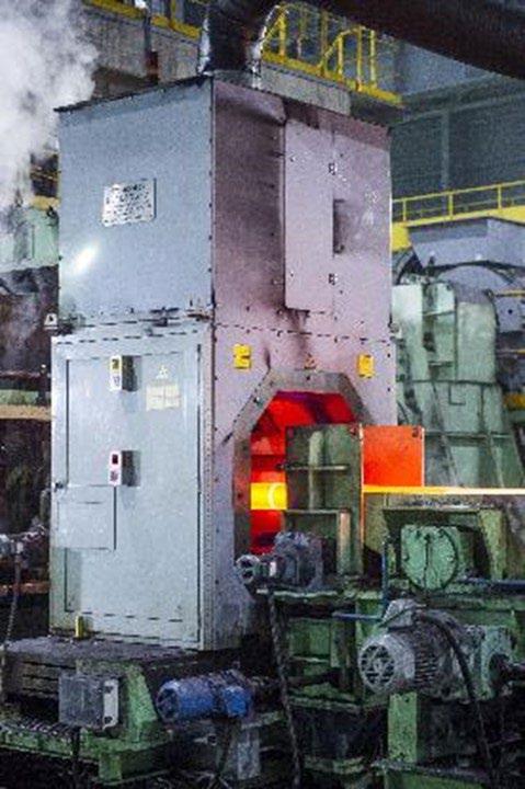
In the steel industry, the production of a SBQ rolling mill, for smooth bar and flat profile, calls for high accuracy in the product specification and high stability of the process. The bar rolling is a fast process which requires high-speed control and communication capabilities, thus the control objects are electromechanical and hydraulic systems with fast response. With the technological and industrial development, the requirements for high-quality profiles in terms of tight tolerances and metallurgical properties are becoming critical. A finishing sizing group composed by 2-rolls finishing stands (Vertical + Horizontal) is considered.
This technology is the most important mechanism for dynamic thickness control in conventional rolling mills. Since the AGC system is responsible for maintaining the dynamic performance of predicted quality dimensional tolerances, it is designed to suppress the disturbances during the rolling process such as hardness and temperature fluctuation of the bar typically during head/tail passing through.
The extremely sophisticated algorithms are developed to fulfill the task of dynamic thickness and width for a flat or ovality control for a round section, however, the philosophy and the principles for tuning AGC control gains become very complicated and difficult to the operators in the case of improving the quality for specific product and process.
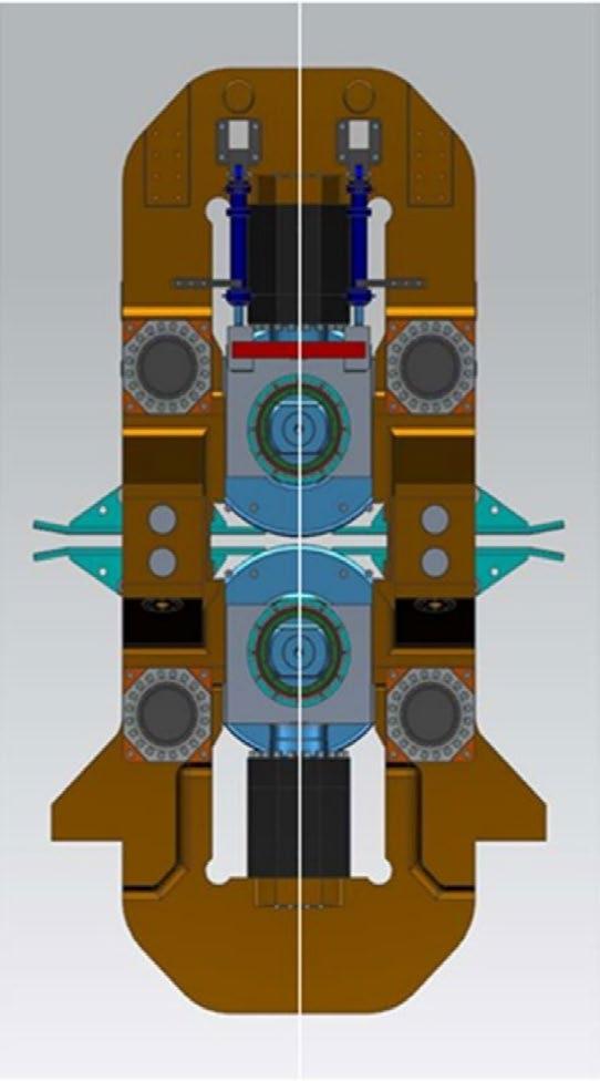
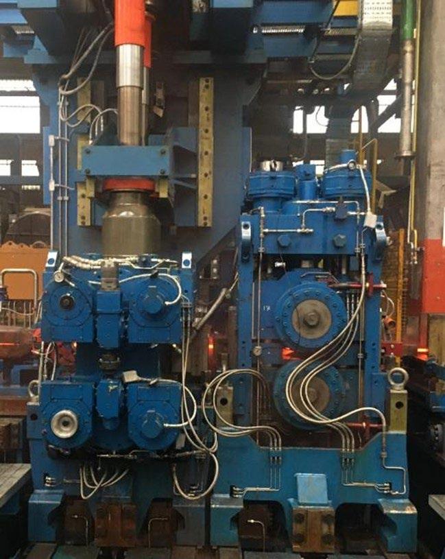
The schematic arrangement of the sizing mill is shown in Figure 1. The mill stand consists of a housing-less stands containing two cylindrical work rolls, which perform the reduction in the two directions vertical and horizontal consecutively. Gap control includes the control for the top and bottom mounted rolls by servo hydraulic motor driven through synchronous screw-downs and manage with a proportional valve. These actuators are controlled as required to support roll change, bar rolling and mill testing. The stand can be also unlocked from the left to the right side in order to be able to control independently the two sides.
The size of the steel is controlled by dynamic roll positioning. Because the reduction of hot steel in the roll bite is sensitive to mill speed changes as well as temperature and hardness changes in bar entry, the gauge control must be able to control to the desired bar size in the face of these disturbances. This control involves the careful coordination of a number of strategies. The rolls are positioned prior to entry bar of the mill in base a fixed receipt saved in level 2. It involves predictive models of the steel- rolling process, which will give accurate rollposition settings. To produce output bar of the desired dimensions, the roll position is then altered during rolling of the bar. This dynamic roll positioning during rolling is referred to as automatic gauge control (AGC). The results of rolling each bar are further analyzed and used as adaptive corrections to the predictive models.
The success of the sizes control depends on the ability of these various facets of the control to blend in a cohesive system. This blending is particularly evident in the successful development of the absolute, or predicted, mode of automatic gauge control. This mode of control involves an intimate connection between the traditional mill setup and AGC functions. Here it can be seen that a structured system design approach is necessary to ensure the proper integration of the various components of the dimensions control.
Architecture Of Automatic Gap Control System
The sizing stands group is also composed with the presence of two profile measurement gauges. One of these devices, located at the exit of the final stand, accurately measures the size dimension in a distance from the mill and therefore gives a delayed measurement of the bar sizes. Feedforward AGC is provided to help compensation for known incoming product variations. To upgrade the feedforward AGC functionality, another measurement device is being added in the entry position of sizing group in order to correlate the final exit dimension to the entry feedstock. The measurement gauges assist the AGC algorithm as it, cannot completely correct gauge due to factors such as different material spread due to different rolling temperature and tension control along bar.
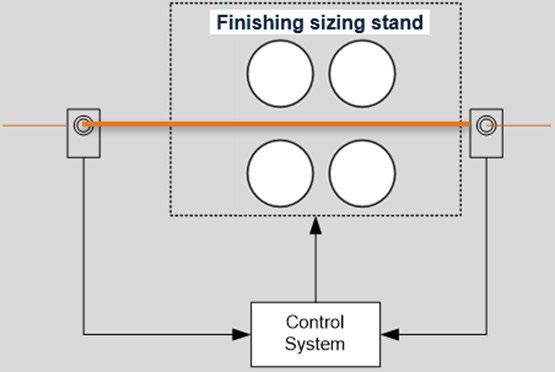
Fig.3 -Concept control of measurement gauge.
The Measurement Technique
The moving bar passes through the gauge head. Four independent optical modules allow for a continuous line of laser light to be projected around the section being measured. The camera, mounted at an oblique angle to the laser constantly see the complete profile illuminated by the laser line, enabling full dimensioning of the product. The system is based on optical triangulation principle and structured light.
Fig.4 - Measurement gauge.
The gauge head is the working heart of the system. It is a unique combination of state-of-the-art precision optoelectronics and rugged engineering. This measurement data is transferred from the optical assemblies by a fiber optic link and fed into the operator workstation by a dedicated network. The product temperature is measured by an infrared scanning pyrometer, and the system processor computes the cold size. To protect the opto- electronic system from its harsh working environment, the gauge head is both water cooled and air purged, and speedy off-line maintenance is achieved by incorporating a trolley into the main gauge body allowing the gauge to be removed from the line. In case of twisting, the measuring gauge can evaluate the twist angel (α).
Since final dimensions are the result of two rolling, the installation of an additional measuring gauge between the two stands or the implementation of a virtual sensor for groove wearing would be useful to get in time the real value of spread due to first sizing stand. AGC can adjust the stands even without this equipment, but they can be useful to change the gap of first sizing stand, avoiding any not necessary correction on last one.
Model Of Automatic Gap Control System
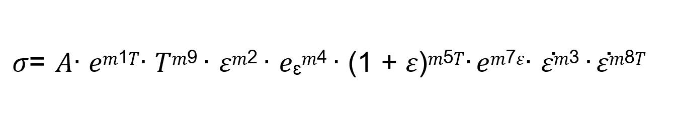
Core of the AGC is the algorithm which ensure to foresee the dimension at the exit of both sizing stand, thus is necessary to know exactly the lateral flow of the metal in the roll gap (called spread). Starting model is the HenselSpittel equation
(Eq.01)
The original formula has been modified by POMINI Long Rolling Mills thanks to know how gain with several decades of experimental parameters. The final version of algorithm collects many added variables in a formula that can be summarized in the following form: (Eq.02)
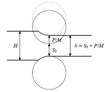
In order to predict the dynamic variation of delivery dimensions under the correction of roll gap from AGC system, a control model is utilized to calculate the consequent effects of roll gap variation on the profiles. In this section, firstly, equation and its linearized model are introduced. And then, for the purpose to simplify the structure of the simulation system, two main control algorithms of the AGC control system are taken into account, and the corresponding mathematical models are also introduced. The gaugemeter equation (h = S0 + P/M, see Figure 5) uses gap position and rolling force to estimate exit sizes of each stand. In Figure 3, before metal enters the roll bite the effective roll gap is equal to the setup gap position, S0. When metal enters the roll bite, force builds up and the mill stretches causing the effective roll gap to open. In the gaugemeter equation P/M is the amount of the mill stretch when a roll separating force is applied. Exit thickness is therefore equal to the unloaded gap position plus the stretch.
Fig.5 - Geometrical Rolling parameter.
The amount that the mill stretches is not actually linear as suggested in the above gaugemeter equation. The amount of stretch is a combination of stretch in the mill housing and deflection in the roll barrel. The mill housing stretch is typically non-linear at low forces and becomes nearly linear with force at high forces. Roll deflection is typically linear with force but varies significantly as the bar section changes.
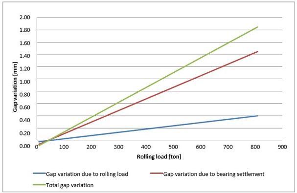
Figure 6 show the relationships between gap position, mill stretch and section sizes considering both the variation due to bearings settlement and the stand spring load.
To also validate the behavior of each side if single stand is installed an electric transducer to check the real correlation between encoder gap for screw and capsule position.
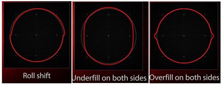
Fig.6 - Gap variation vs rolling load and bearing settlement.
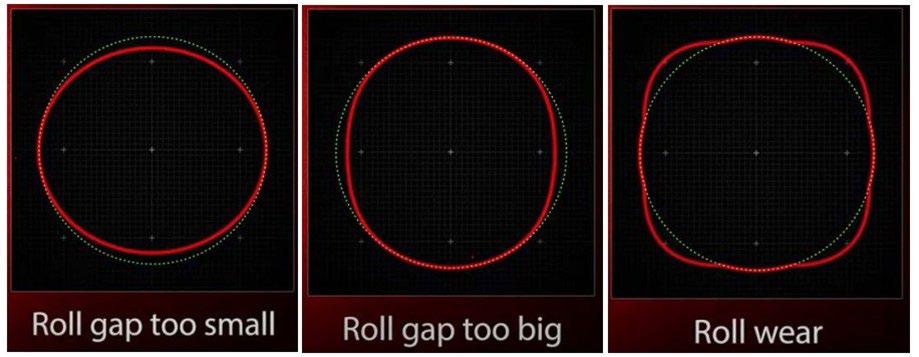
Fig.7 - Shape defects.
If measured exit profile needs a light correction, the easiest and fastest way is the hydraulic pre-set adjustment, looking for the optimum value in a predefined range that is charged in the AGC database recipes. Hydraulic unit main purpose is to increase stand stiffness, avoiding that rolling loads may relax the whole structure, ensuring a minimum clearance according to the aim of 1/5 DIN for rounds and 1/4 DIN for flats. Stands mechanical characterization (as a unique body composed by rolls, bearings, shafts, screws, …) has been developed not only with a dedicated structural Finite Element Model but also with several calibration tests: the results of these tests allowed to foresee the effect of hydraulic adjustment on the stiffness. The mathematical model to evaluate the rolling loads has been carried out on the base of Hensel-Spittel equation of stress (Eq.03) as for the spread equation, POMINI Long Rolling Mills developed the original model modifying the experimental parameters. As for POMINI Sizing Group stand version, the hydraulic pre-load adjustment is allowed during rolling if software receive an alert signal from the electric transducers installed in each side of single stand. Both for rounds and flat the analysis requested as main input the steel grade, the entry speed and temperature conditions, the draught. Even if each steel family has an own pressure setup, the equations used to describe the correlation among characteristic dimension of incoming bar, rolling loads, hydraulic pressure and shape deformation can mainly be considered similar. Representing on a chart the link between the diameter of bars and the hydraulic pressure required, it appears that the behavior derived can be generally described with a linear equation: the graph below (referred to a spring steel) shows an example.

Fig.8 - Pressure Hydraulic setting, example for Round family Ø 47-95 mm.
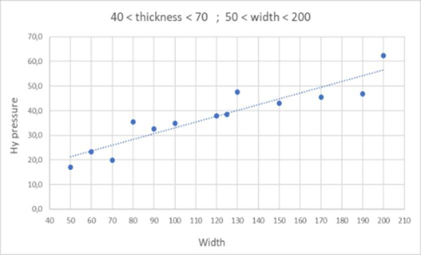
While the “characteristic dimension” used to build the mathematical expressions for round is obviously the diameter, for flats a such easy approach was not possible and then they required a further development, looking for the best combination among the variables (steel family, width, height) and using a different approach between first and second sizing stand. As is shown by the following two charts, the equations for first and second stands have a different rank and even the “characteristic dimensions” used to approximate in the best way the behavior are not the same.
Fig.9 - Characteristic dimensions setting, example for Flat range family.
Another action to get the correct exit dimension is the tension control between the two sizing stands: usually, in a continuous mill the rolling material must be flow among the stands in such a way that no deformation take place due to tension introduced by “not properly managed” rolling speed. Under specific conditions, AGC can define for the first sizing stand a different rolling speed respect the nominal value, managing correctly in the upstream continuous mill but not changing anything for the second stand. This not-adaptation is required to get a very small deformation that cannot be obtained by modifying the hydraulic settings, because it involved the whole section and not only one axis. A dedicated Finite Element Model has been developed to estimate the roll / bar contact footprint and identify the relationship between the inter stand tension and bar shape variation after the first stand of sizing group. The input width changes approximately linearly until the yield strength limit of the material is reached, but if this limit is exceeded the evolution of the width changes quickly because rolling becomes unstable. Rounds did not require any analysis on “characteristic dimensions” (the diameter), meanwhile it became essential for flats.
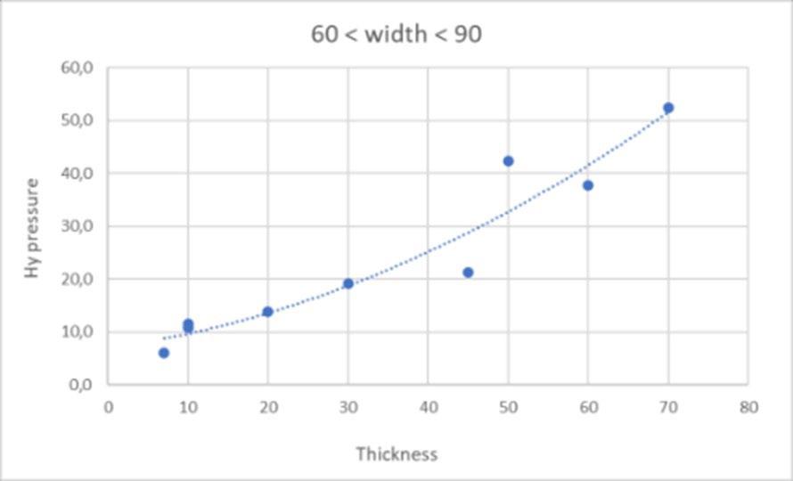
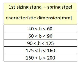
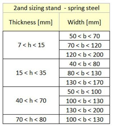
Fig.10 - Tension control effect.
If both mentioned actions (hydraulic pre-set adjustment and tension control) does not allow to obtain a finite profile within the requested ultra-precise tolerances (it may happen if the variations from the nominal parameters or groove wear conditions are considerable), also a gap correction may be requested during rolling.
If the feeding conditions are out of defined limits (either for dimensions or/and temperature), an alert appears on the dedicated pulpit screen and the AGC will be put out of order to avoid any improper series of (too) heavy corrections. It has to be intended that sizing stands will continue to roll ensuring the best tolerance according with the feeding boundary conditions, but there will not be any type of automatic setup adjustment because these wrong conditions could not lead to a uniformity in the exit sizes of the bar (thus, the system switch on manual mode).
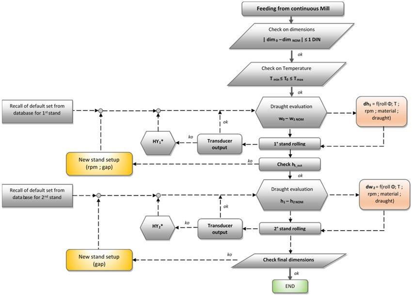
Control And Adjustment Flow Chart
AGC main way of working is represented in the following flow chart. If the feeding conditions (dimension and temperature) are within the defined limit, starting from the output measured by the gauge installed upstream, an algorithm gives the foreseen dimension at the exit of last sizing stand: if the deviation between forecast and real dimension is beyond a set limit, AGC starts an auto- tuning (this information will be stored for use it when a similar condition will occur).
If one or both electric transducers installed in each side of single stand detect an excessive strain of the structure, pre-setting working pressure would be auto adjusted on real time under rolling.
If width or height (or diameters) dimension at the exit are out of tolerances, the system introduces a gap adjustment, thus stretching arrangement will be issued if ovality were beyond the allowable limits.
Each time that the measured dimensions (width; height; diameters) are out of tolerances and a gap adjustment is required, AGC develop a series of iterative steps and at the end of each the result is compared with allowable tolerances in a close loop analysis: only the best adjustment will be tested on rolled bar.
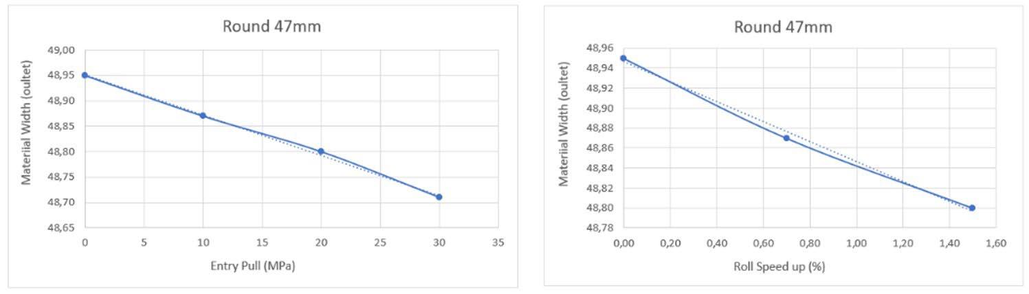
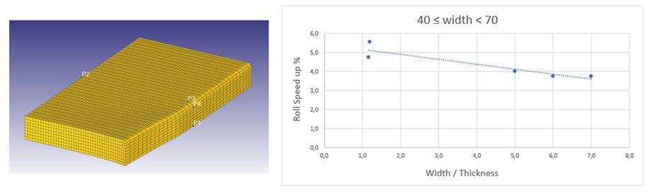
Fig.11 - AGC Logic diagram.
Application
The most important design objectives were high availability, efficient installation, optimum delivery, and ease of maintenance. A flexible modular approach was chosen to enhance these design objectives. This approach was further enhanced with the extensive use of structured design techniques.
Structured design techniques were used throughout both the hardware and software parts. The essential nature of structured design involves breaking down the complex requirements into small modules which are then easily managed. The main design effort is involved in the process of building each module and assembling them together to form the complex set of automation functions. Well structured design promotes the flexible modular approach which is significant both during the design phase and for the long-term maintenance of the system. The overall AGC software is divided into a number of individual control units, actions, and communication modules. Many of them are managed as a coordinated group of AGC functions while other functions are performed as more individual modules separate from this group.
Product data: Product dimension: Flat 60x40 mm
Rolling speed: 2.4m/s
Vertical Rolls diameter Stand 16: 477,0mm
Horizontal Rolls diameter Stand 17: 504,8mm
Steel grade: 11MnS30
Temperature: 980°C Bar length: 58 m
Fig.12 - AGC OFF Tolerance Dimension Results.
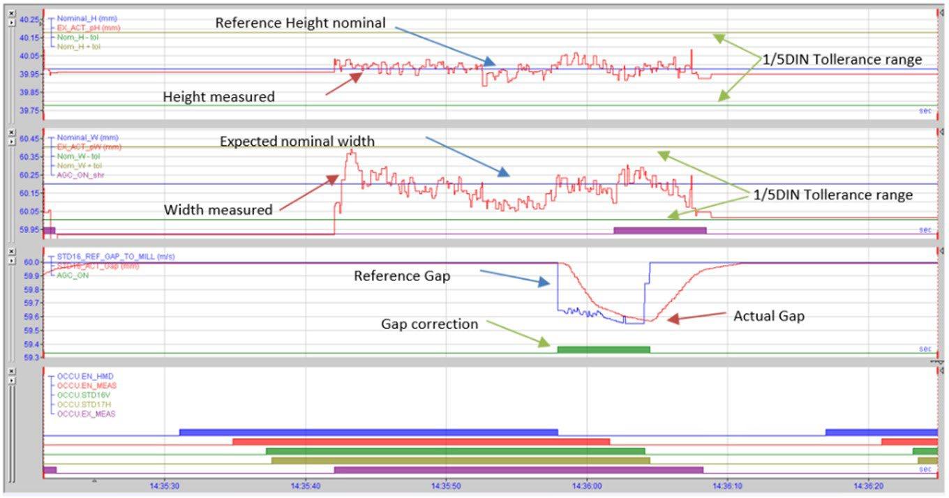
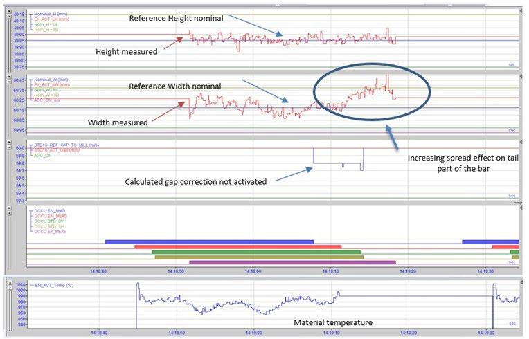
Fig.13 - AGC ON Tolerance Dimension Results.
Hmi Screen
The interface on pulpit screen has a light-weight layout because the system is working automatically, using the recipes archived and then recalled by operators from the library simply by entering the profile. The data shown on screen regards mainly the stand setting (gap reference and present, hydraulic pressure setup and loads on both sides), plus several icons that allow to know if each of general conditions are satisfied or not.
Fig.14 - Main HMI overview.
Operators can open the dedicated HMI window to check the status of AGC sequence as it follows:
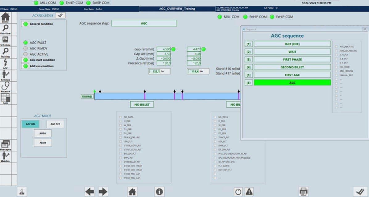
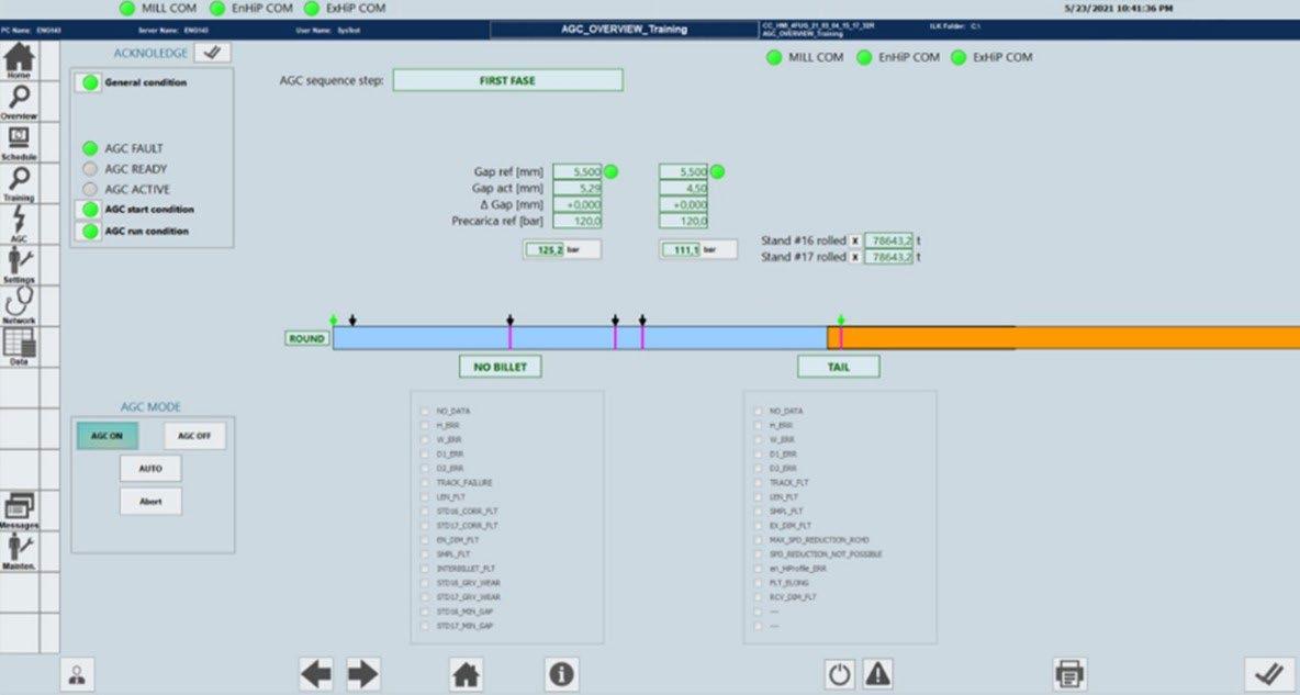
INIT
WAIT
Initial phase: AGC is not working because is switched off
AGC is waiting for the first billet (rolled in the upstream stands)
FIRST PHASE Sizing group is rolling: AGC starts to fit the matrix of parameters get while the first bar is passing through (no adaptation during the rolling)
Second Billet
FIRST AGC
Since the entry/ exit conditions and the stands setup are known by measuring systems and Level2, AGC checks if the Algorithm can be validated or a further modification of parameters is needed (if the system is confident of algorithm evaluation, automatically dummies this additional control)
The system is ready to start the correction on the incoming bar AGC System continuous running with AGC active
Fig.15 - AGC sequence detail.
Another user-friendly interface contains the setting values to be entering by operators to record the recipe. Those values are related on rolling datasheet, hydraulic and interstand setup developed by POMINI Long Rolling Mills during project analysis.
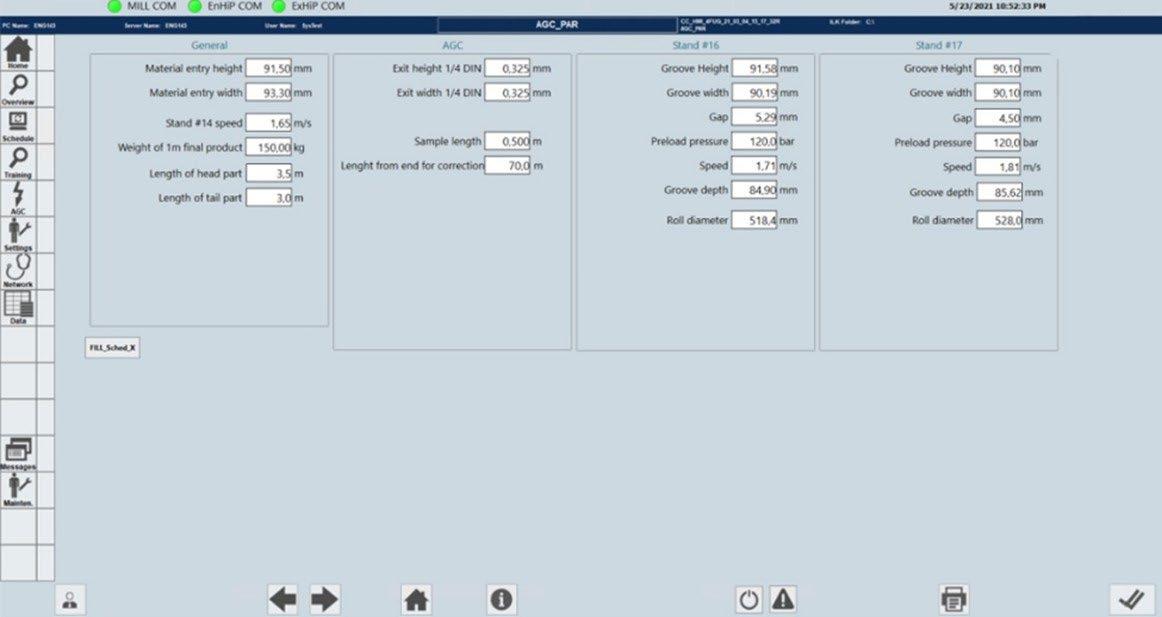
An input that will be necessary insert manually each time is the original gap when the stand assembly is completed in the workshop: the system will archive in the PLC that value, linked with the stand to be properly recalled when the stand will be inserted on mill.
Fig.16 - HMI parameter setting for AGC.
The initial settings must be adjusted not only during the hot commissioning tests, but also in the first campaign of a new profile or steel grade. If may be done updating similar recipes, operators can recall the correspondent one and easily change the parameters in the table: this procedure it’s the same used to adapt a product schedule to current conditions, and the tracking of each modification is used to record the setting change.
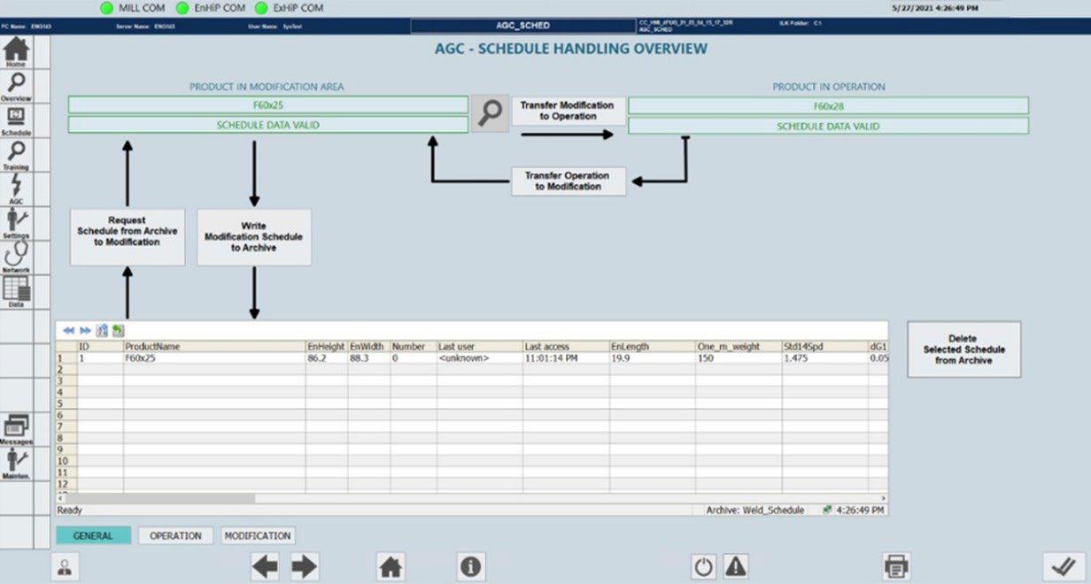
On HMI screen are designed the buttons and the arrows that can guide the operator to the modification and save of a recipe.
Fig.17 - HMI Recipes handling page.


