ProjectName Area Module
APDOPROJECT N/A N/A
ProjectNumber
JobNumber PP24-0171 SMP24-M5-30648

Pharmadule Morimatsu AB
DanvikCenter 28 131 30 Nacka, Sweden
Phone: +46(0)8 587 420 00

TheProcter&Gamble ManufacturingCompany ADD:Greensboro,North Carolina,USA
Signatures
InternalReview
Reviewedby
2 Acceptedwithcommentsincorporated.Revise& resubmit. HePeilin 2024-09-14
QAReviewby
2a ProvisionalAcceptance-Interface.Informationfrozen. N/A N/A N/A
Approvedby
3 NotAccepted.Reviseandresubmit. YanWei 2024-09-14
4 Forinformationonly Signature Date
Permissiontoproceeddoesnotconstituteacceptanceofdesign details,calculations,analysistestmethodsormaterialsdevelopedor selectedbySupplierfromfullcompliancewithcontractual obligations.
ProprietaryInformation
ThisdocumentcontainsproprietaryinformationbelongingtoPharmaduleMorimatsuABandmaynotbewhollyorpartiallyreproducednor disclosedwithoutpriorwrittenpermissionofPharmaduleMorimatsuAB.
RevisionHistory
Rev. By
01 PanWugang 2024-08-05 Issuedfor30%DesignReview 02 PanWugang 2024-09-14 Issuedfor60%DesignReview
Discipline ClientDoc.No. Rev. HVAC
DocumentType
DocumentNumber Rev.
DesignSpecification PP24-0171-T-000064 02
DocumentName Status Pages HVACDesignBrief Approved 8
1 SCOPE OF WORK
The HVAC system is to serve APDO making zone in P&G Greensboro Plant to maintain the indoor criteria Items covered are general design requirements for the supply and exhaust air handling systems that maintain the room environments.
2 CODES AND STANDARD
Design and installations are based on local US codes.
Here is a list of the code.
International Building Code (IBC), 2018
North Carolina Building Code (NCBC),2018
North Carolina Fire Code (NCFC),2018
North Carolina Energy Code (NCEC),2018
International Existing Building Code(IEBC),2018
International Fire Code (IFC),2018
International Mechanical Code (IMC),2018
National Electrical Code (NEC)
P&G Clean Design Standards:
ASHRAE - American Society of Heating, refrigeration, and Air Conditioning Engineers Standards
SMACNA – Sheet Metal and Air Conditioning Contractors National Association
3 OUTDOOR DESIGN CRITERIA
The outdoor conditions used for the HVAC system design will be based on weather data for Piedmont triad airport
Summer: DB +33.6°C [92.5°F], WB +23.3°C [73.9°F]
Winter: -7.1°C [19.2°F]
4 INDOOR DESIGN CRITERIA
4.1 TEMPERATURE AND HUMIDITY
Doc.No.:PP24-0171-T-000064
1st Floor Room 101 PAL/MAL
1st Floor Room 102 Controlled Zone Room
1st Floor Room 103
Making&Supply Tank Skid Room ≤25 °C [77°F] N/A
2nd Floor Room 101
Not Controlled
Skid Operation Platform ≤25 °C [77°F] N/A Not Controlled
2nd Floor Room 102
MCC room ≤25 °C [77°F] N/A Not Controlled
3rd Floor Spot Cooling
4.2 ROOM PRESSURE
1st floor Controlled Zone Room and PAL/MAL are designed positive pressure based on cleanness requirement and P&G Clean Design Standards
Other rooms have no pressure requirements.
4.3 ROOM CLASSIFICATION
The facility is divided into different classification areas depending on the type of work to be performed. 1st floor room 102 controlled zone room is controlled environment, 1st floor room 101 MAL/PAL is Protected envionment others room will be Standard Environment.
4.4 AIR CHANGES
A minimum air changes of 12/hour for the CONTROLLED ZONE room/MAL/PAL and a minimum of 5/hour for the first floor and MCC room.
4.5 FILTRATION
According to design basic input ,AHU should have Merv 8 pre-filters/Merv 15 final filters.
4.6 ACOUSTICAL
Noise level from HVAC sound sources shall not exceed 85 dBA at one meter from the source and should be mitigated if reasonably economical. Area
5 HVAC SYSTEMS
5.1 AIR HANDLING SYSTEM
The facilitywillbedividedinto twosystembasedon processfunction, area classification,room temperature and relative humidity requirements
One is clean air conditioning system to service CONTROLLED ZONE room and MAL/PAL
The other is comfortable air conditioning system to service MCC room, Making&Supply Tank Skid Room and Skid Operation Platform.
5.2 VENTILATION SYSTEM
The air change rate is determined by the Max requirements listed below:
Airflow needed due to equipment heat load.
A minimum 10% of outside air will be introduced to the building
Ventilation Rates Refer to ASHRAE 62.1
Input requirements from Client. Minimum exhaust (1 cfm/sf) will be provided for process area.
5.3 EMERGENCY EXHAUST
Design the Emergency exhaust system base on NFPA 400 and IMC
5.4 AIR HANDLING UNIT
The air handling unit will service to CONTROLLED ZONE room and MAL/PAL
Components listed in the direction of airflow,
Supply fan section:
Connection section including shut off damper
Merv.8 panel filter section
Elec. Pre-heater
Cooling coil
Elec.Heater
Supply fan section
Merv.15 extended surface cartridge filter section
Connection section including shut off damper
Return fan section:
Connection section including shut off damper
Merv.8 panel filter section
Return fan section
Connection section including shut off damper
5.5 EXHAUST FANS
Fans to be furnished complete with motors, wheels, drive assemblies and bearings. The fans shall be balanced and be trial run at the factory. Motor shall comply with NEC & NEMA or equivalent standards. Available power is 480V/3P/60Hz or 120V/1P/60 Hz.
5.6 FAN COIL UNIT
Fan coil units will be provided in Making&Supply Tank Skid Room at level 1 and Skid Operation Platform &MCC Room at level 2. A chilled water cooling-coil will be provided in the fan coil units to provide cooling of the air stream.
6 DUCTWORK
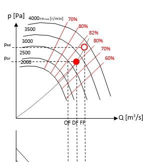
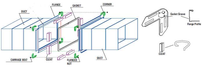
Supply, Return and Exhaust ductwork material of construction will be galvanized steel, constructed per SMACNA standard for associated pressure class. Ductwork is fabricated from G90 coated galvanized steel of lock forming grade. Ducts are joinedtogether with clamps and sealed withgaskets or sealants.Air supply to the rooms is arranged to minimize temperature gradients and air turbulence.
Flex duct, if required, shall be minimized (6’ max), vertical only,and FDA approved
7 INSULATION
Supply/Return air– Inside Exposed – Armacell AP Armaflex insulation thinckness 1 1/2” (R-Value is R-6)
8 CONTROLS
8.1 AIR HANDLING UNIT
8.1.1 GENERAL
The Air Handling Unit will operate continuously based on a start/stop signal from the Local control panel. The matched Return air fans will also operate through the Control panel and be software interlocked to the Air Handling Units supply fan.
The Air Handling Unit will be equipped with shut off damper, filter section, , cooling coil, Electrical Heater, supply fan, final filter section and shut off damper..
8.1.2 FAN START/STOP
The Air Handling Unit will be started or stopped from Local control panel.
Supply fan shall only start after all safety sequences are satisfied, smoke detectors, main room pressure switch and low temperature sensors do not indicate an alarm condition.When the system is in non-alarm condition and indicated to start, outdoor air shut off damper and supply air shut off damper opens. Once all dampers end switches prove their respective dampers open, the supplyfan shall start.
The return fans associated to the Air Handling System will operate continuously based on a start/stop signal. When the return fans are indicated to start, the return air shut off dampers shall
open. Once the return air shut off dampers end switches prove their respective dampers open, the return fans shall start.
The return fans will interlock the Air Handling Unit supply fan. Supply fan shall stop if the return fans stopped.
8.1.3
FAN CONTROL
The supply air and return air fans respective VFD shall modulate fan speed to maintain supply air, return air and circulation air duct static pressure set point.
The AHU control panel shall monitor total supply air flow.The AHU control panel shall monitor supply air and return air fans respective VFD feedback signal, status and fault signal.
Pressure differential transmitters for measuring duct static pressure are located in the supply air and return air main header ductwork.
8.1.4 COOLING COIL
A chilled water-cooling coil will be provided in the supply air Air Handling Unit to provide cooling and dehumidification of the air stream. The chilled water control valve shall modulate to maintain the return air relative humidity set point and to maintain the supply air temperature (adjustable) set point.
Cooling coil shall be controlled by the AHU control panel in sequence with heater and cooling coil to maintain supply air temperature (adjustable) set point.
High return air relative humidity has priority over the supply air temperature.
8.1.5
ELEC.HEATER
A elec. pre- heater and heater will be provided in the supply air Air Handling Unit to provide heating of the air stream. Heater shall be controlled by the AHU control panel to maintain the supply air temperature (adjustable) set point.
8.2 FAN COIL UNITS
Fan coil units will be controlled from local temperature controller. The fan coil units will operate continuously. The fan coil unit operation will be a recirculation air unit with constant air volume.
The chilled water control valve shall modulate to maintain the room temperature set point. The chilled water control valve shall close if the fan coil unit stops.
8.3 EXHAUST FANS
Exhaust fans will be controlled from local fan control panel.
Doc.No.:PP24-0171-T-000064
All 01 All
5.2 02 A minimum 10% of outside air will be introduced to the building AHU fresh air ration is 50%
5.4 02 Add a Elec.Pre-heater
8 02 (New added) N/A
Doc.No.:PP24-0171-T-000064
ProjectName
APDOPROJECT
ProjectNumber
PP24-0171
JobNumber

Pharmadule Morimatsu AB
DanvikCenter 28 131 30 Nacka, Sweden Phone: +46(0)8 587 420 00

Signatures InternalReview
Reviewedby
TheProcter&Gamble ManufacturingCompany ADD:Greensboro,North Carolina,USA
N/A
2 Acceptedwithcommentsincorporated.Revise& resubmit. HePeilin 2024-09-14 N/A
QAReviewby
2a ProvisionalAcceptance-Interface.Informationfrozen. N/A N/A N/A
Approvedby
YanWei 2024-09-14 N/A
3 NotAccepted.Reviseandresubmit.
4 Forinformationonly Signature Date
Permissiontoproceeddoesnotconstituteacceptanceofdesign details,calculations,analysistestmethodsormaterialsdevelopedor selectedbySupplierfromfullcompliancewithcontractualobligations.
ProprietaryInformation
ThisdocumentcontainsproprietaryinformationbelongingtoPharmaduleMorimatsuABandmaynotbewhollyorpartiallyreproducednor disclosedwithoutpriorwrittenpermissionofPharmaduleMorimatsuAB.
RevisionHistory
Rev. By
01 PanWugang 2024-08-05 Issuedfor30%DesignReview
01 PanWugang 2024-09-14 Issuedfor60%DesignReview
Discipline
ClientDoc.No. Rev. HVAC N/A
DocumentType
DocumentNumber Rev.
TechnicalSpecification PP24-0171-T-000065 02
DocumentName Status Pages
AirHandlingUnitSpecification Approved 14
2.9.1
1 GENERAL
1.1 DESIGN CRITERIA
Parameter
Value
Site location: Greensboro, North Carolina
Outdoor Air design criteria-Winter: DB: 19.2°F [-7.1°C]
Outdoor Air design criteria-Summer
DB: +92.5°F [+33.6°C]
WB: +73.9°F [+23.3°C]
1.2 PURPOSE
To specify the requirements for the Air Handling Units serving 1st Floor room 101 PAL/MAL and room 102 Controlled Zone room.
Air handling unit vendor shall assume single source responsibility for all Air Handling Unit components and accessories.
1.3 DOCUMENTS
Refer to vendor calculations, drawings, and equipment data sheets for component data and arrangement.
1.3.1 PHARMADULE-MORIMATSU PROJECT NUMBER AND EQUIPMENT TAG NUMBER.
1.3.2 DETAILED DRAWING, ELECTRONIC FILE
In addition, provide the following:
1. Equipment drawings showing dimensions, configuration, major component locations, access door locations, duct connection sizes and locations, section splits, shipping splits and rigging and mounting requirements.
2. Model numbers and serial numbers.
3. Materials of construction for housing and major components.
4. Motor sizes and types.
5. Details of thermal break including performance at design conditions.
6. Equipment operating weight.
7. Unit components, including filters, preheat coils, cooling coils, humidifiers, fans, etc.
8. Special support requirements.
9. Manufacturer’s nameplate details.
10. Factory and required test procedures for review and acceptance.
11. Manufacturer’s standard procedures for cleaning and packaging and written recommendations for field storage, both indoors and outdoors.
Doc.No.:PP24-0171-T-000065
Fill in and submit the vendor-data sheets or submit required information by printout from computerized selection software.
1.3.3 DESIGN PERFORMANCE
1. Absorbed motor power in kW.
2. Rated power in kW.
3. Air flow rate, CMH [CFM]
4. Total external static pressure, Pa.
5. Unit internal component pressure drops, Pa.
6. Preheat and cooling coil selections (computer calculations), including flow rates, temperatures, pressure drops, connection sizes, face velocity, fin density and number of rows.
7. Sound power levels at octave band centres.
8. Fan type, impellor type, size, class, drive arrangement, discharge/rotation, tip speed, bearings, fans horsepower including drive losses, vibration isolators.
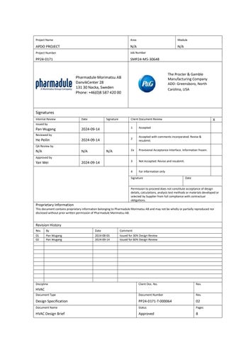
9. Fan curves shall include a series of curves indicating relationship of air flow rate to static or total pressure for various fan speeds, fan shaft power curves, fan efficiency and selection range (surge curves, maximum rpm, etc.). Indicate performance data, based on both at design air quantity (DF) and at 110% of design air quantity and 121% of design static pressure (FF), which is on the same system curve as DF. See figure 1.
Doc.No.:PP24-0171-T-000065
Doc.Name:AirHandlingUnitSpecification
OF (operational flow) is the sum of the flow supplied to the rooms served by the Air handler at design pressure.
DF (design flow) operational flow at design pressure + leakage flow.
FF (fan design flow) is at 110 % of design flow and 121% of design pressure.
1.3.4 ELECTRICAL MATERIALS
Manufacturer and model number with electrical data, wiring diagrams and accessory panel layouts.
1.3.5 COMPLETE PARTS LIST AND SPARE PARTS LIST
1.3.6 INSTALLATION, OPERATION AND MAINTENANCE MANUAL
Certified fan balancing reports shall be provided with the unit O&M manuals at the time of shipment.
1.3.7 FACTORY TEST REPORTS
1.3.8 CERTIFICATE OF CONFORMITY FOR HEPA FILTERS
1.4 TEST AND INSPECTIONS
1. Furnish materials and labour.
2. Pharmadule Morimatsu reserves the right to witness these tests.
3. Pharmadule Morimatsu may inspect unit at various stages of the construction, i.e. at completion of base, during panel erection, and prior to testing.
4. Notify Pharmadule Morimatsu five working days in advance of the testing date.
1.5 CHANGES
After a purchase is issued, changes must be:
1. Confirmed by Pharmadule Morimatsu’s change notice.
2. Shown on revised vendor drawings.
1.6 CODES AND STANDARDS
Work, materials and equipment shall meet the following codes and standards:
1. American Society of Heating and Air Conditioning Engineers (ASHRAE)
2. American Society of Mechanical Engineers (ASME)
3. International Building Code. (IBC 2018)
4. Sheet Metal and Air Conditioning Contractors National Association (SMACNA)
1.7 APPROVALS
Fabrication shall not proceed before Sign-off meeting between representatives of Pharmadule Morimatsu HVAC & Procurement departments and vendor has taken place. At the Sign-off meeting parties will agree upon technical specification for Air Handling Units and documentation/drawings/calculations from air handler and coil computer runs.
1.8 SITE INSTALLATION AND START-UP
Doc.No.:PP24-0171-T-000065
Doc.Name:AirHandlingUnitSpecification
Vendor will arrange for offloading, setting and connecting the units that are shipped in multiple sections. Manufacturer shall provide start-up assistance.
2 EQUIPMENT
2.1 ACCEPTABLE MANUFACTURE
Acceptable manufacturer: Hubber Ranner/ AL-KO or equivelant.
2.2 GENERAL
2.2.1 AHUCOMPONENTS IN DIRECTION OF AIRFLOW
Supply fan section:
Connection section including shut off damper
Merv.8 panel filter section
Elec.Pre-heater
Cooling coil
Electrical Heater
Supply fan section
Merv.15 extended surface cartridge filter section
Connection section including shut off damper
Return fan section:
Connection section including shut off damper
Merv.8 panel filter section
Return fan section
Connection section including shut off damper
2.2.2 SURFACE PROTECTION
All surfaces shall be protected against corrosion. Provide touch-up paint if necessary for field touch-up after installation of units. Internal surfaces that may be in contact with water shall be painted with epoxypaint or equal by Pharmadule Morimatsu AB approved corrosion protection.
2.2.3 NAME PLATES
Provide stainless steel nameplates permanently affixed to each unit on the fan section door. Each nameplate shall contain the following:
1. TAG number, e.g., AHU-01
2. Manufacturer’s name.
3. Manufacturer’s size and type.
Doc.No.:PP24-0171-T-000065
Doc.Name:AirHandlingUnitSpecification Revision02
4. Date of manufacture.
5. Manufacturer’s serial number.
6. Design capacity, m3/h.
7. Total static design pressure, Pa.
8. Motor data.
2.3 BASE FRAME
Base frame to be fabricated of minimum formed 12-gauge [2.05mm] steel channel, properly sized and configured to support all major components and the housing during rigging, handling and operation of the unit. The base frame may be constructed in sections as long as it is aligned and bolted. The fabricated base shall be galvanized or cleaned and painted with rust-inhibiting primer and an enamel finish in the manufacturer’s standard colour.
The base frame will be fabricated by vendor; the base frame height shall be 200 mm height. Height of base is required to provide sufficient elevation of cooling coil condensate outlet to promote condensate drainage. Provide calculations with bid documentation.
2.4 CASING
2.4.1
FRAME MEMBERS
Casing framework shall be constructed of G-90 galvanized steel Panels.
The casing shall be of a double skin construction with an adhesive-fastened insulation between interior and exterior panels of a minimum of 50 mm [2 inch] of non-combustible 50 kg/m3 [abt. 3 pounds per cubic foot] density insulation with a minimum U-value of 0.89 W/(m2K). The casing skins shall each be 0.9 mm [20 gauge] galvanized steel.
The exterior panel material and finish shall be G-90 galvanized steel with powder coating.
The interior solid sheet panel material shall be G-90 galvanized steel with powder coating.
No paint finish of any type is acceptable on the interior panels unless specified on the data sheets.
The floor shall be made in the same way as the walls.
All casing penetrations must be sealed to prevent air leakage.
Casing leakage shall not exceed three percent of design airflow at design operating conditions.
The casing shall be designed to avoid condensation at the specified temperature and humidity conditions.
2.4.2
INTERIOR FLOOR OF UNIT
Interior floor of unit in hygienic version design shall match material as with internal panel and provided an anti-slip surface on floor in each access section, securely attached to floor. Material thickness and floor construction shall be the manufacturer’s responsibility to ensure proper support of maintenance personnel without excessive deflection. To a minimum the floor shall be externally insulated to match the housing insulation. There shall be a vapour barrier on the outside face of the insulation.
2.4.3
JOINTS
Joints between panels shall be filled with an adhesive sealant to prevent the accumulation of dust and to allow wet cleaning with disinfectants.
Doc.No.:PP24-0171-T-000065
The sealant shall not provide sustenance for microbiological growth.
The sealant shall be FDA compliant.
2.4.4 MOUNTING BRACKETS
Air handlers shall be furnished with sufficient mounting brackets for cable trays on top of the unit or beside the base frame.
2.4.5
FASTENERS
All fasteners will be manufactured in material compatible to surrounding material in order to avoid corrosion.
2.5 FANS
2.5.1
DESIGN CRITERIA
Fans to be furnished complete with motors, wheels, drive assemblies; bearings and accessories as hereinafter specified.
Plug fan to be provided suitable for the performance indicated. The fan shall be selected for smooth trouble-free performance without surge, stall or excessive vibrations throughout its entire length of operation.
The fan scroll shall be heavy-duty steel, all welded construction, with side angle reinforcement. The fan wheel shall be aerofoil-type, heavy-gauge steel constructed as a single, all welded assembly. The impellers are designed for high rigidity and strength. They are balanced to an accuracy, which is better than ISO 1940-1:2003 G 6.3 at the maximum speed.
Select each fan for stable operation when controlled by VFD (Variable Frequency Drive) within the whole design operating range.
Each fan, transmission and motor combination to be capable of delivering 110% of air volume scheduled at 121% of scheduled static pressure. Normal increase of pressure-drop (for example, 100-200 Pa for filter class H10) shall be included in the design.
Consider drive efficiency in motor selection according to manufacturer’s published recommendation.
Backward inclined blades for fans.
One-speed electric motor suitable for VFD.
Fan scroll and wheel shall be cleaned, primed, and finished with the manufacturer’s standard coating prior to balancing.
Provide discharge air distributor in Air Handling Units with plug fan.
2.5.2
VIBRATION ISOLATION
Mount fan, motor and drive on an integral fan base of steel members sized to prevent distortion and misalignment of the drive and specifically sized to limit deflection of the beam on the drive side due to starting torque.
A rubber vibration isolator shall be installed between centrifugal fan casing and internal wall between the fan section and the filter section, in case additional support is necessary at start-up of the fan due to starting torque.
Connect centrifugal direct driven fan discharge to the casing by flexible connection for vibration isolation.
Doc.No.:PP24-0171-T-000065
Doc.Name:AirHandlingUnitSpecification
2.5.3
Support the fan/base/drive assembly by rigidly attached housed steel spring type isolators, with uniform loading and deflection. No bolts or holes shall penetrate the floor of the unit. Steel springs shall be designed for levelling the equipment.
MOTORS AND DRIVES
Motors shall be in accordance with electrical requirement. Mount the motor on adjustable steel base. Selection of motor shall be based on break horsepower not exceeding 90% of nameplate rating. If variable frequency drive (VFD) controllers are indicated a motor suitable for continuous operation shall be provided.
Fan drive will be direct drive type.
Electrical motors shall be NEMA MG1 type with UL listed/approved.
Electrical motors complying with 2020 National Electric Code (NEC)
Electric motors shall be 3-phase motors, 60Hz, 480V.
Acceptable Manufacturers:
TECO, WEG, Marathon or equivalent.
2.6 COILS
2.6.1
GENERAL
Hot water, chilled water coils shall be fabricated from 15.00mm O.D. seamless copper tubing with 0.85mm thick wall at a minimum.
Headers to be of the same material as tubing.
Cooling coil shall be designed for maximum face air velocity of 2.3 m/s [450 fpm] nominal (2.5 m/s or [492 fpm] max) to prevent moisture carry over. Under special circumstances, higher velocities may be used in conjunction with mist/droplet eliminator. However, the design should fully consider higher overall pressure drops.
Heating coils will be designed for maximum velocity of 3.6 m/s [700 fpm].
All connections to be copper construction, flanged connection ANSI 150# raised faced.
Select coils to prevent moisture carry-over beyond the drain pan.
2.6.2
COOLING COIL FOR CHILLED WATER
Chilled water inlet temperature is +5.56˚C [+42˚F], outlet temperature is not more than +12˚C [+53.6˚F]
2.6.3
FRAME (COOLING)
Hot-dipped galvanized steel casing, one per coil.
Service side access panel, to permit individual coil removal and replacement without disturbing other coils or piping with either cutting or welding of the unit casing, base or closure panels.
Seal piping penetrations through casing.
Coil closure panels shall prevent any air from bypassing the coils. Panels shall be of the same material as the inner liner of the unit housing.
Extend supply, return, vent and drain through the unit casing; extensions shall be sufficient length to allow proper field connections.
Doc.No.:PP24-0171-T-000065
Doc.Name:AirHandlingUnitSpecification
2.6.4 DRAIN PAN (COOLING COIL)
16-gauge 304 stainless steel, continuously welded, edges deburred.
Drain pan shall be fabricated with double slope to outlet and to be easy to clean.
Condensate pans shall be entire length of the coil and minimum 40 mm [1 3/4”] deep. Pan shall be double sloped to drain connection. Pan shall extend minimum 150 mm [6”] upstream and 455 mm [18”] downstream of the respective coil face.
Drain pan outlet shall be provided with properly sized trap in accordance with base frame height calculations.
Drain pan shall have minimum 1-1/4” drain connections.
2.6.5 HEATER
Heating is Electrical heater, heater power supply at 480 V, 3-phase, 60 Hz
2.6.6 GENERAL
Filter shall be of US standard sizes.
Air Handling Unit shall be equipped with a rigid type replaceable panel pre-filter (Merv.8)
Air Handling Unit shall be equipped with a final fine filter (Merv.15) of extended surface cartridge type, with rigid type glass fibre media.
The housing shall incorporate a positive-sealing gasket material to seal the peripheral of the filter cartridge frames, except for pre-filter.
The locking mechanism shall be of Hand-actuated Off-centre locking mechanism type.
Provide 1 extra set of disposable filters for Air Handling Unit.
Unit shall be equipped with pressure taps before and after filter section.
Maximum air velocity across filter front area is 2.5 m/s (500 fpm) at 100% of nominal airflow rate.
For small sizes where access is limited, the filter holding frame shall be withdrawable.
2.6.7 PRESSURE DIFFERENTIAL INDICATOR
Provide differential pressure transmitter to indicate the pressure drop across each filter bank.
Mount transmitter on exterior wall or on the cable tray on top of the unit adjacent to filter bank.
The transmitter will be provided by BMS contractor.
2.7 D
AMPERS
All dampers shall be accessible and of low leakage type.
Dampers shall be manufactured of extruded aluminium, multiple blade type, with interlocking airfoil blades. Individual blades shall have max length of 48”, max width of 6” and shall be mounted on plated steel axles with moulded synthetic bearings. Linkage shall interconnect all blades with one extended drive shaft for motorized or manual operator.
Shut off dampers to be equipped with electrical actuator.
Provide locking, indicating operator on volume damper, on the exterior of the Air Handling Unit.
Doc.No.:PP24-0171-T-000065 Doc.Name:AirHandlingUnitSpecification
Dampers shall be provided in a way that a single operator shall not serve more than 2.3 m² (25 ft²) of damper area.
Damper connection type will be T-24A flange connection per SMACNA standard.
2.8 CONTROLS
To be provided by control vendor.
2.9 ELECTRICAL
2.9.1
GENERAL
Provide all internal control and power wiring and equipment necessary for the operation of the Air Handling Units as described by these specifications.
All electrical equipment shall be UL listed and all electrical components and work shall conform to applicable requirements of NEMA and IEEE
Equipment and materials include the following:
Motor power connections
Conduit, boxes, and fittings
Wire and cable
Motor lead termination box
Factory-install lights, switches, conduit, wire and accessories as necessary.
Label electrical components and number wires. Seal conduit penetrations of the unit housing with clear silicone sealant. Seal conduit interior at penetration of the unit housing after wiring is installed.
2.9.2
ELECTRICAL DIMENSIONING
Internal wiring to be provided so that only following external feed is needed:
Fan power supply at 480 V, 3-phase, 60 Hz
Lighting and convenience outlets at 120 V, 1-phase, 60 Hz
Conduits shall be rigid and fixed to casing to not interfere with access.
2.10
FACTORY ACCEPTANCE TEST
All the air handling units shall be factory assembled and factory tested.
FAT Factory Acceptance Test shall include:
Type of test
Location of test
Fan and motor assembly vibration test. At supplier
Electrical test showing that electrical components are operational, motor voltage and amperage. At supplier
Unit casing leakage test with all components installed. At supplier
Doc.No.:PP24-0171-T-000065
Doc.Name:AirHandlingUnitSpecification Revision02
Fan performance tests with operating at design conditions and verified against fan curve. At supplier
REVISION LOG
2.21 02 Electrical Heater Heating coil
2.65 02
Doc.No.:PP24-0171-T-000065
Heating is Electrical heater, heater power supply at 480 V, 3phase, 60 Hz Heating coil
Project Name Area Module
APDO PROJECT N/A
Project Number
Job Number PP24-0171 SMP24 -M5-30648

Signatures
Internal Review
Pharmadule Morimatsu AB
DanvikCenter 28 131 30 Nacka, Sweden Phone: +46(0)8 587 420 00

Issued by 1 Accepted
Pan Wugang
Reviewed by
2024-09-14
He Peilin 2024-09-14
QA Review by
The Procter & Gamble Manufacturing Company ADD: Greensboro, North Carolina, USA
2 Accepted with comments incorporated. Revise & resubmit.
2a Provisional Acceptance-Interface. Information frozen. N/A N/A N/A
Approved by
Yan Wei 2024-09-14
3 Not Accepted. Revise and resubmit.
4 For information only Signature Date
Permission to proceed does not constitute acceptance of design details, calculations, analysis test methods or materials developed or selected by Supplier from full compliance with contractual obligations.
Proprietary Information
This document contains proprietary information belonging to Pharmadule Morimatsu AB and may not be wholly or partially reproduced nor disclosed without prior written permission of Pharmadule Morimatsu AB.
Revision History
Rev By Date Comment 01 Pan Wugang 2024-09-14 Issued for 60% Design Review
Document
Design Specification PP24-0171 -T-000453 01
Document Name Status Pages Air Distribution System Approved 8
1 GENERAL
1.1 PURPOSE
Specification for material, equipment and installation for air distribution system including ductwork and duct accessories.
The following documents should be studied together, in order to get a good understanding of the function and operation of the HVAC system.
Document No.
PP24-0171-T-000064
PP24-0171-T-000065
Document Type
Document name
Design Specification Design Brief
Design Specification Air Handling Unit Specification
PP24-0171-T-000493 AF&ID
Abbreviation and Legend
PP24-0171-T-000455~457 AF&ID Air flow and Instrument Diagram
PP24-0171-T-000485 P&ID Chiller water distribution
PP24-0171-T-000460 HVAC Layout HVAC Layout Level 1
PP24-0171-T-000461 HVAC Layout HVAC Layout Level 2
PP24-0171-T-000462 HVAC Layout
HVAC Layout Level 3
PP24-0171-T-000484 Detail Drawing HVAC Installation Details
1.2
DOCUMENT
Refer to data sheets and drawings for component data and arrangement.
1.3 CODE AND STANDARDS
International Building Code (IBC), 2018
North Carolina Building Code (NCBC),2018
North Carolina Fire Code (NCFC),2018
North Carolina Energy Code (NCEC),2018
International Existing Building Code(IEBC),2018
International Fire Code (IFC),2018
International Mechanical Code (IMC),2018
National Electrical Code (NEC)
P&G Clean Design Standards:
Doc. No.: PP24-0171 -T-000453
Doc. Name: Air Distribution System
Revision 01 Page 2 of 8
ASHRAE - American Society of Heating, refrigeration, and Air Conditioning Engineers Standards
SMACNA – Sheet Metal and Air Conditioning Contractors National Association
2 DUCTWORK
2.1
ACCEPTABLE MANUFACTURE
Chinese local supplier
2.1.1
INSTALLATION
Ducts, fittings etc. will, when installation is completed, be completely free from; debris, oil (from manufacturing of duct), dust, drill cuttings and all other products that can jeopardize indoor air quality or function of filters, dampers, terminal units etc.
Ducts will when delivered to site be either: by suitable means, manufactory cleaned and sealed or cleaned on site before erection with, by the client, approved means and methods. Depending on manufacturing methods cleaning of ducts could be omitted.
Open ducts and all other openings in the duct system immediately after erection will be covered with dust-tight covers to maintain required cleanliness.
Fittings and equipment that will be installed in the ductwork shall be kept in their dust-tight wrappings until installed.
Fasteners: Rivets, bolts or sheet metal screws shall generally be steel, with zinc coating, but will match the duct material in which installed. Standard or self-drilling sheet metal screws may be used as appropriate. Blind Rivets using pull-through mandrels are not permitted if they leave holes for air leakage. Fasteners will not project into duct interior more than 12 mm.
Duct Support: Except as otherwise indicated, support materials will match ducts; Fasteners, straps, rods threaded both ends, rods threaded one end, rods continuously threaded, trim and angle for support of ductwork. Securing ductwork to the support by sheet metal screws will not be allowed. 1.5 mm galvanized steel straps, 25 mm wide, will be used for ducts up to 1500 mm max dimension, 40 mm wide for larger ducts.
All dampers including pressure test points and locking mechanisms will be accessible and face the commissioning engineer and maintenance personnel.
2.1.2 DUCT AND FITTINGS
2.1.2.1 Materials
All duct and fittings shall comply with the SMACNA standard.
Galvanized steel coating G90
2.1.2.2 Joints
Rectangular duct, regular flange joint rectangular ducts with gaskets.
Doc. No.: PP24-0171 -T-000453
Doc. Name: Air Distribution System
Revision 01 Page 3 of 8
2.1.2.3 Sealant
To minimize leakage, interior joints will be sealed.
Sealant should applicable to duct air temperture range.
In all case,all sealant material must be applied strictly in accordance with the manufacturer’s instructions and COSHH assessment.
2.1.3 GENERAL
All dampers shall be accessible.
Dampers shall have the same material as connecting duct.
Bearings shall be permanently oil-impregnated nylon, sintered bronze; stainless steel sleeve pressed into frame or permanently lubricated ball bearings.
Doc. No.: PP24-0171 -T-000453
Doc. Name: Air Distribution System
Revision 01 Page 4 of 8
Joints and material as for ducts.
2.1.4 VOLUME CONTROL DAMPER
Fabricate Volume Control Dampers in accordance with SMACNA – Low Pressure Duct Construction Standards and as indicated.
Construct Volume Control Dampers in accordance with SMACNA – HVAC Duct Construction Standards, except as modified below.
a) Dampers up to (12) inches in height
Use single blade type with minimum 20-gauge blade for width up to (18) inches.
Use single blade type with minimum 16-gauge blade for width from (19) inches to (48) inches.
b) Fabricate dampers more than (12) inches in height with channels frames, opposed blade linkage operations with minimum 16-guage blade for width (8) inches maximum.
c) Fabricate dampers more than (48) inches in width in multiple sections with mullions.
Single blade round dampers integrated in expanded spin-in collars will be acceptable for ductworks downstream of air terminal devices.
Provide manual damper operators with locking devices and damper position indicators.
Sheet metal screws shall not interfere with the operation of the dampers.
Provide sealed end bearings and acorn nut type regulators for all manual damper operators.
Dampers shall be properly stiffened and fabricated to prevent vibration, flutter, or other noise.
2.1.5
FIRE DAMPERS
Provide products recommended by the manufactures indicated or their approved equals.
Ruskin
Air Balance, Inc
Fire dampers:
Fire damper assemblies must be UL Listed with 165 degrees Fahrenheit fusible link and must meet construction standards set forth in NFPA 90A.
Damper blade must be at 100% out of air stream when in open position.
Damper fire rating shall be compatible with rating of building surface in which dampers is used.
Submit UL installation details to show mounting method and duct connection method.
2.2
TERMINAL HEPA DIFFUSERS
Air Filters and Filter Housings – provide products by one of the following:
(Note: Filter and filter housings must be by the same manufacturer.)
AAF International.
Camfil Farr Co.
Flanders/CSC Corp.
Doc. No.: PP24-0171 -T-000453
Doc. Name: Air Distribution System
Revision 01 Page 5 of 8
General Filter
High-efficiency ceiling-mounted filter:
1. Description: Factory-fabricated HEPA filters with housing.
2. Media: UL 586, fibrous glass, constructed of continuous sheet with Minipleat design.
3. Provide HEPA filters complying with requirements of IEST-RP-CC-001.5 as Type C filter.
4. The filter pack must be permanently bonded to an integral extruded aluminum frame with a retardant urethane sealant. Provide ½ -inch deep channel that is integral with the filter frame at the perimeter of the downstream side of the filter.
5. Housing for hidden installation shall be constructed of aluminium with joints and seams welded and sealed airtight.
6. Housing visible parts from the room shall be in stainless steel SS 304.
7. The channel must be filled with approved gel.
8. The filter-housing knife-edge must mate with the approved gel-filled channel and form the airtight housing to filter seal.
9. Filter Elements: The filter pack must be tight within the frame and there with no kinked pleats.
10. Aerosol Injection Port to be provided on each filter housing, located on the knife-edge rim of the housing.
11. An Aerosol dispersion manifold, integral to the housing that provides a uniform and dry aerosol challenge to the upstream side of the filter.
12. The manufacturer must certify that the aerosol dispersion manifold provides better than ±20 percent uniformity of the upstream concentration across the entire face of the active filter media.
13. Provide a single 5/6” riv-nut to access the filter static pressure and to measure the upstream concentrations.
14. Both the aerosol injection port and the upstream sample port must be readily accessible with the grille in the hinged, down position. Filter leak test procedures must be able to be performed without removing the grille.
2.3 INTAKE LOUVERS
Maximum face velocity for standard louvers shall not exceed 2.54 m/s.
Provide outdoor air louvers with max. 10 mm square mesh bird screen.
2.4
2.4.1 GENERAL
Doc. No.: PP24-0171 -T-000453
Doc. Name: Air Distribution System
Revision 01 Page 6 of 8
1. Air cooling coil. Tubes of seamless copper and fins of aluminum with 0.25 mm (0.01 inch) thickness. Headers to be of the same material as tubing.
2. Air heating coil (where applicable). Tubes of seamless copper and fins of aluminum with 0.25 mm (0.01 inch) thickness. Headers to be of the same material as tubing.
3. Casing construction of sheet metal plate, plastic coated when manufactured and delivered. The plastic coating is removed after installation. The fan cooling/heating units shall be provided with drip pan and drip plates.
4. The side plates shall be removable by quick-release locks.
5. FCUs shall be provided with a MERV 8 panel filter.
2.4.2 FANS (FAN COILS OPERATING WITH INDOOR AIR):
1. Fan shall be DWDI forward curved, centrifugal type.
2. Fan wheel shall be mounted directly to motor and be statically and dynamically balanced.
3. Fan blades made of galvanized steel covered with enamel paint.
4. Fan casing made of sheet metal with coating.
2.4.3 MOTORS:
1. Electrical motors shall be suitable for installation in USA (UL listed equipment), 3P/480V/ 60Hz or 1P/120V/60Hz.
2. Motors shall have bearings.
3. Motor rated switch with Thermal overload protection, common enclosure.
4. UL-listed with thermal overload protection and permanently lubricated bearings.
5. Motors shall be resilient mounted for vibration isolation.
2.5
VENTILATION FANS
Fans to be furnished complete with motors, wheels, drive assemblies, bearings and accessories as hereinafter specified.
All rotating equipment protected by OSHA standards.
For belt driven centrifugal fan/motor drive must have a removable belt guard with tachometer holes. The belt guard shall be yellow painted.
Each fan, transmission and motor combination to be capable of delivering 110% of air volume scheduled at 121% of scheduled static pressure.
Consider drive efficiency in motor selection according to manufacturer’s published recommendation.
The fans shall be balanced and be trial run at the factory.
The fan casing shall be made of galvanized sheet steel or stainless steel, minimum SS304, if specified. Fan casings to be equipped with water drain.
2.6
DUCT INSULATION
Doc. No.: PP24-0171 -T-000453
Doc. Name: Air Distribution System
Revision 01 Page 7 of 8
Conditioned supply air ductwork is insulated with 1 1/2” thick (density not less than 40 kg/m3) Closed-cell elastomeric nitrile rubber insulation. The joints shall be covered with self-adhesive tape. R-Value of insulation shall be R-6.
2.7 DIFFUSERS, GRILLES, REGISTERS
Diffusers, Return and Exhaust Registers and Grilles – Classified Areas, Galvanized Sheet Steel with coating or Alu. alloy with coating or Stainless Steel.
Diffusers, Return and Exhaust Registers and Grilles – Unclassified Areas, Galvanized Sheet Steel with powder coating/ or Alu. Alloy with coating.
Provide products recommended by the manufactures indicated or their approved equals: Trox
Shinelong Yingyi
3 REVISION LOG
Doc. No.: PP24-0171 -T-000453
Doc. Name: Air Distribution System
Revision 01 Page 8 of 8


RECT.DUCTHANGER-TRAPEZETYPE
1RECTANGULARDUCT,NOTINSULATED 2FULLTHREADEDSCREWROD,M10.
3ANGLESTEEL
RECT.INSULATEDDUCTHANGER-TRAPEZETYPE
1RECTANGULARDUCT,INSULATED
6CONNECTIONWITHSTRUCTURE

1
RECT.DUCTHANGERFIXEDTYPE
DRAWINGSCHEDULEHVAC
PHARMADULEDOCUMENTNUMBER
PP24-0171-T-000483
PP24-0171-T-000064
PP24-0171-T-000453
PP24-0171-T-000065
PP24-0171-T-000455
PP24-0171-T-000456
PP24-0171-T-000457
PP24-0171-T-000460
PP24-0171-T-000461
PP24-0171-T-000462
PP24-0171-T-000484
PP24-0171-T-000483
CoverSheetandListofDrawings
HVACDesignBrief
AirDistributionSystem
AirHandlingUnitSpecification
AirFlowandInstrumentDiagramSheet1of3
AirFlowandInstrumentDiagramSheet2of3
AirFlowandInstrumentDiagramSheet3of3
HVACLayoutLevel1
HVACLayoutLevel2
HVACLayoutLevel3
HVACInstallationDetails
ChilledWaterDistribution