I N T E R I O R S A C T I V E
Thesis by Aakash Verma UI 3307
Guided By Sakthivel Ramaswamy
A Study To understand Interactive System And Their Applications In Interior Spaces


216
I dedicate this to my family, especially ..............
My beloved mother and father And
My supporting sister and loved ones.
214

ACKNOWLEDGEMENT
Firstly, I would like to express my sincere gratitude to my mentor Mr. Sakthivel Ramaswamy for the continuous support for my study related research and for ‘n’ numbers discussions, for his patience, motivation, and immense knowledge. His guidance helped me in all the time of research and writing this thesis. I could not have imagined having a better advisor and mentor for my UG study.
I would also like to thank the rest of my thesis committee especially Prof. Krishna Shastri and Prof. Kirit Patel
My sincere thanks to Sohil and Dhruv for helping in the electronic part during the making of prototype.
I would also like to show my gratitude to my dear friends Sneha Puri, Farhaz Ahmed and Alankrati Saxena for their constant help and motivation, also Vidhi Shah and Mitali Dhruva and my juniors from second year to help whenever it was needed.
Last but not the least, I would also like to thank all my wild cats (Gin, Casey, Chikki and Chilli) to be there to pull me up throughout.
Introduction
AIM:
To understand interactive systems and their applications in interior spaces. Interactive systems range from simple mechanisms to complex spatial contraptions, which modulate with aspects such as diferentiating users, senses, emotions and other environmental factors.
OBJECTIVE OF THESIS:
In this study we are going to understand and focus on how these interactive systems work. And what are the inspirations on which these interactive systems were built on, how it can improve the efciency of human life and interior spaces and hence we will further understand about what are these simple mechanisms and how spatially it is confgured. This thesis will understand those spaces as well as the systems in detail.
Now this thesis will also deal with interaction of users with the space, when we talk about users, there are two aspects through which they can perceive the space and control the space, one they perceive the space through the fve senses, so the same very fve senses could efect, how the interaction happen within the interiors. Like one more aspect apart from fve senses is movement. Motion can efect how the interactive systems functions. Now lets look at the preface of the thesis where we will briefy talk about what we would be seeing in the thesis.
PREFACE:
This thesis shows the study about, what are the diferent types of interactive systems and how these interactive systems improves the interaction of user through spatial quality of space, light, microclimatic control and how does it also improve the quality of branding in the interiors. Out of these four there are diferent ways in which the users interact, now we will understand little more about senses and perception for which I have understood and read about, how any space could be an interactive space and how a static non moving interior space also behaves as an interactive space.
Since time we have been interacting with static spaces which exhibit dynamism and emotion. So, there is a detailed account of how Juhani pallasma looks at senses and perception in spaces. I have taken some extracts to explain about that, lets look at that in detail.
We humans have diferent realm of senses such as sense of seeing, listening, smelling, touching and tasting. Organs like eye, ear, nose, skin, tongue, skeleton and muscles measure qualities like matter, space and scale because of these every signifcant experience of architecture becomes multi-sensory. Maurice Merleau- Ponty emphasizes this simultaneity of experience and sensory interaction:”My perception is [therefore] not a sum of visual, tactile and audible givens: I perceive in a total with my whole being: I grasp a unique structure of the thing, a unique way of being, which speaks to all my senses at once.”1 these characters perfectly describe space, place and atmospheric perception in existential experience; creating an altogether understanding of multisensory experience by humans .
1
1. Architectural Atmospheres: on the experience and politics of architecture by Christian Borch, pg 34.
“Architecture is the art of reconciliation between ourselves and the world, and this mediation takes place through the senses.”2 .
According to Juhani Pallasmaa, touch is the most primary experience in architecture because the senses of the skin are the mediator between the skin and the world.
Sight, hearing, smelling and touch are the sensory modalities that play a dominating role in spatial perception in humans, i.e. the ability to recognize the geometrical structure of the surrounding environment, awareness of self-location in surrounding space and determining in terms of depth and directions the location of nearby objects. Information that streams from these senses is continuously integrated and processed in the brain, so that a cognitive representation of the three dimension environment can be accurately built whether stationary or in movement. Each of the fve senses uses diferent cues for exploring the environment and feature a diferent perception range. Touch, smell and taste provide information about the so called near space (termed also haptic space), whereas vision and sound are capable of yielding percepts representing objects or events in the so called far space.
“Our bodies and movements are in constant interaction with the environment the world and the self inform and redefne each other constantly.”3,Thus the role of the body is essential to understand the spatial formation.
With the interactions between body, imagination and environment in the architectural experience, one will eventually gain some memories in every place he or she visits. As the eye collaborates with the body and the other senses, one’s sense of reality is strengthened and articulated by this interaction of the senses. In other words, when the architectural experience becomes multi- sensory, all the senses equally experience the quality of the space, which strengthens the existential experience.
‘’Architecture is essentially an extension of nature into the man-made realm, providing the ground for perception and the horizon to experience and understand the world. It is not an isolated and self-sufcient artifact. It directs our attention and existential experience to wider horizons.’’4
How Senses change the way we experience & understand the space? If we enter any space:
1. Through sight we can see the space and the rest of the senses help us to feel the rest spatial qualities like scale, openness and enclosure.
2. Like through sound we sense the volume of the space and through skin we sense the temperature in the space.
3. Sense of smell and touch help us knowing more about texture and the structure of material or may be how diferent materials is coming together to form a junction, the joineries in the spaces which helps them to stand anti gravity like wise in nature tree grows anti gravity.
2
2. The Environmental imagination by - Technics and poetics of the architectutral environment by Dean Hawkes, pg xix(19).
3. The eyes of the skin by Juhani Pallasmaa, pg 40
4. The eyes of the skin by Juhani Pallasmaa, pg 41
Introduction
These sensory input after coming together ,through cognition gives us the current experience and help us to understand the spaces and the near by environment.
Like wise in the book “Architecture of the seven senses” by Juhani Pallasamaa, he explains us how images of one sensory realm feed further imagery in another modality. In the “Book of Tea” by Kakuzo Okakura, gives a fne description of the multi-sensory imagery evoked by the extremely simple situation of the tea ceremony, “….quiet reigns with nothing to break the silence save the note of the boiling water in the iron kettle. The kettle sings well, for pieces of iron are so arranged in the bottom as to produce a peculiar melody in which one ,may hear the echoes of a cataract mufed by clouds, of a distant sea breaking among the rocks, a rainstorm sweeping through a bamboo forest, or of the soughing of pines on some faraway hill.” 5
The senses do not only mediate information for the judgment of the intellect; they are also a means of articulating sensory thought.
Thus juhani pallasma again says that “ In the experience of art , a peculiar exchange takes place , I lend my emotions and associations to the space and the space lends me its aura, which entices and emancipates my perceptions and thoughts. An architectural work is not experienced as a series of isolated retinal pictures , but in its fully integrated material, embodied and spiritual essence. It ofers pleasurable shapes and surfaces moulded for the touch of the eye and other senses, but it also incorporates and intergrates physical and mental structures, giving our existential experience a strengthened coherence and signifcance”. 6
Upon reading Juhani Pallasmaa’s The Eyes of the Skin, I have come to the conclusion that there exists one central theme to all of architecture, and it is summed up in this meaningful quote from the book:
“The ultimate meaning of any building is beyond architecture; it directs our consciousness back to the world and towards our own sense of self and being”. 7
The act of constructing a building goes so much further then merely one person putting pieces together to make a product, but also it impacts the nature and feelings of the architect in a way that changes the way they view architecture as a whole or even may efect the way they view their own life. Pallasmaa makes it clear that architecture has close relation to enhancement of one’s own life and morals when he mentions ; “architecture has to address all the senses simultaneously and fuse our image of self with our experience of the world”. 8
Another large factor of architecture that is one of the underlying themes of this book is that the senses play a large role in how we view and interpret interior and architecture. “The senses not only mediate information for the judgment of the intellect; they are also a means of igniting the imagination and of articulating sensory thought”. 9
Pallasmaa makes the claim that vision has made a negative impact on how we design and construct buildings now because “buildings have turned into image products detached form existential depth and sincerity”10 , and have lost that “touch” sense where some considered to be “ more certain and less vulnerable to error then vision”. 11 We are told, “the current over emphasis on the intellectual and conceptual dimensions of architecture contributes to the disappearance of its physical, sensual and embodied essence” 12 , that architecture has lost its
5. The eyes of the skin by Juhani Pallasmaa, pg 45
6. The eyes of the skin by Juhani Pallasmaa, pg 12
7. The eyes of the skin by Juhani Pallasmaa, pg 11
8. The eyes of the skin by Juhani Pallasmaa, pg 11
9. The eyes of the skin by Juhani Pallasmaa, pg 45
10. The eyes of the skin by Juhani Pallasmaa, pg 30
11. The eyes of the skin by Juhani Pallasmaa, pg 19
12. The eyes of the skin by Juhani Pallasmaa, pg 32
3
spiritual and intimate feeling through this lack of “touch”. It is also assumed that in contemporary architecture, we may have forgotten that “Good architecture ofers shapes and surfaces molded for the pleasurable touch of the eye”. 13
Pallasmaa fnished his book with a quote from famous architect Frank Lloyd Wright, and says I’d like to fnish my synopsis of this book with an excerpt from this quote. “What is needed most in architecture today is the very thing that is most needed in life-integrity” 14 I believe this quote embodies everything that Pallasmaa intended to convey in his writing. Architecture is in desperate need for a possession of frm principles that give architecture its true meaning, and these principles are seeing architecture in multi-senses and with a spiritual viewpoint.
Diferent senses and perception of spaces lends us diferent kinds of spatial characters as well as aura which gives more attention to our senses and growing awareness of technologized world.
LIMITATIONS OF THIS THESIS:
The examples that we will be studing and will be looking at are dynamic and kinetic examples.
sense and perception .
Now out of the four examples that I have choosen, have explained four diferent ways in which how users interact with spaces, which we will deal it with later in detail. Now, I just want to introduce to you four diferent types of users, four diferent types of spaces and hence what is the possibility of understanding the diference in interiors and interaction.
SCOPE OF WORK / INQUIRY:
My primary question in this thesis is in how many ways can interactive system infuence human perception.
How could it improve the efciency of the primary function of the desired segment like for example we say we are creating an interactive space to improve micro climatic and how does it efciently achieved, if at all we are developing interactive systems to improve branding and consumer market how does it considerably improve the consumer market, can these understanding come out of this thesis is what my inquiry.
This is the primise of this research and we will be looking at it in detail in coming chapters.
We will understand what are interactive systems in nature as well as interactive systems in man made world.
13. The eyes of the skin by Juhani Pallasmaa, pg 44
14. The eyes of the skin by Juhani Pallasmaa, pg 72.
4
SYNOPSIS:
This thesis is evolved from the deep understanding of interactive systems in nature. System in nature which based upon sensors, actuators, control and energy like tracking of sunlight by sunfower, opening and closing of lotus fower in day and night, closing and dropping down the leaf of mimosa pudica when touched etc. Such level of interactions in nature between ecology and organisms takes place because of adaptations, which occurs because of adaptive systems.
Adaptive systems: Flexible system that improves its performance (or chances of survival) by monitoring and adjusting its own confguration and operations in response to feedback from its environment.
There are diferent kinds of simple as well as complex adaptive systems in nature where Thigmo-morphogenesis is simple adaptive system and Morpho mechanical computation is a complex adaptive system.
Thigmo-morphogenesis, where Thigmo means touch, refers to the changes in shape, structure and material properties of biological organisms that are produced in response to transient changes in environmental conditions.
Morpho mechanical computation where morpho means shape, mechanical system: a system that manages power to accomplish a task that involves forces and movement Computation: a calculation involving numbers and quantities.
Natural organisms have advanced sensing devices and actuation strategies, which are coherent morpho-mechanical systems with the ability to respond to environmental stimulus. A system which involves multiple sensing like for example In a leaf, the veins account for its form, structural strength and nourishment, nevertheless they are an integral part of the sensing and the actuation function. This process of a coherent self-autonomous multi-functionality could be termed as ‘Integrated functionality’.
Adaptive systems in nature have incredible stimuli-response coordination. A change in the environment is the stimuli; the reaction of the organism to it is the response. In Nature adaptive systems range from simple to complex confgurations of sensing devices, actuators, controller logics and inherent energy generators. The adaptive potential is a resultant of continuous evolutionary processes to the environmental pressures under gone by the organism. Lower level organism such as amoeba, fungi and plants display a simpler process of stimuli response coordination as against higher-level organisms such as animals, which respond to multiple stimuli.
Further this adaptation is also classifed into lower and higher level organism. The organisms, which give response to single stimuli, are lower level organism and the organism which give response to multiple stimuli are higher level organisms.
In nature lower level organisms interaction takes place with the participation of sensors, actuators and energy where as in higher level organisms due to multiple stimuli the controlling is involved for the responsive behavior is the outcome of the sensors, actuators, control and energy. System, which undergoes intelligence of materials, senses and adapts its surroundings, shows certain kind of behavior through actuation and control, such system can be termed as interactive systems.
The east gate center, in Harare, Zimbabwe by Mick Pearce, incorporated a ventilated and cooling system, which is entirely based on natural means. Such system is evolved by understanding microclimate controlling in termite mounds. And emotion sphere installation by Festo is the example Where eight sphere foat together with a complex controlling system including sensors
and actuators where they communicate within them and perform complex behavior by staying together but when user such as human comes in contact they rearrange themselves and start communicating with users and interaction takes place, hence now the user becomes part of the system and another example is Soma Kinetic Facade in soma ocean, thematic pavilion of expo 2012, Korea where due to light condition facade opens and closes to control internal temperature.
Such interactive system in man made world when gets incorporated in building can improve certain dead and unwanted conditions with in the built environment by user interaction, light condition in building, micro climatic control and can improve commercial branding as well.
Interactive system in built forms changes the user experience from static mundane to attractive dynamic experience by changing the spatial characteristics of space like transforming an open space to semi open to semi enclosed space and visa versa when senses the presence of user, which also changes the behaviors of user in interior of the building.
Interactive system senses the outer as well as inner light condition and actuate the screen or facade, which through sensors calculates the present light condition and improves the light rendering as well as controls glare in side the interior of the building.Through the act of sensing, actuating, material properties and logic controllers, controls the micro climate of the room or the personal space, to diferent functional spaces in the home, to the micro climate control in the public spaces like stadiums.
Interactive systems when designed for banding in commercial spaces can be manifested through interactive media as well as through changing the experience of static space to dynamic moving or kinetic elements in the space. Creating strong impact of branding identity and image on customers mind.
Such interaction of users or humans with the help of multiple sensors- complex mechanical actuation- computer controllers with the material technology and energy, in interior spaces increases the efciency of the user in the interior and increases the interactive user-friendly nature of interior space with the users.
The concept of applying Interactive systems can be categorized into two main levels according to their ability of response to the requirements of their surrounding environments: Single-loop interaction; where the system had already determined particular outputs for particular inputs It is reactive in nature, single- loop devices satisfy functional goals, like having building management systems that seek to optimize sunlight distribution or thermostats that regulate internal temperature. Such systems satisfy very particular efciency criteria that are determined during, and limited by, the design process.
Multiple-loop interactive systems; which is much more difcult to achieve than the frst level, as a certain action triggered provokes its environment or user to interact so the outcome afects the frst trigger itself, giving another outcome causing another cycle of outputs and inputs in continuous cycles. Multiple-loop interaction does not depend upon complexity; it depends upon the openness and continuation of cycles of response. It also depends on the ability of the interacting systems, to have access to, and to modify, each other’s goals.
However, for the occupants of a building to have the sensation of a contributing to the organization of a building, the most stimulating and potentially productive situation would be a system in which people build up their spaces through “conversations” with the environment, where the history of interactions builds new possibilities for sharing goals and sharing outcomes. In such interactive interior & architectural systems, inhabitants themselves would be able to determine efciency criteria.
i. INTRODUCTION :
CONTENT:
- Understanding Interaction in Nature through examples.
WHERE ?
ii. CHAPTER 1: USER
- How interactive system changes users experience in interiors.
Case Studie 1.1 : UNFERLING FERN
Case Studie 1.2 : INTERACTIVE WALL
INFERENCE :
iii. CHAPTER 2: LIGHT
- How interactive system changes or controls light condition in interiors?
Case Studie 2.1 : ADAPTIVE FRITTING
Case Studie 2.2 : TESSELLATE
Case Studie 2.3 : STRATA
Case Studie 2.4 : PERMEA Case Studie 2.5 : BIMETTALIC SCREEN Case Studie 2.6 : HOMEOSTATIC SCREEN
Case Studie 2.7 : TRIANGULAR SHADES
iv. CHAPTER 3: MICROCLIMATE CONTROL

- How interactive system controls microclimate in interiors?
v. CHAPTER 4: BRANDING

- How interactive system efects and improves quality of branding in interiors.

Case Studie 4.1 : REVIT WALL LEVI’S SHOWROOM
vi. CONCLUSION:
vii. REFERENCES:
5
Introduction
Case Studie 2.8 : GLASS DISK SHADES INFERENCE :
Studie 3.1 : INTERACTIVE
Case Studie 3.2 : INTERACTIVE
FIELD
:
Case
SAFE HOUSE
ROOF AND
INFERENCE
Case Studie
BMW MUSEUM
Bibliography
Illustration credits
4.2 : KINETIC INSTALLATION
INFERENCE : -
-
WHAT ?
HOW ?
ning Interactive system - Manifestation in Man made world - Interior Spaces. 6 19 22 60 74 92 108 116 122 128 132 144 170 178 184 198 201 152 162 136 52 55 139 165 187 197 34
- Interactive Systems in Nature - Def
INTRODUCTION:
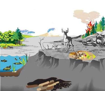
Natural system is a living system, which continuously interacts with its environment or surrounding. This interaction gives energy as well as transfer of material in or out of the system boundry for example:
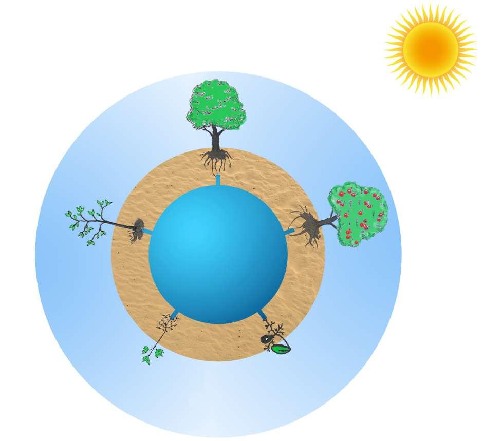
Seeds grow after interacting with its environment or surrounding such as earth (soil, water and sun), then these seeds further develops leaves and become plant ,this plant every summer blossoms and futher in winter fower develop a large fruit after pollination done by honey bees further this plant develop to tree, which every summer blossoms and every winter gives fruit which living beings eat and get energy . And this process goes on. This complex higher level interactive system in nature which is on going cycle which interacts with its environment and surrounding to give energy as well as transfer of material in
6
LIFE CYCLE OF APPLE TREE.
WATER SOIL AIR
SUNLIGHT
Fig A:
or out of the system boundry is a kind of complex as well as higher level sensing in nature.
Such higher level sensing in nature, we can also seen in examples like in Fig B and Fig C.
Photosynthesis
Combusion, and the manufacturing of cement
Carbondioxide in Atmosphere
Carbon released from volcanoes
Fires from use of fuel wood and conversion of forest to agriculture
Aerobic respiration and decay (plants, animals and decompossers).
Aerobic respiration and decay.
Adult
fossil fuels
Egg
Adult emerges
Caterpillar Chrysalis
GROWTH CYCLE OF BUTTERFLY.

7
Introduction
Fig B:
Fig C:
CYCLE OF CARBON DIOXIDE IN ECOLOGY.
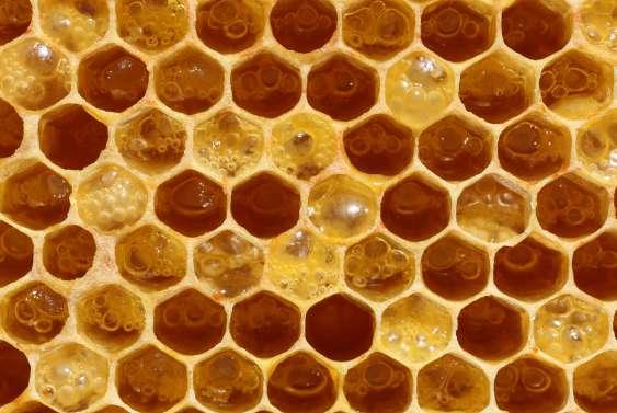
Now with these capabilities of complex interactive system, which are highly based on senses where one is collecting the food and second fnding appropriate space for building like wise the honey comb and also when ants built in communities or honey bees built in communities, each one also inter communicating, that is also a kind of sensing. These kind of complex sensing processes happen within the communities so that they can built . Like we can see in the Fig D, Fig E, Fig F.
In which sensing is one part, perception is one part , communication is one part and building is another part .

The organism, the life makes the ecosystem, the ecosystem makes the ecology and the ecology makes the environment because of such interactive systems. Such organism develops diferently in diferent temperatures.The way the planets orbit the sun and the resulting global distribution of light. The earth has got varying in temperature, equatore is hot and the artic is cold, based on diferent temperature and environment there are diferent species. Natural selection

8
HONEYCOMB MADE BY BEES
HOME OF WOODPECKER ANT HILL BY ANTS.
Fig D:
Fig E: Fig F:
happens through generation. Good adaptors, good services like insects , cockroaches and grasshoppers, egg getting mature, are complex interactive systems in nature.
Some interactive systems in nature are lower level single sensing based, simple interactve systems, such as in Fig G, Fig H, Fig I :
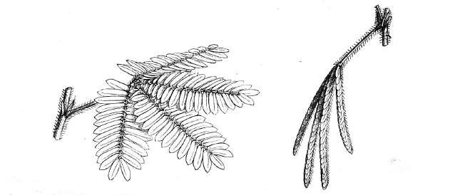
CLOSING AND DROPPING OF LEAVES WHEN MIMOSA PUDICA IS TOUCHED: Where through sense of touch mimosa pudica closes.
CLOSE AND OPEN OF LOTUS FLOWER IN NIGHT AND DAY: Where again through sense of sun light lotus fower open and closes.


9 Introduction
TRAKING OF SUN BY SUN FLOWER: Where through sense of sun light movement happens.
Fig G:
Fig H:
Fig I:
THE OPEN TRAP IS TRIGGERED:
A demselfy lands on the trap and touches the trigger bristles on the trap’s upper surface, bristles here act as sensors. Initially, special cells in the hinge,called “motor” cells, are flled with liquid. As soon as the triggers are fred, this liquid rushed out of the motor cells, making them collapse – motor cells here act as actuator. This causes the trap to spring shut.
CLOSING UP:
After about one-ffth of a second, the slides of the trap are already closing over their victim. Because the marginal teeth point slightly outwards, they help to make sure that the insect does not fall out as the trap shuts – Marginal teeth here act as controllers

To understand more about interactive systems in nature in terms of sensing and adapting the environmental conditions. I have refered a book named ‘Fibre Composite Adaptive system ‘who’s author is Sakthivel Ramaswamy, M.Mingallon and K.Karatzas, they talk about Adaptive system which expains us how interaction takes place in nature.
Some Interactive system in nature for example Thigmo- Morphogenesis refers to changes in shape, structure and material properties that are produced in response to transient changes in environment conditions. We are all familiar with the fact that many plants are capable of movement, sometimes slow as in the petal of fowers which open and close, tracking of the sun by sunfowers, the convolutions of bindweed’s around supporting stems and snaking of roots around obstacles. These movements are sometimes visible to the eye as in the drooping of leaves when mimosa pudica is touched, while some are exceptionally rapid and too fast to be seen as in the closing of the leaves of a venus fy trap.
This interaction between ecology and organism may be known as adaptive system.
Adaptive system: Flexible system that improves its performance (or chances of survival) by monitoring and adjusting its own confguration and operations in response to feedback from its environment.
In all these examples, movement and force are generated by a unique interaction of materials, structures, energy sources and sensors. The material is a cellulose wall of parenchyma cells, non-lignifed and fexible in blending but stif in tension. These structures are the cells themselves and they shape with the aid of biologically active membrane that controls the passage of fuid in and out of the cells. The energy source is the chemical potential diference between the inside and the
10
Marginal teeth Trigger bristle
of leaf - Motor cell
Midrib
Damselfy touches trigger bristles
Lower part of leaf B. TRAP CLOSING A. OPEN TRAP
Damselfy is caught in closing trap Kidney shaped leaf tip
Fig J: VENUS FLY TRAP
outside of the cells and the sensors are yet unknown. These systems are essentially work as networks of interacting mini hydraulic actuators, liquid flled bags, which can become turgid or faccid, owing to their shape and mutual interaction they translate local deformations into global ones and they are also capable of generating very high stresses. Similar mechanisms can be seen in operation when leaves emerge from buds and deploy themselves to catch sunlight. Packing the maximum surface area of materials in the bud and to expand it rapidly and efciently is the result of smart folding geometry of turgor pressure and growth. 1
Adaptive -mechanical design in biology deals with the design output arising from a set of inputs received by the evolving or growing organ or organism. The inputs can be external and internal loads, environment changes, etc., which are superimposed on the genetic information available. The evolutionary time-scale is a long one and what we observe as a response in biological organisms is the result of all these inputs over long periods of time. This complex process of sensing and actuation could be termed as ‘Morpho-Mechanical Computation’. The energy input or stimulus received from the environment is transduced into electric signals by biological sensing devices. The electric signals are further processed for an appropriate responsive behavior.
Two other aspects of ‘Morpho Mechanical Computation’ which occur over much shorter time-scales and which involve individuals as opposed to whole species, are Thigmo-morphogenesis, such as various forms of tropism, the opening and closing of stomata cells in leafs and bone-remodeling. What they show is the intrinsic design fexibility due to fbers and fber architectures. The interaction between hierarchies and the modulations between them combined with growth converges into the specifc solution required for a specifc solution. In order to respond to the changes in circumstances, change in fber orientations, modifcation in structural confguration, material properties and form both in local and global scales are altered. 2
Adaptive systems in nature have incredible stimuli-response coordination. A change in the environment is the stimuli; the reaction of the organism to it is the response. Nature adaptive systems range from simple to complex confgurations of sensing devices, actuators, controller logics and inherent energy generators. The adaptive potential is a resultant of continuous evolutionary processes to the environmental pressures under gone by the organism. Lower level organism such as amoeba, fungi and plants display a simpler process of stimuli response coordination as against higher-level organisms such as animals, which respond to multiple stimuli.
11 Introduction
1. Fibre Composite Adaptive System by Sakthivel Ramaswamy, M.Mingallon, K.Karatzas, pg 31.
2. Fibre Composite Adaptive System by Sakthivel Ramaswamy, M.Mingallon, K.Karatzas, pg 32.
Diagram showing the process of morpho-mechanical computation.
Further in this book I have learnt that there are two type of organisms in nature which interacts with nature one is lower level organism here he talks about;
“The case of lower level organisms such as non-lignifed plants adaptive behavior is entirely dependent on control of turgor pressure inside the cells to achieve structural rigidity. Prestressing the cellulose fbers in the cell walls at the expense of compression in the fuid”.3
In single-celled organisms, adaptive behavior is the resultant of a property of the cell fuid called irritability. In simple organisms, such as algae and fungi, a response in which the organism moves toward or away from the stimulus is called taxis. The adaptive behavior emerges through the defnition of the fber material hierarchies in multiple scales. The energy required for actuation is also generated with in the material system, in case of plants through the process of photosynthesis and distribution of nourishment to alter the osmotic pressure the chemical disintegration in case of single celled organism.
Another is a high-level organism, which perform complex patterns in nature;
“In higher-level organisms”, adaptive behavior involves the synchronization of events which occur in diferent parts of the body, a control mechanism is located between the stimulus and the response. In multi-cellular organisms, this controller consists of two basic mechanisms by which integration is achieved, chemical regulation and nervous regulation. In chemical regulation, hormones are produced by well-defned groups of cells and are either difused or carried by the blood to other areas of the body, where they act on target cells and infuence metabolism or induce synthesis of other substances. In animal, in addition to chemical regulation, there is another integrative system called nervous system. A nervous system can be defned as an organized group of cells, called neurons, specialized for the conduction of an impulse, an excited state from a sensory receptor through a nerve network to an actuator.4
12
ENERGY DEVICE ELECTRICAL SIGNAL FILTERING PROCESSING RESPONSE BEHAVIOUR SENSING CONTROL ENERGY ACTUATION (Stimulus) (transduction)
3. Fibre Composite Adaptive System by Sakthivel Ramaswamy, M.Mingallon, K.Karatzas, pg 33.
+ + +
4. Fibre Composite Adaptive System by Sakthivel Ramaswamy, M.Mingallon, K.Karatzas, pg 34.
Introduction
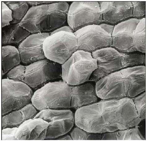
Organisms that possess a nervous system are capable of much more complex behaviors which allows for rapid responses to environmental stimuli. Therefore, higher-level organisms have a complex system for sensing and actuation functions. There is a multifarious integration between sensors, controllers and actuators. To maintain homeostasis, the stimulus generated from the inputs, go through flter processing which leads to decision-making capabilities in higher-level organisms. An equivalent to this in the man-made world is artifcial neural networks, which have multiple inputs processors, which generate multiple outputs based on predefned rules. The energy required for actuation is again generated within the organism by the process of metabolism.” This classifcation is based on the diagraming understood as higher level and lower level.5
Micrograph showing LOWER LEVEL ORGANISM, Parenchyma cells in plants which act as mini hydraulic actuators, by changing the osmotic pressure inside their cell walls.
Micrograph showing HIGHER LEVEL ORGANISMS, Neurons, forming neural networks in the nervous system and a neuron cell group responsive to multiple stimuli.

13
S
E E
S A A
C
5. Fibre Composite Adaptive System by Sakthivel Ramaswamy, M.Mingallon, K.Karatzas, pg 34..
Fig : K
Fig : L
In this book again higher level and lower level organisms are defned through cartesian wax, which is one kind of approach, and hyposurface, an another kind of approach. So there are three approaches which I have infered from this study , like wise how he has classifed now I am understanding these three new examples :
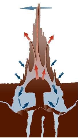
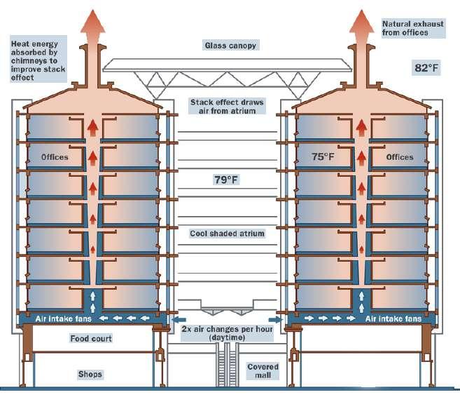
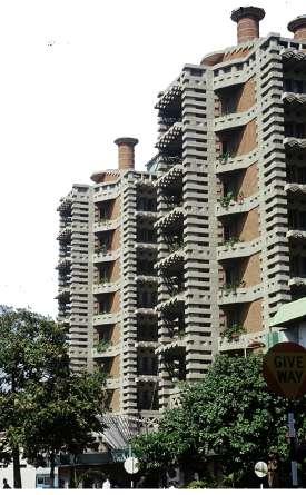
1. Eastgate centre in Harare, zimbabwe where microclimatic control is done through passive control system which was developed by understanding termite mounds. Passive cooling systems are particularly appropriate for this part of Africa because, long before humans thought of it, passive cooling was there in local termites mound. Termite mounds include fues, which vent through the top and sides, and the mound itself is designed to catch the breeze. As the wind blows, hot air from the main chambers below ground is drawn out of the structure, helped by termites opening or blocking tunnels to control air fow. And thus automated air-conditioning system of Macroterms bellicosus termites is one of the fnest constructions in animal kingdom, which is an interactive system in nature.
14
Cool Air In Hot Air Out
Fig O: CONTROLLING OF MICROCLIMATE IN EASTGATE BUILDING inspired from Macroterms bellicosus termites mounds.
Fig N: TERMITE MOUNDS controlling microclimate.
Fig M: EASTGATE CENTER in Harare, Zimbabwe
Spheres
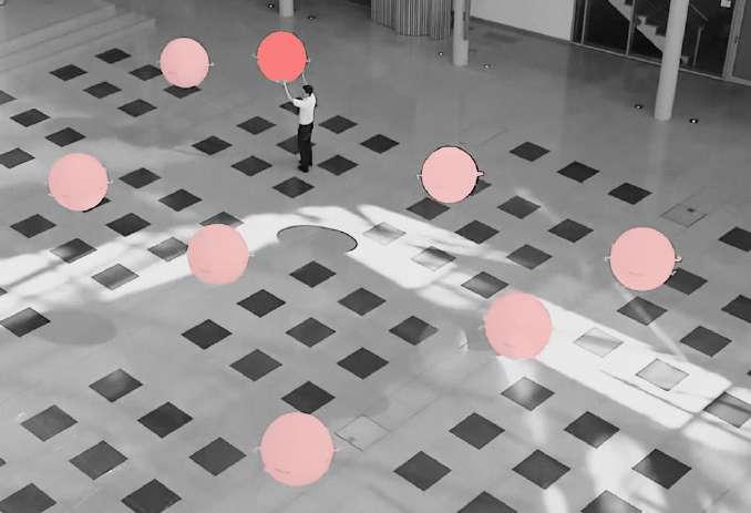
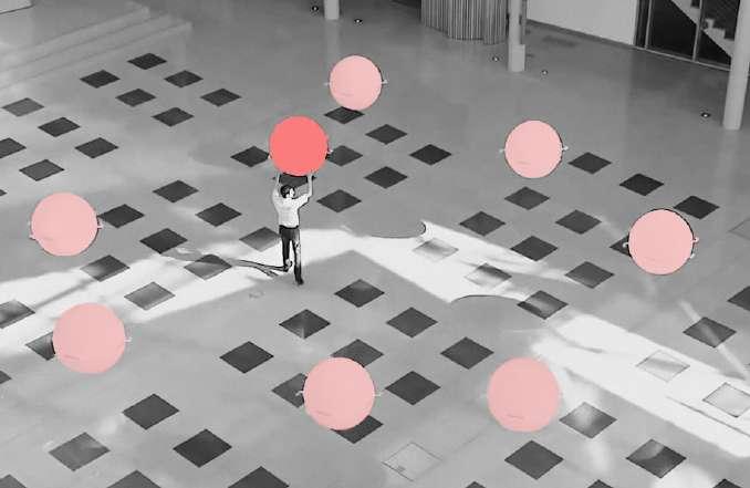
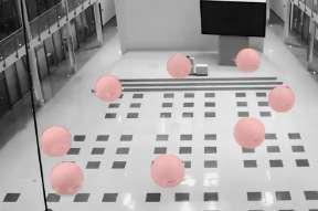
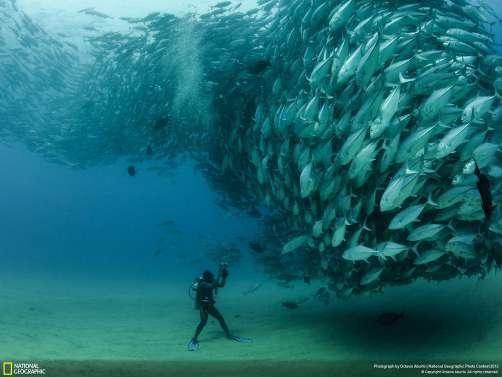
2. Emotion spheres by Festo. Which is user interactive system. Where eight sphere foat together with a complex controlling system including sensors and actuators where they communicate within them and perform complex behavior by staying together but when user such as human comes in contact they rearrange themselves and start communicating with users and interaction takes place, hence now the user becomes part of the system. This kind of complex patters can be seen in nature when fshes moves in a group to protect them selves from predators and form complex patterns, group of birds fy together and form diferent interesting patters by synchronizing each and every action.
15
Introduction
Fig P: EMOTION SPHERES by Festo, Germany
communicating creating the patterns like -‘focking of birds’.
B. Individual Spheres moving to protect them selves from predator .
C. Spheres communicating and rearranging themselves to get protected from predator.
A.
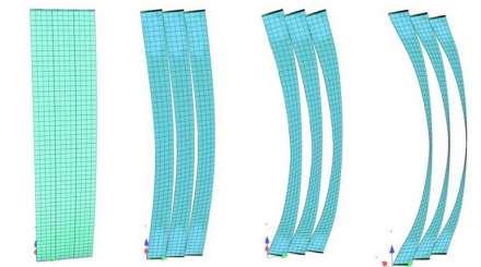
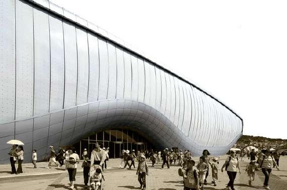
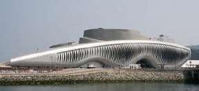
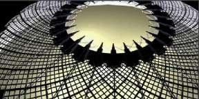
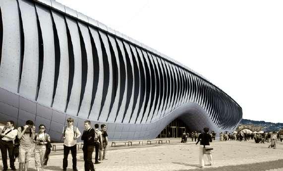
3. Retractable dome by adaptive building initiative. Dome in nature is created by a tiny butter fy larva in order to protect its case with a dome assembled of its own larval hair, echoing the geometry of Buckminster fuller’s geodesic structures, Now adaptive building initiative has developed the dome which opens and closes to control light conditions in interior. And another example to this is SOMA KINETIC FACADE- operation is incorporated in soma ocean, thematic pavilion of expo 2012, Yeosu, Korea where due to light condition facade opens and closes to control internal temperature.
It consists of 108 kinetic lamellas, which are supported at the top and the bottom edge of the facade. The lamellas are made of glass fbre reinforced polymers (FRP), which combine high tensile strength with low bending stifness, allowing for large reversible elastic deformations. The lamellas are moved by actuators on both the upper and lower edge of the FRP blade, which induce compression forces to create the complex elastic deformation. They reduce the distance between the two bearings and in this way induce a bending which results in a side rotation of the lamella. The actuator of the lamellas is a screw spindle driven by a servomotor. A computer controlled bus- system allows the synchronization of the actuators. Each lamella can be addressed individually within a specifc logic of movement to show diferent choreographies and operation modes. Upper and lower motors often work with opposite power requirements (driving – braking). Therefore generated energy can be fed back into the local system to save energy.
16
Fig Q: RETRACTABLE DOME by ABI
Fig R: SOMA KINETIC FACADE - thematic pavilion of expo 2012, Yeosu, Korea
B. Lamellas is closed to control light conditions in the foyer
C. The lamellas actuates to create animated patterns on the facade
A . The longer the single lamella – the wider the angle of opening – the bigger the area afected by light.
Introduction
A brief of understanding from previous examples in nature as well as studies in man made world that how does interaction happen in nature, is as follows:
In all over the world climate is diferent, each organism is diferent, each organism interacts with its environment and there are concepts of camofaging where they sense the environment and morphs themselves to that and there are creatures which goes in water , goes on land, goes in air, when they go in water they have developed fns, when they go on land they have develpoed legs, when they go in air they have developed wings. So it is the same physiological formulae that organism have used to morph themselves into diferent things, which has happened over time. This has happened because of sensing and feedback developing new characteristics over every generation. Like wise how it happens in nature we talked about sensing ,we talked about interaction happens in nature and now there is a lot of attempts to develop smart system and adaptive system in human , man-made systems. Now when we talk about sensing there is lot of diferent kinds of sensors availaible in market.
System which undergoes intelligence of materials like the material properties of lotus leaves as well as mimosa pudica, lotus bud which , senses and adapts its surroundings, shows certain kind of behavior through act of movement ‘actuation’ and controls it as well accordingly like in termite moulds and in the nural signal of humans which gives response to the multiple stimuli etc , such system can be termed as interactive systems.
All around us are living things that sense and react to the environment in sophisticated ways. As structure have become more complex and are being asked to perform ever more difcult missions, there has been an ever increasing need to built “intelligence” into built forms so they can sense and react to their environment . Examples include building that can sense , react to their environment and survive earthquakes as well as change in interior environments with respect to the outer and spacecraft that can sense and repair damage automatically. To perform these functions successfully a ‘nervous system’ is required that performs in a manner analogous to those of living things like sensing the environment, conveying the information to a central processing unit (the brain) and reacting appropriately. Interactive systems are embedded in the live beings and can be understood better, if we study ourselfs, A human system :
17
A human is a living being which has systems like ;
SENSORY SYSTEM- which senses the surrounding and give the localization and environmental model with path planning– internal model and local adaptation, gaits and refexes.
ACTUATORS AND CONTROL SYSTEM – such as the movement of the joints , legs/body and a brain or a nural system which controls and processes the signal given by the sensory system.
ENERGY - which comes from elements of nature like water (liquid), air (wind), light (fre), soil ( Earth), and which get transformed according to the requirement and need.
By understanding such systems i nature man has developed systems which works perfectly with the presence of hardware such as mechanics, actuators, sensors and electronic. Which brings together a system , An Interactive System which adapts , gives response and works intelligently.
Such interactive system in man made world when gets incorporated in building can improve certain dead and unwanted or overdone conditions with in the built environment by interacting with user, can control the light condition in the building, as well as micro climate control inside the buiding and can also result in improving the commercial branding.
Such interactive system can be incorporated after selection of sensors involved with the actuators and defned control system with energy required to operate them. Now we will see that in detail.
“It is not the strongest of the species that survives, nor the most intelligent that survives. It is the one that is the most adaptable to change.” - Charles Darwin
“...By making use of the fexible characteristics of specifc materials combined with motion-based technologies, objects transform in a silent and nearly imperceptible way into a contrasting shape with a completely diferent functionality and expression. As if an extra dimension were involved...”
-Kinetura’s concept 6
18
6. Xaveer Claerhout, interview by Van Poucke, Kinetower+Exclusive interview with Kinetura, Feb 28, 2011, http://blog.Kineticarchitecture. net/2011/02/Kinetura_Kinetower/.

19 User
USER LIGHT MICROCLIMATE BRANDING
CHAPTER - 1 USER
USER
Interior and architecture gives diferent kind of experiences to user but are less dependent on the users behavior, which i have tried to understand in detail previously that “how through activities by giving input to the senses of the user the experience of the user, which is very static spatial experience, can be changed”.
Previously the spatial character of space gives sensorial experiences to the user but if inputs were to be given from sensing the user by using the sensors in the interactive system in space, sudden change in spatial characters will change the static behavior of space to dynamic, responding to user experience.
Now in this case the dynamism in the space will depend on the user unlike earlier where it was independent of user.
Unfurling fern and interactive wall are such studies, which in the presence of user interacts with user and hence change the experience of the user such as spatial experience in the unfurling fern and behavioral experience which depends on the behavior of the user which is further explained in the study of interactive wall.
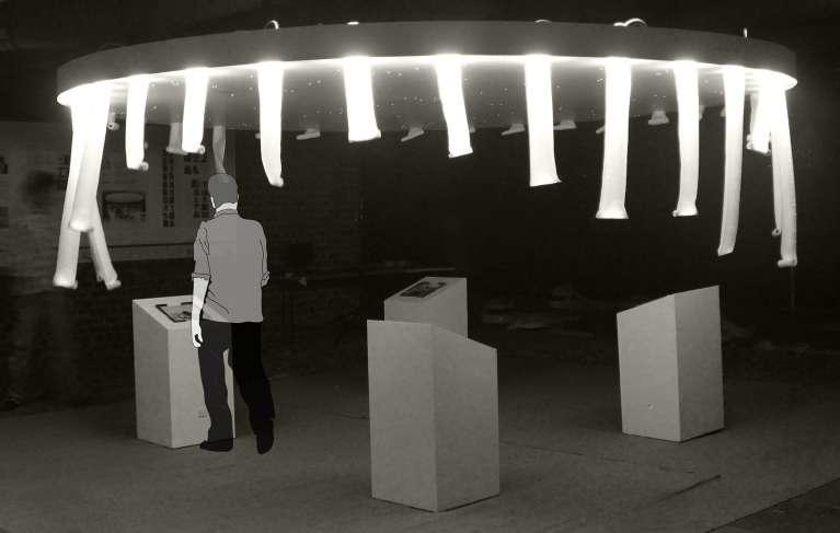
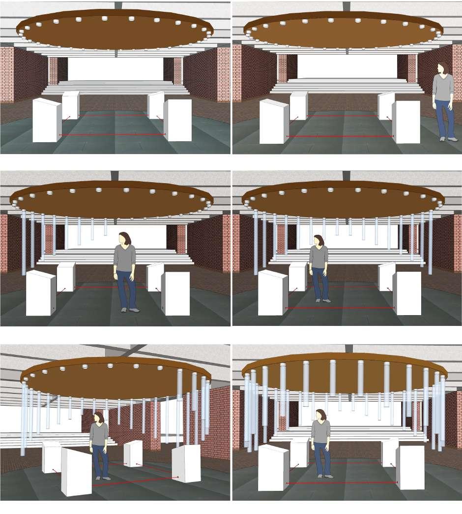
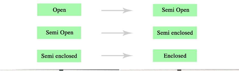
In the Unfurling fern installation, interaction takes place in the presence of the user and hence the spatial experience of user changes in the same space, from - Open to semi open
20
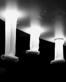
Fig 1.1 : Unferling fern interactive installation.
to semi enclosed to enclosed in a certain time interval and hence this interactive system by the means of dynamism changes focus of the user in the space from open to enclosed and allows him/her to perceive the space in a more focused way.
[Fig 1.1]
When the user was out of the system the space was open and focus was less but in the presence of user the space becomes enclosed and helps user to focus more clearly on the activity for which he/she has come in the space, like in the case of unfurling fern to see the display units, for which the interactive system was created.
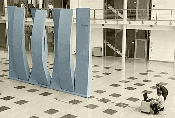
And in the interactive wall installation interaction starts happening as user goes near to the space where the interactive wall is placed. Interactive wall starts interact much in advance before the user notice . The wall start actuation to get the attraction and attention by the users by creating sound. When user comes much closer to see the wall, the wall start behaving, responding to the actions of the user, playing with user. Hence the static wall behaves and interact with user experience space diferently everytime when he enters in the interior of the building.
[Fig 1.2]
Will further understand these case studies deeply that how changes the static space to dynamic by sensing the presence and behaviour of user in the interior spaces.
21 User
Fig 1.2 : Interactive wall installation.
Case Study 1.1 - Unfurling Fern
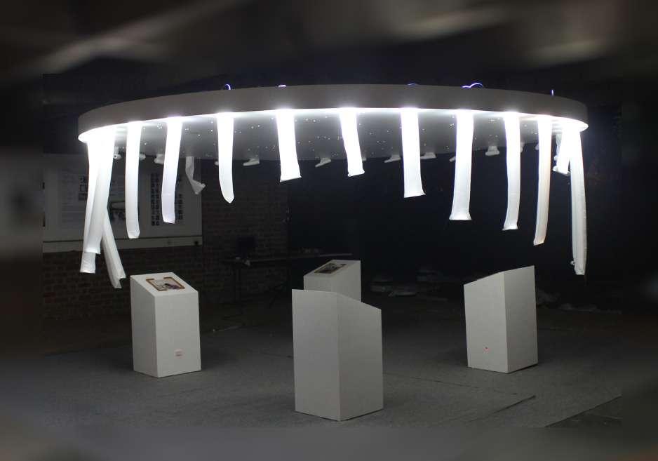
22
Fig 1.1b :Unfurling installation with four display units.
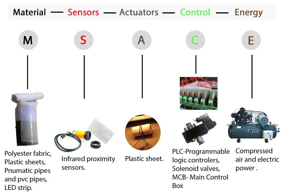
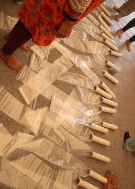
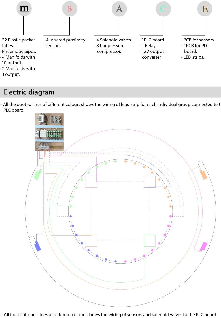
Fig 1.1a: Elements used in interactive system.
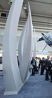
UNFURLING FERN : An open space which transform to semi open to semi encolsed space when senses the presence of user.

Unfurling fern is an installation in the premise of the interior space, which is an interactive system, inspired by a sprouting fern, as the name suggests[Fig1.1c,d]. In this system the simple form of the fern leads to a spatial confguration, which could be interactive and responsive, which is further explained thoroughly. [Fig1.1a,b]
This installation is an outcome of the workshop, held in Faculty of Design CEPT University as apart of the summer school program, a two week workshop on ‘BIONICS’ (Bionics is a feld where boundaries between various sciences disappear. It is at the cross section of Biology, Electronics, Mechanics, Material Sciences, Logics and Computation.), conducted at CEPT by Sakthivel Ramaswamy and assisted by, Rudrapal solanki and Muntaha rushnaiwala and myself Aakash verma.
The domain of the course was Smart and Adaptive Biological systems, which respond to transient changes in the environment. Interaction design, air condition manufacturers (Vardyani Power Ltd, Shilaj) and innovators, had shared their knowledge
The installation generates curiosity through the display units and extends an invitation to the visitor. As visitors move through the installation the embedded sensors translate the data of movement to the logic controllers. The logic controllers are computed to activate the unfurling ferns in sequential modules to create an interesting spatial envelope.
23 User
Fig:1.1c : Unfurling fern
Fig:1.1d: Sprouting fern
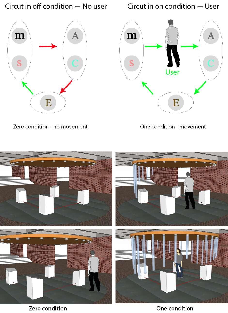
Unfurling fern - Circuit diagram
24
Fig 1.1e : From zero to one condtion.
This interactive system circuit is based on two conditions zero and one[Fig 1.1e,f]. At zero condition there is no movement in the system because of the absence of the user and the system remains static. At one condition when the user comes to see the display unit, the infrared proximity sensors installed in it, sense the user. These sensors give signal to the actuators. Actuators are controlled by logic controllers where actuation happens according to the given logic to the controllers. Logic controller then gives electric signal to the specifc actuators to actuate and thus unfurling of the fern starts, system becomes dynamic. This dynamic system changes the spatial confguration of the space from open to enclose with in a minute, which helps the user to concentrate on the display units. In this system sensor senses as user pass by the installation and makes decisions based on predefned arrays. After the completion of one cycle the interaction with the users still goes on as previously mentioned.
When user has seen the display unit and goes back, these sensors again sense the user and start unfurling showing their presence to the user.
25 User
Zero condition One condition
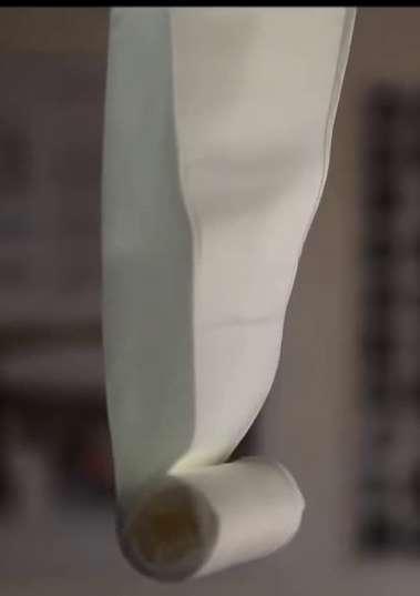
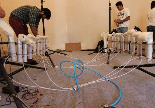
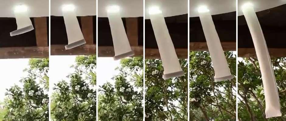
Fig 1.1g : Testing of plastic tubes with pnumatics.
Fig1.1h : Making of plastic tubes.
Fig 1.1f : Fern transformation zero to one condition.
Unfurling fern - Working diagram
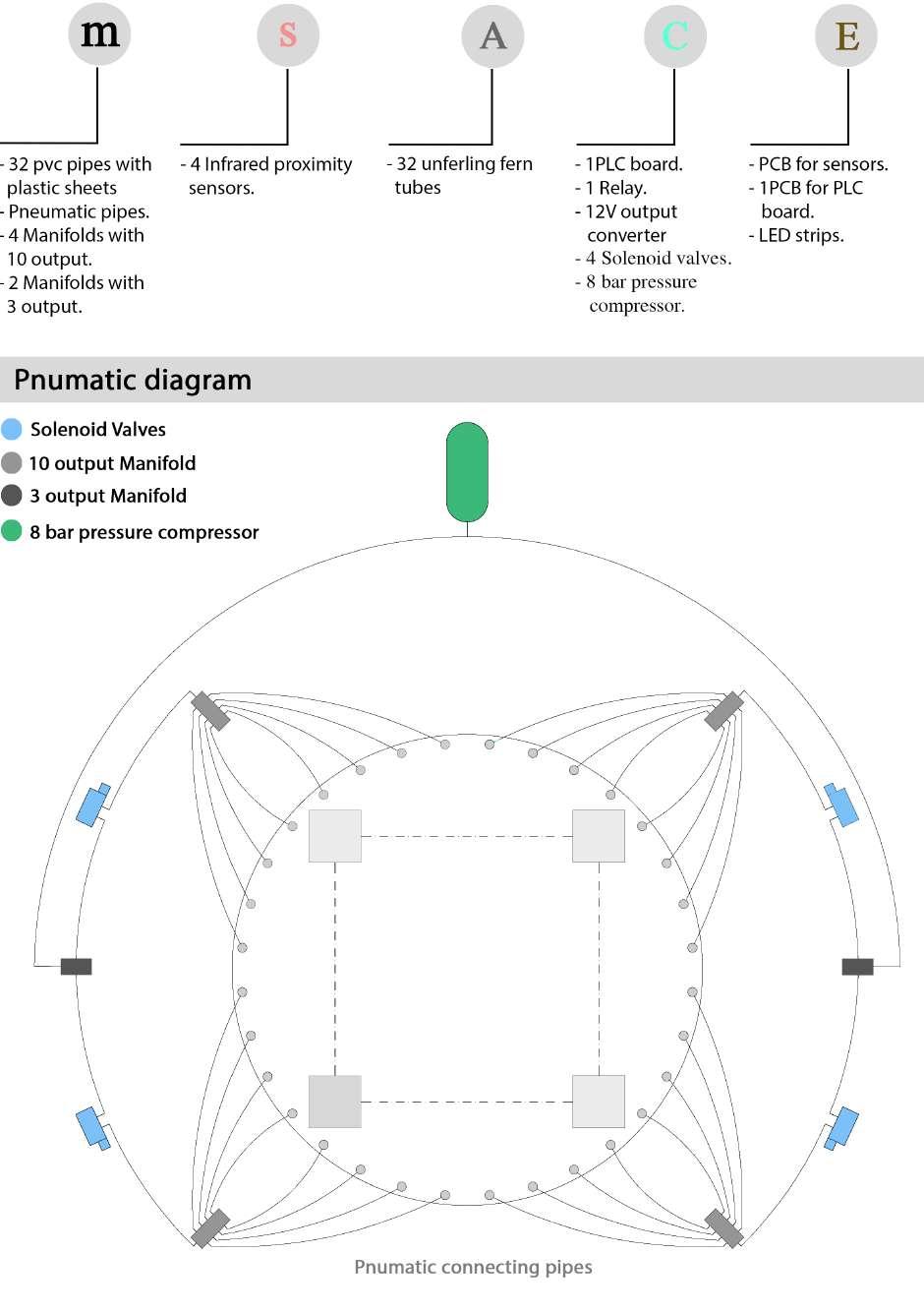
26
Fig 1.1i : Pnumatic diagram of unfurling fern
MATERIAL AND FORM:
The form of The Unfurling Fern was developed from prototyping rather than CAD modelling. The material played a critical role to achieve the coiling efect of the system. The winding paper of motor armatures were used which fnally did the job after a series of material experimentations. The winding paper is coiled up and heat treated to set the shape.
IDEATION:
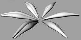
During the Ideation process, we discussed several attributes of the smart systems such as form, geometry, sensors, actuation logic and control parameters. The group was divided into 4 teams to develop several spatially responsive concepts. Some of the ideas were inspired from Mushrooms, Dragon Fly Wings, Trees and so on. Some interesting actuation ideas were on Musical Trees, Adaptive staircases and acoustically transformative structures.
SENSING:
Biological systems have extremely advanced sensors which pick signals at a nano scale and respond in the global scale. Owing to the limited time of the workshop we explored infrared proximity sensors extensively. The reliability of the proximity sensors helped us develop a robust smart system. The sensors are connected to a 24 DC power supply, which on sensing gives an electrical signal of 24 DC as an output. The programmable Logic controller then further processes this output.
ACTUATION:
The aim of the experiment was to develop an Bionic InteractiveSystem which could change shape similar to the diferentiation of Osmotic pressure within the Parenchymatic plant cells. Hence pneumatics-air pressure and fow rate were used to control the shape change within the system.
The advantage of Pneumatics is high mechanical strength derived out of air pressure, but we were focusing on subtle shape changes within the system. The mechanical system deployed here are air packets that perform the actuators function. The actuation in the system is closely related to the form.
CONTROLLERS:
PLC- Programmable Logic Controllers are used in responsive system. The PLC modules are versatile and ofer a wide spectrum of control logics with multiple inputs and outputs. The controllers can function as signal receiver and organize the received data by counting and comparisons. The counter function and analysis function could then be programmed to deliver any desirable output to actuate the components.
LOGIC AND COMPUTATION:
The efcient functioning of any Interactive or adaptive system relies on a lucid logic. The installations ‘The Unfurling Fern’ was developed on logic of human interactions, which is a simple logic. The ferns, which are 32 in all, are divided into modules of 8. As the visitors enter the installation the sensors pick the signal. The sensor’s signal activates one module and consecutively two modules are activated with a time lag and with a further time lag the 4thmodule is activated. During this cycle no further signal from the sensors are processed. The whole system is based on pneumatics, which consists of four solenoid valves, diferent types of manifolds (3,10) and 8 bar pressure compressor connected by pneumatic pipes, as explained in the pneumatic diagram.[Fig 1.1i]
27 User
Unfurling fern - Components
28
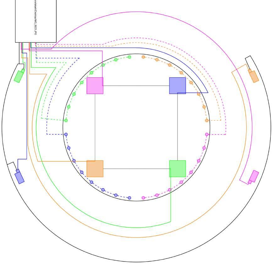
Fig 1.1j: Electric diagram
In the electric diagram of unfurling fern, all the four groups are shown in diferent colors. Each group contains one solenoid valve, eight plastic packets with individual L.E.D strips (unfurling fern), one proximity sensor and one manifold with 10-outputs.[Fig1.6a]
Solenoid valve, Pneumatic plastic packets and manifolds are connected with pneumatic pipes to the compressor so that when actuation starts air doesn’t leak. Manifold with 10-outputs is required so that air pressure equally gets distributed to the eight plastic packets and they blow together with the same pressure. Solenoid valve is an electronic valve which when actuates changes the direction of the air fow. After blocking one hole by dummy in the solenoid valve the air fow can be switched on and of through electric current. Inside each Plastic packet there is an L.E.D strip which glows when sensors senses the user.
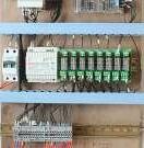
Each group containing one solenoid valve, L.E.D strip and infrared proximity sensors is connected through electric wiring to the PLC board. The PLC board consists of one PLC, one PCB, one relay and 12 volt converter. PLC - programmable logic controller is a device where all the logic is fed through a computer software. MCB - Main control board is a device, which controls the high fuctuation in the electric current and doesn’t allow PLC as well as other electronic device to get efected. Relay device is used to increase the number of outputs from PLC, which give an output of 24V. Converter from 24v to 12v is used for infrared proximity sensors.
To the diagonally opposite of each colored group is the display unit where sensor of the same group is fed. Therefore when the proximity sensor detects the user entering from near that display unit, user will see the unfurling of the fern happening in front of them, these pneumatic plastic packets will guide the user to go through all the display units.
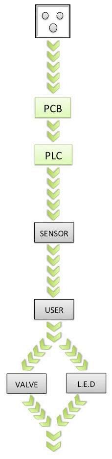
WORKING OF UNFURLING FERN THROUGH ELECTIC DIAGRAM:
When the main wire of PLC is connected to the switchboard, current fows to the MCB. When MCB goes on, the current fows to the PLC. This PLC controls the fow of current to the solenoid valves and L.E.D, but allows the current to fow to all four infrared sensors. Now system is waiting for the user to interact. When sensor senses the user, it gives signal to PLC-Program logic controller and according to the logic, current from PLC fows to the solenoid valve and L.E.D. PLC actuates solenoid valve and L.E.D which results in unfolding of pneumatic plastic packets, thus user’s experience of seeing the display changes [Fig 1.1j,k]. And hence spatial character of space as well as spatial experience of user transforms from static to dynamic.
29 User
Switch board UNFURLING OF FERN PLC Board Electric current
Fig 1.1k: Electric map
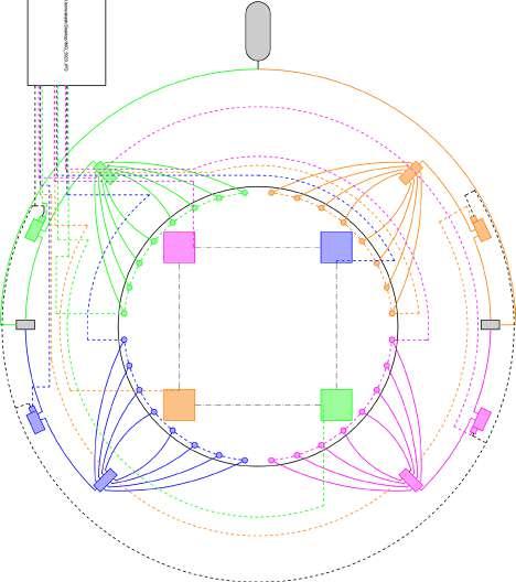
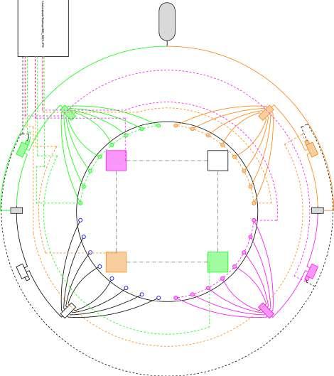
Unfurling fern - Open to enclosed Circuit


30
Fig 1.1l : According to the given logic how with the fow of current in the circuit, changes spatial experience of space from 1. Open to semi open. 2. Semi enclosed to enclosed.
1. Open to semi open- unfurling of green group to orange group.
2. Semi enclosed to enclosed- unfurling of green, orange, pink group to blue group.
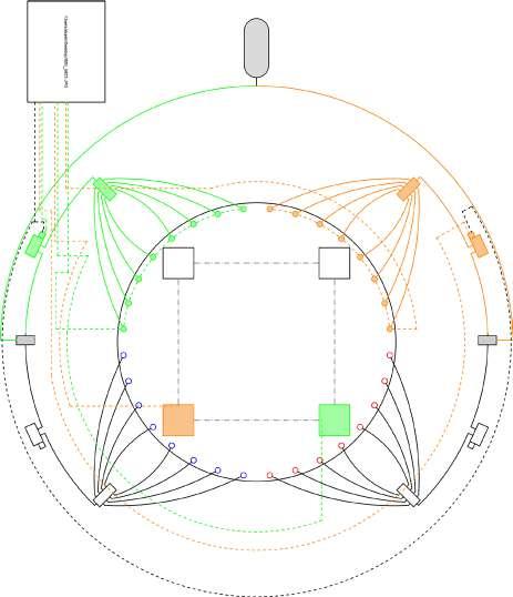
Unfurling fern - Open to Enclosed
31 User
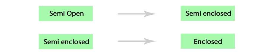
Fig 1.1m : showing the change in spatial experience of space from 1. Open to semi open. 2. Semi open to semi enclosed. 3. Semi enclosed to enclosed.
1. Open - Semi open.
2. Semi open - Semi enclosed.
3. Semi enclosed - Enclosed.
Pneumatic plastic packets, which we named as unfurling fern in an installation, which in groups through sensors-actuatorscontrols and energy, form an interactive and adaptive system. This interactive system changes the spatial experience of user as well as spatial character of space from static to dynamic. This installation was inspired from natures sprouting fern, in this workshop we also created one more similar installation of an interactive blooming fower.
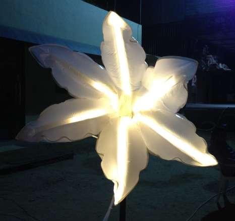
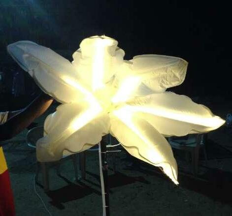
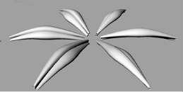
INTERACTIVE BLOOMING FLOWER: Flowers are excellent examples of responsive systems. It is vital for fowers to bloom in response to sunlight. They change their form, orientation and even odour to receive sunlight and attract insects. The moonfower, which blooms at night, was the inspiration of the interactive blooming fower.
The fower was developed with proximity sensors, pneumatic actuators and embedded logic controllers. This experiment set the base for ‘The Unfurling Fern’ refered to us (‘Walk and pop’) and the ‘Tree of Life’ installation (which was called ‘Happy Trees’ amongst our team).
In nature fowers give response with respect to light, here in this interactive system fower blooms and glows with respect to user [Fig1.9 n,o].
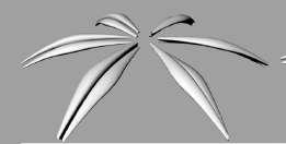
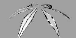
BLOOMING OF FLOWER: Images taken from Cad modeling showing step wise blooming.
32
Image 1
Image 14
Image 28
Image 42
Image 52
Image 62
Image 72 Image 81 Image 90
Fig1.1n : Flower starting blomming
Fig1.1o : Flower continously blomming
THE TREE OF LIFE:

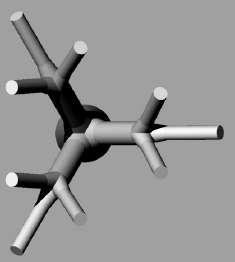
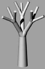
The tree of Life / Happy Tree are a cluster of trees that have ability to intercommunicate, analyze and evaluate the data of visitors and their movement patterns. The form of the tree was developed through parametric modeling on the Rhino-Grasshopper platform from the Fractal/Branching pattern. ‘L’ systems were deployed to deceive the logic, angle and length of branching.[Fig1.1s]
The Tree of Life installation clearly expresses logic, which involves analysis and evaluation of data. Each tree in the installation has a respective sensor. Once the sensor receives a signal the tree is programmed to shake over a period of 5 minutes. The data of the number of visitors visiting the tree is collected. This data from each tree is analyzed with a simple ‘larger than’ function and the tree, which received the minimum number of visitors, is evaluated.
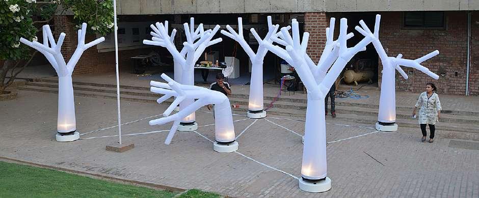
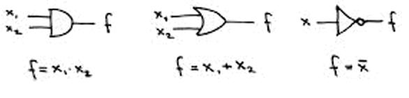
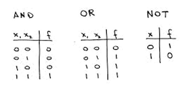
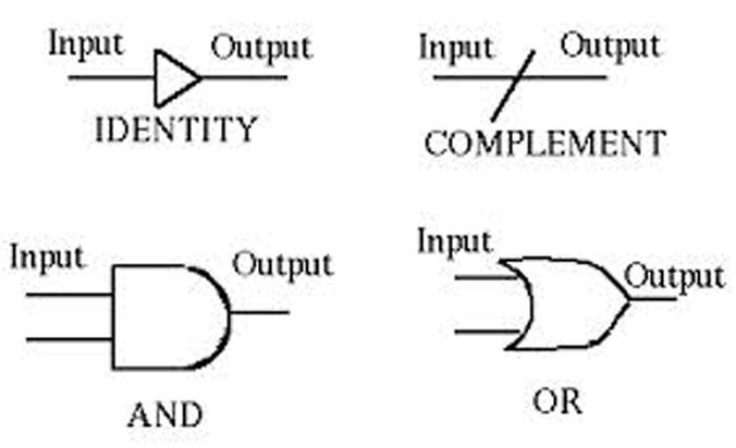
The trees with the minimum number of visitors then droop down and grow back to life. This cycle is repeated every 5 minutes. The computations of the controller are based on the functions such as ‘counters’ and ‘time lag’. The evolution is carried out through the ‘larger than’ function. Finally the pneumatic valves and the blower are actuated with ‘AND’ and ‘OR’ logics.[Fig 1.1p]
33 User
Fig 1.1r : shaking of trees - sensing user
Fig 1.1s : Modelling of tree side elevation,plan.
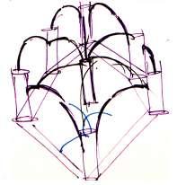
Fig 1.1t : Layout of trees.
Fig 1.1p : Showing AND,OR and NOT gate.
Fig 1.1q : Initial sketch of tree layout.
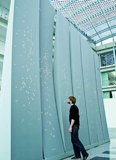
Case Study 1.2 - Interactive Wall
34
Fig 1.2b : Interactive wall - Sensing user and moving
Fig 1.2a: Elements used in interactive system.
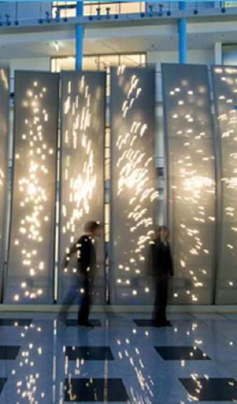
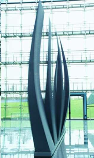
INTERACTIVE WALL: A dynamic wall in interior space gives response by creating sound, displaying patterns of light and movement on its body through sensing the presence and behaviour of user or participant in the interior space.
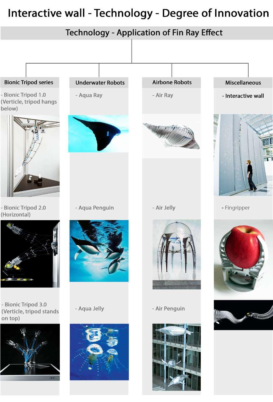
The InteractiveWall is an architectural-scale installation work commissioned by Festo, a leading worldwide supplier of pneumatic and electrical automation technology, for their presentation at the Hannover Messe 2009, the world’s leading showcase for industrial technology. The InteractiveWall was a collaboration between Festo, Burkhardt Leitner constructiv, and Hyperbody, as part of the Festo Bionic Learning Network. The InteractiveWall is composed of seven wall components(called as nodes) based on the Fin Ray Efect, a proprietary technology used in Festo’s factory automation1.[Fig 1.2 d]
Interactive wall demonstrates a new form of architectural as well as interior scale installation that is dynamic and interactive in nature. Interactive wall can either follow a predetermined sequence of movements or interact with people in front of it. It transforms the behavior of trade fair visitors standing in front of it into motion, light and music in real time through sensing, actuation and control, and thus interact with user as well as transforms the experience of space from a static backdrop to a dynamic environment.
An interactive wall is a wall that responds to the user. Interactive Wall consists of seven individual wall elements, each 1.09 meters wide, 0.53 meters deep and 5.30 meters high2. The basic components of each element are a frame structure covered by an elastic fabric skin. Each element consists of motors, sensors, L.E.D, loudspeakers, and interfacing needed to make the element operate. Therefore each element can be considered a self-contained system. These elements comprise a structure with Fin Ray Efect, which was derived from the anatomy of a fsh’s tail fn, which is elaborated in section [Fig 1.2k].
This interactive wall moves about its central axis towards and away from the user, thus showing real time behavior by swinging its body back and forth, displaying patterns of light on its skin, and projecting localized sound by sensing and giving response in the presence of a participant (user).[Fig 1.2 b,c]
1. http://www.hyperbody.nl/research/projects/interactivewall/ -page 2.
2. http://www.festo.com/rep/en_corp/assets/pdf/InteractiveWall_en.pdf
35 User
Fig 1.2d : Interactive wall at the Hannover, 2009
Fig 1.2c : Moving wall displaying patters of light.
Step 3
36
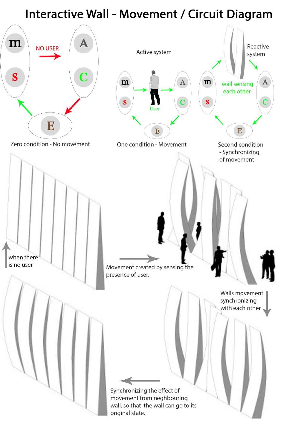
Fig 1.2f : Illustration showing stage wise transformations hapenning in the interactive wall in the presence and absence of user. ‘Digitally-Driven Architecture, Spring 2010, pp. 59’
Fig 1.2e : Showing conditions in the system.
1
Step
2
Step
Step 4
Interactive wall behaves in two conditions; one is when system becomes active where individual Interactive wall segments bend independently in response to the presence of a user and become actuated. Second condition is reactive system where these actuating wall segments synchronize by constantly readjusting its position in order to align itself with the position of its nearest neighboring segments. In this confguration, the individual elements exhibit collective behavior [Fig 2.4]. Further possibility is the continuously variable combination of controlled wave movements and interaction with the visitors. Then in the absence of visitor each segment tends to come back to their original state, which is a zero condition.
As shown in [Fig1.2f]step 1, the 7 Interactive Wall elements in its resting state are aligned in a row. Step 2 illustrates how approaching participants disrupt the Interactive Wall elements, which react to the participants by bending away from them in response to their presence. The bending behavior is a local response, with each element bending independently based on the distance of the participant from the node[Fig 1.2g]. The elements of the Interactive Wall bend independently of neighboring elements in response to the presence of a participant. Although responsively independent, the Interactive Wall elements also synchronize by constantly readjusting their positions in order to align with the position of their nearest neighbors. The synchronised behavior between the elements of the Interactive Wall conficts directly with the asynchronised behavior produced by the response to a participant. The result is a series of complex wave patterns that propagate through the Interactive Wall as a whole; this is illustrated in the phases of step 3. If the wall is left alone it will ultimately come to a resting state as shown in step 4.
37 User
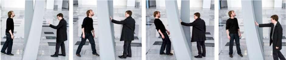
Fig 1.2g : Bending of individual wall after sensing participant and syncronyzing independently when left alone. ‘Copyright Festo AG & Co. KG, photos Walter Fogel’.
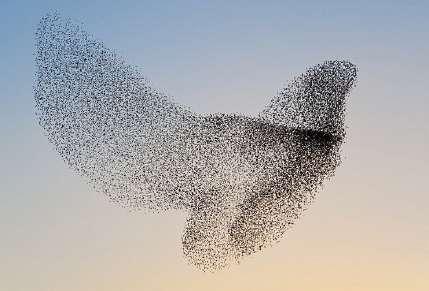
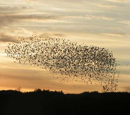
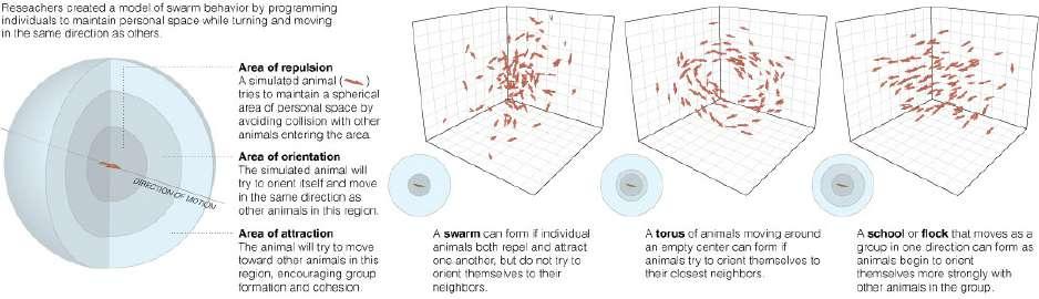
This synchronization behaviour of the InteractiveWall was inspired by the phenomenon of emergent synchrony as described in the book ‘Sync: the Emerging Science of Spontaneous Order’ by Steven Strogatz3 and in his talk on TED, ‘Why things sync up’.4 According to Strogatz, spontaneous synchronous order (which Strogratz describes as sync) is an observable characteristic found throughout nature in systems ranging from physical phenomenon to complex social behaviors. In his talk on TED, Strogatz asserts that the phenomenon of sync is guided by a simple set of four rules:
1. Individual elements are only aware of their nearest neighbors.
2.The elements have a tendency to line-up in relation to each other.
3.While the elements follow each other, they are attracted at a distance (either a spatial distance, a time distance, or both).
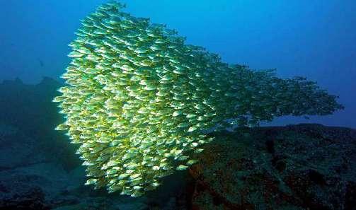
4.Response to stimulus. The agents in a sync system respond as a single entity, rather than as individuals, when their swarm structure is disrupted (for example when attacked by a predator).5
38
Fig 1.2h : Schooling and shoaling of fshes.
Fig 1.2i : Flocking of birds.
3. Steven H. Strogatz, SYNC: The Emerging Science of Spontaneous Order, 1st ed. (New York: Hyperion, 2003).
4.Steven Strogatz, ‘sync’, TED, April 19th, 2010, <http:// www.ted.com/index.php/talks/steven_strogatz_on_ sync. html> [accessed 19 April 2010].
5. Digitally-Driven Architecture, Spring 2010, pp. 58.
Where for the frst three rules he gives examples about how fsh like to stay close together, about a body length apart and Birds try to stay about three or four body lengths apart showing complex patterns in nature[Fig 1.2 h,i]. And when attracted by predator according to the four rules, they move out in random directions, and sense of attraction brings them back together again, so there’s this constant splitting and reforming.
Another way Strogatz illustrates the phenomenon of synchronization in his book is through the behavior of the frefy. Firefies have a tendency to synchronize their fashing tails whenever they are near each other. Through the cumulative efect of their fashing tails, complex patterns emerge out of a simple localized behavior of emergent synchronization. Although they are fairly simple animals, the frefies are incredibly able to maintain this synchronizational behavior even when they are swarming by the thousands.
The behavior of the Interactive Wall can be described in terms of the four rules of synchronization, as described above. While the primary synchronous behavior of the frefy is fashing light, the primary synchronous behavior of the Interactive Wall is movement.Through movement the nodes interactive wall will bend independently of neighboring nodes in response to the presence of a user as we have seen earlier [Fig 1.2f], the InteractiveWall nodes synchronize by constantly readjusting its position in order to align itself with the position of its nearest neighbors.
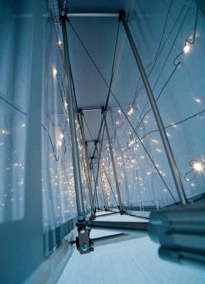
‘Augmented modality of the Interactive Wall’s behavior is light. The skin of each Interactive Wall is covered by a unique, irregular distribution of dynamically controlled LED’s that form a highly reactive interface. The LED skins respond directly to user presence by glowing brighter when users are near, and glowing dimmer as they move away. In addition to dimming, the LED skins pulse rapidly and slowly in relation to node position, having a tendency to fash together when the nodes are in synchrony’.
‘The third modality of the multiple behavior of the InteractiveWall is localized sound, representing only the state of the local sync. Moments of synchronicity are represented by calmer sounds, while asynchronous behavior results more intense sound. The propagation of the sound from high to low intensity is varied throughout the Interactive Wall, thus each node is a member of a choir that sings a complex pattern of oscillating chords’.
39 User
Although similar, the physical movements of InteractiveWall, and the light and sound patterns change independently, reacting at varying rates. The synchronous behavior between the InteractiveWall nodes contrasts with the behavior produced by user presence, resulting in a series of complex wave patterns that propagate through the InteractiveWall structure as a whole’6, which has been inspired from the interaction happenning between frefies in nature.
Hence synchronization in the interactive wall plays the major role in changing the experience of user as well as transforming the light quality in space, thus creating dynamic as well as emotive interaction between user and interactive wall.
A computer model done by Lain Couzin, a researcher in oxford, shows an experiment to understand through mathematical model how in nature swarms form and works. Where do these organizations come from. And how do the rules give rise to patterns? And through this model he has given a better understanding about how in nature frefies synchronize through light in night.
The kinetic behaviour of the InteractiveWall is based on a proprietary technology used in Festo’s factory automation known as the Fin Ray Efect, developed by Leif Kniese of EvoLogics.7
The basic principle structure of Fin Ray Efect was derived from the fns of a fsh. Behavior of fsh fns unexpectedly changes when lateral force is applied, they do not bend but bulge out in the direction of applied force and by this simple principle, fsh deploys the full strength of its fn allowing movement in water. This functional exchange under lateral force provides the basis of many innovative high-tech solutions that utilize the Fin Ray Efect.
6. http://www.bk.tudelft.nl/nl/over-faculteit/afdelingen/architectural-e...ions/works-commissions/interactivewall-prototype-for-an-emotive-wall/ pp. 3
40
Fig 1.2j: Simulating Swarm Intelligence.
7. Fin Ray Efect® is a brand of EvoLogics GmbH, Berlin,Germany.
Each fn ray comprises two fxed struts that are joined at their tips; the struts form an acute triangle. The two pliable fanks are connected by ribs, which hold the fanks apart and allow elastic movement.[Fig 1.2k]
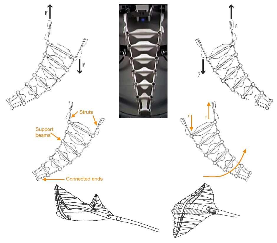
‘The advantage of Fin Ray Efect in Interactive wall is that it can be moved and laterally defected like a mechanical system of levers, by means of just two electric drive units from Festo. This structure moves about its central axis towards and away from the user, thus forming either a convex “hunchback” or a concave “hollow” shape. The Fin Ray Efect was implemented to produce a technically realizable architectonic design by the company Burkhardt Leitner constructive.’8
8. http://www.festo.com/rep/en_corp/assets/pdf/InteractiveWall_en.pdf. pg 2
41 User
Fig 1.2k: Working of fn ray efect and its implementation in fns of menta ray.
42
Interactive Wall - Components
In the Interactive Wall, each element is composed of longer fexible supports (made out of a carbon-composite material) and stif interior supports (made from aluminium tubing). Pushing or pulling near its base will lengthen one side of a Fin Ray element, causing the structure to curve toward the direction force.
ACTUATORS AND CONTROLLERS:
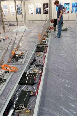
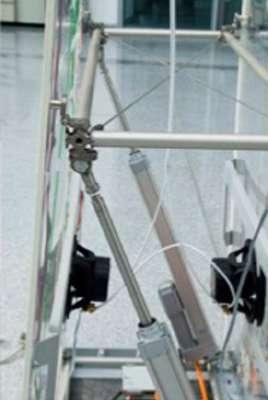
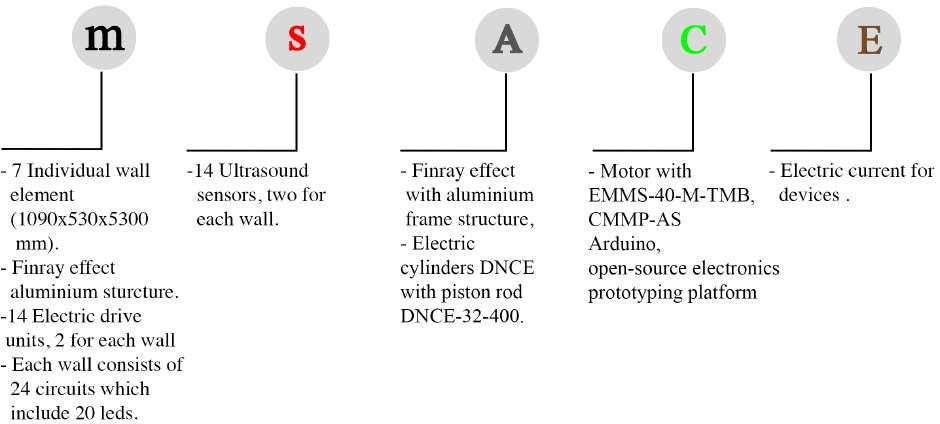
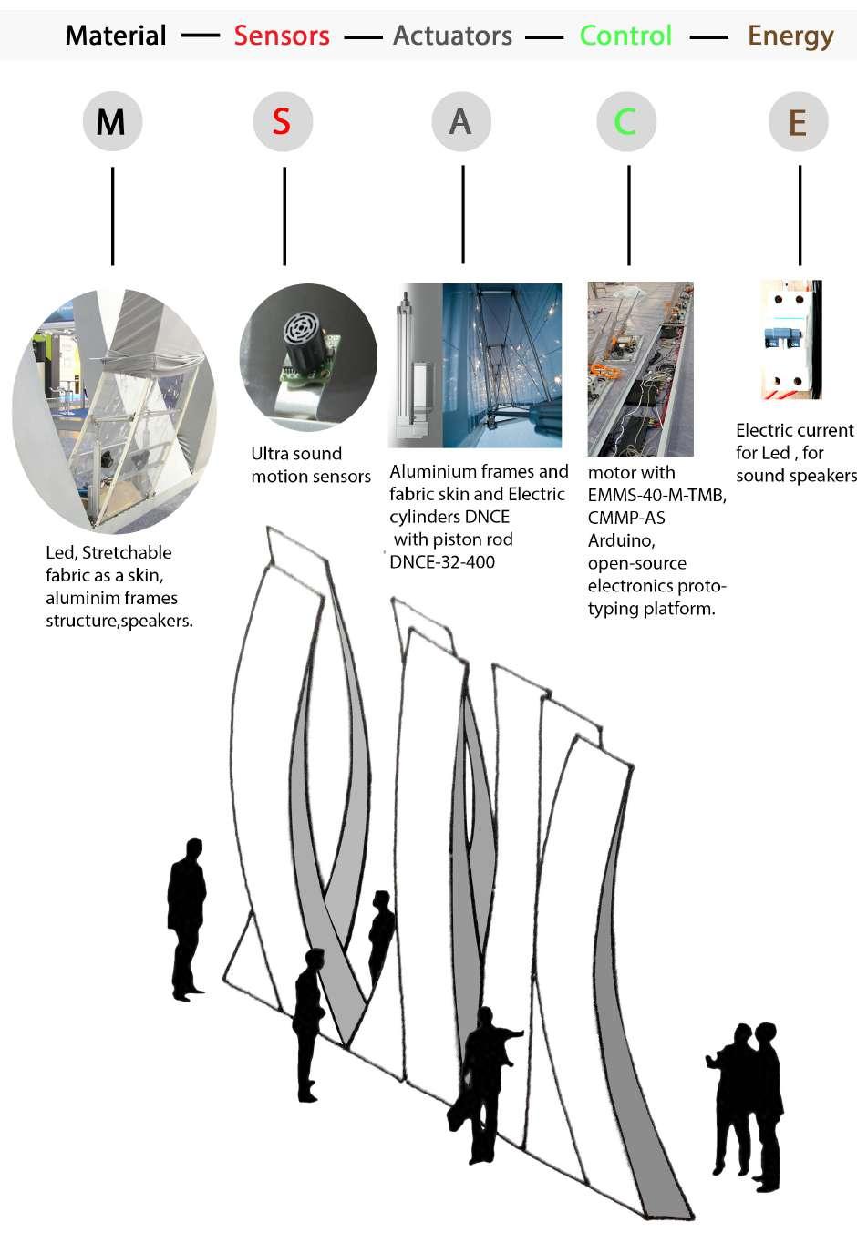
In the InteractiveWall element the shape of a Fin Ray element is controlled using a pair of actutaors DNCE-32400 electronic cylinders, driven by EMMS-40-M-TMB servo motors (provided by Festo AG & Co. KG), which pushes and pulls on one side of the wall element in order to dynamically achieve a desired form. Within each wall element is a Festo CMMP-AS motor controller, which directly controls the position of the servomotors (and thereby the pistons). In order to unify the communications and control, Hyperbody interfaced with the CMMP-AS using custom circuitry built around Arduino, an open-source electronics prototyping platform.9[Fig. 1.2l,m]
In addition to proving an interface to the Festo hardware, the custom circuitry was designed to control lights and read sensor data in each InteractiveWall element. Each element has 48 channels of LED light control. The lights are embedded behind the skin, with 24 channels of LED light distributed non-linearly on each side. The distribution of the 48 light channels was made possible via an LED Painter circuit based on the TLC5940 IC PWM driver, sold of-theshelf by Brilldea.10
9. Digitally-Driven Architecture, Spring 2010, pp. 56, Arduino, an open-source electronics prototyping platform <http://www.arduino.cc> [accessed 19 April2010].
10. Digitally-Driven Architecture, Spring 2010, pp. 56, Brilldea, a developer of interfacing technologies forLED systems, and other prototyping solutions. <http://www.brilldea.com/> [cited April 2010].
43 User
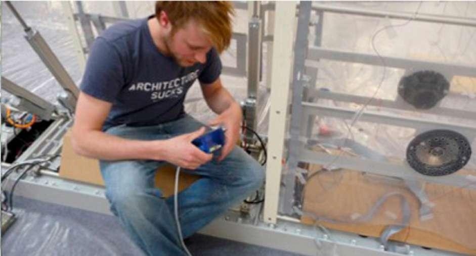
Fig 1.2m : Installating actuators and controllers. ‘Copyright Festo AG & Co. KG, photos Walter Fogel’.
Fig 1.2l: Componenets of interactive wall.
SENSING AND MONITORING:
For sensing, MaxBotix MaxSonar, ultrasound motion sensors capable of detecting distance through sound, were employed. Each InteractiveWall element has two sensors, one for each side. In the software, sensors were combined to create an image of the sensor space, which was used to interpret user presence around the Interactive wall.
Sound production in the Interactive wall was developed using a software package called Ableton Live. Each Interactive wall element has an independent audio channel distributed by a multichannel audio interface, embedded in the base of the composite of Interactive wall elements.
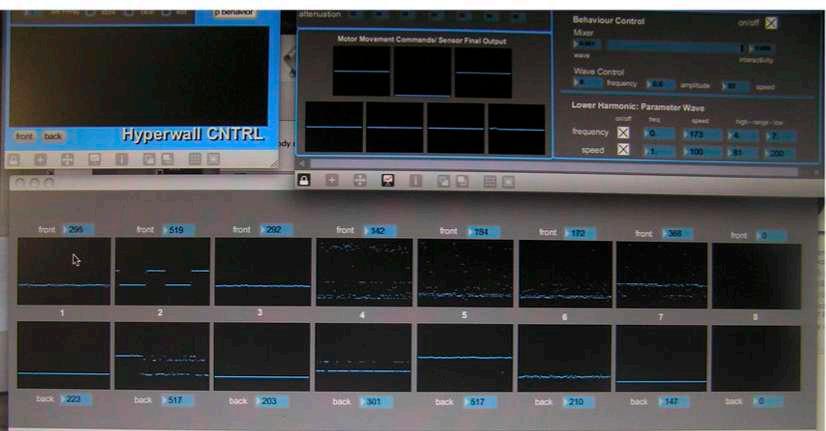
The central point of the various modalities of the Interactive Wall elements was custom-control software, designed in a software development toolkit called Max/MSP/Jitter. Through the interface the various systems of the Interactive Wall could be monitored, sensors could be calibrated and fltered, and the behavior of the system could be controlled [Fig 1.2n].
44
Fig 1.2o : The custom control software for the InteractiveWall, running on a MacBook Pro during the set-up for the exhibition at the Hannover Messe.
Fig 1.2n : The responsive behaviour of the Interactive Wall leads to active participant engagement.
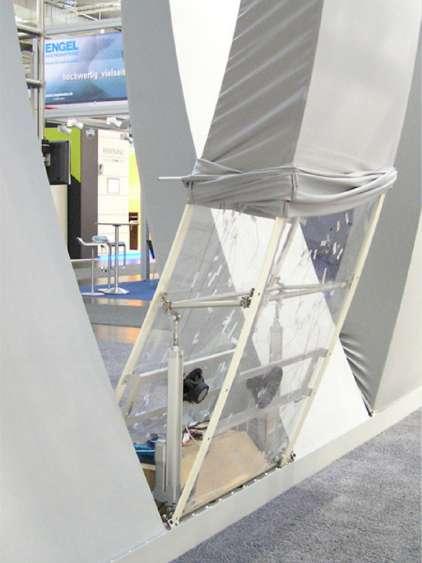
Fig 1.2 n1: Structure inside the one wall component out of seven interactive walls.
11.Digitally-Driven Architecture, Spring 2010, pp. 55-56
LOGIC AND COMPUTAION:

As described previously, users interact with the Interactive Wall by perturbing the synchronous qualities of the Interactive wall. Via the sonar sensors embedded in the wall, both sides of the Interactive Wall are responsive to approaching participants.
[ Fig 1.2p]
Therefore, the Interactive wall often must negotiate between two participants standing on both sides of a component simultaneously. The Interactive wall resolves this situation by favoring the participant who is closest to the wall and responding only to that participant. This gives rise to an emergent game-like quality in the Interactive wall components [Fig1.2n]. The Interactive wall has a tendency to move away from the participant closest to a component. As a result the closest participant is rewarded by the component by being sheltered by the arc of the component’s curved form. Meawhile the participant furthest away from a component becomes even more repelled, because the component is pushing them farther away from the structure.11
45 User
Fig 1.2p : Interactive wall with L.E.D
Fig 1.2q : Making of arduino board.
Fig 1.2r : Attaching all the logic controllers to the installation .
46
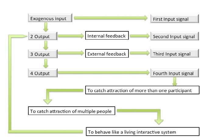
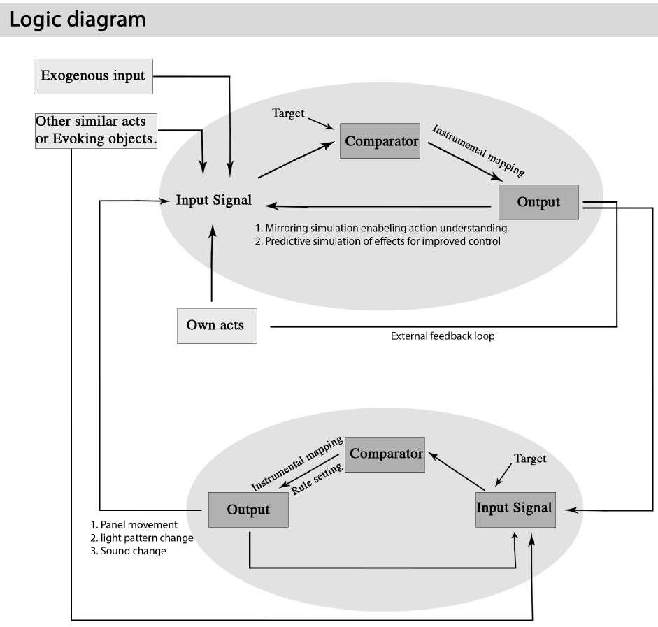
Fig 1.2s : Logic diagram showing Living system of the interactive wall.
Fig 1.2t : Flow chart representing logic.
One participant
One of the designers of the InteractiveWall explained that, when the same participant approaches the same panel for the second time, the panel would react diferently, because the movement pattern of the neighboring panels at that point in time might be diferent than the last time. Internal data communication and its negotiation amongst the seven wall units are thus bound to vary. Apart from this the system also has a memory (case-base) and thus remembers which physical and ambient adaptations have been actuated previously. Just like two persons having conversation on the same topic for the second time, they might speak about things diferently because they remember what had been mentioned and discussed last time. This learning ability and the connected adaptation based negotiations in order to maintain a sustained level of interest within the audience presents a key diference between interactive projects and active projects.12
The interactive walls logic works on multi-loops, a scenario where information is shared in diferent layers within a system through shared circuit model (SCM), which Nimish Biloria, professor at Hyperbody, DELFT UNIVERSITY, Netherland, has explained in a book ‘Rethinking the human in Technology Driven Architecture”.
As he says:
1. In the frst ellipse, there is no specifc target for the participant since in many interactive spaces, when the participants are confronted for the frst time with the space, he or she does not have a clear target of what he or she is going to do with this enviroment.
2. The exogenous input, namely the static or dynamic movement in the space generates input signal 1 to the participant.
3. This input signal goes to the comparator and generates an output. Part of the output goes through the internal loops, in the way of “mirroring, simulation enabling action understanding” or “Predictive simulation of efects for improved control”, to subsequently become input signal 2. The other part of the output goes through the external feedback loop, becoming his or her own action, which is providing a new input, input 3.
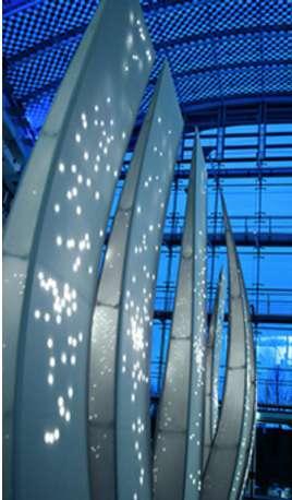
47 User
Fig 1.2u : Stimulation happening in interactive wall
explanation
12. ENHSA - EAAE no 55 Rethinking the Human in Technology Driven Architecture. pg. 130
4. When there is more than one participant, then others’ similar acts (the other participants with similar actions) or evoking objects also become input 4.
5. Looking at the bottom ellipse, meanwhile, the output of the upper ellipse, which goes through the external feedback loop and becomes own action, is giving an input signal 1 of the living system of the Interactive wall.
6. In the bottom circle, there is a target. In the case of Interactive wall, the target is that it wants to attract people, wants to be surrounded by people. So the input signal 1 goes to the comparator, in order to compare if this target has been achieved, and provides this reading as an output.
7. The output also goes through two loops: the internal feedback loop and the external feedback loop. The one that goes through the internal feedback loop becomes a new input signal to the living system, as input signal 2. The output which goes through the external feedback loop, becomes the new input signal(s) to the “self” of the participant, in the form of activation of structural bending of the walls, changing light patterns as well as changing sound.
8. The other participants’ similar acts or evoking objects, are also sending input signals to the living system of the installation.13 [Fig1.2s,t]
Thus this interactive wall based on four input signals, achieves its behavior to the visitors, through physical movements of interactive Wall components, the light patterns and the sound. This behavioral change of this system such as, reacting at varying rates to the participants or attracting the participants, expressing the qualities of its behavior in a unique manner, shows the interaction, which happens in the interactive systems in nature too. [Fig1.2t]
The project interactive wall was initiated by ,Dr. Wilfried Stoll, Chairman of the Supervisory Board, Festo AG .where the project supervision was done by professor Kas Oosterhuis, Chris Kievid, Bernard Sommer, Hyperbody, Faculty of Architecture, Delft University of Technology, The Netherlands Michael Daubner, Andreas Dober, Burkhardt Leitner constructiv, Stuttgart, Germany Markus Fischer, Festo AG & Co. KG. and including project team members Mark-David Hosale, Remko Siemerink, Vera Laszlo, Dieter Vandoren, Hyperbody, Faculty of Architecture, Delft University of Technology, The Netherlands Robert Glanz, Domenico Farina, Burkhardt Leitner constructiv, Stuttgart, Germany Gerhard Bettinger, Roland Grau, Uwe Neuhof, Festo AG & Co. KG.14
13. ENHSA - EAAE no 55 Rethinking the Human in Technology Driven Architecture. pg. 132 14. http://www.festo.com/rep/en_corp/assets/pdf/InteractiveWall_en.pdf. pg 6
48
Interactive wall was created in 2009, before it Hyperbody research group Delft University created three installation, muscle tower I, muscle tower II in 2004 and bamboostics in 2006, which again through sensors, actuators, controllers and logics responds to user as well as changes dynamism in space.
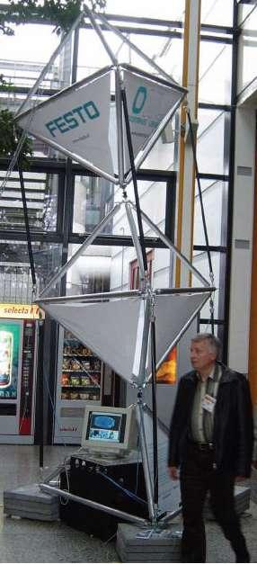
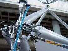
MUSCLE TOWER I AND II (2004):
The Muscle Tower I is a working prototype for adaptive, responsive and pro-active architecture, which responds to stimuli from external, the weather and internal, the users conditions of the built form. The Muscle Tower displays real time behavior [Fig1.2 v,w]. It was displayed at the Aandrijftechniek’ exhibition.
49 User
Fig 1.2v : Muscle tower I.
Fig 1.2w : Muscle tower I- pnumatic actuation.
Pnumatic muscle actuator
Where the possible practical application in the building of this tower could be as follows:
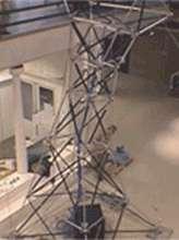
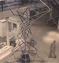
conditions and changed internal usage.
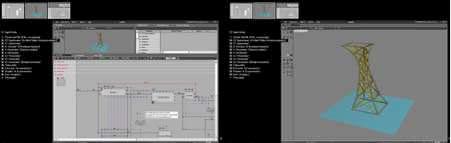
or opens in respons to more or less sunshine.
as to activate changing usage of the space.
making a skyscraper stand perfectly upright when enduring strong winds.15
Where as the muscle tower II is an interactive and kinetic prototype, which reacts to, its environment, and pro- actively determines the space around itself. It consists of aluminium staves, connected fexibly to each other and the Festo Muscles connected by iron hollow spheres. A running program in VirTools controls the Festo Muscles, which is aware of its environment through movement sensors. The Muscle Tower II was an educational and research project developed by Hyperbody. It was designed and built by BSc 6 students within nine weeks. [Fig1.2x]
15. http://www.bk.tudelft.nl/en/about-faculty/departments/architectural-engineering-and-technology/organisation/hyperbody/research/applied-research-projects/muscle-tower-i
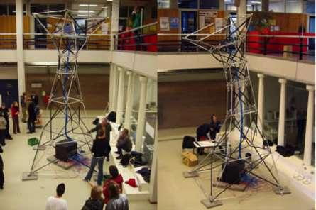
50
Fig1.2x : Muscle tower pnumatic actuation and programming.
A. Muscle tower II at hyperbody.
B. Movement in muscle tower by sensing environment.
C. Muscle tower II modelling in Virtool software.
FACTS:
- Festo muscles controlled through a program called Virtools
- Virtools uses motion and proximity sensors to track the movement of pedestrians.
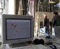
- Virtools then actuates the Festo muscles in response to movement, causing the “trees” to bend toward the sensed movement.
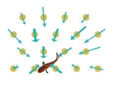
BAMBOOOSTICS(2006):
Bamboostics is an spacious installation such that the visitors can entre. Interaction happens based on the visitor’s behavior. In this installation each bamboostic consists three Festo muscle which is connected to a single pipe which vertically fts in between them, as shown in [Fig1.2y,z]. Festo muscle is controlled by Virtools, which is aware of its environment through movement sensors. Hence tracking of people is done.16
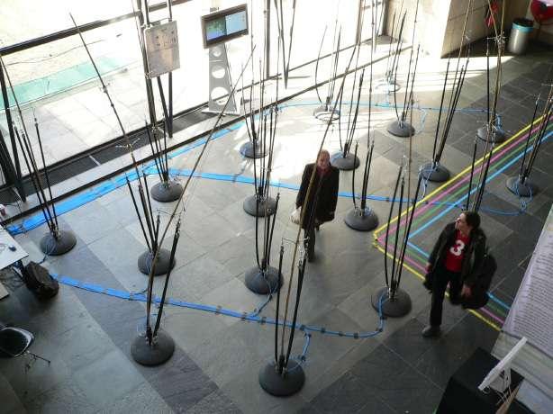
Thus these installations track the motion as well as behavior of user or participants in the space and hence interact with the user. Such technology can create diferent kinds of dynamic spaces, which responds to user as compare to static spaces where user presence does not matter.
16. http://www.bk.tudelft.nl/en/about-faculty/departments/architectural-engineering-and-technology/organisation/hyperbody/research/applied-research-projects/bamboostics
51 User
Fig 1.2z : Bamboosticts installation at hyperbody
Fig 1.2y : Tracking the motion of user through fsh in virtool software.
INFERENCE :
According to these two case studies concept of applying Interactive systems can be categorized into two main categories according to their ability of response to the requirements of their surrounding environment.
interactive systems.
Unfurling fern, blooming fower installations works on simple logic where actuation happens when sensors senses the presence of user and are capable only sensing one user at a time, interacts with user through unfurling and blooming. But remains static in the absence of user. This kind of interaction happening in a system, is a single-loop interaction. Where as in life of tree, actuation happens after sensors sense the user and this data goes for evaluation and hence resultant is based on the programmed logic. This system senses more than one user at a time to perform an activity. It is again single-loop interactive system.
Such single loop interaction in nature happens in interactive systems similar to that plants like sunfower which tracks the sun movement, venus trap which traps the insects when senses touch, mimosa pudica drops down when someone touches it, lotus fower opens in the presence of light, where as moon fower closes in the presence of light.
Single-loop interaction happens in the system, where already particular output is determined for particular input. (Fig 1.4). It is reactive in nature, single- loop system used in a devices which satisfy functional goals, like having building management systems that seek to optimize sunlight distribution or thermostats that regulate internal temperature. Such systems satisfy very particular efciency criteria that are determined during, and limited by the design process.19
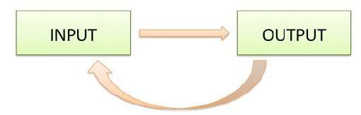
In the feld of Interior Design and Architecture such smart systems would transform the form, Structure, Function and

19.Usman Haque. “Architecture, interaction, systems. ” 2006. P.2
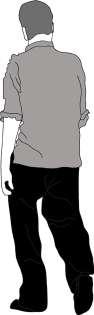
52
Fig 1.4: A diagram of Single- loop interaction where a particular set of inputs determines a set of outcomes.
INPUT OUTPUT USER UNFURN AIR PACKET
Fig 1.3 : Single loop in unfurling fern installation
also Micro-climatic controls of a habitat in the near future. In interactive wall, every time actuation changes according to the change in inputs. This interactive system evaluates multiple logics, which give multiple kinds of inputs, also reacting to every single input at the same time with no disturbance in the system like:
one, which gives more reaction to the action. [Fig 1.5]
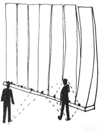
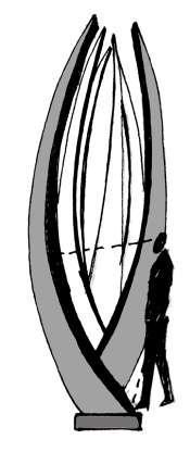
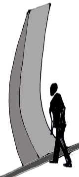
together. [Fig 1.7]
the more participants. [Fig 1.9]
This system, which has four diferent inputs, four diferent logic as well as gives output to all four of them after evaluation. A kind of system where multiple interaction happens is knows as multi-loop interactive system.
Multiple-loop interactive systems; which has higher logics to achieve than the single-loop system, as a certain triggered action provokes its environment or user to interact so the outcome afects frst the trigger itself, giving another outcome to the another cycle as so on causing outputs and inputs in continuous cycles [Fig 1.8]. Multiple-loop interaction does not depend upon complexity where as it depends upon the openness and continuation of cycles of response. It also depends on the ability of the interacting
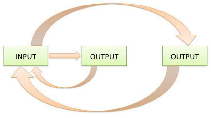
53 User
Fig 1.8 : A diagram of Multiple-loop interactive systems where outputs afect their triggered inputs continuously.
Fig 1.6 : Wall reacting to single participant.
Fig 1.5 : Wall Sensing and reacting to multiple users.
Fig 1.7 : Wall synchronizing with each other.
systems, to have access to, and to modify, each other’s goals. However, for the occupants of a building to have the sensation of a contributing to the organization of a building, the most stimulating and potentially productive situation would be a system in which people build up their spaces through “conversations” with the environment, where the history of interactions builds new possibilities for sharing goals and sharing outcomes. In such architectural systems, inhabitants themselves would be able to determine efciency criteria.20
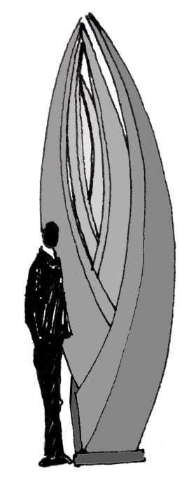
In nature such multi-loop interactive systems can be seen in the intelligence of swarms as previously explained. Like wise honeybees pollinate individually and built honey combs in a group for collection of honey. Such concepts of interactive system from nature will allow more understanding of how and where we can apply this multiple-loop interactive system in a better way such that they improve function as well as energy of a built environment through the act of sensing and monitoring, actuation, control and logic.
Unfurling fern and Interactive wall are such experiments, which can fuse in Interior Design and Architecture with smart, responsive and adaptive interactive spaces. This would lead to an intelligent and responsive spaces which could self organize itself and adapt to multiple efcient confgurations with the changing environmental conditions like temperature, pressure, humidity, human movement.
So far I have discussed how in the presence of user interactive system in space changes static to dynamic, as well as how experience of the user changes according to their interaction and behaviors with the interactive system. Further chapters will discuss how these interactive systems control the light as well as heat in the interior of the building making it more energy efcient. As well as micro and macro climatic control and how interactive systems can control the quality of branding in interiors.
54
20. Dina Soliman Baghdady “The Use of Interactive Applications in the Design of Public Buildings”, 2006,pg 5
Fig 1.9 : Wall Getting attention by user.
55 Light
USER LIGHT MICROCLIMATE BRANDING
CHAPTER - 2 LIGHT
LIGHT:
Interior and architecture enhances as well as changes diferent kinds of experiences and perceptions of the user, being in a static space or in a dynamic interactive system.
When such interactive systems which we has understood previously incorporated in interiors of architecture, due to change in user behavior the space changes, this space gives more emphasized experience to the user in space and also enhances the perception of user in that space.
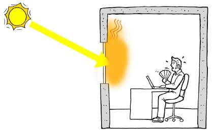
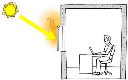
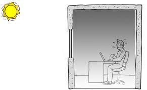
In creating architecture and interiors, light has also played an important role. Light openings as well as light rendering in interior and in architecture for user is always been important. Light is one of nature’s energy. To opt such energy, every built form has element such as windows and louvers, which allows light as well as air into the building, being a part of building facade.
But in interiors light gives a real sense of three –dimensional form and adds character to the space. Translucent and transparency in the materials helps light to travel and extend our vision to perceive the space and its openness. Where as through opaque material where light cannot travel more, we experience the space where we are at present, being a part of only that closed and private space. Hence light plays an important role in the experience, as well as perception of the user.
56
Fig 2.1: User feeling uncomfortable in closed space.
Fig 2.2: User feeling uncomfortable due to excessive heat even in a space which even have opening.
Fig 2.3: User feeling comfortable within a space having opening which controls heat gain.
Sun is a natural source of light. Sun always moves around a built form in a certain path creating shadow in and out of the built environment. Sun direction changes the light quality as well as light rendering in the built form. Sometimes due to extensive light conditions built form gets heated up so much that use of fans and air conditioners as well as shading devices like automatic louvers and curtains in the building facade has been incorporated, so that interior environment of the building is more comfortable to the user.
Thus control of light is necessary to maintain the heating like temperature and light rendering in the building for the eyes as well as the body of the user, so that user can sustain in the built form as well as the building environment.
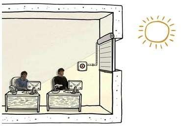
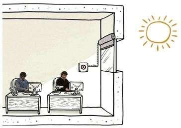
Such systems like automatic louvers as well as curtains are very functional and mundane which do not change much experience as well as perception of the user in the space, as they don’t control the light rendering of interiors and become very static.
In architectural skin as well as in interior screens we need such intelligent and smart systems, which can control the light as well as changes the experience and perception of the user. Such systems, which can sense the light and actuate the screen or facade, which is controlled by the controller, according to the present light condition and improves the light rendering in the interiors can be named as light interactive system.
57 Light
Fig 2.4: Excessive sun light making uncomfortable working environment.
Fig 2.5: Electronic blind unfolds making comfortable working environment when user switch on the electric button.
These light interactive systems can perform action in the interior screens as well as on the exterior shades of the building. Such intelligent facade system experiments are done by A.B.I – Adaptive Building Initiative which was founded in 2008, is a joint venture between Buro Happold and Hoberman Associates dedicated to designing a new generation of adaptive buildings.
According to the A.B.I ‘Adaptive buildings optimize their confguration in real time by responding to environmental changes. While adaptive strategies can be efectively applied to a wide range of building systems, ABI is initially focused on adaptive facades and building envelops. By controlling light levels, solar gain, and thermal performance, our adaptive systems reduce energy usage, enhance comfort.’1
Adaptation is essential to managing the problem of climate change.
A.B.I has created such systems of intelligent surfaces, which responds to the environmental changes happening outside of the building and interacts with the user changing interior spatial quality of space as well as experience of the user. Such intelligent surfaces are:
ADAPTIVE FRITTING AND TESSELLATE – Panels at interior of the building facade, which are continually evolving surfaces, patterns and opacity. [Fig 2.6,7]
STRATA - A building surfaces from nearly nothing. [Fig 2.8]
PERMEA – A dynamically permeable surfacing on building facade. [Fig 2.9]

We will further individually understand the working of such intelligent surfaces individually in detail in the building.
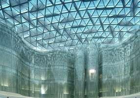

1. http://www.adaptivebuildings.com/systems.html.
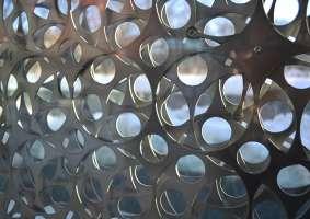
58
Fig 2.6: Adaptive Fritting
Fig 2.7: Tessellate
Fig 2.8: Strata
Fig 2.9: Permea
Such intelligent surface systems works on sensing, actuation, control and energy which after sensing light condition and thermal heat and light rendering gives signal to controllers and does the actuation to control the light rendering as well as thermal heat in the building which suits to the user.
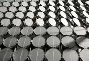
There is another adaptive interactive system known as homeostatic facade system [Fig 2.10] and bimetallic facade system [Fig 2.11] which has been inspired from the concept of human homeostasis and where as bimetal facade talks about how when two diferent metal combine together to form a bimetallic strip which convert a temperature change into mechanical displacement. The strip consists of two strips of diferent metals, which expand at diferent rates as they are heated, usually steel and copper, or in some cases steel and brass. Due to such displacement the facade open and closes controlling thermal heat of the building. In these two system sensing, actuation, control and energy is developed with in a material properties. And through simple mechanisms light quality as well as thermal heat is control in the building environment, which appeals to the user comfort. We will further see how these simple mechanisms in a facade system work.
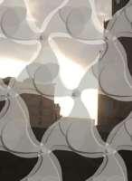
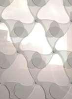
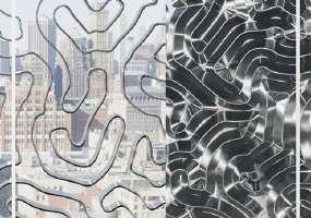
At the last of this chapter we will see in detail two examples of buildings such as Albahar twin towers in Dubai [Fig 2.12] and Design Hub of R.M.I.T building in Melbourne [Fig 2.13], which will talk about, when incorporating such system in the building systems how building can become more energy efcient.
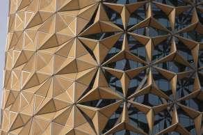
59 Light
Fig 2.12: Albahar tower
Fig 2.13: R.M.I.T building
Fig 2.10: Homeostasis facade
Fig 2.11: Bimetallic facade
Case Study 2.1: Intelligent surfaces - Adaptive Fritting
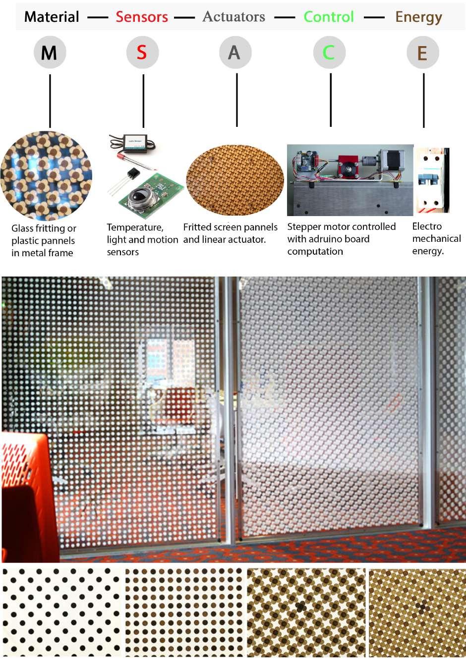
60
Fig 2.1b: Stages of adaptive fritting becoming translucent to opaque surface in an interior.
Fig 2.1a: Elements used in interactive adaptive fritting.
ADAPTIVE FRITTING: A future technology to control light by sensitive building facades as well as interior partitions.
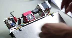
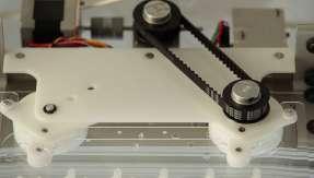
Adaptive Fritting is Chuck Hobermans design. Adaptive fritting uses fritted glass surface, which controls transparency. Adaptive Fritting can control its transparency and modulate between opaque and transparent states through controlling heat gain and adjustment of light.1
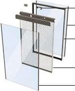
While traditionally fritting relies on fxed patterns, adaptive fritting can adapt the nearby environment and can control the excessive light as well as heat within the interior of the building. This performance is achieved by shifting a series of fritted glass or acrylic layers so that the graphic pattern alternately aligns and diverges.2
Glass fritting is an established treatment for light control and passive solar control in partition walls of interior as well as on architectural facades. Adaptive fritting infuses this treatment with the expanded functionality of movement. When these fritted patterns align the adaptive screen becomes transparent and when patterns diverges the screen becomes opaque. Thus the privacy can be controlled in the space through open - transparent to close – opaque.[Fig 2.1b] This movement in adaptive fritting is done on the same system of sensors, actuators, controllers and logic, which we have learnt earlier. In adaptive fritting this system shows movement when sensors senses the heat and light condition, real time dynamic motion is controlled through motors. These motors actuate the fritted screens. Motion in
1. http://www.adaptivebuildings.com/adaptive-fritting-surface.html.
2. http://www.adaptivebuildings.com/adaptive-fritting-surface.html.
Tempered Glass
Steel Frame
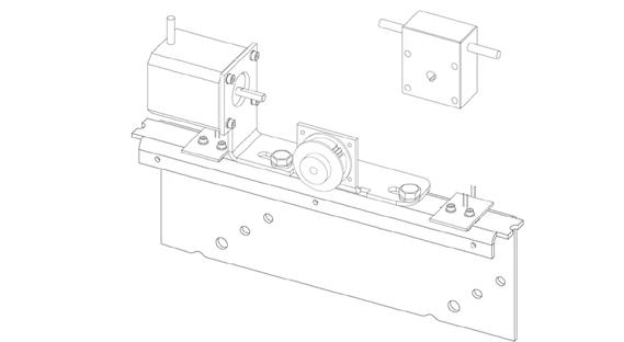
Adaptive Fritting
Tempered Glass

61 Light
Stepper motor linear actuator
Fig 2.1c : Images showing assembly of control and actuator
Fig 2.1d : Image showing assembly of stepper motor linear actuator
Fig 2.1e :Exploded view of Layering in adaptive fritting module.
motors is controlled through the logic controllers.
SENSORS, ACTUATORS, CONTOL AND LOGIC :
In Adaptive fritting thermal and light sensors are used which detect the current temperature and light condition. Stepper motors are used which through linear actuation actuate the fritting [Fig 2.1a]. And the motion of the motors is controlled by given logic.
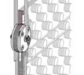
Actuator actuates the Fritted screens. Each component of adaptive screen consists of fve acrylic or glass fritted screens. Out of fve screens top fritted screen is fxed but rest of the four screens actuates through motor.3 [Fig 2.1f]
In adaptive fritting logic works on simple single loop system, which has three kinds of logic. According to the functionality of the space. Such as:
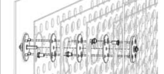
Fig
a. Fritted patterns on the screen overlap each other resulting in transparency.
a1. Fritting pattern diverging from a point of overlapping becoming an opaque surface as shown in image. The diferent colored circles show diferent fritted screens.
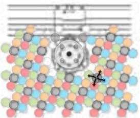
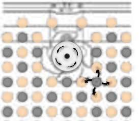
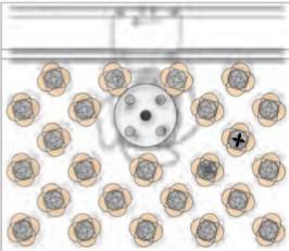
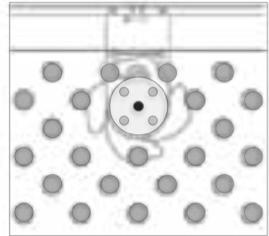
b. Fritted patterns on the screen is half diverged. The point of overlapping is the pattern in the fxed screen.
b1. Fritted pattern diverged from a point with the reduction in the transparency.
62
a a1 b1 b
Fig 2.1f : Image at the left shows the stacked fve fritted screen to the actuator and at the right is the exploded view showing stacking of fve fritted screens with the actuator.
2.1g :
3.
http://www.adaptivebuildings.com/adaptive-fritting-surface.html.
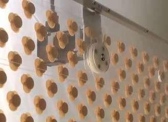
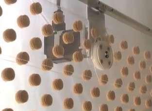
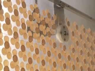
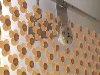
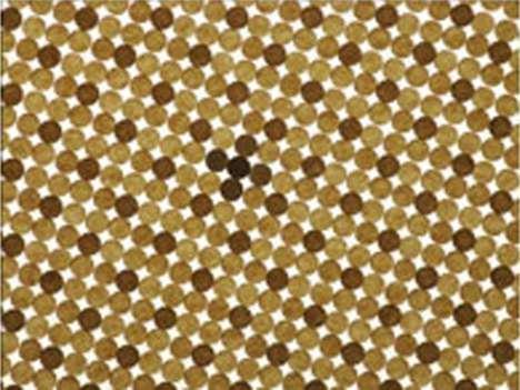
63 Light
Fig 2.1g (a): Images left to right showing how ft patterns in a screen changes visibility from transparent surface to opaque when actuated.
1. When the interior temperature raises more than the give temperature data. Temperature data depends on human comfort. Due to rise in temperature motor create movement in the fritted screen thus fritted patterns on the screen diverges. Becoming transparent to opaque. And when interior temperature goes back to normal, again through sensing, motor actuates the screen and fritted pattern aligns becoming opaque to transparent [Fig 2.1g].
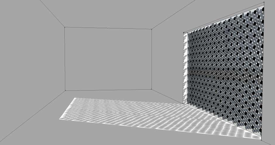
2.When direct ray of sunlight falls in the space than this fritted screen again diverges and improves condition of light in interior. And when light condition is suitable for the user fritting overlaps, becoming transparent. Such screens can be used in south and east of the building facades to control the
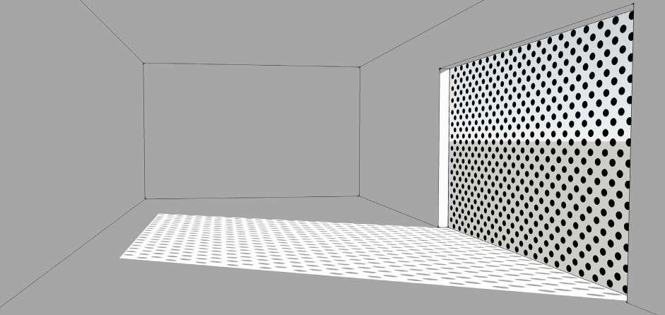
64
Fig 2.1h :Light condition in interior when fritted patterns are overlapped.
Fig 2.1i : Fritted patterns diverges resulting in opaque surface controlling light condition in interior
light condition in the interior of the building [Fig 2.1h,i].
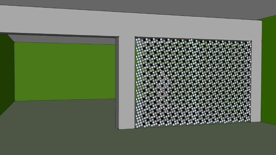
3. When this adaptive screen plays role of a partition element in the interior spaces, which need both privacy as well as visual connection like conference room. The sensors sense the absence of artifcial light and human while there is no meeting and hence the fritting’s overlap each other bringing transparency in the space from both in and outside. But while an on going meeting the sensors sense the artifcial source of light and the movement of the user hence the fritting’s diverges and create an opaque surface, which detaches the viewer of outside from inside. [Fig 2.1j,k]
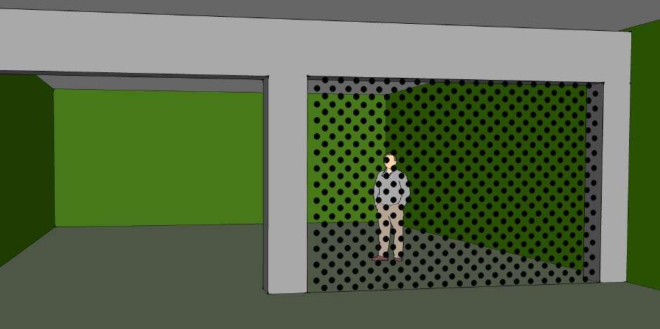
65 Light
Fig 2.1j : Fritted patterns overlaps providing transparency.
Fig 2.1k : Fritted patterns diverges becoming opaque and hence detaching the viewer of outside from inside.
Adaptive screens has been incorporated in the building to achieve such functionality in spaces such as:
1. An installation created, a curved wall at Gund hall in Harvard University Graduate School of Design. (2009)
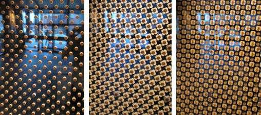
2. An installation created in two parts, the main sliding glass doorway and an adjacent moving glass partition wall for the entrance of new Wyss Institute for Biologically Inspired Engineering at Harvard University in Boston. (2010)
3. An installation created, a glass conference room wall with adjustable opacity for the AHHAA Science Centre in Estonia. (2011)
Curved window(2009): Based on adaptive fritting a dynamic installation was created at Harvard Graduate School of design. The technology utilizes a graphic pattern in order to control heat gain and modulate light, while allowing sufcient transparency for viewing.4
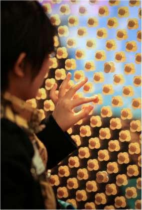
The installation at Gund hall consists of six motorized panels ftted in a window of 1.2mx 7.2m, incorporated in a curved wall. These panels are programmed to form a dynamic feld where light transmission, view and enclosure continuously adapt and change. As the panel transform, the visual efect is of sparse dots blossoming into an opaque surface. This opaque surface is achieved by shifting a series of fritted glass layers, which aligns and diverges the graphic pattern.5
[Fig 2.1l]
This installation was commissioned for a joint exhibition and conference titled Ecological Urbanism : Alternative and Sustainable cities of future.6
4. http://www.adaptivebuildings.com/adaptive-fritting.html
5. http://www.adaptivebuildings.com/adaptive-fritting.html
6. http://www.adaptivebuildings.com/adaptive-fritting.html
66
Fig 2.1l : Transition of fritted screens from transparent to opaque.
Fig 2.1l(a): Human interacting with adaptive screen.
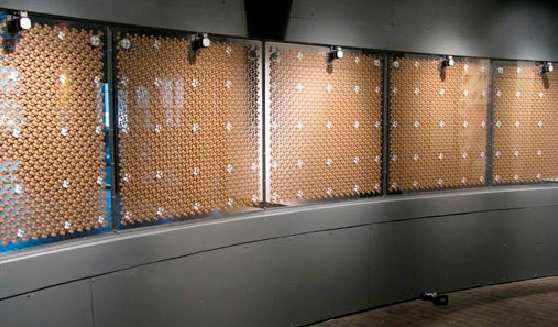
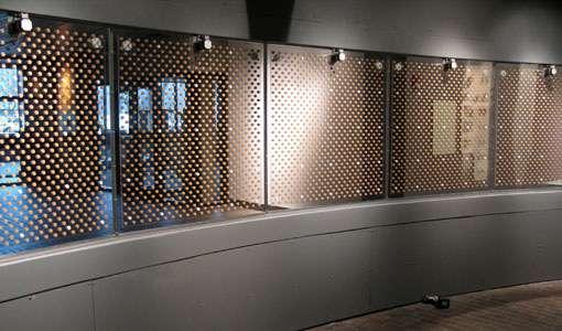
67 Light
Fig 2.1m : Fritted patterns in a curved window are overlapped on each other providing transparency by sensing the absence of light and user in the space.
Fig 2.1n : Fritted patterns in the curved window are diverged becoming opaque by sensing the presence of light and user in the space and hence restricting the visual connection.
Door and partition wall (2010): Adaptive fritting has been incorporated in an installation for the main entrance at the Harvard University in the Wyss institute of biologically inspired engineering.
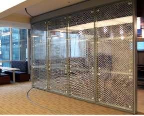
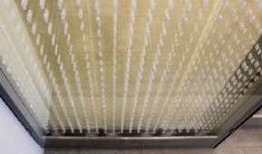
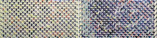
An installation is in two parts one part encompasses the main sliding glass doorway and the other is an moving glass partition wall, adjacent to the doorway. The sliding door is made up with the graded pattern of hexagonal dots from foor to ceiling that continually shifts in transparency. The sliding door as well as panels are controlled through computer, when visitor approach to the institute, sensors senses the visitor which results in the movement of the panels, fritted patterns overlaps to provide transparency and hence when visitor approaches to the door another sensor senses the presence of visitor and the door slides.7
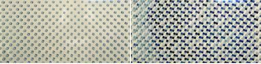
When visitor steps through the doorway [Fig 2.1q]. He notices a full color partition wall, which shows the merging of three-dimensional design with two-dimensional artwork. a twelve custom adaptive fritted units continually shifts its color, transparency and imagery, at instants aligning into one of two alternate images. The fritting artwork in this installation is based on photographs from nature and architecture. These images were abstracted and custom color palette was made which complements the institute’s interior design and architecture.8 [Fig 2.1o]
Both the installations were developed through Hobermans venture A.B.I and its network of partners.
7. http://www.adaptivebuildings.com/wyss-institute.html.
8. http://www.adaptivebuildings.com/wyss-institute.html.
68
Fig 2.1o : Transition from transparent to opaque in adaptive fritted screen, as well as complimenting the interior colour scheme from single to multicoloured fritted patterns making the surface aesthetically more appealing.
Fig 2.1o(a): Sliding door
Fig 2.1o(b): Partition wall
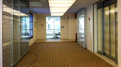
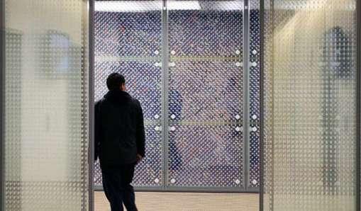
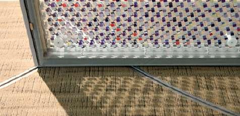
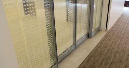
69 Light
Fig 2.1p : Interior view showing movable wall with square multicoloured fritting at the left and sliding door with hexangon white fritting at the right.
Fig 2.1q : Interior view showing fritted sliding door and a multicoloured wall resulting into opaque sufaces by sensing user.
Fig 2.1r : Channels in the foor for guiding the movement of the adaptive fritted wall.
Fig 2.1s : In the absence of user fritted patterns overlap to provide transparency.
Glass wall (2011): A.B.I created a dynamic installation for the AHHAA Science center in Estonia.

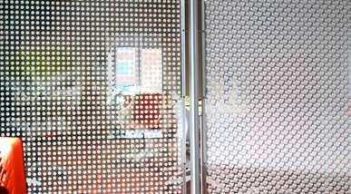
A glass conference room wall was created with fritting which adjusts the opacity. A glass conference contains three panels of living glass- fritting technology. The single glass wall from foor to ceiling measures 1.2m x 2.4m high .Where the opacity is mechanically modulated by shifting multiple layers of clear acrylic with in a graphic frit pattern.9 [Fig 2.1w]
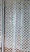
This installation is both functional and artistic creating an intelligent and inviting display of technology for museum visitors. It infuses the conference room occupants with ability to control their level of privacy. Alternatively, the wall is also set to run by creating an art piece that simultaneously demonstrates a new technology and provides opportunities to incorporate topics such as adaptive, intelligent and kinetic surfaces into interiors as well as architecture.10 [Fig2.1t,x]
9. http://www.adaptivebuildings.com/adaptive-fritting-estonia.html
10. http://www.adaptivebuildings.com/adaptive-fritting-estonia.html
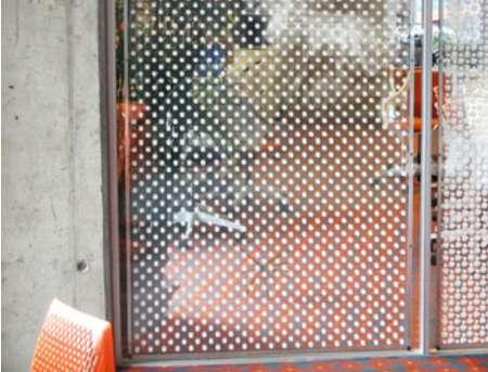
70
Fig 2.1t : Transtion of fritted screen from transparent to opaque.
Fig 2.1u :Fritted pattern diverge to create opaque surface for privacy in conference room.
Fig 1.1v : Fritted patterns overlap together to create transparency hence visually connecting spaces.
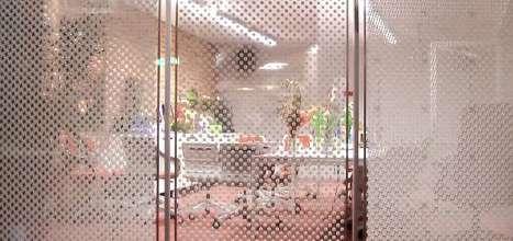
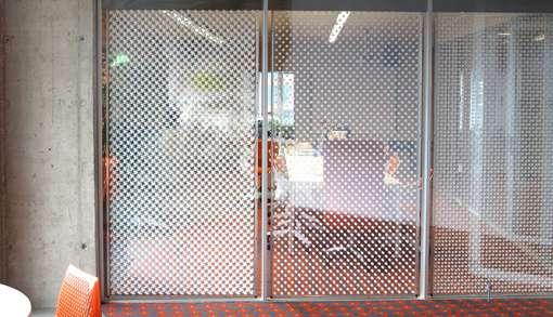
71 Light
Fig 2.1w : Three units of fritted pannels combined together to control the opacity according to the function. Changing to opaque as to detach the visual connection in the spaces for privacy in conference room, and increases visibility when acting as a display element for the museum.
Fig 2.1x : Depending upon the sensing of light the fritted units show the degree of visibility in the space.
Working of Adaptive fritting patterns pannel in a module :
Frit pattern layers moving from 180 - 1080 - 1980 - 2880 with respect to the fxed frit layer. Hence at 00 screen becomes transparent as frit pattern alings to overlap each other and at rotation of 180 frit patterns diverge from each other becoming opaque.
Frit pattern layers moving from 450 - 1350 - 2250 - 3150 with respect to the fxed frit layer. Hence at 00 screen becomes transparent as frit pattern alings to overlap each other and at rotation of 450 frit patterns diverge from each other becoming opaque.
72 LAYER 1 LAYER 2 LAYER 3 LAYER 4 LAYER 5 LAYER 1 Fixed Frit Pattern Moving Frit Pattern
Light
Table showing the specifcations as well as purpose of adaptive fritting in the builtforms:
Projects of Adaptive Fritting :
At Gund hall in Harvard GSD2009
At Wyss Institute in Harvard University2010
Manifestation in interior space : incorporated in window of curved wall. in the main entrance sliding glass door and an adjacent moving glass partition wall.
Types Fritted pattern : small circular dots of brown color. Door -gradated with pattern of hexagonal dots. Window - square colored pattern .
Adaptive Fritting surface area :
8.6 sq. meters of adaptive surfaces.
Dimensions : Window - 1.2m x 7.2m
Door - 12 sq. meters of adaptive surfaces. Wall - 21 sq. meters of adaptive surfaces.
Door - 3.5m x 3.5m
Window - 6m x 3.5m
Material : Acrylic screens, Aluminum frame Door and Window - Digital print on clear acrylic screen, laser-cut acetal channel, stainless steel, glass at front and back.
Control system : Each panel driven by a servo motor with custom array control.
Each panel driven by a servo motor with custom array control.
At AHHAA Science Centre Estonia2011
in a movable glass conference room wall with adjustable opacity.
white circular dots in an acrylic sheet.
8.6 sq. meters of adaptive surfaces
Wall - 3.6m x 2.4m
Acrylic screens, Aluminum frame.
Each panel driven by a servo motor with custom array control.
Operated units : Curved window - 6 Door - 12, Window - 12 Wall - 3
Purpose : Functional - pannels programmed to form a dynamic feld where light transmission, views, and enclosure continuously adapt and change. As the panels transform, the visual efect is of sparse dots blossoming into an opaque surface.
Functional and artictic approach to explore the merging of 3-dimensional design with 2-dimensional artwork which focus on to abstract the images and apply a custom color palette complementing the Institute’s interior design and architecture.
Functional -It imbues conference room occupants with the ability to control their level of privacy. Artistic - an intelligent and inviting display of technology for museum visitors.
73
Case Study 2.2: Intelligent surfaces - Tessellate
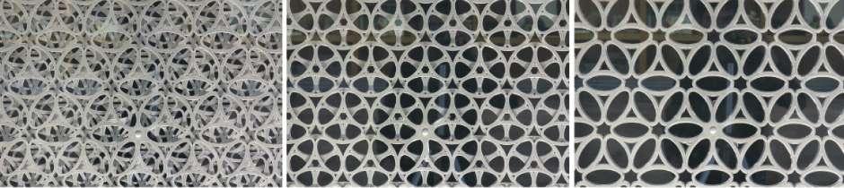
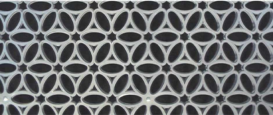
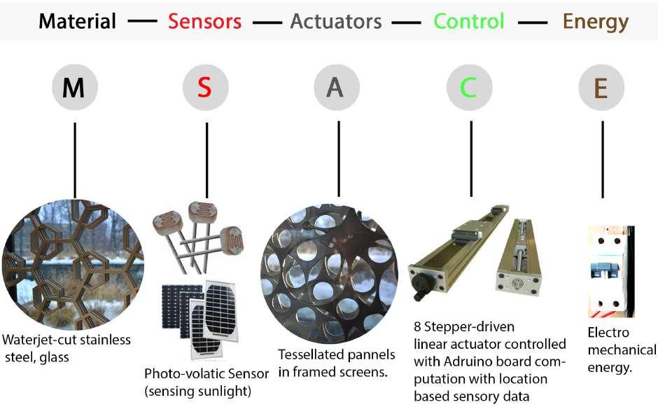
74
Fig 2.2 a : Elements used in tessellate interactive system.
Fig 2.2 b : Stages of tessellate module aliging and diverging to control the light in interior.
TESSELATION: Continually evolving surface, pattern and opacity.
‘A building will realize signifcant performance benefts if its facade or skin can physically respond to changes in the environment’- Chuck Hoberman.1
Tessellation is another kind of intelligent surface as well as interactive system designed by chuck Hoberman. Intelligent surfaces are kinetic surfaces, a system that physically adapt to change in daylight, solar gain, air fow, privacy and views by changing their confguration.
The adaptive tessellation is a self-contained modular framed screen system whose perforated patterns can continually shift and evolve kinetically to become a shading system. It is designed for glass and glazing systems, partition walls, roofs, and a multi purpose facades and awnings in exterior as well as in interiors.
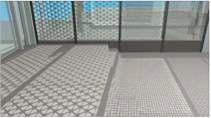
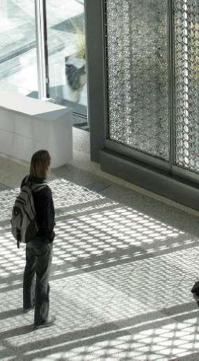
Tessellate consists of a series of stacked panels that can be constructed of various metals or plastics. As these layers overlap, the result is a complex geometric pattern similar to kaleidoscopic visual display of patterns aligning and then diverging into a fne, light- difusing mesh. Hoberman says “When a building physically transforms, it in turn transforms the viewer’s surroundings through spatial impact or shifting play of light from kinetic surfaces.”2 [Fig 2.2 d,e]
Tesselation works on the same system of sensors ,actuators and controls. This system helps in movement of tessellate modules.[Fig 2.2 a,b,c]
Actuator
Tempered Glass
Steel Frame
Tessellate Module
Tempered Glass
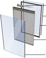
75 Light
Fig 2.2 c : Exploded view of tessellate interactive system in layers.
Fig 2.2 d: Rendering of tessellate module in interior controlling light.
Fig 2.2 e: Tessellate module controling light in interior by diverging and aliging, through sensing the current interior temp as well as glare of sun.
1. Climate control/ intelligent façades - Design Build Network.pdf
2. Tessellate™ Adaptive Façade System.pdf
Much like the leaves on a tree, Tessellate can at once create the efect of dappled sunlight during the summer months, and allow direct light to stream in during the winter.3
The frst building to utilize Tessellate is the Simons Center for Geometry and Physics at the State University of New York at Stony Brook. The installation completed on November 2nd, 2010.
Tessellate serves building both as the building's artistic centerpiece and as a functional piece of shading seamlessly integrated within its south facing glass facade. . Hoberman designed each panel to have a unique geometric pattern of perforations that mirrors the research focus of the building’s resident scientists and mathematicians. [Fig 2.2 g(a,b),f]
This kinetic screen along the southern glazing of a lobby creates an artistic efect of light in the lobby like "dappled sunlight coming through leaves," says Hoberman, who helped design the system. Tessellate is made of multiple overlapping layers of perforated metal panels, the movement of which creates complex patterns. As these patterns align and diverge, the visual efect is of sparse geometric patterns such as hexagons, circles, squares, and triangles that shape into an opaque mesh. The Simon center facade consists of four modules with diferent patterns such as small and big hexagons, circles, triangles and square grids. Captivating viewers, Tessellate covers 400 square feet and provides the building with the functional capacity to a dynamic opacity transformation.4 [Fig 2.2 h,i]
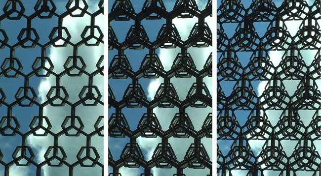
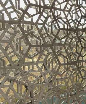
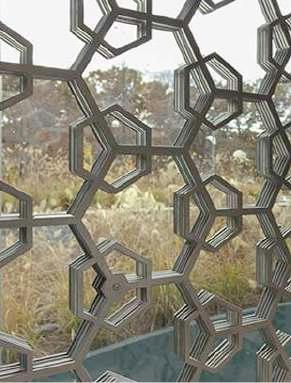
76
Fig 2.2 f: Showing diferent stages of tessellate hexagon module in SCGP, showing change in alignment to control light in interior.(left to right.)
Fig 2.2 g(b) : when hexagon module is fully diverged prividing shade for interior.
Fig 2.2 g(a) : hexagone module is aligned.
3. http://www.adaptivebuildings.com/simons-center.html.
4. http://www.adaptivebuildings.com/simons-center.html.
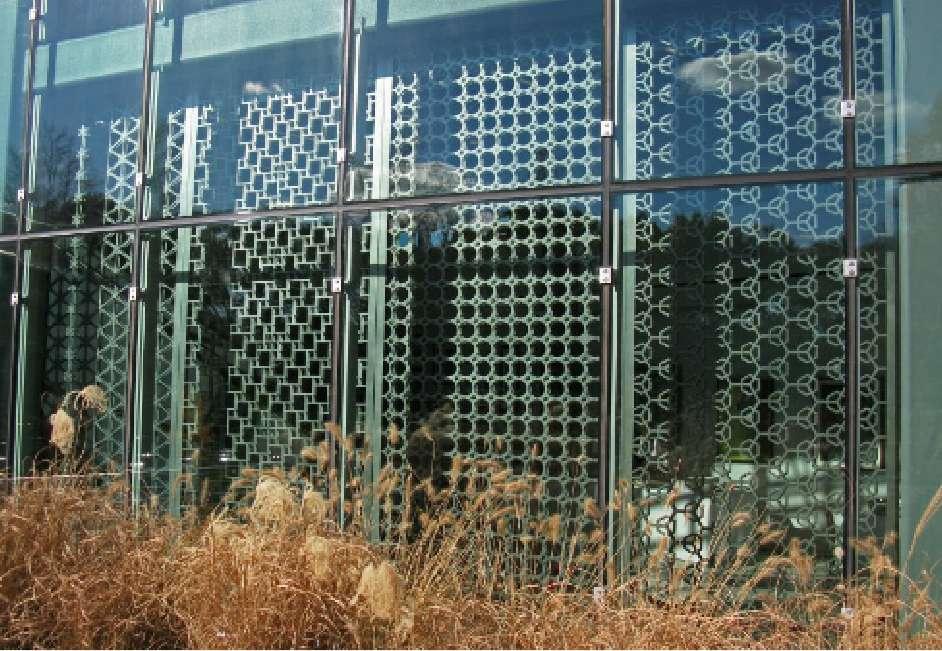
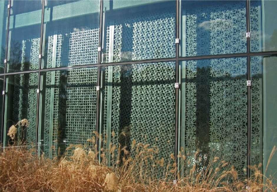
77 Light
Fig 2.2 h : At the southern facade of SCGP ,when all the tessellated modules are aligned, providing light in interior.
Fig 2.2 i : At the southern facade of SCGP ,when all the tessellated modules are fully diverged providing shade in interior.
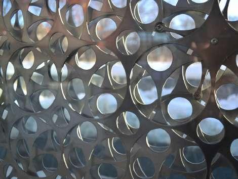
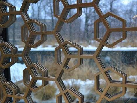
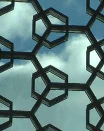
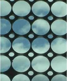
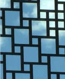
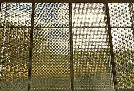
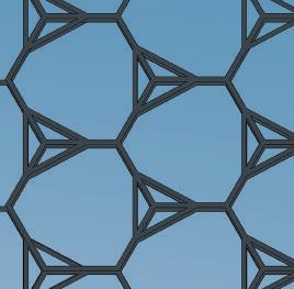
78
Hexagon Module
Circular Module
Square Module
Traingular Module
Screen 1
Screen 2
Screen 4
Screen 3
Screen 1- Hexagon module
Screen 2- Circular module
Fig 2.2 j:
Fig 2.2 k:
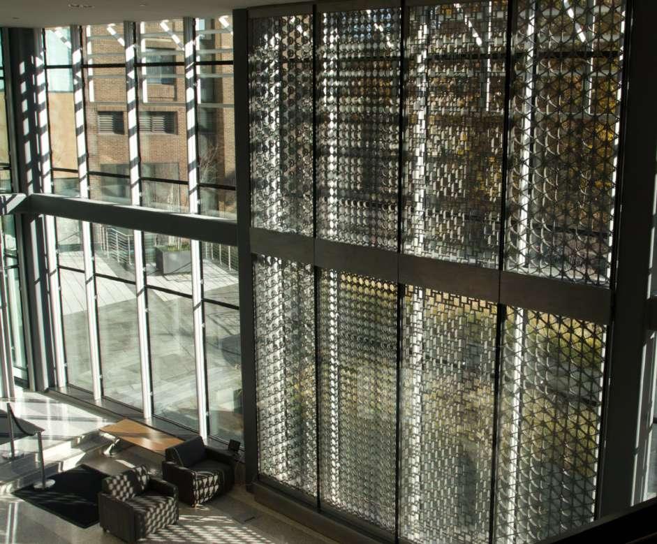
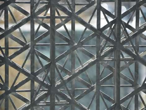
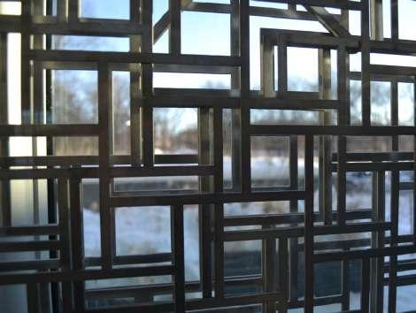
79 Light
Screen 3- Square module
Screen 4- Triangular module
Projects of Tessellate Type Tessellate area Dimensions Material Control System Operable units Purpose Stony Brook University, New york, USA Indoor South Facade. 38 sq. meters 5.6 m wide x 6.7 m tall Stainless steel, glass. Linear actuator 8 units To control light and heat.
Fig 2.2 l: Interior view of southern facade at SCGP building, a facade consists of Tessallated screens with four diferent module. Each module consists of two screens covering double height which controlls the interior light condition of the building.
Tessellate consists of fve metal laser cut panels including a steel frame where all the panels are stack together. Each one of Tessellate modules runs only on one motor. This motor in a module is controlled by a computer processor, which could be programmed for several objectives such as light, heat etc. in response to changing environmental conditions.
Tessellate consisting fve geometric pattern layers, from which frst and last layer are fxed with glass in a frame hence are not movable. Second, third and fourth layer move according to the sensory input given by the sensors which is based on shape grammar rules which are linguistic-based system approach, the logic controller picks and processes these rules, shape rules defnes transformation for a current shape. All of the modules, the movable panels move in a triangular direction away from the major fxed main grid performing a complex geometric patterns similar to kaleidoscopic patters. The pattern has an overlapping Arabic motifs, Crafts fabrics, and optical art illusions. [Fig 2.2 n,o,p]
LAYER 1
LAYER 2


LAYER 3
LAYER 4
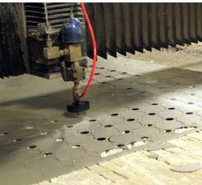
80
Fig 2.2 n: Hexagon tessellate module represented with four diferent colours where red colour hexagon is fxed and blue , green, cyan colour hexagon move away from centre in a triangular direction hence becoming a dense and complex kaleidoscopic pattern, which shades the building interior from sunlight.
Fig 2.2 m: Individual cutting of metal pannels.
Fig 2.2 o: All the layers aligned together to give maximum light in interior.
A.The three layers initiate diverging in traingular direction away from the fxed red layer, to control the present light condition in interior.
B. All the layers diverge towards maximum condition in traingular direction away from the fxed red layer, to control the present light condition in interior.
C. The divergence of the layer reaches towards their maximum condition acting as an element which provides shade in interior.
81 Light A B C
Fig 2.2 p:
Pattern has a central axis that ties its units together structurally, it also considered to be a pivot point regarding pattern machinery, and it is a reference for defning the movement of other layers, each one of pannels has a pin, and the pattern changes as the pin moves.This kinetic pattern is based on a two-dimensional movement, it moves only in X and Y direction.6 [Fig2.2 q]
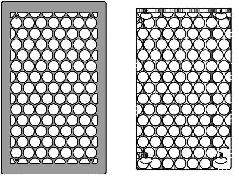
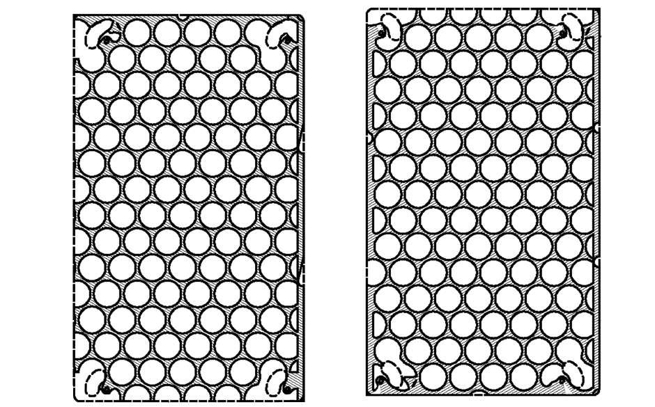
82
6. Jamil_Alkhayyat_Dissertation-libre.pdf, pg:52,62.
Pannel : 1
Pannel : 4
Pannel : 3
Pannel : 2
Fig 2.2 q: In SCGP , the circular module panelling stacked together by a pivot point.
Tessellate is controlled using location-based sensory data to respond to light and weather conditions and fully integrates into the building management system. For instance, when high levels of direct light are detected, the metal panels diverge, and their patterns completely overlap, blocking the sun’s rays. The sensors are programmed in a variety of ways to maximize energy efciency and savings.7
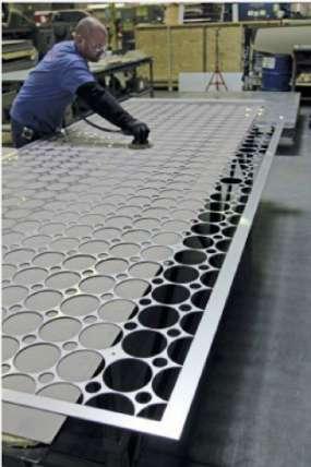
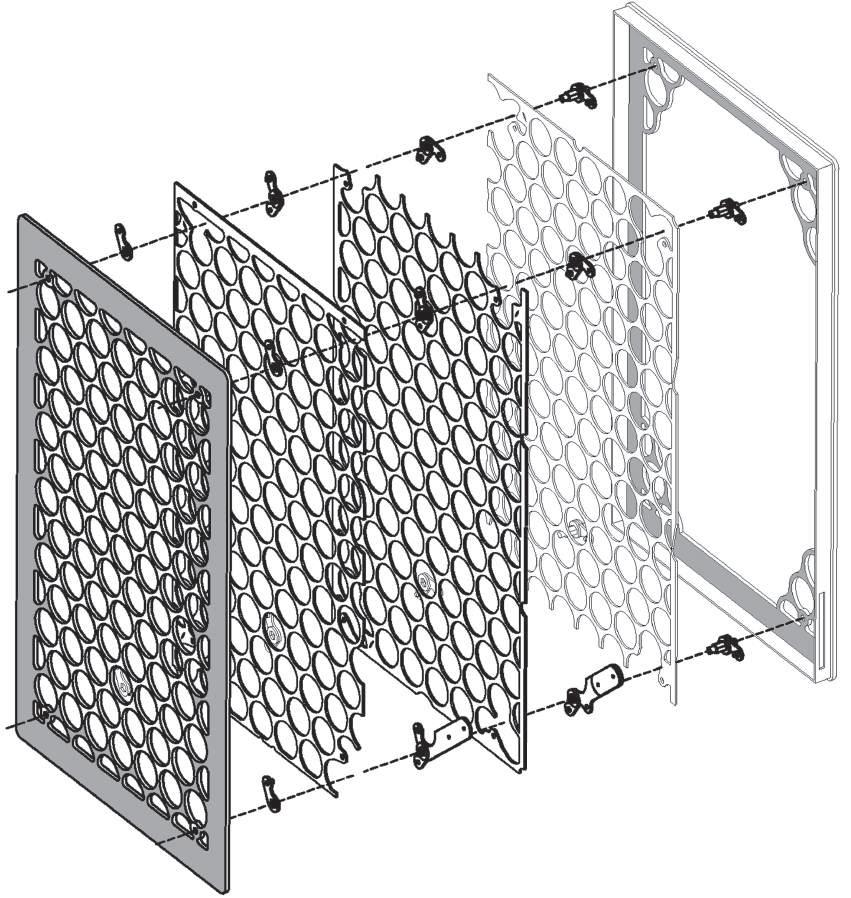
As motors and actuators shift the panel’s positions, the individual units become transparent or opaque. Shielding a building’s occupants from the sun, depending on the season and time of day. Hoberman says each unit is individually controllable. When you install them in a feld of hundreds or thousands across a building facade, then you can see it as an interactive system. If a shadow falls across the building, you might notice a small region open up to bring in more light or see a gradient efect that sweeps across the structure.8
7. Jamil_Alkhayyat_Dissertation-libre.pdf, pg 53.
83 Light
[Fig 2.2 s]
Pannel : 1 Pannel : 2 Pannel : 3 Pannel : 4
Screen 2
8. A. Zahner Company and Adaptive Building Initiative Unveil Tessellate at the 2010 Greenbuild Expo | R.pdf, pg 4
Fig 2.2 s: Exploded 3d section of circular module screen of SCGP.
Fig 2.2 r: Bufng of individual pannels.
Motorized pin
The shifting geometries are also designed to be appealing to the eye, creating a kind of ‘functional artwork’, Hoberman says 9. The interaction between Light play and shading allows a tranquil interior. This kind of interaction also creates a massive impact on the buildings’ footprint and deploys enough shades to prevent ofces from overheating.
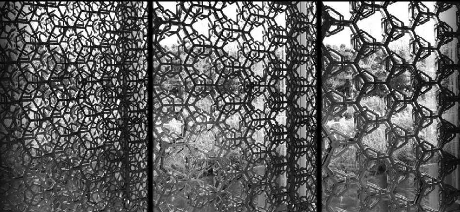
According to ABI, patterns opacity can varies from ten to eighty fve percent, also Its speed can be adjusted to track the sun or responding to environmental aspects like energy usage, solar gain, and daylight levels.10 [Fig 2.2 t,u,v,w,x]
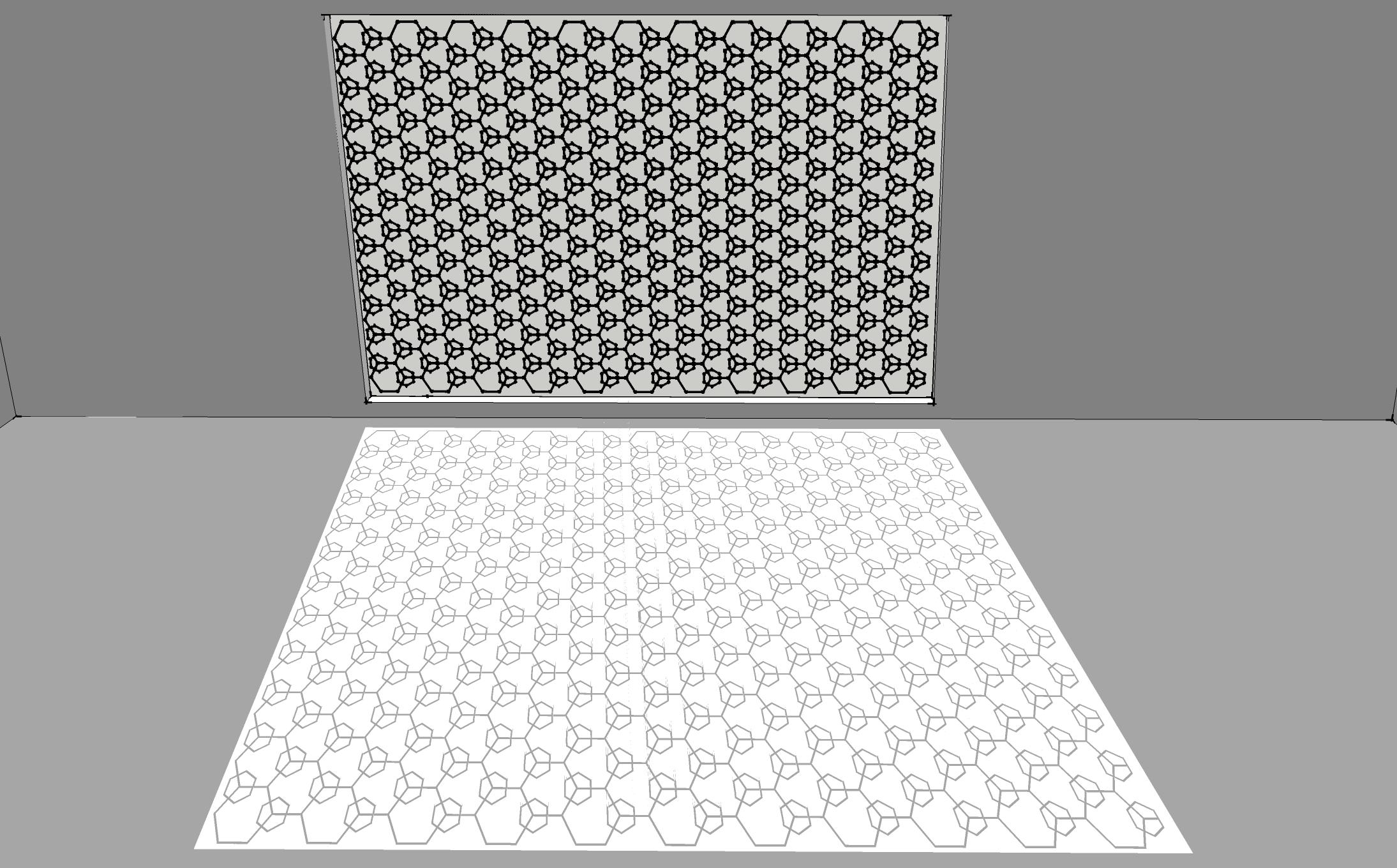
9. http://www.hoberman.com
10.http://www.adaptivebuildings.com
84
Fig 2.2 t: Geometry shifting in hexagonal tessellate module creating an artwork as well as contolling light in interior.
Fig 2.2 u: Tessellate module aligned together to provide light in interior.
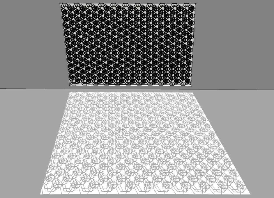
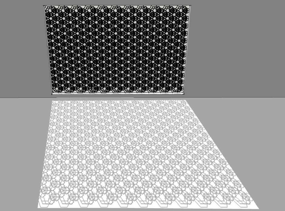
85 Light
Fig 2.2 v: Tessellate module diverges to control light in interiors.
Fig 2.2 w: Tessellate module diverges to change in patterns, becoming an artifact as well as controls light in interiors
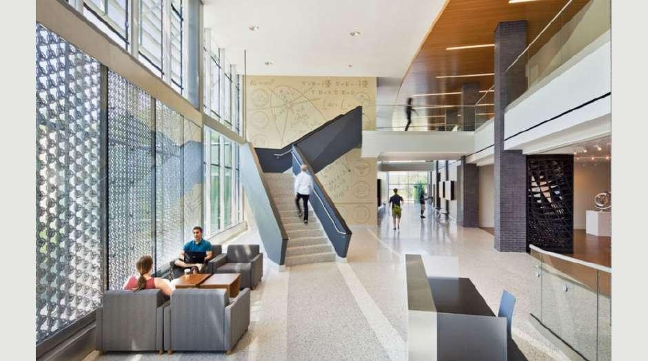
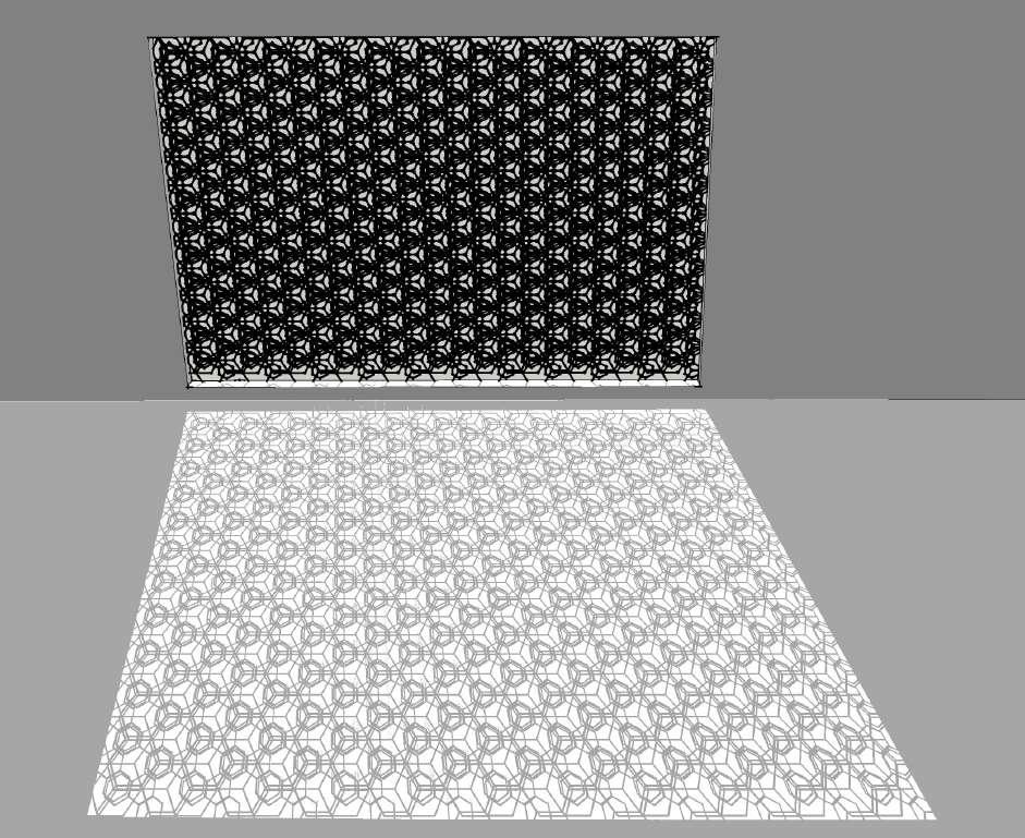
86
Fig 2.2 x: Tessellate module diverges maximum to control light as well as glare in interiors.
Fig 2.2 y: Two interactive systems in SCGP, at left southern facade consists of tessellation and right is artistic steel gate for art gallery.
A second, installation, an artistic steel gate, was created for an adjoining art gallery. After gallery hours, the gate’s static perforated steel panels create an undulating feld of curved, intersecting lines. By day, these panels cleanly fold together to create a three-dimensional sculpture within the gallery. Parametrically generated by the planar slicing of a twisted cubic form, the stacked form creates twisting, open volumes - a play on positive and negative space, with dynamic sight lines that change as visitors walk around it.11 [Fig 2.2 y, z, z1, z2]
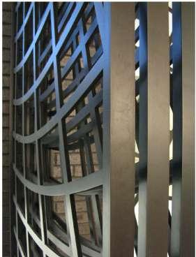
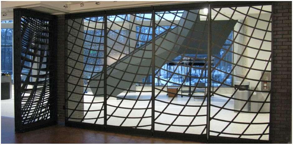
Both installations were delivered through Hoberman venture Adaptive Building Initiative and its network of partners.
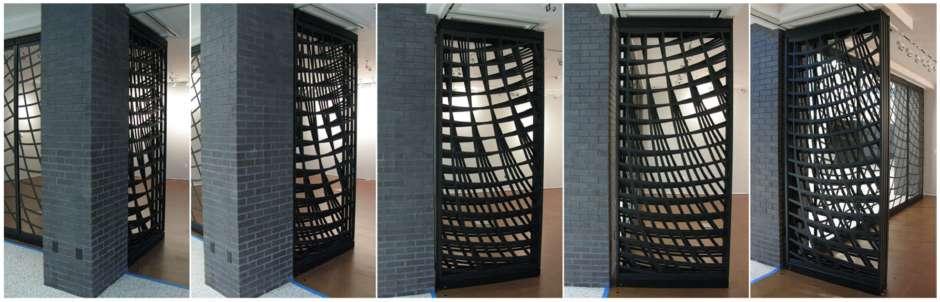
87 Light
Fig 2.2 z : Steel gate at SCGP.
Fig 2.2 z1 : Steel sculptural gate at SCGP, which stack together during the day and unfolds during of hours.
11. HOBERMANSOQ adaptive initiative.pdf, Pg 13.
Fig 2.2 z2: Stacking together of steel gate at the art gallery, creating diferent patterns.
12,13,14.
Solar shading, Tessellate’s primary function, is an important consideration when designing an energy-efcient building envelope. It is a signifcant design challenge to reduce a building’s energy consumption while maintaining daylight rendering that preserve views and promote a healthy internal environment.
Tessellate’s ability to shade adaptively addresses these concerns and improves a building’s energy performance by dynamically adjusting to environmental conditions and internal user preferences. More specifcally, Tessellate provides the following energy savings:
overall energy consumption by 6%.
15-20% over fxed shading.
levels, Tessellate can provide 12-14% more hours per year when day-lighting systems can be used over artifcial lights, as compared to fxed shading or traditional blinds.
higher daylight transmission and improved color rendering capabilities to be specifed while meeting or exceeding ASHRAE 90.1 2010 SHGC values.12
In addition to its functional benefts, Tessellate strongly enhances interior as well as architectural design. Tessellates patterns are created from a collaborative process of design and engineering, balancing the relationship between pattern, movement, geometry, and scale. ABI President and cofounder Chuck Hoberman explains that when designing Tessellate, integration with the building, and design fexibility are as carefully considered as its technical. 13
He says: “Shading, day-lighting and solar gain management are critical to a building’s energy performance. The systems that address these needs should be as carefully designed as the building itself. They must be at once beautiful and functional.” 14
By contrast, with a responsive design, “the building will optimize itself to changes in the environment” he says, “that optimization results in improved energy efciency and environmental performance but, equally importantly, in enhancing comfort.”
88
A. Zahner Company and Adaptive Building Initiative Unveil Tessellate at the 2010 Greenbuild Expo | R.pdf pg 2,3
Multidisciplinary team has also conceptualized to implement Tessellate technology into a dynamic perforated screen system that regulated light and solar gain. A building is planned for 2014 construction. Te architectural frm , WORKSBUREAUTM, has completed the detailed design for twin luxury spas which will become the gateway to the King Abdullah fnancial district in Riyadh.
Each building will be wrapped in a perforated titanium rain screen, incorporating the kinetic tessellate system. Tis tessellate system will adjust its opacity continuously in response to changing environmental conditions such as temperature, moisture and light. Te size of each panel will be 5.4m high and 6.7m wide which will be controlled by 8 stepper driven motor linear actuators.[Fig 2.2 z3, z4, z5]
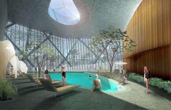
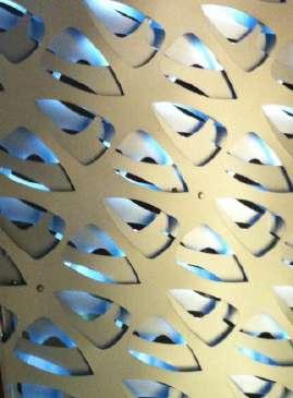
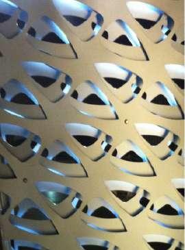
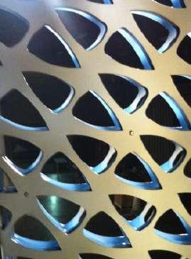
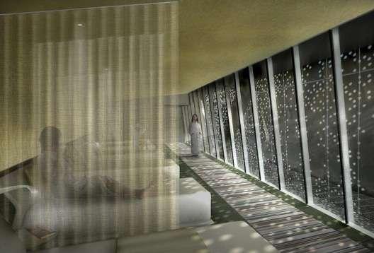
89 Light
Fig 2.2 z3: At the back titanium tessellate interactive system controlling the glare of sun and temperature inside the building.
Fig 2.2 z4: Tessellate system allows a tranquil interior as well as it also has a massive impact on the buildings’ footprint.
A. Aligned to allow light.
B. Staggered for shade
C. The middle layers move back and forth, creating both shade and light play.
Fig 2.2 z5:
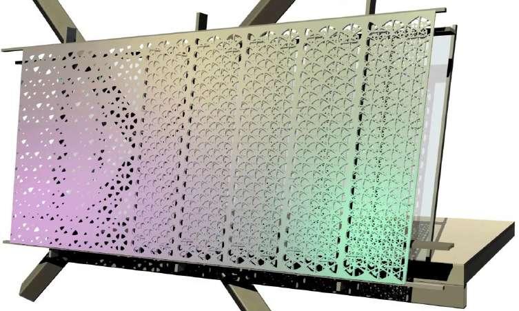
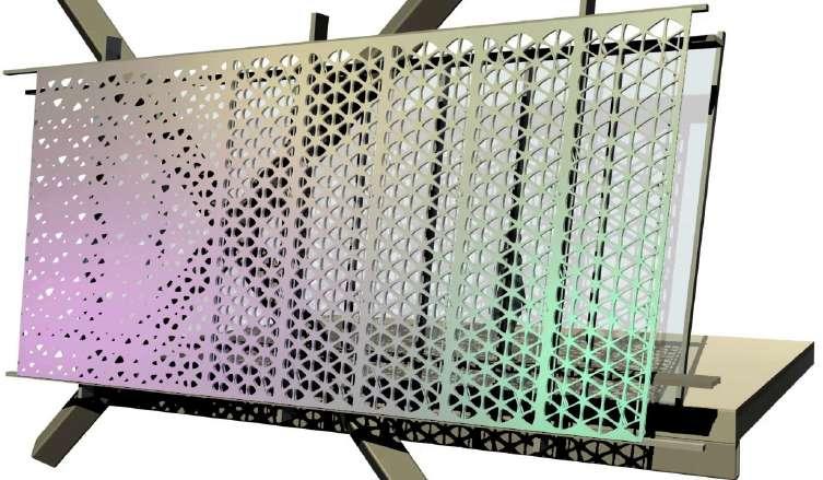
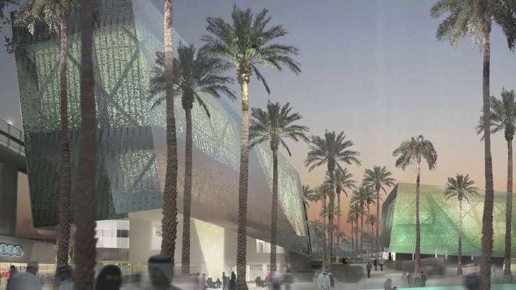
90
Fig 2.2 z6 : Twin spa building with tessellate system facades.
Fig 2.2 z7 : Mockup of tessellate facade when viewed from outside and pannels fully diveged to provide shade inside the building.
Fig 2.2 z8 : Mockup of tessellate facade when viewed from outside. Tesselate pannels aligned to provide light into the building.
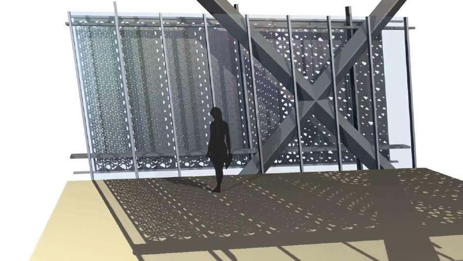
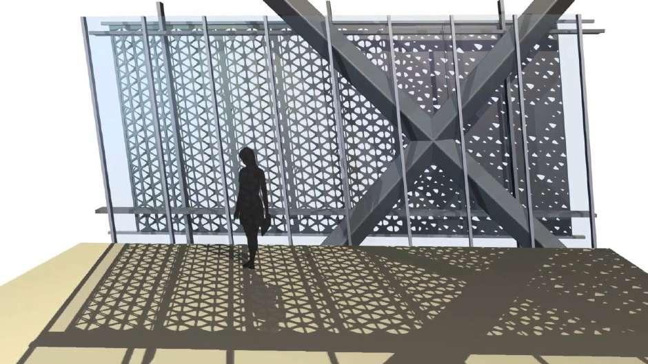
91 Light
Fig 2.2 z10 : Mockup of tessellate facade when viewed from inside. Tessellate facade aligned to provide light into the spa.
Fig 2.2 z9 : Mockup of tessellate facade when viewed from inside. Tessellate pannels diverged to control light inside the building.
Case Study 2.3: Intelligent surfaces - Strata
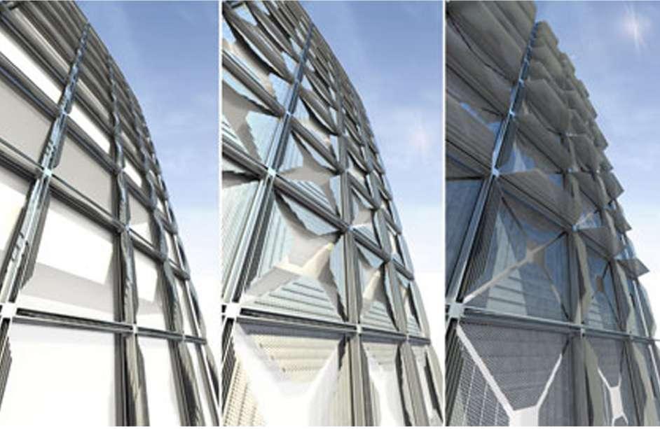
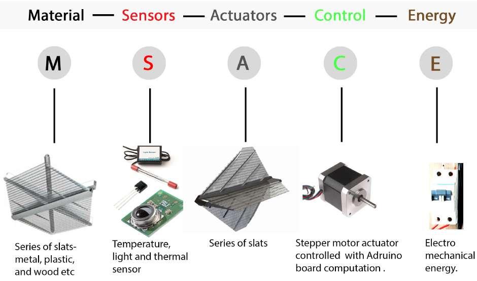
92
Fig 2.3a : Elements used in strata interactive system.
Open Semi closed Closed
Fig 2.3b : Strata system in building changing the facade from open to semi-open to closed, by control interior environment of the building.
A. Fully extended open module
B. Module extended to semi open.
C. Strata module is fully closed becoming visually disppear with in its structure.
STRATA - A building surfaces from nearly nothing.
Strata is another kind of intelligent surface designed by A.B.I. This Intelligent surface continuously interact with its surroundings to control the solar gain, shading, glare, ventilation and air fow with in the building interior to give comfortable environment for the user.
Strata consist of modular units that hide with in a single slender profle when retracted creating opening at normal condition. But when actuation happens due to change in environmental conditions. The modular units extend to form a nearly continuous surface comprised of a series of slats becoming open to semi open to enclose to close. That may be constructed of diferent materials, including metal, plastic and wood. [Fig 2.3 b]
Strata system is well suited to applications for which the shading device is needed to disappear into a buildings underlying structure. The advantage of this system in building is, it visually disappear into buildings underlying structure when retracted being a part of the building. Strata can be applied to the building facades, roofs, and awnings. Strata can also used in building skins and also as a partition walls as well as to create enclosure in an open space, and can also be used as an interior free standing structural shades.1 [Fig 2.3 c]
Movement in strata happens when sensor senses the change in environment. These sensors give signal to controller. The controller controls the motion of motors. This motor actuates the unit of a module. Each module is controlled through a single motor resulting into diferent positions of unit such as open to semi-open to semi-enclose to close in the strata. [Fig 2.3 a,d].
1.http://www.adaptivebuildings.com/strata-surface.html
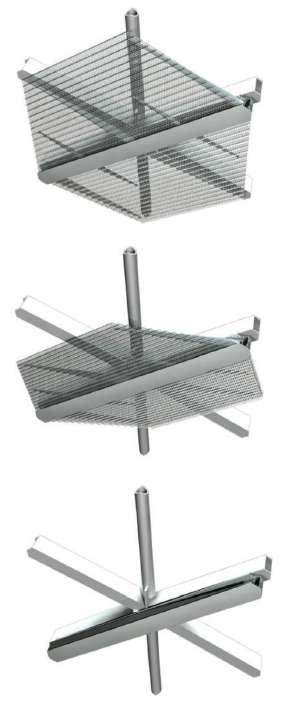
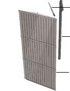
93 Light
Strata Module
Actuator Steel Support
Fig 2.3 c: Strata module
B C A
Fig 2.3 d: Exploded view of strata system.
Strata have been incorporated in new Campus of Justice in Madrid, Spain. The City of Justice is a largest single site dedicated to Law Courts in Europe. Foster and Partners has designed two distinct circular buildings, the High Court and Appeals Court. Both the building has been designed to minimize unwanted solar gain, while allowing natural daylight inside.2
Here strata are used as shading units. In the building of Appeals Court, shading units are used in the central atrium as well as at the eight peripheral atria. [Fig 2.3 e,f,g]
2. http://www.adaptivebuildings.com/city-of-justice.html
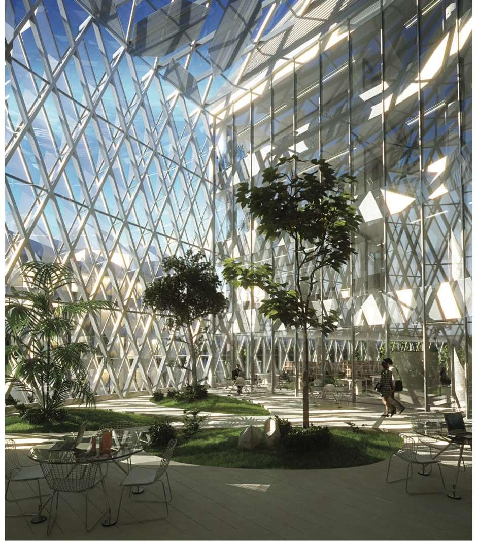
94
Fig 2.3 e: Strata units providing shade at one of the peripheral atria in appeals court.
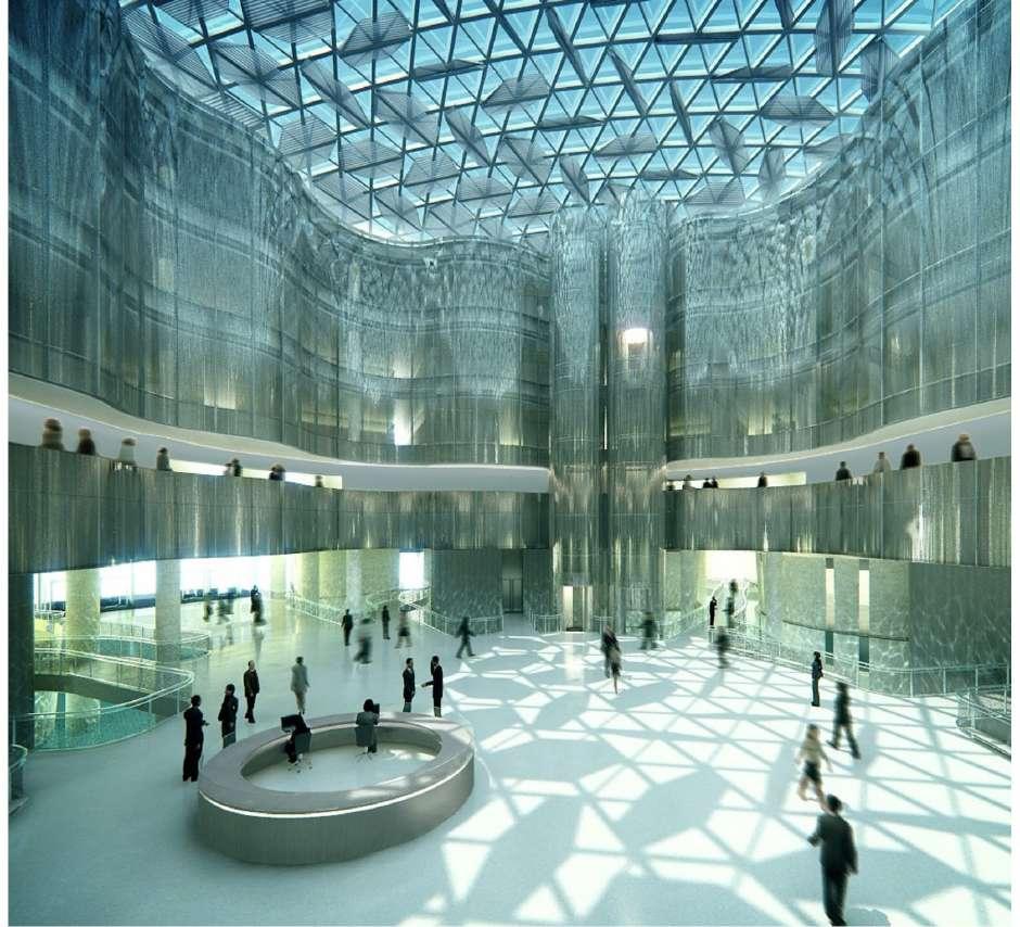
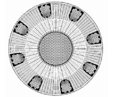
95 Light
Eight pheripheral atria of appeals court .
Central atria of appeals court.
Fig 2.3 f: Plan of appeals court.
Fig 2.3 g : Strata units providing shade at central atria of appeals court by controling unwanted sun light.
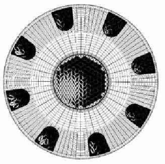
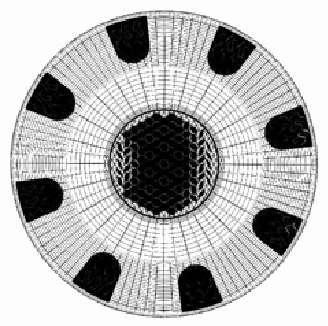
96 6:00 AM 8:00 AM 10:00 AM 12:00 PM 2:00 PM 4:00 PM
Fig 2.3 h: Plan of appeals court representing the shading provided by strata units from 6:00 am to 4:00 pm through sensing the environment.
In each building when the strata system is extended, it covers the triangulated roof grid. And when retracted, the strata profle disappears into the structural profle of the roof. During the day, each strata shading module senses the light condition, If light level is more in the atrium than each strata module will control the level of light by extending and covering the triangulated roof grid. And when the light level in the atrium is normal than strata module will retract and disappear into the structural profle of the roof. Hence controlling the light rendering in the atrium.3 [Fig2.3 h]
In High Court building the shading unit is used at the trapezoidal central atrium. [Fig2.3 i,j,k]
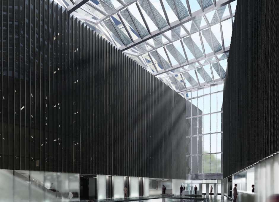
97 Light
3. http://www.adaptivebuildings.com/city-of-justice.html
Fig 2.3 i : Strata units providing shading at the trapezoidal central atrium of high court building.
Strata module
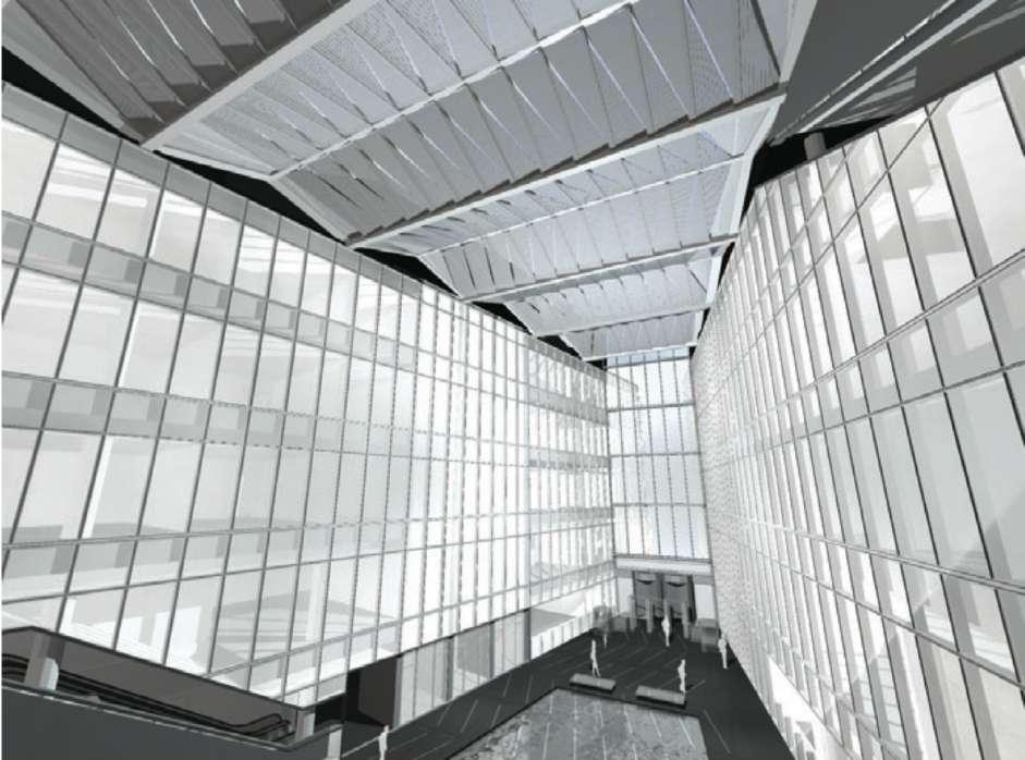
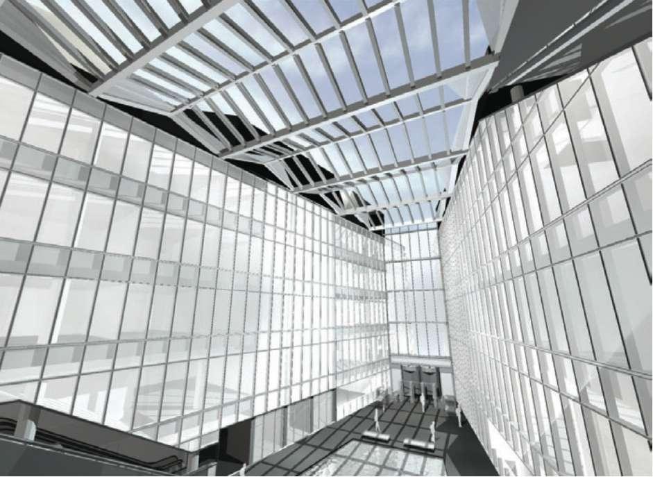
98
Fig 2.3 j: Strata units fully opened providing shade to the atrium of hight court.
Fig 2.3 k: Strata units fully closed providing optimum light to the atrium of the hight court.
Like in a daylight, ‘it is difcult to walk in desert while to walk in a forest because leafs in a forest became shading elements’ like wise atrium without strata shading device will become like a desert which through strata shading device will give feel like walking in a forest. [Fig 2.3 l]
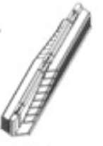
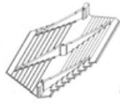
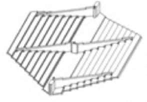
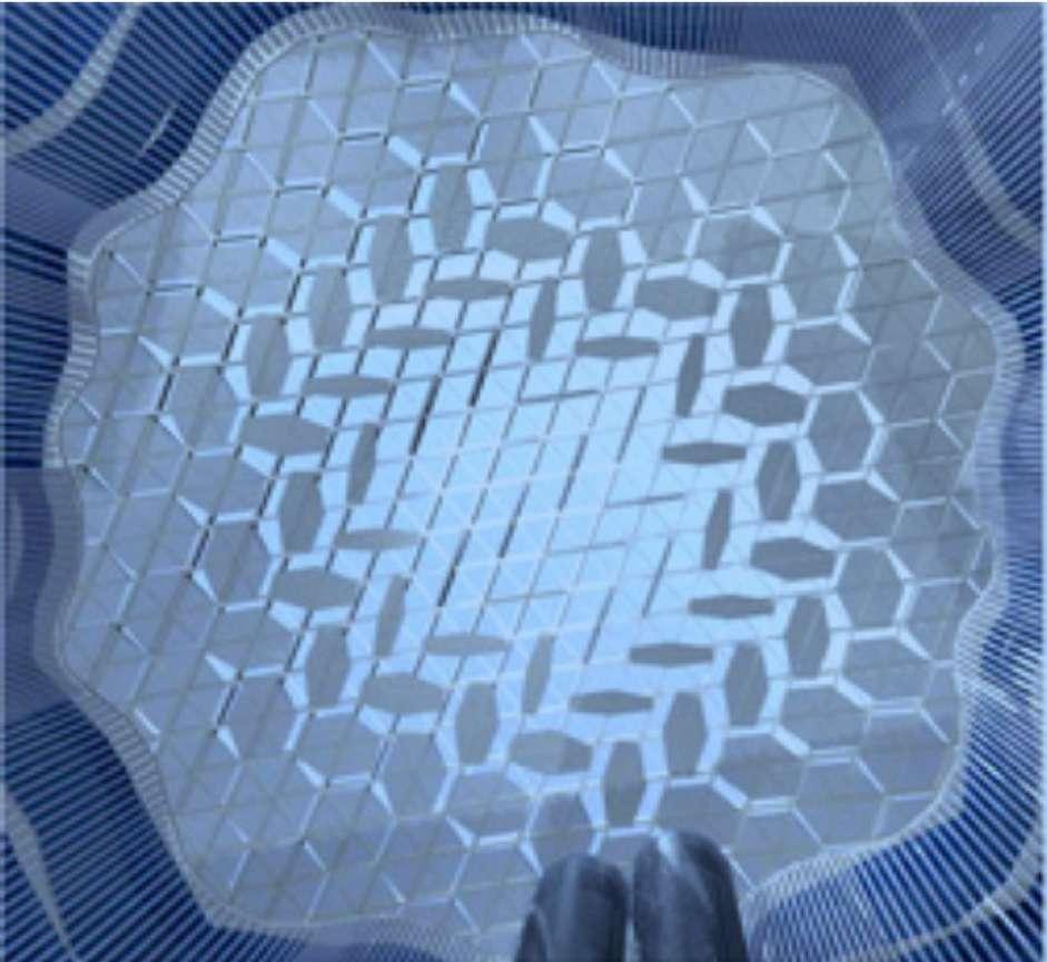
99 Light
Open Semi-open Closed
Fig 2.3 l: Central atrium of the appeals court covered with strata units which controls the temperature as well as light in the atrium by sensors and actuators.
Motorised pin
Fig 2.3 l1: Mechanism of strata module: 1. A motorised pin with two support pivot pin. 2. 16 slats with 2 individual pivots.
Slats
A.B.I has also conceptualized the implementation of strata in a freestanding structural system known as a series of umbrellas. The exhibit ”100 years of construction innovation” commissioned this structure at the building center trust in London.
In this kinetic structure three shading units were created, each having a square plan that transforms into a slender profle through retraction. The shading surfaces are of transparent blue glass and the structural members are constructed from aircrafts aluminium. These shading units can be arranged in many ways like in this it is in square confguration. These can either be freestanding or can also be integrated into the building structure, as a courtyard that can transform from indoor to outdoor.4 [Fig 2.3 o,p]
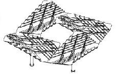
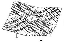
Strata system can also be used as device which can open and close by sensing the users in a public spaces like a door to control the intake [Fig 2.3 n]. And can also be used as a temporary overhead structure to provide shade when four units of strata system is combined together. [Fig 2.3 m]
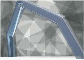
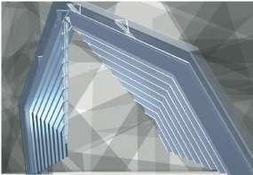
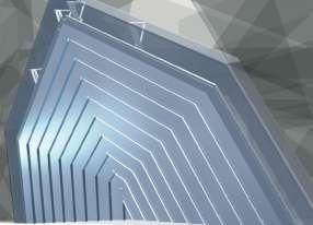
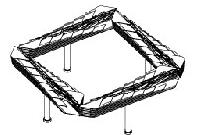
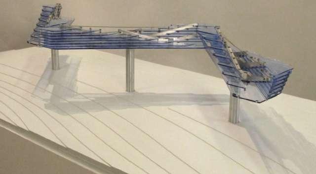
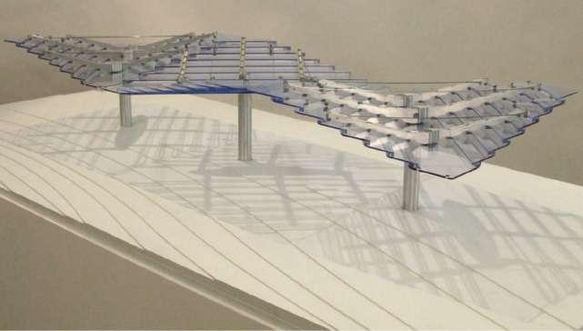
100
4. http://www.adaptivebuildings.com/adaptive-shading-esplanade.html
C. Strata system full closed.
B. Strata system semi opened.
A. Strata system fully opened.
A. Strata system fully opened.
B. Strata system semi opened.
C. Strata system fully closed.
Fig 2.3 m: Strata as a temporary free stading shading structure.
Fig2.3 n: Strata as a door.
Fig 2.3 0: Three strata units combined together to create a overhead and shade when fully opened.
Fig 2.3 p: Three strata units combined together which can closes and opens mechanically and kinetically by sensors and actuators.
A.B.I has also incorporated a sculpture at Museum of Modern Art, New York in 2008 designed by Hoberman Associates. This sculpture named ‘Emergent Surface –a surface which transforms’.5 [Fig 2.3 q]
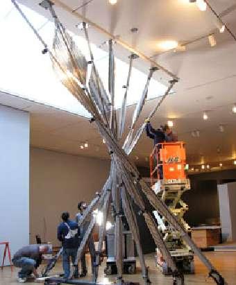
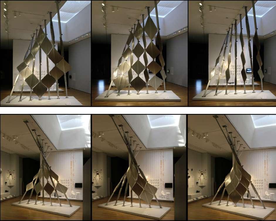
Based on new technologies for adaptive building skins, Emergent surface is a wall that continuously transforms by disappearing and reappearing. As we see the sculpture, the modules together appear as a solid surface with three-dimensional surface at one end. Where as it separates itself into seven slender poles running foor to ceiling. And in between these extremes sculpture shows variety of confguration in the presence or the absence of user.6 [Fig 2.3 r]
This was the frst structure to physically demonstrate the capabilities of strata system in a real scale.
5. http://www.adaptivebuildings.com/emergent-surface.html.
6. http://www.adaptivebuildings.com/emergent-surface.html.
101 Light
Fig 2.3 q: Strata system as a real scale scupture.
Fig 2.3 r : Strata modules showing opening and closing at diferent time as well as from diferent view points by changing patterns all together as an emergent surface.
1.
2.
3.
4.
5.
6.
From understanding such type of experiments, A.B.I has created the Heliotrace facade concept for the Center of Architecture’s competition which aims “To Create an Innovative Curtain Wall Design”. Helio Trace facade means a facade, which will trace the movement of sun (Helio means relating to sun). For this an advanced building enclosure prototype was created that could leverage contextual, environmental inputs to inform a responsive kinetic curtain wall system.7
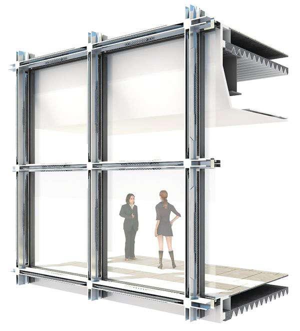
7. http://www.adaptivebuildings.com/heliotrace.html
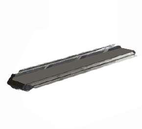
102
Fig 2.3 t: When the heliotrace units are fully retracted during winter months—the system maximizes daylight and allows for passive heating.
Fig 2.3 s: Heliotrace module is closed
This kinetic shading system was developed and integrated into the overall facade by the A.B.I., which incorporates Strata system. SOM’s Sustainable Engineering Studio prepared ecological analyses that leveraged empirical data to inform the position and operation of the kinetic shading system.8
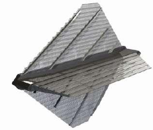
8. http://www.adaptivebuildings.com/heliotrace.html
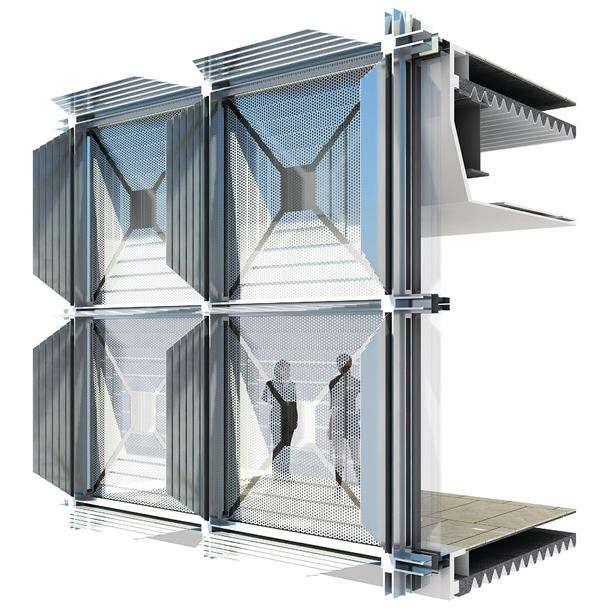
103 Light
Fig 2.3u: heliotrace module is fully opened.
Fig 2.3 v: In summer the heliotrace units fully deployed, the shades control glare and cut heat gain.
Heliotrace facade system combines three diferent systems:
The integration of these three systems, results into an adaptive facade that uses minimum energy to give maximum comfort to the user. This facade give efective shading level up to 78% and an annual solar gain reduction up to 81%.9
Heliotrace facade consists of a high performance glass curtain wall, which is shaded by two exterior shading devices. These two shading devices use strata system. One is an opaque panel at the extreme out, which extends from the mullions, perpendicular to the facade. Second is a 50% perforated panels, which extends parallel to the building envelope (sandwiched between the opaque panel and glass
Building system
Exterior shading
HelioTrace is composed of three systems:
- Exterior shading (both shades that are perpendicular to the building,far left, and shades parallel to the facade, second from left).
- A high-performance curtain wall.
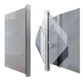
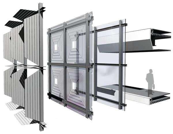
- Complementary M/E/P and building systems.
9. http://www.architectmagazine.com/building-envelope/2010-rd-awards-shading-devices-heliotrace-facade-system.aspx
104
Fig 2.3 x :
Fig 2.3 w: Two types of hoberman linear system : Type 1 - acting perpendicular to facade. Type 2 - acting parallel to facade.
Type 1 Type 2
Type 1
Type 2
Integrated glass curtain wall system.
Symmetrical deployment :
panel). Both the panels can be programmed to show movement responding to solar movement and interior occupancy. [Fig 2.3 w,x,y]

Here energy savings are enhanced by integrated interior systems such as chilled ceilings and beams, and an under foor dedicated outside air system.10
2. Partially deployed shades and screens.
3. Fully deployed shades and screen
Asymmetrical deployment :

1.Partially deployed shades and fully retracted screen.
2. partially deployed shades, partially deployed screens at upper module and fully deployed screens at lower module.
3. Partially deployed shades, fully deployed screens at upper module and partially deployed screens at lower module.
10. http://www.architectmagazine.com/building-envelope/2010-rd-awards-shading-devices-heliotrace-facade-system.aspx
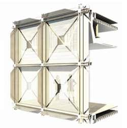
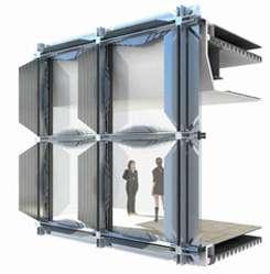
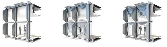
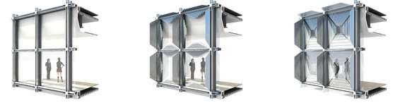
105 Light
Fig 2.3 y : Heliotrace system deployment.
A. Deployment of heliotrace facade in building at newyork in morning.
B A. Deployment of heliotrace facade in building at newyork in evening.
1. Fully retracted shades and screen.
The team performed extensive solar analysis of HelioTrace system components, with three goals in mind:
1. To project from the mullions.
2. Perpendicular to the minimize glare.
3. Maximize daylighting.
4. Control solar heat gain.
When analyzed, the system achieved a 42% reduction in total energy consumption for a New York City ofce tower.11
11. http://www.dwell.com/great-idea/article/heliotrace-robotic-facade.
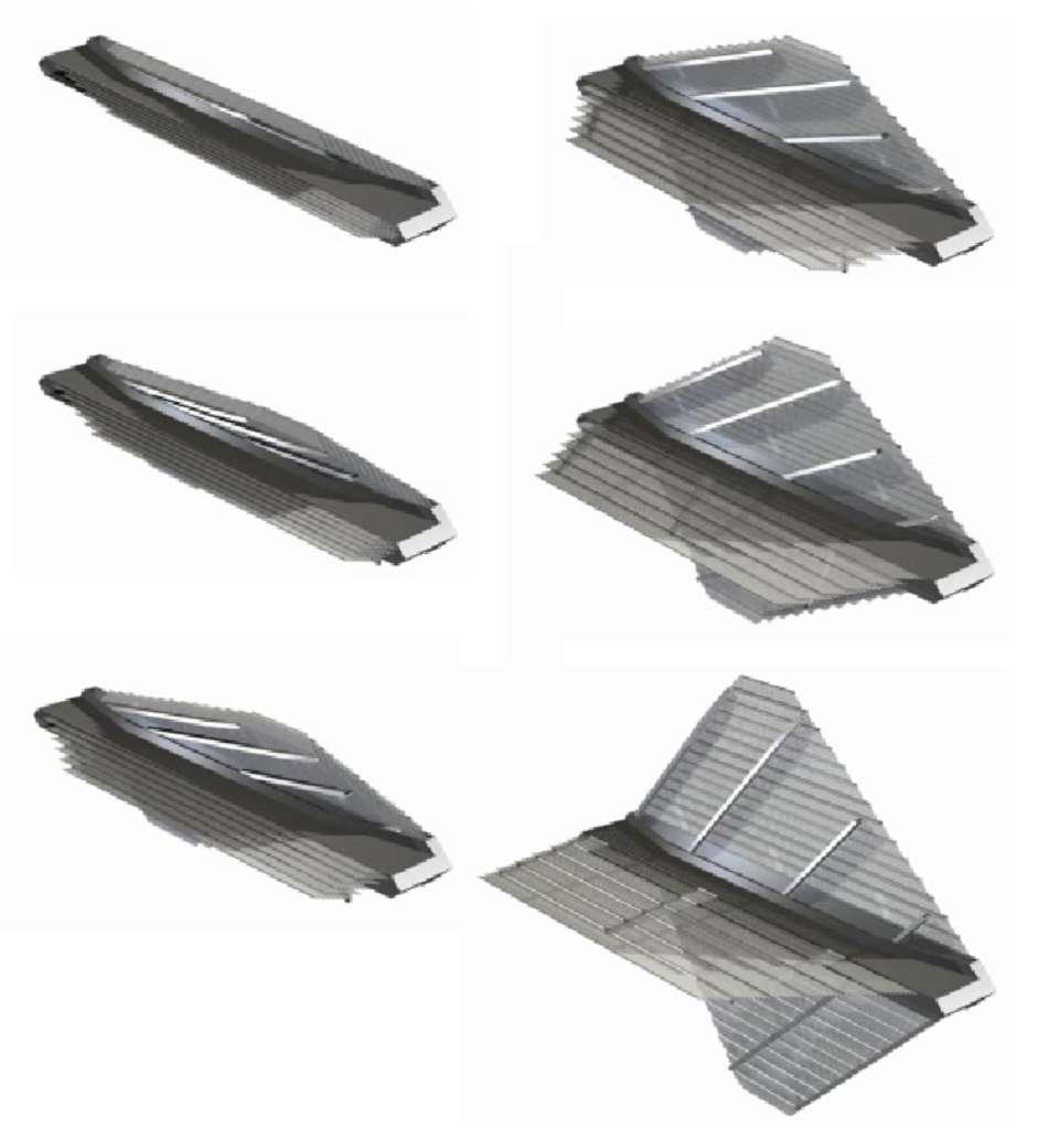
106
[Fig 2.3 z1]
Fig 2.3 z : Deployment of heliotrace module in stages, from fully closed to fully opened.
4 5
1. Fully closed
2 3
6. Fully opened
Comfortable working environment in ofce building helps in long working hours and increase energy efciency :
-By controlling interior temperature through out the day for comfortable working.
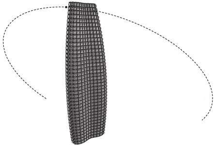
- By keep recycling indore air quality and ventilation.
- Daylight and lighting rendering.
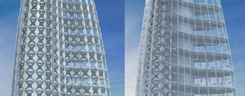
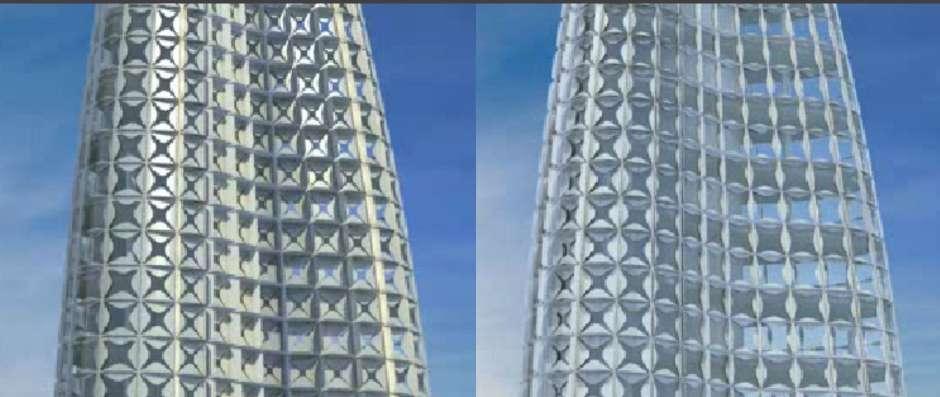
- Active interiors.
Heliotrace interactive system achieves almost all the conditions required for comfortable working in the ofce building.
107 Light 12
pm
Fig 2.3 z1: Heliotrace in centre of architecture building at New York .
A. Heliotrace facade controlling heat gain and light by sensing the current environment and controlling the actuation.
B. Heliotrace facade modules adjusting themselves to give comfortable working environment inside the building.
D. Heliotrace facade, fully retracted as well as deployed to control light rendering and temperature in interiror.
C. Interactive facade providing comfortable light and temperature in ofce building through sensors and actuators.
Case Study 2.4: Intelligent surfaces - Permea
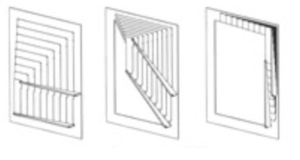
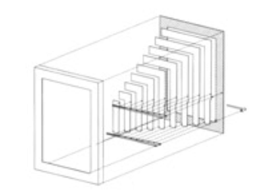
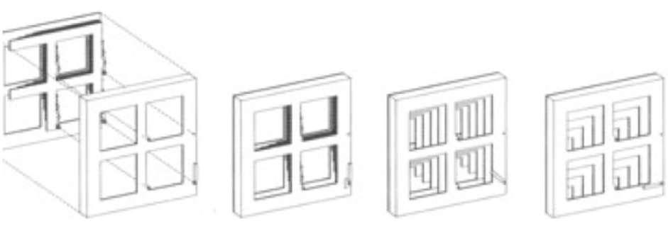
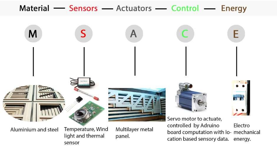
108
Fig 2.4 a: Elements used in permea interactive system.
Fig 2.4 b: Exploded view of permea with diferent stages : A. Fully opened ,to- B. Semi opened ,to- C. Fully closed.
Motorised
A A B C B C 1 3 4 5 6 7 8 9 2
Fig 2.4 c: Permea module incorporated in the grid of window. A. Fully opened. B. Semi opened C. Fully closed
pin
PERMEA - A dynamically permeable surfacing on building facade.
Permea name came from word permeable which means a characteristic of a material or a membrane to allow liquids or gases to pass through it.
A.B.I has created a system named Permea. Permea is a unitized and a self-contained system that controls its permeability varying smoothly between a completely covered and a largely open state.1[Fig 2.4 d]
Permea is designed to create a seal to get protected against dust and debris over large areas and can also be customized for non-rectangular shapes and can also be installed in non-vertical orientations. [Fig 2.4 a,b,e]
Permea being a unitized system can completely hide its layers into the building surface when retracted. It moves parallel to the buildings surface. As Permea can be confgured to control solar gain, glare ,shading , privacy, ventilation and air fow. And also gives protection from Dust and debris. Permea system can be incorporated in facades, roofs, awnings, and buildings skins as well as in blast and fre shields. This A.B.I system can also be transformed into freestanding structural shades. [Fig 2.4 c]
Hoberman Associates and A.B.I developed Permea in several exterior shading at Abu Dhabi’s historic central market in three public square atriums within the retail complex.
1. http://www.adaptivebuildings.com/permea-surface.html
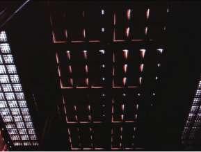
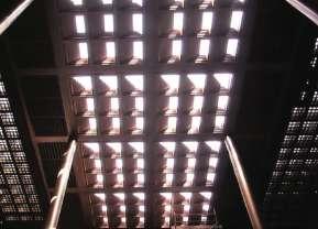
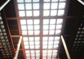
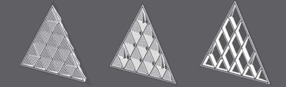
109 Light
A. Permea system fully deployed.
B. Permea system semi closed.
C. Permea system fully closed.
Fig 2.4 d: Permea system used in interiors of the building to control dust, light and heat.
A B C
Fig 2.4e: Permea controlling light ,dust and heat by transforming into opaque surface becoming fully open (A), to Semiopen (B), to fully closed and can also be incorporated in diferent kinds of openings.
Abu Dhabi’s historic central market is one of the oldest sites in the city, where central market is a reinterpretation of the traditional market place and a new civic heart for Abu Dhabi. The project comprises a combination of lower rise, ecologically sensitive level of retail roof gardens, overall forming a new public park and three towers.2
The kinetic design of shading roofs works of on an operable grid. Where the covered shading roof resembles a traditional cofered Islamic roof. And when roof retracted it becomes a slender lattice, which compliments the foster teams design for the fxed shading.3 [Fig 2.4 f]
As Abu Dhabi is situated near desert, Permea system cover the roof at the time of sand storms by extending to seal the roof so that no sand can harm the interior of the building. And on the clear days retracts to control the sunlight into the building. [Fig 2.4h]
Permea system works on the bases of interactive system where sensors plays the role by sensing the current environment and actuators actuate through the controllers. Sensors give data to controllers and controllers after analyzing actuates the actuators. 8 units operate Permea adaptive shading where each unit is driven by a servomotor with custom array control [Fig 2.4 g]. This unit plays the role of actuators and servomotor plays the role of controller. The actuators are made of aluminium and the rest of system is made of steel covering the 1000 square meters of adaptive shading roof.
Adaptive Shading Coverage: 1,000 sq. m.
Control System: Each unit driven by a servo motor with custom array control
Number of operable units: 8
Materials: Aluminum, Steel
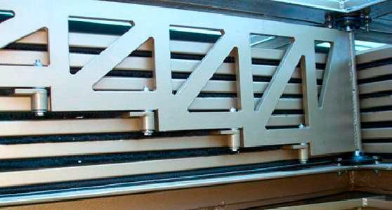
2.http://www.adaptivebuildings.com/aldar-central-market.html
3. http://www.adaptivebuildings.com/aldar-central-market.html
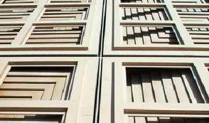
110
Fig 2.4f : Top view of Permea operable shading roof installed at central market.
Fig 2.4 g : Eight operable units of permea controlled through motorised pivotes
Motorised Pin.
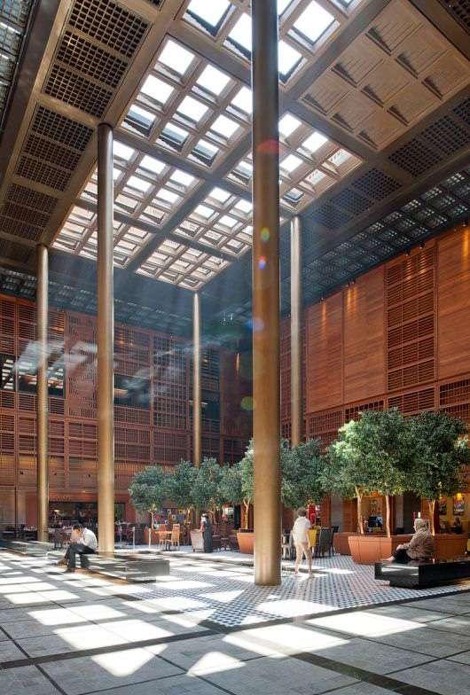
111 Light
Fig 2.4 h: Permea interactive system controlls dust as well as provides sunlight and controlls heat in to the building by sensing environmental conditions and requirements.
In a fnal design competition ’to cover a major central courtyard’ in Abu Dhabi’s international airport, Permea has been incorporated in Hoberman’s Associates responsive dome. [Fig 2.4 i]
The design here binds together the transforming system of Hoberman’s expanding iris domes and the A.B.I intelligent surface - Permea. In the custom operable eye like opening at domes crown, the domes surface is divided into a faceted grid, which incorporates Permea panels. And the overall system together perform becoming open to enclosed space.4 [Fig 2.4 j,k,l]
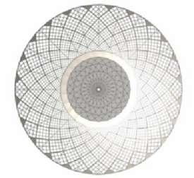
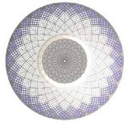
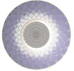
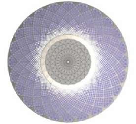
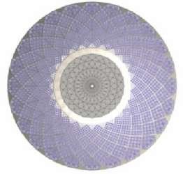
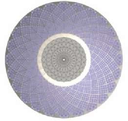
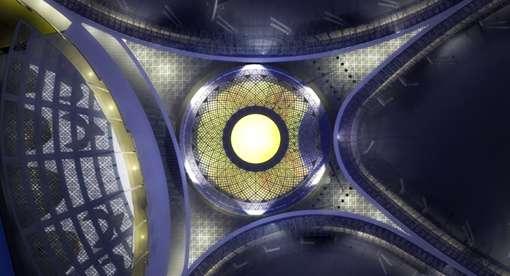
112
4. http://www.adaptivebuildings.com/abu-dhabi-airport.html.
Fig 2.4 i: Plan of Abu Dhabi’s international airport , responsive dome as well as permea surface is fully retracted .
A. Permea surface is fully closed B. Permea surface starts to open from centre of the dome. C. In progress
D. Permea surface retracted till centre of dome. E. Dome is 3/4 open.
F. Permea surface fully retracted.
Fig 2.4 j : Retraction of permea surface at the centre of dome to the periphery, enclosed to open.
A. Complete surface of dome is made with these square grids each gride is again divided into 8 equal parts each part contains eight operable units which opens and retracts back through sensing near environment. And opening of premea surface starts from centre of dome with the help of logic controllers.
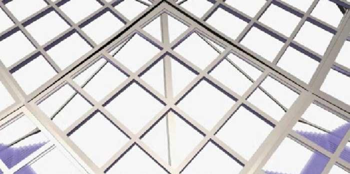
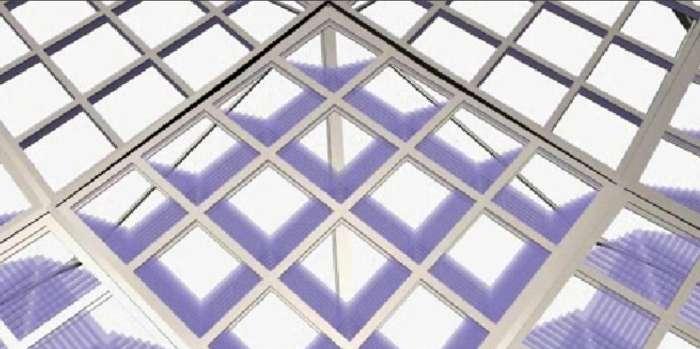
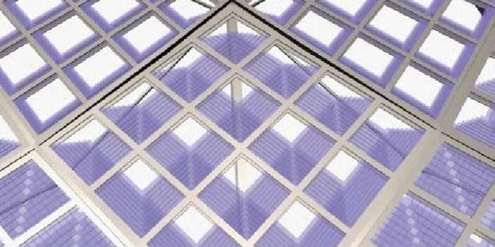
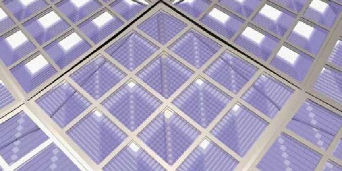
B. Each opening in a grid is equally controlled by individual units as they are connected with each other. Hence each grid has its own operable unit.
C. Each individual grid of permea surface is retracted in diferent time from others.
D. Permea surface is fully retracted from the grid, hence completely hide its layers with in the structure of dome, uncovering interiros or disappearing over head.
113 Light
Fig 2.4k:
Permea system used in centre of dome used scissor mechanism.
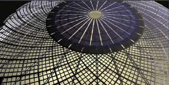
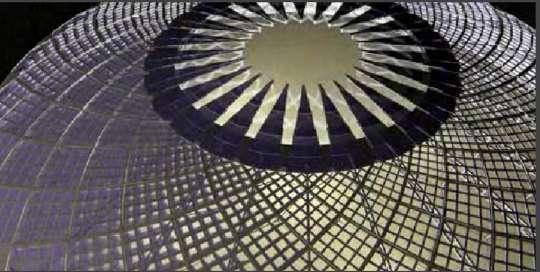
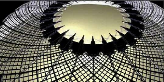
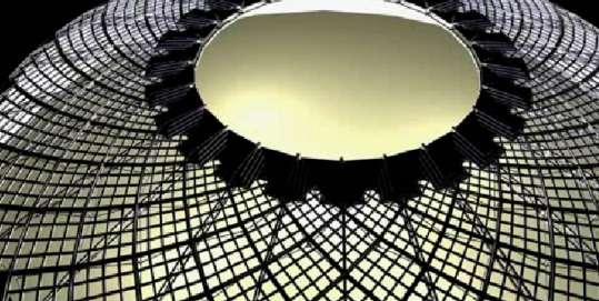
A. Centre of dome is fully opened where permea interactive system is hidden at the boundaries.
B. Permea has reached at 1/4 of the centre of dome and all the layers are connected together so that they close and open together.
C. Layers of permea system at the centre of dome has reached its half .
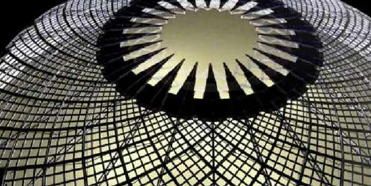
D. Permea has coverd half of the central part of dome.
E. Permea system has reached to 3/4 of central dome, just leaving small opening at the centre.
114
Fig 2.4l: Stage wise opening and closing the roof of dome designed for Abu Dhabi’s international airport.
F. Permea system at the centre of dome is fully opened to cover the central part of dome.
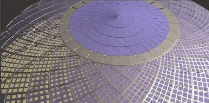
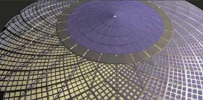
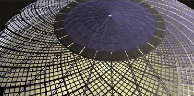
G. After the central part is fully closed the permea at the periphery of the dome starts openeing up ,to cover the whole dome. It starts opening according to the requirement or by sensing dust as well as sand strom. In this case the permea is closing from the right side.
H. Opening of permea in this case has started from the right will end at the left , which will gives beautiful rhythmic character to the user at the bottom of central part inside the dome. Which is Diferently shown in [ Fig 2.4 j].
I. Permea system in a dome is fully opened covering the whole dome and protecting the whole dome from extra light, heat and from sand strom.
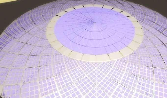
115 Light
Case Study 2.5: Thermo Bimetallic Smart Screen System
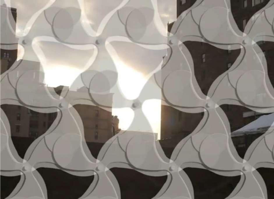
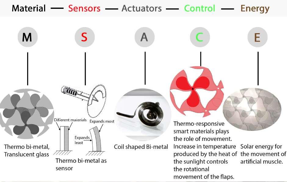
116
Fig 2.5 b: Thermo Bimetallic Smart Screen
Fig 2.5 a: Elements used in smart screen system.
THERMO BI METALLIC SMART SCREEN SYSTEM: A smart system, which senses the environment and uses the thermal as well as light incentives to maintain interior rendering and temperature.
Thermo is related to heat and bimetal refers to an object that is composed of two separate metals joined together. Thus, Bimetallic objects consist of layers of diferent metals. A bimetal bar is usually made of brass and iron. 1
Hence two diferent materials have diferent properties. When bimetallic strip is subjected to temperature change, one layer expands or contracts more than the other, thus tending to change the curvature of the strip[Fig 2.5 c]. This bimetallic strip is an essential element in a thermometer. When used in thermometers, the bimetallic strip is normally wound into a fat spiral [Fig 2.5 d], a single helix, or a multiple helix. The end of the strip that is not fxed in position is fastened to the end of a pointer that moves over a circular scale. Thus increase in temperature converts a temperature change (input) into mechanical displacement (output). 2
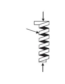
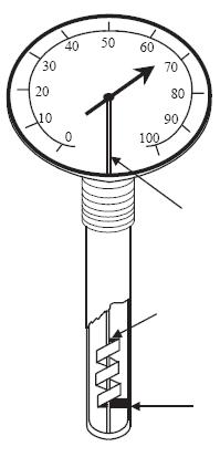
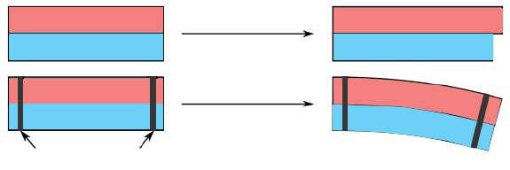
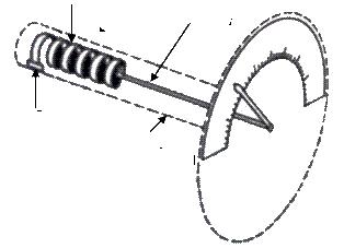
This mechanical displacement is a key design element in smart screen, which is designed by Decker and Yeadon. Smart screen employ intelligent membrane, which reduce energy consumptions by preventing both direct light and the heat of the sun from entering indoor spaces, through the use of autonomous mechanisms that screen without any control by user.
1. http://en.wikipedia.org/wiki/Bimetal.
2. http://frecontrolman.tpub.com/14104/css/14104_236.htm
117 Light
Increase of Temperature Metal 1 Metal 2 Fixed Connection Rotating Shaft Free End Attached to Pointer Shaft Fixed End Free End Fixed End Helical Bi Metallic Element
Bimetallic Helix Spindle attached
Fixed End Scale Outer case of instrument
Fig 2.5 c: Change of displacement in Bimetallic strip due to change
in temperature . A. Main element Fig 2.5 d: Bi Metallic Strip Thermometer B. Themometer C. Working of Thermometer
to end of helix
SmartScreen is a solar shading system that opens and closes in response to changes in ambient room temperature. The system does not require any sensors, processors, motors, or electricity to operate. Instead thermo-responsive smart materials serve as material motors that can open and close the screen by changing their shape. 3 [Fig 2.5a]
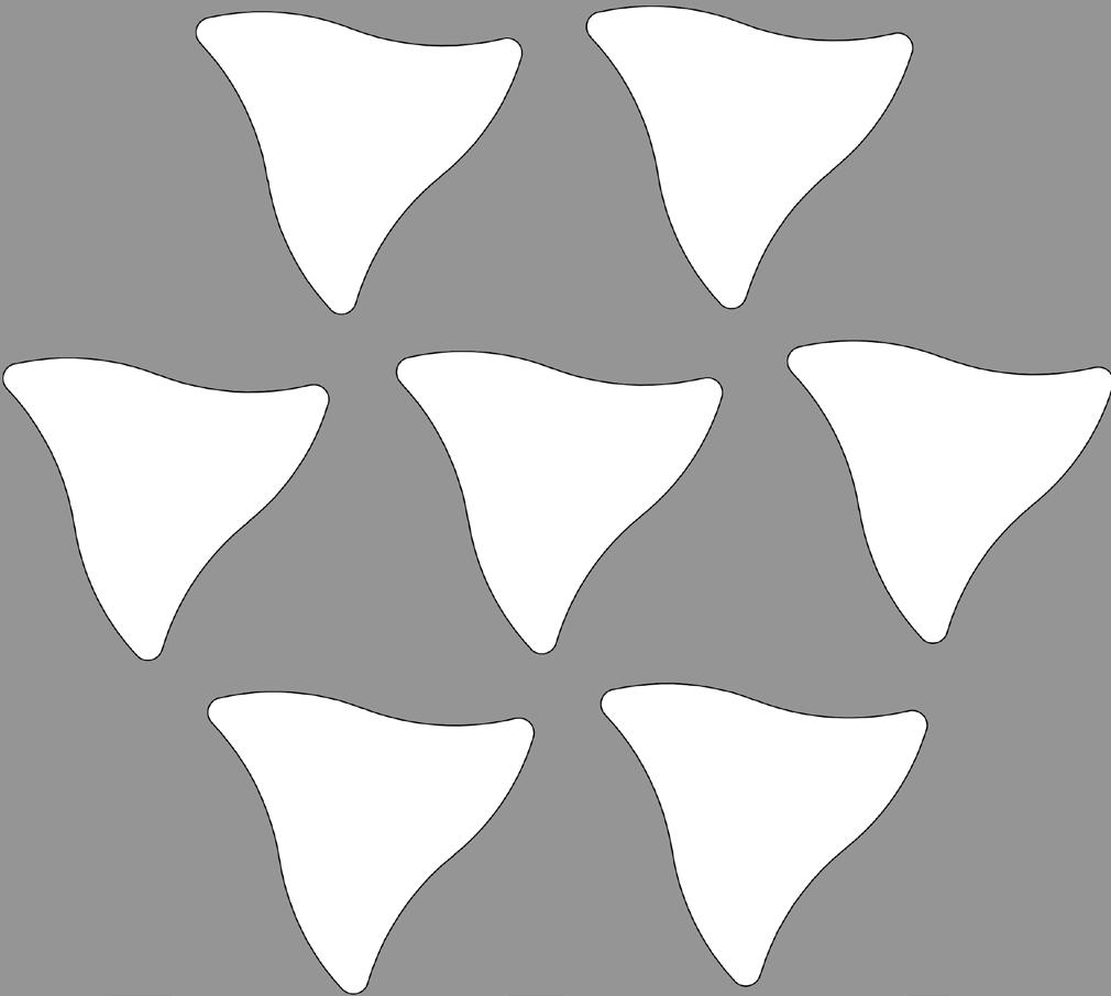
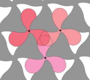
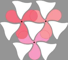
The smart system is conceived to be placed on the east and west facades of a building. The project consists in a mobile mechanism with in a glass enclosure. This smart system consists of two layers one is the fxed pattern. This fxed pattern is negative of the rotating layer and second layer is the one, which rotates. At the initial as there is comfortable environment in interior the rotating layer remain in its original position that is overlapped with the static layer. And when due to excessive heat of the sunlight the mechanism is activated[Fig 2.5 g]. The sun heats up the bimetallic coil - the actuator, which expands and then starts rotating element of the second layer likewise the mechanism in thermometer [Fig 2.5 d], here the end of the coil is connected to rotatable fans, which exactly fts to the openings of the frst layer when the coil expands to its maximum. And hence controls the direct light as well as heat to enter inside the building by closing the opening.[Fig 2.5 e]
And again when temperature and light becomes normal the coil starts cooling up to achieve its initial stage, keeping comfortable environment for the users.[Fig 2.5 f] 3.
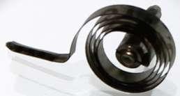
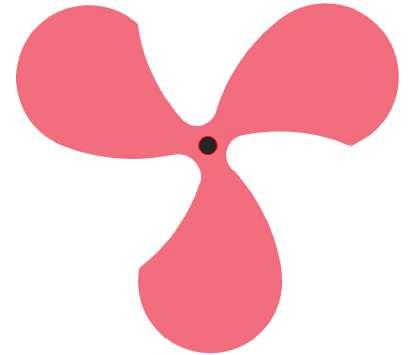
118
http://www.inspirationgreen.com/smartscreen-deckeryeadon.html Page 1 of 2
B.Second Layer -Rotating Fan
C. Bimetallic coil -The Actuator
A. First Layer- Static pattern
Fig 2.5 e: Actuator expands and closes the opening in the frst layer.
Fig 2.5 f: Actuator goes to its normal position and uncovers the openings.
Fig 2.5 g: Thermo Bimetallic smart screen system represented through layering, with actuator.
A. Initial stage : As thr bimetallic coil is at rest and due to ambient room temperature smart screen is at rest .
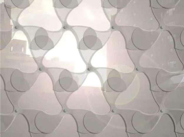
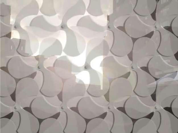
B. Middle stage : Due to increase in outside temperature the actuator actuates the rotating fans to cover the openings in the smart screen to control the inside ambient temperature.
C. End Stage: As bimetallic coil is fully expanded. The fans rotate to its maximum and each opening gets covered by overlapping of the three fns of diferent fans to stop the excessive outside temperature efecting the inside ambient temperature .
And when the outer temperature becomes normal and bimetallic coil cools down the fan goes back to the frst stage.
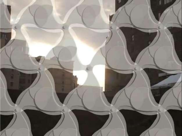
119 Light
Fig 2.5 h:
The human body is a system which works on the same principle of interactive systems which responds to environment and controls the dynamic functioning within, to attain comfortable scenario.
For example an eye, contains Pupil which open and closes thorugh muscles attached with pupil, plays the role of ‘ Material and Sensor’.
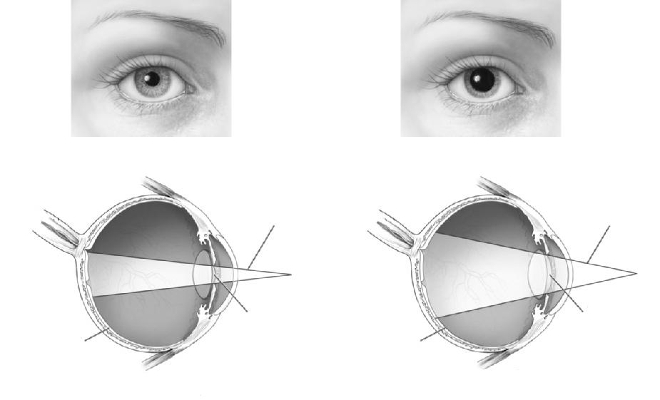
Retina is an actuator which actuates to convert the light into neural signals.
This neural signal through optic nerve gives energy to brain( to start working) for memorising and scanning the information.
Making of expendable coiled strips:
These strips are made of thermo-bimetals (TB), which are made of several metals layers–all welded together with diferent coefcients of thermal expansion. Therefore, when subjected to heat, the metals deform in various and diferent ways, thus acquiring a curving form. The bending is also afected by the ratio of the moduli of elasticity of the metallic layers and their thickness ratio; it is, furthermore, the bending of the metal is directly proportional to the diference in the coefcient of expansion and the temperature change of the component. When it is not subjected to heat, the system resumes its original position.4
In nature some membranes plays these kinds of role like for example in human body, the same system can be seen in human eyes where pupil contracts in presence of higher lighting condition and expands at the lower lighting condition, so that we can see comfortably in both the conditions without damaging our retina.
“With direct exposure to sunlight, the enclosure experience a “miosis” function, or the constriction of light, based on thermal expansion properties of smart material and programmatic structural arrangement. With no direct exposure to sunlight, the enclosure experiences a “mydriasis” or dilation function, allowing for indirect light to penetrate into interior spaces based on the orientation and materials ability or recoil with lack of heat input”.(Vander Werf: 2009)5
4.Screencity Journal Issue # 2 ; Colour, Environment, Interactive Media(10_SCJ2_ gregoris. Pdf ) Pg 2
5. Screencity Journal Issue # 2 ; Colour, Environment, Interactive Media(10_SCJ2_ gregoris. Pdf ) Pg 3
120
Undilated Pupil
Optic Nerve Optic Nerve Light beam Light beam Retina Retina Pupil Pupil
Dilated Pupil
Fig 2.5 i: Interactive system in Human eye.
A. Position of Retina that can be seen through undilated pupil
B. Position of Retina that can be seen through dilated pupil.
At room temperature
“Some more experiments were performed in order to fnd the most suitable material for the membranes, which can perform functions that can be contradictory to each other like day lighting versus energy efciency, ventilation versus views and energy generation. By actuating these interactive systems and making them dynamic, they can better adapt to the conditions, provide for improved comfort of the occupants, and achieve a more suitable design by reducing the compromises needed for that balance.” 6
At temperature 400 C, time 5 sec
Homeostatic kinetic interactive systems are another signifcant example of intelligent and smart adaptive skin by Decker and Yeadon.
At temperature 600 C, time 10 sec
At temperature 800 C, time 20 sec
interior from excessive heat and light .
At room temperature.
- All the four layer are at rest.
- Shell is open.
Each shell connected to bimetallic coil, as temperature increases the open shell start changing to semiopen to closed.
On heating.
- Bimetallic coil starts rotating, due to expansion.
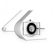
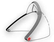
- Shell changes to semi open.
Final output.
- shell encloses and protects itself from heat and light.
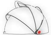
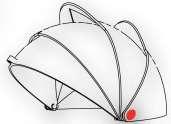
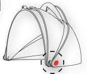
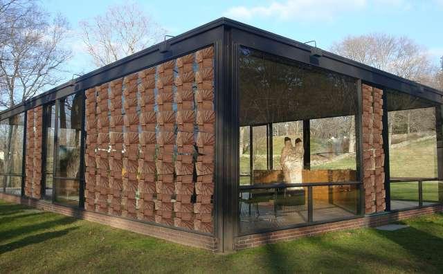
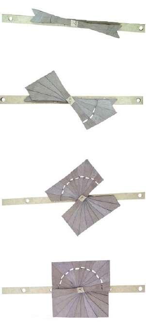
Further heating.
- shell becoming enclosed.
6.Screencity Journal Issue # 2 ; Colour, Environment, Interactive Media(10_SCJ2_ gregoris. Pdf ) Pg 4
121 Light
Fig 2.5 j: Conceptual model and Prototype of a membrane made by bimetallic coil to protect
Fig 2.5 k: Conceptual model of shell which protects its interior from excessive heat and light by changing itself from open to semi open to closed shell.
Case Study 2.6: Homeostatic Smart Screen System
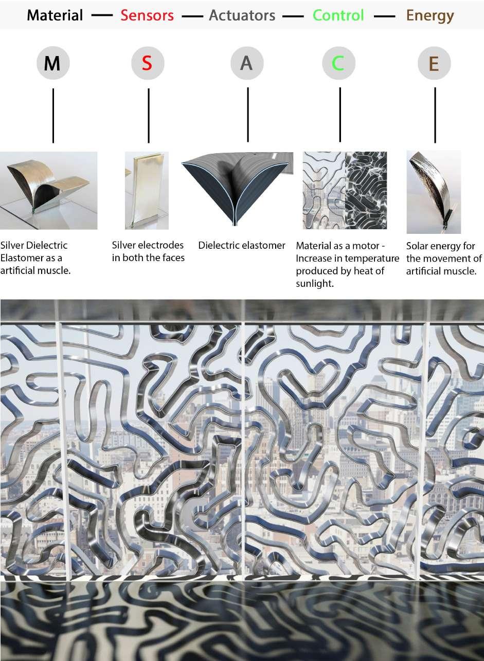
122
Fig 2.6 b: Homeostatic facade regulating indoor temperature by expanding and contracting like muscle.
Fig 2.6 a: Elements used in homeostatic facade system.
Homeostasis is the natural phenomena in plant or animal organisms wherein they constantly regulate their internal conditions through any number of actions. Human sweat is an example of our homeostatic response to a high level of heat gain. Technologies like these bring desingners and architects one step closer to designing buildings that intelligently regulate themselves through difernt kinds of interactivities that organisms do on a systems and processes level.4
HOMEOSTATIC FACADE SYSTEM: A fexing muscle in which a maze like assembly of curvilinear Di-electric (DE) surfaces elongates and contracts, adjusting the degree of solar shading as needed for the building interior. 1
Architectural material technologists frm Decker Yeadon designed a double-skin glass facade system for large buildings that opens and closes itself in response to the internal temperature of the building. This system is called the Homeostatic Facade System, smart materials regulate the building’s climate, just as many organisms maintain their own temperatures through homeostasis.2 [Fig 2.6 b]
This facade efectively regulates temperature throughout a building’s interior. The key is something called a dielectric elastomer that uses electricity to change shape. The electricity deforms the silvery squiggles, expanding them when it’s hot. [Fig 2.6 a]
The facade can respond along individual segments to small-scale variations in local environmental conditions. The swirling ribbons of the facade are composed of an elastomer (a rubber-like polymer) wrapped over a fexible polymer core. A silver coating on the elastomer distributes an electrical charge across its surface, causing it to deform much as electrical signals initiate muscle contraction [Fig 2.6 c]. When sunlight warms up the building at certain times of day, the surfaces of the ribbon expand to create shade inside the building. When temperatures drop, they contract to allow more light in. In nature, this sort of self- regulation is known as homeostasis.3
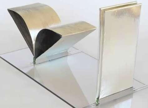
1.http://www.architectmagazine.com/blogs/postdetails.aspx?BlogId=mindmatterblog&postId=100172.
2.http://www.internationalfacade.com/news/general/homeostatic-building-facade/#.VFV5Zr7ClSV Page 1 of 3.
3.http://www.internationalfacade.com/news/general/homeostatic-building-facade/#.VFV5Zr7ClSV Page 2 of 3
4.http://www.biomimetic-architecture.com/2011/decker-yeadons-homeostatic-facade-system/ Page 2 of 4.
123 Light
Fig 2.6c: Prototype of dielectrical elastomer A. When elastomer is fully expanded. B. Elastomer is at rest.
A B
Electrode 1 Electrode 2
Contemporary double skin facade systems for the large buildings have both an exterior glass curtain wall and an interior glass surface that are separated by air cavity. The air cavity consists of shading mechanisms that enables the systems to automatically regulate the heat loss and gain. The design for homeostatic facade system advances double skin technologies by taking advantage of the unique fexibility, in low power consumption of dielectric elastomers. The hidden designs opens and closes to control solar heat gain through the facade, automatically responding to the environment conditions [Fig 2.6 d]. This highly deviation is achieved through a simple and elegant actuation seen here in section [Fig 2.6 e,i]. The actuators are the artifcial muscle consisting of the dielectrical elastomer wrapped over a
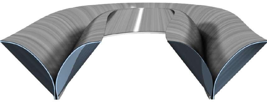

124
Fig 2.6 e: Section of actuator with dielectric elastomer wrapped over a silver coated core.
Fig 2.6 d: At normal temperature dielectric elastomer is fully closed connecting inside with outside. But increase in outside temperature opens the elastomer and regulates inside temperature of building.
Dielectric elastomer Electrode
Silver coated wrap
Electrode
fexible power core. Expansion and contraction of the elastomer causes the fexible core to bend. Now where the top of the power core insures smooth motion as the lastomer moves, the dielectrical elastomer includes the silver electrodes in both the faces. The silver assists the system by refecting and difusing the light, while distributing an electrical charge across the elastomer causing it to deform, as seen in this stimulation [Fig 2.6 h].
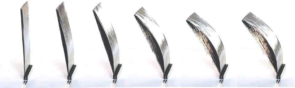
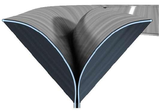
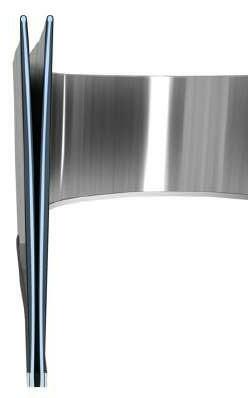
Inspired by the homeostasis in biological systems the facade regulates the buildings climate by automatically responding to the environmental conditions. Its advantage of a conventional system lies in its low power consumption in superior precision, because the surface of the material is also the motor, it essentially ofers localized control over any segment of the facade. This way of control can only benefts the contemporary architecture, which has become increasingly more transparent [Fig 2.6 f,g]. It provides the thermal regulation while reducing energy consumption in its associated divisions.5
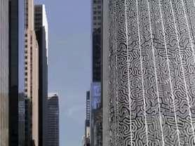
Electrode
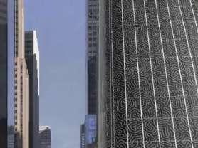
125 Light
Dielectric elastomer
2
1
Fig 2.6 f: Building facade gets fully covered due to excessive heat.
Fig 2.6 g: Building facade connects inside with outside at normal temperature.
Fig 2.6 h: Stimulation in dielectric elastomer prototype, closed at normal temperature and as temperature increases it open to bend and buldges to its maximum.
Fig 2.6 i: Opening and closing of dielectric elastomer wrapped in a sliver coated sheet.
https://www.youtube.com/watch?v=GEipnLf40_Y
A. Section of actuator when its fully opened (actuated) B. Section of actuator when at rest, fully closed.
5.
Elastomeric flm (dielectrica)
Coating (electrodes)
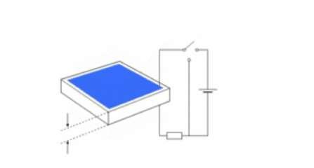

Stage 1
Application of the electrodes
Stage 2
Application of the electrodes
Stage 3
Stage 4
Application of the electrodes
Connection to an electrical circuit
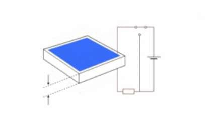
Stage 5
The actuator is activated
Stage 6
Application of a voltage U
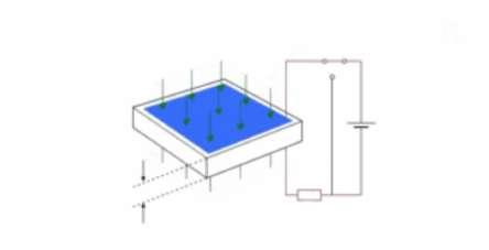
Stage 8
The actuator elongates
The actuator elongates
Stage 7
Stage 9
Elastomers are amorphorous polymers, at ambient temperature are relatively soft and deforms like rubber. Increase in temperature through current fow, increases there softness and hence elastomers elongates.
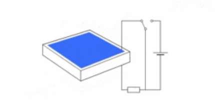
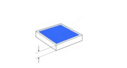


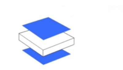
At the same time due to no current fow temperature becomes normal and elastomers goes back to their original state.
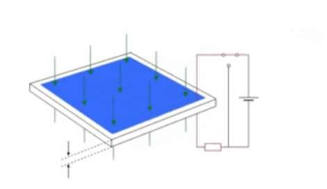
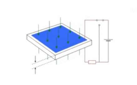
Stage 10
Stage 11
126
Short-circuit U U R Z Z Z Z Z Z U U U U R R R R R P el P el P el
Fig 2.6 j: Basic stimulation of dielectric elastomer with electrodes .
Increase in Heat (Temperature)
A dielectric elastomer is composed of elastomeric flm that when exposed to a current expands [Fig 2.6 j] . In the case of Decker Yeardon’s product ‘The homeostatic facade’, the elastomers are connected to a fexible polymer core. Silver electrodes cover the elastomer. This distributes the current and acts as a refector in the system as the bands bend away from each other like the wings of a butter fy [Fig 2.6 i,k]. 6
When this system is installed in a double glazed system it reacts to the conditions passively and automatically to regulate solar gain. It also creates a dynamic system that changes throughout the day in response to solar conditions [Fig 2.6 l]. 7
Today much of contemporary building designs employ glazed facades. These double-skin glass walls, while creating transparency, pose a problem with solar gain.
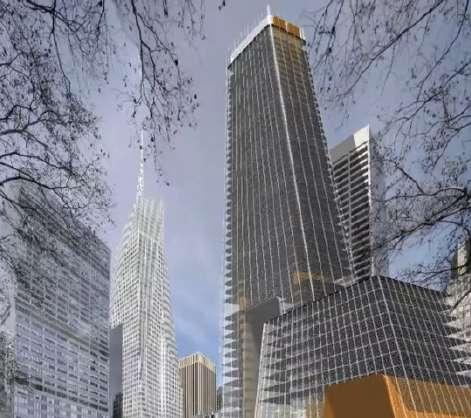
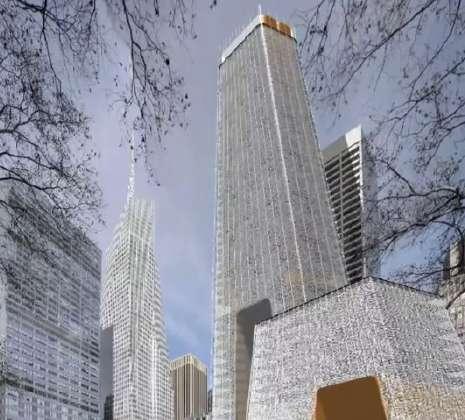
Increases current fow
Elastomer shows actuation ( Elastomer elongates)
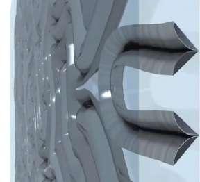
Homeostatic facades have the potential to improve environmental conditions in interior of commercial, glazed buildings and will lead to a reduction in energy needs. As glazed facades don’t seem to be disappearing, but ever increasing, more systems of this sort will be surely seen.
6. http://arch5541.wordpress.com/2012/11/08/2534/Page 1 of 4.
7. http://arch5541.wordpress.com/2012/11/08/2534/Page 3 of 4
127 Light
Fig 2.6 k : Elastomer fully elongated due to excessive heat.
Fig 2.6 l : Homeostatic facade changing the contemporary glass buildings outlook from transparent to opaque.
A. The contemporary glass building covered by homeostatic facade system protects buildings interiors normal temperature from the excessive heat outside.
B. The contemporary glass building covered by homeostatic facade system allowing the connectivity from inside to outside by sensing the normal temperature outside.
Case Study 2.7: Triangular shades
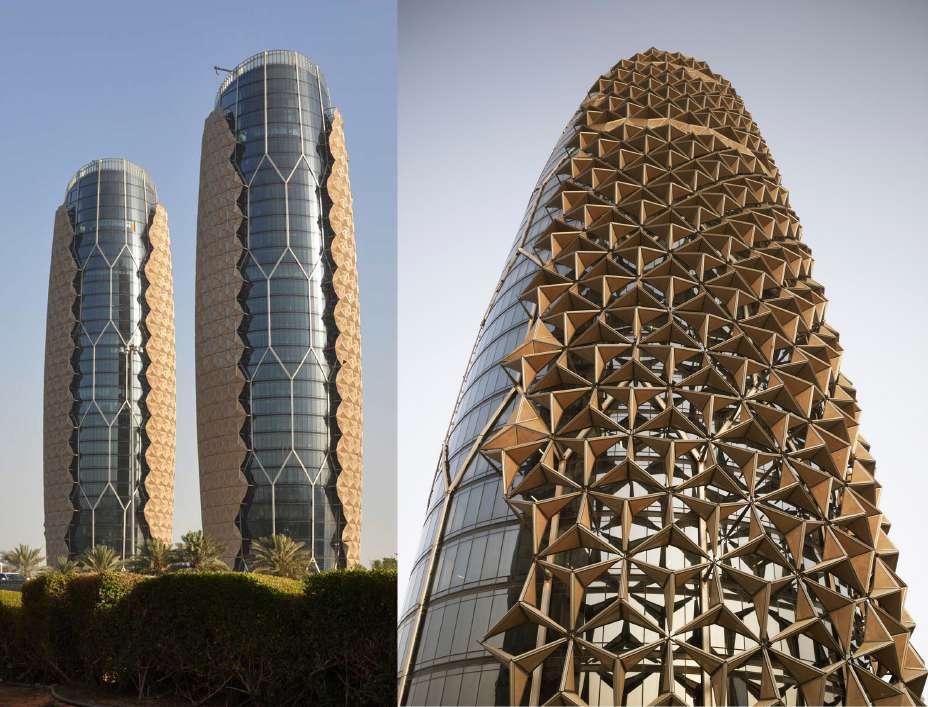
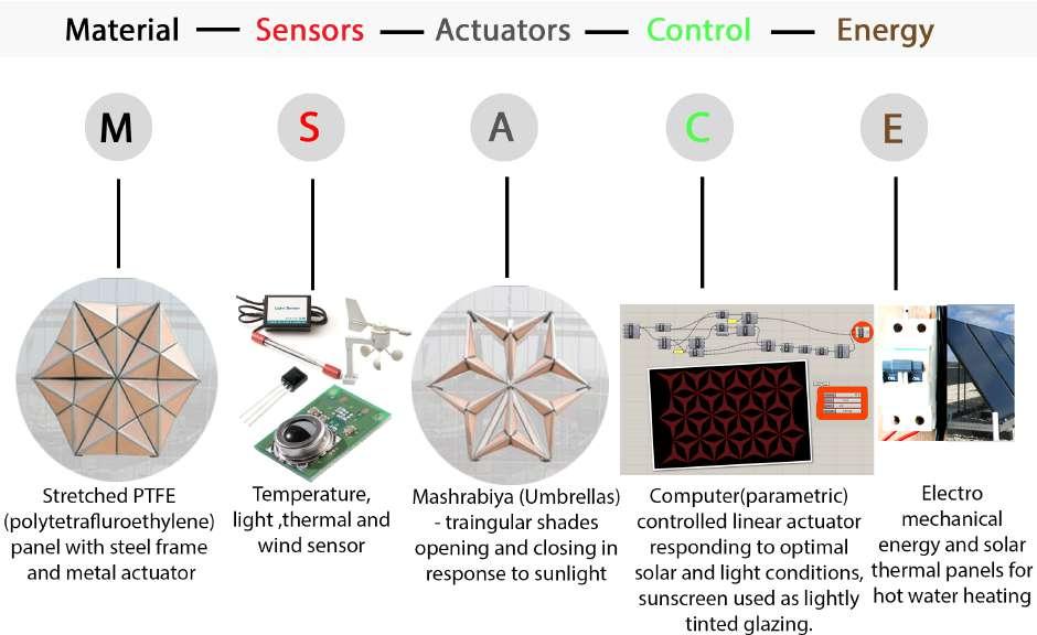
128
Fig 2.7 a : Elements used in dynamic- intelligent- traingular shades.
Fig 2.7 b: Intelligent units controlling the outer glass facade from direct heat of sunlight.
TRIANGULAR SHADES: Abu Dhabi’s Al Bahar towers have incorporated ‘dynamic facade’ an external automated shading system known as intelligent umbrellas, which has been inspired by the cultural clues from the ‘mashrabiya’.
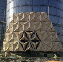
Mashrabiya is a popular form of wooden lattice screen found in vernacular Islamic architecture and used as a device for achieving privacy while reducing glare and solar gain.
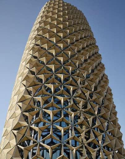
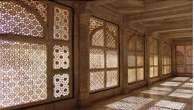
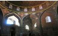
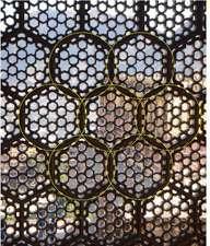
[ Fig 2.7 c,d]
The project brief called for two, 25-story towers to create an outstanding landmark that would refect the region’s architectural heritage together with the status of the client’s organization while providing a contemporary building using modern technology such as ‘interactive systems’, taking care of most important environmental factor which is desert sun and sand storm.1 [Fig 2.7 a,b]
The “Mashrabiya” at Al Bahar Towers comprises a series of transparent umbrella-like components that open and close in response to the sun’s path. Each of the two towers comprises over 1,000 individual shading devices that are controlled via the Building Management System, creating an intelligent facade.2 [Fig 2.7 b,e]
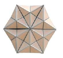
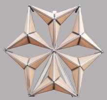
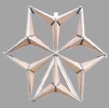
Each unit comprises a series of stretched PTFE (polytetrafuoroethylene) panels and is driven by a linear actuator that will progressively open and close once per day in response to a pre-programmed sequence that has been calculated to prevent direct sunlight from striking the facade
1. 2012AwardsBook_AlBahar.pdf- page 172
2. 2012AwardsBook_AlBahar.pdf- page 174
129 Light
Fig 2.7 c: Mashrabiya, a traditional islamic architectural element ,based on geometrical patterns inspired from nature.
Fig 2.7d: Mashrabiya reducing direct glare but able to render sufcient light in interior.
Semi Open
Fully Open
Fully Closed
Fig 2.7 e: Shading units transforms fully open to fully close by sensing the movement of sun.
and to limit direct solar gain to a maximum of 400 watts per linear meter. The entire installation is protected by a variety of sensors that will open the units in the event of overcast conditions or high winds. The efects of this system are comprehensive: reduced glare, improved daylight penetration, less dependent on artifcial lighting, and over 50% reduction in solar gain which results in a reduction of CO2 emissions by 1,750 tones per year.3
Mashrabiya, sensitive shading screen system is powered by renewable energy derived from photovoltaic panels. Thesewraps the giant lattice almost two towers completely except for the area north-facing facades.
The screen operates as a curtain wall, sitting two meters outside the buildings’ exterior on an independent frame. Each triangle is coated with fberglass and programmed to respond to the movement of the sun as a way to reduce solar gain and glare in the interior of the building, making it comfortable for the users.[Fig 2.7 g,h,i]
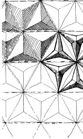
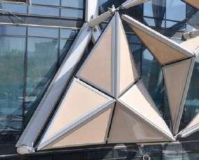
“At night they will all fold, so they will all close, so you’ll see more of the facade. As the sun rises in the morning in the east, the mashrabiya along the east of the building will all begin to close and as the sun moves round the building, then that whole vertical strip of mashrabiya will move with the sun,” said Peter Oborn, the deputy chairman of Aedas.4
[Fig 2.7 l]
Main Components:
1. Actuator + Power & Control: cable connection back to the tower.
2. Strut Sleeves: penetrates the curtain wall & connects to the main structure.
3. Supporting cantilever Struts: hooks on the sleeves.
4. Star Pin Connection: receives the unitized Y-Arm ends.
5. Actuator Casing: protects the actuator.
6. Y-Structure Ring Hub: joins the Y-Arms and actuator together .
7. Y-Structure Sleeves: connects the Y-Arms to the Hub.
8. Y-Structure Arms: supports the whole mechanism.
9. Y-Mobile Tripod: drives and supports the fabric mesh frames.
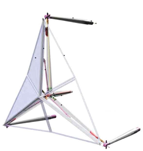
10. Actuator Head Pin Connection: pins to the Mobile Tripod.
11. Stabilizer: takes the loads to the hub releasing the actuator shear forces.
12. Slider: allows the Mobile Tripod to travel along the Y-Arms.
13. Fabric Mesh Frame & Sub-Frame: supporting the fabric mesh.
14. Metal Frame for fabric mesh.
15. Fabric Mesh (PTFE).
3. http://www.ctbuh.org/TallBuildings/FeaturedTallBuildings/AlBaharTowersAbuDhabi/tabid/3845/ language/en-US/Default.aspx Page 2 of 5.
4. Al Bahar Towers Responsive Facade / Aedas | ArchDaily.pdf, page 2 of 4.
130
4 3 2 1 13 10 14 15 12 11 6 1 & 5 7 8 9
Fig 2.7 f: Initial sketch of design.
Fig 2.7 g: Detail view of single unit .
Fig 2.7 h: Detail diagram of single unit in a shading screen.
The end result is a dynamic outer screen that is programmed to respond to the sun’s movement, shielding the building’s eastern side in the morning and moving round westwards with the sun throughout the day.5 [Fig 2.7 k]
The overall form of the towers was optimized to complement the shading system. The design began with two simple cylinders, the circular plan giving the most efcient shape in terms of wall-to-foor area while also creating the greatest volume with the least surface area. The circular plan form was then articulated based on a combination of circular geometries to reduce solar exposure, and began to generate a natural orientation. The form of the towers was then sculpted around the core, narrower at the base and at the top, but broader around the intermediate foors. The building also incorporates the use of solar thermal panels for hot water heating. [Fig 2.7j]

Al Bahr Towers in Abu Dhabi is the frst large-scale commercial project in the world to feature a dynamic, intelligent facade that cools or insulates the building from direct response to the sun’s movement.6 [Fig 2.7m]
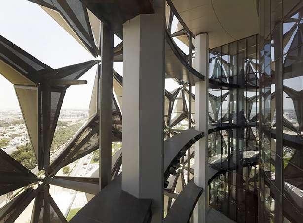
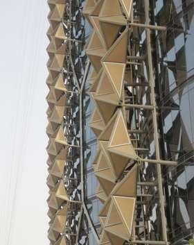
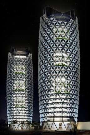
5. http://www.e-architect.co.uk/dubai/al-bahar-towers-abu-dhabi Page 3 of 12
6. http://www.e-architect.co.uk/dubai/al-bahar-towers-abu-dhabi Page 1 of 12
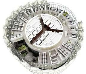
131 Light
Fig 2.7 i: Dynamic screen attached to the exterior of the building.
Fig 2.7 j: Plan of Albhar tower.
Fig 2.7 k: Comparison of shading units fully open to fully closed by tracking the movement of the sun
Fig 2.7 l: All units fold at night, so that building glows.
Fig 2.7 m: Shading pannel viewed from the interior, protecting the interior form the heat and light of the sun.
Case Study 2.8: Glass Disc Shades
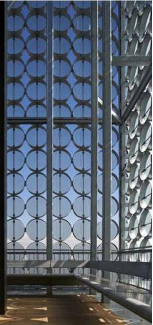
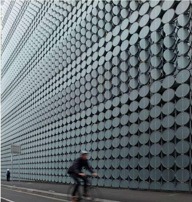
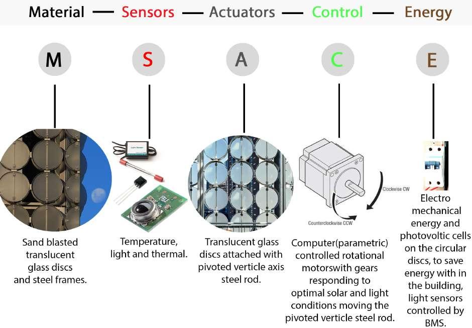
132
Fig 2.8 b: A.West facade of RMIT, all the nine disks from bottom are fxed. B. Covered terrace,RMIT
Fig 2.8 a: Elements used in Dynamic Glass disc facade.
“In the most straightforward sense, a building with sensors, controllers for adjustable blinds, and dimmable lighting all tied together is a dynamic system,” says Mic Patterson.2
GLASS DISK FACADE : A double-skin facade with a unique external skin that incorporates glazing disks. The smart disk will track the sun with sensors using computer automation to shade the building interior.1
The Design hub facade at RMIT University ofers shading that is critical to the interior environment quality and delivery of energy efciency of the building. The design hub is set to be a vibrant center of post graduate design research and education. [Fig 2.8c]
The outer layer of the double-skin facade for the Design Hub at the Royal Melbourne Institute of Technology (RMIT) consists of more than 16,000 individually mounted translucent glass discs repeated on all four elevations of the nine-story main building. Some of the cellular units has groupings of the discs which automatically pivot around a vertical axis in response to the sun’s position. While some of the units are static.3[Fig 2.8 b,d]
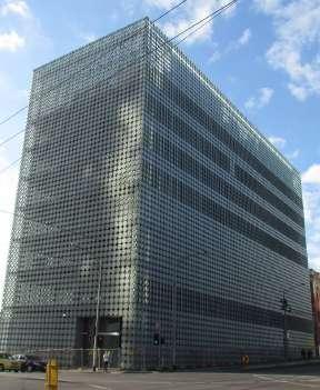
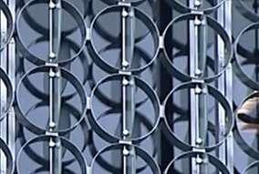
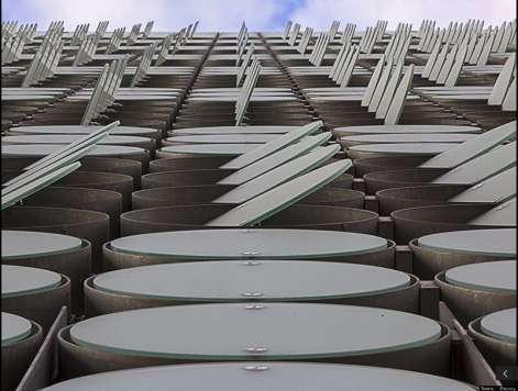
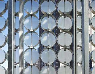
Sensors such as temperature ,light and thermal, with the controllers and actuators, change the disk movement according to the sun’s position. [Fig 2.8a]
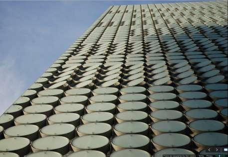
133 Light
1. http://www.rmit.edu.au/capitalworks/designhub Design Hub - RMIT University.pdf 2. Dynamic Facades/ Buildings Show O f New Moves | | | techfeatures | Architectural Record.pdf,pg1 3. Dynamic Facades/ Buildings Show O f New Moves | | | techfeatures | Architectural Record.pdf,pg1
Fig 2.8 c : Glass disc facade protecting RMIT interiors from direct sunlight. A.
Low
emmisivity flm disc, fully opened.
B.
Discs opened to 5 degree. C. Discs fully closed
Fig 2.8 d: Each panel in diferent area senses diferently.
Designed by Australian Architect Sean Godsell. A nine storey tower’s outer facade is covered by 774 panels, each with 21 pieces of sandblasted glass discs, 600mm in dia and 3/8 inch thick. The disks are attached into 130mm - deep galvanized steel cylinder, where disks are fxed, either on a horizontal or vertical steel axel. Each axel is fxed to the outer face of steel cylinder. The panels sit in a steel frame separated by about 3 feet from the building’s inner facade.4 [Fig 2.8 e,f,]
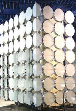

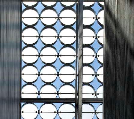
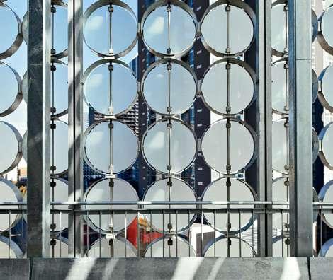
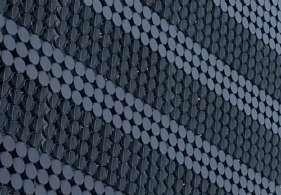
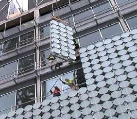
As a system disks are pre-assembled into 1.8x4.2m panels. Where, out of 21 discs, 12 are operable and nine are fxed, apart from those on the ground foor and plant-room levels, which are all fxed. The operable discs open to 90 degrees , pivoting on horizontal axles on the north and south elevation . And the vertical axel on the east and west elevations, giving the facade an orientation specifc response.5 [Fig
g,h,l]
130mm deep galvanised steel cylinder.
600mm sandblasted circular disk.
http://www.architectural-review.com/essays/rmit-design-hub-by-sean-godsell-architects-melbourne-aus-
134
2.8
Steel axel.
7 6 5 4 3 2 1
4. RMIT Design Hub / Sean Godsell | ArchDaily.pdf,page2
5.
tralia/5218171.article
Fig 2.8 e: Panels assembly getting fxed to the facade.
Fig 2.8 f: Out of seven rows last three rows fxed with static discs and frst four are pivoted.
Fig 2.8 g: Vertical axel pivot on East and West facade.
Fig 2.8h: Horizontal axel pivot on North and South facade.
Over the course of an hour, the discs open as little as 5 degrees up to a maximum angle of 90 degrees. However, their movement is actuated by electrically operated Actuators and each panel is controlled by the Building Management System (BMS). BMS is programmed to close to
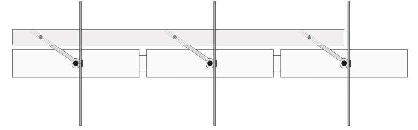
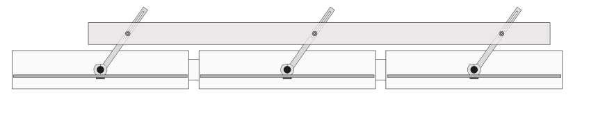
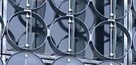

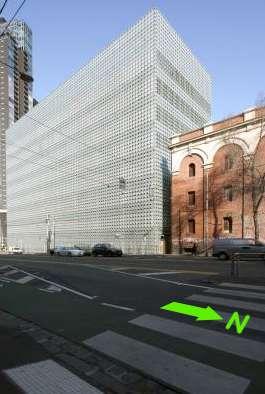
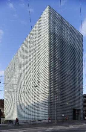
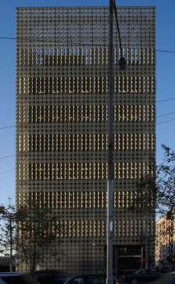
135 Light
Fig 2.8i: RMIT building at night.
Fig 2.8 j: Mechanism of discs when opened.
Fig 2.8 k: Plan of single panel .
Fig 2.8 l: A. West and South Elevation, B. South (Front) Elevation, C. East and North Elevation, RMIT building, Melbourne, Australia.
A. Mechanism of discs at maximum 90 degree, opened.
B. Mechanism of discs at closed condition.
Manifestation of Interactive System as an Element in the Interior Spaces :
INTERIOR EXTERIOR FACADE
INFERENCE :
This chapter gives an overview on how the interactive systems in interior of the building or on the facade - outside the building maintain the light quality as well as temperature in the interior of the building. Hence making interior more users friendly. (to more dynamic from mundane static interior).
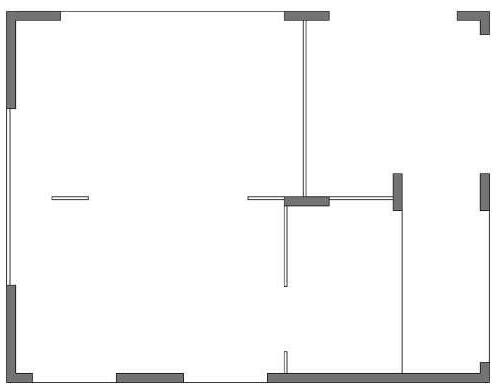
The adaptive fritting and tessellate are such examples of an interactive system in the interior spaces which can transform the opaque ‘personal’ space too transparent ‘open’ space, through sensing the light and the movement of the user in the space. This Interaction results due to involvement of material, sensors, actuators, controls and energy, which together creates am interactive system. The adaptive fritting generally installed in the interior spaces. Where as the tessellate interactive system can be placed at interior wall of the facade as well as in the interior spaces.
The Permea and Strata are such examples that protect the interior light quality as well as temperature from the external non user-friendly light and temperature. Permes can be fxed to the interior as well as exterior wall of the building facade to control the direct glare of sunlight and excessive heat inside the interior spaces.
STRATA on ceiling
136
S E W N
TESSELLATE BIMETALLIC PERMEA HOMOSTASIS FRITTING F H P B T S
Fig 3.13: Reference diagram to place the interactive elements in actual space.
Interactive systems can be designed for the interior spaces according to the need like through interaction controling light inside the spaces, light inside the building, maintaining thermal heat inside the space, controlling air pressure etc, so that the interior as well as the building becomes more user friendy.
The diagram at the right and left represends the manifestation of the interactive element according to the need inside the building , like;
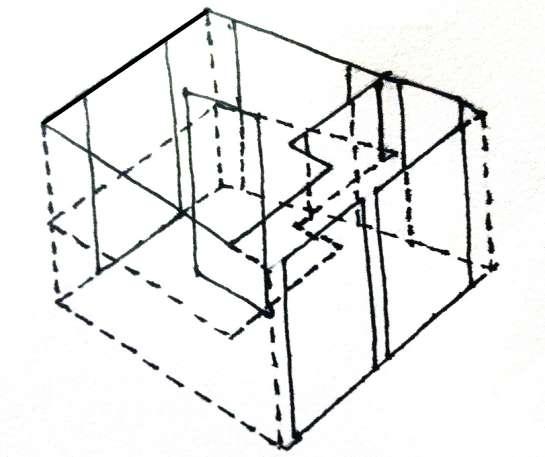
FRITTING IN A PARTITON ELEMENT IN INTERIOR - To get upgraded about the meeting space.
HOMOSTASIS AT THE EAST FACADE- To control the glare of sunlight inside the building.
PERMEA AT SOUTH FACADE - To control the excessive outer heat.
BIMETALLIC AT THE SOUTH AND WEST FACADE - To control the heat and glare coming inside the double height space.
TESSELATE AT THE WEST FACADE
-To give west facade an attractive surface from inside as well as from outside and controlling the glare of sun also.
STRATA ON THE SOUTH WEST OTS
- To control the wind and dust coming inside the building.
In all the four interactive system: Adaptive fritting, Tessellate, Permea and Strata, the energy has to be out sourced to operate sensors, actuators, and controllers. But in the case of smart material such as Thermo Bimetallic and Homeostatic systems the energy is produced with in the system so, such type of systems are energy efcient systems.
Further Triangular shades and the Glass disc are such interactive systems, which controls and protects the quality of interior such as light rendering and temperature with BMS (Building Managem System) from the outside fuctuating environment, like change in air fow, light quality etc. These systems help building in maintaining their interior environment from exterior and controls the excessive use of artifcial energy such as air conditioning and light sources in the interior of the space.
Triangular shades and glass disk are such examples of interactive systems, which can be incorporated to the already made glass facade building, most of which are less user friendly. By using such interactive system can make those building more users friendly.
Such interaction can also help the transparent interiors and architecture to become more energy efcient.
Now in next chapter we will see how these interactive systems further controls the micro and macro climatic conditions in the interior of the building with respect to the external natural climate, which is ever changing and sometimes not user friendly.
137 Light
Fig 3.14: Reference diagram.
138
CHAPTER - 3 MICRO CLIMATE


139 Microclimate
USER LIGHT MICROCLIMATE BRANDING
MICRO CLIMATE:
The climate of the earth consists of a series of interlinked physical systems powered by the sun.
Climate can be defned as a region with a certain conditions of temperature, dryness, wind, and light etc. climate has four major elements:
1. Earth - Soil
2. Water - Humidity
3. Fire - Sun/Temperature
4. Air- Wind.
In the built environment we are generally concerned with local climatic systems in particular:
Macro Climate: The climate of a larger area such as a region or a country. [Fig 3.1]
Micro Climate: The variation in localized climate around a building. [Fig 3.1]
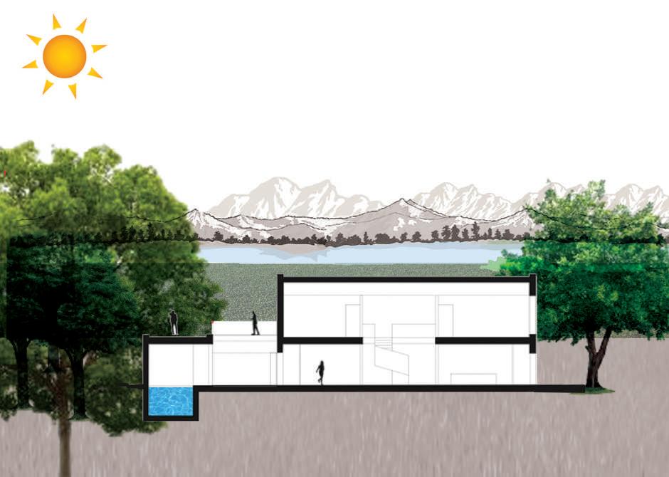
MACRO CLIM AT E CONDITION MICRO CLIMATE CONDITION
140
Fig 3.1: Schematic diagram depicting the zones of macro and micro condtions around a building.
Microclimate
CHANGE IN MACRO CLIMATE
CHANGES IN MICRO CLIMATE
CHANGES IN BUILDINGS ENVIRONMENT INTERACTIVE SYSTEM STARTS ACTUATION
The macro and microclimate has a very important efect on both the energy performance and environmental performance of buildings, both in the winter season and in summer. The site and design of a building can have a profound efect upon the interaction between a building and its environment. Interactive systems in building helps building to be more responsive as well as more receptive, interacting with the active exterior as well as interior environment to control the micro climatic conditions in the interior of the building. Through sensors, actuators, logic controllers and materials, which are the key parts of an interactive system.
To control microclimate, the interactive system can be programmed through the knowledge of the macroclimate in which building is located. Which generally take care data about :
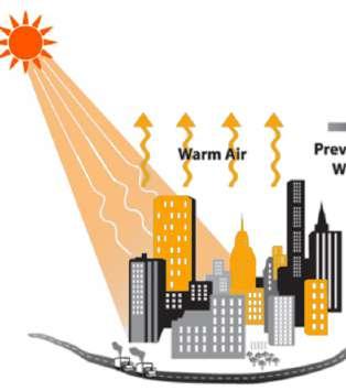
CONTROLLED USER FRIENDLY INTERIOR CLIMATE
moisture contained in exposed surfaces and will efect thermal conductivity of external surfaces.
This Meteorological data gives a general impression of the climate at the site of a building. However the building itself and surrounding geography will afect the local climate.
presence of hills valleys, slopes, streams and other buildings. Surrounding slopes have important efects on air movement around the building. Building themselves create further microclimates by shading the ground, changing wind fow patterns.
One example on how building afects the local climate is the heat island efect in large cities where average temperature is higher than the surrounding area: [Fig 3.2]
Solar energy absorbed and re-emitted from the building surfaces, pavements road etc. creates a warming efect on the surrounding air. Also the large quantities of buildings break up the wind fow, reducing wind speeds and causing the warm air to remain stagnant in the city. This also causes increased pollution as well as temperatures.
141
Fig 3.2: Schematic diagram depicting the Heat Island Efect.
The presence of local high rise buildings can degrade the local climate as wind speed at ground level can be signifcantly increased, while extensive shadows block access to sunlight for long periods, increased space heating coasts in surrounding building.1
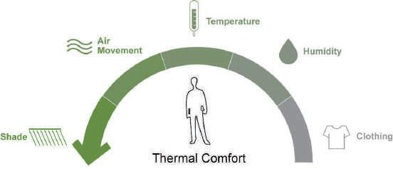
Such scenarios can be healed or improved by installing interactive system in the interiors and out side of the buildings, which will take care of micro climatic conditions controlled inside the building through sensing the surrounding.The microclimate control of building depends on the overall efect of passive solar building design, day lighting as well as orientation of the building and positioning of windows, control on ventilation and humidity, in the interior space of the building.
Passive Solar Building Design: Passive solar design refers to the use of the sun’s energy for the heating and cooling of living spaces. In this approach, the building itself or some element of it takes advantages of natural energy characteristics in materials and air created by exposure to the sun. Hence passive solar design in buildings aims to maintain interior thermal comfort throughout the sun’s daily and annual cycles whilst reducing the requirement for active heating and cooling systems. 2 [Fig 3.3,3.4]
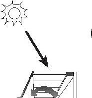
Day lighting: Day lighting is the practice of placing windows or other transparent media, and refective surfaces so that, during the day, natural light provides efective internal illumination.
Orientation of building: The orientation of the large face of the building towards north-south direction is considered to be the best as it avoids the deeply penetrating rays of east and west. Also avoids heating up of the larger side at evening time maintaining temperature balance.
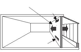
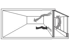
1. http://www.boeingconsult.com/tafe/bcg5013/MacroMicroClimate.htm.

2. http://www.residentialshippingcontainerprimer.com/Passive%20Solar%20Design.
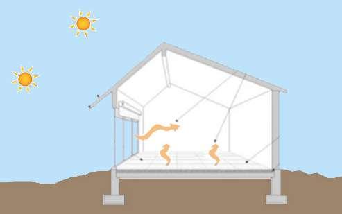
142
Summer Sun Winter Sun Control Aperture Distribution Absorber Thermal Mass
3.3:
Fig
Passive Solar Building Design
Fig 3.4: Five elements of Passive Solar Design
Closed Vent Closed Vent Thermal Mass Wall Night Day
Fig 3.5: User Thermal Comfort Diagram
Microclimate
Windows: Windows are the most common way to admit daylight into a space. Their vertical orientation means that they selectively admit sunlight and difuse daylight at diferent time of the day and year.
Ventilation: Ventilation is the movement of air within a building and between the building and the outdoors. Control of ventilation is most subtle yet important concerns in building design.
Humidity and Building Design: Moisture can be a liability if it comes in the form of humidity; causing such sickness that summer. Strategies to reduce the discomfort of high humidity: Maximizing ventilation, inducing air fow around facilities.
In previous chapters the perception and experience of user in space changes as interactive system interacts with users and light in the interior of a building, giving a user-friendly environment to the building.
Now in this chapter we will further discuss how these Interactive systems can control the micro climate of the room in the personal space, to diferent functional spaces in the home, to the micro climate control in the public spaces like stadiums, through the act of sensing, actuating, material properties and logic controllers.
A Study of Interactive safe house in Poland and University ofderstand about how these interactive systems controls micro climatic in the interior of the personal space like house, to the public space like stadium.[fg 3.6,3.7]
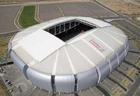
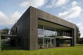
143
MICRO CLIMATE Day Lighting System Apertures Shading Devices Day Lighting Devices Interior Element Interior Surface Characteristics Built Form and Orientation
Fig 3.8: Diagram showing the aspects of building efecting Micro Climate around and inside the building.
Fig 3.6: Safe House , Poland
Fig 3.7: Phoenix Stadium, Arizona
Case Study 3.1: Micro Climate - Interactive Safe House
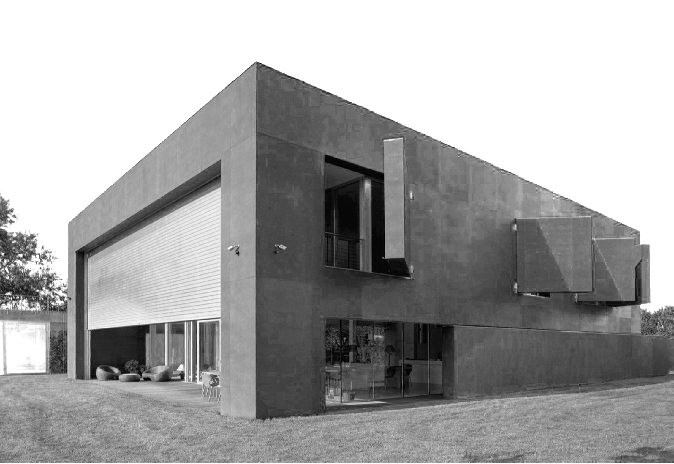
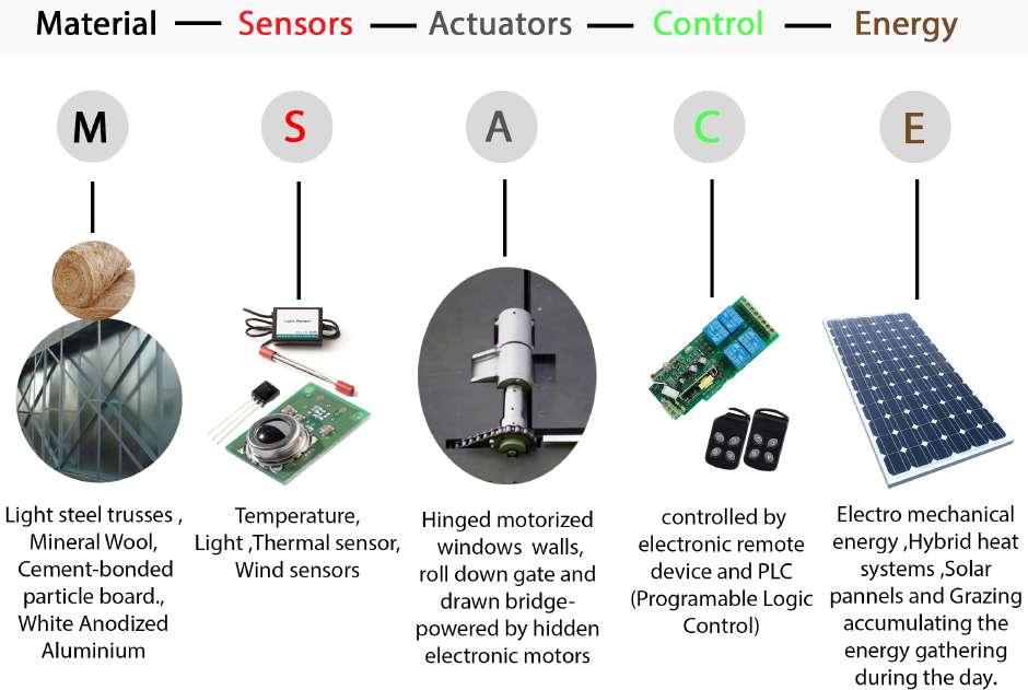
144
Fig 3.1b: Movable elements controlled by interactive system in safe house.
Fig 3.1a: Elements used in interactive system.
INTERACTIVE SAFE HOUSE: A building that opens as sun rises and closes as sun sets interacting with nature becoming more energy efcient.
An Interactive Safe House designed by architect Robert Konieczny, is situated near Warsaw, Poland. This spectacular 6100 sqft home is transformed with an interactive system such as movable large windows and walls. Such interactive elements help built form to become energy efcient as well as controlling of microclimate around and within the house. And further also achieves strength for the privacy and the security. The architectural frm KWK Promes has designed this building which transforms at the act of sensing, actuation and control.1 [Fig 3.1a,b,c,d,e]
1. http://www.mildred.co/issue-64/my-place-or-yours/the-safe-house/.
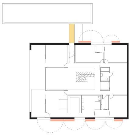
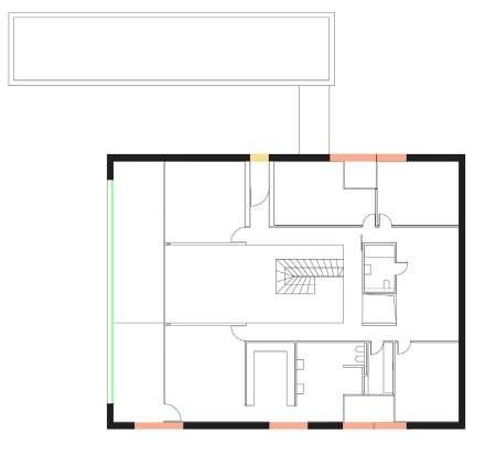
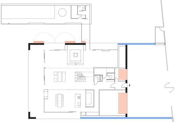
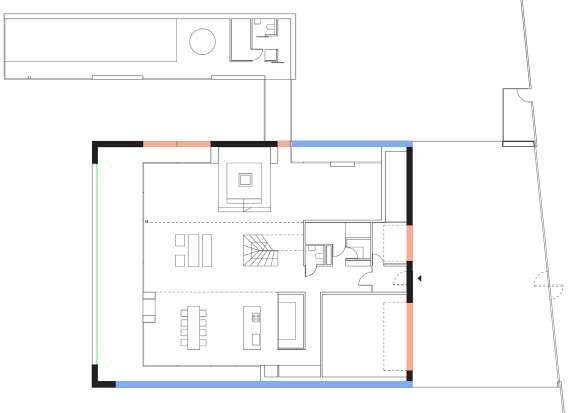
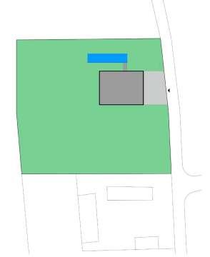
145
Microclimate
Fig 3.1c : Site Plan
Fig 3.1e : First Floor Plan.
B. When House is Open
B. When House is Open
A. When House is closed.
A. When House is closed.
N
Interactive Window Interactive Walls Convertible Bridge
Tis interactive house consists of 22 meters long and 2.2 meters high longest movable walls of the building on the ground foor, which moves through sense of light as well as can also be controlled through electronic remote by user. And on the frst foor there are 2.8 Meters high and 3.5 Meters wide shutters opens up to 180 degrees, which plays the role of windows.2 [Fig 3.1f,g,h,i]
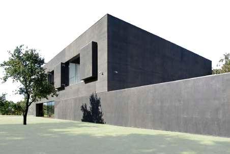
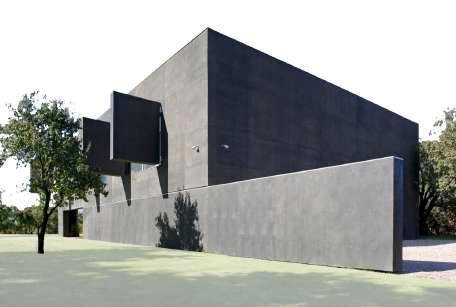
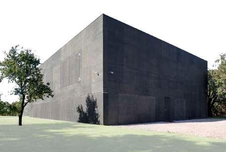
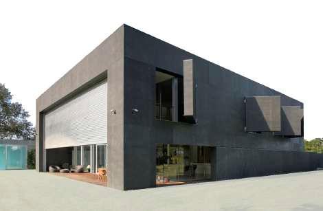
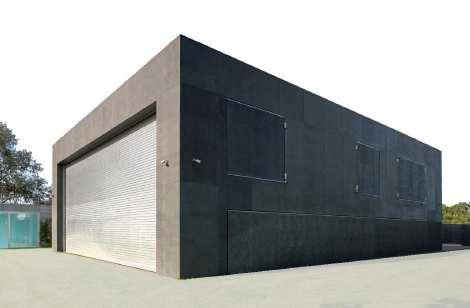
Both the walls and the windows are actuated by electric engine. Teses Electric engines gets actuated through controllers (PLC), afer Controllers get signals from sensors. Tese sensors give
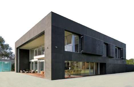
146
Fig 3.1 f : South corner of the interactive safe house
Fig 3.1 g : East corner of the interactive safe house
A. At closed state
A. At closed state
B. At Semi opening state - Windows at 60 degrees.
B. At Semi opening state - Windows at 90 degree.
C. Fully opened state - Windows at180 degree. B. Fully opened state - Windows at 180 degree.
2. Safe house by Robert Konieczny KWK Promes. mp4.
Microclimate
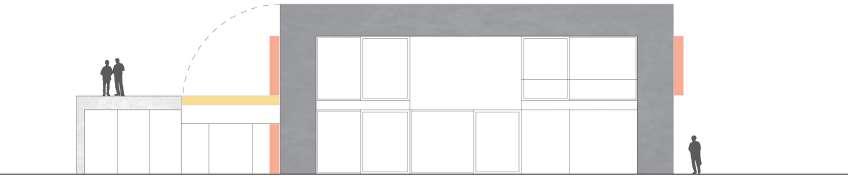
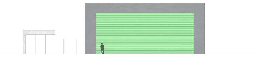
input to controllers and controllers gives signal to actuators and actuators actuates the electric engine. Tis movement in the system depends upon diferent kinds of active sensors like thermal sensors inside the building and sunlight tracking sensors, wind sensors, temperature sensors outside the building. Te thermal sensors sense the heat inside the building keeping interior spaces user friendly. Te sunlight tracking sensors sense the movement of the sun, to avoid direct sun glare inside the building. Te wind sensor outside the building sense the wind condition and maintains the microclimate controlled in the buildings interior spaces. Te temperature sensors outside the building sense the humidity outside the building and gives signal to the PLC which than actuates the actuator, these actuators are designed to control microclimate in the building interior spaces. Hence these active interactive systems control the microclimate of the building.Tis controlled microclimate in the building and around the building makes
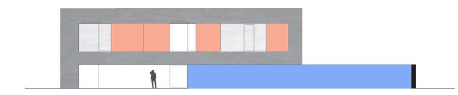
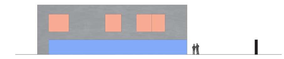
147
Fig 3.1 h: South East Elevation
Fig 3.1 i: South West Elevation
A: Walls and Windows are at closed position.
A: Roll down shutter and bridge are at closed position.
A: Roll down shutter and bridge are at fully opened state.
B: Walls and Windows are at open state.
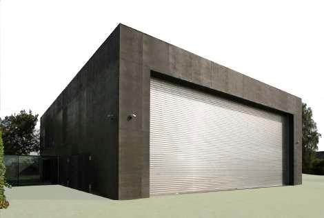
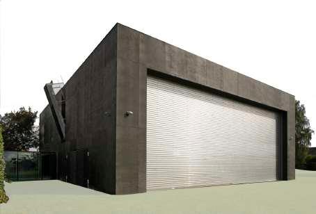
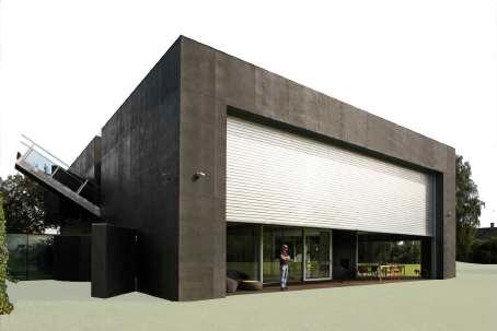
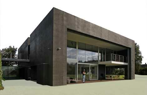
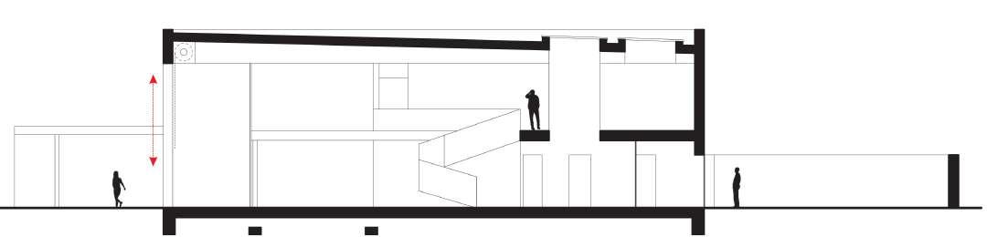
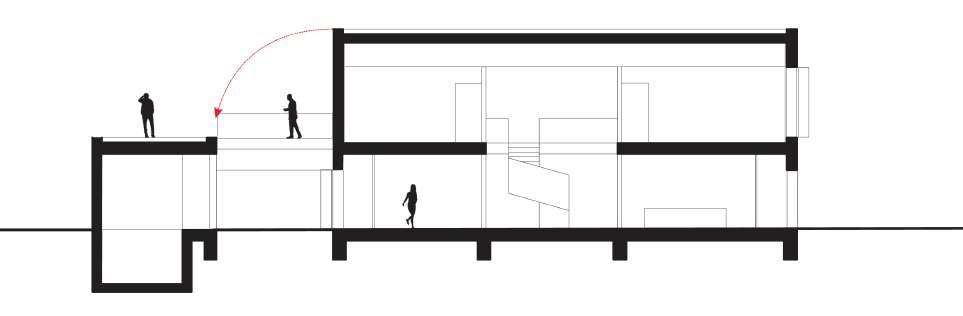
148
A. Closed west corner
B. West corner interactive system gets actuated.
Fig 3.1 j : West corner of the interactive safe house
Fig 3.1 k : Cross Section : Convertible bridge connecting house with terrace of pool and opened widows connection inside to outside landscape.
D. Opened roll down gate and bridge.
C. Semi opened roll down gate and bridge.
Fig 3.1 l : Longitudinal Section: Roll down gate connecting the whole interior of the space with the outside landscape as well as protecting interiors microclimate with respect to exteriors.
Microclimate
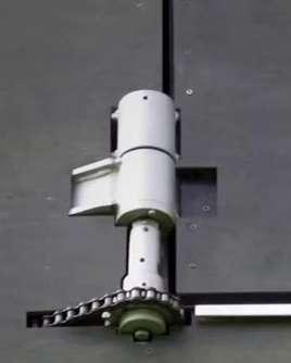
built form more users friendly.
Te interactive safe house opens as well as closes from all four sides; all the interactive elements in the building are along the outer walls keeping the same thickness of exactly 45cm.3
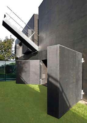
Te longest movable interactive wall of the building is made of light steel trusses whose thickness is similar to the thickness of the walls and is caused by flling it with mineral wool [Fig 3.1o,q]. All the other partitions like the shutters, roll-downgate, or drawn bridge are made up with same material [Fig 3.1 j,k,l,m]
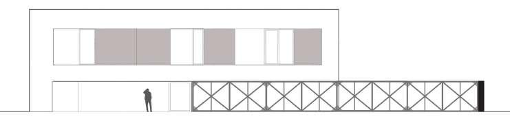
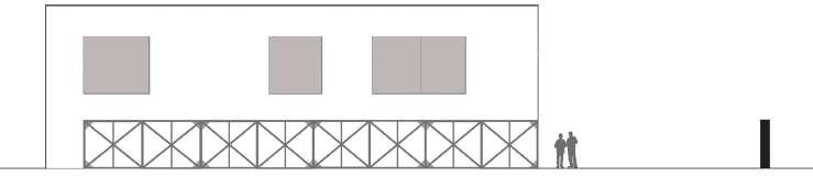
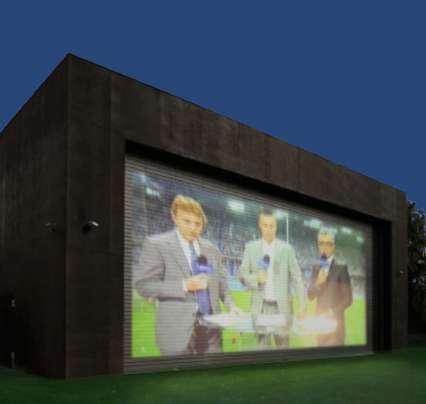
Tis material gives building, excellent insulating properties like suitable warmth and acoustic comfort. All these interactive elements are covered with wood which is waterproof alder plywood painted with dark wood stain. Due to such thick covers the house is very energy efcient. An enormous roll down gate of 14 m long and 6m high, made of white anodized aluminium, is closing the southern elevation of the house. Tis gate also has a possibility to function as a movie projection screen in the night.4 [Fig 3.1 n]
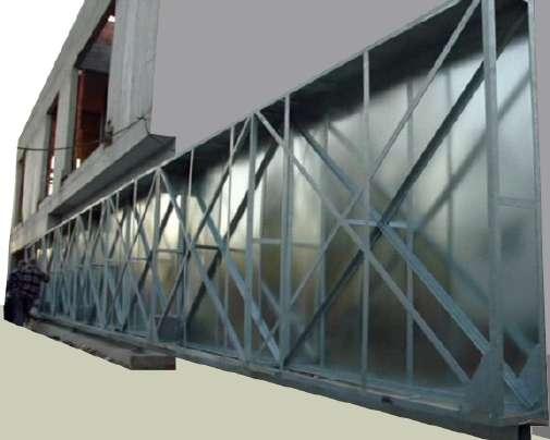
149
Fig 3.1 m : A drawn bridge as well opened windows of south corner.
Fig 3.1 n :Projection on roll down gate at night.
Fig 3.1 o : Steel trusses structure of the sliding walls.
Fig 3.1 p : Chain driven mechanism for windows.
Fig 3.1 q : South East elevation with truss structure of sliding wall and windows.
A. Interactive safe house - Closed.
B. Interactive safe house - Opened.
3. Safe house by Robert Konieczny KWK Promes. mp4.
4. Safe house by Robert Konieczny KWK Promes. mp4.
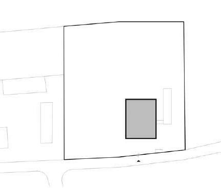
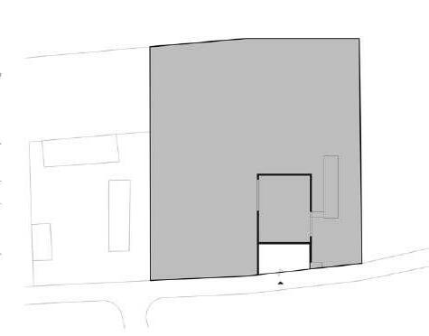

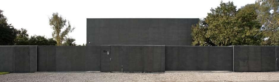
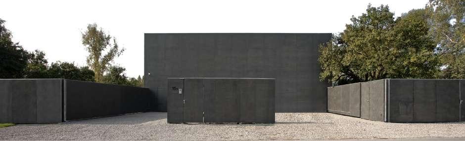
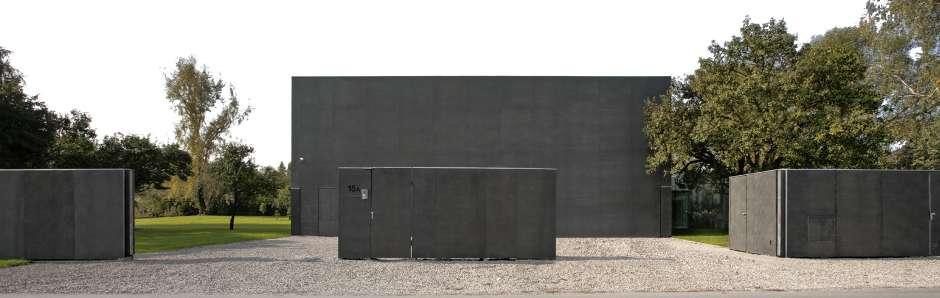
150
Fig 3.1 r : Site Plan
A. Street view of interactive safe house in its closed state.
B. Street view of interactive safe house with opened courtyard from the street.
C. Street view of interactive safe house with fully opened state.
Fig 3.1 s : North East elevation of Interactive safe house from street.
A. Safe Zone - when the interactive house is closed at night
B. Safe Zone - when the interactive house is opened during day.
Microclimate
During the whole day the house is flled with light because of glass partitions and large openings, but at the dusk the process reverses. It’s the house that starts to emanate with warmth and inner light, which get closed in the house’s outline. Tis house not only interacts but also used as safe house, which closes in night to protect its inhabitants and opens to accumulate the energy gathering during the day. [Fig 3.1 r,s]
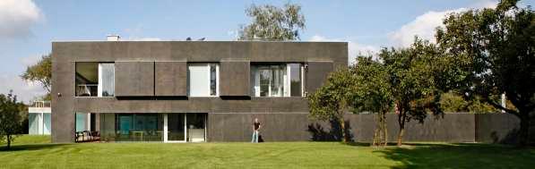

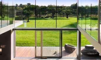
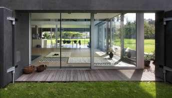
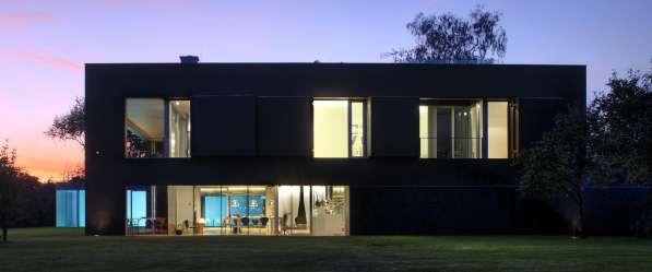
Tis interactive safe house is highly intelligent building which during the day can receive energy when it’s needed, and at the night time can also accumulate it even better when needed (through material properties). Te house sort of behaves identically everyday maintaining microclimatic control of the building and constant cycle is created, and at sunrise the house opens to the garden. Automatically the safe courtyard is created and the house also accumulates energy again. And closes at night to protect itself. Architect Robert Konieczny says “ Tere is something cool and interesting in this house i.e. it behaves identically every day. If you look at a plant it also acts the same each day. Organics of this house is expressed by the way its function.”5[Fig 3.1 t,u,v,w,x,y]
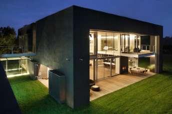
151
3.1 t : South East elevation of house at opened state in morning. connects interior with exterior.
3.1 y: West corner of house accumulate energy in morning to control microcimate and light in night
3.1 x: West North side of house with glass facade, gathering light in morning.
3.1 u : South East elevation of house in opened state at night.
WALLS WINDOWS ROLL DOWN RETRACTABLE 2 11 1 1
3.1 v : South East elevation of house in closed state at night.
NO. OF INTERACTIVE ELEMENTS:
Case Study 3.2: Micro Climate - Retractable Roof and Field
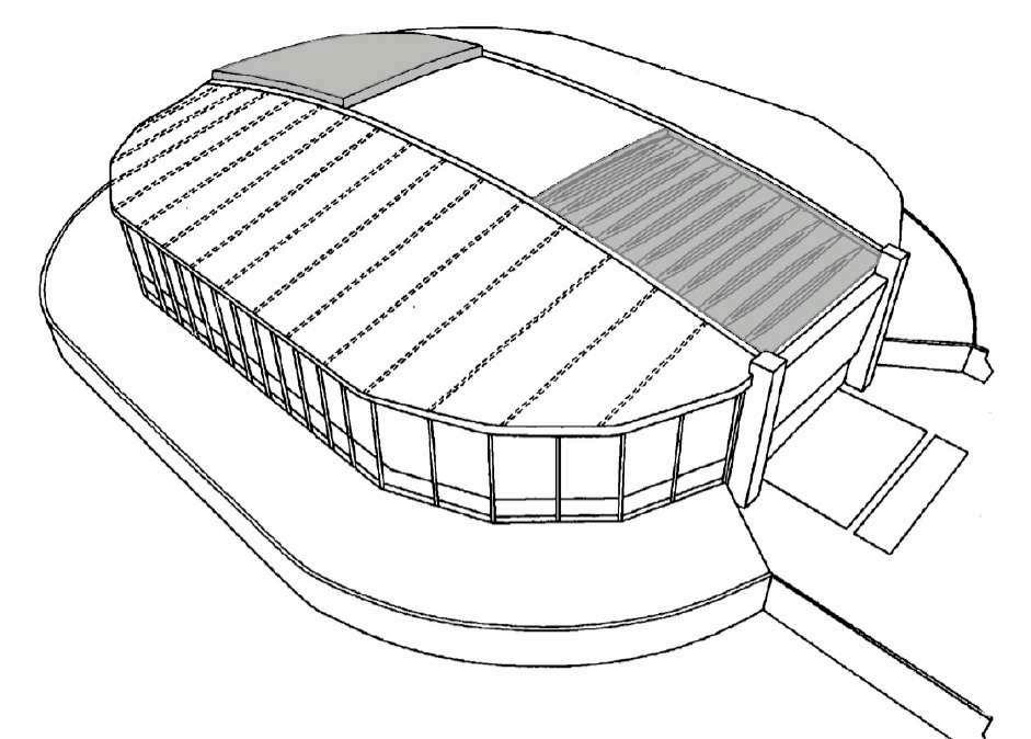
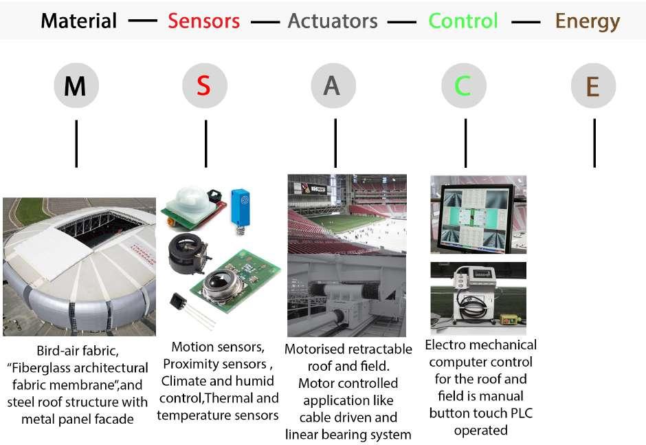
152
FIELDRETRACTABLE
ROOF
RETRACTABLE
Fig 3.2 a: Elements used in interactive system.
Fig 3.2 b: Retractable interactive system in the University of Phoenix Stadium.
Electric current
RETRACTABLE ROOF AND FIELD : The adjustable mechanized structure adapting to change in climate, and providing elegant interactive solutions for the user and becoming more fexible to users.
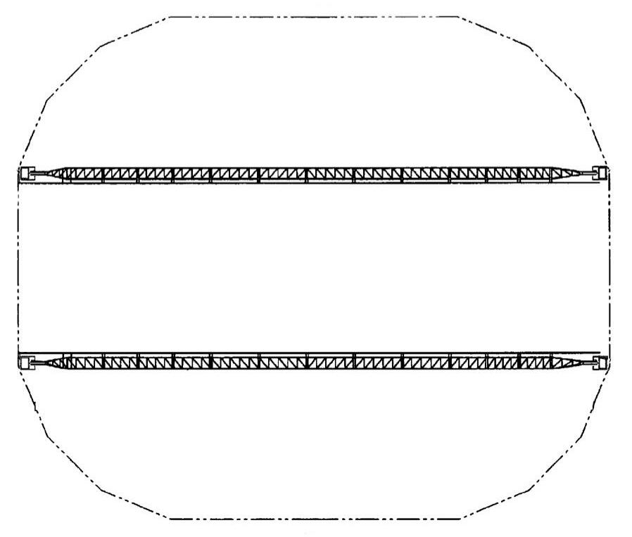
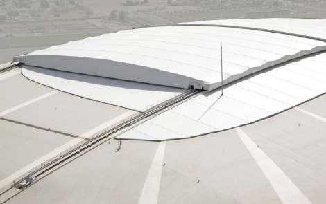
Te University of Phoenix Stadium at Glendale, Arizona, USA- is designed by world-renowned architect Peter Eisenman, and is among the national football league’s newest venues and home to the Arizona cardinals.
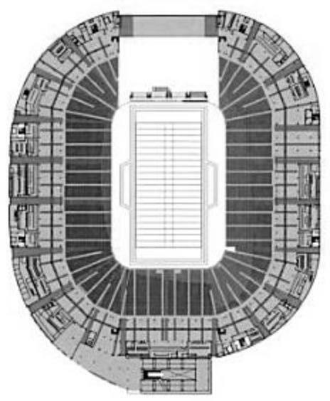
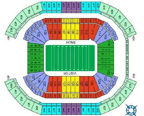
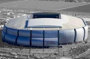
Tis stadium can seat 75,000 people and uses more than 93,000 square feet (8,639 square meters) of highly translucent PTFE fberglass architectural fabric membrane. Te stadium features two large retractable roofng panels exposing the entire playing feld to sunlight while providing maximum shading for fans. Four super columns support the roof. Two 700-foot long trusses rest on the super column. Each truss is 87 feet high at its tallest point and weighs about 1,800 tons. Te top of the roof is 206 feet above grade. Each roof panel weighs 550 tons. Tese panels, which roll on a steel roof structure, open or close in about 12 minutes. Te roof can remain closed for efcient air conditioning to give people much-needed relief in the summer months, or can be opened to take advantage of the Valley’s cooler climate cycles. Te stadium has an open, airy feel, even when the roof is closed.1 [Fig
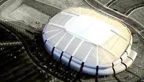
153 Microclimate
N N
3.2 a,b,c,d,e,f,g,h]
Fig 3.2 c: Retractable roof at opened state.
Fig 3.2 d : Retractable roof at closed state.
Fig 3.2 e: Plan with four super columns.
Fig 3.2 f: Each pannel rides on the curved roof rails via eight transporters.
Fig 3.2 g: Columns are connected through brunel Trusses.
700 87 17 1,800 Length Height Width Weight Feet Feet Feet Tons
Fig 3.2 h: Brunel Trusses- Two trusses made from Belgium steel holds up the stadium’s 5600- ton roof.
Brunel Truss
1. University of Phoenix Stadium - Projects - Birdair, Inc..pdf pg- 1.
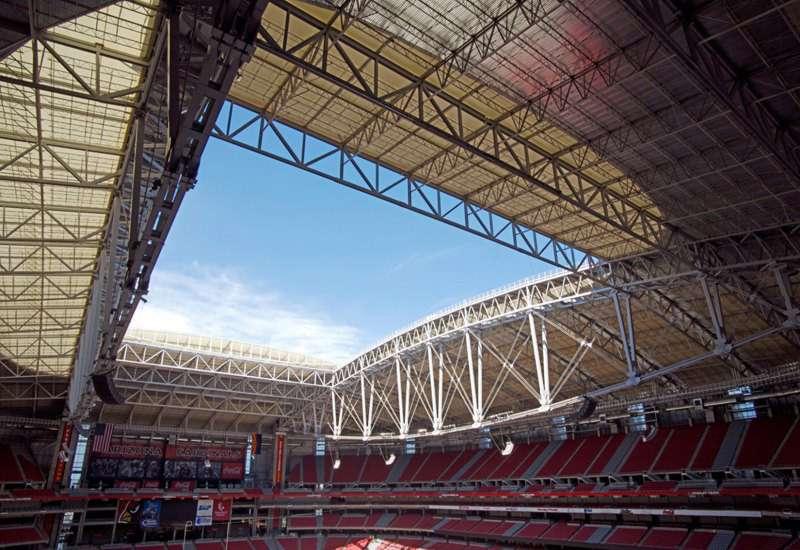
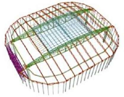
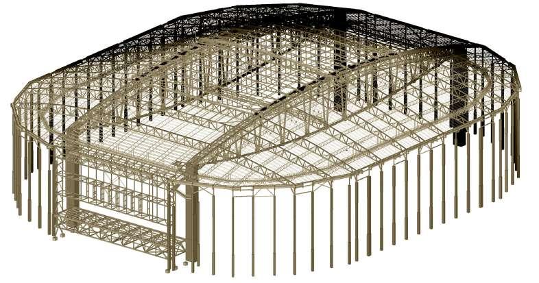
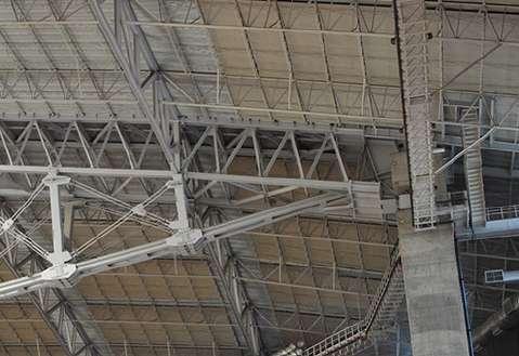
154
Fig 3.2 i: Overall Structure of stadium with two main arches in green.
Fig 3.2 j : Junction of super column with brunel truss.
Fig 3.2 k : Pheonix stadium isometric view with the metal structure.
Fig 3.2 l : Two curved trusses and two linear horizontal trusses together transfering the load of the roof to the four super column.
Microclimate
And the second is retractable grass feld, which rolls out of the stadium on a 18.9 million pound tray, residing outside of the stadium except for football and soccer events. It is the frst of its kind in North America. Te grass feld remains outside the stadium in the sun, until game day getting the maximum amount of sunshine and nourishment, eliminating humidity problems inside the stadium and providing unrestricted access to the stadium foor for events and staging. Te site has the stadium situated along a slight northwest to southeast axis for maximum sun exposure for feld in the outboard position.2
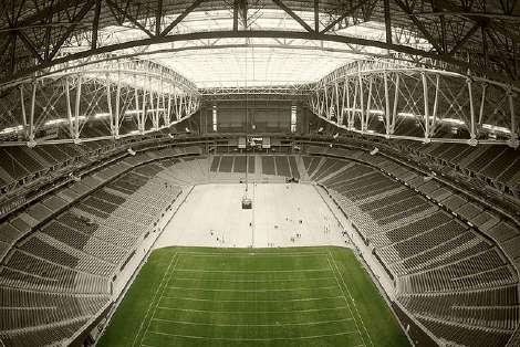
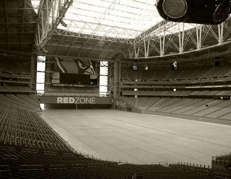
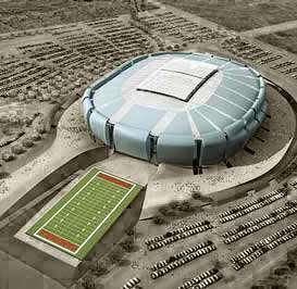
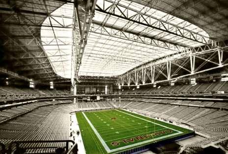
[Fig 3.2 m]Both of the systems work on the same principle of Sensors, actuators and controls but the only diference here is there application. Te scale of these retractable devices is so big that to make them move under such climatic conditions, has to be very accurate so that they work precisely within the change in micro climatic condition. For which sensors and cameras are used to track their accurate movement, actuators are controlled by PLC and PLC controls the movement in actuators by sensing the microclimate. [Fig 3.2 n]
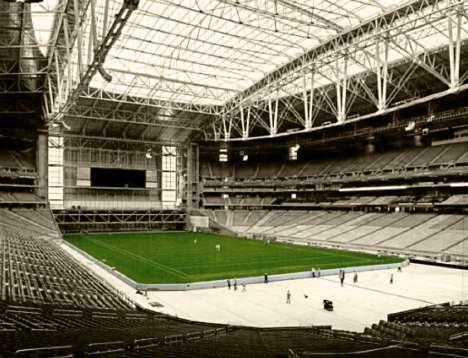
155
Fig 3.2 m : Field retracted out of the stadium to get proper sunlight. The retractable roof is closed as there is no issue of
Fig 3.2 n : The university of pheonix stadium retractable feld.
A. Field is inside the stadium .
B. Field mechanism is actuated by local control as well as feld is half retracted.
C. 50% of the feld is moved out through actuated wheels
D. The fled is totally retracted out and now the area left can be used for public events.
2. University_of_Phoenix_Stadium.pdf pg-1,2.
Uni-Systems designed, manufactured, and installed the mechanization for the retractable roof and feld at the University of Phoenix Stadium. Te cable driven roof bi parts at the 50-yard line and rests over each end zone when in the open position. When closing, the roof panels drive uphill along rails set in a vertical arc. Twin translucent roof panels efortlessly angle toward one another from a 14 degree tilt above the end zones to a fat 0 degrees at the center of the stadium.3[Fig 3.2 o,p]
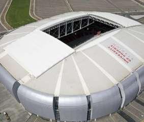
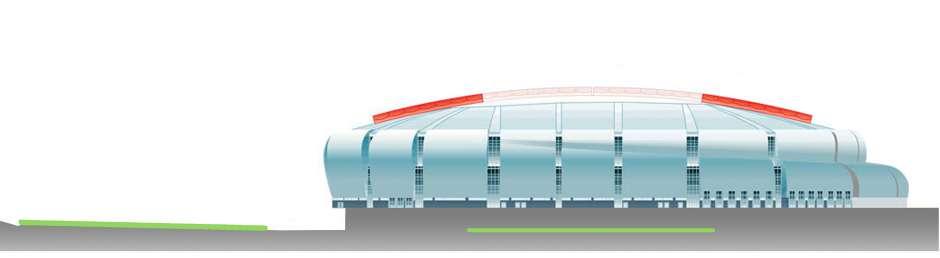
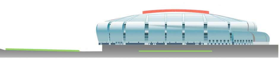
A computer-controlled system is used to operate, monitor and troubleshoot the retractable roof. Te computer screen displays the speed and position of the roof panels, along with the status of motors, brakes, operable rail clamps and other components. Cameras on the roof panels send real-time images to the computer screen for monitoring. Te name and location of any
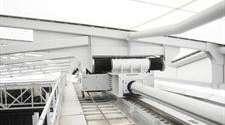
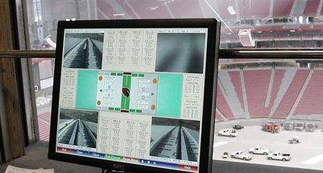
156
Retractable Roof Retractable Field Retractable Roof Retractable Field
Tilt 0 Degree
14 Degree
Fig 3.2 o : When the pannels are open, it exposes the entire playing feld. Size of the roof opening is 240 ft wide by 360 ft long.
Fig 3.2 p : The opening and closing of retractable roof and retractable feld at university of pheonix stadium, behaving like an interactive elements.
Fig 3.2 q : Monitoring and controlling the movement in the interactive roof through sensors and cameras , from computer at the control room.
3. University_of_Phoenix_Stadium.pdf pg-1,2.
faulted components are also displayed, and full diagnostics and help screens simplify troubleshooting. A secure internet connection allows Uni-Systems engineers to remotely monitor the system to provide real time support to on-site operators.
Te 9,450-ton (8.5 million kg) natural-grass playing feld is driven in and out of the stadium along steel rails at the touch of a button. Storing the feld outdoors allows the stadium to be used for conventions and other events and simplifes maintaining a healthy grass playing feld. 4 [Fig 3.2 p,q,r,s]
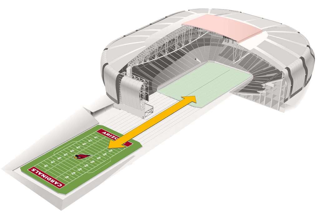
Eight panel trusses makes the metal frame work that connects the roof with the transporters.
Bull gear, attached to the cable drum and rotated by the motors.
The transporter: Rides along the rail girder, allowing the roof to open and close.
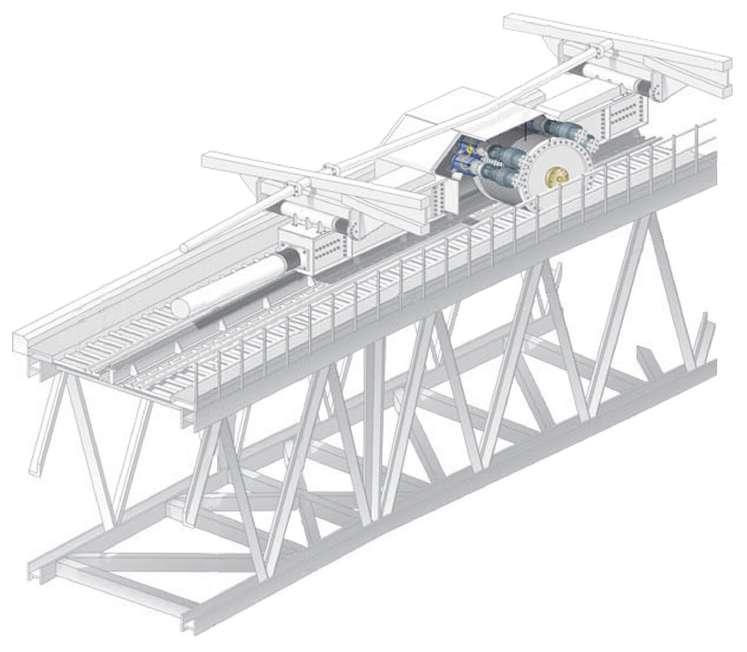
Linear bearing: Allows the pannel trusses to sway.
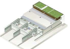
Transporter link, which connects seven sets of transporters on each roof.
4. http://www.uni-systems.com/en/solutions/components/computer-control#control-systems.
157
Microclimate
Transporter girders, wheel behind girders.
Rail. Rail girders. Cables. Cables trough.
Motor and brake.
Cable drum with grooves that grip and advance the cable.
Fig 3.2 r : Detail mechanism of one customized actuator to operate each pannel.
Fig 3.2 s : Interactive feld and roof at the university of pheonix stadium.
Fig 3.2 t : Detail of Interactive feld next page.
On non-game days, the playing feld resides outside the stadium where conditions for maintaining grass are ideal. Engineers designed the feld to react like a traditional grass playing surface, so that players feel comfortable, whether they are running, jumping or tackling each other .
Te local control system has been used to operate the retractable feld. Te portable control station plugs into the leading edge of the interactive feld, allowing the operator to closely monitor the moving equipment during operation. Te operator simply presses the RUN pushbutton, and the 9,450-ton feld begins to move. Te low-profle feld is designed with the grass surface , 42 inches above the concrete. 5 [Fig 3.2 u,v]
Te roll out feld travels at a speed of 11.5 feet/minute (1/8 mph) ; it takes approx. 75 minutes to travel approximately 741 feet. Te feld is 234 feet wide , 403 feet long and 39 inches tall. Field tray rests on 13 steel rail tracks embedded in concrete that sit nearly fush with the facility’s foor and moves in and out of the stadium on 546 steel wheel assemblies (42 rows). 76 of the wheel sets are powered by a 1- horsepower motor (total = 76 hp). Te feld will support approximately 94,000 square feet (over 2 acres) of natural grass. Te grass is Tifway-419, a Bermuda hybrid. It was planted by using stolons, or plugs, that provide the best long-term feld conditions. Te tray has a fairly sophisticated irrigation system that works on timers and can be customized. Te water will drain through a 1-inch-deep mat and several pipes that lead to a main drainpipe underneath the feld tray. A few inches of water will remain in the tray while the feld is in play to keep the grass moist. Afer the feld is driven outdoors, a clean, fat, well-positioned event foor is exposed, ready to fully support public venues.6 [Fig 3.2 t]
woven material that only allows water to penetrate
5. http://www.uni-systems.com/en/solutions/components/local-control#control-systems
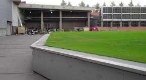
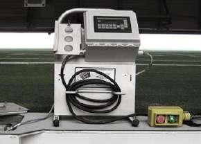
6. http://www.uni-systems.com/en/projects/featured-projects/university-of-phoenix-stadium.
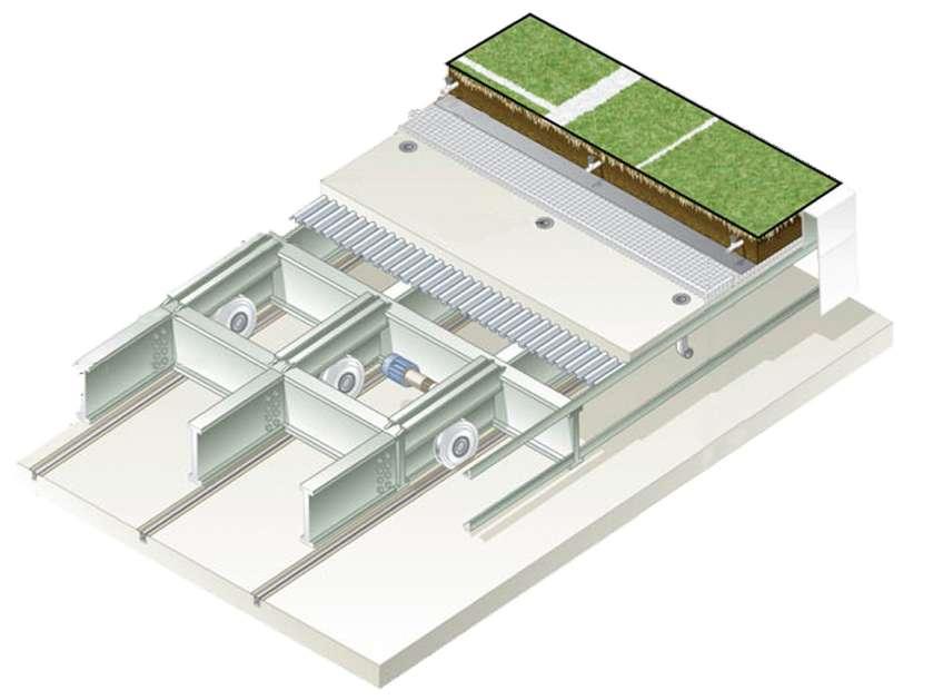
158
The natural grass called Tifway- 419, a Bermuda hybrid, which is used on some golf courses.
Irrigation piping and in-ground sprinkler heads
13 Tracks embedded in the concrete, guide the feld in and out of the stadium
Steel
Wheel
One
Drainpipe
3 inch gap between the frame and the ground
Frame
assembly
horsepower motor Corrugated
steel
Fig 3.2 u : Control unit of interactive feld.
Fig 3.2 v : The interactive feld is moved out of the stadium and is 42 inches above the ground level.
Fig 3.2 t :Detail of Interactive feld as well as customised actuator with in the system with its functioning.
Microclimate
Both the roof and feld system is actuated by mechanized systems. Cable drive system and Stress Release system are mechanized systems in the roof. Te Stress Release system consists of linkage suspension, and linear bearing systems controlled by computer. Track Rail system is the mechanized system in feld, which is controlled by local controls.
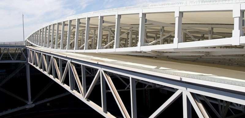
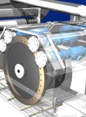
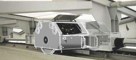
[Fig 3.2 w,x,y]
CABLE DRIVE SYSTEM:
Te University of Phoenix Stadium interactive roof is moved along the arced travel path by a cable drive system mounted to the two roof panels. Each roof panel is equipped with four cable drums that spool cable anchored to the fxed roof above the 50yard line. Four 7.5 horsepower motors power each cable drum, moving the roof at a maximum speed of 25 feet per minute. 7
159
7. Drive_Systems.pdf
Fig 3.2 w : Cable Drive System. Four 7.5 HP Motors
4’ Cable Drum
1.5” Cable
Linkage Arm
Fig 3.2 x : Major components of cable drive system.
Fig 3.2 y : Metal frame structure of interactive roof panel, which will be carried out and in by
Transporter
Rail
STRESS RELEASE SYSTEM:
Linear bearing:
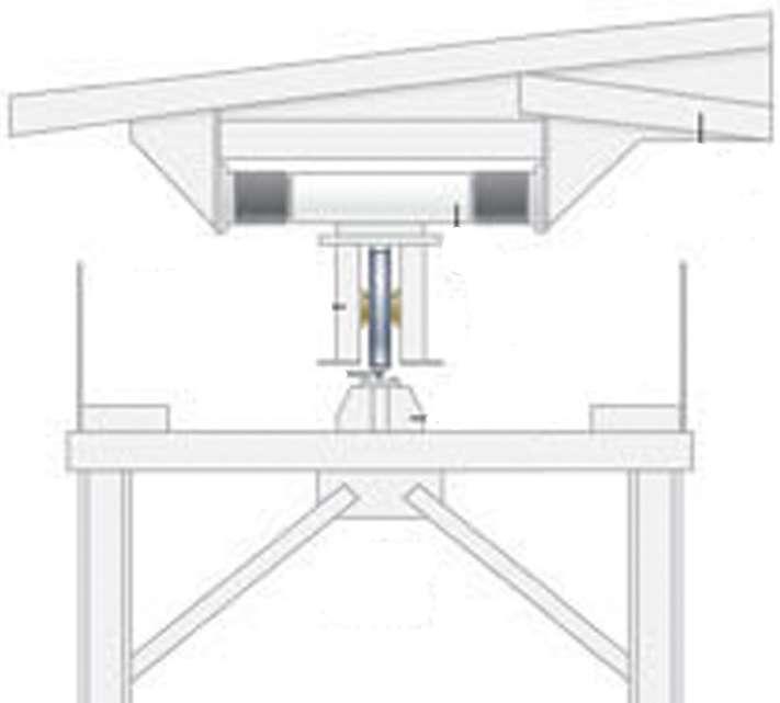
Te University of Phoenix Stadium retractable roof is comprised of two low-profle panels that are driven along a parallel rails on either side of the stadium bowl. A lateral release system was required that would accommodate relative movement between the fxed building structure and the retractable roof caused by wind, thermal expansion and other structural forces. Te limited vertical space between the roof panel and the fxed building structure made previously designed lateral release systems unusable.
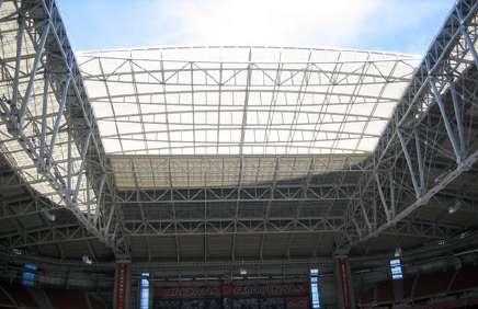
[Fig 3.2 z,a1]
Linear bearings on the west side of the stadium are connected to the retractable roof at both ends of the guide shaf. Each guide shaf is encased in a movable collar mounted to the transporter, which allows for 36 inches of relative movement between the roof panels and the transporters. Tis allows the wheels on both sides of the roof to stay engaged with the rails regard- less of relative lateral movement.8 [Fig 3.2 a2]
Linear bearing
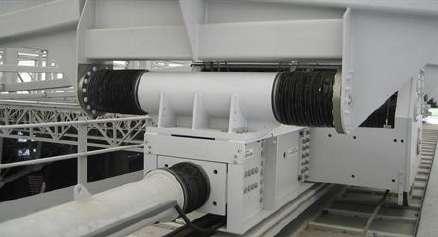
Rail girders
Brunal Truss
160
Pannel Truss
Always on the track the panel truss can shift + -
Fig 3.2 z : One side roof covered pannel drives along a parallel rails.
Fig 3.2 a1 : Linkage bearing.
Fig 3.2 a 2 : Placement of Linear bearing. 8. Stress_Release_Systems.pdf, pg-1.
Microclimate
Linkage Suspension:
20 transporters move the retractable roof. Each transporter is equipped with two traction wheels. Te fve transporters (actuators) in each quadrant are connected onto a train by linkage suspension arms that are pinned at each end, and rotate vertically as needed to accommodate changes in the steel rails. Te linkage suspension system evenly distributes roof weight throughout movement, and prevents any of the wheels from becoming high-centered or overloaded. 9 [Fig 3.2 a5]
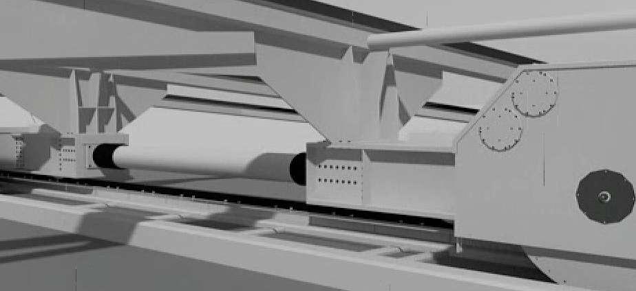
Stadiums and arenas utilizing bird air tensile roofs additionally beneft from natural sunlight that penetrates the interior, promoting optimum day lighting while consideably reducing electric lighting requirements. And the retracable feld improves income opportunities and optimizes event-scheduling fexibility by hosting non-football events throughout the 365 days. As traditional football stadiums were used only for 10-20 dates a year. [Fig 3.2 a3,a4,a6,a7]
161
Fig 3.2 a3: Trade and customer show inside the stadium.
Fig 3.2 a4: Exterior public event on the feld.
Fig 3.2 a5: Linkage suspension between two actuators for smooth drive .
Fig 3.2 a6: Wrestling event inside the stadium driving feld outside.
Fig 3.2 a7: Team building events inside the stadium driving feld outside.
Actuator 1
Actuator 2
9. Stress_Release_Systems.pdf, pg- 3.
Logic diagram:
In interactive safe house actuation is done on the bases of very simple logic, that is when the sensors senses the change in microclimate it sends the data to the controllers and controllers manuplates the data and accordingly activates the actuation to control the microclimate inside the building.
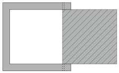
All the interactive elements in the house can be remote controlled or can be controlled through logic.
Te red arrows here represent the acuation is at rest condition and green arrow here represents the end result afer actuation.
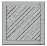
INFERENCE :
This chapter moves one step ahead from the complexity from the scale of interior interactive system to the scale of architectural interactive system. Architectural interactive system incorporates within the elements of built form such as openings like windows, doors, to the load bearing structure like walls etc.
The application of interactive system in architecture functions slightly diferent from the interior. Here the functioning of interactive part in the building elements modifes the system from the way of sensing, to the actuation, through control with the help of energy to get controlled microclimate inside the building.
The interactive safe house is the example where the interactive system in architecture has been incorporated in open able window, slide able walls, and roll down southwest gate and retractable bridge.
For the accurate performance in such system, the customized mechanisms for the actuation were created and strong sensors to give long duration signal were placed. The sensors, which simultaneously give signal while sensing, till the full actuation for such a long durations, has to work accurately with respect to the external micro climatic conditions through controllers and energy source. Sensors are placed outside the shell of the built form, which keeps S A
E R C
162
Interactive elements is actuated fully Interactive elements is at rest Remote
Wind direction
tracks on the movement of the sun to protect the interior of the building from the direct sun glare as well as temperature gain. Together with controlled microclimate conditions inside, as well as around the building by the innovative interactive system providing user friendly interactive surrounding.
Sensors sensing the wind speed and controllers regulating the speed of actuator so that the wind does not damage the PTFE panel.
Logic diagram:
In interactive roof and feld actuation is done on the bases of very simple logic but complicated machanisms, the actuation on roof can be regulated through remote or by sensors. Remote is used when there is functional need and sensors are used for controlling microclimate inside the stadium. Actuation on the roof is done through the live observation with the help of cameras. And the feld is removed out to control humidity and to give sunlight and fresh air for grass.
Te red arrows here represent the acuation is at rest condition and green arrow here represents the end result afer actuation.
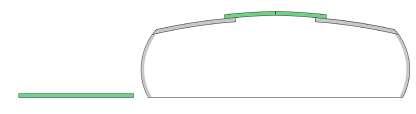
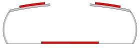
E R C
But at the University of Phoenix stadium the scale is so huge as well as a whole system is so complex that the sensors and cameras has been placed to observe the smooth working of actuator by the computer controller around such a dynamic micro climatic condition outside the building. For instance the interactive roof system has two panels, which actuates. These panels are placed at the top most height of the stadium, which is curved at the ends and straight at center. To move the panels accurately above the people on a curved path under uncontrolled natural wind is a diferent task all together. Due to height, the wind pressure on the roof panels is highly critical, the force applied for the movement has to be taken care so that the roof panels actuates accordingly without any failure and disturbance. And at the time when there is less wind the speed will be again observed by the sensors and controllers to maintain it accordingly. S
A
Interactive elements is actuated fully to control microclimate inside.
Interactive elements is at rest as microclimate is in controlled state.
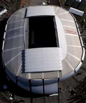
163
Microclimate
Due to inside and the outside actuations of the feld in the stadium, the humidity issue inside the stadium is resolved hence when the feld is actuated outside the stadium and the roof closes with the help of actuators. The stadium transforms it self to become a social hub for diferent kinds of events happening on the huge concrete foor surrounded by controlled microclimate conditions.
Hence to control the microclimatic condition for such a large-scale project the interactive system will be designed diferently with the application of sensors, actuation and control has to be taken in consideration accordingly.
Now in next chapter we will see how these interactive systems further improves branding quality as well as experience in the interior of the commercial building for users.
164
CHAPTER - 4
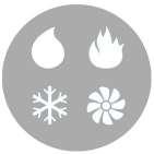
165 Branding
USER LIGHT MICROCLIMATE BRANDING
BRANDING
Branding:
Interactive system changes the perception of space from static to dynamic experience and responds to user, as well as controls microclimate, from small-scale residences to large-scale stadium. This system being so dynamic and being an experience generator, can also improve the quality of branding inside the interior with such principles of sensors, actuators, controllers and energy, to change dynamism in space, behavior and experiential impact on the customers to improve brand identity and brand image.
What is brand?
Brand is a name, term, design, symbol or a feature that distinguishes one seller’s product from those of others. Brands are used in business, marketing and advertising.1
Brand certainly encompasses the logo and the full visual position created by a strong brand identity. It also includes to the content, messaging and story telling. Customer service and the client experience is also a part of a brand. The idea of a reputation is a critical portion of defning the word brand, where brand image comes into picture.2
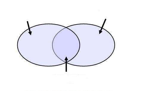
Brand image:
Brand image is impression in the consumers’ mind of a brand’s total personality (real and imaginary qualities and shortcomings). Brand image is developed over time through advertising campaigns with a consistent theme, and is authenticated through the consumers’ direct experience.3
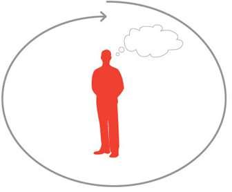
1. https://en.wikipedia.org/wiki/Brand.
2. http://www.visiblelogic.com/blog/2013/02/logo-brand-identity-brand-what-is-branding/#sthash.gg2gySYb.dpuf. 3. http://www.businessdictionary.com/de
166
fnition/brand-image.html#ixzz3qF6cXmeC BRAND Perceived emotional corporate image as a whole Commit Support Target Audience Brand Awareness Convince A BRAND IS MORE THAN JUST A LOGO IT’S AN EXPERIENCE IDENTITY IMAGE How the brand owner (management) defnes what the brand is How consumers percieve the brand Goal as much overlap as possible
Fig 4.1: Defning brand
Fig 4.2 : Brand is Experience
Fig 4.3 : Brand meaning
Fig 4.4 : Brand identity and brand image
Brand Identity:
A brand’s visual identity is the overall look of its communications. Efective visual brand identity is achieved by the consistent use of particular visual elements to create distinction, such as specifc fonts, colors, and graphic elements. At the core of every brand identity is a brand mark, or logo. 4
Brand identity is a unique characteristics of an organization, it represents how an organization wants to be perceived in the market. An organization communicates its identity to the consumers through its branding and marketing strategies. A brand is unique due to its identity.
Brand identity includes following elements - Brand vision, brand culture, positioning, personality, relationships, and presentations. Brand identity is a bundle of mental and functional associations with the brand. Associations are not “reasons-to-buy” but provide familiarity and diferentiation that’s not replicable getting it. These associations can include:
Signature tune for example -Britannia “ting-ting-ta-ding”.
Trademark colours for example - Blue colour with Pepsi. Logo for example - Nike.


Tagline for example - Apple’s tagline is “Think diferent”.

- Levi’s “ GO FORTH”.

- BMW “The ultimate Driving Machine. The brand can be perceived as a product, a personality, a set of values, and a position it occupies in consumer’s minds. Brand identity is all that an organization wants the brand to be considered as. It is a feature linked with a specifc company, product, service or individual. It is a way of externally expressing a brand to the world. 4. https://www.google.co.in/?gws_rd=ssl#q=brand+identity

167
Branding
IDENTITY
Visual
aspects that form part of the overal brand
Fig 4.5 : Defning brand Identity
Fig 4.6 : Trademark, logo and Tageline of brands.
Interactive systems when designed for banding in commercial spaces can be manifested through interactive media as well as through changing the experience of static space to dynamic moving or kinetic elements in the space. Creating strong impact of branding identity and image on customers mind. Such interactive systems used for branding to upgrade the brand image can be known as interactive branding.
Interactive Branding describes the use of means and methods for the formation and management of trademarks in the background interaction. Interactive branding through interactive media and kinetic elements focuses on the refnement of the representation of a mark at the interface between consumers and supply like information, service, control and communications. Interfaces to interactive systems in interactive media, include all input and output options available to a user in the context of so-called “contact points” (TouchPoint); Places and situations in which customersor users enter into exchange with digital systems. And the interface of dynamic elements includes the sensory systems for the user, which will sense the motion and some times behavior of the user. From the user’s point of view the use of an interactive system resulted in the so-called user experience.
Interactive Branding staged and orchestrated the individual dimensions of the user experience in terms of brand-relevant aspects, or to be achieved brand awareness or experience. 5 5. https://translate.google.co.in/translate?hl=en&sl=de&u=https://de.wikipedia.org/wiki/Interactive_Brand-

168
ing&prev=search Interactive system Branding Interactive Branding Kinetic, Dynamic or Tactile based interface Visual Media based Interface Past and Present Awarness / Experience Customer OR USER
Fig 4.7 : A diagram explaining interactive branding.
Branding
We will further study such interactive branding in the case of two world known brands;
LEVI’S and BMW
Levi’s is a brand of denim jeans. LEVI’S showroom in Bangalore is an example where interactive systems like interactive Rivet wall and wall of Levi’s history with interactive touch screen has been installed.
And BMW, which is an automobile brand, best known for ultimate driving machines and innovative technology as well as with the research based concept cars. BMW has a remarkable history in automobile designing, which has been incorporated in BMW museum, in Munich. An interactive system with interactive media and kinetic elements has been incorporated which improves brand image as well as identity.
169
BRANDING SYMBOL DESIGN FEATURE BUSINESS MARKETING ADVERTISEMENT LOGO VISUAL BRAND IDENTITY CONTENT MESSAGING STORY TELLING FONTS COLOUR GRAPHIC ELEMENT BRAND MARK UNIQUE CHARACTER STRATEGIES POSITIONING RELATIONSHIP PRESENTATION MENTAL FUNCTIONAL ASSOCIATION FIMILARITY SIGNATURE TRADE MARK TAGLINE EXPRESSION SERVICE INDIVIDUAL BRAND CULTURE BRAND VISION CUSTOMER EXPERIENCE REPUTATION IDEA BRAND IMAGE PERSONALITY THEME COMMUNICATION
BRAND INTERACTION INTERACTIVE SYSTEM INTERACTIVE BRANDING
Fig 4.8 : Key words connecting or mapping Brand and Interactive branding
Case Study 4.1: Interactive Walls - Levi’s Rivet Store
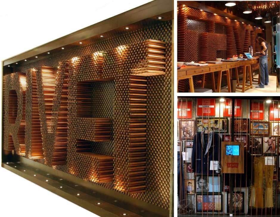
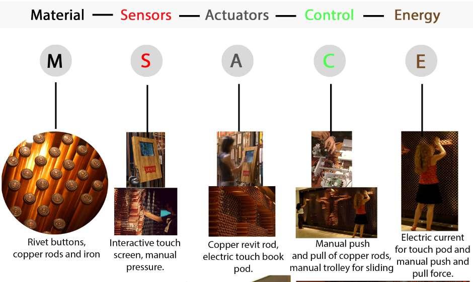
170
Fig 4.1a: Elements used in interactive system.
Fig 4.1a: Elements used in interactive system.
Fig 4.1b: Interactive Rivet wall and histroy of levi’s interactive wall.
INTERACTIVE WALLS: The interactive Rivet wall , a wall which invites the customers to engage and explore…..play!. AND an interactive history wall; a process of representing a 150 years old global brand in an interior space.
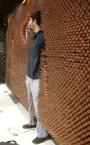
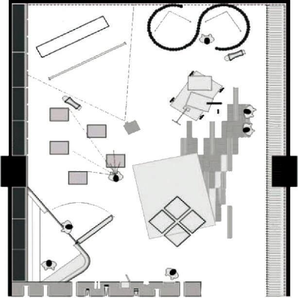
The Revit store museum at Hotel Leela Galleria in Bangalore is designed by Lotus studio and Codesign, Delhi completed in 2005. A 1000sft space is an icon store for premium products of Levi Strauss. Designing the store, the architects were determined to challenge the conventional notions associated with retail. ‘The aim was to create a sense of mystery, while evoking an image of the “premium”-ness and style related with this brand. The designers wanted to give the store a gallery-like ambience, which would allow for a complete revamp of display overnight and allow for other events to be held in the store. A prime concern was also to showcase the tremendous heritage and history of the brand by using a combination of classical and cutting-edge technologies.1
The design of the store is inspired by the process of industrial craft that goes into the making of the product. The whole store was handcrafted utilizing materials that are used in the product – copper, iron, and denim – all worked onto plywood and treated like inserts into the raw concrete shell of the site.
171 Branding
1.
http://www.insideoutside.in/inside-outside/issue-magazine/2719/meet-lotus-rivet
Page 8 of 16.
Interactive Rivet wall
Interactive wall of Levi’s History.
8715 10450 Entry Front Facade Changing Room RedArea Displayonwoodencrates RedLoop Walk in vault for storage The Cashier Hard wood fooring with teak fnish Storage wall Changing Room Saddle
Denim displayed in polarised glass cubes which reveal the product magically
Fig 4.1c: Customer or user playing with revit inetarctive wall.
Fig 4.1d: Plan- Levi’s Rivet store museum at Hotel Leela Galleria in Bangalore
Lotus studio has incorporated two interactive elements, one is Interactive Rivet wall and another is Interactive history wall, to heighten the retail experience for the user and to improve brand identity as well as brand image for the Levi’s Strauss.

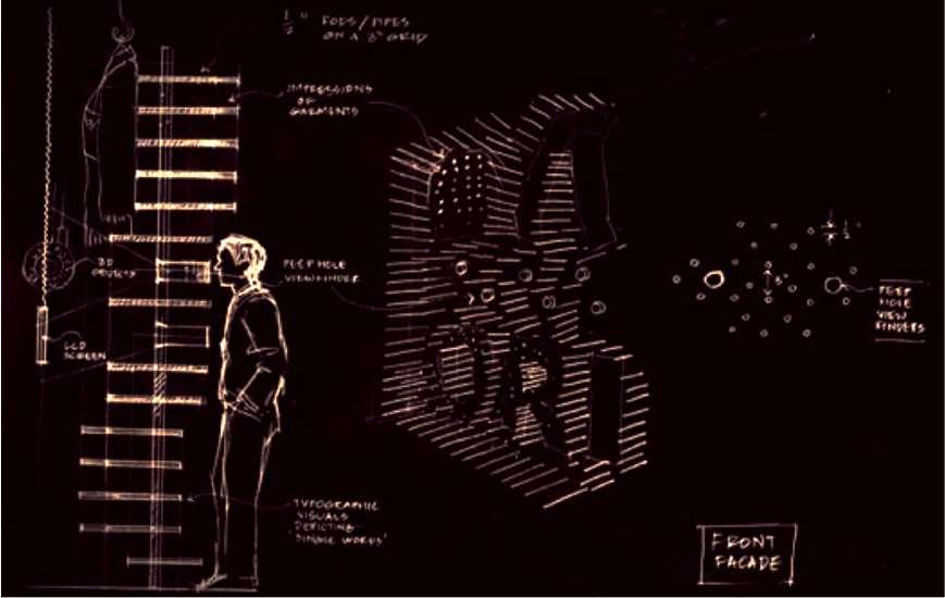
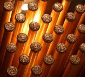
The interactive Rivet wall; A tactile interactive element is designed where the customer is encouraged to play with the store, the facade wall constructed with 8000 copper rods, 16000 buttons and denim, which slides into giant perforated wall. Creating three-dimensional patterns, it encourages the customer to play with the entire facade, and in turn, allows for niches framing the products, to be formed on the rear of the wall, which is inside the store. These copper rods act as actuators when come in contact with the users. As this interactive wall is manually operated by customers, the control will be depending upon the pull and push action on the rods by the customers to create patterns in the wall. Customers playing and creating patterns spending time and getting engaged with the wall is the way interaction takes place. This wall is at the front facade of the store. 2
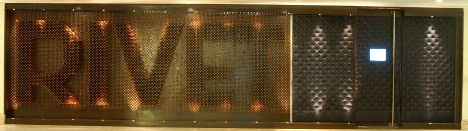
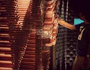
172
Peep hole view inside 1/2” 8” Typographic
Peep hole view inside Impression of Garments 1/2” Rods / Pipes on a 8” grid 3D Graphics LCD Screen Front
visual
depicting single words.
Facade
2. http://www.insideoutside.in/inside-outside/issue-magazine/2719/meet-lotus-rivet Page 9 of 16.
Fig 4.1e: Rivet and copper rods in revit interactive wall
Fig 4.1f: User interacting with rivet wall
Fig 4.1g : Front facade of Rivet Levi’s store.
Fig 4.1h : Sketch and details of Front facade - Rivet interactive wall.
But when customer enters into the store, one encounters the interactive history wall bordering on side of the store. The interactive history wall ; is a visual and virtual interactive walk through a hundred ffty years (1850-2000) of Levis heritage and world history. The history wall is a 34ft long wall that narrates the story of the Levis brand through a graphic-rich archive of advertisements, photographs, catalogs, letters, historic garments and replicas of vintage products of the particular era, running together with concurrent world history.
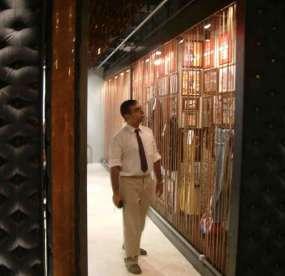
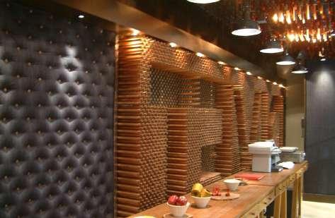
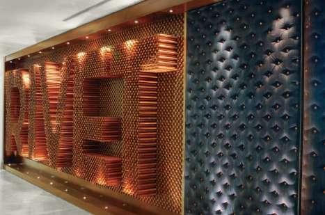
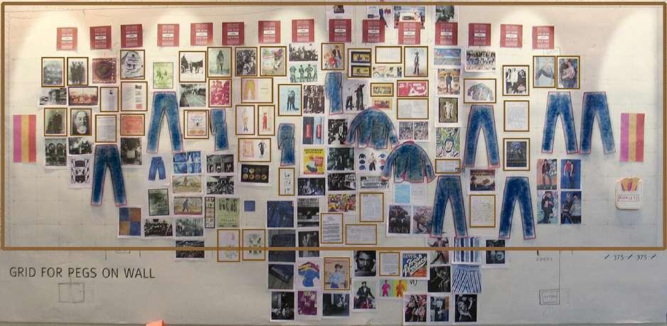
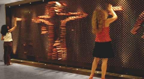
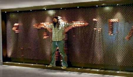
173 Branding
1860s 1870s 1880s 1890s 1900s 1910s 1920s 1930s 1940s 1950s 1960s 1970s 1980s 1990s 2000s
Fig 4.1i : Users playing as well as creating patterns by pulling and pushing the copper rods of the revit wall
Fig 4.1j : Front and back of rivet interactive wall.
Fig 4.1k: Customer entry view.
Fig 4.1l: Planning and process for the history of wall.
In front of this wall a seamless narrative was created that engages the user with the brand’s travelogue through time. An interactive touch-screen, combined with the customized electronics, slides along the length of the history wall and automatically corresponds to the period of time behind it. Stop within a certain decade, and you can delve deeper into the history of the company in both audio and video formats. This is more like an electronic book, which turns pages as you move along the Wall. In this wall the sense of touch and the movement of interactive book on the track acts as sensors and the controllers. The electronic interface plays the role of actuators. The resultant of act of sensing, controlling and actuating gives customers the value of the Levi’s Strauss.3
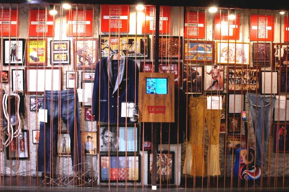

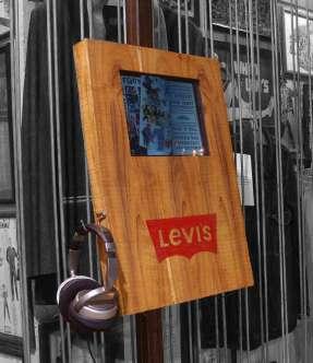
174
1980s 1990s 1970s 1960s 1950s 1940s 1930s 1920s
3. http://www.codesign.in/codesign-projects/a-walk-through-history
Fig 4.1m: Electronic book : Interactive touch screen
Fig 4.1n : Interactive book responding to the period of time behind it.
Fig 4.1o : Each spread of interactive book in history of wall.
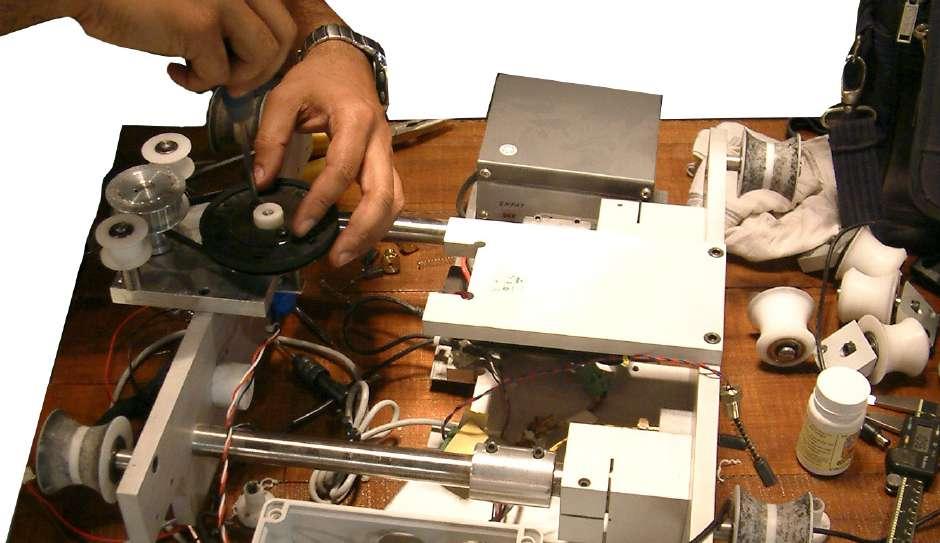
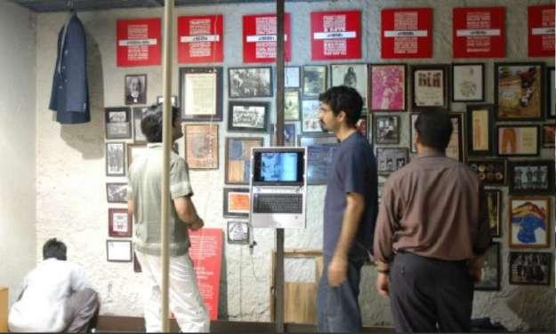
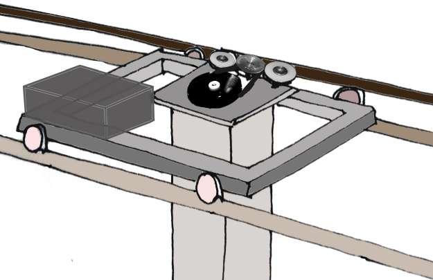
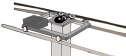
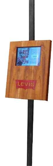
175 Branding
Fig 4.1p : controllers and actuators assembly in the history of wall
Fig 4.1q : Sketch showing the mechanism of movement in history wall.
Fig 4.1r: checking the frst testing of interactive history wall.
Fig 4.1s: sketch showing the interaction of user with interactive system of Levi’s history wall
Two guiding rollers
PLC
Pully attached with guiding roller to trace the movement for electronic input.
Pair of two guiding roller taking the load of whole assemply with movement.
4.http://studiolotus.in/levis-rivet/
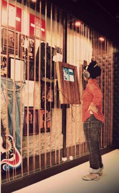
Further in the Revit store certain small elements add in the interaction of customers with the retail experience as well as interactive user experience. Like for instance the ‘vintage’ clothing is suspended in glass cubes coated with a polarizing flm that looks completely transparent while looking at the product, but seems to mist over when one walks away from it. The ‘Current’ product range, inspired by construction workers, sits on stacked polycarbonate roofng sheets. Copper-clad saddle forms scattered throughout act as multifunctional stands that can be used for everything, from seating, to putting down the clothes the customer does not want to buy after he or she comes out from the ftting room. The entire stock (about a thousand jeans not on display) is stored in slotted angle shelving behind a wall of full-height sliding panels of raw denim stretched on mild steel frames. Such an innovative display ideas together with interactive walls attract customers as well as challenge the usual retail interior designing. 4
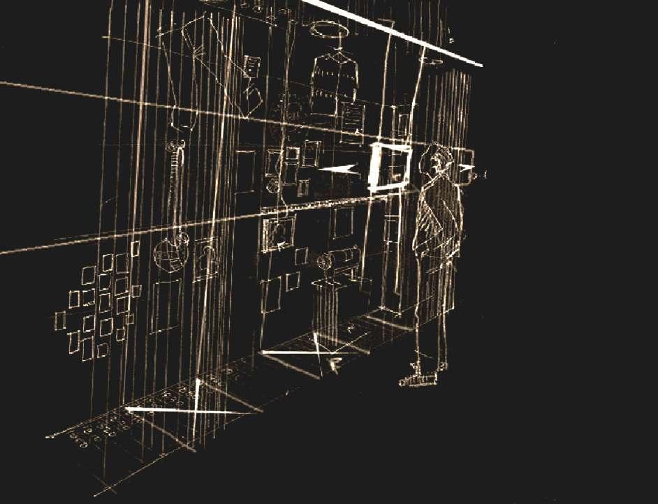
176
Memorablia
Imagery transfered onto concrete slabs Sound tubes 3D
YEAR
a decade LCD
Scrolling LCD panel allows you browse the year zone for detail Copper screen
10’6” Visible wall height HISTORY WALL 30”
reproduction
Objects
ZONES Each zones covers
panel
Fig 4.1t: User or customer interacting with the interactive wall of levi’s histroy.
Fig 4.1u: Sketch and details about the interactive history wall of levi’s.
These kinds of interaction in the retail space improve the impact of brand on the customers and globally on the brand identity.
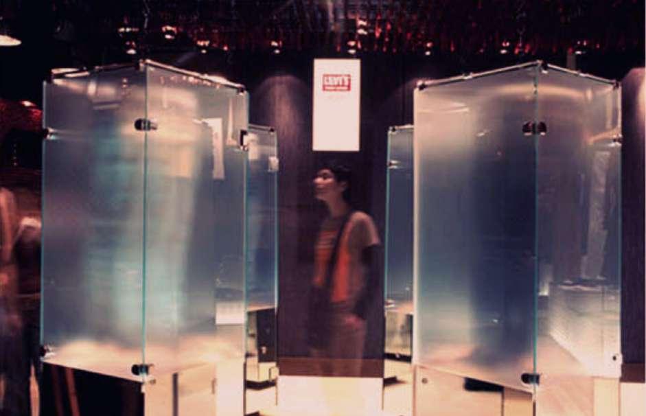
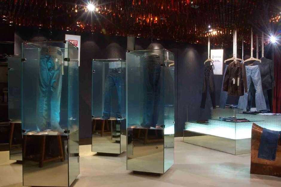
177 Branding
Fig 4.1v: Polarized glass cube becomes transparent when customers coming closer.
Fig 4.1w: Ploarized glass cube becomes translucent when customers walks away.
Case Study 4.2: Kinetic Installation - BMW Museum
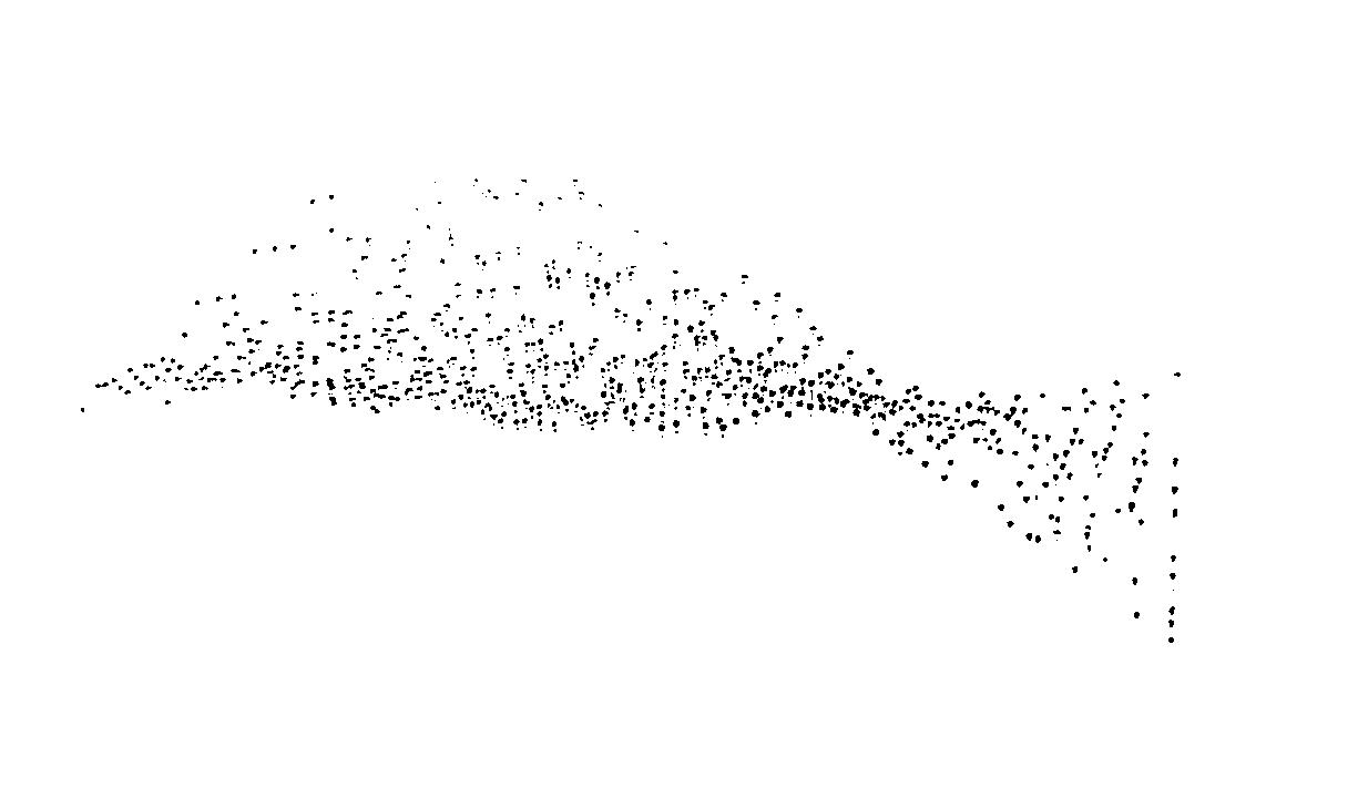

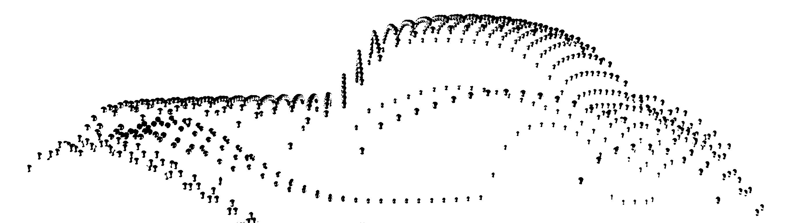
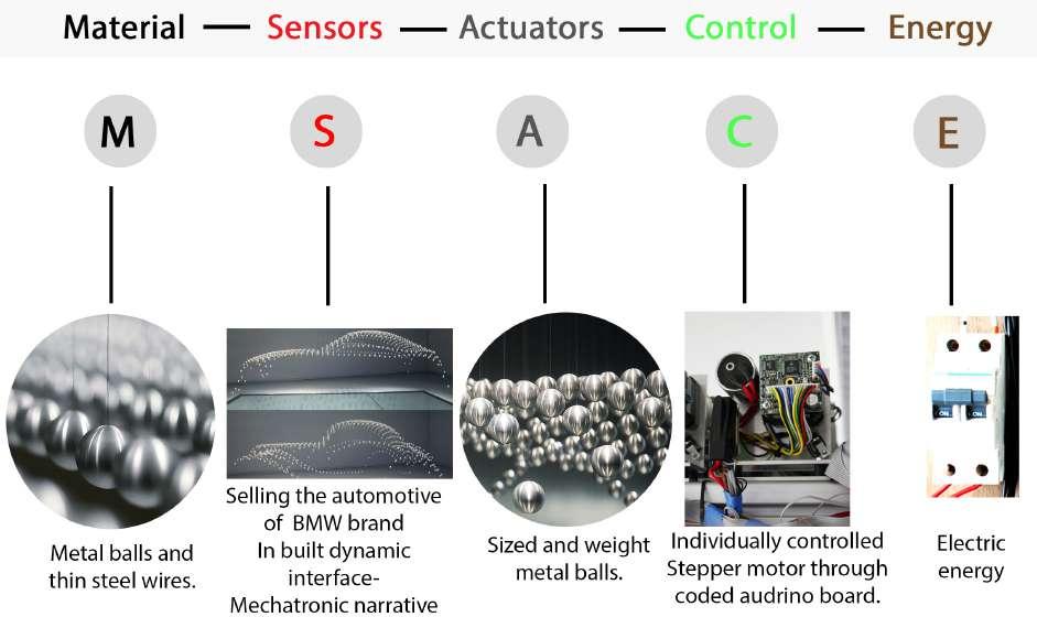
178
Fig 4.2 a: Elements used in interactive system.
Fig 4.2 b: Interactive kinetic ball sculpture of BMW Museum, Munich: A form fnding process of BMW cars.
Branding
INTERACTIVE KINETIC INSTALLATION: The thematic installation of form fnding process in car design with audiovisual efects.
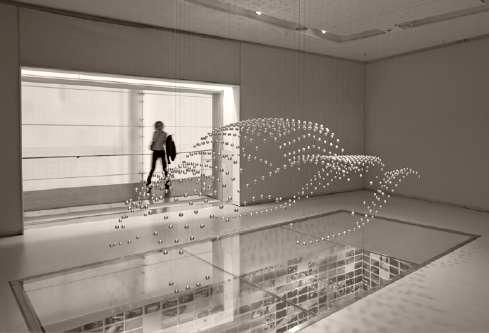
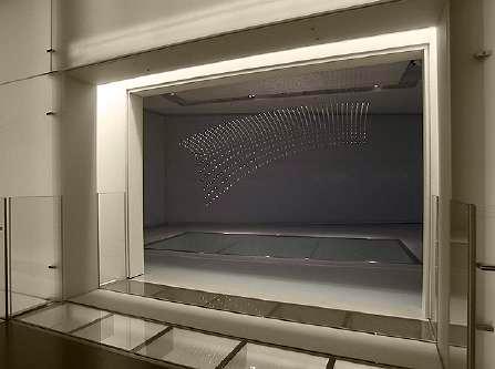
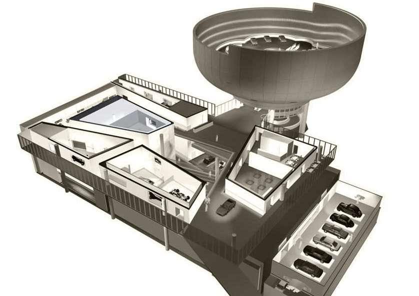
[Fig 4.2a]
The Interactive Kinetic installation for the BMW Museum in 2008, illustrates the form-fnding process in car design by translating it metaphorically into an interactive system. Fig 4.2 b,c,d]
179
Fig 4.2 c: Placement of interactive installation in museum.
Fig 4.2 d: Views showing the outside to inside space of installation at the museum, in the absence of the user the sculpture runs in an hibernation mode and infront of user installation starts its 7 minutes of choreography to attaract more gathering.
Interactive kinetic ball sculpture
This system consists of 714 metal spheres suspended from the ceiling on thin steel wires and animated with the help of mechanics, electronics and code. The up and down actuation in aluminium spheres connected with steel wires are individually controlled through stepper motors according to the coding. [Fig 4.2f,g,h]
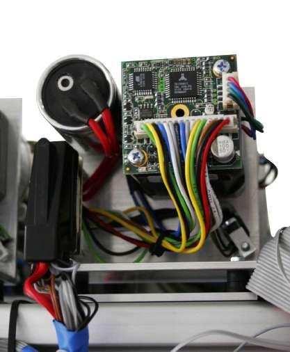
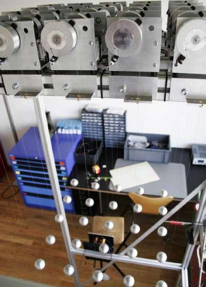
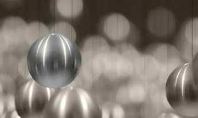
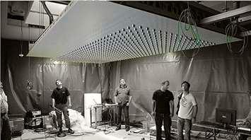
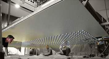
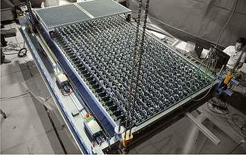
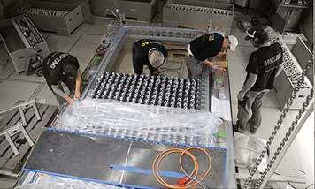
180
Fig 4.2 e: Aluminium spheres
Fig 4.2 f: Assembling actuators and controls with the choreographed logic.
Fig 4.2 g: A single motor is controlled through individual logic controllers, connected to one source - a coding interface.
A. All the actuators and controllers fxing on site
B. Installation complete with the fxixng of elements
C. Testing of the movement in actuators.
D. lifting up the installation and fxing it to the site
Fig 4.2 h: Each motor is attached to the single aluminium metal ball through thin metal wire.
Branding
The interplay of actuators, controllers and coding is performed in 7 minutes choreography. At the beginning the installation is in a chaotic state. No form or design idea has yet been found. The spheres move individually creating an impression of a spatial white noise. Slowly the frst abstract forms emerge, loosely relating to the later contours of the vehicle. In the following choreography, the succession of competing forms intersects with each other, one displaying the next. Out of this the fnal shape of the vehicle then emerges. This narrative is repeated, covering the design process of fve iconic cars from the company’s past and present. 1 [Fig 4.2i,l]
E. Each
form is the form fnding design process of Five iconic BMW cars like this one is BMW- Concept Mille Miglia
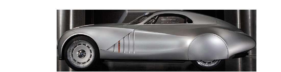
1.http://artcom.de/en/project/kinetic-sculpture/
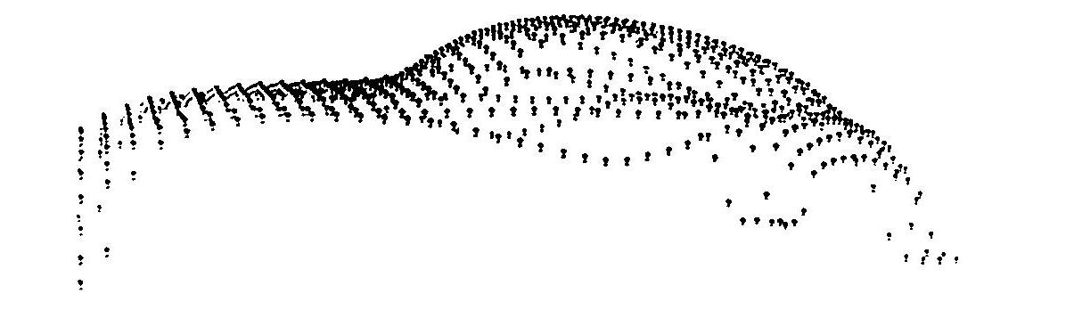
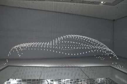
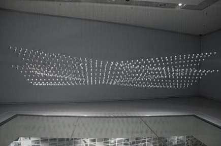
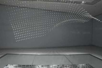
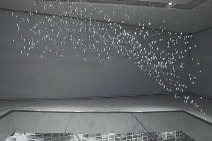
181
Fig 4.2 i: The form fnding in one iconic model of BMW and with the rest four models completes the full choreography of the interactive kinetic installation.
emerged
A. Spheres are in a chaotic state.
B. Spheres relating to the contours of the vehicle.
C. Spheres creating forms to further intersect and fnding out the fnal form of the BMW car model .
STAGE 1 STAGE 2 STAGE 4 STAGE 3
D. Spheres fnally emerges in the fnal form of the vehicle. .
ART+COM Studio, Berlin and the technicians from MKT, Munich, designed the interactive kinetic installation in a 6 sqm large feld of interior space at museum . A light strip on the surrounding walls with audiovisual efects complements the interactive kinetic installation itself, impressing with its amazing function and aesthetic form.2 [Fig 4.2j,k]
The process of form fnding becomes a visually fascinating approach and at the same time it conveys, how the “open” and “playful” creates a quality of unique elegance and sportiness.3
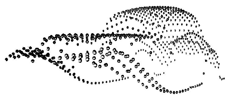
Each wall is covered with LED strip and translucent grey color material adding visual efect to the kinetic installation. Each wall shows fve words in English as well as in German language, related to the brand, which helps in improving brand identity, and overall interaction of spectators with the interactive kinetic system in interior. This kinectic sculpture can be view from the one foor down through glass slab below the sculpture which also act as an invitation for the user in the interactive interior space
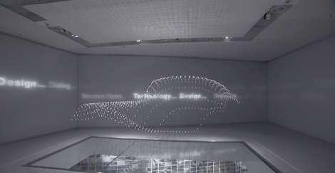
Fig 4.2 k: Image showing the combination of interior walls , visual efects and the interactive kinetic system.
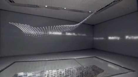
2.http://www.mkt-ag.de/en/exhibit/bmw-museum-2008.
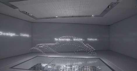
3. http://en.red-dot.org/3413.html

182
A. Visual efects at Stage 1
B. Visual efects at Stage 2
C. Visual efects at Stage 3
D. Visual efects at Stage 4
Fig 4.2 j: Visual efects changing at every stage to enhance the choreography and impact of brand on the spectators.
INNOVATION TECHNOLOGY DESIG Y FUTURE TRADITION JOY
Branding
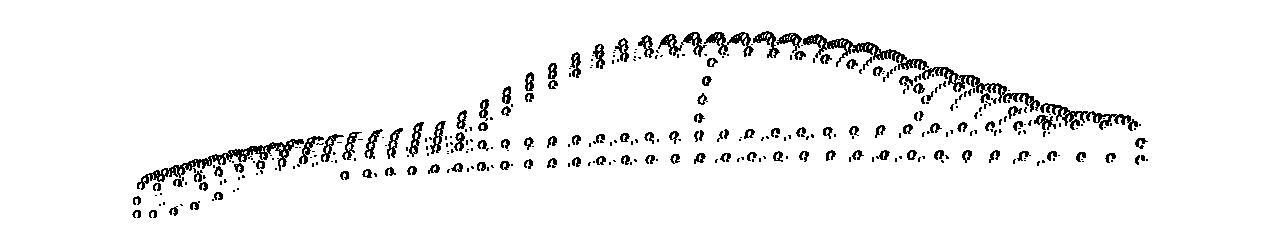
Through out the 90-year history of BMW cars the whole choreography in installation moves in a cycle of classic and contemporary shapes of car like BMW 327, BMW 1500, BMW Z4, BMW concept coupe and Mille Miglia, showing a strong identity of the brand BMW. Which further gives the strong impact of brand image on the customers, users as well as spectators. [Fig 4.2i,l]

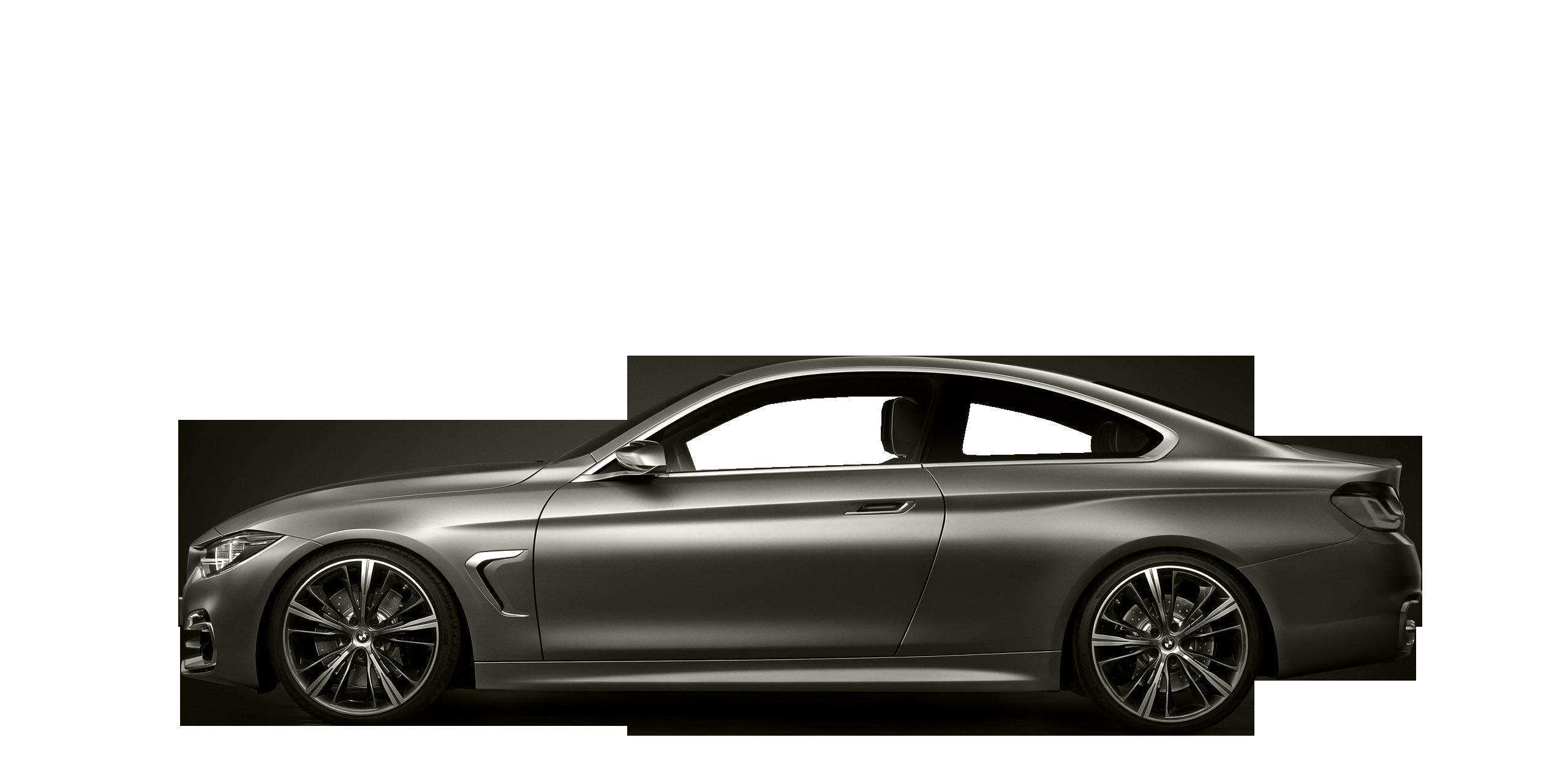
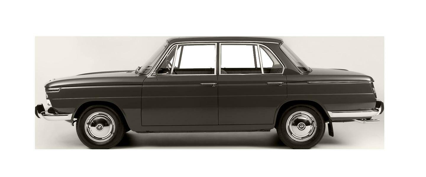
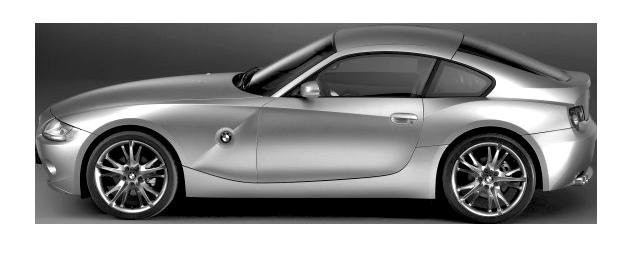
183
Fig 4.2 l: Four iconic BMW car modles used in choreography of the kinetic installation.
C. BMW Z4 Model.
B. BMW 1500 Classic Model.
A. BMW 327 Classic Model.
D. BMW Z4 Concept Coupe Model
INFERENCE :
E A C
INTERACTIVE BRANDING
INTERACTIVE SYSTEM
BRANDING
Fig 4.10 : Diagram representing the interactive branding enhancing the brands identity and brand image

184
In both the case studies, an interactive system improves the brand image as well as brand identity through visual as well as kinetic interaction of the installation with the customers. Like in the frst case study of LEVI’S store, the tactile interaction of the customers with the Rivet wall results, customer dabbling and creating diferent patterns and knowing more about the material used in the brand. The interactive wall of LEVI’S history creates, awareness and trust in the customers. But all together the display units like polarized glass cubes enhance the interactive nature of the interior space to the customer, creating a strong experience and value of the brand. Hence which improves the brands identity and image as a whole. S TACTILITY PUSH OR PULL USER OR CUSTOMER
Fig 4.9 : Interaction at Levi’s Store Museum
The second case study, the kinetic movement of the metal balls and the logic, which is seven minutes choreography of form fnding design process representing fve iconic classical and modern car models of BMW, with audio and visual efect created by the led strips. Such interaction of customers, users or spectators in the interior of the space with the kinetics, audio and visual narratives about the brand creates an impression of brand image and improves the impact of the brand identity as well as overall branding of the BMW.
S E A C DYNAMISM
CHOREOGRAPHED LOGIC OR CODING USER OR CUSTOMER
INTERACTIVE SYSTEM
Hence with the help of users act of sensing, mechanical actuators, electronic controllers and energy, such impactful interaction forw users, customers or spectators is possible with the branding at the interior spaces. These interactive systems enhance the brand image as well as brand identity from the interior space of the built form to diferent kinds of users or customers – from creating an interactive platform for the mass communication between people creating the worldwide impact of branding and brand value for any brand.
185 Branding
Fig 4.11 : Interaction at BMW Museum
186

187 Conclusion
USER LIGHT MICROCLIMATE BRANDING
CONCLUSION
CONTROL
INTERACTIVE SYSTEM
ACTUATORS
SENSORS
USER AND BUILT ENVIRONMENT
188
Fig 1.1 : A Diagram Shows The Relation Between Users And Their Environment In An Interactive System
Conclusion
According to the oxford dictionary the term interactive means; allowing a two-way fow of information between a computer and a computer-user; responding to a user’s input.1
Another defnition involves the communication or collaboration of people or things; allowing or involving the exchange of information or instructions between a person and a machine, such as a computer or a television. 2
According to the interior spaces and architecture the term interactive involves the user. It achieves this by using special sensing, actuation, computer controlling technology to react or respond to people behaviors and motions. When a building or a part of interior is called interactive it means that it integrates, or is, a system which detects, and reacts to, human behavior or external parameters. Interactive interiors would be ideal when the interior spaces could change according to users’ needs over time. Interactivity is a communication process in which each message is related to the previous messages exchanged, and to the relation of those messages to the message preceding them.3
Interactive systems in interior spaces explore emerging practices within interior or architecture and wider disciplinary felds that forge digital technologies and virtual spaces with tangible and physical spatial experiences. Instead of defning a fxed interior architectural product, an interactive interior element is in constant fux, best suited often to prototyping and semi-permanent installations.4
Interactive interiors in general is responsive to its inhabitants and environment via a feedback loop of communications, creating a two way dialogue between the users and their built environment through sensing, actuating, control and energy, generating new actions and design solutions through using a system or an interface which permits interaction [Fig: 1.1]. Essentially, it is a building or an interior spaces that reacts to its surroundings, explores sensors, actuation, controllers and virtual spaces, and is “alive” insofar as it can sense, interact, fuctuate, adapt, and learn, changing depending on users’ needs. Taking in the felds of interior or architecture, design, computer programming, and engineering, it is a mix disciplines that constructs adaptive environments for a hybrid media society.
1.On –line oxford dictionary. http://oxforddictionaries.com
2. “V2” Vocabulary Building Dictionary. http://vocabulary- vocabulary.com/dictionary/interactive.php
3. Magdalena Garbarczyk. “Does interactive architecture have a style?” Literature and media 2006, p.4
4. Kevin Holmes. Creativity Bytes: A Brief Guide to Interactive Architecture., 2011, p.2
189
INTERACTIVE SYSTEM
M S A C E
MATERIAL
USER

BRANDING

INTERIOR ELEMENT
SENSORS ACTUATORS MANIFESATION

LIGHT
INTERIOR FACADE
Unferling Fern
Interactive Wall
Adaptive Fritting

Homeostatic Screen
Tessellate
CONTROLS ENERGY
MICRO CLIMATE
EXTERIOR FACADE
ARCHITECTURE ELEMENT
Interactive Roof & Field
Glass Disk
BMW Museum
Levi’s Revit Store Museum
Thermo Bimetallic Screen
Strata
Permea
Interactive Safe House
Triangular Shades
190
Fig 1.2 : Interactive Systems From Interior Space To Architecture
Conclusion
In all the previous chapters we have studied about how an interactive system in interior spaces can change the human experience as well as behavior, through material, sensors, actuators, control and energy. These application of interactive system changes the dynamism as well as character of space- to open- semi open- semi enclosed- to enclosed, responding to the behavior and seeking attention of the user in the interior space, making interior spaces more functionally dynamic.
We have also seen that how these application of an interactive system controls the light as well as microclimate in the interior spaces of building making suitable to user or human throughout the day and further changing the nature of interior spaces more user friendly and responsive to the user needs.
These have been possible with such complex mechanisms, which modulates through sensing the user and environmental factors, or some times through the given logics and hence changes the mundane static interior spaces to responsive dynamic interiors. Interaction of;
Such interaction of users or humans with the help of multiple sensors- complex mechanical actuation- computer controllers with the material technology and energy, in interior spaces increases the efciency of the user in the interior and increases the interactive user-friendly nature of interior space with the users.
Like wise in study of unfurling fern, the response to user’s interaction is sent back in real time the user bond with the space is increased; the space starts to work at the user’s biological and psychological level of cognition. ‘Interactivity is necessary to give intelligence to this process so that the feedback loop that occurs does not become predictable, but instead grows in complexity as your experience of the space does,’5 which we have understood thoroughly in the study of interactive wall.
Lets see the comparative analysis of all the studies which includes material - sensors - actutaion - control - energy to result in perticular kind of interaction:
5. Christina Ann Rangel. “Interactivity in Architecture,” Faculty of Architecture, TU Delft, Netherlands.2007, p.3
191
CASE STUDY MATERIAL SENSORS ACTUATORS
UNFERLING FERN Plastic packets and plyester fabric
INTERACTIVE WALL
Stretchable fabric, aluminium frames
ADAPTIVE FRITTING Fritted plastic sheet pannel in metal frame
Infrared proximity sensors
Ultra sound motion sensors
Motion , light and temperature sensors
TESSELLATE Stainless steel jali Photo voltic sensors
Plastic sheets
Electric motor piston cylinder and aluminium frame
Fritted screen pannel and Stepper motor linear actuator
Tessellated screen pannels and stepper motor linear actuator
STRATA Steel metal slats Thermal, light and temperature sensors
PERMEA Aluminium and steel Thermal, light, wind and temperature sensors
BIMETALLIC SCREEN
HOMEOSTATIC SCREEN
TRIANGULAR SHADES
GLASS DISC SHADES
Thermo bimetal screen
Silver dielectric elastomer
Stretchable PTFE pannel with metal actuator
Sand blasted translucent glass disc
INTERACTIVE SAFE HOUSE
Mineral wool, steel truss and aluminium
RETRACTABLE ROOF AND FIELD
LEVI’S RIVET STORE MUSEUM
KINETIC SCULPTURE
BMW MUSEUM
Birdair fabric
Thermo bimetal
Silver electrodes
Thermal, light, temperature and wind
Thermal, light and temperature
Thermal, light, temperature, wind and humid sensors
Motion, proximity, humidity control, climate, thermal and temperature sensors
Series of pivoted slats and stepper motor
Series of pivoted slats and stepper motor
Coil shaped bimetal
Dielectric elastomers
Triangular shades and metsl linear actuator
Pivoted glass disc with vertical rod and rotational movement motor with gears
Hinged motor for windows, sliding walls, roll down gate and drawn bridge
Motorised roof and feld, motor based cable driven and linear based system
Rivet buttons and copper rods
Metal ball and thin steel wire
Interactive touch screen and push or pull pressure
Dynamic interface
mechatronic narrative
Copper rivet rod and electronic book touch pod
Sized and weight metal balls attached with stepper motors
192
Conclusion
CONTROL
PLC, Solenoid valve, MCB
Arduino complex computational logic
Arduino complex computational logic
Arduino complex computational logic
Arduino complex computational logic
Arduino complex computational logic
Heat of sunlight
Solar energy
Computer controlled (parametric) logic
Computer controlled motor with parametric data
Electronic remote device and PLC with computer
Computer controlled roof and manual button touch feld
Pull and push on copper rods and manual sliding trolley
Coded arduino board controlling stepper motor
ENERGY INTERACTION
Compressed air and electric power
User responsive
SINGLE OR MULTIPLE LOOP
Single loop
Electric power User responsive
Multiple loop
Electric power Light responsive
Single loop
Electric power Light responsive
Single loop
Electric power Light and heat responsive
Electric power Light and wind responsive
Solar energy Heat responsive
Solar energy Heat responsive
Electric power and thermal solar pannel
Electric power and photo voltic cell on disc
Solar pannel and electric power and hybrid heat system.
Light, heat and wind responsive
Light and heat responsive
Light, user, heat and wind responsive
Electric power Light, user, heat, climate and wind responsive
Electric power and manual push or pull
User and brand responsive
Electric power User and brand responsive
Single loop
Single loop
Single loop
Single loop
Single loop
Single loop
Multiple loop
Multiple loop
Single loop
Single loop
193
In both the cases of user interaction, the unfurling fern and the interactive wall and the studies where interactive system controls the light as well as microclimate in the interior of the building, maintaining user suitable environment through diferent kinds of sensory inputs and controlled complex actuations, in such a way the interior spaces can be addressed at the level where the interior elements and the space becomes dynamic, acting and reacting in response to environmental and user-specifc needs. such level of interaction can also give emphasis on dynamizm of branding in commercial spaces, hence can embrance the quality of branding - improving brand image and identity.
Interactive interiors are a total integration of the disciplines of interactive systems and interior space & architecture. It is built upon the convergence of embedded sensors including intelligence of computational and a physical component of actuation or kinetics that satisfes changes to control and adapt. The combination of these two areas will allow an environment to have the ability to reconfgure itself and automate physical change to respond, react, adapt, and be interactive.6
Interactive interiors & architecture aims at achieving more than buildings and built spaces, which are capable of simple responsive adaptations and spatial customizations, through interactive systems. Interactive systems creates spaces which are active in nature, that guides the users behavior by having the ability to reason and learn, leading to the creation of spaces which are able to maintain a dialogue with their users, not only responding to their demands, but proactively engaging themselves in all kinds of featured spatial activities.7
1.3
: Single - Loop Interactive System
194
6. Michael A. Fox. “Interactive Architecture Will Change Everything,” 2010. p.6
COGNITION
User input Output logic input Fig
7. Tomasz Jaskiewicz . “Dynamic Design Matter[s]. Practical considerations for interactive architecture, ” TU Delft, the Netherlands. 2008. p.5 Input Output U1 U2 U1
S U1 U1,U2 U1 U1,U2
E A Single Loop Interaction
C
Conclusion
The concept of applying Interactive systems can be categorized into two main levels according to their ability of response to the requirements of their surrounding environments:
Single-loop interaction; where the system had already determined particular outputs for particular inputs [Fig. 1.3]. It is reactive in nature, single- loop devices satisfy functional goals, like having building management systems that seek to optimize sunlight distribution or thermostats that regulate internal temperature. Such systems satisfy very particular efciency criteria that are determined during, and limited by, the design process.8
Multiple-loop interactive systems; which is much more difcult to achieve than the frst level, as a certain action triggered provokes its environment or user to interact so the outcome afects the frst trigger itself, giving another outcome causing another cycle of outputs and inputs in continuous cycles [Fig. 1.4]. Multiple-loop interaction does not depend upon complexity; it depends upon the openness and continuation of cycles of response. It also depends on the ability of the interacting systems, to have access to, and to modify, each other’s goals.
195
8. Usman Haque. “Architecture, interaction, systems. ” 2006. P.2 5
COGNITION C Single User input Multiple User input Output Output logic input logic input Fig 1.4
Interactive
Input Output U1 U2 X1 X2 U1a U1b U1 U2X2 , U1X1 (U2X2 , U1X1)1a , (U2X2 , U1X1)1b (Un+1Xn+1 , U n Xn)na , (Un+1Xn+1 , U n Xn)nb U1a,U1b Multiple - Loop Interaction Input Loop 1 Loop 2 Interaction goes on till n times creating multiple - loops............
S E A
: Multiple Loop
System
However, for the occupants of a building to have the sensation of a contributing to the organization of a building, the most stimulating and potentially productive situation would be a system in which people build up their spaces through “conversations” with the environment, where the history of interactions builds new possibilities for sharing goals and sharing outcomes. In such interactive interior & architectural systems, inhabitants themselves would be able to determine efciency criteria.
Understanding from such a research i have made a working prototype of interior facade which opens and closes through sensing external light condition around the building.
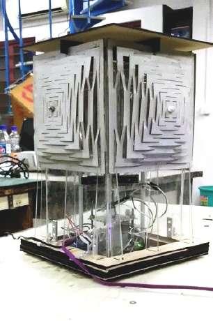
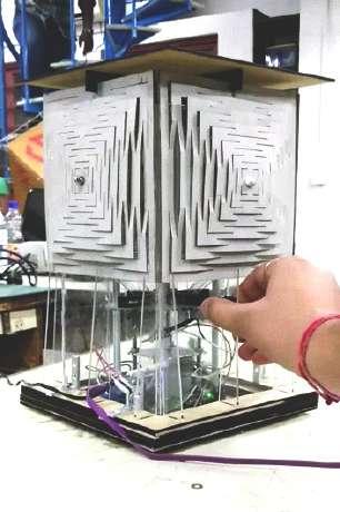
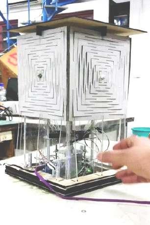
196
Semi Opened State
Open to fully Opened
Closed to
Semi
Closed state to Opened state
REFERENCES

197
References
Bibliography:
BOOKS:
1. The Eyes Of The Skin : Architecture and the Senses by Juhani Pallasmaa, 2005.
2. An architecture of the seven senses by Juhani Pallasmaa, 2012.
3. Form Follows Nature, edited by Rudolf Finsterwalder,sept 21,2011.
4. Biomimicry: An analysis of contemporary biomimetic approaches by Ramaswamy Sakthivel. Ahmedabad: SID Research Cell, CEPT University, 2007.
5. Fibre Composite Adaptive Systems By Sakthivel Ramaswamy, M. Mingallon, K. karatzas, 2010.
6. Morpho-ecologies – edited by Michael Hensel and Achim Menges, Architectural Association, 2006.
7. Versatility and Vicissitude Performance in Morpho-Ecological Design - Guest-edited by Michael Hensel and Achim Menges ,Architectural Design March/April 2008.
8. Charles Darwin and The Origin of Species -Keith A. Francis , 2007.
9. On the origin of species by means of natural selection or the preservation of favored races in the struggle for life by Charles Darwin, M.A, 1859.
10. The Alan Review ,Winter 2004.
11. General System Theory By Ludwig Von Bertalanfy, Revised Edition,1973
12. The Laws of Emotion by Nico Frijda, August 1, 2006.
13. The Evolution of Designs -Biological analogy in architecture and the applied arts ,A revised edition by Philip Steadman, 28 May 2008.
14. On Growth and Form : Organic Architecture and Beyond ,Edited by Philip Beesley & Sarah Bonnemaison, 2008.
15. MOVE: Architecture in Motion - Dynamic Components and Elements by Oliver Schaefer, Michael-Marcus Vogt, 2010.
16. Interactive architecture by Michael Fox, Miles Kemp, 16-Sep-2009.
17. Driven Architecture, Modulating Territories, Penetrating Boundaries by MarkDavid Hosale and Chris Kievid , Footprint Delft Architecture Theory Journal, Issue 06 , Spring 2010.
18. Elastic Systems For Compliant Shading Enclosures. Dynamic Façade Systems With Innovative Textile Materials By Chiara Gregoris, University IUAV of Venice - colour, environment, interactive media,Screen City-International Academic Journal, 01/2013.
19. Rethinking the Human in Technology Driven Architecture -Transactions on Architectural Education No 55 -Editors Maria Voyatzaki Constantin Spiridonidis, 2012.
198
References
20. Atmospheres: architectural environments, surrounding objects by Peter zumthor, 2006.
21. Thinking architecture BY Peter zumthor, 1998.
22. Adaptive Architecture - proceedings of the 33rd Annual Conference of the Association for Computer Aided Design in Architecture -Edited by Philip Beesley, Omar Khan, Michael Stacey, ACADIA 2013.
23. Designing Architectural Morphing Skins with Elastic Modular Systems -Chin Koi Khoo, Flora Salim and Jane Burry - international journal of architectural computing issue 04, volume 09.
24. Designing Kinetics for Architectural Facades -State change -Jules Moloney -2011.
UNPUBLISHED THESIS:
25. Programme : Morphosis -Master Thesis Explanatory Document by Tess Anna Fenwick
I.D: 1306078 ,Master of architecture ,Unitec Institute of Technology,2011.
26. Calculated Design: The role of mathematical principles in defning form, Ashwini Ashokkumar, UI 0306, CEPT University, Undergraduate Thesis, 2013.
27. Flexible Architecture For The Dynamic Societies Refection on a Journey from the 20th Century into the Future, Larissa Acharya KVI-3900, Master’s thesis in Art History Faculty of Humanities, Social Sciences and Education University of Tromsø, Spring 2013.
28. RA: Responsive Architecture – Can Architecture become more sustainable through the technological Advancements of Kinetic and Responsive Structures and skin?, AC3.1 Critical Study, Jack Webber Ford- 33276057, LEEDS School of Architecture.
29. Transience and the fexible habitat : an enquiry into systems, transient times and the fexible habitat antitype, Anjalika bose, TH-0134.
30. Interactive Architecture through Kinetic systems & Computation by Vrahimis Moutiris, Professional Diploma in Architecture, University of Nicosia Architecture Research Center January 2011.
31. The Use of Interactive Applications in the Design of Public Buildings By Dina Soliman Baghdady ,for the degree of Master of Science Degree in Architecture ,Ain Shams University, 2006.
32. Developing intelligent and adaptive building systems for our digital ecology by kai Hansen, Master of Science in architecture, Illinois institute of technology, july 2013.
33. Dynamic Shading: An Analysis by Siva Ram Edupuganti ,Master of Science in Architecture,University of Washington 2013.
34. Characteristics of dielectric elastomers and fabrication of dielectric elastomer actuators for artifcial muscle applications by William Lai - Iowa State University Ames, Iowa 2011, graduate thesis and dessertations.
199
RESEARCH PAPERS :
35. A Morphological Analysis Of The Design Space Of Input Devices -By Stuart K. Card, Jock D. Mackinlay, And George G. Robertson Xerox Palo Alto Research Center.
36. Towards a Phenomenology of Responsive Architecture: Intelligent Technologies and Their Infuence on the Experience of Space, by Mag. arch. Daniel Grünkranz Master of Architecture, PhD Student at the University of Applied Arts, Vienna.
37. Living Architecture Bytom Bender ,Chapter For Bringing Buildings To Life , July 2007.
38. Exploring The Applications Of Bio-Eco Architecture For Sustainable Design And Construction Process By M. M. Naguib And M. A. M. Hanaf,- European Journal Of Sustainable Development, 2013 , Issn: 2239-5938.
39. Beyond Open System Models Of Organization By Louis R Pondy University Of Illinois At Urbana, Ian I. Mitrof, University Of Pittsburgh, 1979.
40. Roof Structures In Motion : On Retractable And Deployable Roof Structures Enabling Quick Construction Or Adaption To External Excitations By Noémi Friedman, György Farkas.
41. Development Of Adaptive Roof Structure By Variable Geometry Truss By Kohei Kurita, Fumihiro Inoue, Noriyuki Furuya, Takashi Shiokawa, And Michihiro Natori, Technical Research Institute Of Obayashi Corporation, Japan, Institute Of Space And Astronomical Science, Japan, 2001.
42. Emotionspheres: A New Design For Human-Friendly Uavs By N. Gaissert1, R. Mugrauer, G. Mugrauer, A. Jebens, K. Jebens, C. Rabe, And E.m. Knubben Bionic Learning Network, Festo Ag & Co. Kg, Ruiter Strasse 82, 73734 Esslingen, Germany, 2014.
43. Shape morphing wind-responsive facade systems realized with smart materials by Lorenzo Lignarolo, Charlotte Lelieveld, Patrick Teufel , Delft University of Technology, Delft, The Netherlands, 2013.
44. ROBOTIC ENVIRONMENTS by Henriette Bier, Department of Architecture, Delft University of Technology, Delft, The Netherlands, 2011.
45. IFC based BIM or parametric design? by J.C. Hubers, Delft University of Technology, The Netherlands, 2003
46. Interactive Environments: A multi-disciplinary approach towards developing real-time performative spaces by Nimish Biloria ,Hyperbody, Faculty of Architecture, TU Delft, Julianalaan 134 2628 BL Delft, The Netherlands, 2011.
47. Interactive Space: Searching For A Dual Physical - Virtual World By Hafzur Rahaman, Beng-Kiang Tan ,Department Of Architecture School Of Design And Environment National University Of Singapore, 2008.
200
References
48. Bioinspiration For Engineering And Architecture Materials—Structures—Function by George Jeronimidis , centre for biomimetics university of reading university, reading, uK, 2007.
49. Materializing a responsive interior: designing minimum energy structure based on dielectric elastomers by Aurélie Mossé, MA Textile Futures, PhD Candidate, Centre for IT & Architecture Guggi Kofod, PhD, Institute of Physics and Astronomy, ACMP Mette Ramsgaard Thomsen, Professor, Head of Centre for IT & Architecture Royal Danish Academy of Fine Arts, School of Architecture, Philip de Langes allé 10, 1435 , Copenhagen, Denmark , 2011.
50. Construction of Smart Building Skins with Flow and Bend Split Products by Stefan Schäfer, Ante Ljubas, Scholeh Abedini, Chair of Constructive Design and Building Construction, Technical University of Darmstadt, Petersenstraße 12, 64287 Darmstadt, Germany, 2013.
Illustration Credits:
INTRODUCTION :
Fig. A: Edited by self.
Fig. B: http://image.slidesharecdn.com/biogeochemicalcyclesandconservationecolo gy2010edition-111122133319-phpapp02/95/biogeochemical-cycles-and-conserva tion-ecology-2010-edition-12-728.jpg?cb=1321970400.
Fig. C: http://4.bp.blogspot.com/-KefLmKuHTp8/VNzY7MyQNtI/AAAAAAAAHxw/-Isc_ Ev8a-8/s1600/butter fy_lifecycle1.jpg
Fig. D: http://i.ytimg.com/vi/heOSw7HGcR4/maxresdefault.jpg
Fig. E: http://allpicts.in/wp-content/uploads/2015/05/Nature-Wallpaper-HD-withHoopoeBird-Feeding-baby-in-nest.jpg
Fig. F: http://ben.biomimicry.net/wp-content/uploads/2012/12/Indian_Harvester_Ant_ Nest_.jpg
Fig. G: http://www.redrockrvpark.com/blog/uploaded_images/SunfowerLittleBack_ 093825-751915.jpg
Fig. H: https://abouquetfrommendel.fles.wordpress.com/2012/08/mimosa-pudica -wapk-jpg.jpg?w=584
Fig. I: http://thumbs.dreamstime.com/t/laps-et-temps-r%C3%A9el-de-temps-%C3% A9troits-du-lotus-jaune-rose-44754423.jpg ; https://mmbiz.qlogo.cn/mmbiz/WCJp7
hXkLrULibiao9TWhCfLMguHIl7FphjZRodI7vktTUX0ylnlHJ0aKwE7qV6vCqiasticlCX5b
KE1SqeeP7Hk1w/0?wx_fmt=jpeg ; edited by self
201
Fig. J: http://usercontent1.hubimg.com/7061010.jpg
Fig. K: Fibre Composite Adaptive System by Sakthivel Ramaswamy, M.Mingallon, K. Karatzas, pg 31
Fig. L: Fibre Composite Adaptive System by Sakthivel Ramaswamy, M.Mingallon, K. Karatzas, pg 34
Fig. M: http://ehp.niehs.nih.gov/wp-content/uploads/2013/01/ehp.121-a18.g004.png
Fig. N: http://ehp.niehs.nih.gov/wp-content/uploads/2013/01/ehp.121-a18.g004.png
Fig. O: http://ehp.niehs.nih.gov/wp-content/uploads/2013/01/ehp.121-a18.g004.png
Fig. P: https://www.youtube.com/watch?v=5iqP1oPZ3Qw; cropped from video
Fig. Q: http://www.adaptivebuildings.com/abu-dhabi-airport.html; cropped from video
Fig. R: http://www.castillenti.it/images/1948ce23-d37c-473c-b226-0f61b122126e.jpg
a. http://www.knippershelbig.com/sites/default/fles/styles/projekt1494/public/ image_project//12572-picture.jpg?itok=4WX3STyV
b. https://lh3.googleusercontent.com/uzKssRsHKzhq_J9XWPjlwh1U3-fvhySNJUFT 6MhoaC-V9G78DoP6FT-slnlekOCJbzn42Q=s126
c. https://lh3.googleusercontent.com/XrXssV-p6yXu6San1Z8mwlSaYMW7JE8g 7z1Ud9gVlD2M-zkz0YGQgtFqiV9j1g92ft15=s127
USER :
Fig. 1.1: Edited by self
Fig 1.2: https://www.youtube.com/watch?v=PVz2LIxrdKc
CASE STUDY 1.1 :
Fig. 1.1a: edited by self
Fig. 1.1b: edited by self
Fig. 1.1c: edited by self
Fig. 1.1d: https://farm3.staticfickr.com/2532/3933487278_5841354eb7_b.jpg
Fig. 1.1e: edited by self
Fig. 1.1f: edited by self
Fig. 1.1g: edited by self
Fig. 1.1h: edited by self
Fig. 1.1i: edited by self
Fig. 1.1j: edited by self
Fig. 1.1k: edited by self
Fig. 1.1l: edited by self
Fig. 1.1m: edited by self
Fig. 1.1n: edited by self
202
References
Fig. 1.1o: edited by self
Fig. 1.1p: edited by self
Fig. 1.1q: edited by self
Fig. 1.1r: edited by self
Fig. 1.1s: edited by self
Fig. 1.1t: edited by self
CASE STUDY 1.2 :
Fig. 1.2a: edited by self
Fig. 1.2b: edited by self
Fig. 1.2c: https://lh3.googleusercontent.com/ypYU2NdCuAXXVumT3-MfxO4MG1u-UukS wRtrTH-0ABw0BaBQqAvzgLw8ULgNhMSV4ajVlw=s127
Fig. 1.2d: https://lh3.googleusercontent.com/ioQ6Uj2VrozLZlmrl1wNc2c-iwu7F6lN74krAD Cy4jx4oCoPcOsP0fNzlzQ9IShBhsixQDg=s128
Fig. 1.2e: edited by self
Fig. 1.2f: fle:///C:/Users/Dell/Downloads/FP6-Hosale-Kievid.pdf pg 59
Fig. 1.2g: http://www.bk.tudelft.nl/fleadmin/Faculteit/BK/Actueel/Nieuws/Nieuwsbericht en_2010/img/overview-1392-768.jpg
Fig. 1.2h: http://storage.sur fngbird.ru/s/14/2/12/15/r2_f-0W6A101_orig_d0d2952a.jpg ; http://img5.lapunk.hu/tarhely/caesarom/galeria/826457.jpg
Fig. 1.2i: http://www.supernaturalcafe.it/wp-content/uploads/2015/09/sincronicita. jpg ; https://upload.wikimedia.org/wikipedia/commons/d/d6/Fugle,_%C3%B8r ns%C3%B8_073.jpg
Fig. 1.2j: http://www.nytimes.com/imagepages/2007/11/12/science/20071113_SWARM_ GRAPHIC.html
Fig. 1.2k: edited by self
Fig. 1.2l: edited by self
Fig. 1.2m: fle:///C:/Users/Dell/Downloads/FP6-Hosale-Kievid.pdf pg 57
Fig. 1.2n1: fle:///C:/Users/Dell/Downloads/FP6-Hosale-Kievid.pdf pg 57
Fig. 1.2n: fle:///C:/Users/Dell/Downloads/FP6-Hosale-Kievid.pdf pg 61
Fig. 1.2o: fle:///C:/Users/Dell/Downloads/FP6-Hosale-Kievid.pdf pg 59
Fig. 1.2p: fle:///C:/Users/Dell/Downloads/FP6-Hosale-Kievid.pdf pg 57
Fig. 1.2q: fle:///C:/Users/Dell/Downloads/FP6-Hosale-Kievid.pdf pg 59
Fig. 1.2r: fle:///C:/Users/Dell/Downloads/FP6-Hosale-Kievid.pdf pg 59
Fig. 1.2s: edited by self
Fig. 1.2t: edited by self
Fig. 1.2u: http://www.fubiz.net/wp-content/uploads/2009/04/interwall-3-550x416.jpg
203
Fig. 1.2v: http://www.fubiz.net/wp-content/uploads/2009/04/interwall-3-550x416.jpg; (http://deliveryimages.acm.org/10.1145/1350000/1349041/fgs/f3.jpg)
Fig.1.2w: http://archtctr2.0.viernulvier.nl/sensory_enhanced_bamboostic/Sensory%20en hanced%20Bamboostic!_fles/image042.jpg
Fig. 1.2x: http://arc.cust.edu.tw/ILSDS-1/Seminar/97-1/02.pdf
Fig. 1.2y: http://archtctr2.0.viernulvier.nl/sensory_enhanced_bamboostic/Sensory%20en hanced%20Bamboostic!_fles/image060.jpg
Fig. 1.2z: http://archtctr2.0.viernulvier.nl/sensory_enhanced_bamboostic/Sensory%20en hanced%20Bamboostic!_fles/image058.jpg
INFERENCE :
Fig. 1.3: edited by self
Fig. 1.4: edited by self
Fig. 1.5: edited by self
Fig. 1.6: edited by self
Fig. 1.7: edited by self
Fig. 1.8: edited by self
Fig. 1.9: edited by self
LIGHT :
Fig 2.1: edited - http://sustainabilityworkshop.autodesk.com/sites/default/fles/ styles/400px/public/core-page-inserted-images/shades_inside.jpg
Fig 2.2: http://sustainabilityworkshop.autodesk.com/sites/default/fles/styles/400px/pub
lic/core-page-inserted-images/shades_outside.jpg
Fig 2.3: http://sustainabilityworkshop.autodesk.com/sites/default/fles/styles/400px/pub
lic/core-page-inserted-images/shades_inside.jpg
Fig 2.4: http://sustainabilityworkshop.autodesk.com/sites/default/fles/styles/600px/pub
lic/core-page-inserted-images/shading-adaptive.jpg
Fig 2.5: http://sustainabilityworkshop.autodesk.com/sites/default/fles/styles/600px/pub
lic/core-page-inserted-images/shading-adaptive.jpg
Fig 2.6: snapshot from video - https://vimeo.com/17172536
Fig 2.7: http://scgp.stonybrook.edu/wp-content/uploads/2013/01/SCGP-017_web1300x200.jpg
Fig 2.8: http://img.archiexpo.es/images_ae/photo-g/sistema-iluminacion-natural-protec cion-solar-67586-4180627.jpg
Fig 2.9: http://www.adaptivebuildings.com/images/aldarcentral10.jpg
Fig 2.10: http://3.bp.blogspot.com/-stvBLXLnAQ8/U1jku6nMPpI/AAAAAAAABb4/H4f_ u2q0bWg/s1600/homeostatic-facade.jpg
204
References
Fig 2.11: snapshot from viseo smartscreen.mp4
Fig 2.12: http://acdn.architizer.com/thumbnails-PRODUCTION/db/0b/db0b86541715 bb483d22becb2f6cdbb.jpg
Fig 2.13: http://www.arquitecturayempresa.es/sites/default/fles/content/rmit-detalle_ facahda.jpg
CASE STUDY 2.1 :
Fig 2.1a: self
Fig 2.1b: above :http://www.adaptivebuildings.com/images/estonia-frit-detail.jpg
below : http://www.adaptivebuildings.com/images/adaptivefritting1.jpg
Fig 2.1c: above : snapshot from video - https://vimeo.com/17172536
middle: snapshot from video - https://vimeo.com/17172536
below : snapshot from video - https://vimeo.com/17172536
Fig 2.1d: snapshot from video - https://vimeo.com/17172536
Fig 2.1e: http://www.adaptivebuildings.com/images/fritting-explode-small.jpg
Fig 2.1f: http://cumincad.architexturez.net/system/fles/pdf/acadia09_105.content.pdf, pg 107
Fig 2.1g: http://cumincad.architexturez.net/system/fles/pdf/acadia09_105.content.pdf, pg 106 and self edited
a- snap shot from https://www.youtube.com/watch?v=puel42LcCLo and edited
Fig 2.1h: sketchup
Fig 2.1i: sketchup
Fig 2.1j: sketchup
Fig 2.1k: sketchup
Fig 2.1l(a): http://img.archiexpo.it/images_ae/photo-g/pannello-vetro-decorativo-lamina to-67586-4178865.jpg
Fig 2.1l: http://3.bp.blogspot.com/-Zo8Z3fsTUgw/TZEqiuuIn0I/AAAAAAAABf0/xOSonly Bo-w/s1600/Untitled.png
Fig 2.1m: http://img.archiexpo.it/images_ae/photo-g/pannello-vetro-decorativo-lamina to-67586-4178849.jpg
Fig 2.1n: http://img.archiexpo.it/images_ae/photo-g/pannello-vetro-decorativo-lamina to-67586-4178845.jpg
Fig 2.1o(a): http://t3.gstatic.com/images?q=tbn:ANd9GcS3GqQQKZOCyS-gFkiVK6l
5raEAOGJr4dHl80ZrcCYeLV0OItdA
Fig 2.1o(b): screenshot from video
Fig 2.1o: https://s-media-cache-ak0.pinimg.com/236x/f2/7a/8d/f27a8d6e52fd74d4de940f
227b9ccc4b.jpg
Fig 2.1p: http://www.hoberman.com/portfolio/wyssinstitute2.jpg
Fig 2.1q: http://img.archiexpo.de/images_ae/photo-m/glas-scheibe-fassadenverklei
205
dung-tur-innenausbau-trennwandsysteme-67586-8037790.jpg
Fig 2.1r: http://img.archiexpo.com/images_ae/photo-g/facade-cladding-glass-pan el-doors-interior-fttings-partition-walls-67586-8037793.jpg
Fig 2.1s: http://www.adaptivebuildings.com/wyss-institute.html
Fig 2.1t: http://www.adaptivebuildings.com/images/estonia-frit-detail.jpg
Fig 2.1u: http://buildingindustry.org/bundles/brainforcefrontend/images/uploads/posts/ resize_298x156/images/5I/Innovations/44d395da9eb67f6915f95ddc70192a.jpg
Fig 2.1v: http://img.archiexpo.com/images_ae/photo-mg/removable-partition-metal-pro fessional-67586-8037780.jpg
Fig 2.1w: http://img.archiexpo.it/images_ae/photo-g/pannello-vetro-decorativo-lamina to-67586-4179241.jpg
Fig 2.1x: http://buildingindustry.org/bundles/brainforcefrontend/images/uploads/posts/ resize_298x156/images/5I/Innovations/44d395da9eb67f6915f95ddc70192a.jpg
CASE STUDY 2.2 :
Fig 2.2 a: self edited
Fig 2.2 a: http://scgp.stonybrook.edu/wp-content/uploads/2013/01/SCGP-017_web1300x200.jpg
Fig 2.2 b:
Fig 2.2 c: http://www.adaptivebuildings.com/images/tessellate-explode-small.jpg
Fig 2.2 d: http://www.azahner.com/images/hoberman5.jpg
Fig 2.2e: http://www.hoberman.com/images/img_abi-builtwork.jpg
Fig 2.2g(a): http://www.azahner.com/images/tessellate-unveiling.jpg
Fig 2.2 g (b): http://www.azahner.com/images/tessellate-unveiling.jpg
Fig 2.2f: http://www.ladesigntech.org/newsletter_20101206.html
Fig 2.2 i:
Fig 2.2 h:
Fig 2.2j:
Fig 2.2k: up - http://img.archiexpo.it/images_ae/photo-g/pannello-protezione-solare-vet ro-metallo-facciata-perforato-67586-4180087.jp
bottom
Fig 2.2l: up- http://www.hoberman.com/HobermanPortfolio.pdf
bottom
Fig 2.2m: snapshot from video
Fig 2.2 n: self made
Fig 2.2 o: self made
Fig 2.2 p: self made
Fig 2.2 q: sketchup
Fig 2.2 r: http://onlinelibrary.wiley.com/doi/10.1002/ad.1329/abstract
206
References
Fig 2.2 s: http://patentimages.storage.googleapis.com/US8615970B2/US0861597020131231-D00000.png
Fig 2.2 t: http://cdn.archinect.net/images/514x/xl/xlxeny33b5oiq4bf.jpg
Fig 2.2 u: sketchup
Fig 2.2v: sketchup
Fig 2.2w: sketchup
Fig 2.2x: sketchup
Fig 2.2 y: http://www.inla.cn/uploads/c/1707/065930_inla_com_cn.jpg
Fig 2.2z: http://www.hoberman.com/portfolio/simonscenter.php?projectname=Si mons+Center-
Fig 2.2 z 1: http://www.hoberman.com/portfolio/simonscenter.php?projectname=Si mons+Center
Fig 2.2z2: http://www.hoberman.com/portfolio/simonscenter.php?projectname=Si mons+Center
Fig 2.2z3: http://acdn.architizer.com/thumbnails-PRODUCTION/28/6d/286d1c 9022d7121ef9ebbe119d8ad649.jpg
Fig 2.2z 4: http://acdn.architizer.com/thumbnails-PRODUCTION/06/9f/069f879c 5ccc318d9439b76bc0b9d2f4.jpg
Fig 2.2z5: http://images.adsttc.com/media/images/55f6/deab/adbc/017f/ca00/0162/slide show/titanium-rain-screen-mock-up-panels-tesselate-range-of-motion-permitsbetween-56-and-7-daylight.jpg?1442242188
Fig 2.2z6: snapshot-Tessellate™ and ZIRA™ façade mockup for KAFD Spas https://vimeo. com/54392676
Fig 2.2z7: snapshot-Tessellate™ and ZIRA™ façade mockup for KAFD Spas https://vimeo. com/54392676
Fig 2.2z8: snapshot-Tessellate™ and ZIRA™ façade mockup for KAFD Spas https://vimeo. com/54392676
Fig 2.2z9: snapshot-Tessellate™ and ZIRA™ façade mockup for KAFD Spas https://vimeo. com/54392676
Fig 2.2z10: snapshot-Tessellate™ and ZIRA™ façade mockup for KAFD Spas https://vimeo. com/54392676
CASE STUDY 2.3 :
Fig 2.3a: http://www.adaptivebuildings.com/images/cityofustice2.jpg
Fig 2.3b: http://www.artincontro.com/wp-content/uploads/EasyRotatorStorage/user-con tent/erc_34_1436951551/content/assets/3-0.jpg
Fig 2.3c: http://www.adaptivebuildings.com/images/cityofustice2.jpg
Fig 2.3d: http://www.adaptivebuildings.com/images/strata-explode-small.jpg
207
Fig 2.3e: http://www.archicentral.com/wp-content/images/unbenannt-51.jpg
Fig 2.3f: http://www.adaptivebuildings.com/city-of-justice.html
Fig 2.3g: http://img.archiexpo.es/images_ae/photo-g/sistema-iluminacion-natural-protec cion-solar-67586-4180627.jpg
Fig 2.3h: http://www.adaptivebuildings.com/city-of-justice.html
Fig 2.3i: snapshot from video - http://www.adaptivebuildings.com/city-of-justice.html
Fig 2.3j: snapshot from video - http://www.adaptivebuildings.com/city-of-justice.html
Fig 2.3k: http://www.hoberman.com/HobermanPortfolio.pdf,pg 7
Fig 2.3l: http://catalystreview.net/wp-content/uploads/2012/08/CHUCK-HOBERMAN.jpg
Fig 2.3l1: self
Fig 2.3m: http://www.adaptivebuildings.com/adaptive-shading-esplanade.htm
Fig 2.3n: http://www.adaptivebuildings.com/adaptive-shading-esplanade.html
Fig 2.3o: http://www.hoberman.com/HobermanPortfolio.pdf,pg 16
Fig 2.3p: http://www.hoberman.com/HobermanPortfolio.pdf,pg 16
Fig 2.3q: http://www.adaptivebuildings.com/emergent-surface.html
Fig 2.3r: http://www.adaptivebuildings.com/emergent-surface.html
Fig 2.3s: http://www.adaptivebuildings.com/heliotrace.html
Fig 2.3t: http://www.adaptivebuildings.com/heliotrace.html
Fig 2.3u: http://www.adaptivebuildings.com/heliotrace.html
Fig 2.3v: http://www.adaptivebuildings.com/heliotrace.html
Fig 2.3w: http://www.adaptivebuildings.com/heliotrace.html
Fig 2.3x: http://www.adaptivebuildings.com/heliotrace.html
Fig 2.3y: http://www.dwell.com/great-idea/article/heliotrace-robotic-facade
Fig 2.3z: http://www.adaptivebuildings.com/heliotrace.html
Fig 2.3z1: http://www.adaptivebuildings.com/images/heliotrace5.jpg
http://www.hoberman.com/portfolio/heliotrace_main.jpg
CASE STUDY 2.4 :
Fig 2.4a: self
Fig 2.4b: self
Fig 2.4c: self
Fig 2.4d: http://www.adaptivebuildings.com/permea-surface.html
Fig 2.4e: http://www.adaptivebuildings.com/permea-surface.html
Fig 2.4f: http://www.adaptivebuildings.com/aldar-central-market.html
Fig 2.4g: http://www.adaptivebuildings.com/aldar-central-market.html
Fig 2.4h: http://cdn.spacescapeplanni.netdna-cdn.com/wp-content/uploads/2013/07/Al dar-Central-Market-souk-Abu-Dhabi-By-Foster-Partners-25-Nigel-Young.jpg
Fig 2.4i: http://www.adaptivebuildings.com/images/abudhabiairport1.jpg
Fig 2.4j: http://www.adaptivebuildings.com/abu-dhabi-airport.html
Fig 2.4k: http://www.adaptivebuildings.com/abu-dhabi-airport.html
208
References
Fig 2.4l: http://www.adaptivebuildings.com/abu-dhabi-airport.html
CASE STUDY 2.5 :
Fig 2.5a: self
Fig 2.5b: screenshot-https://www.youtube.com/watch?v=tfWsuJDzUNY
Fig 2.5c: http://www.globalspec.com/RefArticleImages/14C30B12BB33EFDB238326585A818CDB_07_19.gif
Fig 2.5d: https://hendristmt.fles.wordpress.com/2008/10/bimetal-temperature-gauge2.gif
Fig 2.5e: self
Fig 2.5f: self
Fig 2.5g: self
Fig 2.5h: screenshot-https://www.youtube.com/watch?v=tfWsuJDzUNY
Fig 2.5i: Edited-http://www.eyeqinsretina.com/images/retina-examination.jpg
Fig 2.5j: http://www.iaacblog.com/maa2013-2014-digital-matter-intelligent-construc tions/2014/04/bimetals/
Fig 2.5k: http://www.migueljuarezdb.com/thermatrix.html
CASE STUDY 2.6 :
Fig 2.6a self
Fig 2.6b: http://b.fastcompany.net/multisite_fles/codesign/imagecache/1280/Homeostat icFacadeSystem_lede.jpg
Fig 2.6c: http://blog.selector.com/au/fles/2011/01/HFS03.jpg
Fig 2.6d: http://media.treehugger.com/assets/images/2011/10/homeostatic-fa cade-open-closed-inside.jpg
Fig 2.6e: http://materia.nl/article/homeostatic-facade-system/
Fig 2.6f: http://materia.nl/article/homeostatic-facade-system/
Fig 2.6g: http://materia.nl/article/homeostatic-facade-system/
Fig 2.6h: https://www.youtube.com/watch?v=GEipnLf40_Y
Fig 2.6i: https://www.youtube.com/watch?v=GEipnLf40_Y
Fig 2.6j: https://arch5541.fles.wordpress.com/2012/11/300px-dielectric_elastomers2.gif
Fig 2.6k: http://cdnstatic.visualizeus.com/thumbs/70/b9/70b97f125e617f6a4a6ad50a d155a7ee_i.jpg
Fig 2.6l: https://www.youtube.com/watch?v=GEipnLf40_Y Fig 2.7a:
CASE STUDY 2.7 :
Fig 2.7b:http://solucionista.es/wp-content/uploads/al-bahar-towers-abu-dhabi-1.jpg
http://solucionista.es/wp-content/uploads/al-bahar-towers-abu-dhabi-5.jpg
Fig 2.7c: http://amkasitis.blogspot.in/2012/11/oiutoiutoiutyoiu.html
Fig 2.7d: http://amkasitis.blogspot.in/2012/11/oiutoiutoiutyoiu.html
209
Fig 2.7a: self
Fig 2.7e: http://www.designboom.com/weblog/images/images_2/danny/albahar/alba har05.jpg
http://3.bp.blogspot.com/-SXg7EqztDoE/UO8jFogDYII/AAAAAAAAAsM/_RK16JZ kT-s/s1600/new-headquarters-al-bahr-towers-abu-dhabi-uae.jpg
Fig 2.7f: http://www.ctbuh.org/LinkClick.aspx?fleticket=c8GlZooATFg%3D&tabid=3845 &language=en-US
Fig 2.7g: https://s-media-cache-ak0.pinimg.com/236x/59/13/04/591304b9ac0a3773584f3 3fb19cbcd33.jpg
Fig 2.7h: http://www.ctbuh.org/LinkClick.aspx?fleticket=c8GlZooATFg%3D&tabid=3845 &language=en-US
Fig 2.7i: http://www.architecturaldigest.com/gallery/buzzworthy-new-buildings-architec ture-slideshow#4
Fig 2.7j: https://chi-athenaeum.org/assets/international_architecture/06---Aedas_Al-BahrTowers_Image-10.png
Fig 2.7k: http://en.e4g.org/wp-content/uploads/2014/12/5384afb2c07a8044af0000bd -light-matters-mashrabiyas-translating-tradition-into-dynamic-facades-07-open ing-sequence.jpg
Fig 2.7l: http://compositesandarchitecture.com/?attachment_id=2370
Fig 2.7m: http://www.architectureadmirers.com/bahr-towers-are-the-new-magnifcentdynamic-project-in-abu-dhabi/
http://www.architectureadmirers.com/wp-content/uploads/2014/05/aedas-albahr-towers3-150x150.jpg
CASE STUDY 2.8 :
Fig 2.8a: self
Fig 2.8b: http://www.designboom.com/wp-content/uploads/2013/07/sean-godsell-archi tects-RMIT-design-hub-designboom02.jpg
Fig 2.8c: http://oi39.tinypic.com/358p2tt.jpg
Fig 2.8d: http://www.panoramio.com/photo/96280172
http://archrecord.construction.com/tech/techFeatures/2013/images/05/Dynam ic-facades-2.jpg
Fig 2.8e: Snapshot- Hub and Spokes RMIT University https://www.youtube.com/ watch?v=xDyeATq5GBY
Fig 2.8f: http://www.architectural-review.com/pictures/606x422ftpad[0]/1/7/6/1226176_ designhub.jpg
Fig 2.8g: http://flt3rs.net/sites/default/fles/case/others/RMIT%20design%20hub_14%20 copy.jpg
Fig 2.8h: http://designaddicts.com.au/platform/wp-content/uploads/2013/07/ScreenShot-2013-07-22-at-9.53.46-PM.png
210
References
Fig 2.8i: http://www.panoramio.com/photo/96280165
Fig 2.8j: Snapshot- Hub and Spokes RMIT University https://www.youtube.com/ watch?v=xDyeATq5GBY
Fig 2.8k: Self
Fig 2.8l: A. http://www.australiandesignreview.com/wp-content/uploads/2013/06/GodsellPeddle-Thorp-RMIT-Design-Hub-2.jpg
B. http://www.archdaily.com/335620/rmit-design-hub-sean-godsell/51277d32b 3fc4b55e40000aa-rmit-design-hub-sean-godsell-photo
C. http://www.seangodsell.com/rmit-design-hub
Fig 2.14: self
Fig 2.15: self
INFERENCE: MICROCLIMATE :
Fig 3.1: Edited by self
Fig 3.2: http://www.ucar.edu/communications/stafnotes/0603/images/urbanheat.jpg
Fig 3.3: http://sustainablesources.com/images/passsolar3.gif
Fig 3.4: http://ecovidainternational.com/wp-content/uploads/2015/10/Passive-solar-de sign-300x197.jpg
Fig 3.5: http://i0.wp.com/www10.aeccafe.com/blogs/arch-showcase/fles/2011/05/zokazo la_breeze_engine_hostel_diagram_human_energy_balance.jpg
Fig 3.6 : https://i.ytimg.com/vi/ajWCXdRwhDA/maxresdefault.jpg
Fig 3.7 : http://time-az.com/images/2015/02/20150202UnivPhoenixCardinals01.jpg
Fig 3.8 : Edited by self
CASE STUDY 3.1:
Fig 3.1a : self
Fig 3.1b : http://cdn.miragestudio7.com/wp-content/uploads/2011/05/zombie_architec ture_house_proof2.jpg and edited
Fig 3.1c : Edited by self
Fig 3.1d: http://www.kwkpromes.pl/dom-bezpieczny-2/2248
Fig 3.1e: https://www.youtube.com/watch?v=NerQs_SOwRo
Fig 3.1f: https://www.youtube.com/watch?v=giEfpV8hUwk/SNAP SHOT AND EDITED
Fig 3.1g: https://www.youtube.com/watch?v=giEfpV8hUwk/ SNAP SHOT AND EDITED
Fig 3.1h: Edited by self
Fig 3.1i: Edited by self
Fig 3.1j: https://www.youtube.com/watch?v=giEfpV8hUwk/ SNAP SHOT AND EDITED
Fig 3.1k: http://weburbanist.com/2011/07/17/bunkers-ours-the-safe-house-is-an-openshut-case-2/
211
Fig 3.1l: http://weburbanist.com/2011/07/17/bunkers-ours-the-safe-house-is-an-openshut-case-2/
Fig 3.1m: http://www.kwkpromes.pl/en/safe-house/2248
Fig 3.1n: http://www.kwkpromes.pl/en/safe-house/2248
Fig 3.1o: https://www.youtube.com/watch?v=giEfpV8hUwk/ SNAP SHOT AND EDITED
Fig 3.1p: https://www.youtube.com/watch?v=giEfpV8hUwk/ SNAP SHOT AND EDITED
Fig 3.1q: Edited by self
Fig 3.1r: https://www.youtube.com/watch?v=giEfpV8hUwk/ SNAP SHOT AND EDITED
Fig 3.1s: https://www.youtube.com/watch?v=giEfpV8hUwk/ SNAP SHOT AND EDITED
Fig 3.1t: https://www.youtube.com/watch?v=giEfpV8hUwk/ SNAP SHOT AND EDITED
Fig 3.1u: https://www.youtube.com/watch?v=giEfpV8hUwk/ SNAP SHOT AND EDITED
Fig 3.1v: https://www.youtube.com/watch?v=giEfpV8hUwk/ SNAP SHOT AND EDITED
Fig 3.1w: https://www.youtube.com/watch?v=giEfpV8hUwk/ SNAP SHOT AND EDITED
Fig 3.1x: https://www.youtube.com/watch?v=giEfpV8hUwk/ SNAP SHOT AND EDITED
Fig 3.1y: https://www.youtube.com/watch?v=giEfpV8hUwk/ SNAP SHOT AND EDITED
CASE STUDY 3.2:
Fig 3.2a: Edited by self
Fig 3.2b: Edited by self
Fig 3.2c: https://blog-blogmediainc.netdna-ssl.com/SportsBlogcom/fleware house/83107/09b67e8768bade0a2ea5f54ba5a05da8.jpg
Fig 3.2d: https://www.fickr.com/photos/universityofphoenix/3766934802- edited
Fig 3.2e: self edited
Fig 3.2f: fle:///C:/Users/admin/Desktop/BULBUL%20MICRO/Micro%20Climate/pheo nix%20stadium/kinetic%20architecture/University%20of%20Phoenix%20Stadi um%20-%20Projects%20-%20Birdair,%20Inc..pdf
Fig 3.2g: Edited by self
Fig 3.2h: Edited by self
Fig 3.2i: Edited by self
Fig 3.2j: http://serbinstudio.com/wp-content/uploads/2013/06/stadium_05.jpg
Fig 3.2k: Edited by self-https://visualfactorystudio.fles.wordpress.com/2011/01/universi ty-of-phoenix-tekla-model.jpg
Fig 3.2l: fle:///C:/Users/admin/Desktop/BULBUL%20MICRO/Micro%20Climate/pheo
nix%20stadium/kinetic%20architecture/University%20of%20Phoenix%20Stadi um%20-%20Projects%20-%20Birdair,%20Inc..pdf`
Fig 3.2m: http://www2.vietbao.vn/images/vn75/phong-su/75158857-115416_cardi
nals-stadium.jpg
Fig 3.2n: A. http://cdn.fansided.com/wp-content/blogs.dir/60/fles/2015/01/nf-superbowl-xlix-stadium-views.jpg
212
References
B. https://www.fickr.com/photos/universityofphoenix/3766932502.
C. http://4.bp.blogspot.com/-kB7DDg1YARA/VA5mpzT83qI/AAAAAAAAeoY/ Mr2o1gr-vK8/s1600/107.jpg
D. http://i1.wp.com/upload.wikimedia.org/wikipedia/commons/d/d9/Universi ty_of_Phoenix_Stadium_no_feld.jpg
Fig 3.2o: http://time-az.com/images/2015/02/20150202UnivPhoenixCardinals01.jpg
Fig 3.2p: Self edited
Fig 3.2q: http://www.uni-systems.com/en/solutions/components/linear-bearing#stress-re lease-systems
Fig 3.2r: http://3.bp.blogspot.com/-O7wjGIO8tuA/VLkvyZQ2TrI/AAAAAAAAqa8/5Vz
pLH1IXEw/s1600/university-of-phoenix-stadium-map.jpg
Fig 3.2s: http://3.bp.blogspot.com/-O7wjGIO8tuA/VLkvyZQ2TrI/AAAAAAAAqa8/5Vz
pLH1IXEw/s1600/university-of-phoenix-stadium-map.jpg
Fig 3.2t: http://3.bp.blogspot.com/-O7wjGIO8tuA/VLkvyZQ2TrI/AAAAAAAAqa8/5Vz
pLH1IXEw/s1600/university-of-phoenix-stadium-map.jpg
Fig 3.2u: http://www.uni-systems.com/en/solutions/components/local-control#con trol-systems
Fig 3.2v: https://i.ytimg.com/vi/EUs70OZnqpc/maxresdefault.jpg
Fig 3.2w: http://www.uni-systems.com/en/solutions/components/cable-drive#drive-sys tems
Fig 3.2x: http://www.uni-systems.com/en/solutions/components/cable-drive#drive-sys tems
Fig 3.2y: http://www.birdair.com/sites/default/fles/styles/gallery_enlarge_horiz/public/ projects/UnivPhoenixCardinals04.jpg?itok=W41UTfsi
Fig 3.2z:: http://uni-engineer.com/images/uofproof03.jpg
Fig 3.2a1: http://www.uni-systems.com/images/Components/11_1_crop.jpg
Fig 3.2a2: http://3.bp.blogspot.com/-O7wjGIO8tuA/VLkvyZQ2TrI/AAAAAAAAqa8/5Vz pLH1IXEw/s1600/university-of-phoenix-stadium-map.jpg
Fig 3.2a3: http://universityofphoenixstadium.com/downloads/Sales_Brochure.pdf, pg 13
Fig 3.2a4: http://universityofphoenixstadium.com/downloads/Sales_Brochure.pdf, pg 12
Fig 3.2a5: http://www.uni-systems.com/en/projects/featured-projects/university-of-phoe nix-stadium
Fig 3.2a6: http://universityofphoenixstadium.com/downloads/Sales_Brochure.pdf, pg 6
Fig 3.2a7: http://universityofphoenixstadium.com/downloads/Sales_Brochure.pdf, pg 12
INFERENCE:
Self edit images and diagrams
213
BRANDING:
Fig 4.1: http://www.aurion.ae/images/logo1.jpg
Fig 4.2: http://brawnycode.com/wp-content/uploads/2014/07/brand-is-experience.png
Fig 4.3: self
Fig 4.4: http://www.brainmates.com.au/wordpress/wp-content/uploads/2010/02/Figure1-Brand-Audit.JPG
Fig 4.5: http://www.aurion.ae/images/logo1.jpg
Fig 4.6: http://rrcsa.ca/wp-content/uploads/2015/10/Pepsi_logo_2014.svg_.png
http://www.mahala.co.za/wp-content/uploads/2011/09/Levis_Bw_GF_BLK_KO_CMYK.jpg
http://www.btbsport.com/wp-content/uploads/2015/08/Nike_Logo_02.jpg
http://favbulous.com/wp-content/uploads/2013/08/1017.jpg
http://img.bmw-syndikat.de/gallery/172/750/536667_bmw-syndikat_bild_nomember.jpg
Fig 4.7: self
Fig 4.8: self
CASE STUDY 4.1:
Fig 4.1a: self
Fig 4.1b: emailed from studio lotus
Fig 4.1c: emailed from studio lotus
Fig 4.1d: self
Fig 4.1e: emailed from studio lotus
Fig 4.1f: emailed from studio lotus
Fig 4.1g: emailed from studio lotus
Fig 4.1h: emailed from studio lotus
Fig 4.1i: emailed from studio lotus
Fig 4.1j: emailed from studio lotus
Fig 4.1k: emailed from studio lotus
Fig 4.1l: emailed from studio lotus
Fig 4.1m: emailed from codesign
Fig 4.1n: emailed from codesign
Fig 4.1o: emailed from codesign
Fig 4.1p: emailed from codesign
Fig 4.1q: self
Fig 4.1r: emailed from codesign
Fig 4.1s: self
Fig 4.1t: emailed from studio lotus
Fig 4.1u: emailed from studio lotus
214
References
Fig 4.1v: emailed from studio lotus
Fig 4.1w: emailed from studio lotus
CASE STUDY 4.2:
Fig 4.2a: self
Fig 4.2b: self
Fig 4.2c: http://www.e-architect.co.uk/images/jpgs/exhibitions/bmw_museum_a190510_ artcom.jpg
Fig 4.2d: http://4.bp.blogspot.com/-tm1gUrxGyA0/UbYdHH3ZAdI/AAAAAAAAQd4/Te4gm 5wP8iI/s1600/kinetik_gallery_09.jpg
http://www.joachimsauter.com/img/big188.jpg
Fig 4.2e: http://www.mkt-ag.de/sites/default/fles/styles/adaptive/public/produkte/AC_Ki netic_Close_3.png?itok=vqC8FsKB
Fig 4.2f: http://www.joachimsauter.com/img/big189.jpg
Fig 4.2g: https://artcom.de/wp-content/uploads/2014/09/MG_0125_1-440x620.jpg
Fig 4.2h: https://artcom.de/wp-content/uploads/2014/09/MG_0166_11-440x620.jpg
Fig 4.2i: self edited and snap shot from vedio-https://www.youtube.com/watch?v=HVhV ClFMg6Y
Fig 4.2j: snapshot edited from vedio - https://www.youtube.com/watch?v=-sEm1llNtmM
Fig 4.2k: self
Fig 4.2l: self edited and images from - http://www.gulum.net/arabalar/resimler/BMW_ Z4C_379-1024.jpg, http://www.7-forum.com/news/2011/bmw_1500/bmw_1500_ p90074530-c.jpg, http://f30.bimmerpost.com/forums/attachment.php?attachmen tid=795721&d=1355417833, http://myautoworld.com/BMW/histo ry/1929/327-328/1937_BMW_327_Sportkabriolett.jpg
INFERENCE:
Fig 4.9 : self
Fig 4.10 : self
Fig 4.11: self
CONCLUSION:
Fig 1.1: self
Fig 1.2: self
Fig 1.3: self
Fig 1.4: self
215
