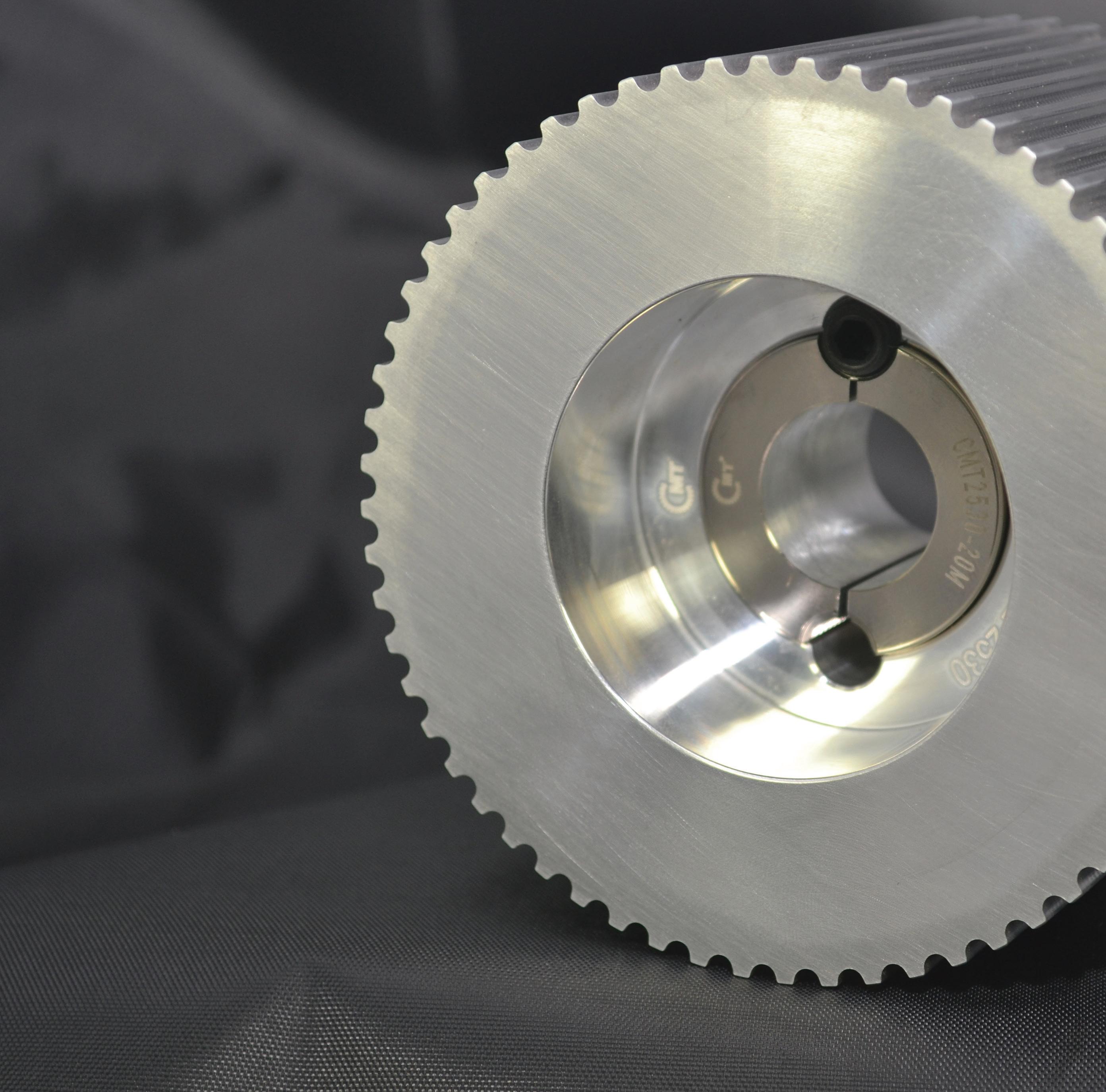
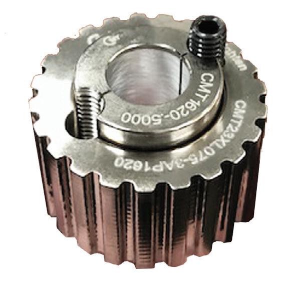
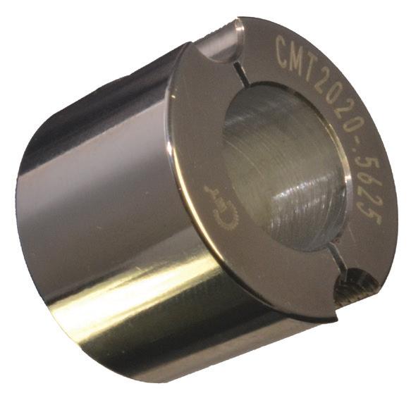
power transmission guide
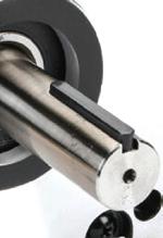
Our keyless hub-to-shaft connection
tapered shaft
Email or call to get your CMT Stock Products Catalog. Order today. Ships today!


Precise. Reliable. Trusted.


Step Up Your Game


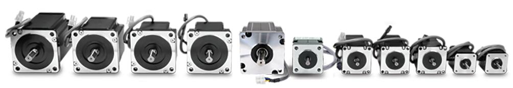
Stepper Motors, Drives, and Linear Actuators
Motors starting at: $22.50 (STP-MTR-17040)


Use our Stepper System Selector to size a stepper motor for your application, then walk through all the options for that motor; including encoders, drives, power supplies, cables, and more.
www.automationdirect.com/selectors/steppers

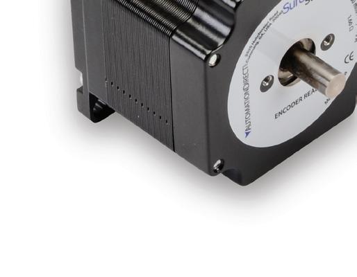
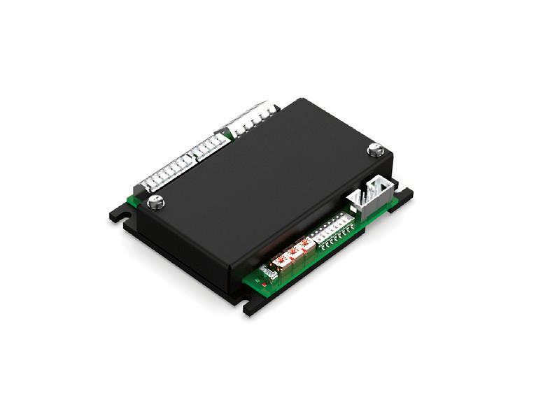
Stepping systems marry high-performance microstepping drives with high-torque stepper motors (in single- and dual-shaft models) to provide simple and accurate control of position and velocity.
The new Ever Motion Solutions Titanio series microstepping drives can monitor back-EMF signals from the motor to detect motor stalling without encoder feedback. Ever drives also use sinusoidal current control to increase efficiency and smooth the motion.
SureStep® integrated stepper motor/drives save space and lower costs. Standard and advanced models are available.
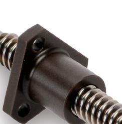
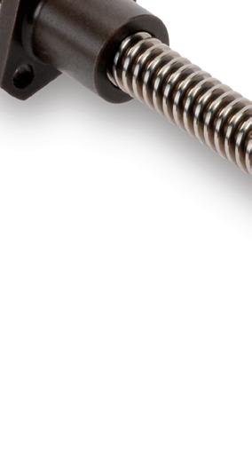
SureStep stepper motor linear actuators incorporate a lead screw as the rotor. These actuators translate precise rotational movement into linear motion. They are maintenance free and are a great cost-saving option for linear motion applications.

•
•


partner for material handling solutions
Arrowhead™
Bauer™ Gear Motor
Boston Gear™
Busse™/SJI
Grove Gear™
Kollmorgen™
Link-Belt™
McGill™
ModSort™
Perceptiv™
Rex™
Rexnord™
Sealmaster™
Stearns™
Thomson™
Valu Guide™
Warner Electric™
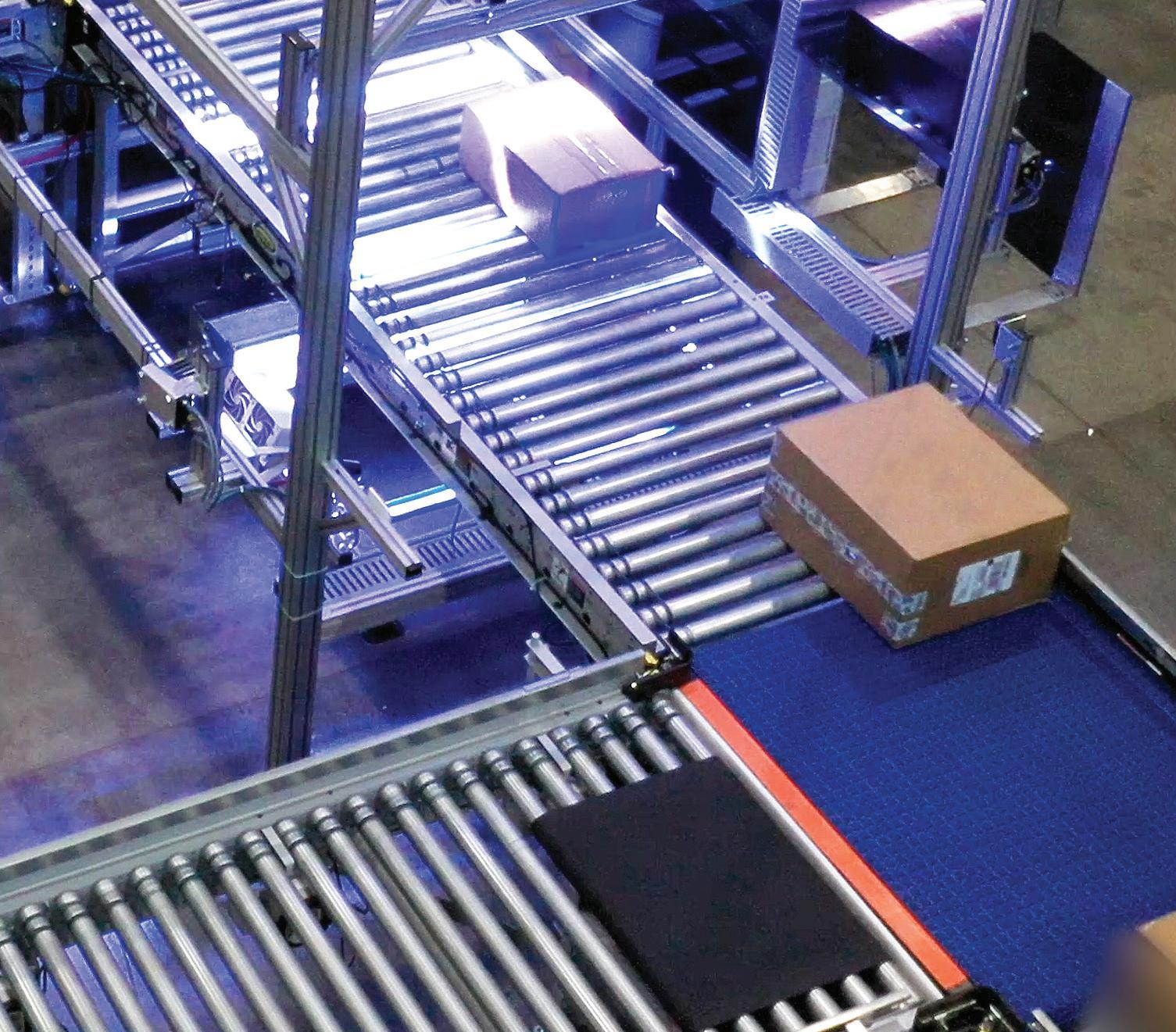
In the fast-paced world of intralogistics and material handling, efficiency and uptime are critical. Businesses need a partner that not only enhances accuracy and productivity but also prevents costly unplanned downtime.
From high performance PMAC integrated motor/drives to complete custom conveyance systems, Regal Rexnord brings together unparalleled engineering expertise and industry-leading brands to offer tailored, end-toend solutions.
Improve system efficiency, reduce operating costs, and increase product throughput with ONE Regal Rexnord solution.

Regal Rexnord, Arrowhead, Bauer Gear Motor, Boston Gear, Busse/SJI, Grove Gear, Kollmorgen, Link-Belt, McGill, ModSort, Perceptiv, Rex, Rexnord, Sealmaster, Stearns, Thomson, Valu Guide, and Warner Electric are trademarks of Regal Rexnord Corporation or one of its

REMEMBER WHAT BEAULIEU SAID ABOUT TARIFFS
In late January of this year,
I was fortunate enough to see our industry’s beloved economist Alan Beaulieu present at the A3 Business Forum in Orlando. As he’s announced his retirement, that keynote was likely the last time folks in our industry will get hear him speak.
Beaulieu will forever remain loved for his accurate economic forecasting, sardonic wit, and ability to speak to the absolute center on all things political. So, we all might heed his words on tariffs.
Back in January, about one-third of all imports into the U.S. were tariffed, and the value of those goods was climbing — though still lower than in the past.
“But … people don’t understand tariffs. They think, ‘We’ll throw some more tariffs on and that’ll protect American businesses, and everything will be hunky dory.’ That’s not how it works. It’s not how it works at all,” warned Beaulieu.
For starters, as a government revenue stream, tariffs are tiny. “The dollar amount that comes in through tariffs was $74B in fiscal 2024; the federal government spent $7.4T. So, tariffs are not going to save the economy, federal budget, or deficit. If we were to tax every import in the U.S. at 70% it would match what’s received from personal income taxes. Of course, that’s not going to happen,” said Beaulieu. Again, this was a January 2025 keynote when 70% tariffs were widely considered ludicrous.
Another issue is that of inflation. “There’s an impact of tariffs that doesn’t get talked about called inflation. Because if you make something cost more coming ashore, whoever is processing that, whoever is
using that, whoever is adding onto it as it goes through and ends up in a B2B or B2C situation … that item is going to cost more,” he said.
When the cost of goods goes up, it’s called inflation. “So the more tariffs there are, the more inflation we could get.”
Yet another problem is the prospect of retaliatory tariffs — and at least in his keynote, Beaulieu gave no indication that hard bargaining with longtime ally trade partners would give the U.S. the upper hand.
“If we were to anger Europe, if we were to anger Germany, if we were to anger any one of our major trading partners to the point where they said, ‘We’re not going to provide you with this unless you pay a steep tariff’ — like China is doing to us on some minerals and materials that we need — if they were to do that, that also increases cost,” said Beaulieu.
Domestic exports are also put at risk. “If they put enough tariffs on us, it increases the likelihood that we’ll export less. As we export less because of retaliatory tariffs, that hurts the general economy — because about 10% of our GDP is made up of exported goods and services. So, the more that we anger people, the more likely it is that we will slow down growth in the U.S. economy,” he continued.
One last point Beaulieu made was on who pays. “The tariff is not paid by China or Mexico or Canada or the Netherlands. The tariff is paid by the person in this country. It’s a domestic tax, not a foreign tax. That means that it’s coming out of profits. As it comes out of profits, it comes out of forward progress. It comes out of shareholder wealth creation. It has a negative impact. So, please don’t be thinking this is a great thing that holds promise for us. It is fraught with danger as well.”
“I’m not against them,” clarified Beaulieu. “What tariffs can do is protect some industries that are being unfairly treated because of dumping from other nations. I’m just trying to tell you … we have to be very careful with tariffs.”
Operations relying on imported machinery, components, and materials may be most affected by any new tariffs that go into effect — as will their short-term investments in advanced technologies. •
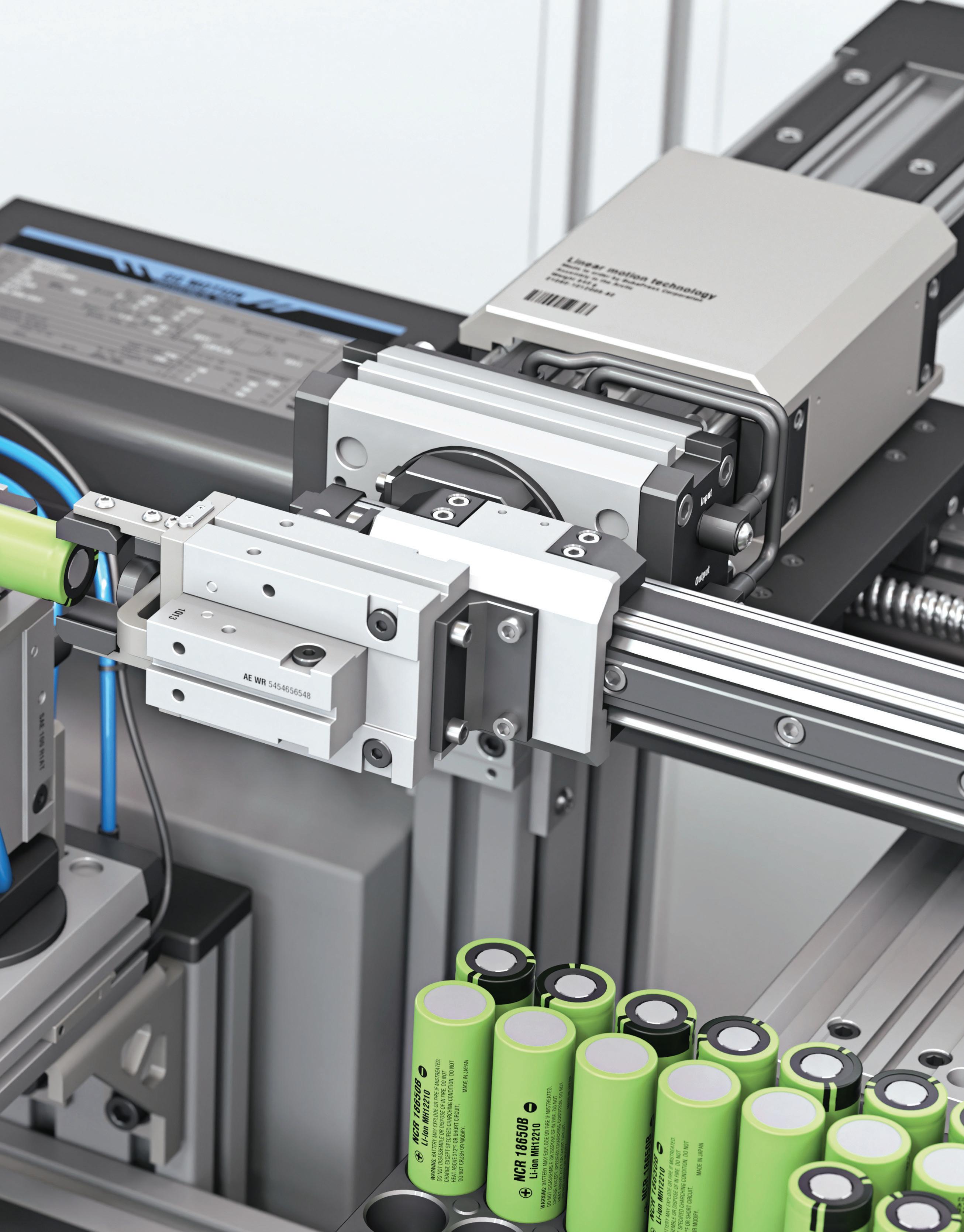
BRING ON the BRUTE FORCE LOADS
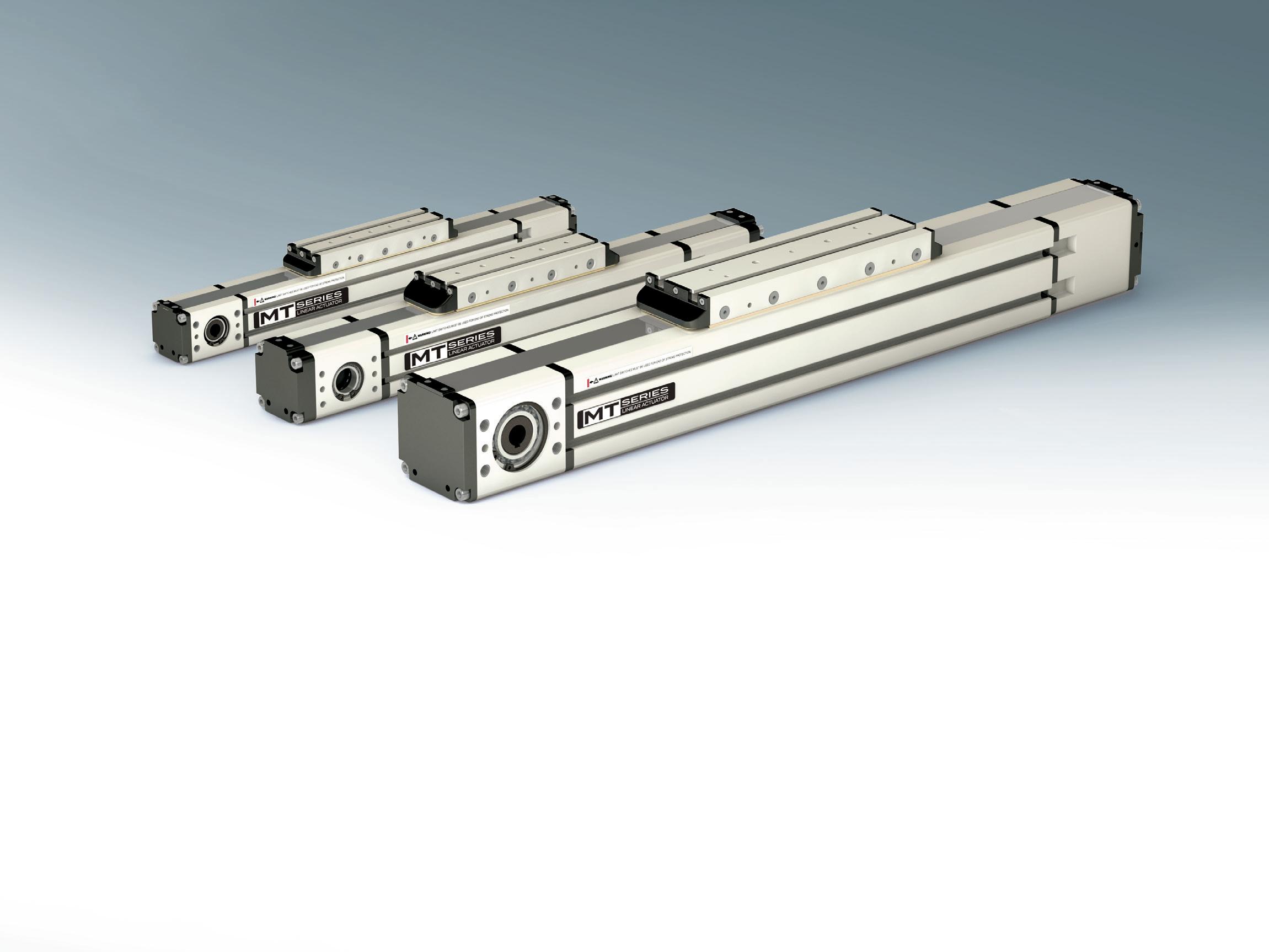
Announcing a MTB Linear Actuator Series Line Extension
The MTB Series is a belt driven, profile rail linear actuator that has a number of sizes with some design configuration availability to meet high loads and stroke length.
MTBs are fully enclosed systems that perform at speeds up to 3000 mm per/second. With the addition of the MTB 105 linear actuator, the series now can move a static load of 7500 N and with a thrust capacity of 2750 N.
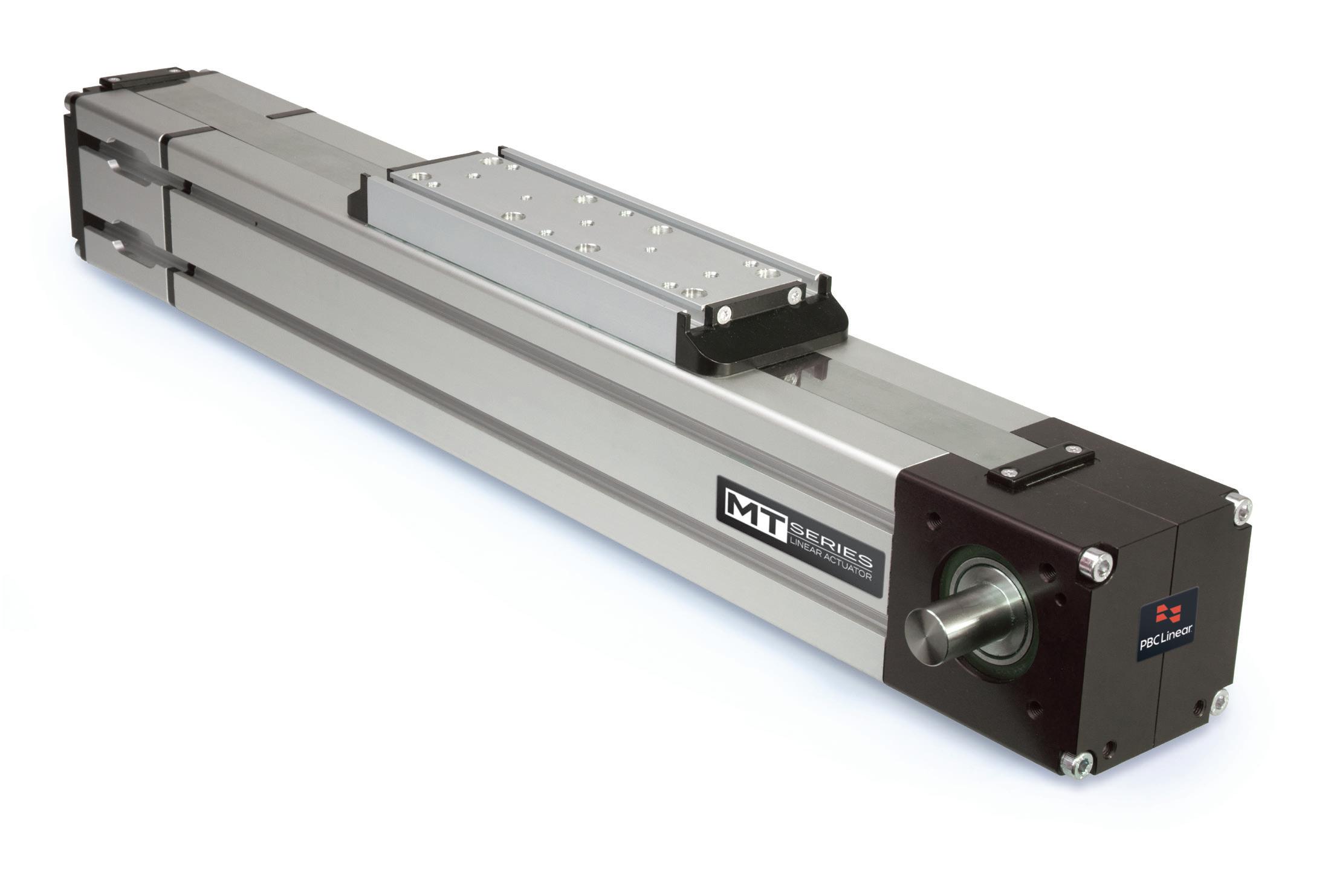
MTB 105
Applications:
Packaging and Assembly Automation
Cartesian Multi-axis Gantry Systems
Pick & Place Gantries
Automated Door Systems
Manufacturing Equipment Motion
MAX
MAX
ANALYZING AND ADDRESSING CAM-FOLLOWER SKIDDING IN ROTARY APPLICATIONS
Here, we detail what causes skidding in rotary systems. Then we compare single and double-roller cam follower designs.
BY GEORG BARTOSH PRESIDENT INTECH POWER-CORE
For production machinery with moving subsystems, wear can be a major headache. That’s especially true for those featuring traditional metal cam followers, bearings, and other mechanical elements. As we’ll explore, polymer components can be a superior alternative because they avoid metal-to-metal wear as well as grease contamination of end products.
Image: ShineBen
Consider skidding-related wear. Skidding occurs when a speed differential along contact surfaces causes metal components to slide against one another. This in turn accelerates wear-type equipment damage and can ultimately lead to unanticipated machine downtime. For many manufacturers (especially those that produce end products in bulk) even small interruptions can have big consequences—
including missed shipping dates and lost customers.
With traditional metal cam followers, the solution to skidding is heavy lubrication of contact surfaces — sometimes to the point of over-lubrication. But this creates its own challenges — including contamination caused by stray lubricant, for example. What’s more, external lubrication systems are costly,
labor-intensive to maintain, and nonsustainable.
In contrast, cam followers featuring advanced polymer elements are intrinsically self-lubricating to avoid these pitfalls. Plus, cam followers with polymer elements lend themselves to new and innovative mechanical designs.
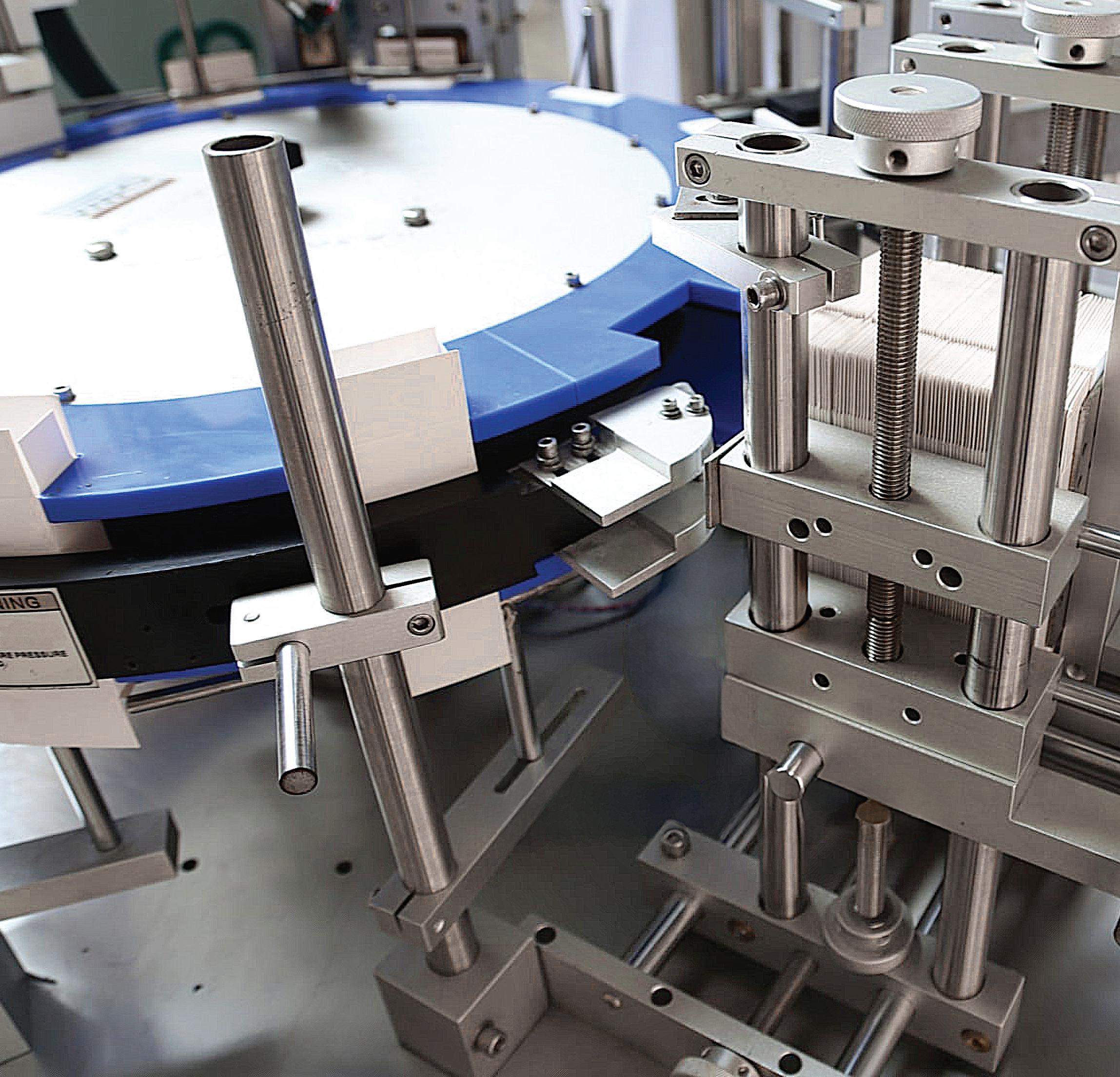
EXAMPLE APPLICATION: A PACKAGING-MACHINE TURNTABLE
Consider a packaging machine that features a large 70-in. diameter turntable to transport cardboard packages between two points. Cam followers support the rotating part of the turntable. The cam followers are mounted on a lower stationary table surface constructed of flat steel plates.
The design called for 1.75-in. diameter cam followers carrying an average load of 380 lb but lubrication was not an option. So, the manufacturer selected lubrication-free 1.75-in. metalequivalent polymeric cam followers.
At first, the manufacturer was satisfied with the turntable system’s output. But over time, friction-related temperature increases caused wear damage. More specifically, the cam followers’ surfaces became rough. The
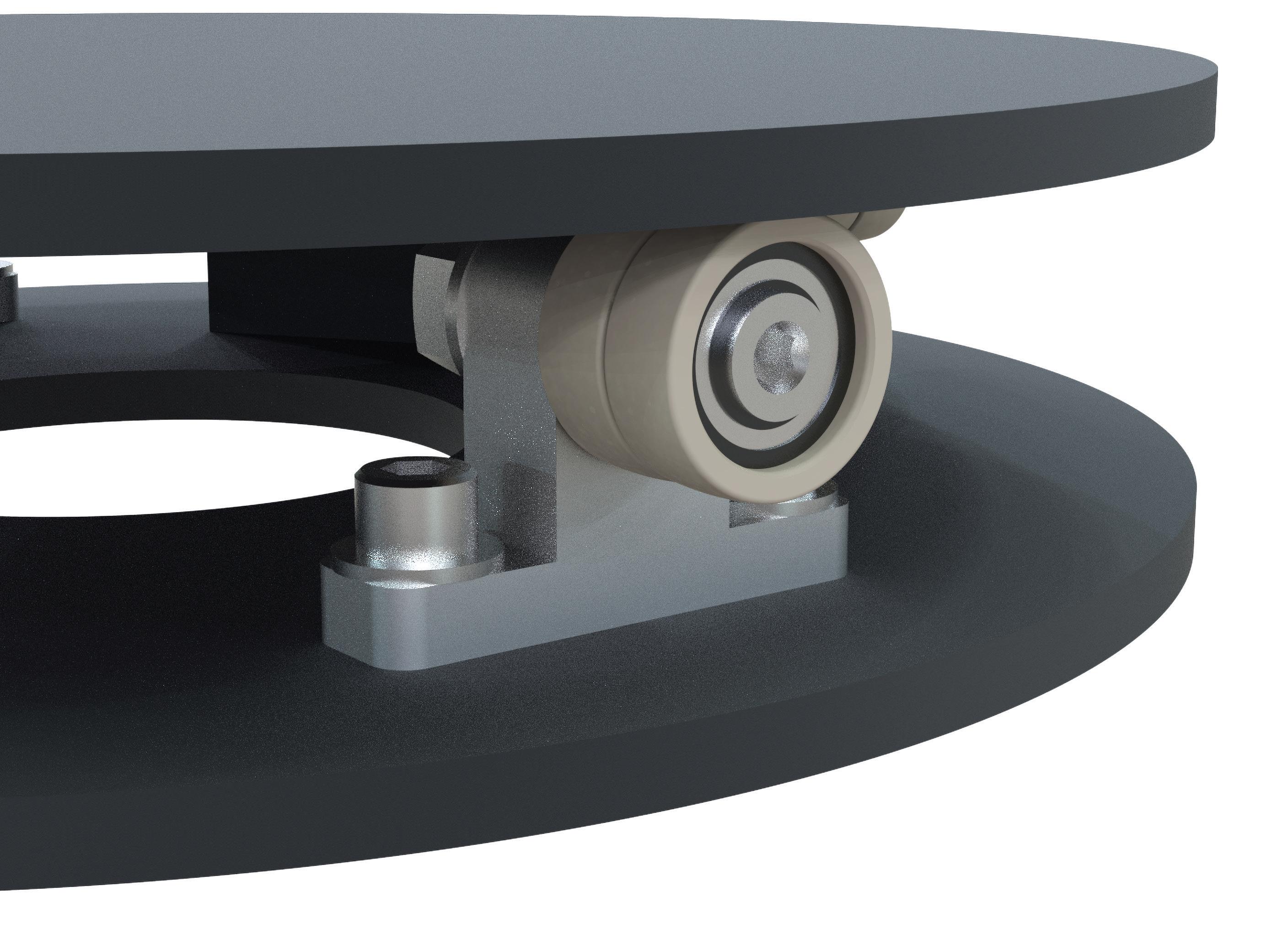
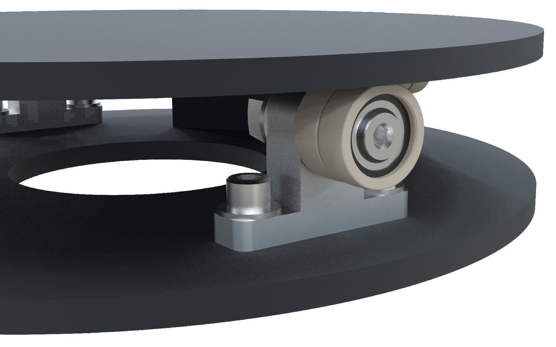
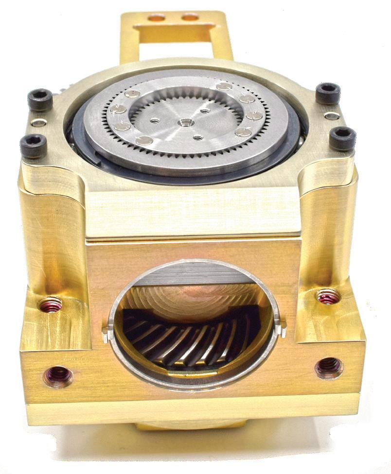
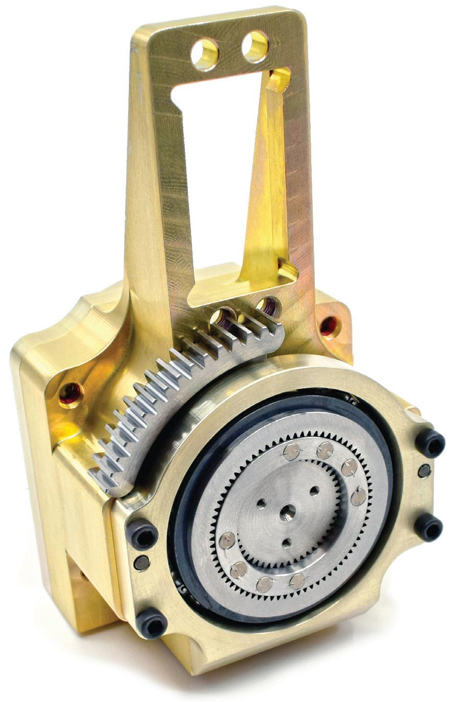
This anti-skid rotary table has a plate (top), twin INTECH iCAM cam followers on mounting brackets (middle), and a stationary support plate (bottom).
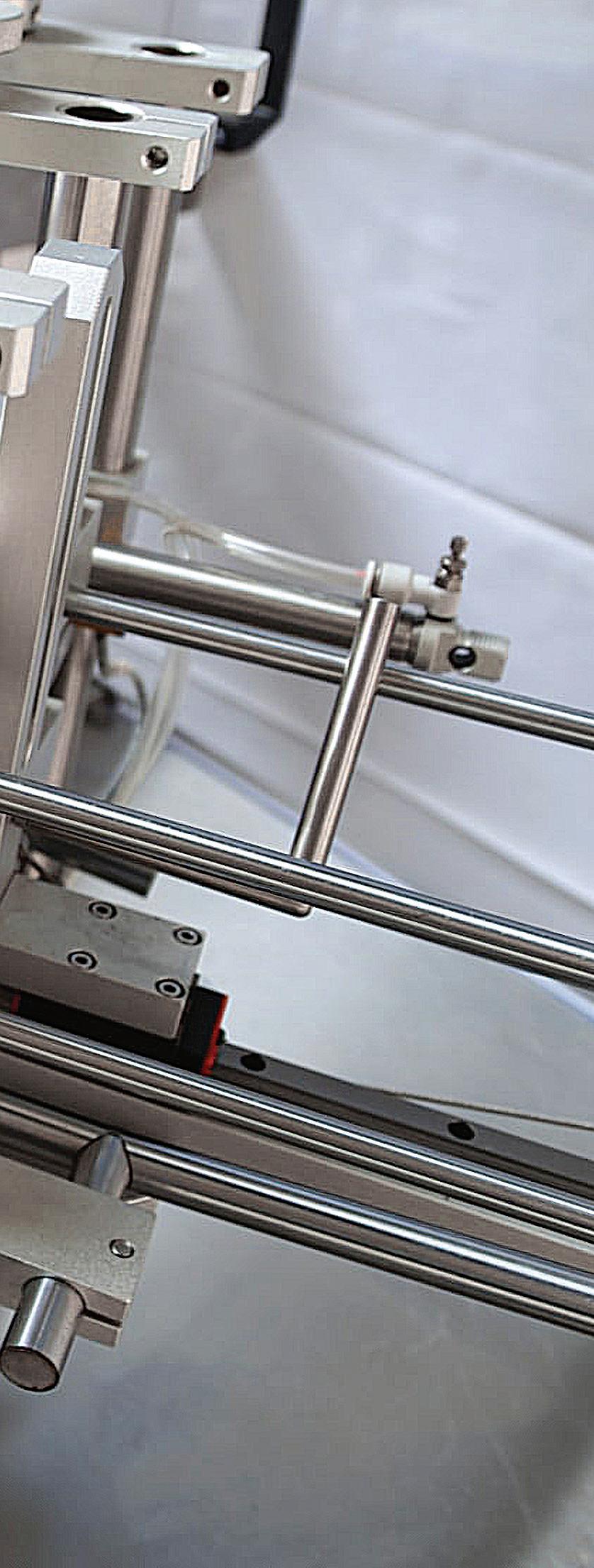
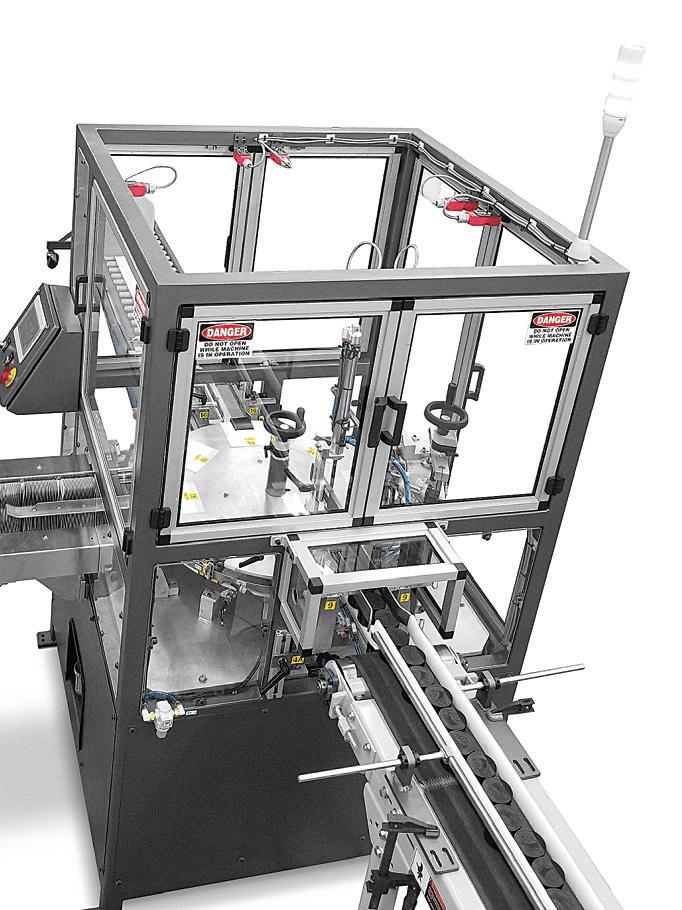
Rotary tables abound in the packaging industry. Shown here is a ShineBen vertical cartoner that uses the table for high throughput.
Shown here is a Boxxer Kartnr cartonforming machine built around a rotary table. Image: EndFlex
polymer slowly expanded, and the radial component of the friction force caused the outer racer to slip off the bearings. A new solution had to be found.
WHAT WAS THE PROBLEM?
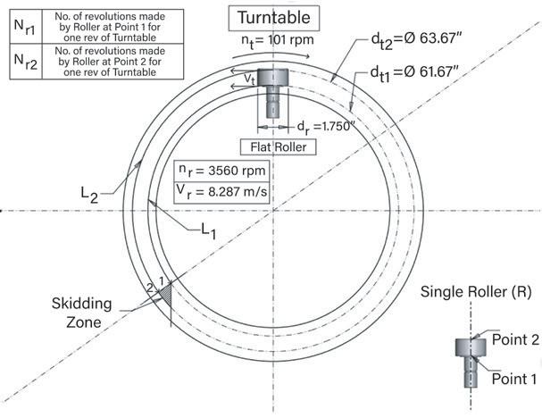
Skidding caused the damage. It occurred because the inner and outer diameters of the cam follower ran on different diameters of the turntable. This generated heat, spurred wear, and shortened the cam followers’ lifespan. Consider the figure titled Skidding zone detail. For every revolution of the turntable, Points 1 and two on the cam follower had to travel different distances. At Point 1, it traveled 193.55 in., while at Point 2, it had to travel 200.15 in. to reach the same angular position as Point 1. Because the linear velocity of all the points on the cam roller is the same, smooth turning caused the roller at Point two to travel only 193.55 in. for every turntable revolution. Skidding compensated for the rest of the distance. Eventually, the skidding — and the damage it caused — rendered the entire system inoperable, needing the manufacturer to order new parts and driving cost and valuable time. Based on the calculations, the skidding distance between Points 1 and 2 is equal to 6.6 in. Given the inner extreme of the cam roller width at Point 1, the skidding distance increases as we move toward the outer extreme at Point 2 as shown in the Skidding zone detail figure. In addition, the turntable rotates for thousands of revolutions — exponentially increasing the overall skidding distance. Such skidding leads to wear and tear due to friction, shortening the roller’s service life.
TWIN CAM-FOLLOWER DESIGN BENEFITS
Because lubricating the turntable wasn’t an option, the manufacturer needed an alternative solution to prevent the cam followers from skidding. That’s when the twin-roller design was identified as a leading suitable solution. This cam follower, which is more efficient and longlasting, incorporates two rollers mounted on the same shaft — each one fitted with a precision ball bearing and running
SKIDDING ZONE DETAIL
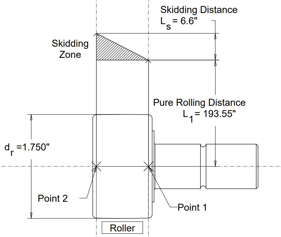
This visual representation of skidding shows how on the old design, for every revolution of the turntable, Points 1 and 2 on the cam follower had to travel different distances. Because the linear velocity of all the points on the cam roller is the same, smooth turning caused the roller at Point 2 to travel only 193.55 in. for every turntable revolution. Skidding accounted for the rest of the distance.
SINGLE-ROLLER SKIDDING
independently on the turntable.
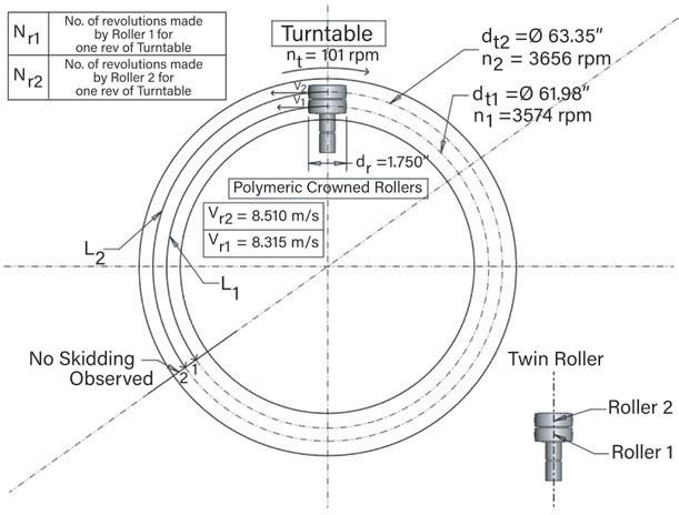
To further minimize wear, each roller also has a slight crown. This reduces the roller-turntable contact from a line of contact to a point of contact. Because both rollers can run independently with different linear velocities, they can cover different distances via pure rolling, eliminating friction resistance and skidding altogether.
As shown in calculations, all points on a single-roller cam follower must travel at the same constant speed, causing the roller to skid 6.6 in. to cover the needed distance. Replacing this design with the twin cam followers enables both rollers to rotate independently with different velocities. As a result, they can travel different distances to cover the same angle turned by the turntable.
So, since their implementation, the twin cam followers have successfully eliminated skidding in this turntable system without any lubrication. This has more than doubled the life of the cam followers compared to that of the singleroller design.
In addition to packaging applications, this twin cam follower design is suitable for any rotary application.
Increasing the number of the single rollers — to three, for example — will also increase the load-carrying capacity.
IN-DEPTH ANALYSIS OF THE ISSUE
SKID-FREE TWIN DESIGN
Now let’s calculate the amount of skidding with a standard single-roller cam follower. What follows is a quantitative analysis of cam-follower skidding in our example turntable application. Here, the singleroller cam follower remains stationary as the turntable rotates. As mentioned, because of contamination concerns, applying lubrication to reduce wear between the cam follower and turntable surface wasn’t an option.
These calculations involve a stationary cylindrical roller in contact with a circular steel plate that turns with a speed of 101 rpm. First, we can analyze the rolling behavior of the extreme points of the roller — Point 1 and Point 2 as shown in the image titled Single-roller skidding. Because
This is the analysis of skidding exhibited by a design with a single-roller cam follower.
This analysis of a twin-roller cam follower shows that in fact the design exhibits no skidding.

YOUR CUSTOM SOLUTIONS ARE CGI STANDARD PRODUCTS


Advanced Products for Robotics and Automation
CGI Motion standard products are designed with customization in mind. Our team of experts will work with you on selecting the optimal base product and craft a unique solution to help di erentiate your product or application. So when you think customization, think standard CGI assemblies.

Connect with us today to explore what CGI Motion can do for you.


POWER TRANSMISSION RETAINING DEVICES & maintenance & assembly tools
the roller is flat, it makes a line of contact with the table. Points 1 and 2 denote the line’s two extremes. All the points along the line have equal linear velocities; this region between the two points is where skidding occurs.
Point 1 has a turntable diameter of 61.67 in. with the speed of the roller equal to 3,560 rpm. The roller diameter is 1.75 in. Our goal is to calculate the amount of skidding that occurs in this system, where:
The turntable diameter at Point 1 (in.) = dt1
The turntable diameter at Point 2 (in.) = dt2
The speed at which the turntable rotates (rpm) = nt
Toller diameter (in.) = dr
Turntable linear velocity (m/sec) = Vt
Number of revolutions the roller would travel at Point 1 per turntable revolution = Nr1
Number of revolutions the roller would travel at Point two per turntable revolution = Nr2
Number of turntable revolutions = Nt
Roller linear velocity (m/sec) = Vr
Roller angular velocity at Point 1 (rad/sec) = w1
Speed at which the roller rotates at Point 1 (rpm) = nr
Distance the roller travels at Point 1 per turntable revolution (in.) = L1
Distance the roller travels at Point 2 per turntable revolution (in.) = L2
Skidding distance of the roller per turntable revolution (in.) = Ls
CONSIDERING THE SINGLE ROLLER AT POINT 1
Materials
WHITTET-HIGGINS manufactures quality oriented, stocks abundantly and delivers quickly the best quality and largest array of adjustable, heavy thrust bearing, and torque load carrying retaining devices for bearing, power transmission and other industrial assemblies; and specialized tools for their careful assembly.
Visit our website–whittet-higgins.com–to peruse the many possibilities to improve your assemblies. Much technical detail delineated as well as 2D and 3D CAD models for engineering assistance. Call your local or a good distributor.
To find the distance traveled by the roller at Point 1 for one revolution of the turntable, we must find the velocity of the roller at Point 1. For this we can use the following formula:
Vr1 = ( dr / two ) × w1 = ( dr / two ) × ( two × π × nr )
Vr1 = 8.287 m/sec
To calculate the number of revolutions made by the roller in one revolution of the turntable, we can use:
Nr1 × dr = Nt × dt1
Nr1 = 35.239 revolutions ≈ 35.2 revolutions
Next, we can calculate the distance traveled by the roller in one revolution of the turntable, using the following formula:
L1 = ( Nr1 ) · ( π · dr )
L1 = 193.55 in.
The number of revolutions made at all contact points of the roller is the same, but the distance traveled at Point 2 of the table surface is different. Thus, we can calculate the distance the roller would travel at Point 2 for one revolution of the turntable if it were to rotate freely on the diameter (dt2).
CONSIDERING THE SINGLE ROLLER AT POINT 2
Using the same processes and formulas as above, we can find the distance traveled by the roller at Point 2 for one revolution of the turntable by calculating its linear velocity, along with the number of revolutions the roller would make for one revolution of the turntable. After doing so, we obtain the values:
Nr2 = 36.38 revolutions ≈ 36.4 revolutions
L2 = 200.15 in.
Because the distance values are different for both points on the roller, we can conclude that skidding takes place between Points 1 and 2 to compensate.
BEARLOK
BEARHUG

CALCULATING THE TURNTABLE SKIDDING DISTANCE
To find the skidding distance for one revolution of the turntable at Point 2, we can use the following equation:
Ls = L2 — L1
Ls = 200.15 in. — 193.55 in.
Ls = 6.6 in.
Thus, the roller skids for 6.6 in. between Points 1 and 2 for every revolution of the turntable.
Now let’s perform an analysis on the alternative twin camfollower solution. For this quantitative analysis:
Roller diameter (in.) = dr
Turntable diameter at roller contact Point 1 (in.) = dt1
Turntable diameter at roller contact Point 2 (in.) = dt2
Speed at which the turntable rotates (rpm) = nt
Turntable’s linear velocity (m/sec) = Vt
Number of roller one revolutions per turntable revolution = Nr1
Number of roller two revolutions per turntable revolution = Nr2
Number of turntable revolutions = Nt
Roller one’s linear velocity (m/sec) = Vr1
Roller two’s linear velocity (m/sec) = Vr2
Roller one’s angular velocity (rad/sec) = w1
Roller two’s angular velocity (rad/sec) = w2
The speed at which roller one rotates (rpm) = n1
The speed at which roller two rotates (rpm) = n2
The distance roller one travels per turntable revolution (in.) = L1
The distance roller two travels per turntable revolution (in.) = L2
For these calculations, we can replace the single roller in with two rollers — roller one and roller two — of the same diameter (dr = 1.750 in.) turning adjacent to each other with different angular speeds and numbers of revolution depending on their distance from the turntable axis. Again, this is illustrated in the image titled Single-roller skidding. Because the rollers are crowned, we will calculate the velocity of each roller using contact diameter at Point 1 (dt1) and Point 2 (dt2).
CONSIDERING THE TRAVEL OF ROLLER ONE
To find the distance roller one travels for one revolution of the turntable, we must find the velocity of roller one: we can use the following formula:
Vr1 = ( dr / 2 ) × w1 = ( dr / 2 ) × ( 2 × π × n1 )
Vr1 = 8.315 m/sec
To calculate the number of revolutions made by roller one in a single revolution of the turntable, we can use the formula:
Nr1 × dr = Nt × dt1
Nr1 = 35.417 revolutions ≈ 35.4 revolutions
Next, we can calculate the distance traveled by roller one in a single revolution of the turntable, using the formula:
L1 = ( Nr1 ) × ( π · dr )
L1 = 194.523 in.
CONSIDERING THE TRAVEL OF ROLLER TWO
Using the same processes and formulas as above, we can find the distance roller two travels for one revolution of the turntable by calculating the linear velocity of roller two, along with its number of revolutions per revolution of the turntable. After doing so, we obtain the values:
Vr2 = 8.510 m/sec
Nr2 = 36.2 revolutions
L2 = 198.919 in.
This is the distance roller two travels using only smooth rotation at a higher speed — without any skidding. In this solution, we observe that roller two’s speed is higher than roller one’s speed, demonstrating that both rollers can turn freely without any drag or skidding.
SO WHAT DO THE RESULTS MEAN?


Refer back to the figure titled Skidding zone detail. In the first model using the single-roller design, all points on the roller were forced to travel at the same constant speed, causing the roller to skid a maximum distance of 6.6 in. to cover the distance. In contrast, using two rollers allows both rollers to independently rotate with different velocities as well as travel different distances to cover the same angle traversed by the turntable. The crowned design provides for a point contact, and this outcome relieves friction-related stresses on the cam followers, reduces wear and tear, and extends the components’ service life.
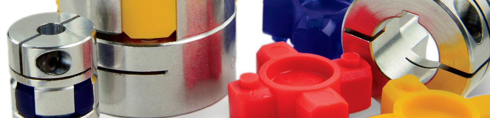
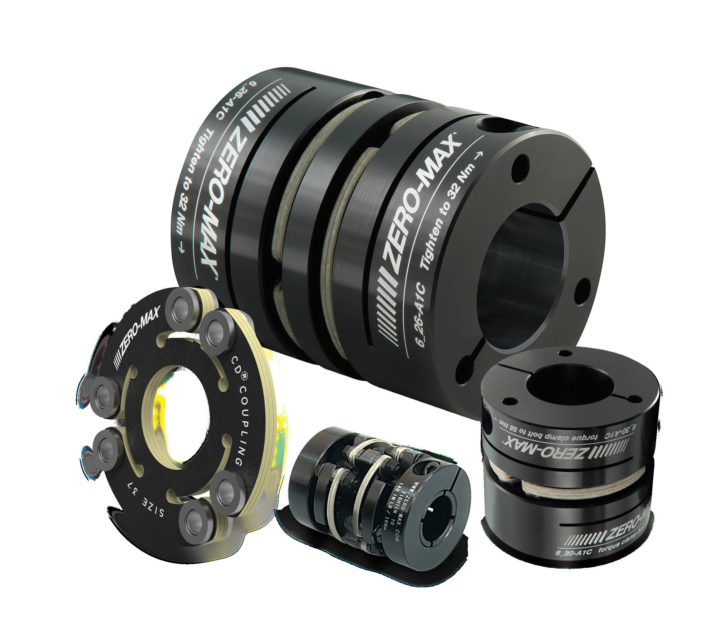
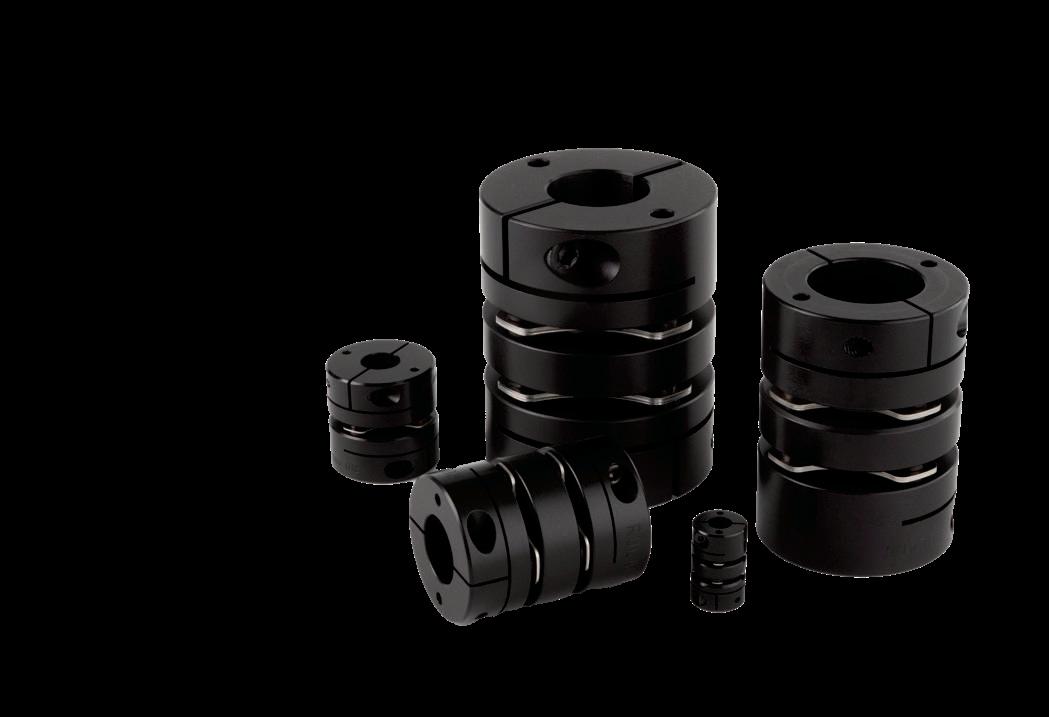
LARGE BORE DISC COUPLINGS
• Bore sizes up to 1-3/4” and 45mm
• Torque up to 1150 in-lbs (130 Nm)
• Reduced vibration due to a balanced design
• Double disc for increased misalignment
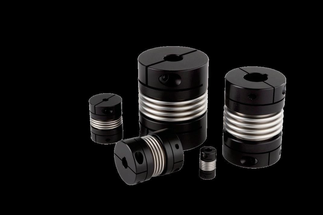
LARGE BORE BELLOWS COUPLINGS
• Bore sizes up to 1-3/4” and 45mm
• Torque up to 1300 in-lbs (152 Nm)
• Reduced vibration due to a balanced design
• Highest torsional stiffness
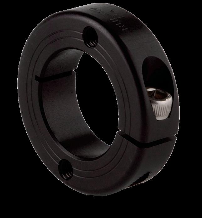
SHAFT COLLARS WITH FACE HOLES
• Maximum mounting flexibility with drilled holes
• Most secure mounting connection with thread- ed holes
• Bore sizes from 3/8”-2” and 10-50mm
• Carefully made by Ruland in aluminum, steel, and stainless steel
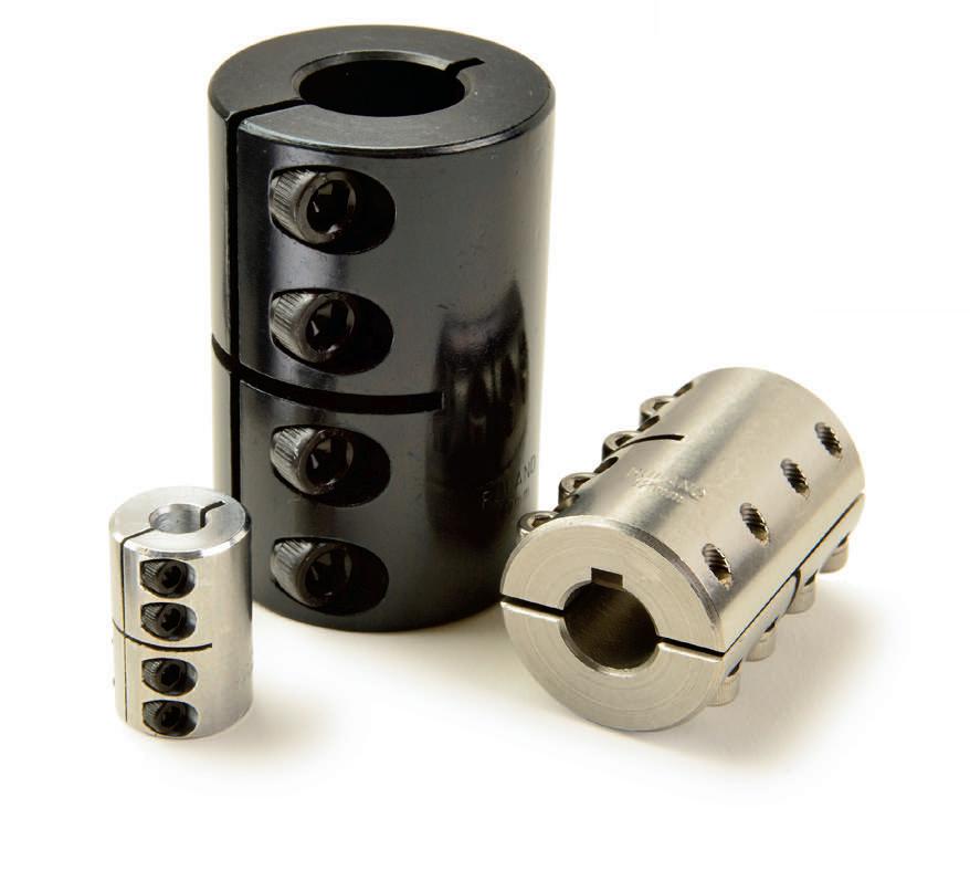
INCH-METRIC RIGID COUPLINGS
• Widest selection of standard inch-tometric bores with or without keyways
• Supplied with proprietary Nypatch® anti-vibration hardware
• One-piece style for easy installation
• Two-piece style with a balanced design
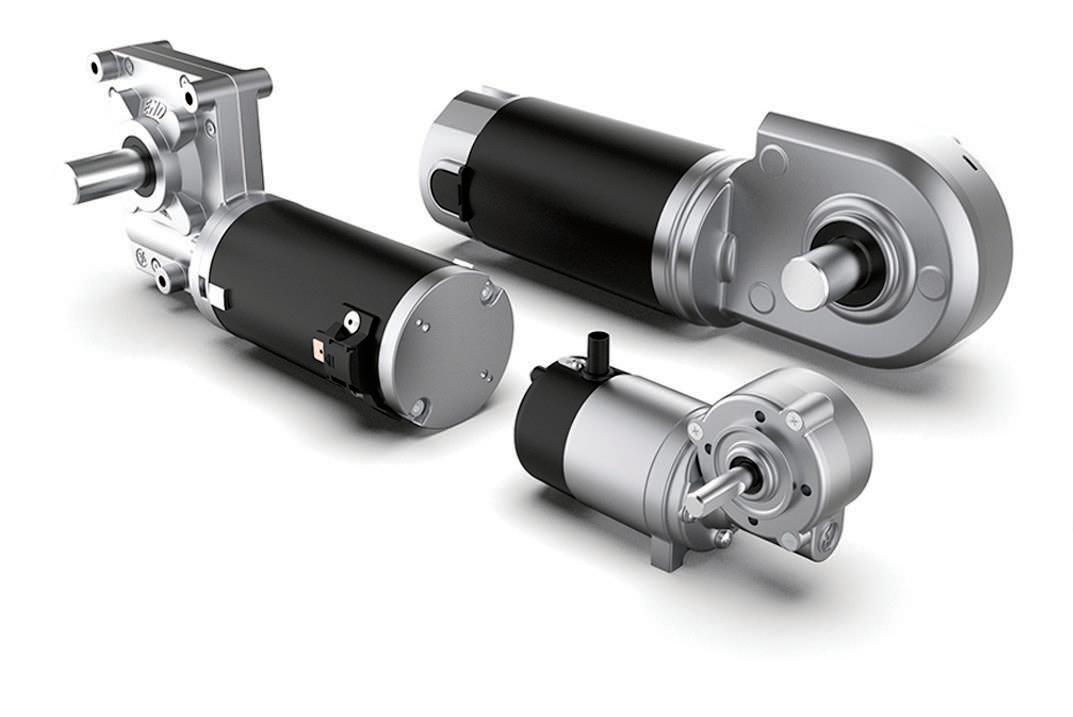
GEAR AND MOTOR CHOICES FOR LINEAR ACTUATORS
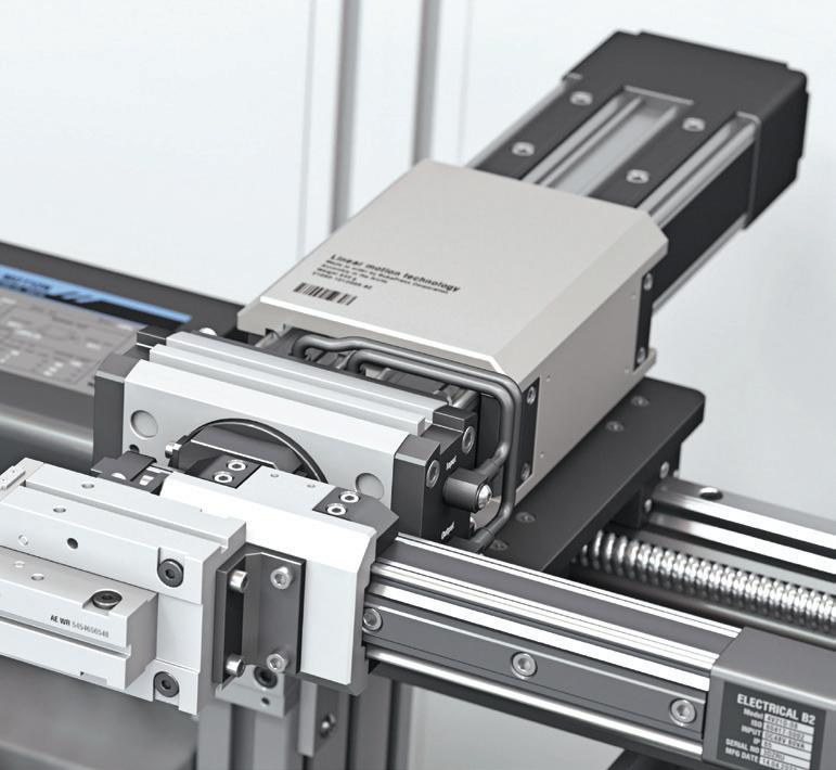
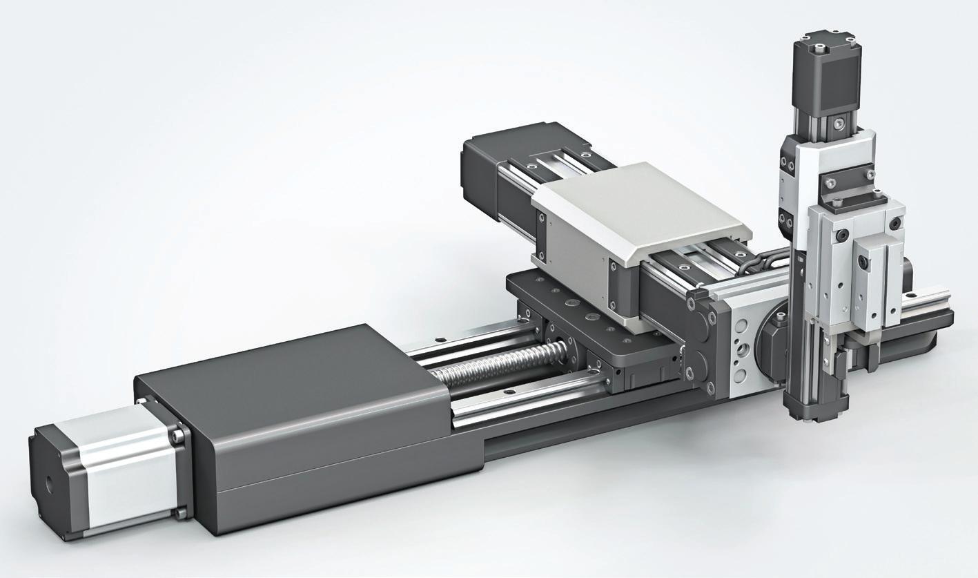
Linear actuators with belt drives, ballscrews, or leadscrews for their rotaryto-linear mechanical transmission most commonly pair with servomotors, stepper motors, or brushless motors. Belt-driven actuators frequently employ servomotors with planetary gearboxes for speed and precision. In contrast, ballscrew and leadscrew actuators often integrate servo or stepper motors that are coupled directly or via gear reducers to the linear mechanical drive.
No matter permutation, motors and their gearing connect to linear actuators via couplings such as zero-backlash bellows or elastomeric jaw couplings. Then the motor frame or gearbox housing mounts to the actuator body via machined aluminum or steel brackets. These are either standardized National Electrical Manufacturers Association (NEMA) mounts, metric flange mounts, or custom adapters to align the motor output shaft, coupling, and actuator input. Bracket flanges, pilot bores, tapped bolt patterns, or slotted bases enable fine-tuned alignment.
Gearboxes and motors may be separately specified for customization, but over the last two decades it’s become increasingly common for design engineers to specify motor-gearbox
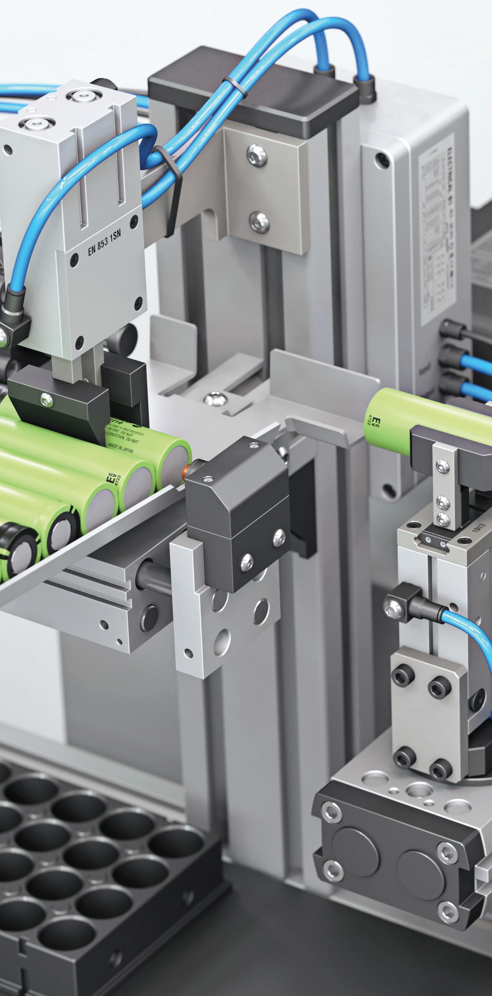
Image: Adobe Stock
12-V LINEAR ACTUATOR
MOTION-CONTROL
GEAR-BASED
MOTOR SCREW
CLUTCH
12-V linear actuator is a term common in industry referring to a self-contained unit containing a motor that runs off 12-V input and other motion components to deliver linear output.
assemblies pre-integrated by the supplier for easy installation with minimal misalignment or backlash. Pre-integrated units also optimize performance by reducing actuator tolerance stack-up and boosting actuator-assembly stiffness.
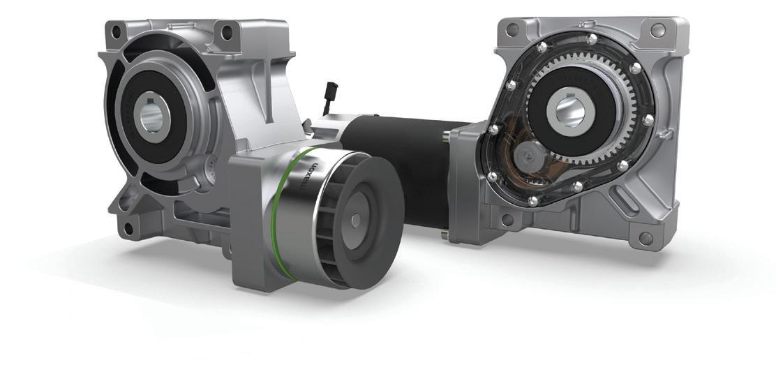
For speed reduction and to suit application requirements, linear actuators employ planetary, spur, worm, and bevel gearing (as well as right-angle variations). For example, spur gearing offers simplicity and compactness with moderate torque and speed reduction for mid-range precision applications. Spiral and hypoid bevel gearing offers compact right-angle transitions and high torque density for space-constrained designs or linear actuators to mount on and operate vertical axes.
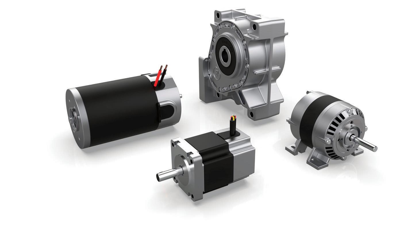
Most precision linear actuators with critical accuracy and repeatability requirements use ac motors (including servomotors) to get dynamic performance, torque density, and position control via closed-loop feedback and integration with a motion controller. However, another third or so of industrial linear actuators use dc motor variants such as brushless or stepper motors. Small linear actuators (especially those with leadscrews) employ
brushed dc motors as well, though not usually for precision automation. Rather, these actuators often work in consumer products, powered elements in automotive interiors, and medical equipment.
MOUNT GEOMETRY FOR LINEAR ACTUATORS
Most NEMA and metric motor mounts attach to the actuator drive end. Variations that accept right-angle or bevel gear drives feature side mounts; these can reduce actuator-assembly length in spaceconstrained machinery.
Mount brackets are made of machined aluminum or steel. Typical geometries include a square or circular flange with a center pilot bore (a precisely machined circular boss) and mounting holes in a standard array; four-bolt arrangements are common for averagesized motors. Mounting holes can be slightly elongated to facilitate slight adjustments.
The most common NEMA mount sizes are those for NEMA 17, 23, 34, and 42 motors. The numbers indicate the approximate dimensions of the motor faceplate. For example, a NEMA-23
motor has a 2.3 x 2.3-in. mount flange, and a NEMA-34 has a 3.4 x 3.4-in. flange. Even the bolt-circle diameters and tapped-hole patterns are standardized to allow interchangeability across motor brands and models.
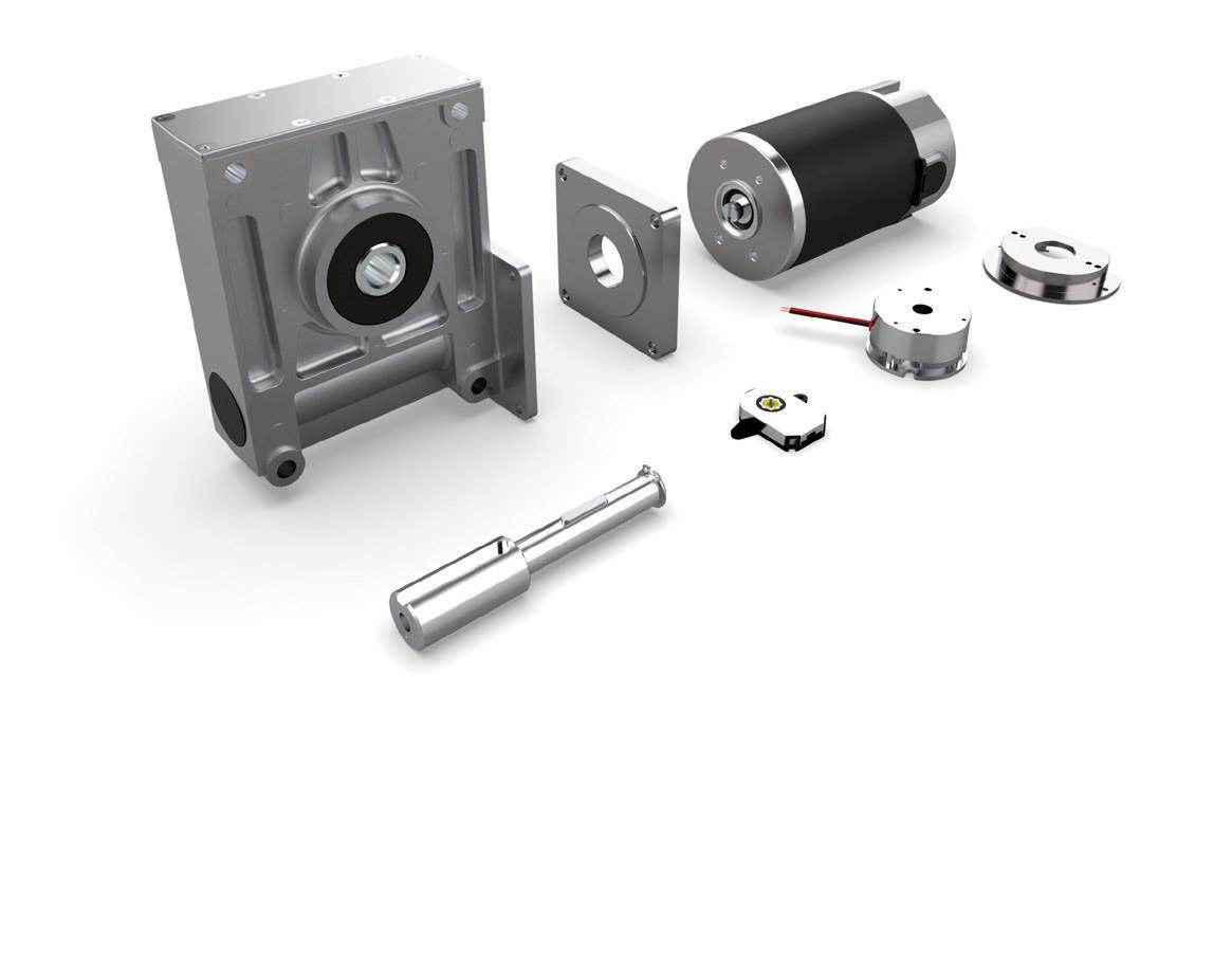
Metric motor mounts follow International Electrotechnical Commission (IEC) standards or manufacturer-specific metric dimensions defined by flange diameter — 60 mm, 80 mm, 90 mm, or 115 mm, for example. The circular flange has a center pilot bore encircled by symmetrically spaced bolt holes or slots. Common sizes are IEC56, IEC71, IEC80, IEC90; again, these names denote specific flange diameters and boltcircle patterns.
THE SPECIAL CASE OF 12-VOLT LINEAR ACTUATORS
Linear actuators are typically characterized by their drive mechanism — belt drive, ball or leadscrew drive, pneumatic drive, and so forth. But it’s not unusual for rod-style electric actuators to be classified by the input voltage — commonly 12 or 24 volts — of their integrated motors. These actuators provide thrust force, much such as a pneumatic or hydraulic cylinder. In fact, rod style electric actuators are widely used to replace pneumatic or hydraulic cylinders, due to their simplicity and the potential cost savings that can be realized by switching from fluid power to electrically driven motion.
As the name implies, a 12-volt linear actuator includes a 12-volt dc motor integrated into or tightly coupled with the actuator body. 12-volt actuators are driven almost exclusively by one of two mechanisms — a ballscrew or a leadscrew. Most designs incorporate gearing or use a gear motor to optimize the thrust and speed characteristics of the actuator. The most basic design includes a limit switch at each end of the stroke, meaning that the actuator fully extends and retracts, with no intermediate positioning. However, most manufacturers offer programmable limit switches as an option, for intermediate positioning capabilities.
Because these electric rod-style actuators are often used to replace hydraulic or pneumatic cylinders, some
of their basic design features follow the precedents set by the other technologies. Mounting is a good example. A 12-volt
linear actuator is typically mounted in the same manner as a pneumatic or hydraulic cylinder, with most having both clevis and trunnion mounting options. In some 12-volt linear actuator product lines, you’ll find body sizes and mounting options that meet ISO, NFPA, and other standards, which makes the conversion from a pneumatic or hydraulic actuator to an electrical actuator much simpler in existing applications.
Performance and selection: One of the most crucial differences between rod style and slider type actuators is that rod style actuators provide only thrust force. Their primary use is for pushing or pulling a load, via a tube or rod that extends and retracts from the actuator. While a plain bushing guides the rod, there are no linear guides to support and carry the load. In most applications, support and
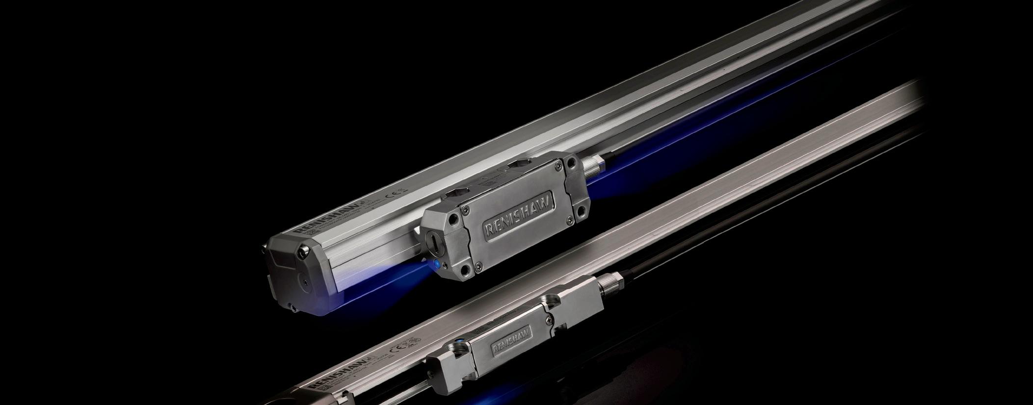


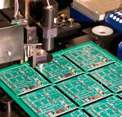
Image: Adobe Stock
Our Certifications
ISO 9001 + AS9100
ITAR Compliant-DDTC Registered
DFARS Compliant
RoHS & R.E.A.C.H. Compliant
NIST SP 800-171 Compliant
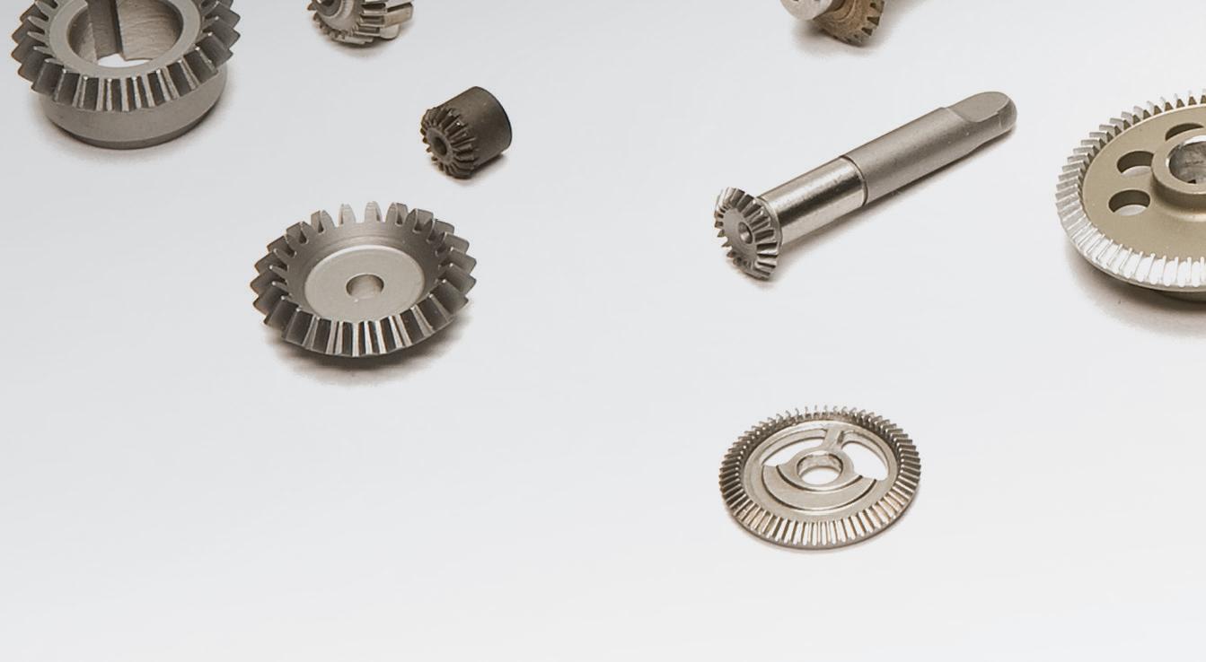
Precision Gears and Superior Mechanical Components

Turning Ideas into Reality since 1950
Engineering development, design, and manufacturing expertise combined with mechanical and electromechanical component options.
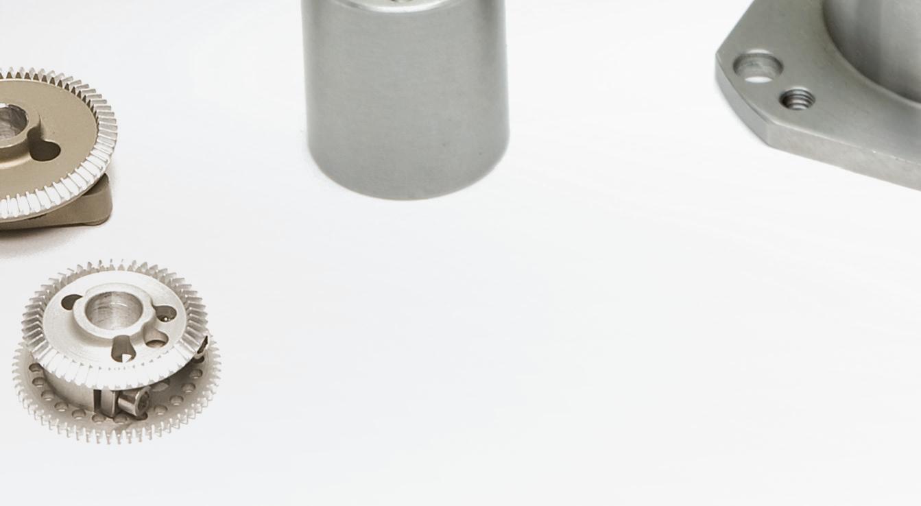
Streamline Your Supply Chain
We deliver parts and subassemblies complete, eliminating your need for additional sourcing, time, and cost.
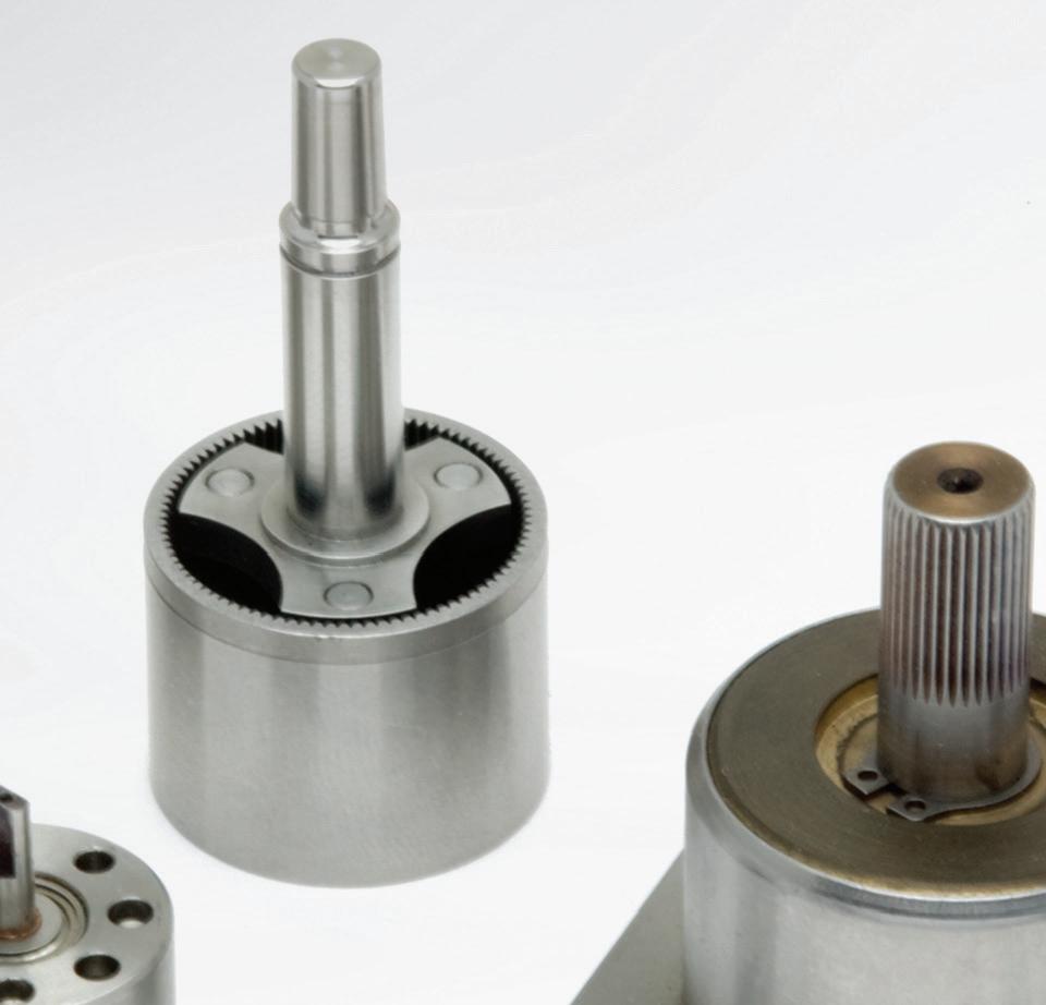
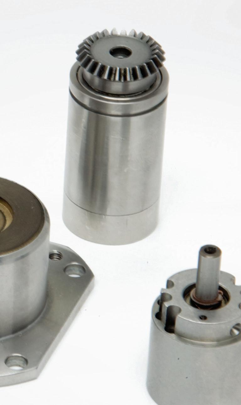
Customized Solutions
Custom Gears & Mechanical Components
Custom Gearheads & Gearboxes
Complex Gear Assemblies
Mechanical Assembly Electromechanical Assembly


guiding for the load is provided by tracks or rails independent of the actuator. This operating principle explains why these actuators have several different monikers, including electric cylinders, thrust type actuators, and rod style actuators.
Sizing and selection of a 12-volt linear actuator is fairly straightforward, because the motor is preselected and integrated into the actuator. The first parameter to be considered is typically thrust, as it will often dictate the overall body size of the actuator. Next is stroke length, since a small actuator may meet the thrust requirements, but may not be able to achieve the necessary stroke length.
Like slider type linear actuators, rod-style actuators driven by a ballscrew or leadscrew can back drive. When the application requires vertical operation, remember to check that the vertical load doesn’t exceed the back driving torque of the screw.
With an initial actuator selection based on thrust force and stroke, the
1/3

speed and duty cycle requirements can then be checked. The allowable force and speed combinations are typically provided by the manufacturer, in the form of a performance curve or chart. Once it’s confirmed that all other parameters are within the actuator’s capabilities, it’s important to check the needed duty cycle, or on time — because motor heating can be a limiting factor for the actuator’s performance.
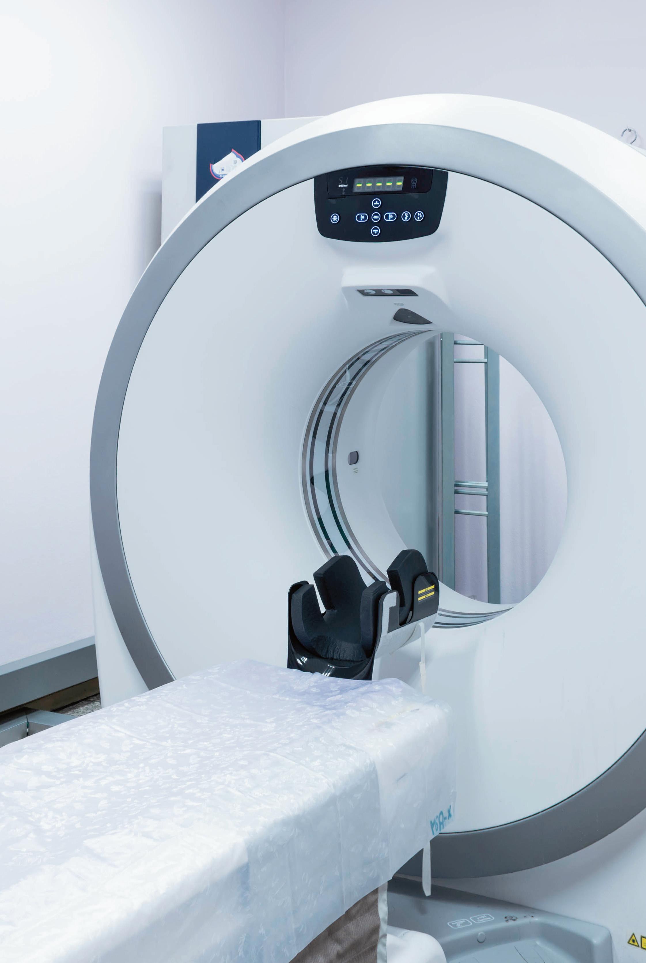
Suitable applications: Virtually any time a load must be pushed or pulled, without being guided or carried, a rod style actuator is a good choice. This includes opening and closing sliding doors in applications such as rail cars and machining centers. In the medical industry, 12-volt actuators are often used for ergonomic positioning of worktables or patient beds.
In conveying operations, these actuators are commonly used to stop or divert product along the conveyor, depending on the process requirements. Plus because they’re fully enclosed and available in IP-rated or hygienic designs, rod-style actuators are suited for the pharmaceutical and food and beverage markets, where purely thrust operations (such as inserting, labeling, or stamping) are typical.
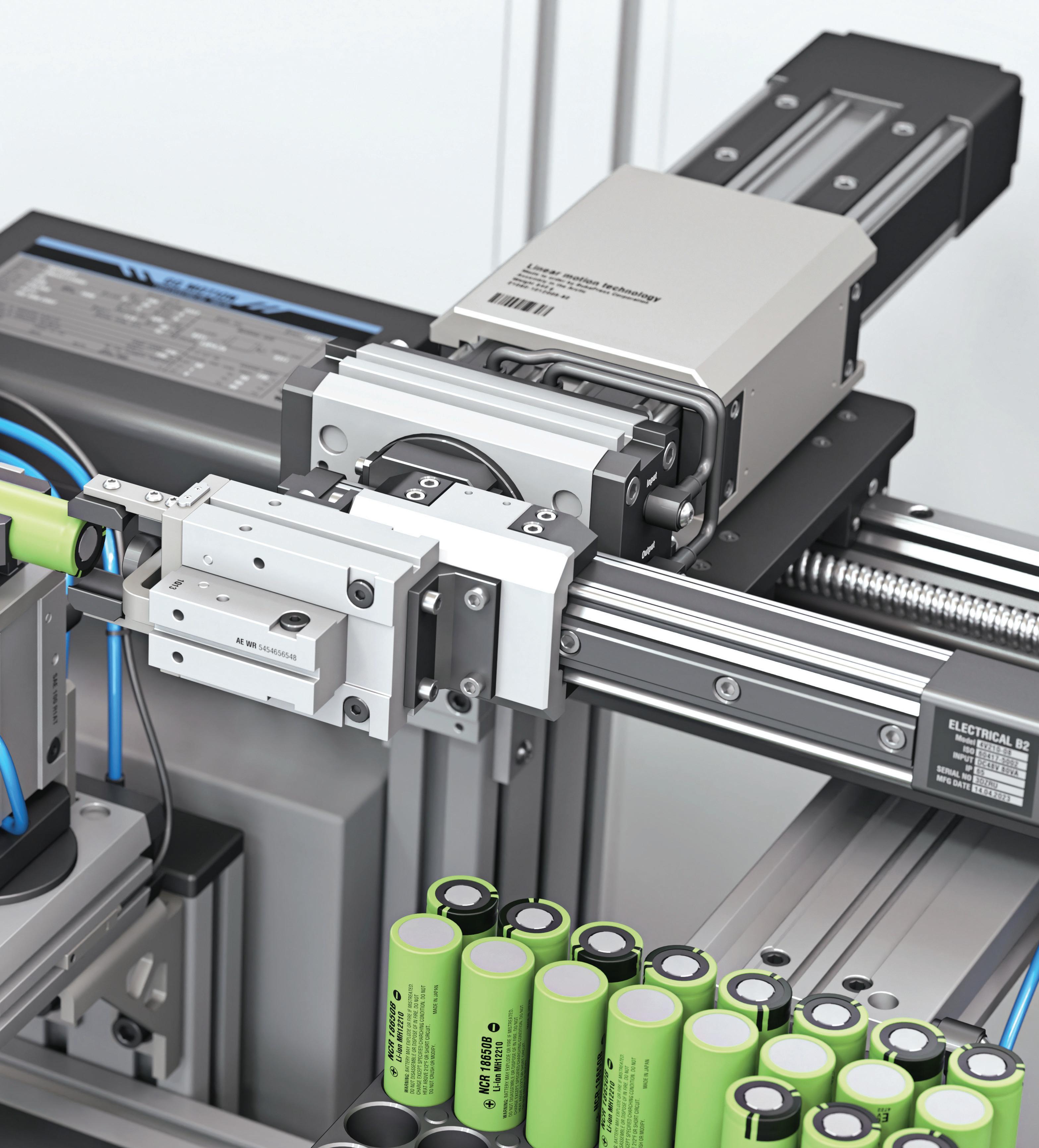
In multi-axis linear-actuator systems based on motors with NEMA-standard features (for example, in NEMA 17, 23, 34 sizes) NEMA mounts simplify assembly.
Image: Dreamstime


WHAT’S REALLY THE DIFFERENCE BETWEEN A DC SERVO AND AN AC SERVO SYSTEM?
If a draw operation needs dynamic smoothing of inconsistent material, sometimes the leading solution is one with low motor-rotor inertia and high feedback resolution.
This article provides a history and general guidance on the capabilities of ac and dc servo technologies.
BY HURLEY GILL
SENIOR APPLICATIONS AND SYSTEMS ENGINEER KOLLMORGEN
Many of today’s industrial and commercial applications — whether controlling a specific operation or just some specific motion — require electric motors. These electromechanical solutions typically set the performance limits and capabilities of machine axes and thus the operations being performed. That’s true in manufacturing applications and elsewhere.
Performance limits and capabilities affecting a given operation can be enhanced to boost product quality, throughput, and more with the addition of automated closed-loop control.
Designs with such closed-loop control function as servomechanisms typically associated with the word servo — often commanding the specific axis’ force or torque, velocity, and position. A closed-loop system is most simply defined as a driven mechanism dependent upon instantaneous feedback data from the continuous monitoring of a given operation or process resulting in systematic adjustments of that same primary operation for the accomplishment of a desired outcome.
Image: Adobe Stock
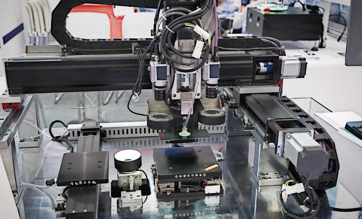
Pick-and-place

Today, a closed-loop system is generally identified as a servo system. For controlled mechanical motion, this is generally accomplished by the usage of an ac or dc servomotor. A servomotor (whether considered ac or dc) is basically a bidirectional servo actuator under closedloop control that …
Uses data from instantaneous feedback monitoring of actual motion (as position, velocity, and torque or force) …
Against commands or setpoints to cause dynamic-corrective adjustments (± the difference between the two) of a given operation for a precise outcome.
Whether the servomechanism is designed using an ac or dc servomotor, each axis of motion is individually controlled by converted electrical signals based on programmed information. So, the servomotor’s response is continuously monitored for continuous calculations
against a desired command (setpoint) resulting in a continuous series of corrective adjustments.
In other words, regardless of the job to be performed by a machine or machine axis, the limiting condition is typically established by the available response times of the electromechanical components from which a given servomechanized machine is composed.
A servo (closed-loop) control system allows for the control and manipulation of an axis’ dynamic response relative to the machine operations’ load disturbances and so on. Performance is optimized through the use of a proportional, integral, and derivative (PID) servo controller algorithm. Further optimization of the electromechanical response is possible when the best available technology is selected for the application.
Servomotors have evolved over the years, and various technologies have become common in precision motion control. Initially, these systems
were mostly industrial dc motors, driven by an ac motor-to-dc-generator set, with tachometer feedback for continuous velocity monitoring — and when applicable, there was continuous monitoring of axis position by a separate feedback sensor (such as an encoder or resolver).
Later these industrial dc systems were replaced with permanent-magnet (PM) dc brush servomotors driven by:
• Linear drive technologies, then
• Chopper (silicon-controlled rectifier or SCR) drive technologies, then
• Pulse width modulation (PWM) bipolar junction transistor or BJT drive technologies.
Rather quickly, most of these dc brush servomotors were replaced with electrically commutated permanentmagnet motors — including brushless dc (BLDC), ac (PM AC), and even some ac induction (asynchronous) servomotors. The terms brushless dc servo and ac permanent-magnet (PM) servo were first established to promote the adoption of these motors and to promote the idea that ac permanent-magnet motors with electronic commutation could effectively replace permanent magnet dc brush servomotors. Additionally, because of different electronic commutation technologies, the industry developed naming conventions related to counter or back electromotive force (Bemf) characteristics. Today, these widely used names are trapezoidal for sixstep commutation (and vice-versa) and sinewave for sinusoidal commutation (and vice-versa).
To be clear, originally the distinctions between BLDC, ac PM servo, and ac servo arose not solely from technological differences. These names were also part of marketing efforts to dispel misconceptions about the capabilities of electronic commutation in comparison to mechanical commutation of dc servomotors.
For this discussion, we assume servo designs and servo systems refer to complete solutions that include a servomotor, servo drive, and monitoring
applications make copious use of servomotors.
Image: Adobe Stock
feedback sensor(s).
In fact, BLDC and ac PM servomotors basically feature the same type of permanent-magnet motor construction. In some cases, they’re just styled with slightly different magnetic designs to further reduce core losses. So actually, the two terms BLDC and ac PM servo describe the commutation method used to control power to the permanent-magnet motor. Standard motors of both designs are three-phase PM — ac synchronous — servomotor designs.
Hence it’s the specified drive’s commutation type that influences which motor construction is most suitable — in other words, for best performance the servomotor is specifically designed for a designated commutation technology. Otherwise, either style servomotor may be driven by either commutation type notwithstanding feedback-sensor
differences or servo drive requirements. However, one can expect slightly less energy losses (generally negligible) when the motor’s Bemf design style matches the drive’s commutation topology.
There are two basic types of commutation technologies — six-step (or trapezoidal) commutation and sinewave (or sinusoidal) commutation. The electrical cycle of the former commutation method is effectively defined into six distinct dc-style steps. The latter is defined by its comparatively smooth and continuous ac-style waveforms.
The electronic commutation of a servo drive with six-step (trapezoidal) commutation topology limits the motor’s applied voltage to only two of the three motor phases at any given time. That’s because one of the three phases is always off even though the dc-stepped waveform
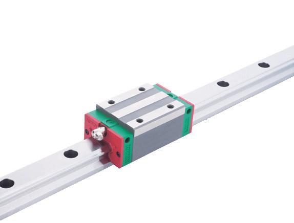
SMOOTH OPERATORS ROTARY MOTION COMPONENTS
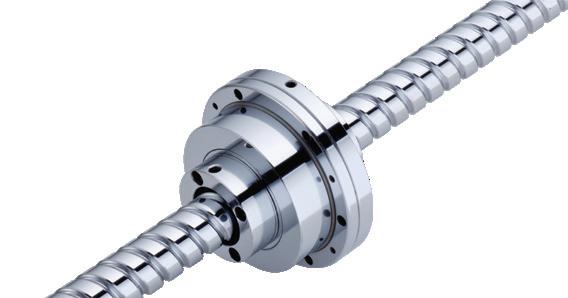
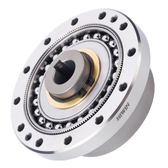
DATORKER® STRAIN WAVE GEARS
Available in Standard, Heavy Load, and Lightweight Configurations. Offering High Precision, Efficiency, Torsional Rigidity, and Low Starting Torque.
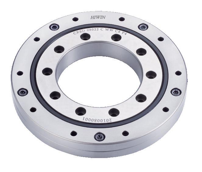
CROSSED ROLLER BEARINGS
Lightweight And Compact Design. Easy to Install and Maintenance. Varieties of Bearing Types and Sizes for Solution.
is basically trying to emulate a sinewave.
In contrast, with sinewave commutation topology, the supply voltage is applied to all three motor phases at the same time (as with any typical 3 φ motor). That’s true whether the drive is controlling an ac PM (synchronous) servomotor or an ac induction (asynchronous) servomotor.
Compared here in broad terms (and with no consideration as to availability) are key differences between dc servo and ac servo technologies. Listed capabilities are typical standard values without excessive expenditures.
These different commutation methodologies lead to the use of different parameter units for the identification of motor and drive characteristics. These parameter units can be differentiated from each other and converted to and from one another by referencing the commutation type to be employed. Discrepancies and misunderstandings about this data and listed units on motor datasheets

Our engineers are available to assist in finding the ideal solution to your application. Contact us for details.
WHERE DIFFERENT SERVO SYSTEMS EXCEL
Motor type (typical identification)
Drive amplifier type (technology method delivering power)
Commutation type Mechanical
Commutation (typical identification) Commutator
Commutation control or electrical sensing type Rotating switch Hall
Control type availability Torque control (typical) current-loop feedback • external or via power module (typical)
Velocity control velocity -loop feedback • digital feedback • displacement per sample-of-time typically replacing analog tachometer***
Position control position -loop feedback (typical) Digital resolution counts per displacement
Feedback possibilities (typical)
Capabilities
Resolver • analog converted to digital
Sine encoder • analog/digital optical
Sine encoder • analog/digital inductive
Sine encoder • analog/digital capacitive
Encoder (TTL)
Highest torque density
Largest torque and speed range
Highest velocity (potential)
Highest bandwidth response times
Highest acceleration/deceleration
Maintenance (lowest expected)
Hold position (steadiest)
Position precision capability (likely highest)
Precise control of velocity (smooth speed operation)
Precise control of torque (tension etc.)
Rotor inertia (minimal for a given torque capability)
Rotor inertia maximum for a given torque capability
Fastest corrections against disturbances and new commands
Peak torques available (highest) as for continuous capacity
Highest resolution (typical) sine encoder and could be used with any
Harshest environments resolver feedback and could be used with any
Low input voltage down to ~16 Vac or ~ 24 Vdc-bus
High -input voltage to 480 Vac
Highest efficiency
Highest product throughput
Highest precision (with high -resolution feedback )
Highest availability of mechanical options ( as for mounting)
Lowest cost (potential present day)
Easiest to customize (windings)
Bidirectional capability
* Encoder with emulated Hall signals.
** Halls or emulated Hall signals may be used to set initial commutation angle on startup.
*** Today, high resolution position sensors offer resolutions high enough to eliminate most needs for tachometers.
**** Application dependent at more than 200 rpm; best at high rpm (as on a spindle).
***** Application (inertia) dependent.
****** With an analog tachometer.
can lead to flawed interpretations and suboptimal operation. Understanding servomotor-parameter nuances and their proper application is essential for optimal performance, reliability, and diagnosis of mechanism-operation issues. For more information, read the white paper, Servomotor parameters and their proper conversions online.
Choosing the servo technology, control method, servomotor, and feedback to use for a specific electromechanical design can be daunting for the beginner engineer. However, the best selection for a given application becomes clearer once the advantages and disadvantages of different servo technologies are understood. That’s especially true when a given servo technology will definitely best satisfy an application’s core function and specifications. Here, the servomotor must first satisfy repeatability, accuracy, and flexibility requirements for present and future needs. Then remaining considerations typically relate to component availability, machine life expectancy, operating environment, allowable noise, and target efficiency.
On the other hand, when either servo technology might satisfy a given application’s requirements, one should use discernment and foresight and carefully catalog everything known about the application, possible future needs, and the designer’s experience.
To illustrate, following are three application examples and their basic requirements.
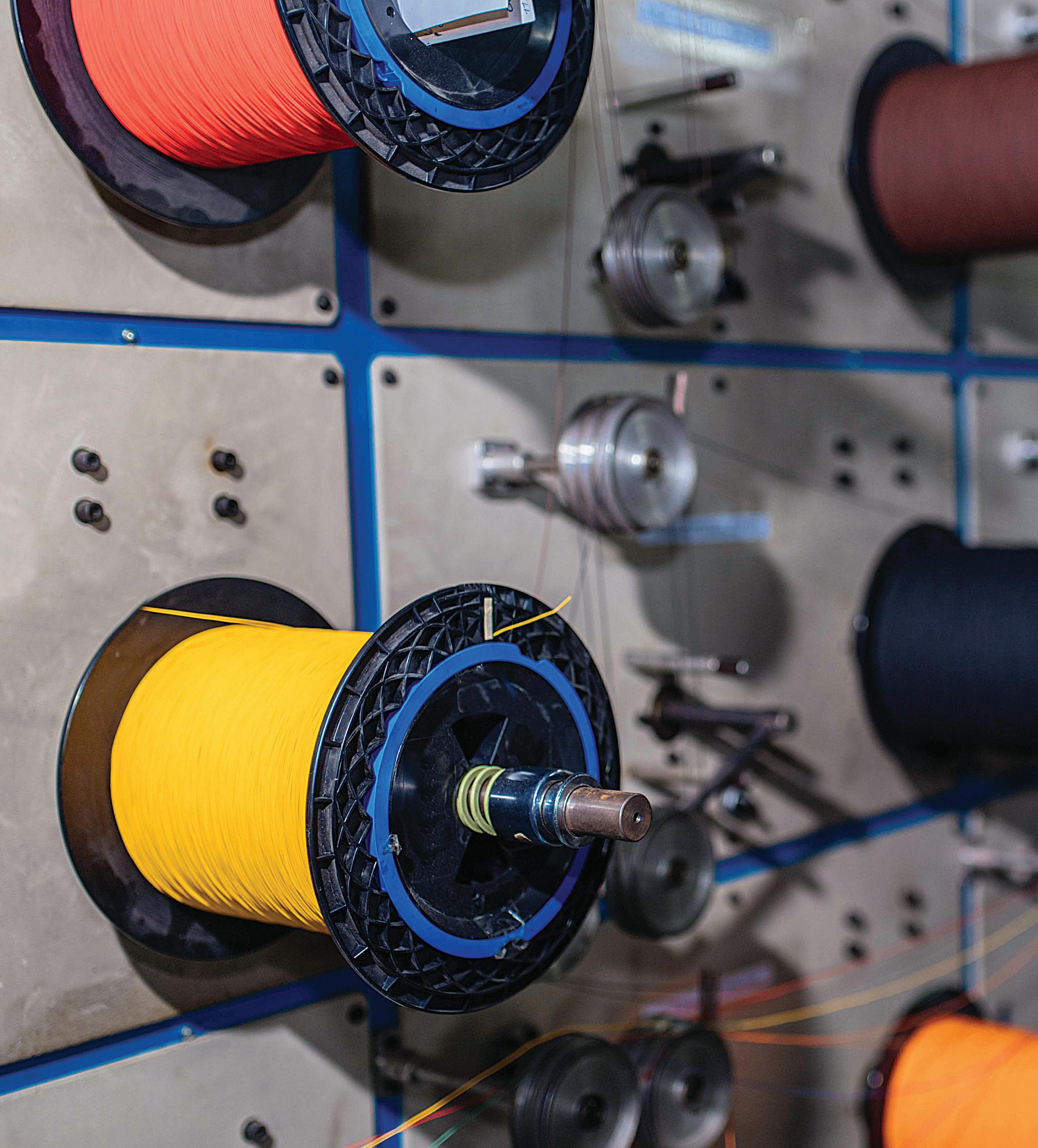
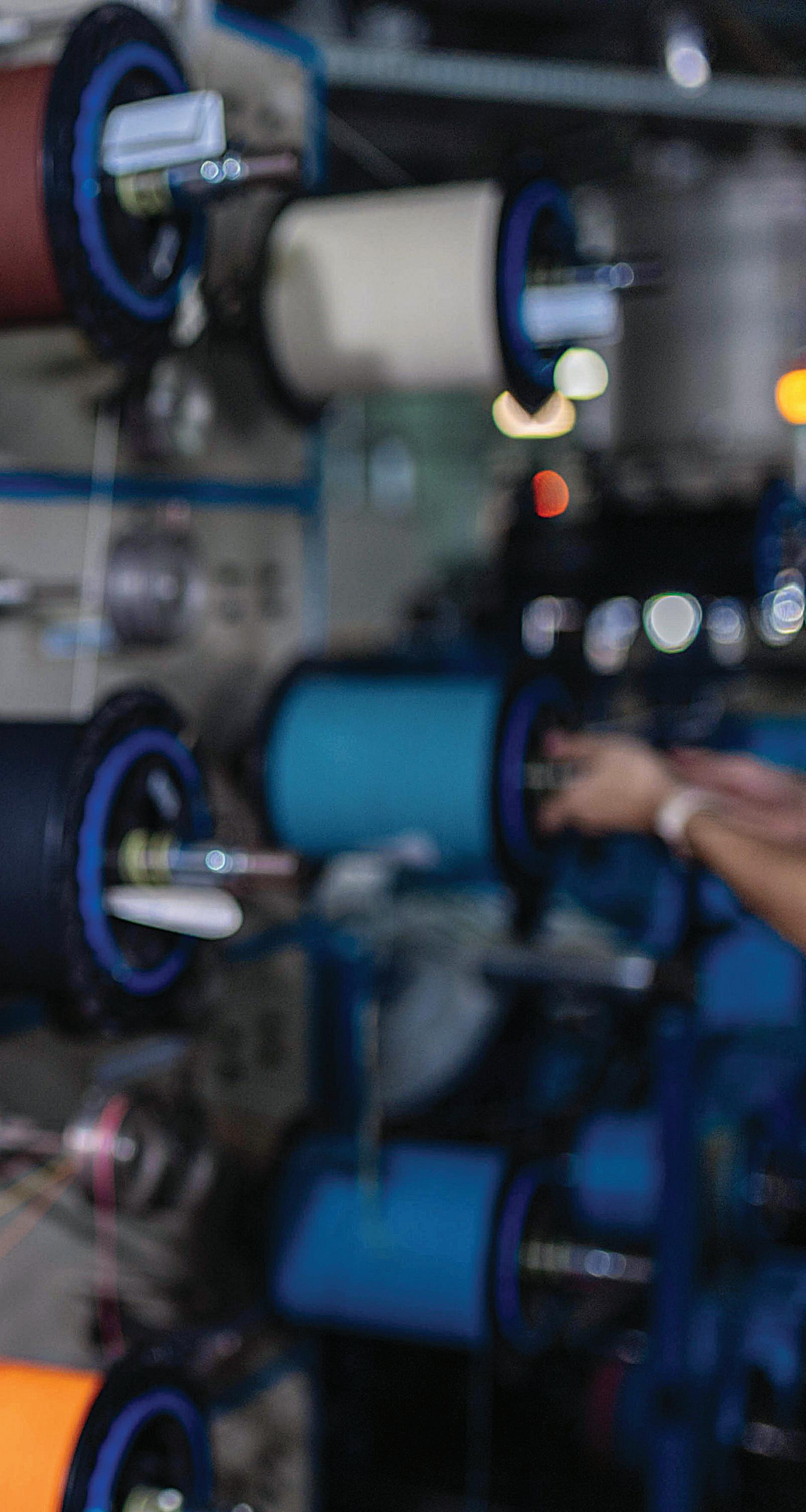
Example application one: A filament or fiber-drawing application often requires a tight short-term and a more open long-term, velocity tolerance. This tight velocity requirement may be best solved with an electromechanical servo system featuring:
• Relatively large rotor inertia to help dampen instantaneous disturbances.
• Relatively high feedback resolution to help maintain the long-term velocity specification — perhaps even to the point controlling velocity within an effectively infinite position loop (i.e. to the limit of the drive’s capability).

However, if the draw operation requires dynamic smoothing of inconsistent material over short distances, relatively low rotor inertia and high feedback resolution will be a better solution. That’s because needed bandwidth response times can be met at the target production velocity rate.
Example application two: For typical pick-and-place or point-to-point positioning applications, the specific operation dictates the acceptable range of position. So, the dominant attribute is repeating accelerations and decelerations (whether or not there are any constant-velocity traversals during a move). On vertical axes, the motor must also be capable of holding the load against gravity.
For such repeated accelerations and decelerations, mechanism solutions with lower mass or inertia are best — even if the application doesn’t need highly repeatable or accurate final positioning with or without tight settling times.
At this point, the primary design objectives are control stability, operating environment, initial cost, and energy operating expenditures. Industrial or commercialized robot requirements present the ultimate challenge for a multiaxis design often requiring increased axis repeatability or accuracy during positioning, acceleration, deceleration,
traverse displacements (and even while holding loads) for the fulfillment of some specification for multi-axis coordination.
Demanding requirements often indicate the use of highly repeatable and accurate feedback devices (which in turn must be suitable for the operating environment).
Example application three: For autonomous mobile and cobot applications, priority requirements are likely safety and energy expenditure. That’s because these designs can potentially share space and have direct interactions with human personnel during normal operation. Plus, these applications — in addition to the common criteria of environmental suitability and ability to carry or hold a load — often have exacting stop-function requirements. That’s because cobots and mobile designs must be able to quickly respond to unexpected events. Such designs (especially if battery powered) must be energy efficient.
These safety and energy requirements indicate solutions with the lowest possible mass or inertia — even when the application doesn’t necessarily need highly repeatable or accurate positioning from the servo-controlled axes. •
KOLLMORGEN | KOLLMORGEN.COM
Autonomous-vehicle applications have their own unique servomotor requirements.
Image: Adobe Stock
AD INDEX
EDITORIAL
VP, Editorial Director Paul J. Heney pheney@wtwhmedia.com
Chief Editor Rachael Pasini rpasini@wtwhmedia.com
Executive Editor Lisa Eitel leitel@wtwhmedia.com
Managing Editor Mike Santora msantora@wtwhmedia.com
Senior Editor Miles Budimir mbudimir@wtwhmedia.com
SALES
Ryan Ashdown rashdown@wtwhmedia.com 216.316.6691
Jami Brownlee jbrownlee@wtwhmedia.com 224.760.1055
Mary Ann Cooke mcooke@wtwhmedia.com 781.710.4659
Jim Dempsey jdempsey@wtwhmedia.com 216.387.1916
Mike Francesconi mfrancesconi@wtwhmedia.com 630.488.9029
Jim Powers jpowers@wtwhmedia.com 312.925.7793
CREATIVE SERVICES & PRINT PRODUCTION
VP, Creative Director Matthew Claney mclaney@wtwhmedia.com
Senior Art Director Tory Bartelt tbartelt@wtwhmedia.com
Director, Audience Growth Rick Ellis rellis@wtwhmedia.com
PRODUCTION SERVICES
Customer Service Manager
Stephanie Hulett shulett@wtwhmedia.com
Customer Service Representative Tracy Powers tpowers@wtwhmedia.com
Customer Service Representative JoAnn Martin jmartin@wtwhmedia.com
Customer Service Representative Renee Massey-Linston renee@wtwhmedia.com
Customer Service Representative Trinidy Longgood tlonggood@wtwhmedia.com
ONLINE DEVELOPMENT & PRODUCTION
Web Development Manager B. David Miyares dmiyares@wtwhmedia.com
Senior Digital Media Manager Patrick Curran pcurran@wtwhmedia.com
Digital Production Manager Reggie Hall rhall@wtwhmedia.com
LEADERSHIP TEAM
Senior VP, Engineering Courtney Nagle cnagle@wtwhmedia.com 440.523.1685
CEO Matt Logan mlogan@wtwhmedia.com
CFO Ken Gradman kgradman@wtwhmedia.com 773.680.5955
FINANCE
Controller Nirmit Shukla nshukla@wtwhmedia.com
Accounts Receivable Specialist Jamila Milton jmilton@wtwhmedia.com
MARKETING
VP, Operations Virginia Goulding vgoulding@wtwhmedia.com
Digital Marketing Manager Taylor Meade tmeade@wtwhmedia.com
Digital Design Manager Samantha Goodrich sgoodrich@wtwhmedia.com
Webinar Manager Matt Boblett mboblett@wtwhmedia.com
DESIGN
DESIGN


Subscriber
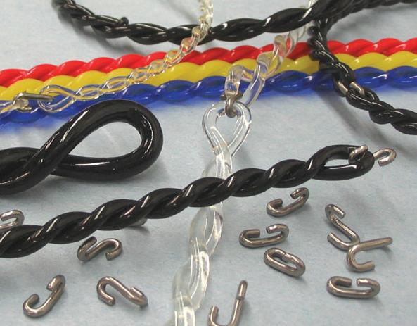
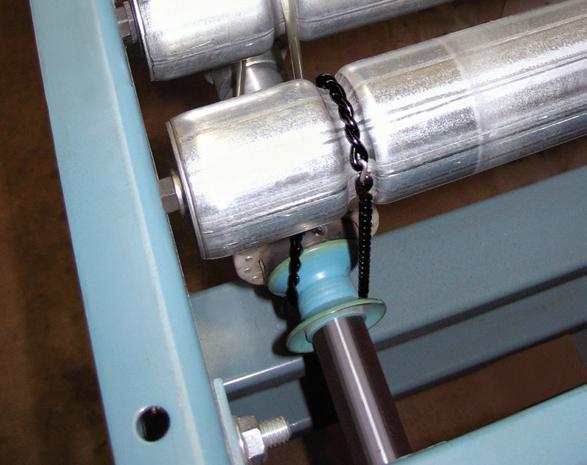
DRAW-WIRE SENSORS IN CONTEXT
The term linear-position sensor often indicates some device employing an analog or digital signalgenerating assembly based on electromechanical potentiometric, electrolytic, capacitive, inductive, or magnetic operation — with the latter including various magnetoresistive, Hall effect, and magnetostrictive permutations. Where the term linear position sensor is used without any other context, it usually implies a linear variable differential transformer (LVDT) — one particularly
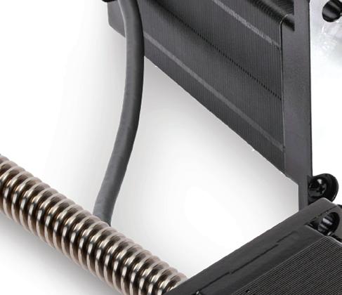
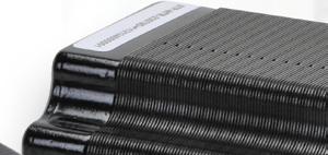
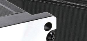
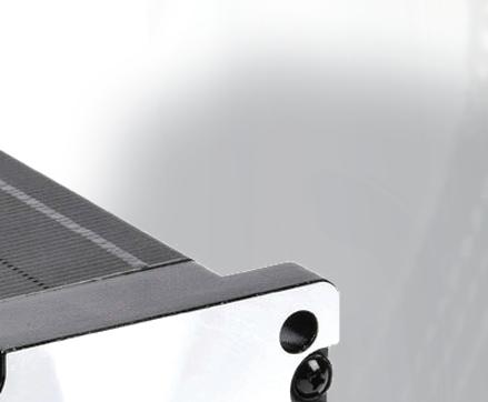
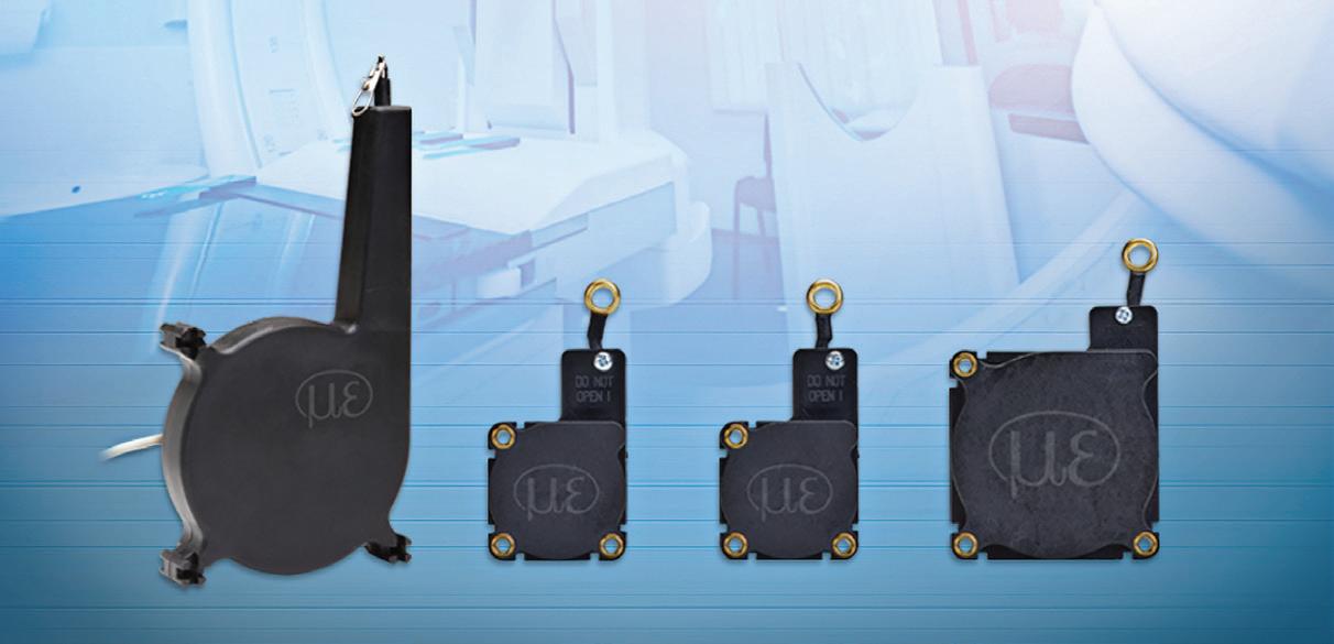
TOP:
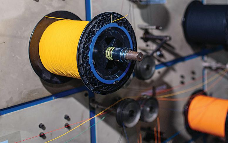
Micro-Epsilon K and MK draw-wire sensors are specially designed for series production and OEM applications. Depending on the model, they measure distances from 50 mm to 8 m and can be used at temperatures from -40 ° C to +85° C. The wireSENSOR WPS-K100 sensors are robust thanks to glass-fiber-reinforced plastic housings imparting protection to IP67 or IP69K. A separate drum and spring chamber protects the spring — even when put into outdoor applications. Signals are output via CANopen (digital) or via potentiometer, current, or voltage (analog).
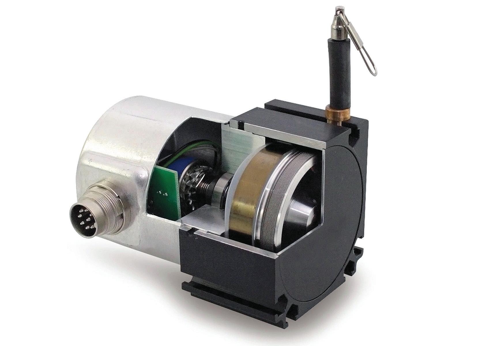
BOTTOM:
Draw-wire sensors track the mechanical retraction of flexible wire attached to an object on the free end via a sensor on a spool contained in a housing.
common and useful technology. Elsewhere, the term linear displacement transducer (abbreviated LDT) is used. This usually refers to magnetostrictive-based linear sensors that compete with potentiometric-based sensors in the machine tool, office automation, and paperprinting industries.
That said, some technical sources use LDT to also refer to linear potentiometers as well as draw-wire linear transducers containing rotary potentiometers.
Consider draw-wire sensors. Called string potentiometers, cable-extension transducers, or wire-actuated encoders, these track the mechanical retraction of flexible wire (often stainless) attached to a tracked object on the free end and wound around a spring-loaded spool on the other end. Depending on the technology, the spool can couple to a potentiometer, rotary encoder (optical or magnetic), or magnetic sensor. This internal sensing element in turn generates an analog voltage, current, or digital pulse output.
Draw-wire sensors are specified to satisfy stroke reach, resolution, repeatability, and ruggedness. Some are suitable for OEM and series applications — especially for their priceperformance ratio and robust construction — primarily in mobile machinery such as telescopic handlers or mobile cranes, medical equipment, and industrial applications.
Thanks to their compact dimensions, the sensors are also suitable for applications with limited installation space. Some can be customized for special OEM requirements not satisfied by standard models. Economical implementation is often possible even for low-volume applications. •
Image: Micro-Epsilon
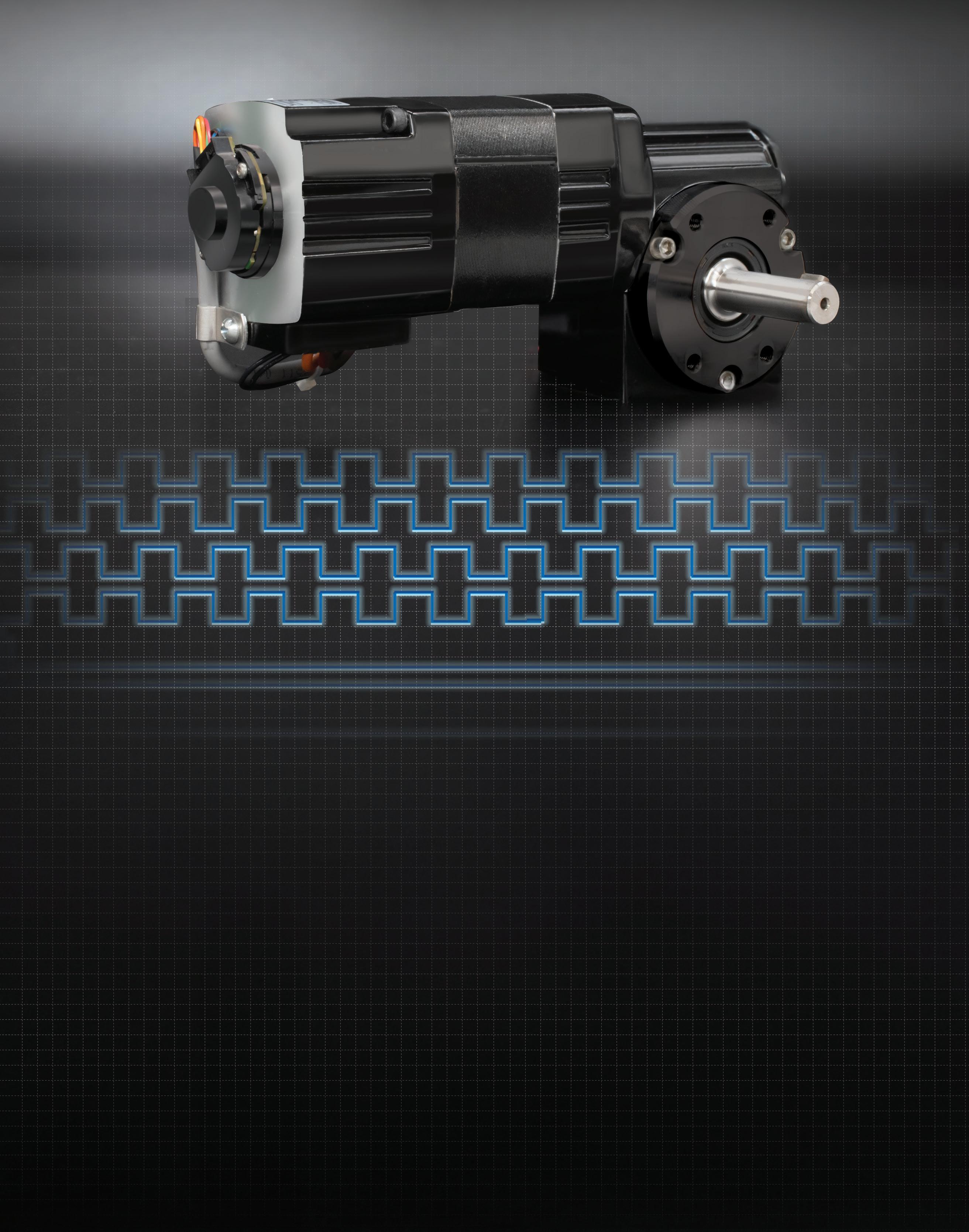
Put an encoder on it.
Combine an encoder with a Bodine gearmotor and instantly communicate the speed, direction and position data that today’s IIoT applications demand. Choose from an accessory-ready model, a stock encoder-gearmotor combo, or a custom gearmotor with the encoder of your choice already installed and tested. Any way you choose it, a Bodine gearmotor with an encoder will start – and stop – and start – and stop your servo application.
Check out our case study to see how Bodine design engineers helped develop a custom gearmotor for an automated guided vehicle.