

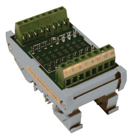
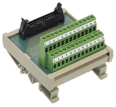
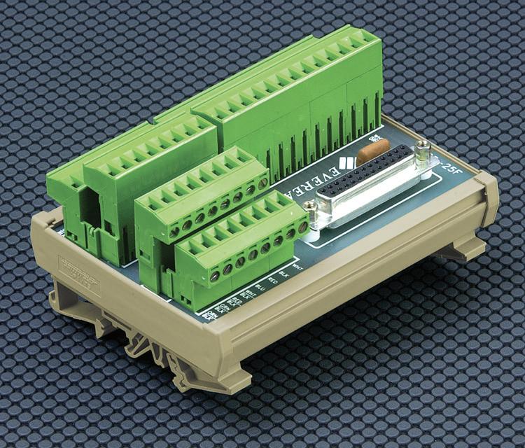
Compact and reliable transitionsbetween high density connectorsand high quality screw-cage clamp terminal blocks.
• FBK Ribbon Cable, up to 64 poles
• Subminiature - D, up to 50 poles

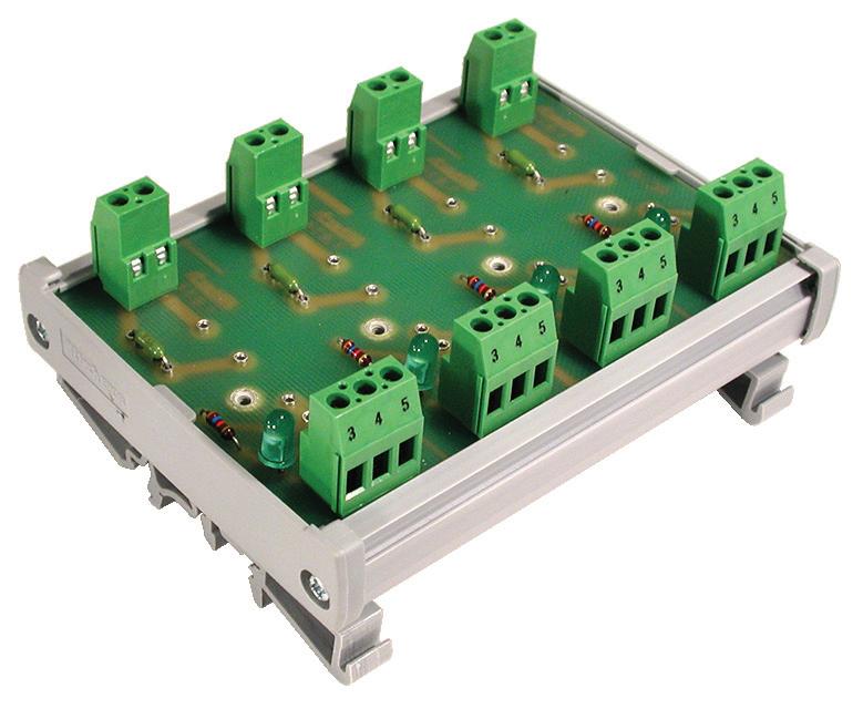


Use our Diode Modules to build lamptest circuits, decouple signals, etc. Mount your own components into our Component Carriers (supplied without electronic components). Or, tell us whatyou need and we’ll install it for you.

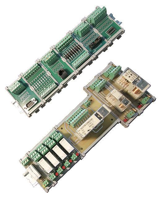
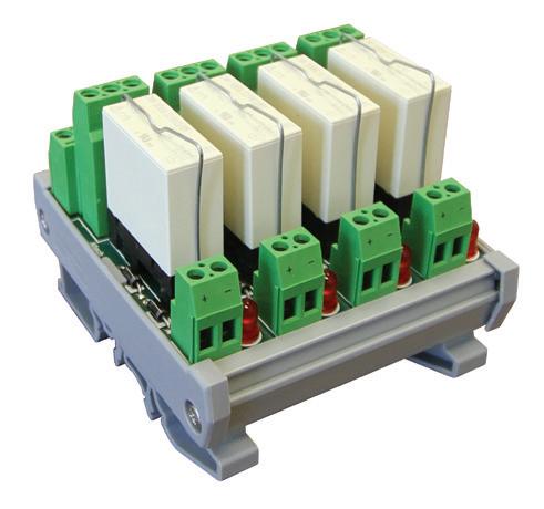
Traditional relay and safety relay modules in a high density package.
• Protect equipment
• Provide insulation
• Control motors, solenoid and valves
• Safety relays for emergency stop, safety gate and two-hand stop
• DM Diode Modules have series connection 1A or 3A diodes, and 1A diode gates with common cathodes or anodes, providing commonly used diodearrangements
BSM Component Carrier has factory installed fork-and eyeletsoldering posts in each series trace
CCA Component Carrier consists of a printed circuit board withfour in-line and two bus-connection through-holes to solder padsin each trace, complete with terminal blocks

Altech offers complete engineering, prototype and production services for custom modules. Our staff has the ability to take your design or requirements and manufacture your custom module. Custom module production generally includes engineering, PCB layout and prototypes, packaged in Altech extrusions for mounting on panels or DIN Rail. In many industrial control systems, customized designs are the solution for many problems.


Complete Servo Systems starting at:
$964.00 (100W)
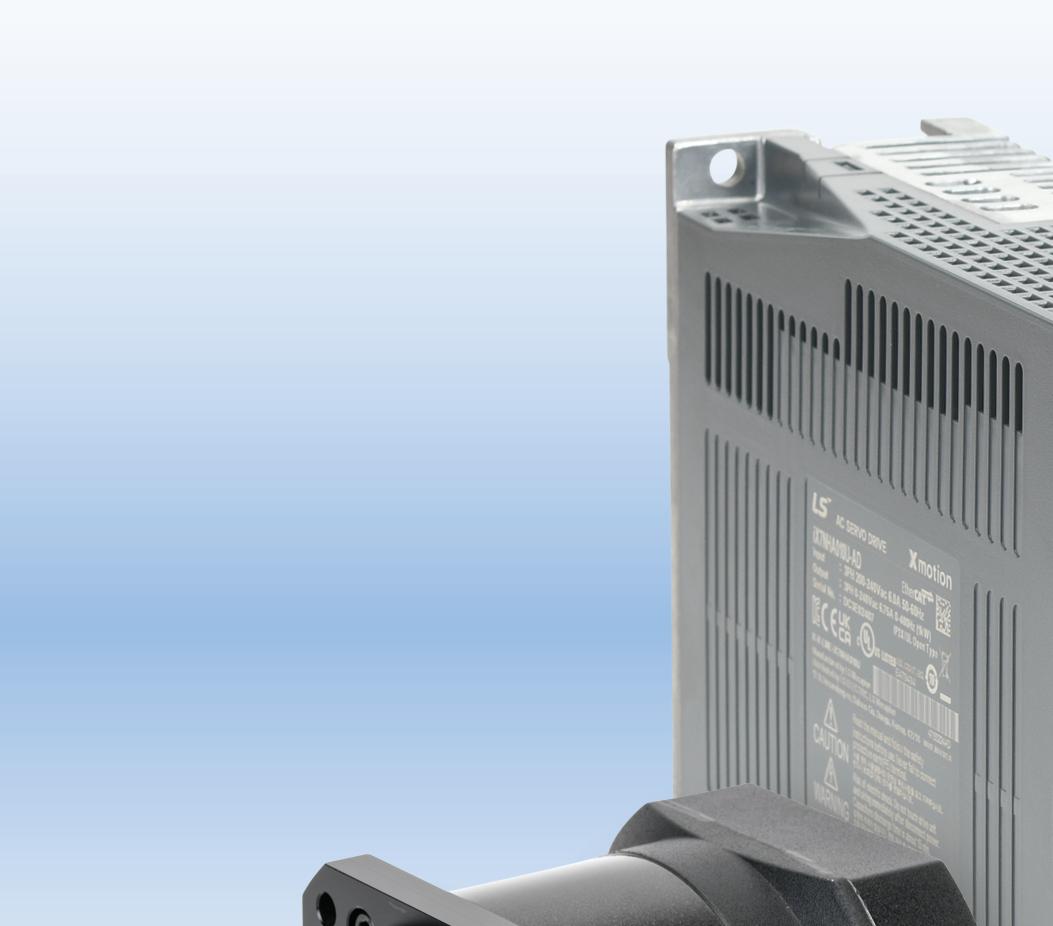
Starting at $964.00 (100W system with cables and I/O breakout)


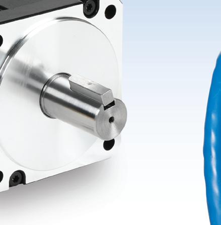
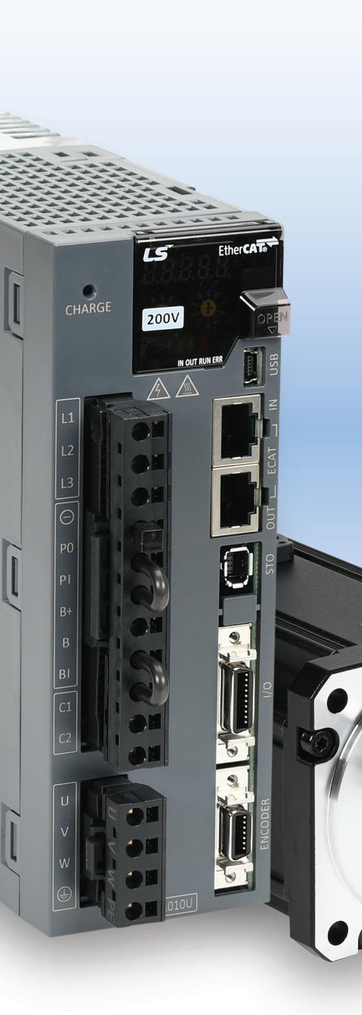
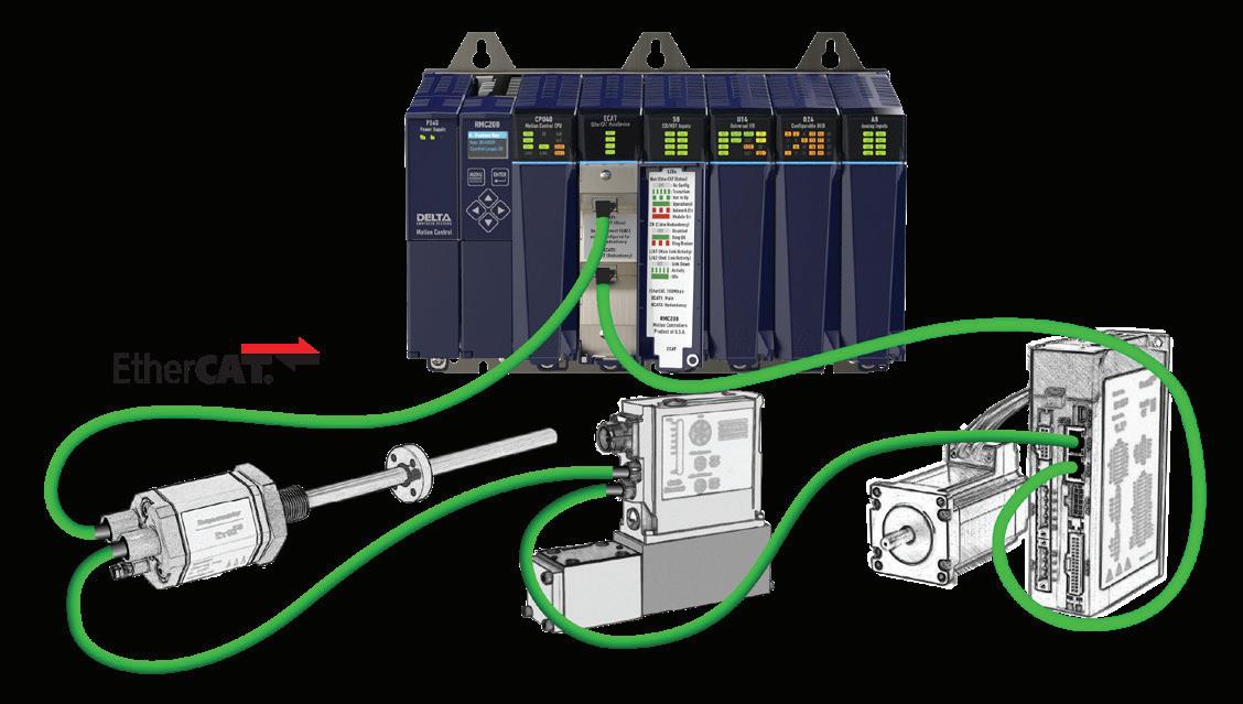
LS Electric iX7 servo systems offer advanced multi-axis motion control along with EtherCAT networking. The EtherCAT protocol provides extremely fast, real-time, deterministic, and synchronized communication for high precision motion.
• 9 standard servo systems from 100W to 3.5kW
• Multiple input power options:
• 110VAC single-phase up to 400W
• 230VAC single-phase up to 2.2k
• 230VAC three-phase in all sizes
• Use with any CANopen over EtherCAT (CoE) compatible PLC/host controller or one with ModbusTCP capability
• Fully digital with 1kHz velocity loop response
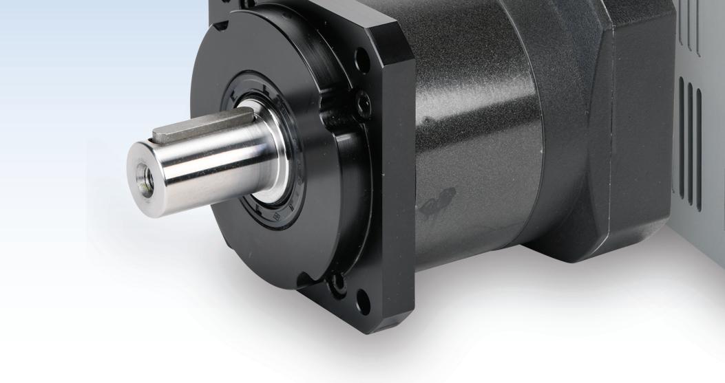
• Matched gearboxes available for all systems in 5:1. 10:1, and 20:1 ratios
• 45-day money-back guarantee
• One-year warranty
EtherCAT® is a registered trademark and patented technology, licensed by Beckhoff Automation GmbH, Germany.

Use our LS Electric Servo System Selector Tool to size your system, and to specify all the required and optional accessories for YOUR application. Get ALL the parts you need on the first order!
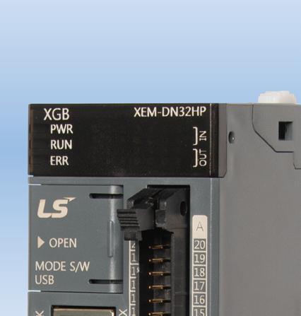
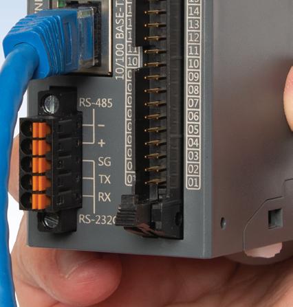


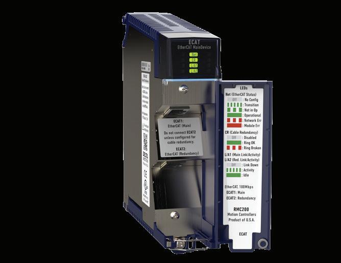
Need an EtherCAT controller?
LS Electric® XGB PLC CPUs starting at $279.00 (w/FREE software)
The LS Electric XGB PLC controls up to 16 axes of EtherCAT® motion with several positioning methods including linear, circular, helical, and ellipse interpolation. Seven homing routines are also available and the FREE software offers a graphical interface so you can see the motion in action! The XGB series PLC is a perfect control solution for:
• Palletizers
• Pick-and-place applications
• Rotary tables
• Flying cutoff systems
PLC
• Precision machining tools
• Automated welding systems
• and much more
PLC systems with a 4-axis EtherCAT positioning module starting at $629.00 (not including servo systems)


2025 marks the 15th year that Design World has published a Motion Systems Handbook special issue.
readers informed on not just the basics of motion control but also the major trends in the industry impacting their day-to-day work as well as the ways in which design engineers are solving motion challenges in unique ways.
In this year’s handbook, executive editor Lisa Eitel’s story summarizes this broad swath of components that comprise motion control systems — plus highlights some non-industrial consumer and entertainment-based applications where motion control has recently been implemented. These newer applications are enabled by the ongoing evolution of mechanical drives as well as electronics and software.
In robotics especially we see the perfect convergence of motion components; from motors and gearing and actuators to controllers, drives, sensors, software and programming.
The first one was way back in 2011. In that first handbook, the focus was on the basics of individual components used in motion systems, with subsequent editions emphasizing selection criteria as well as interesting applications. The detailed components were a broad array that assemble to make motion possible. These include electric motors (ac and dc motors, stepper motors, servo motors, and so forth), actuators, gears, different types of mechanical drives (belts and pulleys, chain drives, screwbased drives), and the electronic side of motion systems including controllers, drives or amplifiers, and feedback devices along with electrical cabling for power and signal transmission.
From that first edition sprang other special motion issues. Design World now has four motion issues throughout the year. Along with the Motion Systems Handbook is the Power Transmission guide, covering the more mechanical side of motion systems, a special fall edition highlighting unique motion applications, and a spring edition devoted to the latest trends impacting the motion industry.
Together, these four special issues demonstrate Design World ’s ongoing commitment to being a leader in the motion control industry; keeping our
From the start, we here at Design World have made a commitment to be the go-to for motion control and motion system design. We strive to make each year’s handbook the most beneficial to you, our readers, and we hope that you find this an excellent resource for your design-engineering needs.
Through all of these developments, we Design World technical editors cover it all to keep you informed and ready to deploy the latest technology for solving day-to-day design challenges.
As your go-to resource, you’ll find the latest in product information and industry news at motioncontroltips.com and linearmotiontips.com as well as motion-product information and much more at our flagship site designworldonline.com •


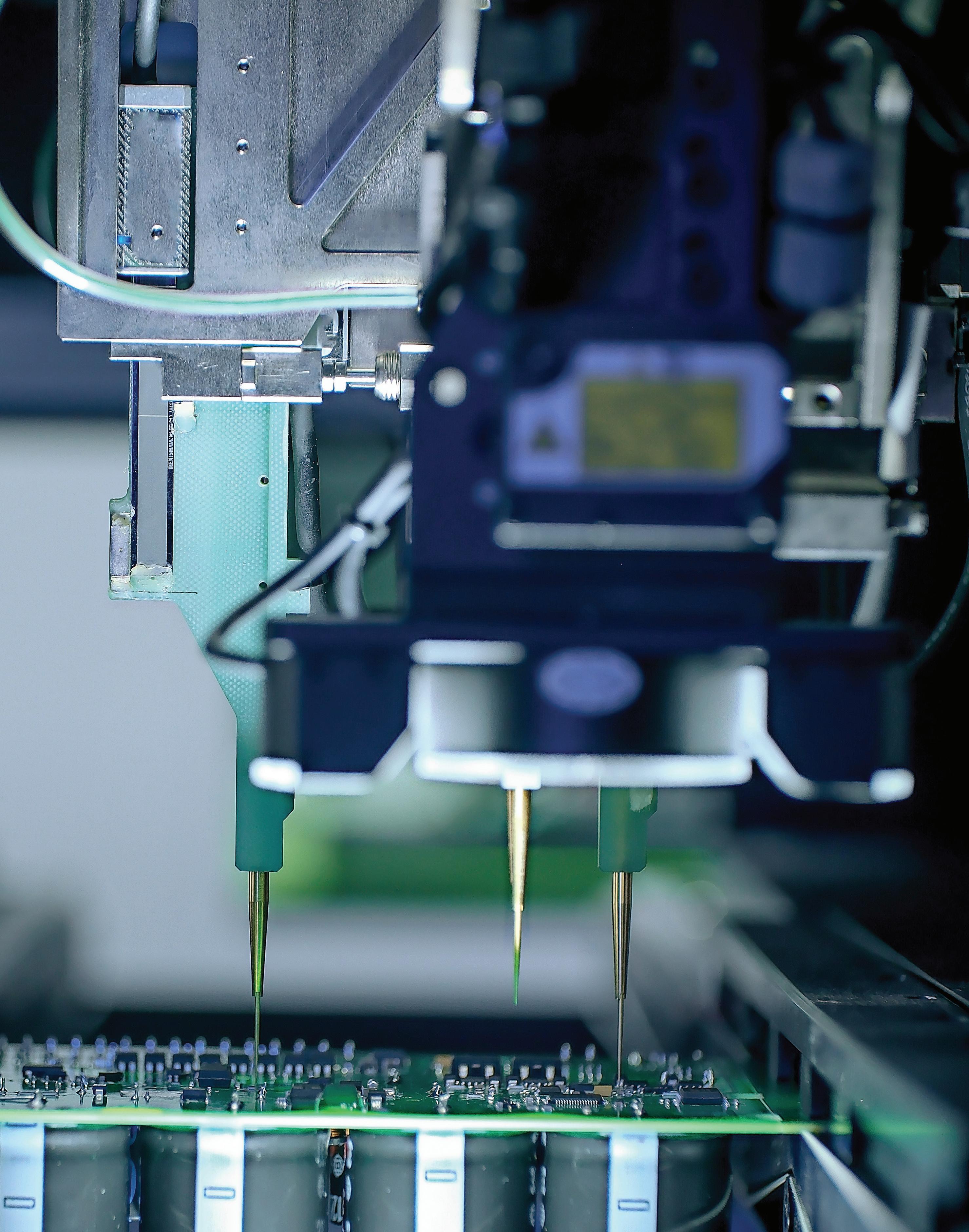
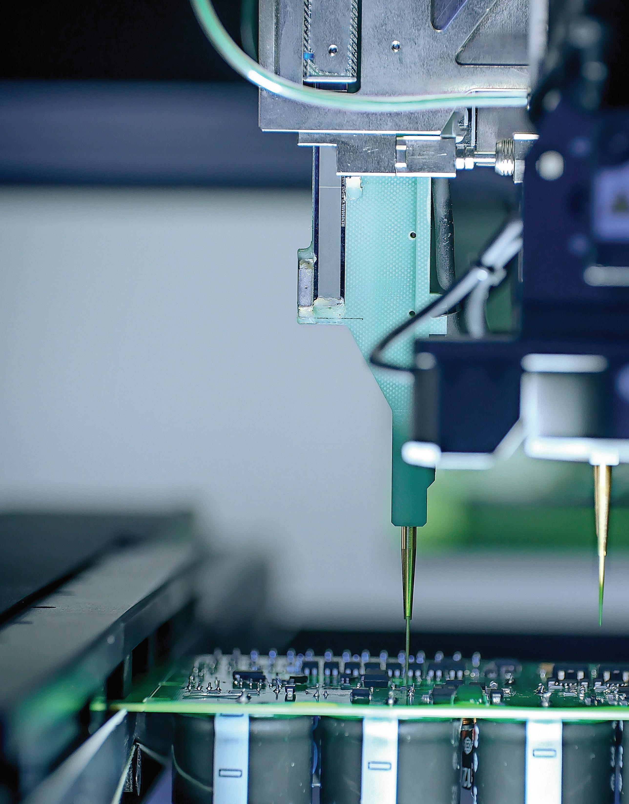
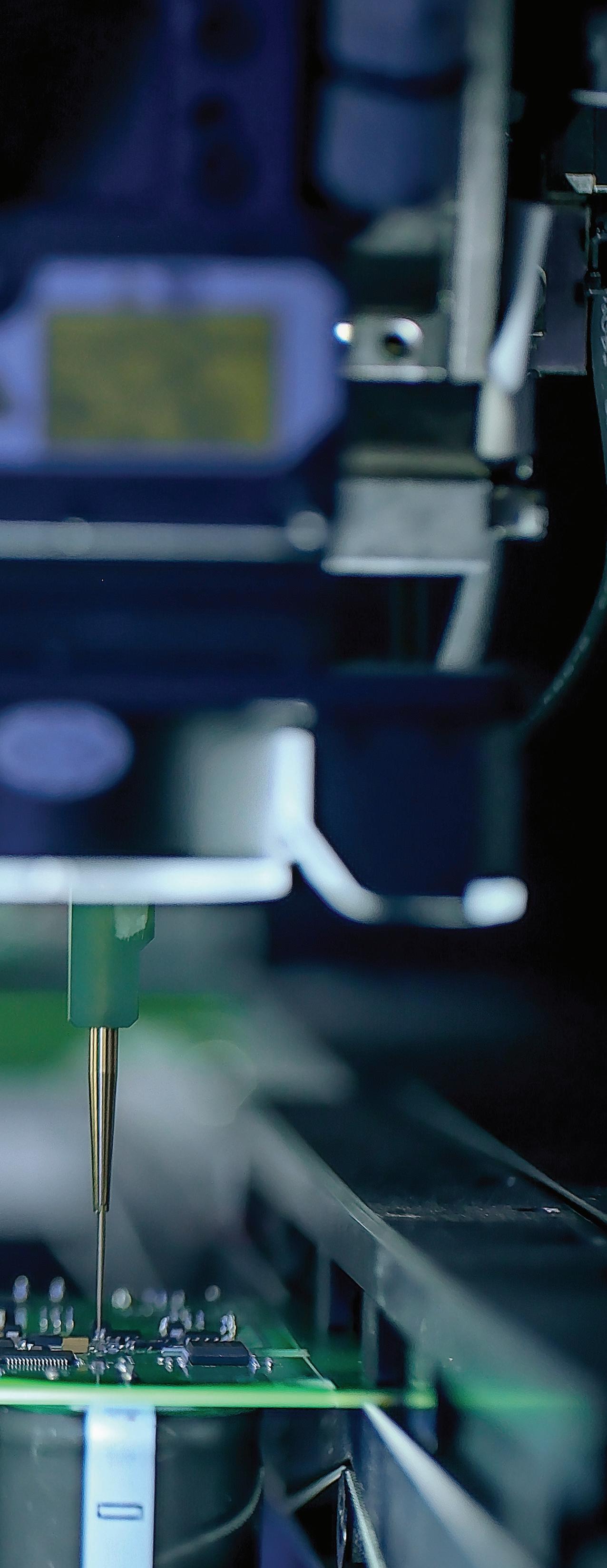
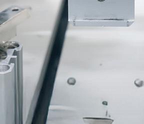
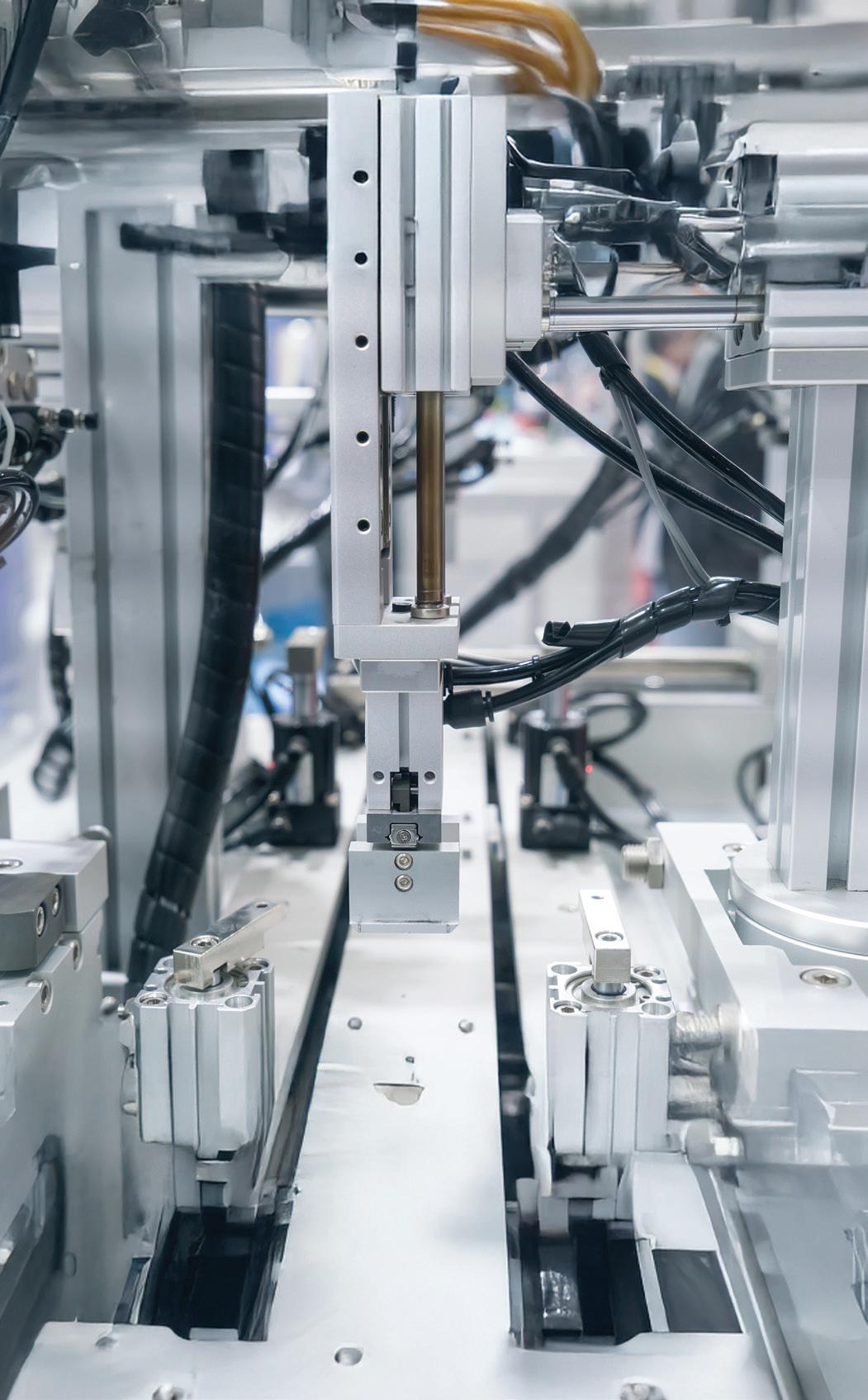
Precision feedback on the vertical axis of this semiconductor-manufacturing machinery ensures accurate circuit-board assembly.
are machine builds for which there’s emphasis on raw torque (or force) and speed.
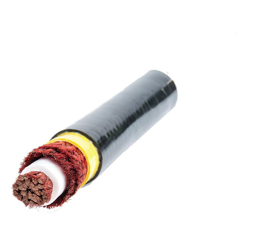
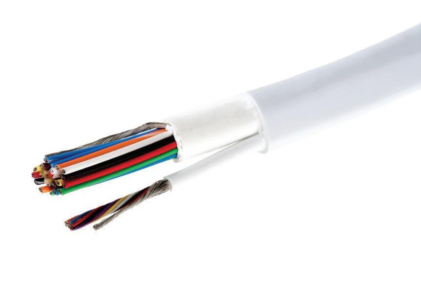
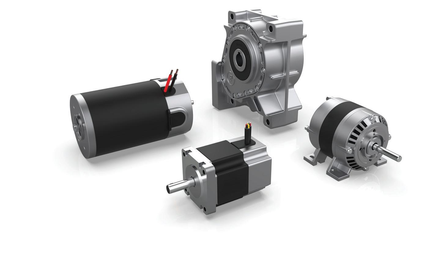
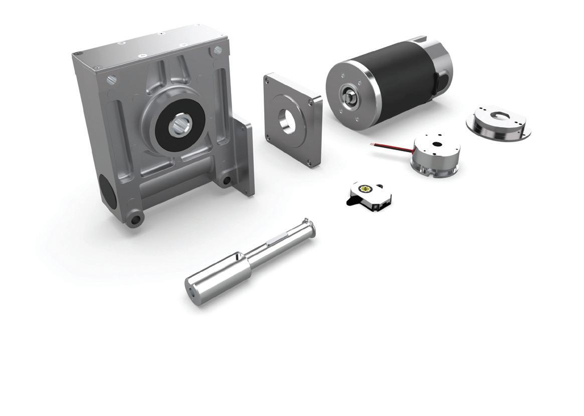
All motion systems are electric-motor-driven designs built around two kinds of components. Mechanical power-transmission components include gears and gearsets, kinematic linkages, belt and pulley sets, chain drives, linear screws, rotary bearings, slides, and guides. Electrical and electronic motion-control components include electric motors, motor drives, the electronics known as motion controllers, sensors, pneumatics (which after all rely on electrically compressed air for operation), and connectivity components such as cables, network switches, and power supplies.
are machine builds for which there’s emphasis on positioning and controlled motion profiles defining the speeds, accelerations, jerk, speed-torque profiles, and homing routines of the machine’s various axes.
The motion industry often uses the term powertransmission designs to indicate machine builds for which there’s emphasis on raw torque (or force) and speed — and domination of the build by the mechanical components. The motion industry often uses the term motion systems to indicate machine builds for which there’s emphasis on positioning and controlled motion profiles defining the speeds, accelerations, jerk, speedtorque profiles, and homing routines of the machine’s various axes.
Both design types are at the heart of myriad consumer products, office automation equipment, medical devices, laboratory automation equipment, and (in the industrial space) discrete factory automation. In fact, this is yet another distinction to be made.
Discrete factory automation differs from the other type of factory automation — that associated with process or analog automation. Discrete automation (not to be confused with discrete motion control) involves the working, machining, assembling, testing, capping, wrapping, packaging, labeling, counting, scanning, and transporting of separate (discrete) workpieces or other individual products. Each workpiece might be subject to several different operations before completion.
Automotive manufacture, electronics production, automated warehousing operations, and packaging are all discrete automation industries.
In contrast, process automation involves vats of liquids, uninterrupted systems of fluids, and other batches subject to continuous chemical reactions, temperature controls, metering, and flowing operations that are generally difficult to stop and start. Process automation industries — in which these types of operations dominate — include mining, energy (via both coal and nuclear), oil and gas, food processing, pharmaceutical and chemical manufacture, glass and
ceramic production, plastics, textiles, and wood and paper.
Motion system designs are associated with discrete automation to deliver on the precise placement and transport of discrete workpieces or other individual products.
Many of the core linear powertransmission technologies used in today’s modern industrial-automation applications have been in use for 50 or more years. However, their design and manufacture (as well as their modes of integration) have continually advanced to allow increasingly sophisticated actuation capabilities and applications. Complementing these modern iterations of mechanical components are motion controls and feedback devices (both electronics hardware and software) with unprecedented functions and flexibility.
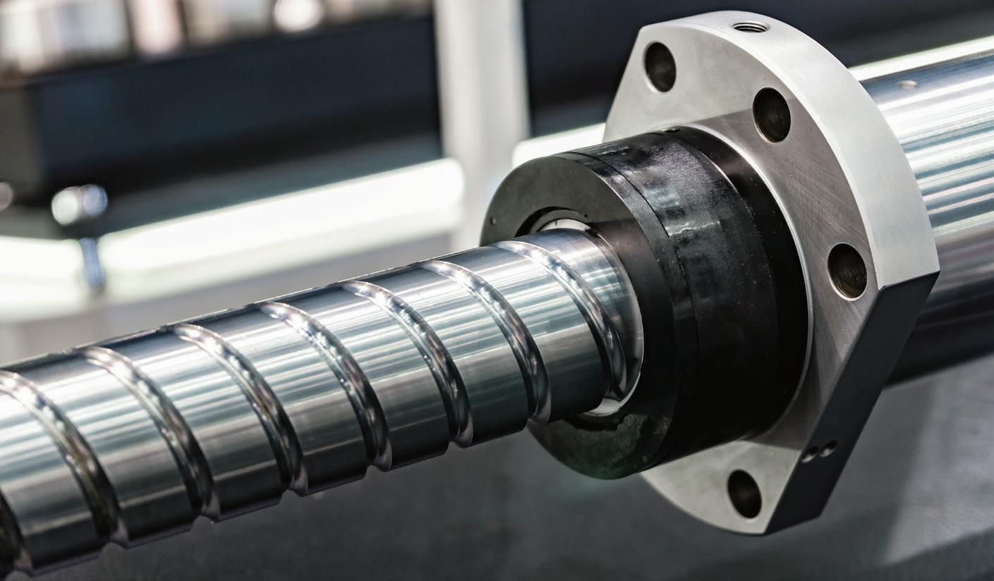
Consider the various adaptations of mechanical screws. Except for pneumatic, solenoid, piezo, electrohydraulic, and linear-motor designs, the core of all linear-motion systems is a rotary electric motor paired with some mechanical rotary-to-linear device. The latter converts the high-rpm rotary motion motor output into a linear stroke. More common options include ballscrews; roller screws (including planetary and differential types); leadscrews and (especially for vertical applications) jack screws; and belt drives, chain drives, and pack-and-pinion sets.
More exotic power-transmission

components for linear motion include rigid-chain assemblies that lock in one direction to push loads; slider crank, disc-cam, and walking-beam drives; cylindrical-cam and set axis mechanisms; and traction drives and skewed-roller rds.
Confusing matters is that sometimes these rotary-to-linear mechanical devices are themselves called drives or (worse yet) actuators. Design World reserves the term actuator to mean those fully integrated “muscles” that include a motor with or without gearing, coupling if applicable, rotary-to-linear component, and (in most cases) some frame and linear component to bear or support and guide the translated load. Read more by scanning the QR code.
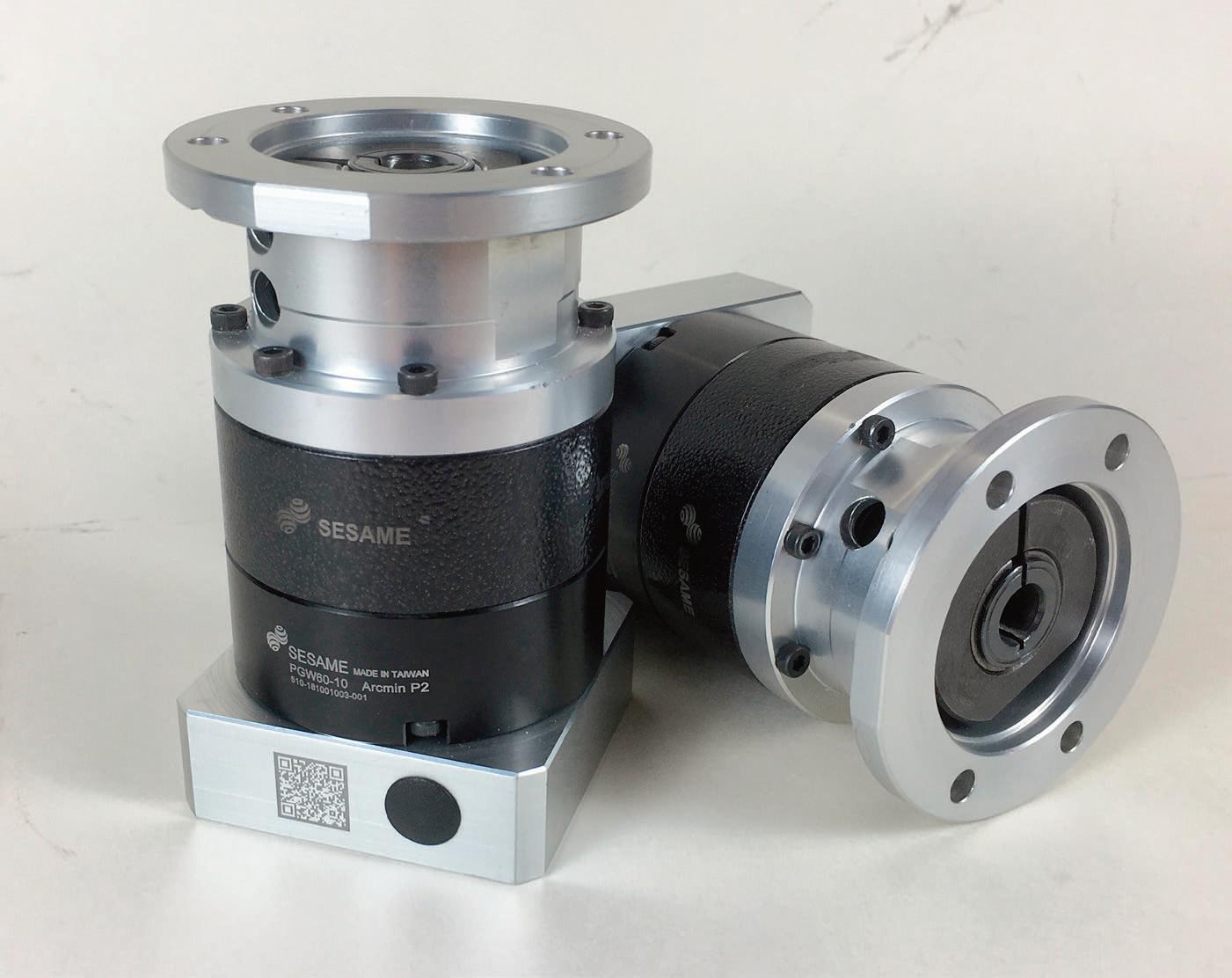
Rotary bearings are also everywhere in motion — in gearboxes, motors, pulleys,

Access the latest primers on ballscrews and roller screws here.
and myriad other machine locations involving a rotating shaft that needs lowfriction radial and axial load support. The two major rotary-bearing classifications are rolling-element rotary bearings and plain rotary bearings.
Plain rotary bearings in motion designs have engineered inner surfaces to ride (through sliding) on round shafts with minimal friction while bearing the load at that location on the axis. Usually, their structure only allows support of axial loading. Plain rotary bearings are sometimes called plane bearings (for their single-plane operation) … and “plain bearings” is usually a catchall phrase that also includes related designs called:
• Journal bearings from the Old French word for a day’s journey or work — in this case, over a hardened shaft journal
• Bushings from the Old Dutch word for metal lining … often indicating an engineered plastic or soft metal or cylinder with or without the need of lubricant for load bearing
• Sleeve bearings all having their own adaptations and applications.
Key plain-rotary-bearing advantages include simplicity, reliability in wet locations, and cost-effectiveness.
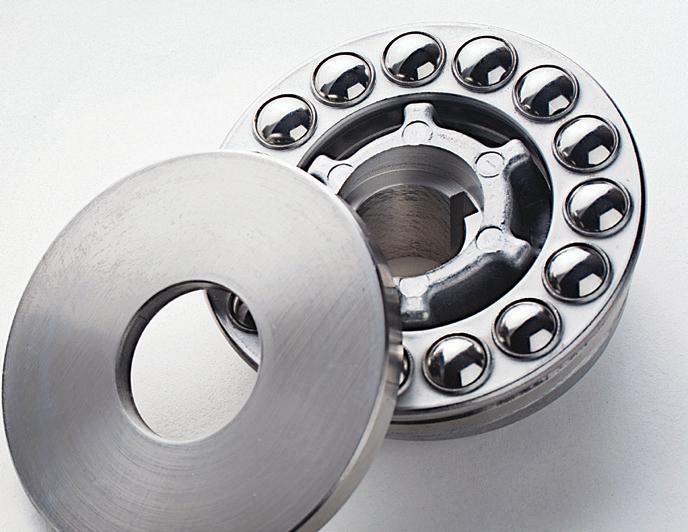
In contrast, most rolling-element rotary bearings include an inner ring with an OD raceway, an outer ring with an ID raceway, and an array of spherical ball rollers (not to be confused with balland-socket-style spherical bearings) or cylindrical rollers sandwiched between them. The array of rolling elements ride through rolling on the two bearing-rings’ raceways. Their ring structures and roller shape can be designed to allow support of axial, radial, and combination loading.
Key rolling-element rotary-bearing advantages include long service life and the ability to bear heavy loads on exceptionally high-speed axes. Read more by scanning the QR code.
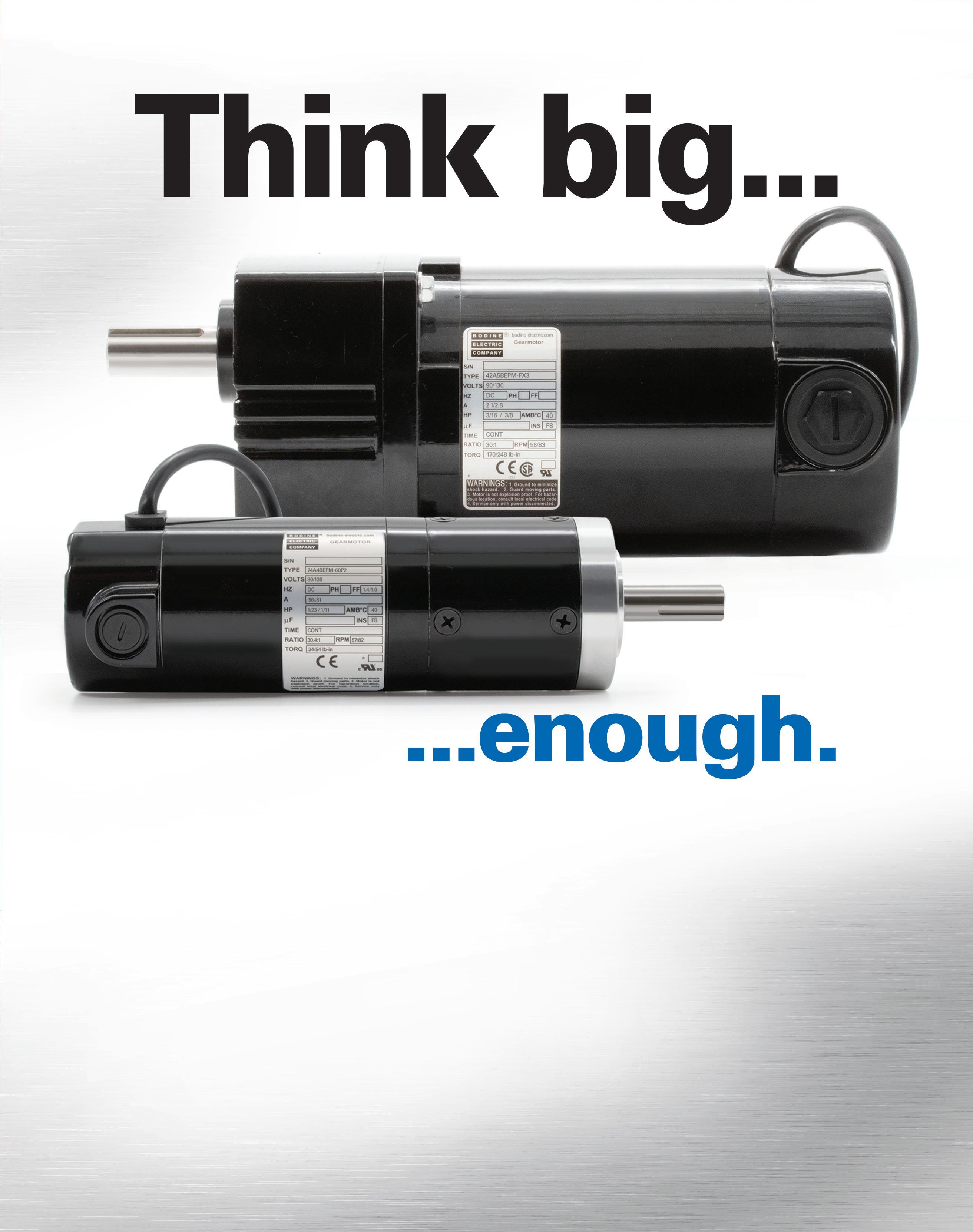
If your application runs intermittently, you may be paying for power you don’t really need. Think outside the nameplate! Let the engineers at Bodine Electric Company help you find a gearmotor that delivers the perfect balance between size, performance and economy.

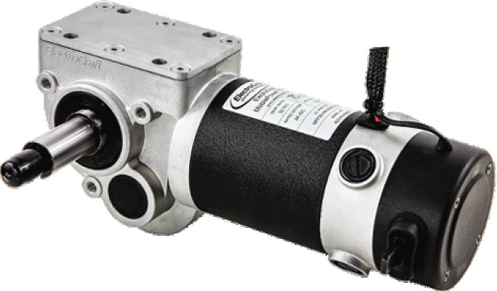
Consider a mobile satellite antenna mounted atop a TV news van. The gearmotor is stressed for a short time while it positions the dish, and then turned off for a long time during the broadcast. The designer of the antenna could have chosen the larger gearmotor shown above, with a continuous torque rating that matches their requirement, but they instead chose a smaller Bodine planetary gearmotor for its peak torque rating.
Learn how to size a gearmotor big enough for your next project. Read the Engineer’s Guide to Selecting the Best Gearmotor.
Consider a final technology — that of industrial clutches and brakes. Those used on the electric-motor-driven axes of various machine designs differ from those used in automotive applications as well as those for large-scale processes driven by combustion engines and other non-electric-motor prime movers. Industrial brakes (regardless of type, size, or engagement method) provide three basic functions: They slow loads, they stop loads, and they hold loads stationary.
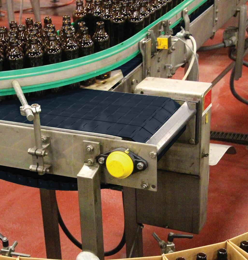
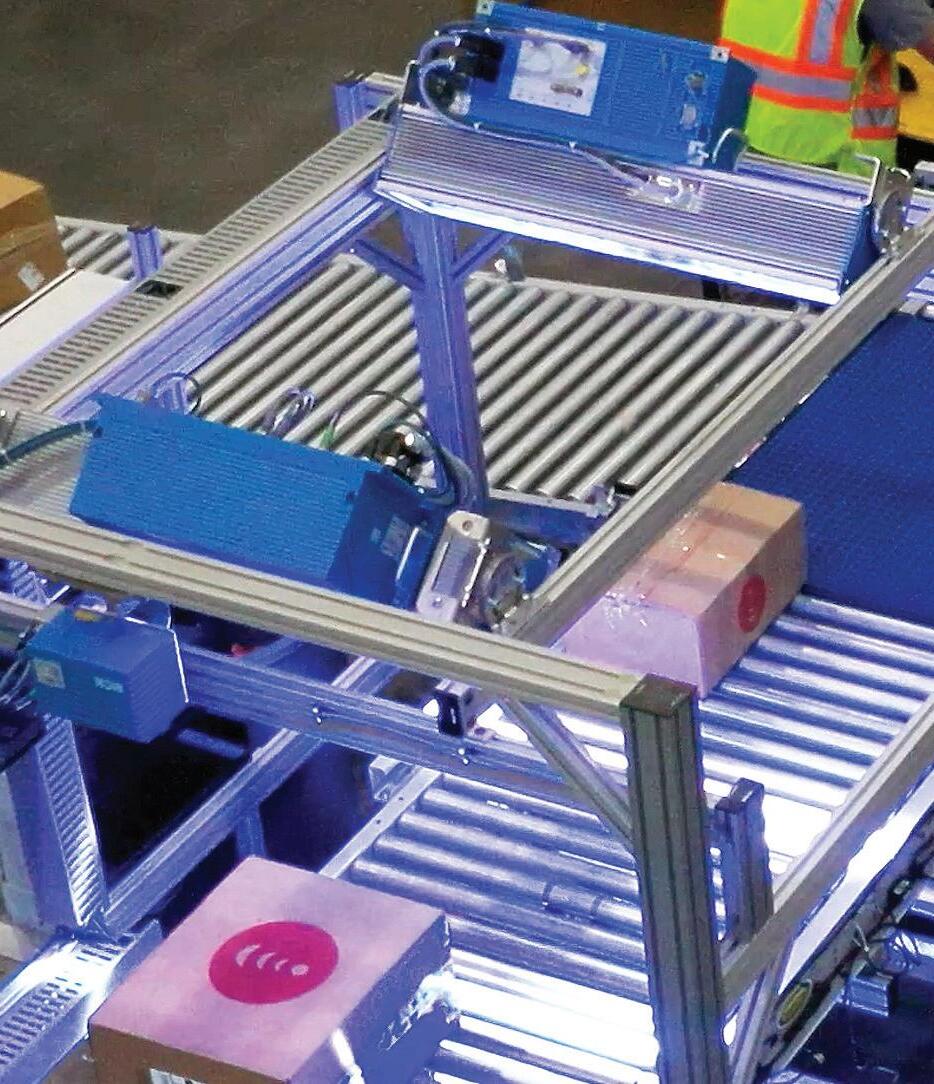
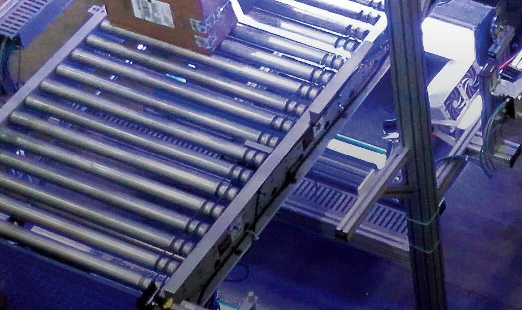
Some brakes serve only one of these functions while others can stop, slow, and hold. For example, in an automated warehouse, two conveyors might carry product that needs to be merging into one stream. Here, brakes on one conveyor can help properly sequence product — and prevent these discrete items from colliding with the products riding on the other conveyor.
In the same automated warehouse, another conveyor might transport boxes into a label-applicating station. Here, a brake stops and holds the discrete items while the station applies its labels. Then the brake releases the box to let it travel onward.
In a printing press, paper web from an unwinding roll feeds into a main machine. When that machine slows, a brake on the unwinding roll may in turn slow the roll rotation so that web speeds (and tension) remain consistent with that of the printing machine. Here the brake won’t stop the roll — only unwind the roll at a slower pace.
On a machine tool having a vertical axis, electric motors may raise and lower the load. The problem is that if the motor is turned off (or worse, loses power during a power failure) a brake can protect both personnel and the machine by safely holding the load in position.
Lastly, consider the basics of industrial clutches. Clutches (no matter their size or type) all perform one basic function — they connect and disconnect a prime mover (in this context, an electric motor) to and from the load. This is true of a tiny 3-lb clutch one inch in diameter on a piece of mail-sorting equipment that connects and disconnects a sub-fractional motor to a nip roll. It’s also true of a 15-in.
clutch delivering (and disconnecting) 1,200 ft-lb of torque to a combine header. It’s even true of a massive 36-in. clutch transmitting 6,000 ft-lb of torque on a draw-works cable reel on a rotary oildrilling rig.
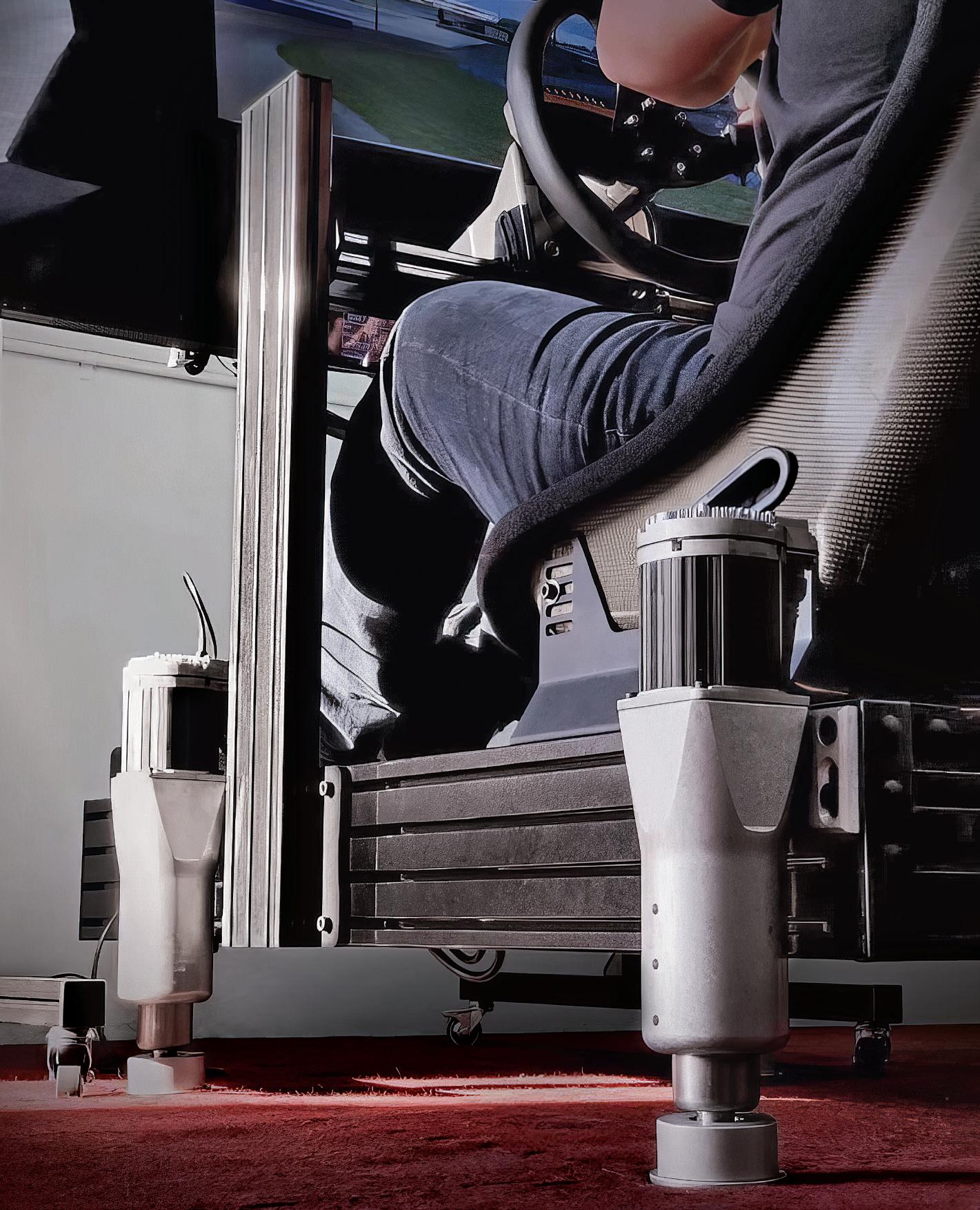
Once a niche hobby, simulation or sim racing has attracted a growing number
of enthusiasts seeking virtual motorsport experiences. The popularity surge has fueled demand for professional-grade simulation hardware that accurately replicates real-world racing-vehicle physics, track environments, and driver tactile feedback.
Automotive, truck, and flight-simulator R&D and build integrator Sigma Integrale serves this market with DK-series motion systems. In fact, the company’s patented motion-vehicle technology lets simulator suspension systems move according to the inputs experienced by the driver in virtual environments. Sigma engineers have built custom, full-motion vehicle simulators

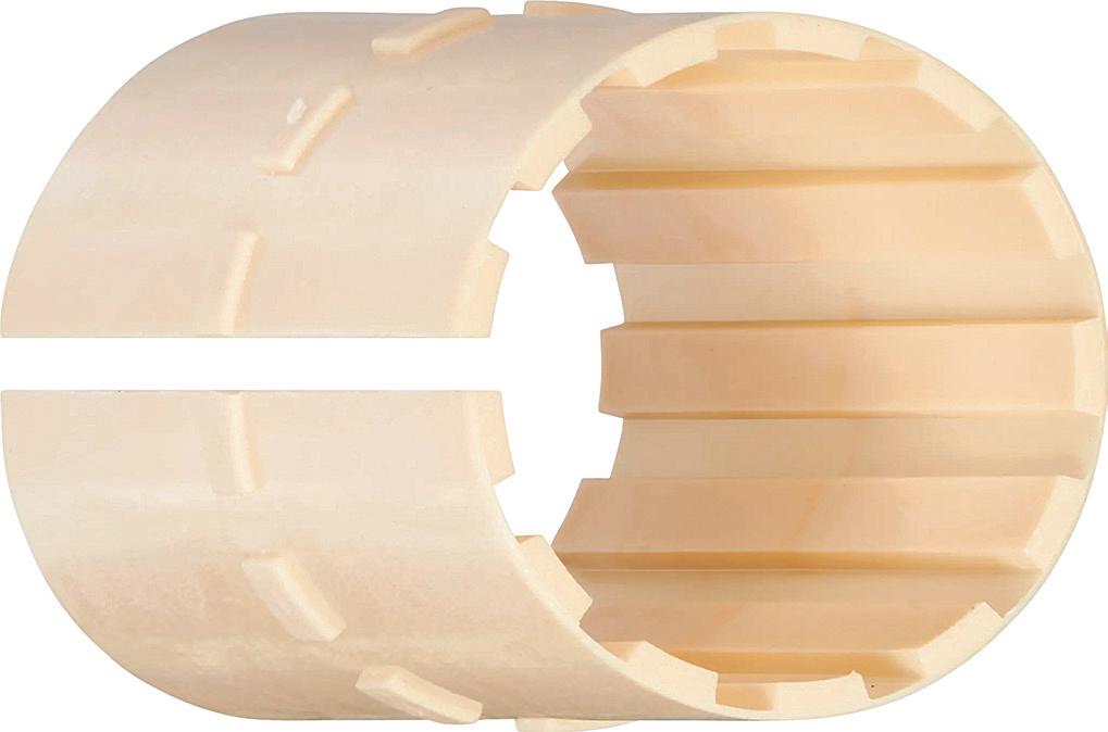
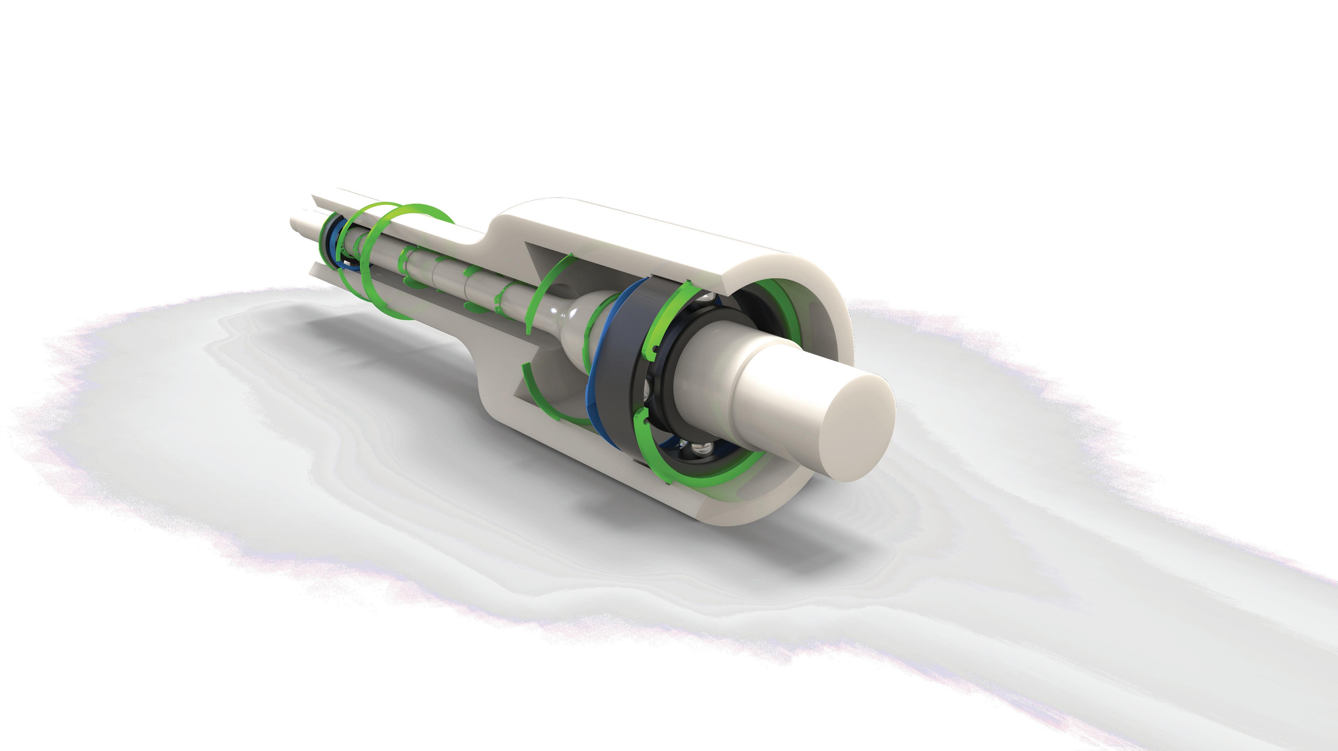
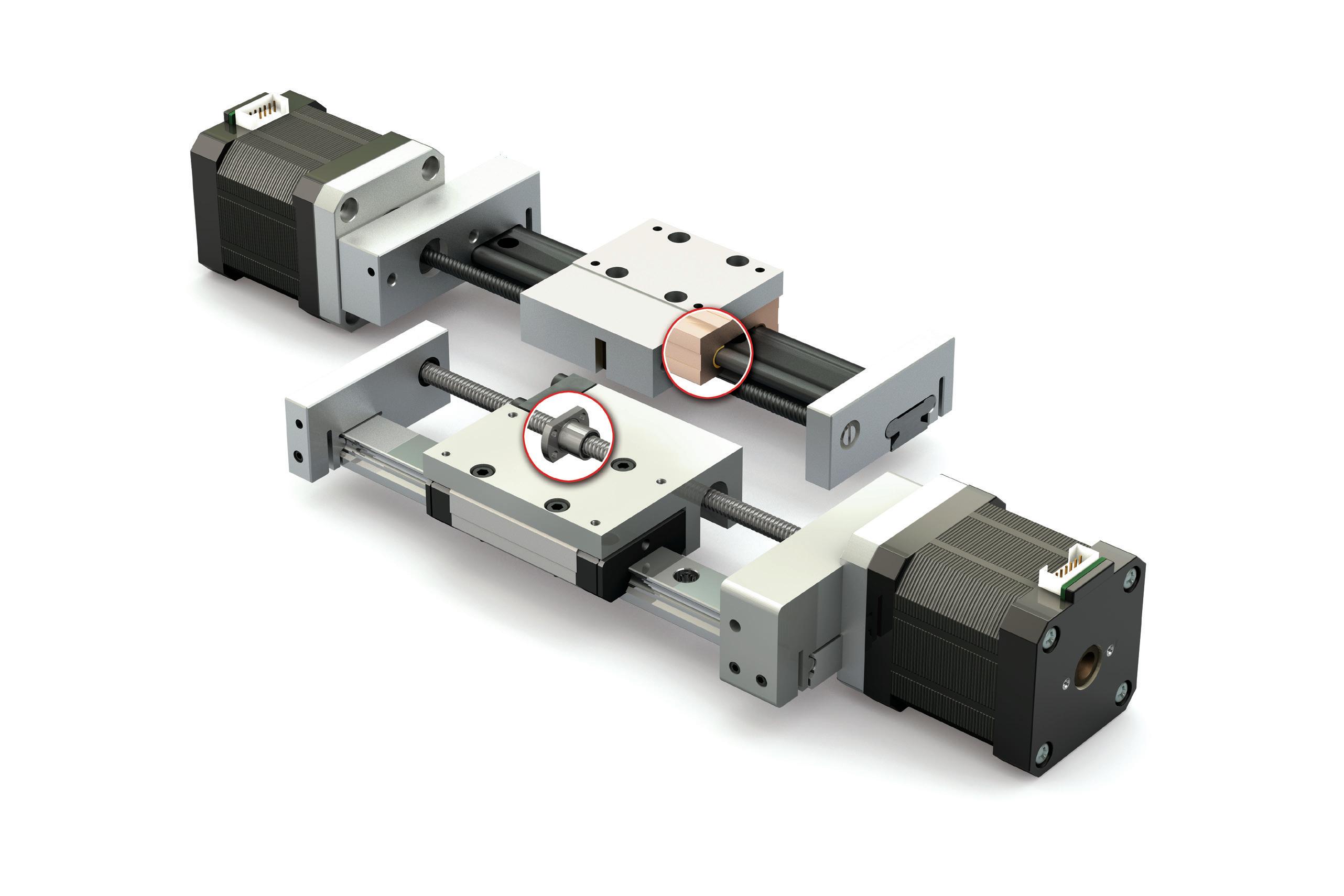
Made from high-performance polymers embedded with solid lubricants, igus liners allow smooth linear motion without external lubrication. Different liner materials are compatible with aluminum, steel, and stainless steel shafts. Plus, the drylin liner supports easy installation and replacement. Grooves securely lock the liner into the housing. Split-housing options are available for easy assembly and quick replacement of the liner if necessary.
for Dodge, Fiat, Volkswagen, and Alfa Romeo. They’ve also re-engineered suspension components, instrument gauges, controls, visual displays and sound systems in everything from go-karts to semi-trailer trucks.
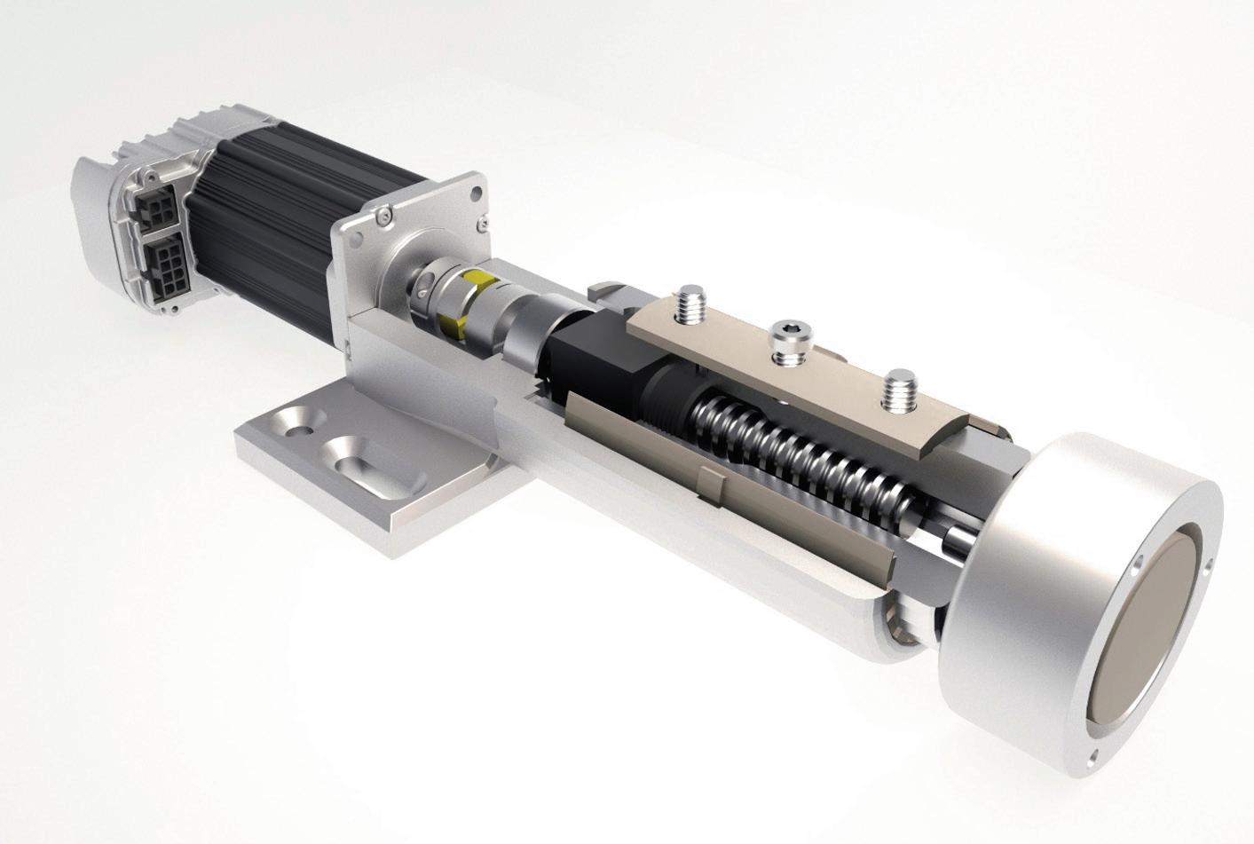
In a recent DK-series design, a top objective was getting maintenance-free linear bearings for a piston mechanism that lifts a simulator frame up and down to mimic driving conditions. More specifically, a Sigma DK6+ system (replicating suspension travel and environmental pitch and roll of dirt ovals and off-roading) features four motorized actuators with 6-in. travel. They’re compatible with any aluminum-extrusion sim chassis via mounting plates.
All DK products feature an aluminum housing and steel piston machined in the U.S. from billet raw materials. Electricmotor torque transmits via a coupling to a ballscrew. An igus JUIO-01-32 drylin liner lets the ∅2-in. steel piston slide in and out of the aluminum housing while providing side-loading support. An anti-rotation slider 3D-printed by igus prevents the steel piston from rotating inside the aluminum housing.
Sigma engineers ultimately selected the igus JUIO-01-32 drylin liner because it doesn’t need external lubrication — a significant advantage for a consumer product used in homes where users don’t want to deal with greasing. The igus JUIO-01-32 uses offers dry-running linear motion using tribopolymers for grease-free operation. Known for their selflubricating properties, igus liners are manufactured from highperformance polymers embedded with solid lubricants. This composition allows for smooth linear motion sans oil or grease, as the embedded lubricants are released during movement. What’s more, the drylin liner will never corrode and can operate in environments with dirt and dust. The selfcleaning nature of the liner prevents particles from adhering


At Regal Rexnord, we are harnessing the power of one to transform innovation in your operations. By bringing together industry-leading engineering and best-in-class brands, we deliver both standard and custom solutions - all from a single source.
Our conveyance systems, predictive maintenance platforms, condition monitoring hardware, servo motors, and precision drives are designed to optimize speed, enhance precision, and ensure unmatched reliability.
One Supplier. One Vision. One step ahead. Learn how our engineering excellence and cutting-edge technology drive innovation forward.

Learn more at rrx.link/packaging-machinery
to its surface, so operation is smooth and reliable. Contact between the guide and shaft reduces surface pressure is continuous and larger than that of traditional recirculating ball bearings, so operation is quieter … a particularly beneficial characteristic when sim rigs operate in homes.
The drylin materials are lightweight and corrosion resistant, making them suitable for various applications. The use of materials such as aluminum and carbon fiber for the shaft guides enhances system resistance to corrosion. These polymer liners are lighter than metallic alternatives, and reduced need for lubrication and


maintenance trims overall cost.
The igus drylin liners provide several benefits to Sigma’s DK motion systems. Their resistance to wear and environmental factors contributes to the system’s durability and long service life — even under continuous use and high side loading. Sigma engineers have observed that the igus products hold up well to years of use and abuse sans issues. The liners have not failed even in cases with rougher piston finishes causing excessive wear.
“We’ve used igus drylin liners in motion systems for years and have never had a part failure or a return related to the liner,” said Sigma head of engineering Howard Lin.
“They handle immense load and side pressure. Honestly, we expect them to need service at some point, but they never do.”
The igus liners take a lot of abuse in a dynamic application and just keep performing consistently, added Lin.
“After spending a long time developing a suitable linear solution, it was impactful to find an off-the-shelf igus drylin liner that exceeded expectations and became the core of the motion system. We know we’re delivering a fantastic athome simulation experience because of it.”
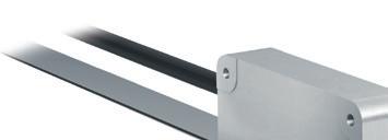
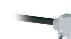
Position, angle and speed measurement
Contactless, no wear and maintenance-free
High positioning accuracy and mounting tolerances


Even though they’ve been around a long time and are fairly simple drive systems, that doesn’t mean they haven’t changed or evolved over time.
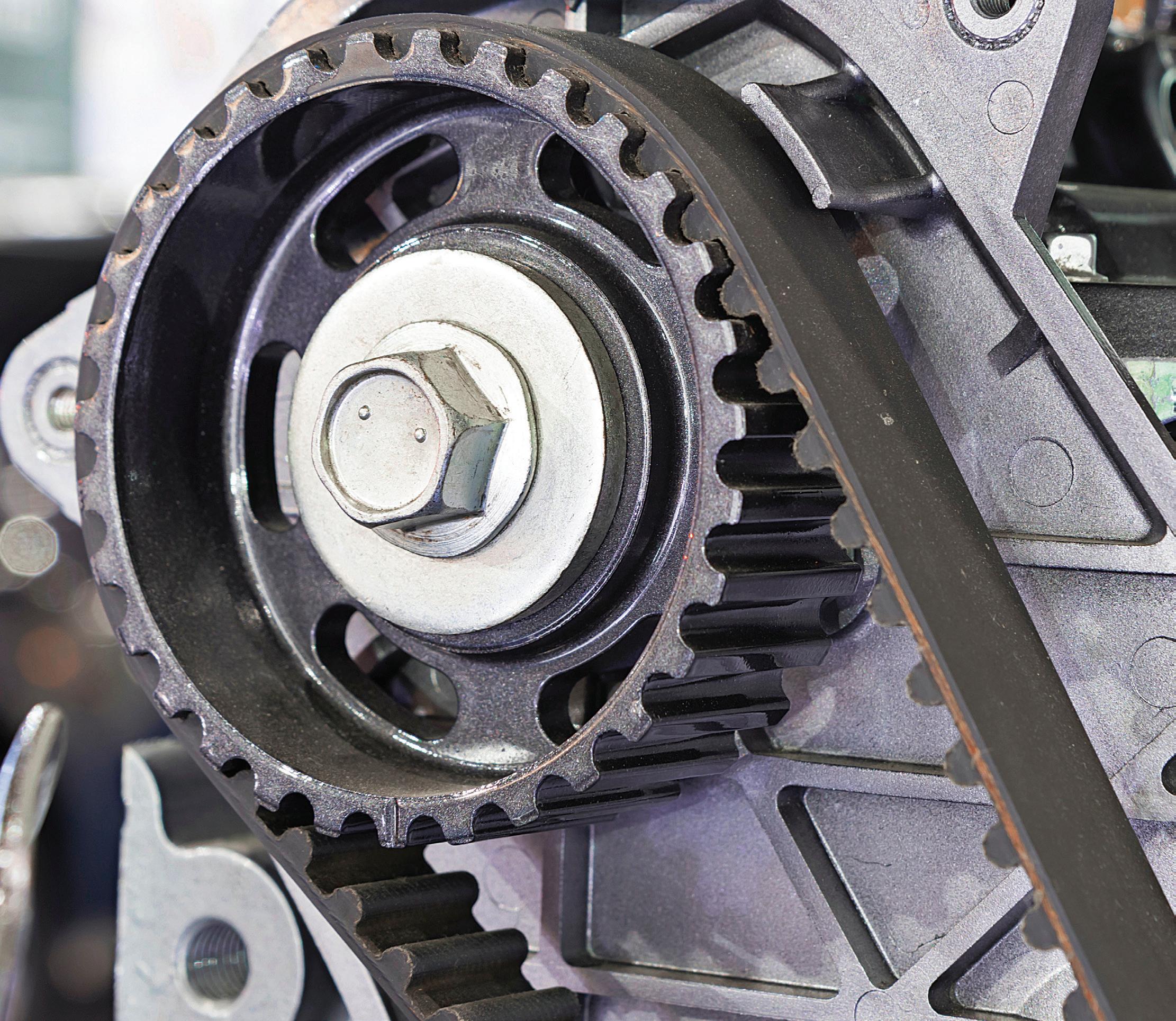
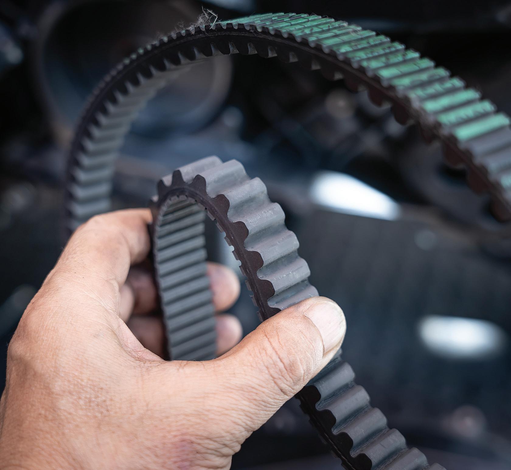
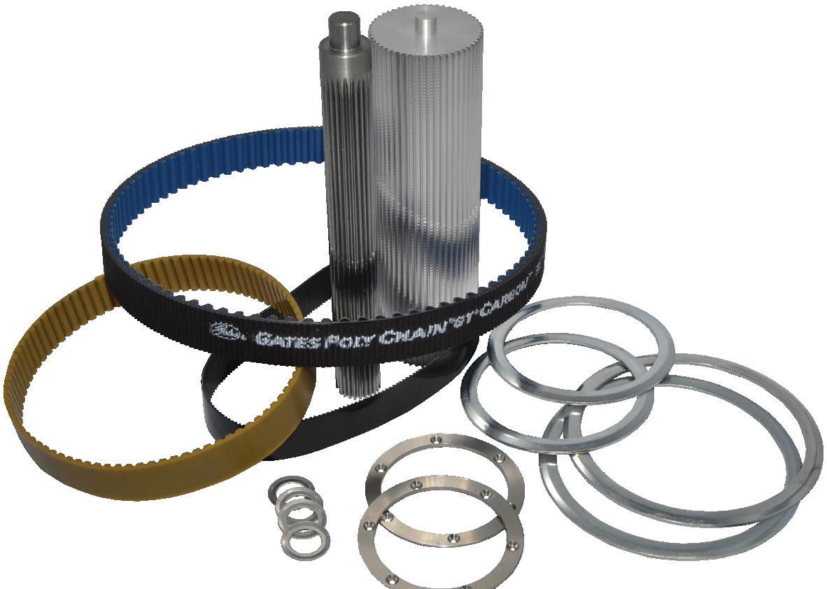
In motion systems, one of the most common and oldest methods of power transmission is the belt drive.
As far as basic operating principles, belt drives have changed little over time. A typical industrial belt drive consists of a belt that wraps around a drive pulley, which is in turn driven by an electric motor. In a typical setup, the belt also wraps around one or more idler pulleys that keep the belt taut and on track.
Engineers choose belt drives in motion systems they’re designing for a number of reasons. For one, modern belt drive systems require little if any maintenance. Plus, they are generally less expensive than other drive options, including chain drives. Belt drives also tend to be quiet and efficient, with ratings of up to 95% or more.
Even though they’ve been around a long time and are fairly simple drive systems, that doesn’t mean they haven’t changed or evolved over time. In fact, belt drives have continued to keep pace with technological improvements as well as with new application uses.
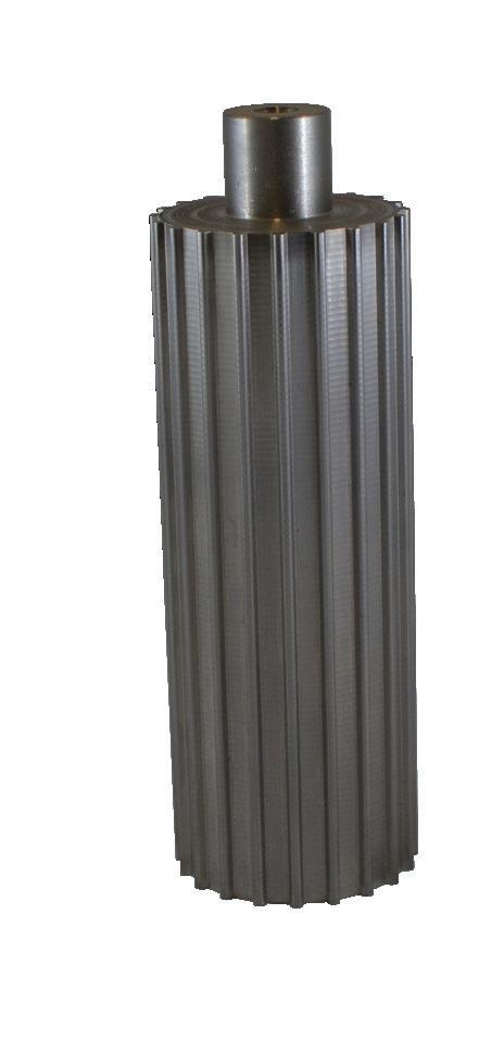
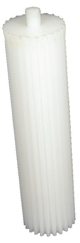
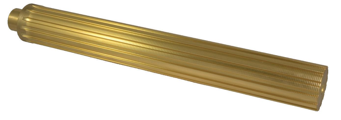
Industrial belt drives in motion designs consist of rubber, engineered


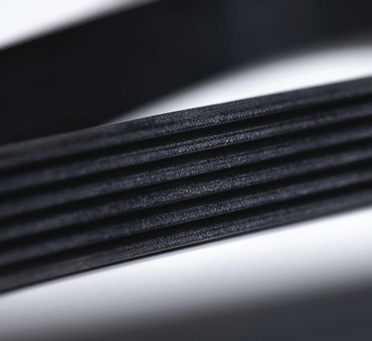
plastic, metal, or (most common) multimaterial belts that wrap around drive pulleys — grooved or otherwise profiled wheels mounted on a shaft. Powered by various motor types, belt drives can drive axes transmitting fractional horsepower to 7,000 hp or more.
What’s more, the tensile members of today’s belts—cords embedded into the belt rubber that carry the majority of the belt load—are stronger than ever. Made of polyester, aramid, fiberglass or carbon fiber, these tensile cords make today’s belt drives thoroughly modern powertransmission devices.
In general, manufacturers describe belts and pulleys with five main geometries. Pitch diameter is the drive pulley’s diameter. Center distance is the distance between the two pulleys’ centers. Minimum wrap angle is a measure of how much the belt wraps around the smallest pulley. Belt length is how long the belt would be if cut and laid flat. Finally, in the case of toothed belts (also called synchronous belts) the pitch is the number of teeth per some length—so a 3-mm pitch means that the belt has one tooth every 3 mm, for example.
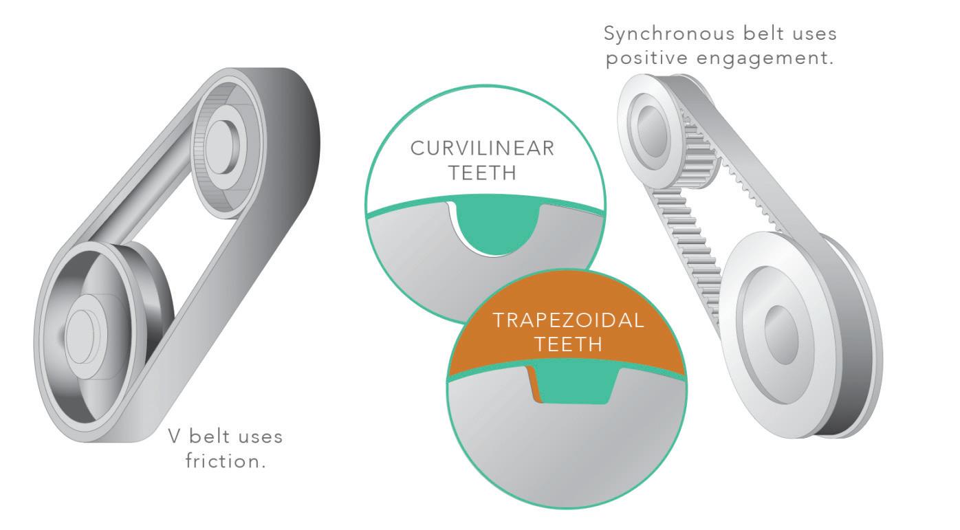
Timing belts — also known as synchronous belts or toothed belts — are most often used in transporting, indexing, and positioning applications where high torque or force transmission and high acceleration rates are required. Unlike V-belts, which rely on friction between


the belt and the pulley for power transmission, timing belts have positive engagement between the belt teeth and the pulley teeth, so the possibility of slip is eliminated. This makes timing belts very efficient at transmitting power and gives them good positioning accuracy.
Belt manufacturers typically offer their own exclusive or patented tooth designs, but even proprietary designs are based on one of three basic profiles—trapezoidal, curvilinear, or modified curvilinear. Each one offers benefits in power transmission, speed capability, or backlash.
Although timing belt tooth profiles are based on just three basic designs, belts with the same type of tooth profile and the same tooth pitch may not be interchangeable. This is due to variations in tooth dimensions between manufacturers’ designs, and in some cases, even within a given manufacturer’s product line.
Belts with a trapezoidal tooth profile are probably the most widely used in timing belt applications, especially for linear positioning and conveying applications. They have good force transmitting capabilities and low backlash. But the trapezoidal tooth shape results in high stress concentrations at the beltpulley interface, which can lead to high wear rates when the transmitted torque or speed is high.
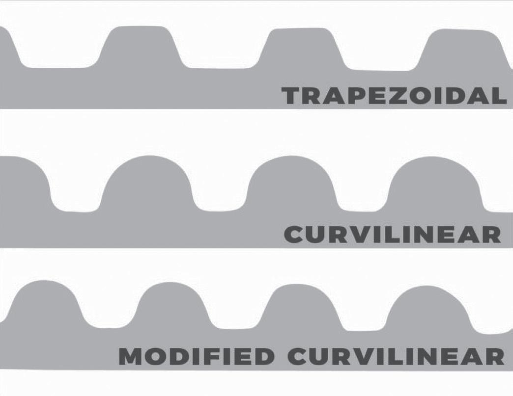
Better load distribution and smooth meshing transitions mean curvilinear teeth are quieter than trapezoidal options. However, curvilinear designs have higher backlash than trapezoidal profiles.
The curvilinear tooth profile was developed to alleviate the stress concentrations found in trapezoidal profiles and improve on torque and speed capabilities. Curvilinear profiles also have a larger tooth depth than trapezoidal designs, so belt ratcheting is less likely. And the smoother transition that curvilinear teeth provide during mesh means these profiles are quieter than their trapezoidal counterparts. The tradeoff, however, is that curvilinear designs have higher backlash than trapezoidal profiles.
The curvilinear tooth profile was developed by Gates, and belts with this profile were referred to as high torque drives (HTD). Although various manufacturers use different names, the HTD designation is still quite common for belts with curvilinear tooth profiles.
curvilinear
Further improvements to the curvilinear tooth profile resulted in the modified curvilinear design. This profile has a smaller tooth depth and a greater flank angle than the original curvilinear version, giving the modified curvilinear design the highest torque and force transmitting capabilities among the three tooth profiles. It also allows the areas of the belt between the teeth to share the load with the teeth that are engaged with the pulley. This means that belts with modified curvilinear teeth are the least likely to experience ratcheting, even under extreme loads, making them common in processing applications that require very high torque transmission at high speeds.


It’s also important to note that belts with a trapezoidal tooth profile are available in both imperial and metric dimension. However, belts with curvilinear and modified curvilinear tooth profiles are available only in metric dimensions. •


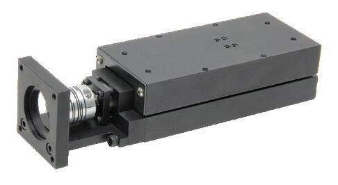
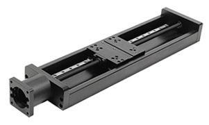
• 6 & 10 mm lead screw and 8 mm ball screw options
• MAX stroke length up to 1000 mm
• Integrated NEMA 17 or 23 motor
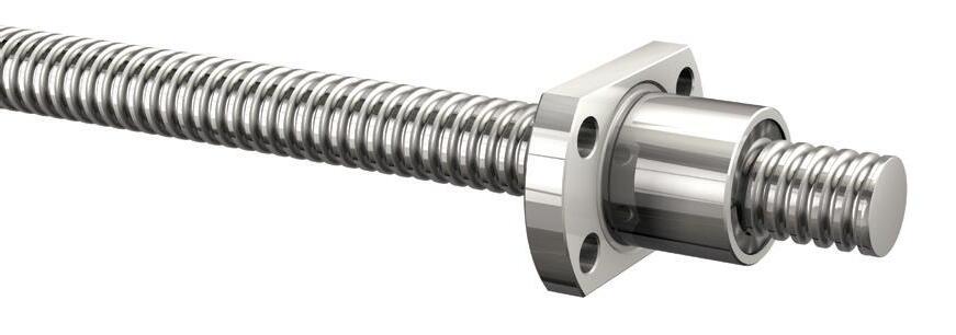
• Metric sizes: 6 x 1, 6 x 2, 8 x 1, 8 x 2, 8 x 2.5, & 10 x 2
• Grades 5, 7, & 10
• Flanged and cylindrical nut configurations
• Lengths up to 1,650 mm
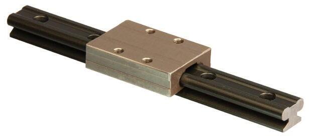
Mini-Rail Linear Guides
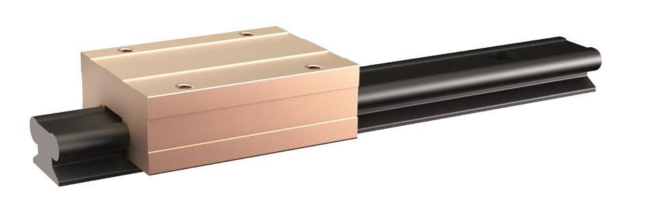
• 5 sizes: 7, 9, 12, 15, & 20 mm
• Self lubricating FreelonGold®
• Withstands vibration & shock
• Rail lengths up to 3,600 mm
• Corrosion resistant

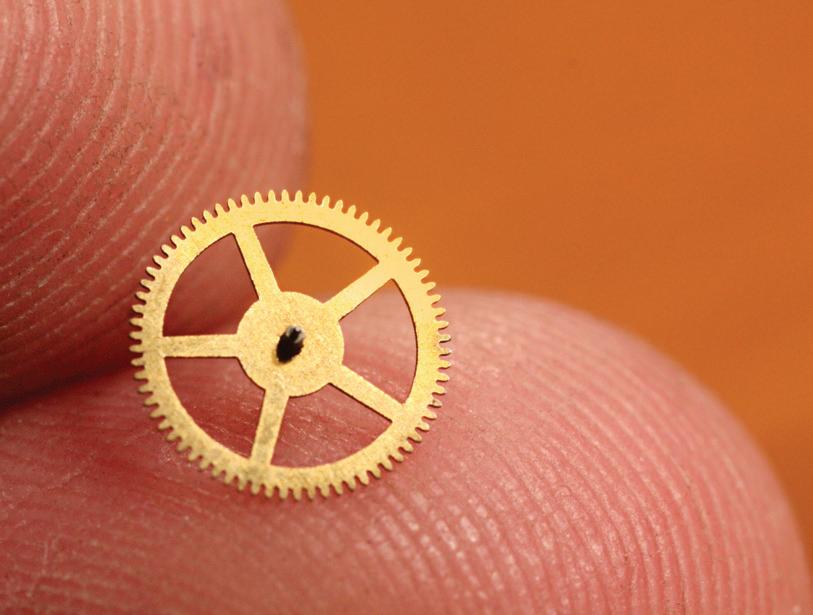
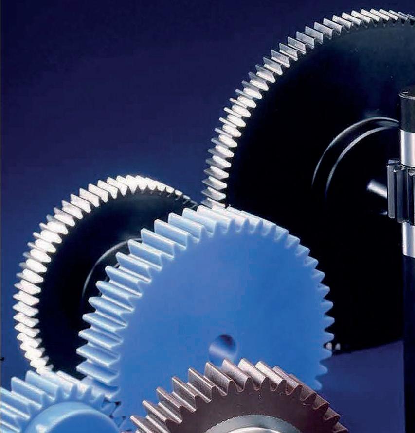
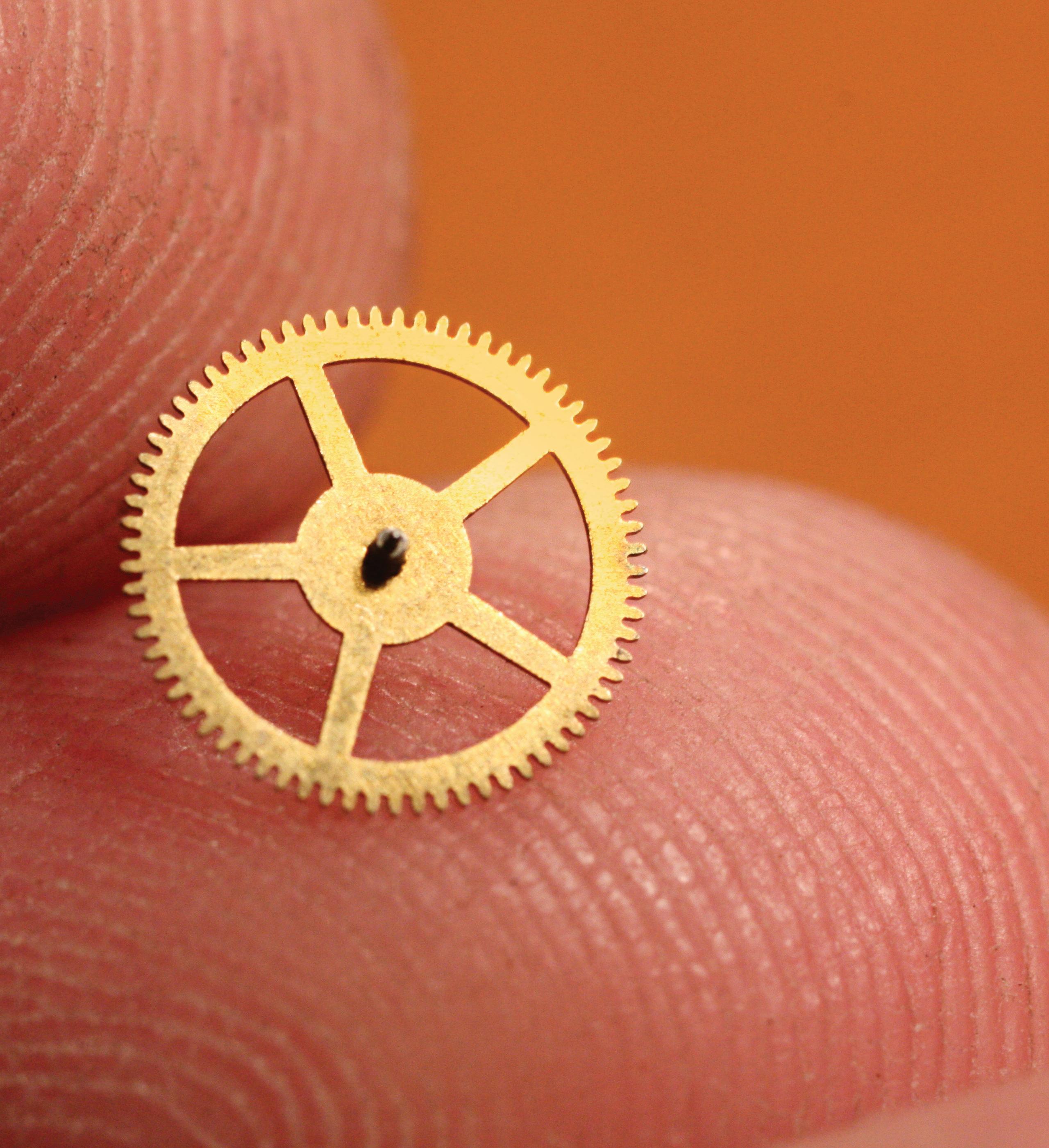
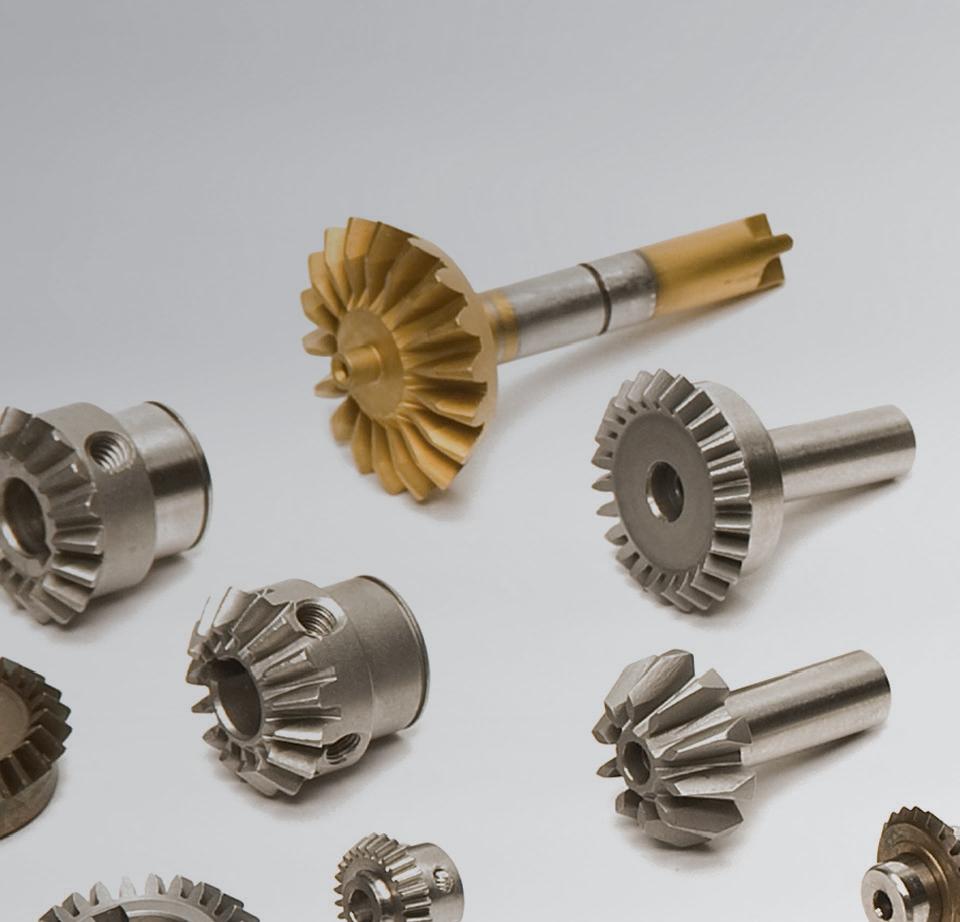
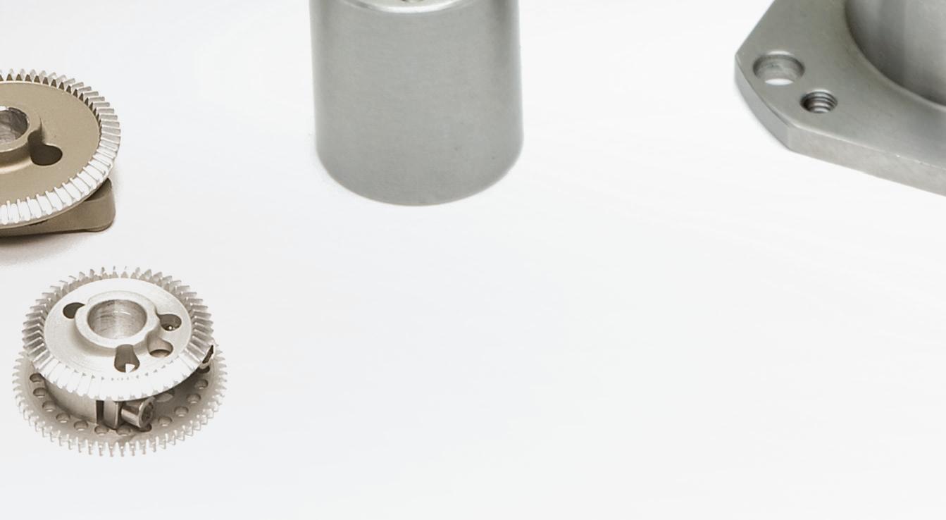
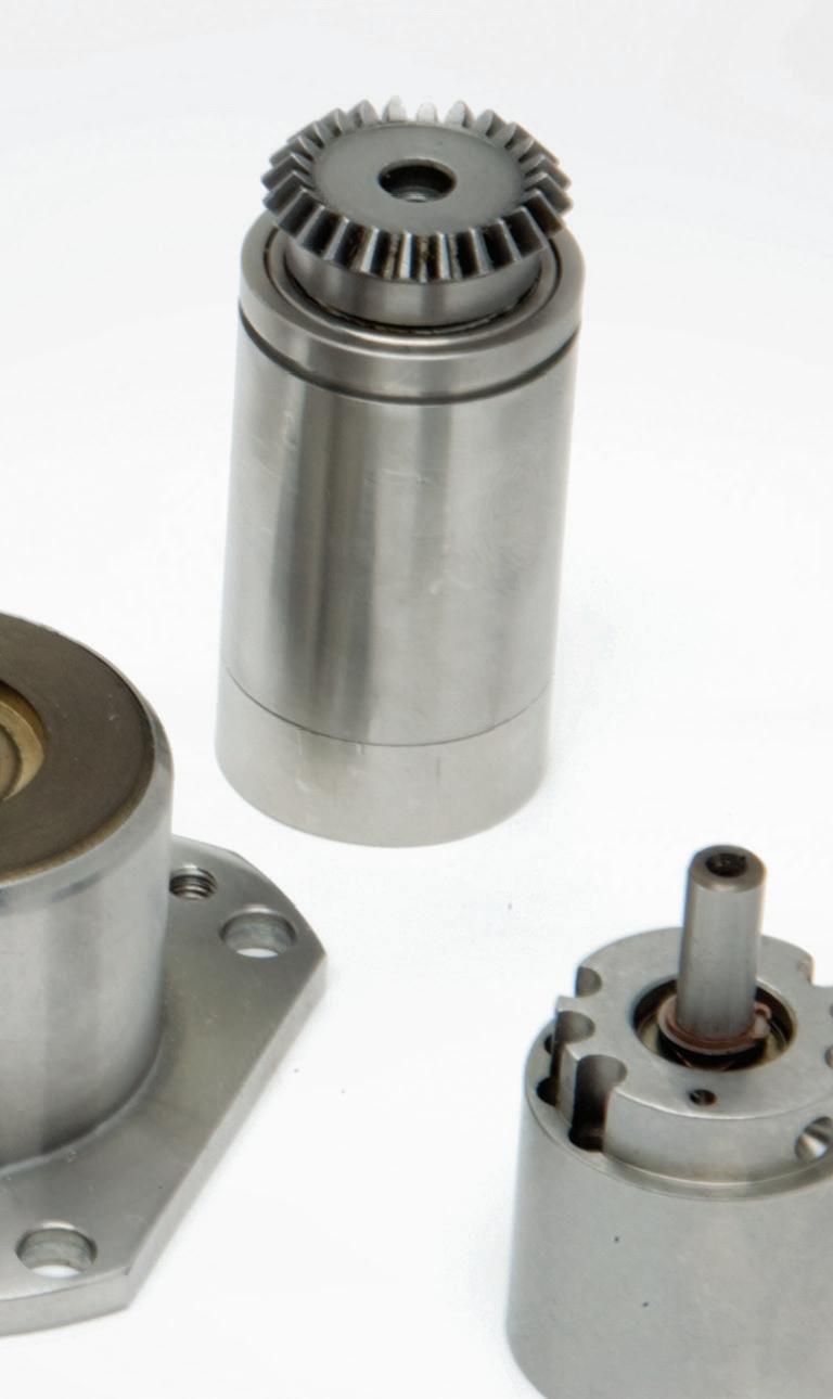
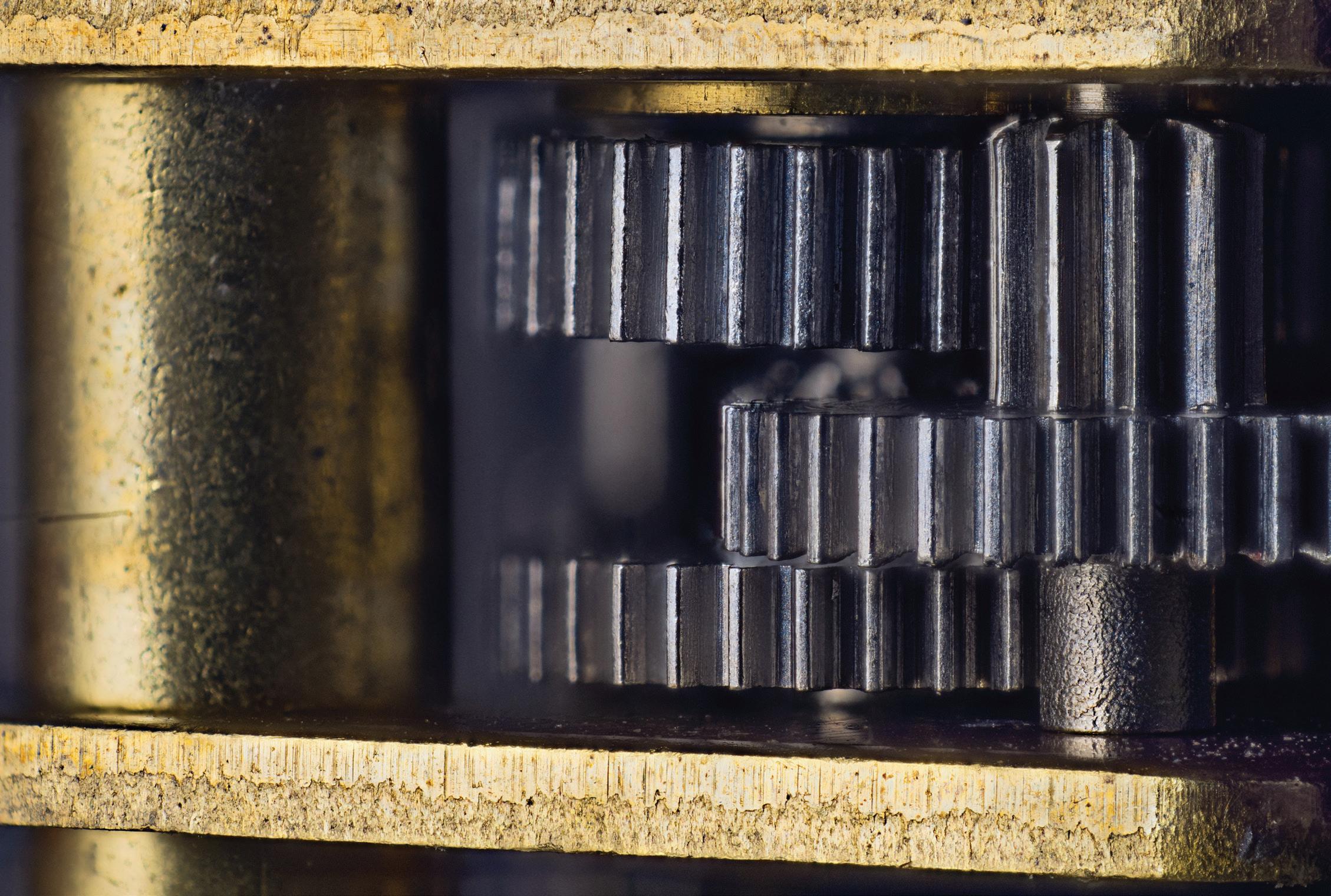
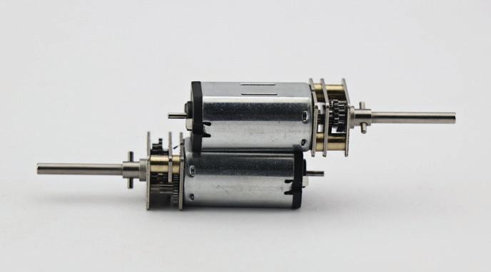
Miniature and microgearing with high precision and tight tolerances is used to deliver accurate low-backlash power transmission complementing small electric motors in:
• Medical devices and surgical tools
• Aerospace rovers and satellites
• Small motorized electronics.
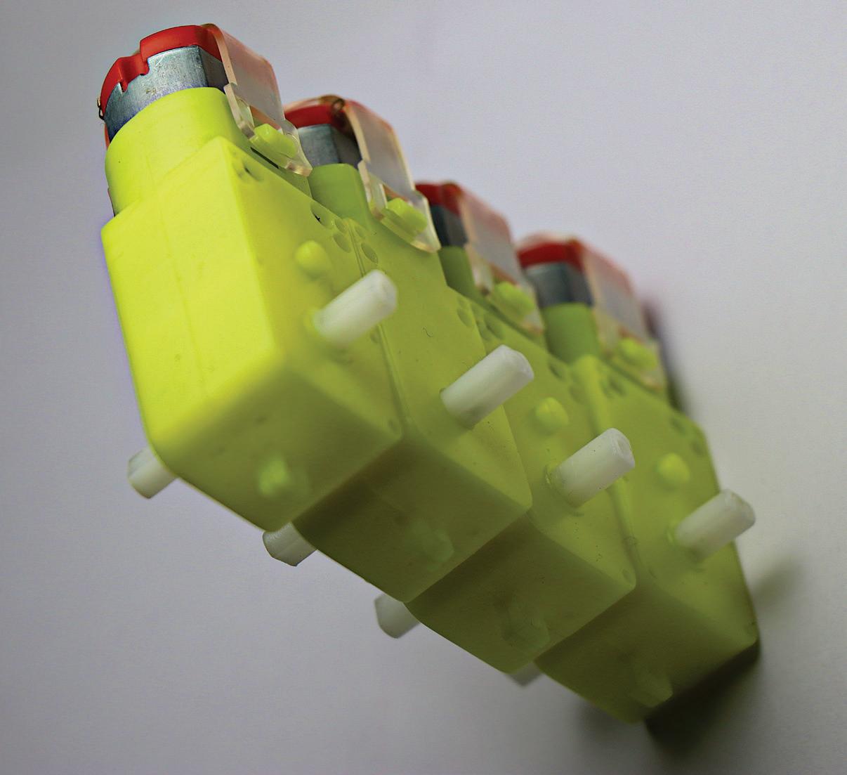
Hapticsgenerating motor-driven designs benefit from miniature gearing.
Such gearing is most often paired with small dc motors that are either brushed or brushless — with coreless permanent-magnet motor types increasingly common in these applications.
Consider a specific haptic application — that of electronic flyby-wire flight control. In these systems, a pilot’s steering movements aren’t transferred via conventional mechanical or hydraulic actuators. Instead, electronic transmission occurs via force-feedback feeling through the motor assembly in a joystick control column. Such haptics-generating motor-driven designs benefit from miniature gearing capable smooth backdrivability and simultaneously generating torque and force based on joystick position.
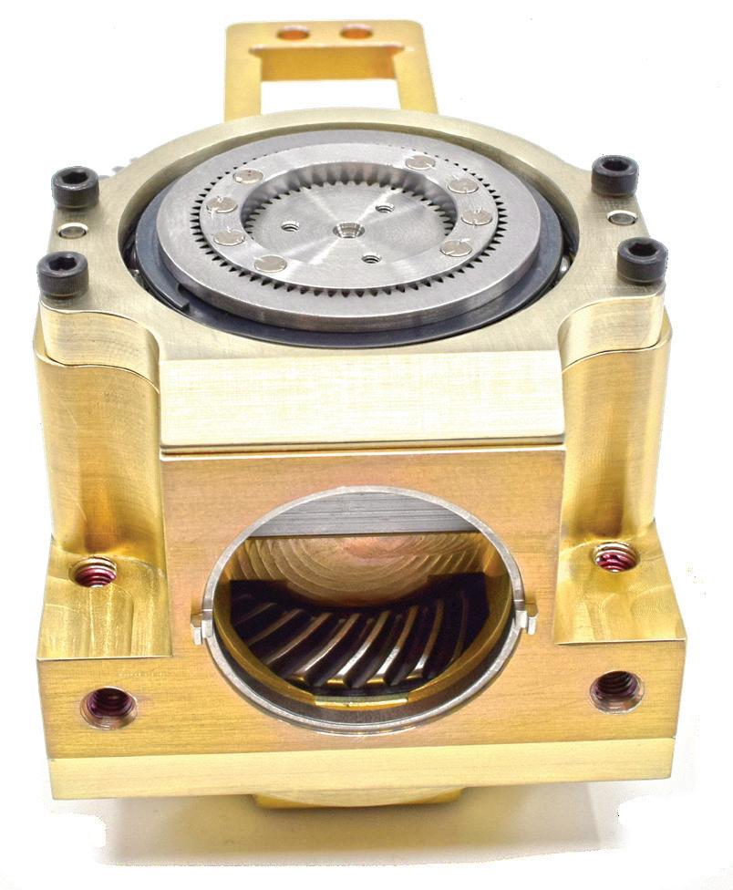
Gear arrangements in these and other miniature and microdesigns are often customized with specialty mounting geometries, tooth profiles, diameters, and integrated sensing or other components.
What’s more, such miniature gears are usually constructed from high-strength materials to maintain overall design compactness. Subcomponents of stainless steel, titanium, and specialized plastics and composites are common where the gearing is destined to be implanted in the human body due to these materials’ corrosion resistance and biocompatibility; for the latter, additional surface treatments are sometimes applied to gear housings to discourage bacterial growth. Gears made of noncorrosive materials are often

Miniature gears are usually constructed from high-strength materials to maintain overall design compactness.
Gear arrangements in miniature and microdesigns are often customized with specialty mounting geometries, tooth profiles, diameters, and integrated sensing or other components.
customized by component suppliers using precision molding and machining capabilities in controlled settings to satisfy FDA medical-manufacturing requirements.
Gear modules are a unit of measure defined by the International Organization for Standardization (ISO) expressing geartooth size or pitch, spacing, and how the gearset assembly meshes. Defined as the gear pitch diameter divided by the number of teeth, this module relates overall gear
size to that gear’s number of teeth. Sets of gears must have matching modules.
Miniature gearsets having 0.2 modules feature a 0.2-mm pitch diameter for each tooth. This makes for very fine and small teeth to operate in watches, micromotor-driven electronics, and small medical devices … though these gearsets can only be produced through advanced manufacturing approaches. Module-0.3, 0.4, and 0.5 gearing in contrast is common where more power is needed — as in small pumps and autonomous consumer electronics. Module-0.8 to 1.0 gearsets (at the high end of what’s generally considered miniature) deliver more torque than the smallest gears can provide for
small automotive, medical, and robotics applications.
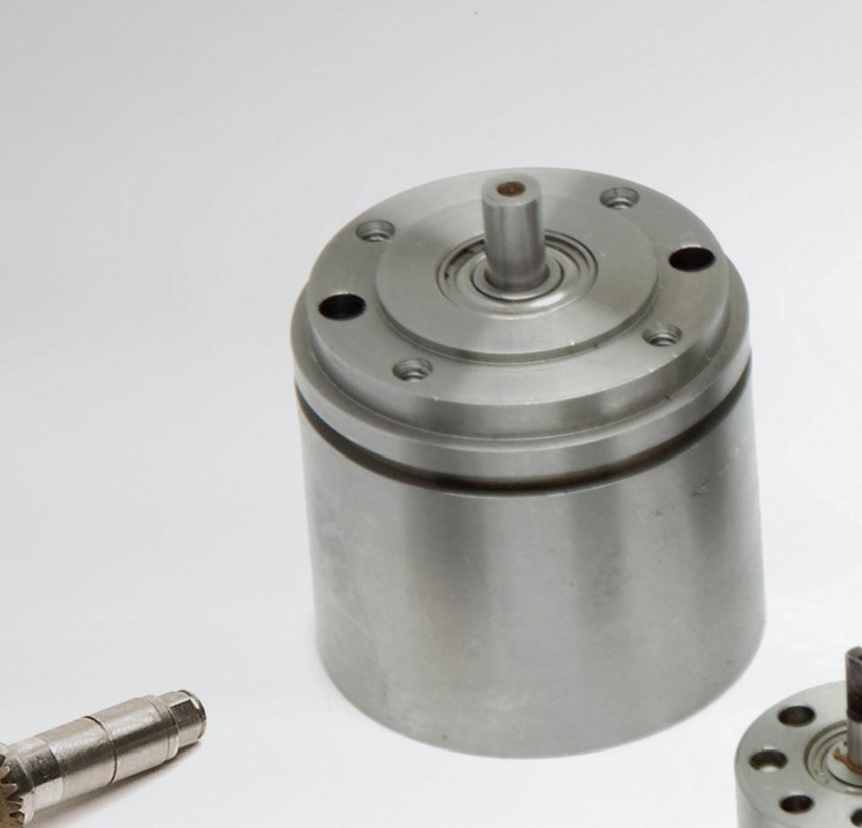
Miniature and microgears for medical devices must meet regulatory requirements and exacting standards to ensure patient safety. Satisfaction of additional sterilization, RoHS, biocompatibility, and MTBF requirements may also be necessary. Manufacture of these gearsets is often executed in cleanroom settings to ensure the substantial engineering, customization, and applied material science is expressed
Miniature and microgears for medical devices must meet regulatory requirements and exacting standards to ensure patient safety.


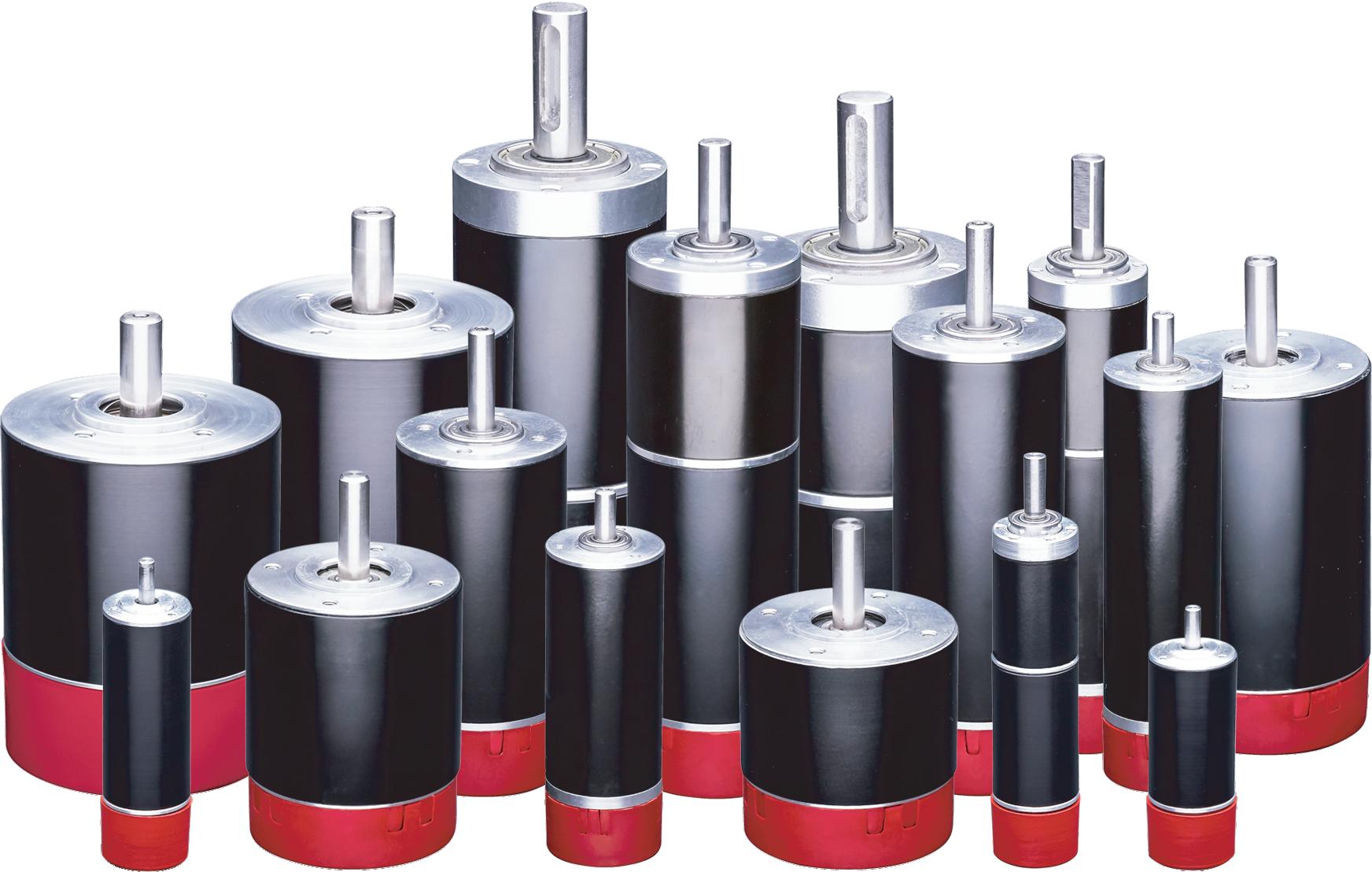
CGI Motion standard products are designed with customization in mind. Our team of experts will work with you on selecting the optimal base product and craft a unique solution to help di erentiate your product or application. So when you think customization, think standard CGI assemblies.

Connect with us today to explore what CGI Motion can do for you.


in the final component assembly. Machined and molded subcomponents are typically pre-integrated by the supplier for the same reason. That’s true whether a miniature gearset is produced for prototyping quantities or full production runs.
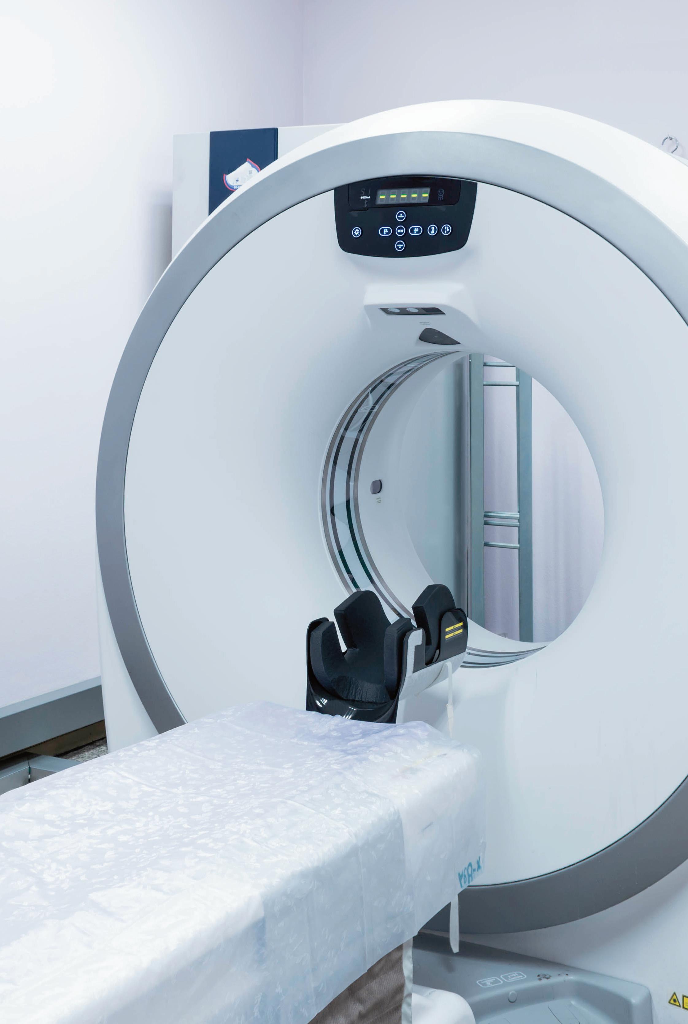
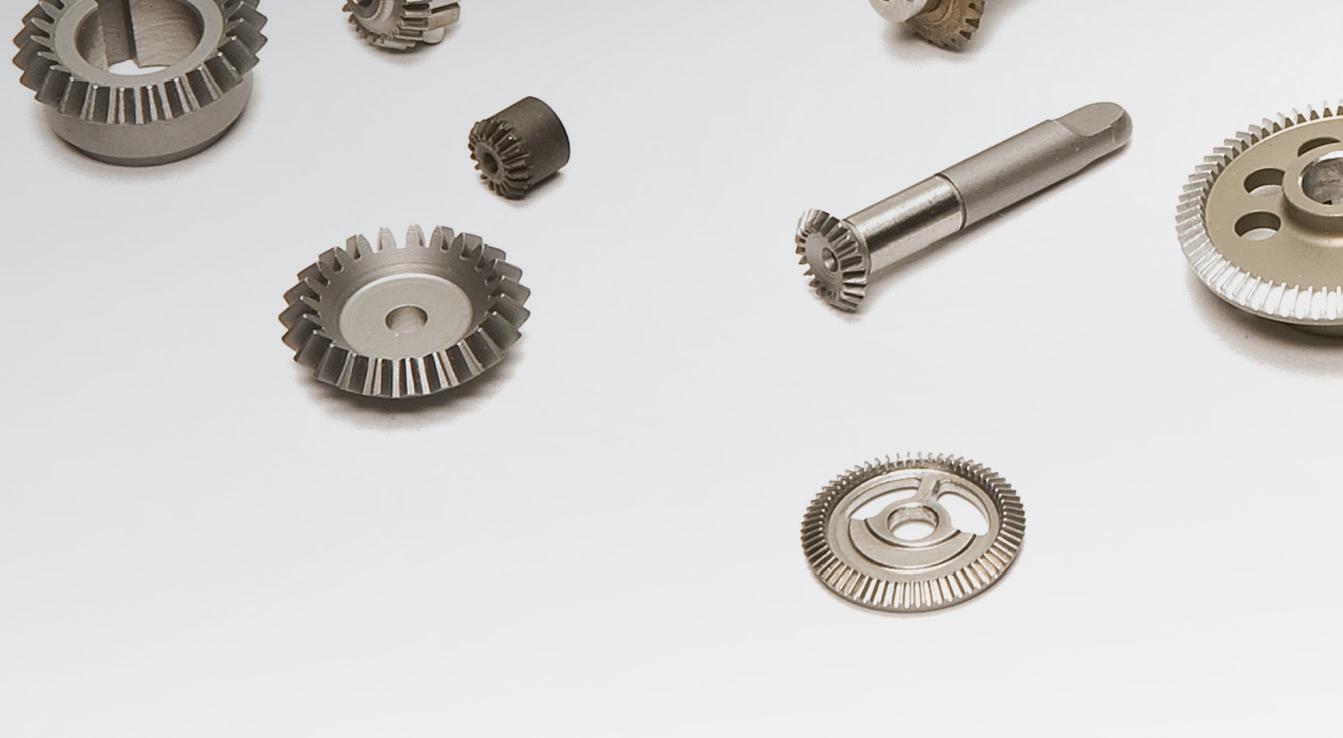
In laboratory automation, miniature and microgears in dc gearmotors are used in blood and gas analysis machinery, genomic testing equipment, cytometers, and automated diagnostic systems. The smallest gearsets find use in analyzers and centrifuges where exacting control over speeds ensures properly processed biological samples.
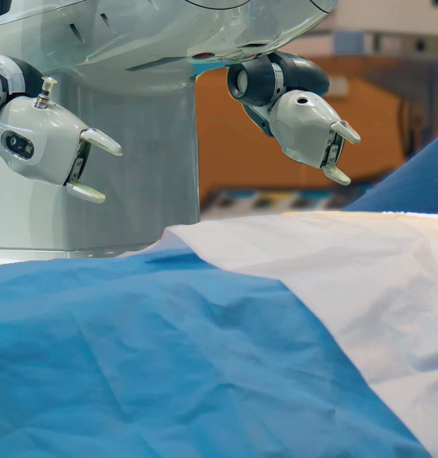
Miniature and microgears are used in medical robotics as well. Module 0.2 gears in particular find use in surgical robots to allow for accurate motion control over minimally invasive procedures. The compactness of such gearsets allows for the smallest possible robotic end effectors to delicately maneuver through and manipulate smallscale structures in the human body. Linear performance characteristics make motorized systems featuring these gears suitable for applications requiring tight motion control. Case in point: Ophthalmic surgical and diagnostics tools (for which accurate control is paramount) often
Our Certifications
ISO 9001 + AS9100
ITAR Compliant-DDTC Registered
DFARS Compliant
RoHS & R.E.A.C.H. Compliant
NIST SP 800-171 Compliant


Turning Ideas into Reality since 1950
Engineering development, design, and manufacturing expertise combined with mechanical and electromechanical component options.
We deliver parts and subassemblies complete, eliminating your need for additional sourcing, time, and cost.
Customized Solutions
Custom Gears & Mechanical Components
Custom Gearheads & Gearboxes
Complex Gear Assemblies
Mechanical Assembly
Electromechanical Assembly


incorporate module-0.3 gears to facilitate fine positioning of tools on delicate and complex eye structures.
Cardiorespiratory equipment as well as other medical fans and pumps also make copious use of miniature and microgears. Module-0.2 gears in micropump motorized designs (including those for renal care and drug-delivery systems) allow for precise control over fluids to ensure dosing is accurate. In contrast, the most common wearable insulin pumps (for which patient safety and treatment efficacy are paramount) feature precision module-0.3 gears. Other implantable medical devices such as cardiacassist devices, neurostimulators, and implants feature miniature and microgears primarily designed for long-term reliability.
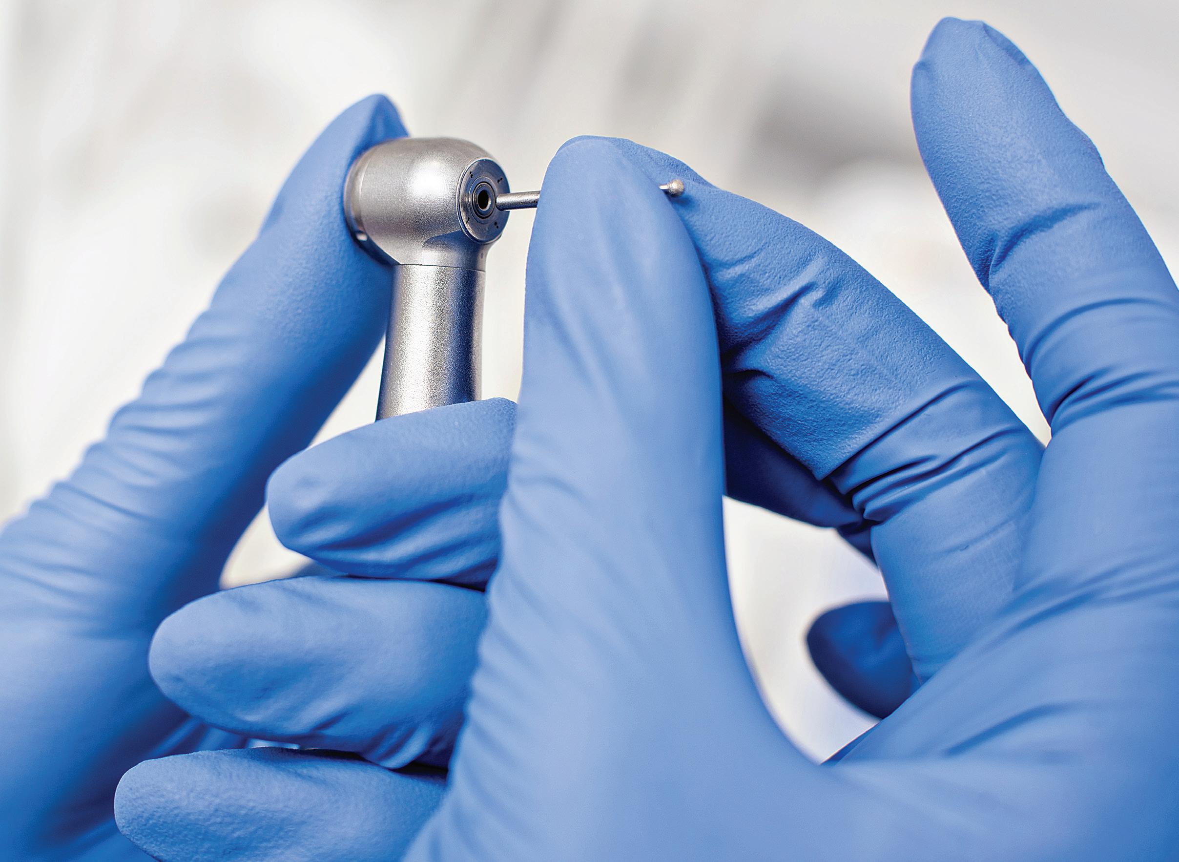
In handheld medical tools such as dental drills and portable handheld instruments for emergency medical services,


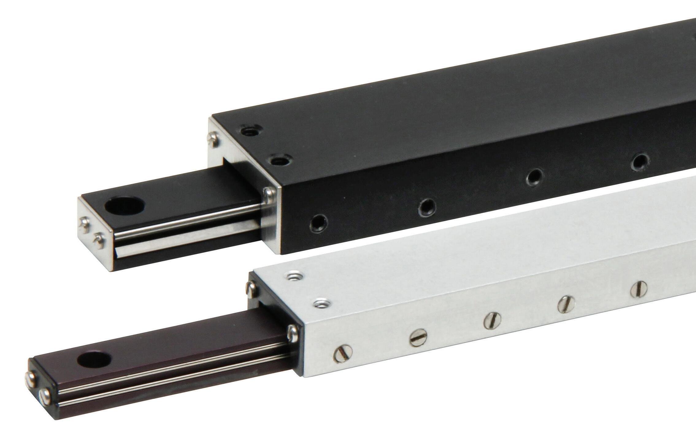

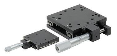
• Accuracy ranging from 0.0005”/” to 0.0000040”/” of travel.
• Low friction straight-line design reduces the coefficient of friction to 0.003.
• Factory preload adjustment prevents side-play and backlash.
• Lightweight aluminum carriage and base with high load capacity.
• Inch or Metric built-in holes simplify installation and component mounting.
• Available with ball slide or crossed roller slide technology, varying precision grades and corrosion resistant materials.
• Solid Models Available for all Del-Tron Models.
precision module-0.2 gears are widely used to maintain the design accuracy of lightweighted equipment. Many endoscopic and laparoscopic devices integrate miniature module-0.3 gears in tool end effectors that execute the precise cuts associated with biopsies and other manipulations.
Even the smallest gearsets require shaft bearings to allow gears to turn. Some include simple steel pins to serve as plain bearings. Others include modestly more rugged ceramic pins for plain bearings to satisfy high torque and life as well as low noise and backlash requirements. Still others incorporate FDA-compliant miniature ball bearings and pillow block bearings made of engineered plastic. However, the most demanding applications may benefit from needle roller bearings.
High-performance miniature products complete with miniature needle bearings on which the tiny gears spin allow backdriving and maximize efficiency, which is especially important on small battery-powered designs.
Consider haptics-reliant surgical robots for minimally invasive microsurgeries and telesurgeries. Doctors performing surgery via these robots dynamically and instantaneously feel forces equivalent to those exerted by the robot end effectors. Here, gearboxes with smooth backdrivability are essential. Miniature gearsets with needle roller bearings deliver on this parameter even on axes needing gear ratios necessitating two or three stages. Traditional gearing exhibiting uneven or sticky backdrivability is mechanically noisy and unusable in these robots.
Miniature gearing either employs oil or grease lubrication or features selflubricating elements compatible with the destination setting. Where oil or
In servo-driven applications where load inertia is high compared to motor inertia, miniature gearing can reduce settling time.
In the burgeoning field of motorized prosthetics and exoskeletons, module-0.3 gears integrate into motorized joints mimicking natural movements.
grease are used, cooler operation can significantly extend lubricant life (and gearset life with it) because there’s less thermal stress. So, gear teeth are slower to shed abrasive particles and the lubricant is slower to exhibit chemical breakdown. Of course, medical devices require the use of nontoxic and biocompatible lubricant.
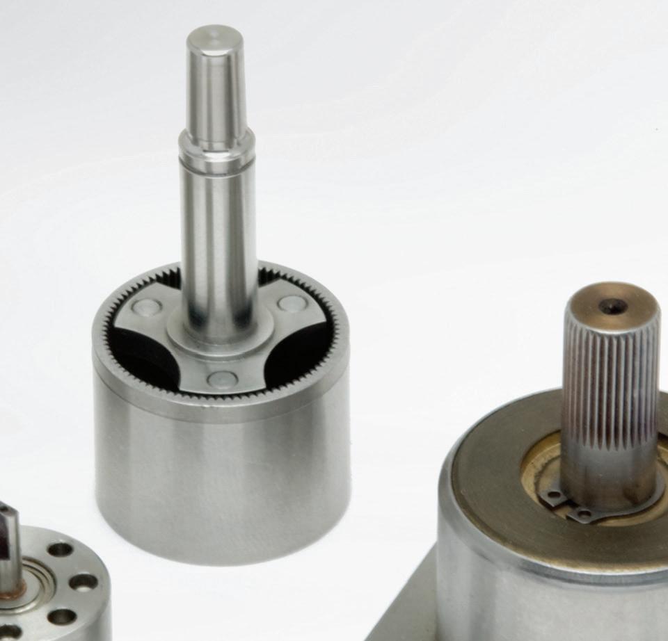
Miniature planetary gearsets offer advantages over other miniature gearsets including multiple kinematic combinations, power density, big reductions from compact setups, and pure torsional reactions. With precision sets, losses never exceed a few percent per stage. That’s helpful for boosting overall design efficiency and keeping assemblies cool — a key objective where miniature gear and motor pairings drive handheld tools.
Some miniature planetary gearing
with multiple stages can get efficiencies to 90% — far better than the 70% or so of comparable designs. So, if fitted with an otherwise identical motor and controller, a system with this gearing can output 30% more power or consume 20% less input to deliver a given output. If the design happens to use a brushed motor, that extends the brush and overall system life. Plus, more efficient gearing lets the motor operate higher on the efficiency-torque curve or (with the help of control electronics) allow use of a smaller and lighter motor.
Miniature planetary gearing efficiency is particularly useful in batterypowered medical devices and other miniature designs because it’s key to helping them operate longer between charges and battery swaps.
Miniature gearsets featuring rolling-element bearings mentioned earlier are especially well suited to haptic force-feedback applications because their smooth-turning planet gears allow repeatable backdriving from the system output. So, torque feedback via the gearset to the motor on the gearing’s input is consistently proportional to the load. Traditionally built planetary gearheads can’t guarantee smooth backdrivability or consistent load interpretation through the gearbox. That’s because of their fluctuating efficiency, variable tolerance stackup between gearbox internals, and the potential cocking of planet gears. •
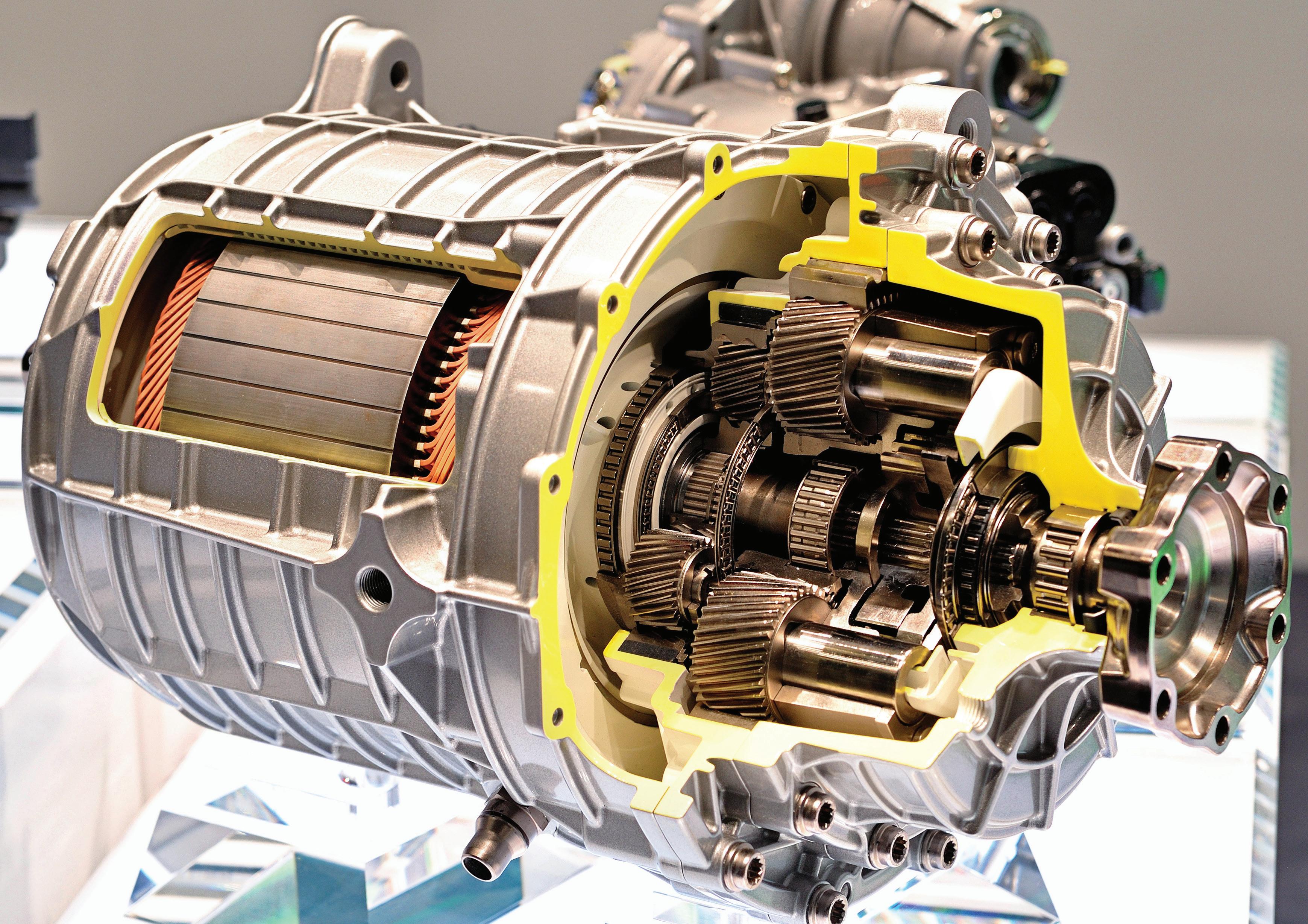
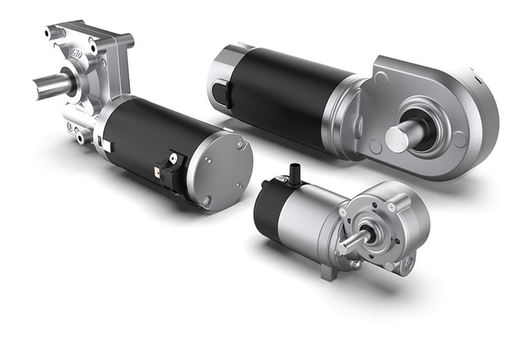
Gearmotors are electromechanical devices that integrate a gear reducer and either an ac or dc motor into one physical unit. More specifically, they transmit input torque from a motor to an output shaft through gearing, decreasing speed and increasing torque.
Gearmotors simplify design because they save engineers from integrating motors with gears, which in turn reduces engineering costs. If the application requirements are known, engineers can order the right gearmotor from a supplier directly.
A properly sized gearmotor with the right combination of motor and
gearing can prolong operating life and boost overall efficiency. Gearmotors also eliminate the need for couplings and potential alignment issues. Such problems are common when a design includes connecting a separate motor with a gear reducer.
A typical way to classify gearmotors is according to their horsepower rating;
as either fractional or integral. An integral horsepower gearmotor is any motor with a horsepower of 1 and above, as opposed to fractional horsepower motors that are less than 1 hp. The design considerations for integral horsepower motors are fairly similar to fractional horsepower motors because the same types of parameters are important. So, for instance, torque and

• Quick to configure • Quick to build • Quick to deliver
Over 75 years’ of expertise creating the perfect combination of motor and gearbox to match a wide range of applications. We offer thousands of standard options and can easily customize any motor or gearbox to meet your exact requirements. Our product range includes AC, PMDC, and BLDC options for applications in industrial automation, material handling, and mobility solutions
Parvalux can help your products really start to motor! Contact us today to ask about our Rapid Prototyping Services. Learn more: https://www.parvalux.com/us/modular-range
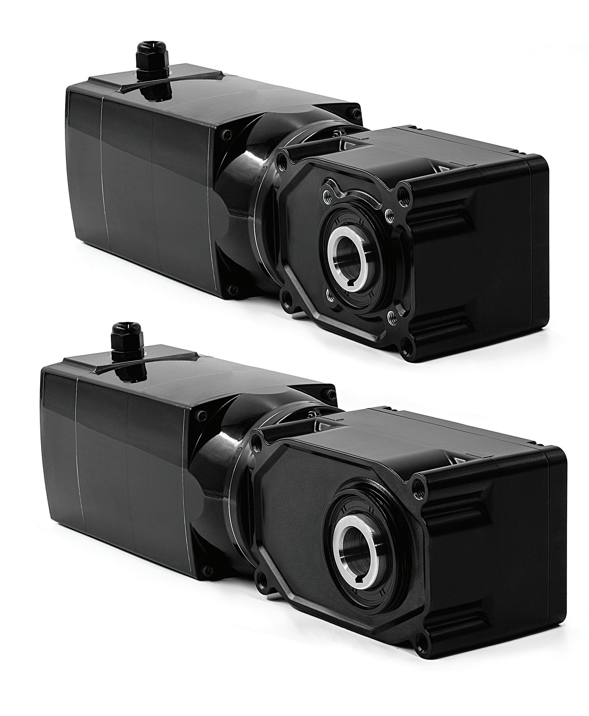
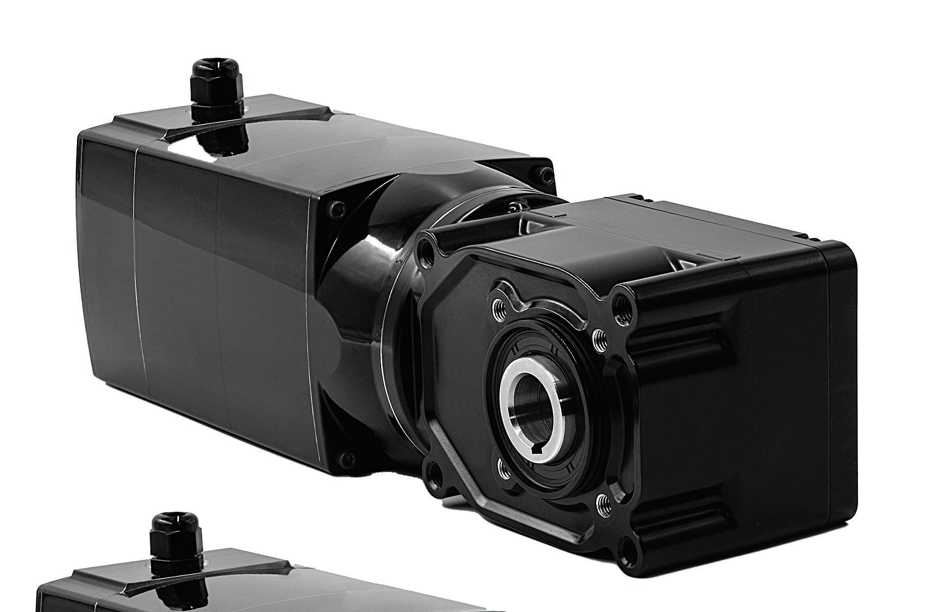
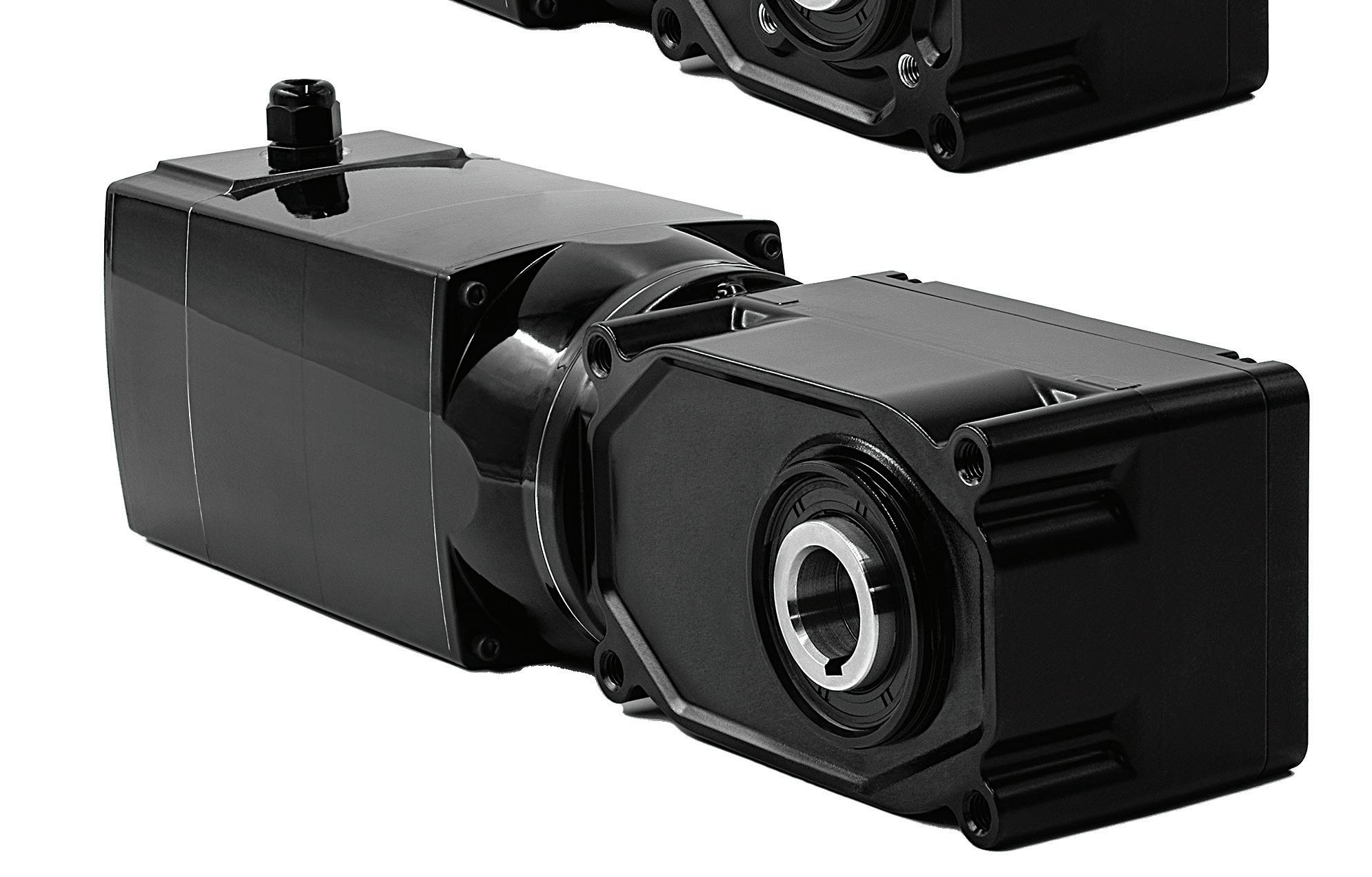
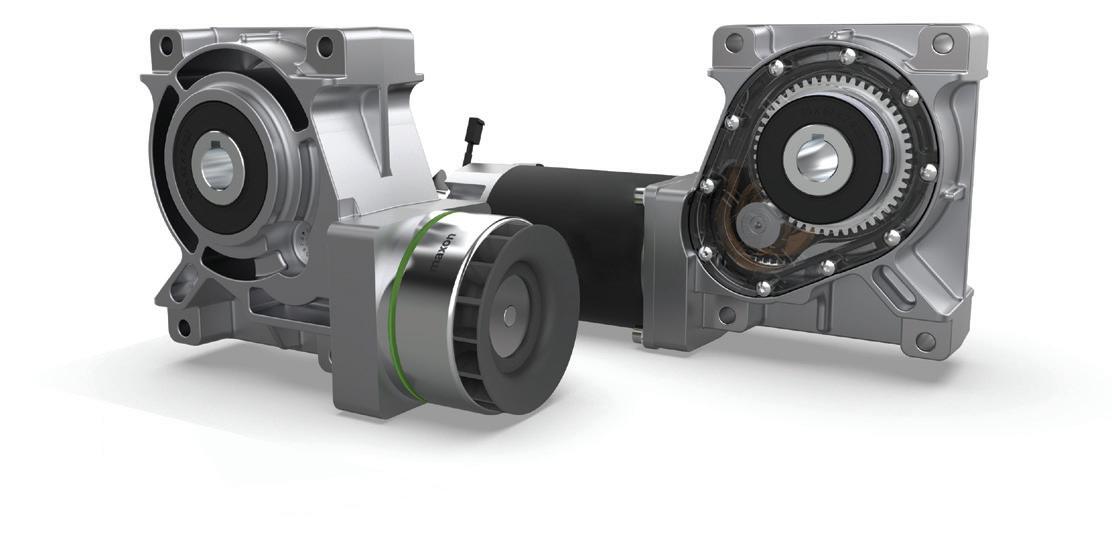
The model 42B-25H2 and 42B-30H3 hollow-shaft gearmotors from Bodine Electric combine a 130-V brushless dc motor with two hypoid gearheads, providing high-performance, maintenance-free alternatives to gearmotors with standard worm gearing. They’re available with gear ratios from 5:1 to 240:1, provide up to 2,370 lb-in (268 Nm) of continuous torque, and speeds of up to 400 rpm.
speed matter in all cases.
Another way gearmotors are differentiated or classified is by the output shaft orientation, with two standard types being parallel and right-angle arrangements. Beyond shaft configuration itself, other factors such as the type of gears used in the gearmotor determine performance.
Broader design trends impacting motion components as well as industries in general can be seen in gearmotor designs as well. For example, energy efficiency remains a key design trend, which is why gearmotor manufacturers
are designing with high-efficiency gearing, such as helical and planetary gears. Another shift is using brushless dc motors with integrated gear reducers for more energy-efficient operations.
Some gearmotor designs are also incorporating predictive maintenance features so as to monitor wear and detect performance issues before failure, helping to reduce downtime.
Another design trend is towards lighter and more compact designs. This is brought about by the expanding application uses for motors and other devices in, for instance, medical robotics and battery-operated power tools, among others. Here, miniaturization is critical for space savings. Together with the drive towards smaller components is the use of newer materials that support smaller gears. So, for instance, composite materials that are high strength as well as lightweight alloys of various types.
No matter the trends impacting gearmotor design, the basic calculations for selecting and sizing a gearmotor remain the same.
The first place to start when sizing a gearmotor is to determine the required output torque and speed. But once torque and speed are defined, you’ll also want to know the required input power for the motor — particularly if the gearmotor uses an ac induction motor, where the power rating (typically given in horsepower) is used as a key factor in sizing.
Before calculating the power, let’s review the relationship between power and work.
Work is force applied over a distance: W = F x D
W = work (J)
F = force (N)
d = distance, or displacement (m)
Get way ahead with adaptive automation
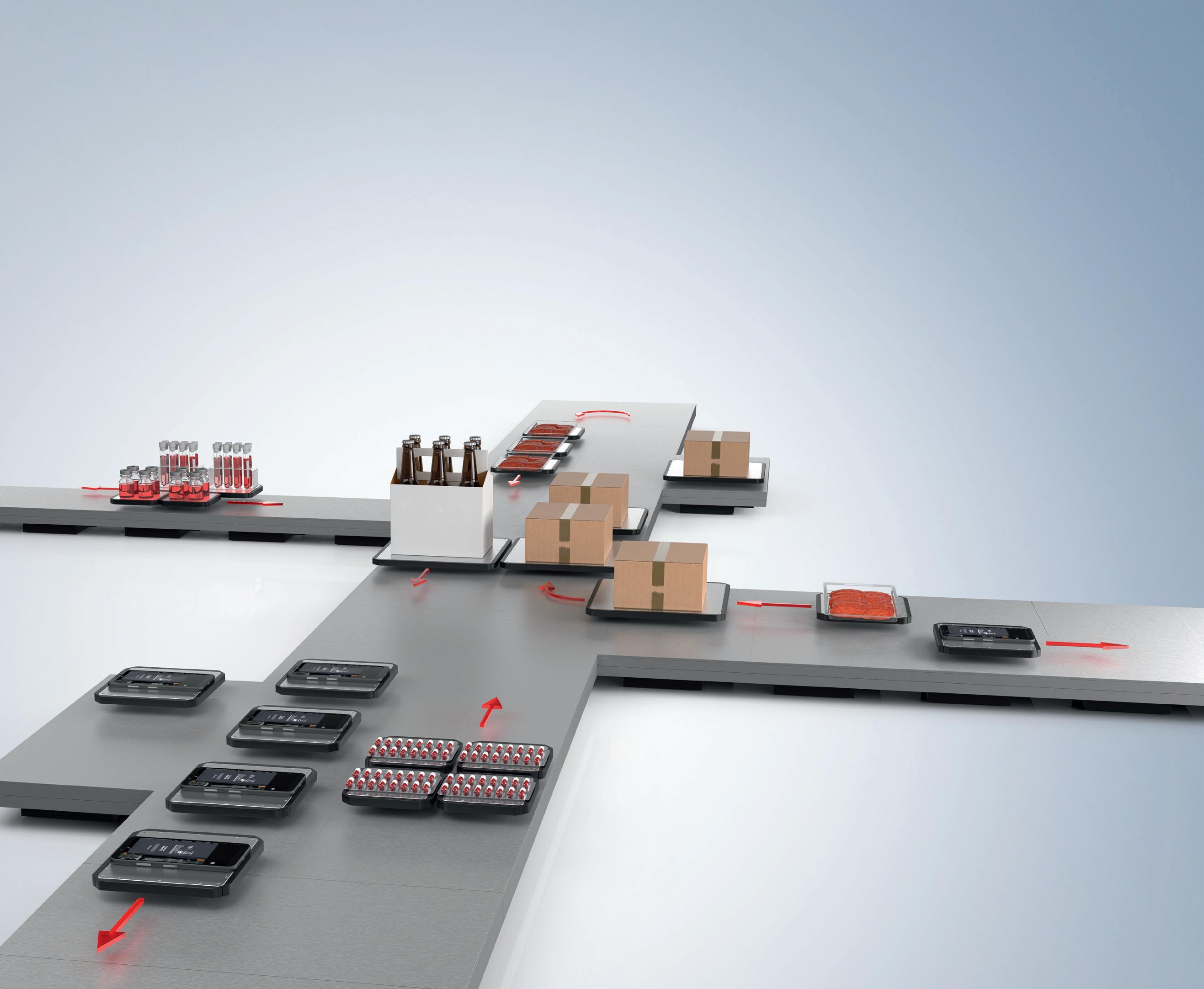

Elevate your automation game with XPlanar. Developed in-house by Beckhoff, this mechatronic system makes your material handling literally fly with magnetically levitating movers and base tiles that you can arrange to fit your unique applications – automated warehouses, distribution centers, microfulfillment, pharmaceutical fulfillment, material handling in manufacturing and beyond.
So, what will you do with XPlanar?
Movement and handling with up to 6 degrees of freedom
Transport and processing in one system
Wear-free, hygienic and easy to clean
Create nearly any layout and path you can imagine
Multi-mover control enables parallel and individual product handling
Fully integrated into the powerful and standardized Beckhoff control system (TwinCAT, IEC 61131, Motion, Measurement, Machine Learning, Vision, Communication, HMI)
Flexibly change paths in software and easily modify shape, size, and number of movers
Mechanical power is the time rate at which work is done, so work divided by time:
P = W / t
P = mechanical power (Watt)
W = work (J)
t = time (sec)
Mechanical power can also be written:
P = (F x D) / t
Note that distance divided by time (d/t) is velocity, so power can be written as force times velocity:
P = F x v
v = velocity (m/sec)
Electric motors produce torque (rather than force) through rotational motion (rather than linear distance), so power is equal to torque multiplied by angular velocity: P = T x ω
P = mechanical power (W)
T = torque (Nm)
ω = angular velocity (rad/sec)
Note that angular velocity has units of radians per second. If speed is given in rotations per minute (rot/min or rpm), be sure to convert rotations per minute to radians per second:
rad/sec = (rot/min) x (2 π/60)
Although the SI unit of power is the watt, in discussions of motor power, the Imperial unit of horsepower is often used.
In the 1780s, James Watt and Matthew Boulton defined 1 horsepower (hp) as 33,000 ft-lb/min, which, is 44,742 Nm/min.
Converting this from Nm/min to Nm/ sec gives us 746 Nm/sec, or 746 Watts. Therefore, to convert power from watts to horsepower, divide the power in watts by 746.
In gearmotor applications, torque and speed are still often given in Imperial units. In these cases, horsepower can be calculated directly, with the use of a conversion factor:
When torque is given in lb-ft and speed in rpm:
P = T x ω / 5,252
P = mechanical power (hp)
T = torque (lb-ft)
ω = angular velocity (rpm) 5,252 = 33,0000 ft-lb/min ÷ 2 π rad/rot
When torque is given in lb-in and speed in rpm:
P = T x ω / 63,025
P = mechanical power (hp)
T = torque (lb-in)
ω = angular velocity (rpm)
63,025 = 33,000 ft-lb/min * 12 in/ft ÷ 2π rad/rot


Each equation for mechanical power given above can apply when sizing a gearmotor, depending on what units of torque and speed are being used.
However, when determining the input power required for the motor, the efficiency of the gearmotor assembly at transmitting that power to the load must be taken into account. Therefore, regardless of which equation above is used to calculate the required output power, the required input power at the motor is calculated as:
Pinput = Poutput / η
η = gearmotor efficiency
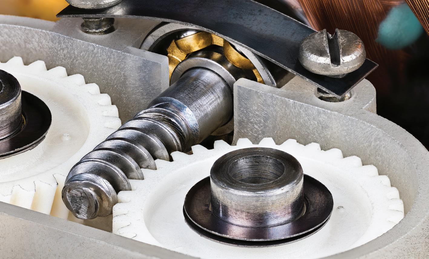
Note that efficiency can vary greatly, depending on the motor, type of gearing used, and the gear ratio. For example, gearmotors that use hypoid gearing can have efficiencies of greater than 90 percent, while those that use worm gears can have efficiencies ranging from less than 40 percent up to about 80 percent. •
EDITORIAL
VP, Editorial Director Paul J. Heney pheney@wtwhmedia.com
Chief Editor Rachael Pasini rpasini@wtwhmedia.com
Executive Editor Lisa Eitel leitel@wtwhmedia.com
Managing Editor Mike Santora msantora@wtwhmedia.com
Senior Editor Miles Budimir mbudimir@wtwhmedia.com
Ryan Ashdown rashdown@wtwhmedia.com 216.316.6691
Jami Brownlee jbrownlee@wtwhmedia.com 224.760.1055
Mary Ann Cooke mcooke@wtwhmedia.com 781.710.4659
Mike Francesconi mfrancesconi@wtwhmedia.com 630.488.9029
Jim Powers jpowers@wtwhmedia.com 312.925.7793
CREATIVE SERVICES & PRINT PRODUCTION
VP, Creative Director Matthew Claney mclaney@wtwhmedia.com
Senior Art Director Tory Bartelt tbartelt@wtwhmedia.com
Director, Audience Growth Rick Ellis rellis@wtwhmedia.com
PRODUCTION SERVICES
Customer Service Manager Stephanie Hulett shulett@wtwhmedia.com
Customer Service Representative Tracy Powers tpowers@wtwhmedia.com
Customer Service Representative JoAnn Martin jmartin@wtwhmedia.com
Customer Service Representative Renee Massey-Linston renee@wtwhmedia.com
Customer Service Representative Trinidy Longgood tlonggood@wtwhmedia.com
ONLINE DEVELOPMENT & PRODUCTION
Web Development Manager B. David Miyares dmiyares@wtwhmedia.com
Digital Production Manager Reggie Hall rhall@wtwhmedia.com
LEADERSHIP TEAM
Senior VP, Engineering Courtney Nagle cnagle@wtwhmedia.com 440.523.1685
CEO Matt Logan mlogan@wtwhmedia.com
CFO Ken Gradman kgradman@wtwhmedia.com 773.680.5955
FINANCE
Controller
Nirmit Shukla nshukla@wtwhmedia.com
Accounts Receivable Specialist Jamila Milton jmilton@wtwhmedia.com
MARKETING
VP, Operations Virginia Goulding vgoulding@wtwhmedia.com
Digital Marketing Manager
Taylor Meade tmeade@wtwhmedia.com
Digital Design Manager Samantha Goodrich sgoodrich@wtwhmedia.com
Webinar Manager Matt Boblett mboblett@wtwhmedia.com
DESIGN


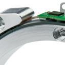
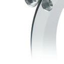
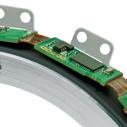
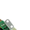
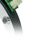
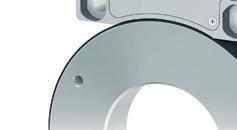
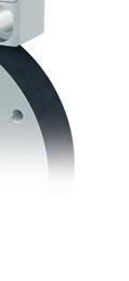
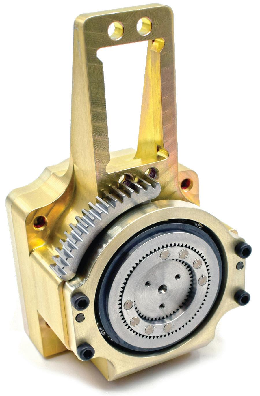
MULTITURN ENCODER
EMPLOYING LAYERED IC WITH FERROMAGNETIC TRACKS
Some sensors employ a cross shape directly affixed to a silicon chip to allow production of sinusoidal and cosinusoidal output in response to magnetic fields at right angles in a 2D plane.
THE APPLIED FIELD ALIGNS THE MAGNETIC MOMENTS.
So, what if an application needs a sensor to track an axis 360 ° and beyond? Absolute encoders need a power source and (for some designs) can be prohibitively costly while potentiometers can lack sufficient resolution. So, for applications not satisfied by these other options, multiturn shaftless rotary sensors are a leading option. These multiturn sensors:
• Track linear or rotary actuators’ drive-spindle positions over many turns.
• Supply control systems with data to actuate low-cost fluid-power and electromechanical drives sans gearing.
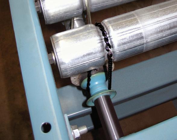
• Monitor powered conveyor rollers and drums in spool-related applications.
• Monitor angles prompted by steering-wheel rotations in automotive applications.
• Detect how open roll-up doors are in warehouse settings.
Many sensors billed as multiturn variations leverage the giant magnetoresistance or GMR effect. GMR is a quantum mechanical phenomenon in which a layered structure’s electrical resistance changes with the layers’ relative magnetizations. With parallel magnetizations, electron scattering and resistance are low. With antiparallel magnetizations, they are high. Some multiturn sensors also feature a domain wall generator or DWG with boundaries between magnetic regions to work like tiny switchable zones. These boundaries change how easily electricity flows so the sensor can record movement counts via magnetic changes — and in some cases, store that data for years.
Within the sensor electronics, a reference layer with fixed magnetization sits atop other sensor and memory layers (complete with an inward-spiraling track) that limit magnetization to 0° or 180° with shape anisotropy. The large size of the DWG pool of magnetic domains prevents shape anisotropy and allows its magnetization direction to align with field of the
ELECTRONS OF ONE SPIN TYPE FLOW THROUGH.
Atoms have magnetic moments arising from the very fields they produce. Magnetization changes with that of a given electron’s motion when subject to an external field. In layered composites, random magnetization impedes all electrons. But aligning moments and applying a magnetic field lets through a deluge of electrons of one spin so resistance plummets. Called giant magnetoresistance or GMR, enhanced adaptations of this effect are employed by certain multiturn sensors.
sensor’s target magnet.
When the magnet rotates with the machine axis to which it’s attached, it causes the DWG to release magnetic-domain groups (aligned to either 0° or 180°) into the track … and then the cycle repeats at 360° to affect subsequent sensor track segments.
The segments’ resistances are measured and processed by an integrated circuit; the number of segments possessed by the inward-spiraling track determines how many axis rotations the sensor can count.
In fact, some variations of these multiturn shaftless sensors can track 16 turns and beyond with 16-bit resolution and ±0.25% linearity. •
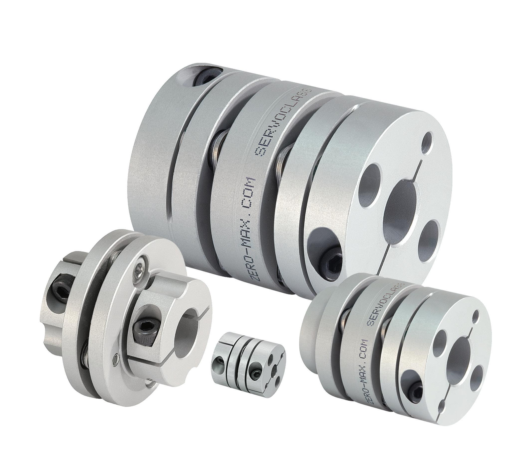
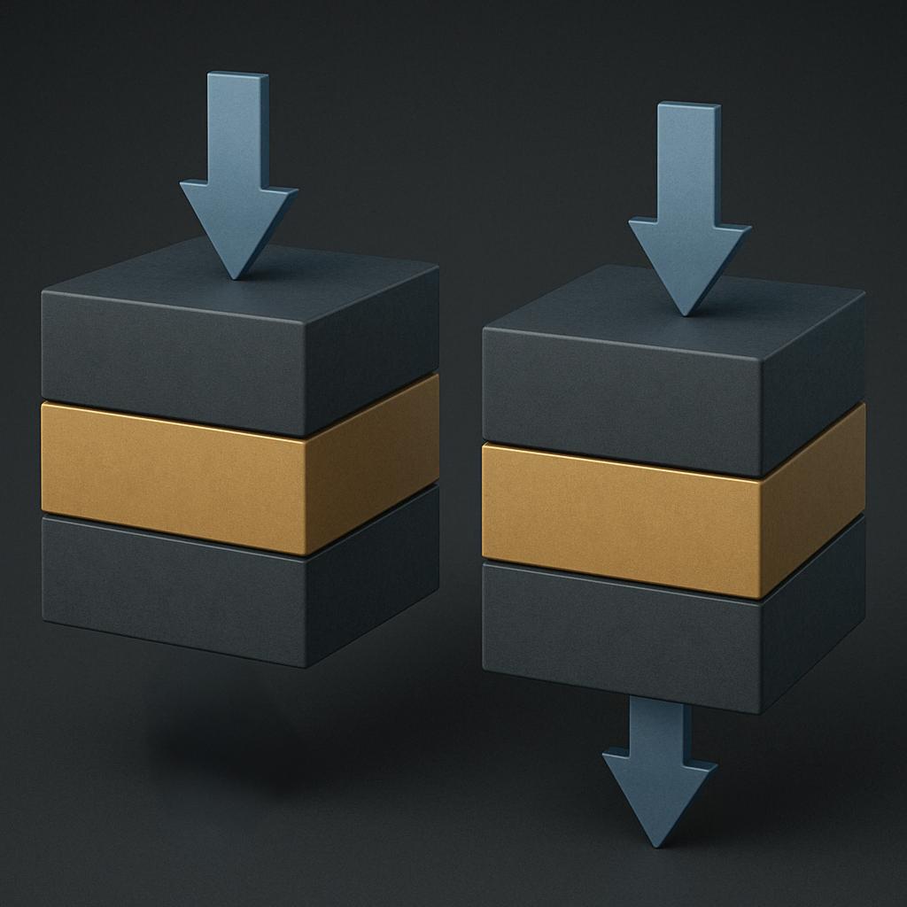
• Bore sizes up to 1-3/4” and 45mm
• Torque up to 1150 in-lbs (130 Nm)
• Reduced vibration due to a balanced design
• Double disc for increased misalignment
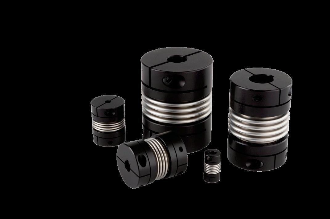
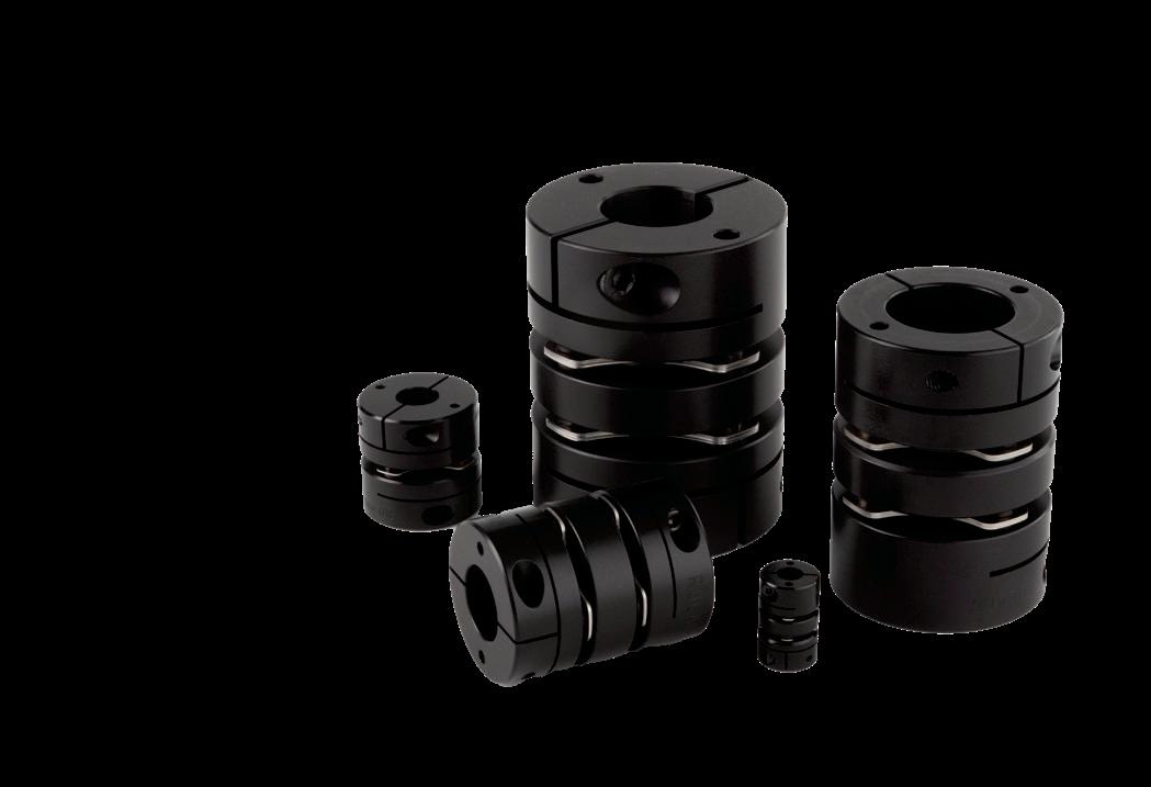
• Bore sizes up to 1-3/4” and 45mm
• Torque up to 1300 in-lbs (152 Nm)
• Reduced vibration due to a balanced design
• Highest torsional stiffness
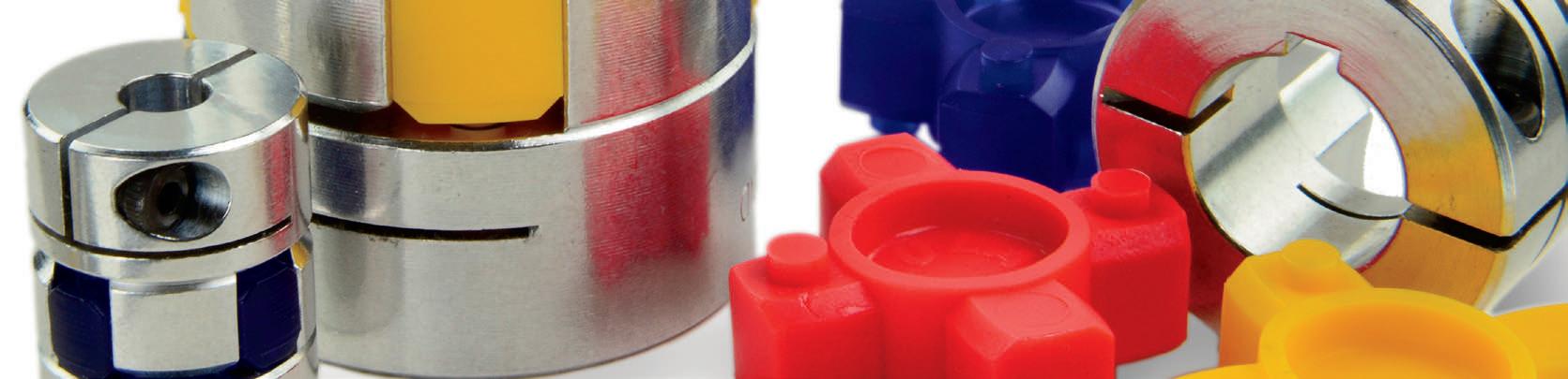
• Maximum mounting flexibility with drilled holes
• Most secure mounting connection with thread- ed holes
• Bore sizes from 3/8”-2” and 10-50mm
• Carefully made by Ruland in aluminum, steel, and stainless steel
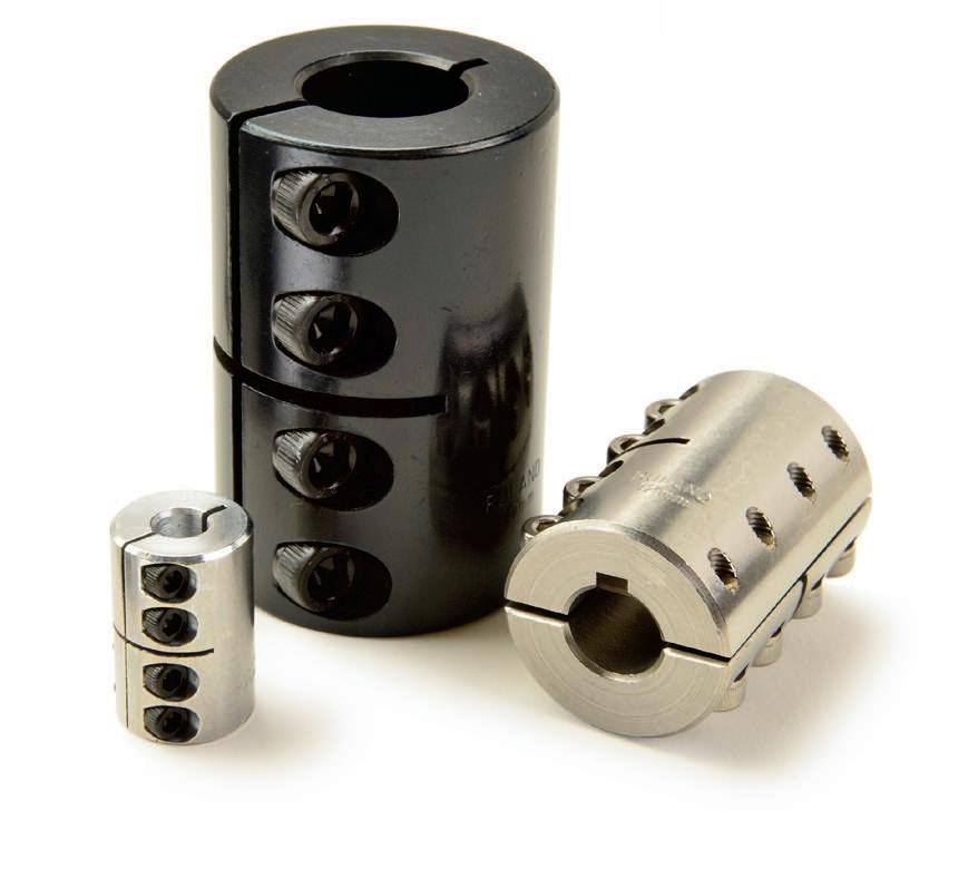
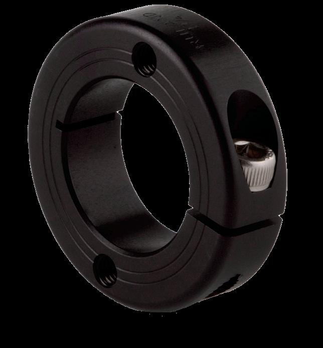
• Widest selection of standard inch-tometric bores with or without keyways
• Supplied with proprietary Nypatch® anti-vibration hardware
• One-piece style for easy installation
• Two-piece style with a balanced design


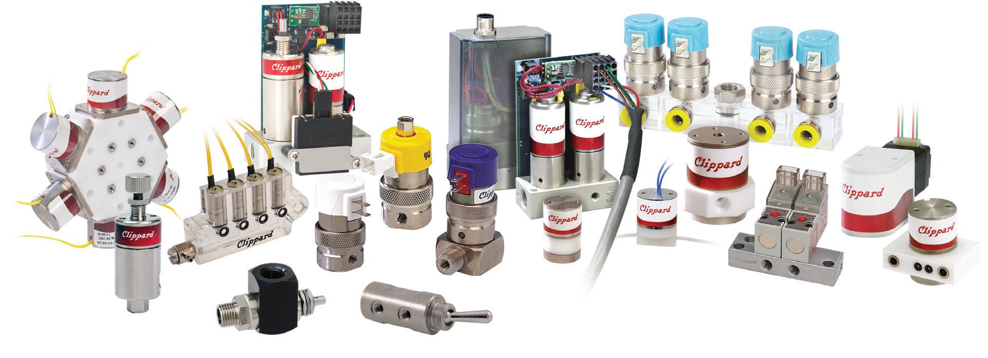
Designing efficient systems involves much more than simply understanding a few basic principles. There is a true art to balancing the specific requirements of an application in order to achieve the desired goals in the best possible way. Help us understand the unique needs of your application and together, we’ll develop something that surpasses what any of us could have done alone.
Contact your distributor to learn more, or visit clippard.com to request a free catalog and capabilities brochure.