
K100 & K300 Wood Pellet Stoves

INSTALLATION AND OPERATING INSTRUCTIONS
This appliance is hot while in operation and retains its heat for a long period of time after use. Children, aged or infirm persons should be supervised at all times and should not be allowed to touch the hot working surfaces while in use or until the appliance has thoroughly cooled.
When using the stove in situations where children, aged and/or infirm persons are present a fireguard must be used to prevent accidental contact with the stove. The fireguard should be manufactured in accordance with BS 8423:2002.
Setting the Language for the first time.
To set the Language to English on the controller.
Press the menu button until set is displayed beside the menu button.
Press the + button 4 times , display shows configura.......
Press the set button twice until abbreviation for languages in the top and centre of the screen.
Press the + button until abrreviation EN is displayed.
Press the Menu button to set the language to English.
STANLEY PELLET STOVE WARRANTY
CONDITIONS OF WARRANTY
Your Stanley pellet stove is guaranteed against any part that fails (under normal operating conditions) as detailed in the following table with timelines specified from the date of installation of the appliance. If the unit is not installed within six months of date of purchase, the warranty will commence six months from the date of purchase.
Warranty Period
Up to 1 Year
Up to 2 Years
Parts Covered (Parts & Labour unless Stated)
Refractory materials (supply only)
Rope seals, glass seals and cement seals.
Surface Finish on Seno models.
Grates and fire bars.
Ceramic glass is covered for Thermal breakage (supply only).
Rust (if reported before installation)
Aesthetic Damage (provided reported on date of receipt)
Electrical components under normal operation.
All external casings & enamel finishes (excluding impact damage or damage caused by overfiring). Pictures of damage must be submitted to WS Service Department.
All warranty claims must be reported to the Waterford Stanley Service Department and must be submitted with the product serial number (located on the data plaque at the rear of the product), date of purchase, proof of purchase (if requested) and details of the specific nature of the problem.
The warranty is given only to the original consumer/purchaser only and is non- transferable. The appliance must be installed by a suitable qualified person and installed as per the requirements of the manual. Failure to comply with the Installation requirements or Building Regulations will void your warranty. Waterford Stanley reserve the right to replace any part due to manufacturing defect that fails within the warranty period under the terms of the warranty. The unit must be used for normal domestic purposes only and in accordance with manufacturer's operation instructions.
LIMITS OF LIABILITY
The warranty does not cover:
* Special, incidental or consequential damages, injury to persons or Property, or any other consequential loss.
* Any issue caused by negligence, misuse, abuse or circumstances beyond Waterford Stanley s control.
* Any issue with wear and tear, modification, alteration, or servicing by anyone other than an authorized service engineer.
* Installation and operational related problems such as draught related issues external to the stove, inadequate venting or ventilation, excessive flue offsets, negative air pressure caused by insufficient burning of improper fuel.
* Damage caused to the unit while in transit.
* Discolouration due to over firing, damage caused by impact, damage to baffles caused by over firing and fading of surface finish on casting.
* Stress fractures on bricks.
* Rust on cast iron parts unless reported prior to unit being installed.
* Aesthetic damage, rust & missing parts on units purchased off display.
* Electrical components where voltage variations are in excess of 10% of nominal 230V
Note: Adequate clearance must be maintained around the appliance to ensure the ease of part removal in the possible event of their damage/failure. Waterford Stanley are not responsible for any costs incurred in the removal of items installed in the vicinity of the appliance that have to be moved to facilitate a part replacement.
IMPORTANT OPERATION / MAINTENANCE NOTES
N.B.: The information in this manual is given as guidance, all local, national or EC regulations must also be complied with.
Before using this appliance, please read all parts of this instruction manual carefully, as the information it contains, is essential in order to use the appliance correctly,
Make sure you fully read and understand the instructions contained in this manual before using the Pellet Stove as a biomass heating unit.
Do not touch the stove especially the control panel with wet or damp hands.
Do not burn fuel with a high moisture content, ie damp pellets.
Do not tamper with the safety devices or adjustment features without prior authorization from Waterford Stanley
During the first firings it is recommended to ventilate the room as an unpleasant (not toxic) odour may be emitted as the paint is completing curement.
Empty the ash container and clean the combustion chamber after burning of every 30kg of pellets.
Check flueways before lighting especially after a shut down period.
Allow adequate air ventilation to ensure plenty of air for combustion at all times.
Never turn off an operating pellet stove unit by disconnecting the electric plug. Disconnecting the plug will prevent the extraction of combustion fumes;
The only fuel that should be used for operation of the pellet stove are pellets certified by EN 14961-2 grade A1 with a diameter of 6 mm and a length that can range from 10 to 30 mm.
Keep all combustible materials a safe distance away from unit, please see section for clearances to combustibles.
Never use aerosol spray near the appliance when it is in operation.
For safety reasons never leave children or the elderly unaccompanied while stove is in use. Use a fire guard.
This appliance should be regularly maintained by a competent service engineer.
Please keep the packing materials away from children; The manufacturer will not be responsible for any modifications made to this appliance by or on behalf of the user. The manufacturer will not be responsible for any eventual damage or loss as a result of unauthorised modifications. In the event that parts need to be replaced, only use parts recommended by Waterford Stanley.
Flue System
1. Minimum Flue Height of 2 metres.
2. Tee piece fitted at base of flue.
3. Appliance should be connected using an 80mm connecting flue pipe, increasing to 125mm within 1.5 metres of the appliance
4. Horizontal run of connecting pipe must not exceed 600mm.
5. All flue pipework passing through walls must be sleeved & adequately insulated in line with current Building Regulations.
6. An appliance connected to a chimney must be lined with an 125mm flue liner.
7. The chimney/ flue termination must be located in accordance with building regulations part J.
8. The chimney serving this appliance should not serve any other appliance.
9. Access should be provided to the chimney serving the appliance to allow for cleaning.
10. It is a requirement by Building Regulations to have a carbon monoxide alarm fitted to any room with a solid fuel appliance.
11. A suitable cowl must be fitted at the flue termination to prevent excessive wind effects and rain entering the flue.
Location
11. Clearance to combustible materials must be adhered to as described in the Clearance to Combustible section.
12. The stove must be installed on a floor protector that covers the area under the stove and extends 9 to the front and 6 to the sides.
13. Clearance must be maintained to allow for maintenance and part replacement.
Ventilation & Combustion Air Requirements
14. The room in which the appliance is located should have an air vent of adequate size to support correct combustion (see Ventilation & Combustion Air Requirement Section for specific details).
15. The stove must not be installed in the same room as an extractor fan.
Technical Specifications


K100
Contents
The package of this unit contains:
Free Standing Pellet Stove K100, or K300
Instruction manual
Power cable;
Infrared remote control; Cleaning bar handle; Covers according to selected model.
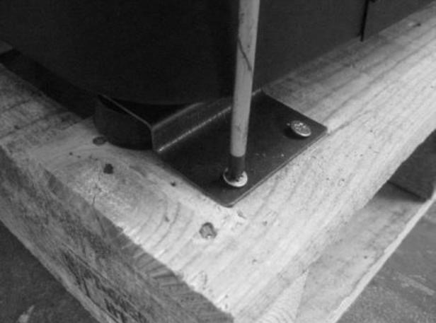
Unpacking the Unit
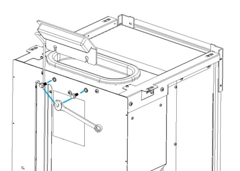
To unpack the equipment, you must first remove the retractable bag that surrounds the cardboard box. Then remove the box, lifting it up, and remove the bag that surrounds the stove and the packaging. To complete the procedure, unscrew the four brackets that secure the unit to the wood pallet (Figure 1).

Installation Requirements Installing the Pellet Stove 1 Location, Suitable area to be heated. Floor support / Hearth.
Remove the instruction manual from the package, it must be passed to the homeowner following installation.
Before installing the unit, please follow these steps:
Check immediately after receipt if the delivered product is complete and in good state. Any defects should be noted before installing the appliance.
The unit is equipped with four feet at the base, adjustable in height, allowing for the easy regulation when installing the unit on a non-levelled surface.
Flue connection capable of producing 12pa flue draught.
Adequate air supply for combustion/ ventilation
Location
The floor should be capable of supporting the weight of the product and hearth. A solid non combustible hearth of minimum thickness 12 mm, The hearth should extend 150 to the side and 225mm to the front

Fig. 2
The appliance should be installed centrally in the area to be heated.
Fig. 1
Flue/ chimney installation Electrical connection
The appliance must be connected using a connecting pipe of diameter 80mm. . A Tee piece must be installed at the base of the chimney to allow for cleaning/ inspection. The main section of the flue should be installed using a diameter 125mm flue pipe which must begin within 1.5 metres of the appliance flue outlet
Single wall flue is permitted in the area to be heated, outside of that area the flue must be insulated.
If the flue is to be routed though an existing chimney it can be done using a flexible stainless steel pipe with a register plate at the base of the chimney , the area in the chimney external to the flue liner must be back filled with insulation.
Where the flue pipe is installed external to the dwelling, it must use twin wall insulated stainless steel flue. The flue must have a vertical length of at least 2 metres. A horizontal length is not recommended other than at the rear of the appliance, the horizontal run should be no more than 600mm, on all other sections of flue it is recommended that they make an angle to the vertical of no more than 45 degrees.
The flue termination point/outlet must be above roof level and in accordance with building regulations part J.
IMPORTANT: All sections of the flue pipe must be accessible for inspection, and allow for internal cleaning, removal or replacement.

Important: The appliance MUST be earthed.
Before installing the appliance, the power supply system must be checked to ensure it has an effective earth circuit.
Important: the power supply cable must be of sufficient cross-section for the power requirement of the appliance.
The supply voltage required for the stove is 220240 V at 50 Hz. Voltage variations greater than 10% of the rated value may cause irregular operation, or damage to the electrical system. The appliance must be positioned so that the domestic power supply plug remains accessible.
If the power supply cable becomes damaged, switch off the power and have it repaired by an authorised Stanley service agent.
Clearances to combustibles
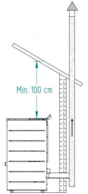
A clearance to combustibles of 100cm must be maintained above the stove see Fig 5
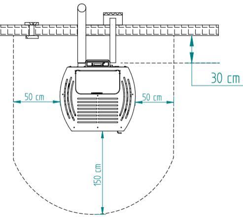
A clearance to combustible of 50cm must be maintained to either side of the stove , 30 cm to the rear and 150 cm to the front of the stove see Fig 10
In the event that the product is installed in a non combustible recess, clearances for servicing,must be provided, 200mm to the rear and 300mm to the sides.
VENTILATION/COMBUSTION AIR
The process of combustion requires oxygen, and therefore air. When in operation, the stove draws air through the 50mm diameter intake pipe at the rear of the appliance. The external air can be connected through a straight pipe of maximum length 60cm. Otherwise the appliance will draw air from the room in which case provision must be made for the air requirement providing an air vent in the room. Poor combustion may result if the room is insufficiently ventilated.
A room containing an appliance (other than a room sealed appliance) should have a permanent ventilation opening of free area of at least: 6,500 mm² where air permeability is greater than 5.0 m³/(hr.m2), 8,150 mm² where air permeability is less than 5.0 m³/(hr.m2).
Where a flue draught stabilizer is used the total free area should be increased by 300 mm2 for each kW of rated output.
If the stove is located in a room containing another air using appliance, it is essential to provide ventilation equivalent to the sum of the air requirement for all appliances. the stove should not be installed in the same room as an extractor fan.
FUEL
The appliance is suitable for use with wood pellets certified to EN 14961-2 grade A1 with a diameter of 6 mm and a length that can range from 10 to 30 mm.
As fuel, pellets are completely environmentally friendly, as they are made entirely of natural wood, without glue or other chemical compounds. Pellets have a high calorific value (4.7 to 5.3 kW/kg), and low moisture content.
IMPORTANT: Pellets must be stored in a dry place. Use only good quality pellets, without sawdust.
IMPORTANT NOTICE: The small quantities of sawdust normally present at the bottom of the bags should not be emptied into the tank, but should be held inside the bag while pouring the pellets carefully so that the sawdust remains inside.
If sawdust accumulates in the tank, it should be removed periodically with a vacuum cleaner (with the door open and disconnecting the power plug from the electricity supply), to prevent it entering the loading system and causing serious malfunctions.
Fig. 6
Fig. 5
Using the Pellet Stove
Before starting up the unit, please check the following:
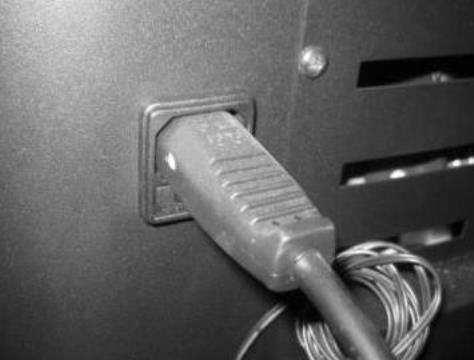
Ensure the unit is properly connected to the power mains using the 230V AC power cable.
Check if the pellet reservoir is supplied with pellets. Inside the pellet reservoir is a safety grid to prevent users from reaching the worm screw.
The combustion chamber of the stove and the door are built in steel sheet painted with high temperature paint, releasing fumes during the first ignition due to the cure of the paint. Avoid touching the equipment during the first burn so as not to leave permanent marks on the paint because it s going through a plastic phase during its curing process.
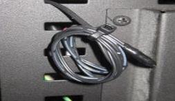
The stove has a probe for measuring the room temperature. This probe is attached to the grid on the rear panel For a good reading of the room temperature, avoid the contact between the end of the probe and the unit surfaces. You may also attach the probe to the wall beside the unit.
Remote Control
The infrared remote control allows the user to turn the unit ON and OFF, control the fan airflow and increase or decrease the unit's power level.

Fig. 7
Fig. 8
Fig. 9
Button
Mode/ Esc
Menu / OK when flashing
Function
Toggle between manual and automatic mode / escape or exit menus .
Access menus / ok -accept value
On / OFF Start unit when it is off , stop unit when it is on, Resets error messages
Minus sign - scroll menus to te left, increase and reduce the fan speed, increase or reduce the set-point temperature
Plus sign + scroll menus to the right increase or reduce the heat output
Selecting the Manual or Automatic Mode
To select the operating mode, press the Mode key to select Manu for manual mode or Auto for automatic mode.
Manual mode : In this mode, the unit will operate at the heat output selected using the "-" key, ranging between 1 (minimum fire ) and 5 (maximum fire)

Auto mode: In this mode, the unit is turned on at maximum power until reaching a temperature 1ºC above the selected temperature (set point temperature). After reaching the selected temperature, the unit switches to the minimum operating power. The set-point temperature can be set between 5 and 40ºC by pressing the "-" key. The "+" key allows the user to set the fan speed between 1-5 or to A for automatic operation.

Setting the Date and Time
Setting the date:
press the Menu key twice until Day and Time is displayed.

Press set to see the following menu:

To set the year press set . The display starts to flash. Press the + or - key to select the desired year and then ok to confirm.
Press "+" to scroll to the next menu. The Month is displayed.

To set the month press set . The display starts to flash. Press the + or - key to select the desired month and then ok to confirm
Press "+" to scroll to the next menu. The Day number is displayed. This is the date / day of the month.

To set the Date press set . The display starts to flash. Press the + or - key to select the desired date and then ok to confirm
Repeat the same steps to set the Day of the Week ,Hour and minutes.
Setting the sleep Timer
This option is only displayed on the menu when the stove is on. Press the menu button until day and time is displayed , then press the ok button twice which will scroll to the right to show the display as below
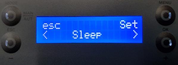
Press "set". The display starts to flash. Select the desired time using the "-" and "+" keys. After choosing the time, press "ok" to confirm. Press esc when finished to get back to the normal display
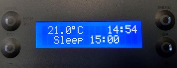
The display will then switch between the normal screen and a screen similar to above showing the current time and the sleep time at which the stove will switch off.
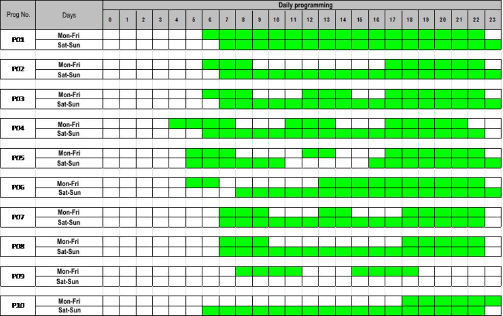
Setting the Programmer.
The unit is equipped with a timer that allows the unit to be turned on or off at specified times.
This can be set up by loading one of 10 preset profiles in the software P01- P10. Alternatively the unit can be programmed manually with up to 6 on/ off times per day.

When the unit is set to switch on and off using the programmer the display will flash between the on/ off screen and a screen similar to above.
To enable the timer press set . The enable menu is displayed. The timer may only be activated after setting the configurations, as shown in the following paragraph..

To activate the Timer mode, press Set the display starts to flash. Press the + or -" key to select On or Off and then Ok to confirm. Press the "+" key to scroll to the "Load profile" menu.

There are 10 weekly programmes available on the Timer see fixed timer schedules at the back of the manual . The selected programme runs from Monday to Friday and from Saturday to Sunday.
Press set ; the display starts to flash. Press the + or - key to select the desired programme and then press ok to confirm. Press the "+" key to go to menu "Reset".

Press the "+" key to go to menu "Reset".This menu allows you to delete any programme settings. To do this, press "set". The "Confirm" appears. Press "set" again to confirm that you want to delete the settings or "esc" to exit.

Alternatively the unit's programmer lets you choose from 6 different programmes for each day of the week.
To set up programmes P1 to P6 , select the desired programme using the - and + keys, and press set to select. The "P1 Enable" menu appears.
To run a user set program P1 the timer/ chrono must be enabled and also the program must be enabled

Press "Set" again and when the display starts to flash, press the "+" or "-" keys to select "On" or "Off". Press "ok" to confirm the selection. Press the "+" key to go to the "start time.

To set the starting time for Programme P1, press set . The display starts to flash. Press the + or - key to select the time and then press ok to confirm. Press the "+" key to go to the P1 . Stop" menu.

To set the stopping time for Programme P1, press set . The display starts to flash. Press the + or - key to select the time and then press ok to confirm. Press the "+" key to go to the "Air Temperature menu.

To set the set point temperature for Programme P1, press Set . The display starts to flash. Press the + or -" key to select the desired temperature, followed by Ok to confirm.

To set the operating power level (1 to 5) of Programme P1, press Set . The display starts to flash. Press the + or -" key to select the desired power level (1 to 5), and then Ok to confirm. Press the "+" key to go to the "Days" menu.
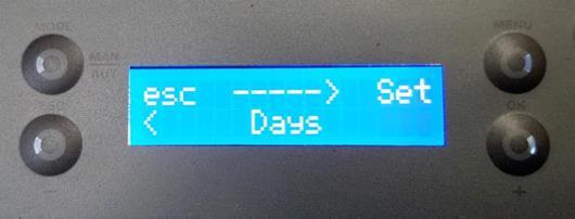
To select the days of the week that you want P1 Programme to run, press "set" and then select the day of the week using the - and + keys. Press set . The display starts to flash. Select "On" or "Off" using the "-" and "+" keys. Press "ok" to confirm the selection. Press the "esc" key to go to the "Days" menu. Press the "esc" key again to go to the "program " menu. Press the + key to move on to the next menu.
Repeat the steps to set up Programs P2 to P6 or as many as are required.
Once the programs are set remember to
User Information
To access the user information.
press set twice and then press + until User Info is displayed
press set to acess the User info then scroll through the following list of parameters using the + and.
Control board code.
Security code
Display code Parameters
Functioning time/ run hours
Service time/ time since last service
Service time/ time to next service
Carrying out/ current status
Exhaust Fan -Rpm
Consumption pellets- kg/hr
Fumes/ Flue gas temperature
Pellet feed time
Ignitions number
Setting menu,
To access the settings
press set twice and then press + until settings is displayed.
press set to acess the settings then scroll through the following list of parameters using the + and -
Language
Eco mode
Back light
Remote control
ºC/ºF
Combustion recipe
Language
To select the language, press set
Using the + or - keys, select the language. En English
Eco mode
When the ECO mode is enabled at the same time as the Thermostat feature, the unit will operate at maximum power until the thermostat opens contact (NO). The unit then will operate at minimum power for a pre-set period of time (Shutdown delay time: factory setting: 20 minutes).
Once the pre-set time is elapsed, the unit shuts down. At the start of the Shutdown phase, another timer for a different pre-set period of time is triggered (Start-up delay time: factory setting: 20 minutes), that will make the unit enter the activation phase, when the thermostat closes contact (NC)
Start-up delay time (Delay time On): The delay time that elapses between the moment the thermostat closes (NC) until the unit is activated.
Shutdown delay time (Delay time Off): The delay time that elapses between the moment the thermostat opens (OC) until the unit starts to shutdown.
Note: When using the feature for the first time, you must press the On/Off button in the display. To enable the eco mode, press set . The display starts to flash. To activate the eco mode, press "set". The display starts to flash. Select "On" or "Off" using the "-" and "+" keys. Press "set" to confirm the selection.
To Select back light , press set . The display starts to flash. Press the "+" or "-" key to select the time for the screen to light up, or select "On" to keep the light permanently on. Press ok to confirm.
Remote Control.
This feature enables and disables the remote control, when the user wants to operate the unit's thermostat remotely. Press "Set" and use the "+" and "-" keys to select the "On" or "Off" mode. Press "Ok" to confirm. Press the + key to go to the temperature units menu.
Note: Some TV remote controls share the same frequency as the unit s remote control, possibly influencing the unit's operation. If this is the case, it is recommended to disable the remote control feature.
ºC/ºF
To select ºC / ºF, press set . The display starts to flash. Press the + or - key to select ºC , ºF or Auto , and then ok to confirm.
Combustion settings.
This allows for adjustment of the pellet quantity and the air flow
Pellet
This feature allows the user to increase or decrease by 25% the pellet quantity during the start-up and power process. Press "set". The display starts to flash. Press "+" or "-" to increase or decrease (between -10 to +10), as required. Each unit must be multiplied by 2.5 to obtain the correct percentage.
Air
This feature allows the user to increase or decrease by 25% the rotation speed of the fume extractor during the start-up and power stages. Press set . The display starts to flash. Press the "+" or "-" key to increase or decrease (from -10 to +10), as required. Each unit must be multiplied by 2.5 to obtain the correct percentage. Press ok to confirm.
Technical menu,
The technical menu is password protected, the password is only provided to authorised technicians.
Operation.
Start up.
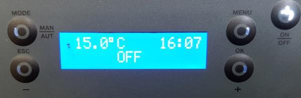
After loading the pellets into the hopper , press and hold the ON/OFF button for 3 seconds, to start the stove. During the lighting phase, the display will show the message Ignition (until this phase is completed. The pellets are fed through the supply channel to the burning pot (combustion chamber), where they will be ignited using an igniter. This process may take 5 to 10 minutes, depending on whether the worm screw used to push through the pellets has been previously filled or not. Once the ignition phase is completed, the message "On" appears on the display. The heating power can be adjusted at any time by pressing the power selection button for approximately 1 second. You can select from the five pre-set power levels that are available. The selected power is indicated on the display. The initial power status at each start-up will correspond to the power level set before the last stop.
Note Before starting the machine check that the baffle plate is correctly positioned.
Shut down.
To turn off the pellet stove is carried out by pressing the ON / OFF button for 3 seconds. The display will show shut down until full completion of this phase. The extractor will operate until the fume temperature of 64ºC is reached, to guarantee that all the material has been burnt.
Note
Do not shut down the appliance by isolating the electrical supply .


Fig 10 shows the baffle position as viewed from inside the firebox. Item 1 on the picture highlights that the tab on the baffle must overlap down over the vermiculite lining at the rear of the firebox. Item 2 shows the gap to the front between the baffle and the body of the appliance, this should be approx 20mm
CO ALARM
The fitting of CO Alarms in the same room as the appliance is a compulsory requirement under current Building Regulations. For ROI an additional CO Alarm must be fitted either inside each bedroom or within 5 metres of the bedroom door, refer to Building Regulations Part J. Further guidance on the installation of a carbon monoxide alarm is available in BS EN 50292:2002 and from the alarm manufacturers instructions.
Fig. 10
Assembly Instruction for Installing the control panel, side panels , hopper cover and grill.
Installing the Casings on K100. Before installing the casings you should check immediately whether the packing is complete and in perfect condition, possible damages or parts missing must be reported before proceeding with installation. Following procedure describes how to install the casings for the K100 unit.
Equipment required.
Philips Screwdriver, PH2 10mm open ended spanner.
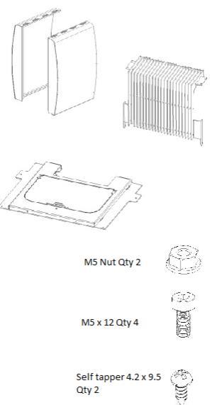
Required parts

Place the display located inside the pellet hopper on the back of the unit, as shown in Figure 12. To perform this task, slightly unfasten the screws located in the rear of the unit. When securing the display it may be necessary to adjust the height.
Note
When installing the display handle it with care because there is a cable from the central unit of the stove connected to it. Disconnecting this cable will prevent the proper operation of the equipment.
Fit the lower holes on the side covers (figure 13) to the guides located at the bottom of the machine (Figure 14).


c) Next, attach the side casing by sliding it downwards. During the assembly of the casing, make sure the flap on the top side (1) is placed overlapping the structure and, simultaneously, covering the rear side of the unit on the outside, as shown in Figure 15 & 16
Fig. 11
Fig. 12
Fig. 13
Fig. 14
d) Repeat the process described above for the other side panel and secure using four screws from the kit, two on each side, as shown in Figure 17

Secure the side panels to the back of the unit using 10 screws from the kit, as shown in Figure 18.

The cover is equipped with four guide pins (1) in the bottom to ensure its proper placement. These guide pins must be fitted onto the springs in located in the structure.
Note:
You may need to gently press the guide pins onto the structure to secure them.
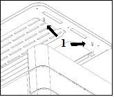

Fig. 15
Fig. 16
Fig. 17
Fig. 18
Fig. 19
Fig. 20
Installing the Casings on K300. Before installing the casings you should check immediately whether the packing is complete and in perfect condition, possible damages or parts missing must be reported before proceeding with installation. Following procedure describes how to install the casings for the K300 unit.
Equipment required.
Philips Screwdriver, PH2 10mm open ended spanner. 8mm open ended spanner. Hexagonal / allen key 4mm
Required parts
a)
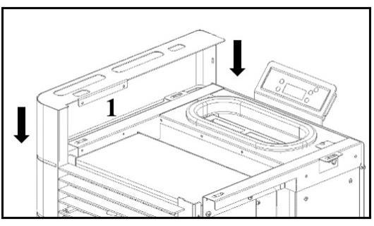
Fit the top plate as shown in figure 21. To ensure that the top is properly seated, it contains four pins on the bottom that should fit the springs in the frame.

Fit the front grille, matching the holes in the grille to the holes in the appliance (figure 22).

Fig. 21
Fig. 22
Fig. 23
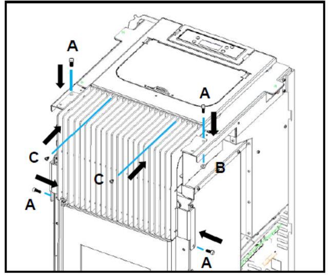
Fasten the upper part of the grill with two self tapping screws location C, fixed directly to the cover previously placed. Then fix with M5x12 screws at locations marked A and fix with M5x12 screws and M5 nuts at locations marked B, see figure 24.
Fitting Side Covers
When fitting the side covers, first fit the tabs, (note 1 fig 25) to the slots (note 2 fig 26) and then the studs 3 (note 3 fig 27) on the side covers to the spring clips (note 4 fig 28) on the chassis.


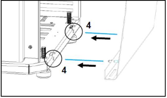
Fig. 24
Fig. 27
Fig. 26
Fig 25
Fig. 28
Pellet Reservoir / Hopper
To access the pellet reservoir, open the lid on the top of the unit by pushing down and sliding the clip top the left.

The reservoir will hold approx 15 kg on the K100 with the K300 holding approx 18kg to fill the hopper carefully cut the corner of the bag so the pellets can be poured into the hopper without spilling outside of the rubber seal. Do not pour dust into the hopper as it can impair the feed screw mechanism.
Glass Cleaning
The glass can only be cleaned when it is completely cold. It must be cleaned with a suitable product in accordance with the instructions for use and care must be taken to prevent the product from reaching the sealing cord and painted metal parts - so as not to cause undesired effects. The rope seal is fixed with adhesive so any contact with water or any other liquids must be avoided. If using a glass cleaning spray, apply the product to a cloth first as opposed to applying it directly to the glass.
Daily Maintenance/ Ash Removal
The stove requires careful maintenance see label on the hopper lid , it is recommended to keep a maintenence log as outli ned in maintenance log section The most important thing is to periodically remove the ashes from the pellet burning chamber For your convenience, you may use a household vacuum cleaner The cleaning operation must be performed after burning approxi mately 30kg of pellets.

Prior to cleaning, the stove must be turned off and allowed to cool to prevent injury.
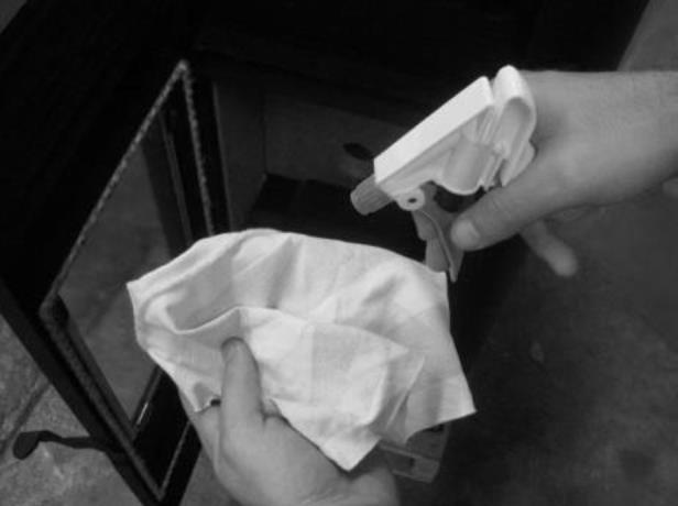
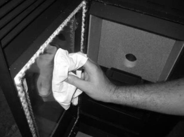
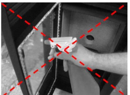
Fig.32 & 33 Correct cleaning of the glass. Cleaning the glass:
a) moisten a soft cloth with liquid; b) clean the glass using the cloth
Fig. 31 Incorrect cleaning of the glass
Fig. 31
Fig. 30
Fig. 29
Fig. 33
Fig. 32
Weekly Maintenance/Cleaning the flueways.
To perform this maintenance, pull the cleaning bar from the heat exchanger see fig 34, then open the door (b), vacuum the ash and clean the burner (c).


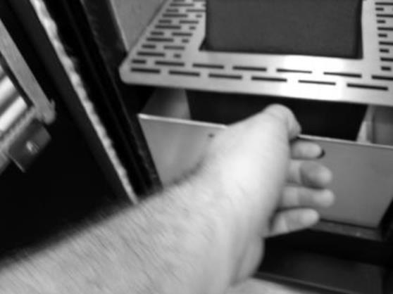

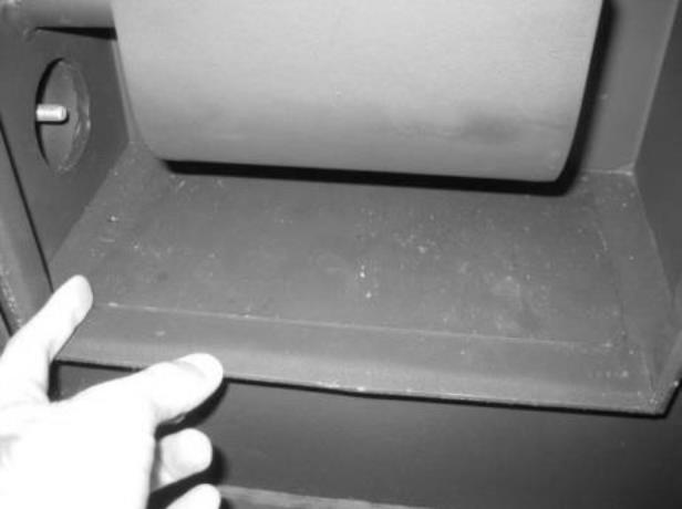
There is a trapdoor hidden under the ashpan which can be removed for cleaning.
Fig. 35A
Fig. 34
Fig. 38
Fig. 37
Fig. 36
Fig. 35B Grate removal

Clean the area under the trap door with a vacuum cleaner , carefully replace the trapdoor in the correct location. It is critical that this component is returned to the correct location and seated properly.
Additional cleaning
Note The frequency of maintenance depends on the quality of the pellets burned.
Additional cleaning should be performed for every 600-800 kg of pellets burned. Remove the side covers, to access the side lids of the combustion chamber. To clean the interior of the unit, remove the screws


Removal of cleaning access panels K100
Removal of cleaning access panels K300
Fig. 39
Fig. 40
Fig. 41
Fig. 42
Following removal of the panels . Using a 2025mm wide 80cm long steel brush,thoroughly clean the channels and vacuum clean the residue.
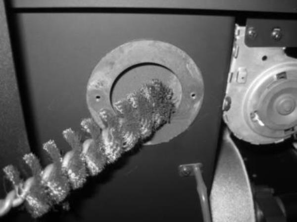

If you noticed that the flue gas extraction is not effective, we recommend cleaning the interior of the extractor with a vacuum cleaner, as shown in figure 46. This operation should be performed, on an annual basis at a very minimum, more frequent cleaning may be required.
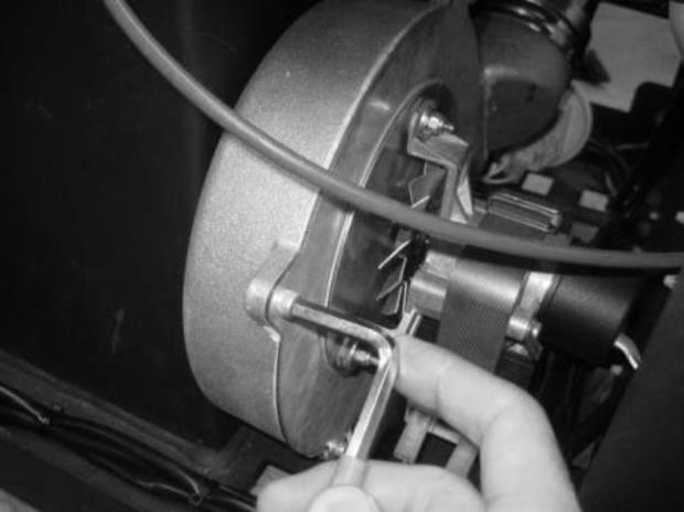
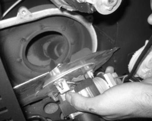
Fig. 43
Fig. 46
Fig. 45
Fig. 44
Note
A service warning on the display (maintenance due) indicates that the unit has exceeded 2100 operating hours. In this case, the client must perform the unit's maintenance procedure (following the instruction on the Technical Manual). Once this procedure is completed the hour meter may be reset, to clear the waning message. This message does not impact the normal operation of the unit. It is simply a warning.
Note
The errors can be reset only when the error information is flashing on the display. To reset the error, press the Mode button once while displaying the error.
Maintenance Plan and Log
To ensure the proper operation of the unit, maintenance operations must be performed, as described in sections Weekly cleaning through to Additional cleaning of this Instruction Manual . There are specific maintenance tasks that must be performed by authorised technicians only. Please contact the person responsible for installing the unit. To make sure the warranty remains valid, the maintenance operations performed on this unit must comply with the frequency requirement specified in the manual, and the service technician must fill and sign the maintenance log.
Service / Cleaning schedule
Empty the ashpan after each burning of 30kg of pellets.
Vacuum the burner and under the trapdoor etc on a weekly basis.
Brush and vacuum all residue from side channels after each burning of 600-800kg of pellets.
Full service by Technician including all of the above and cleaning of the flue and flue fan etc must be carried out on an annual basis, full details are provided on the label fixed to the hopper cover.

Troubleshooting guide
Note
When triggered, all the alarms below cause the machine to shutdown. The alarm must be reset and the unit restarted. To reset the unit, press the On/Off button for 10 seconds until the alarm sounds.


Fixed timer program schedules