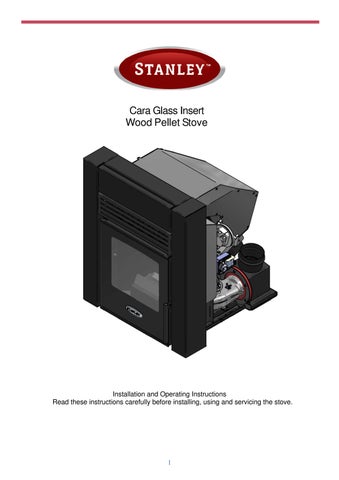
Cara Glass Insert Wood Pellet Stove
Installation and Operating Instructions
Read these instructions carefully before installing, using and servicing the stove.
Thank you for purchasing a Waterford Stanley Wood pellet Stove.
Please read this manual carefully and retain it for future reference. These products fulfil the requirements of the Construction Products Regulation and have been approved with the CE conformity mark;
WATERFORD STANLEY bears no responsibility for any damage to the stove if it is installed by non-qualified personnel;
WATERFORD STANLEY is not responsible for any damage to stoves not installed or used in compliance with the instructions included in this manual;
All local regulations, national and European standards, must be observed when installing, operating and servicing the stove;
Whenever you need assistance, you should contact your stove’s supplier or installer. You must have the wood pellet stove serial number located over the identification plate.
The product must be commissioned by a Waterford Stanley approved service engineer.
CONDITIONS OF WARRANTY
Your Stanley pellet stove is guaranteed against any part that fails (under normal operating conditions) as detailed in the following table with timelines specified from the date of installation of the appliance. If the stove is not installed within six months of date of purchase, the warranty will commence six months from the date of purchase.
Warranty Period Parts Covered (Parts & Labour unless Stated)
Up to 1 Year
Up to 2 Years
• Refractory materials (supply only)
• Rope seals, glass seals and cement seals.
• Surface Finish on Seno models.
• Grates and fire bars.
• Ceramic glass is covered for Thermal breakage (supply only).
• Rust (if reported before installation)
• Aesthetic Damage (provided reported on date of receipt)
• Electrical components under normal operation.
• All external finishes (excluding impact damage or damage caused by overfiring). Pictures of damage must be submitted to WS Service Department.
All warranty claims must be reported to the Waterford Stanley Service Department and must be submitted with the product serial number (located on the data plaque at the rear of the product), date of purchase, proof of purchase (if requested) and details of the specific nature of the problem.
The warranty is given only to the original consumer/purchaser only and is non- transferable. The appliance must be installed by a suitable qualified person and installed as per the requirements of the manual. Failure to comply with the Installation requirements or Building Regulations will void your warranty. Waterford Stanley reserve the right to replace any part due to manufacturing defect that fails within the warranty period under the terms of the warranty. The stove must be used for normal domestic purposes only and in accordance with manufacturer's operation instructions.
LIMITS OF LIABILITY
The warranty does not cover:
• Special, incidental or consequential damages, injury to persons or Property, or any other consequential loss.
• Any issue caused by negligence, misuse, abuse or circumstances beyond Waterford Stanley’s control.
• Any issue with wear and tear, modification, alteration, or servicing by anyone other than an authorized service engineer.
• Installation and operational related problems such as draught related issues external to the stove, inadequate venting or ventilation, excessive flue offsets, negative air pressure caused by insufficient burning of improper fuel.
• Damage caused to the stove while in transit.
• Discolouration due to over firing, damage caused by impact, damage to baffles caused by over firing and fading of surface finish on casting.
• Stress fractures on bricks.
• Rust on parts unless reported prior to stove being installed.
• Aesthetic damage, rust & missing parts on stoves purchased off display.
• Electrical components where voltage variations are in excess of 10% of nominal 230V
Note: Adequate clearance must be maintained around the appliance to ensure the ease of part removal in the possible event of their damage/failure. Waterford Stanley are not responsible for any costs incurred in the removal of items installed in the vicinity of the appliance that must be moved to facilitate a part replacement.
2 Settingthelanguage.
Should the language revert to the default language
Press the set button until the display shows “ REGOLA DATA-ORA”
Then press the + button above the temperature symbol 6 times, then one press of the – below the temperature symbol.
Then using the + and - buttons adjacent to the flame symbol the language can be adjusted, followed by the set button to confirm your choice
3 Packagecontent
- Forced Convection Pellet Stove “Cara Glass Insert” 5.1 kw
- Installation Base Plate with Chimney adaptor
- Instruction Manual,
- Power cable
- Remote Control
- Pellet Push tool
- Glove.
- Carton for wifi kit with set up label, ( wifi kit is fitted to the stove.)
- Concrete fixing screws
4 Safetyprecautions
Waterford Stanley is not liable for any damages to the stove if the specified precautions, warnings and operating procedures are not followed.
Waterford Stanley stoves are easy to operate, and special attention was given to their components in order to protect users and installers against accidental damages.
The stoves must only be installed by a qualified installer.
This stove must be used according to its intended use as specified by the manufacturer. The manufacturer is excluded from all liability, by contract or by tort, caused by injury to people, animals or property arising from misuse or faulty installation or servicing.
After removing the packaging, verify the contents to check their integrity and completeness. If the content of the package fails to correspond to that indicated in point 1, contact the retailer from whom you purchased the stove.
All the stove's components guarantee its operation and energy efficiency and should only be replaced with original parts provided by an authorised Stanley retailer or service engineer.
The stove should be serviced at least once a year by the Stanley service engineer or more frequently depending on usage of pellets. This manual is provided with the product. Please keep it close to the stove.
4.1.1 SafetyRecommendations
• Make sure you fully read and understand this instruction manual before using the Cara Glass Insert pellet stove as a biomass heating stove.
• The pellet stove is not intended for use by children or persons with reduced physical, sensory or mental capabilities, or lack of experience or knowledge, unless they are under supervision or have been instructed concerning the use of the stove.
• Do not touch the stove if any part of your body is wet or humid.
• Do not tamper with safety or adjustment features without the manufacturer's authorization;
• Do not cover or reduce the size of the vents at the installation area;
• The pellet stove requires a clear space around the stove for proper combustion, so possible air tightness of the location or any existing air extraction sources in the room may prevent the correct operation of the stove.
• The stove must have adequate air supply to support combustion.
• Do not leave the packing materials near children;
• During normal operation, the stove's door must not be opened;
• Some parts of the stove will become hot during normal operation, so avoid direct contact with parts such as the door handle and glass;
• Check the existence of any obstructions on the fume duct before turning on the stove after a long period of inactivity;
• This pellet stove is intended for residential use in protected areas. Safety systems may turn off the stove. If this occurs, contact the technical assistance. In any circumstances should you attempt to interfere with the safety systems;
• The pellet stove is a biomass heating stove equipped with an electric fume extractor. The occurrence of any power failure shut off the exhaust fan, the product must be connected to a naturally vented chimney/ flue to exhaust the remaining flue gases.
• During operation, NEVER turn off the Pellet stove by disconnecting the electric plug. The fume extractor is electric so disconnecting the power plug will prevent the extraction of combustion flue gases;
• Your stove must be disconnected from the mains for servicing. Before doing this, the stove must be totally cooled down (if operating before);
• Never touch the interior of the stove without disconnecting it from the power mains;
Tests performed using wood pellets with a calorific value of 4.8 kWh/kg. The above information was obtained during tests performed at independent laboratories accredited for pellet stove tests.
Note.
This product is specifically designed for installation in a non combustible masonry fireplace
Before installing, please perform the following steps:
• Upon receipt, check that the product is complete and that there are no signs of damage. Any damage or defects should be checked for prior to installing the product. If there are defects, please notify Waterford Stanley service department
• Remove the instruction manual from the package and hand it over to the client.
• Unbox the stove as described in section 3.1.1Unpackingofthestove
• The stove is equipped with a base upon which it slides to get into place.
• The Base has a chimney adaptor attached that has to be connected to the chimney duct of the installation.
• The Base plate will be installed first in the fireplace opening where the Stove will be installed.
• The Base plate has a hole pattern as it appears on the drawing below.
• Align the triangles located on the base plate with the front edge of the fireplace as seen in the drawing above:
• Use a straight edge to align the centre of the triangles and the front edge of the fireplace.
• Drill the base as necessary and fix with the screws provided
• When the stove is pushed in the frame will align in this location
Align with the front of the fireplace
• Using the proper fastening material that is included, attach the base to be floor securely
• When placing the base plate, make sure it is levelled and stable.
• Connect the flue, the stove requires an 80mm diameter flue connection.
• For safety reasons provide the Insert with a dedicated electrical connection. That will make sure that the power is turned off when the stove is pushed in or pushed out of the fireplace
• The Electrical connection is on the left side of the stove looking at it from the front.
• With the main power of the network switched off, attach the power cable of 220VAC to the stove and turn the switch to the ON position.
• Use only a grounded electrical connection to ensure the longevity and safety of the appliance.
• Put the Stove on the beginning part of the base making sure that it is in the middle of the base plate
• Carefully slide the stove in until the special Alignment Triangle tool is aligning with the front part of the base plate as shown in the drawing below.
7.1.1 Installation clearances
7.1.2 Hearth requirements
The fireplace that the stove is placed in must be constructed of fire proof non-combustible material. The floor must be capable of supporting weight of the appliance and any associated installation.
7.1.3 Installationofductsandfumeextractionsystems:
• The exhaust pipe must have been designed for this purpose, in compliance to the location requirements and in accordance with any applicable regulations.
• The exhaust pipe must be assembled to allow cleaning and maintenance of the pipe at inspection points
• Under normal operating conditions, the combustion gas flow should create a draught of 12 Pa one meter above the chimney neck.
• The stove must not be installed in a shared chimney.
• Pipes outside the heated area must be suitably insulated.
Waterford Stanley supply a flue kit
This can be purchased under the code ACPFLK
Flue Kit contents
1 Adaptor to fit the stove,
2 80mm diameter flexible flue liner for use in flues up to 8 metres in length
3 Chimney terminal/ cowl with both a bird guard and storm protection.
The installation must be completed with a storm cowl with a bird guard recommended for use with pellet stoves.
The termination of the flue must be at least 60cm above the apex when within 60cm oof the apex measured horizontally otherwise it must be at least 1 metre above the roof measured vertically.
Failure to comply with these requirements may prevent the correct operation of the stove. Follow all the instructions presented on the diagrams.
The pellet stove stoves operate with the combustion chamber in vacuum, so it is necessary to have a fume exhaust pipe to extract combustion gases properly.
AllmaterialusedtofluetheproductmustcomplywithcurrentBuildingregulations.
Insulation:
Windproof terminal: A windproof terminal must always be installed to avoid the backflow of flue gases. Draught in the chimney. All installation must guarantee a draught of 12 Pa (0.12mbars) measured when hot and at the maximum power.
7.1.4
Ventilation
The stove must have adequate air for combustion and the room must have adequate air for ventilation, adequate air supply must be provided in line with building regulations. The Cara Glass Insert Pellet stove is designed in such a way so that the air supply is through the front openings under the door and from around the stove. These openings under the door and around the stove must stay open at all times. No construction must be made around the stove that will result in blocking the air passageways.
This product should not be installed in the same room as an extractor fan. A test should be undertaken where the product is installed in a room adjacent to a room with an extractor fan verifying that there is enough air flow for the pellet stove to work properly.
If you do not use the stove for a long time, check it to make sure that the flue pipes are clear before lighting the fire.
Fig 6 Fig 7
8 Fuel
The Pellet Stove must be operated exclusively with wood pellets. No other fuel may be used.
Use only pellets certified by standard Premium DIN plus & EN plus A1, with a 6mmdiameter and measuring between10and30mmlong
The pellets must not have a moisture content in excess of 10%. To guarantee a good combustion, the pellets must maintain these characteristics so they should be stored in a dry place.
The use of different pellets will reduce the efficiency of the stove and cause poor combustion. Youshouldalwaysusecertifiedpelletsandmusttestasamplebefore buyinglargebulkloads.
The physical/chemical properties of the pellets (i.e. the calibre, friction, density and chemical composition) may vary within specific tolerances and according to each manufacturer. Please note that this may cause alterations to the feeding process and, consequently, the need for different doses (more or less pellets).
The stove allows the dose of pellets to be adjusted throughtheusermenu.
Warning : The stove must NOT be used as an incinerator
Recommendations
Before starting up the stove, please check the following:
• Guarantee that the stove is properly connected to the power mains using the 220-230VAC power cable.
• Check to see whether the pellet reservoir is supplied with pellets. Inside the pellet reservoir is a safety grid to prevent users from reaching the worm screw.
• Ensure that before each lighting the Combustion Pot is clear.
• Make sure the stove is put in place according to the instructions and that the Insert is pushed all the way in on the base until the front two indicators have aligned. That indicates that the fan has connected to the chimney adaptor properly.
The stove's combustion chamber is made from steel plate and painted with high temperature-resistant paint, releasing flue gases during the first burning sessions due to paint curing.
Figure 8 – Electric power plug.
9 ControlpanelOperation
9.1.1 Functionsofthedisplaybuttons
SET
This button is used to confirm or to enter a selected menu.
AUTO
Use this button to choose between the weekly thermostat or manual operation.
ON/OFF
Use this button to switch the pellet stove on and off. Also use this button to exit a menu.
Temperature
Use these buttons to set the desired temperature, navigate through the various menus and change settings.
Power
Use these buttons to select the power at which the stove should operate. These buttons are also used to navigate through the various menus and change settings.
9.1.2 Startingupforthefirsttime
Carry out the following actions for starting up the pellet stove for the first time:
• Ensure that the pellet stove is installed correctly and as described in the previous sections.
• Fill the tank with pellets or check whether the tank is filled with pellets.
• Check that the combustion pot is placed as far back as possible and that the glow plug is in front of the hole in the combustion pot.
• Check that the door is securely closed.
The pellets will pass through the supply channel to the burning basket (combustion chamber), where they will be ignited using a heat resistor. The display will be showing the message “Ignition Starting”. This process may take between 5 and 10 minutes, depending on whether the worm screw used to push through the pellets has been previously filled with fuel or is empty.
9.1.3 Ignition
Start the stove by pressing and holding the ON/OFF button until you hear a beep.
The pellet stove indicates: “StartingIgnition”.
The pellet stove will start and complete the following steps: Cleaning/preheating.
During this phase, the glow plug starts to glow, and the combustion pot is cleaned. Loadingpellets
During this phase, pellets are added until a fire starts in the combustion pot. The blower will slow down. Ignitionandstabilisation
After ignition, the flue gas temperature will rise and the stove will recognise this as a fire. The stove will now enter the stabilisation mode for a few minutes, and the stove will supply fewer pellets to allow the fire to slowly start.
Upon completion of the ignition phase, the sign Heat Manual should appear on the display accompanied with
Temperature “Ta” which is the ambient temperature.
Temperature “Ti” which is the Intended Temperature of the space where the stove is installed.
Power Level “P” Representing the Power Level Currently Used by the Stove.
By Pressing one of the “+ “ or “ – “ Buttons for Power Regulation, the selected power is indicated on the display. The initial power at each start-up will correspond to the power level set before the last stop.
The Intended Temperature can be adjusted by pressing the “+ “ and “ – “ buttons with the thermometer in between them.
The heating power can be adjusted at any time by pressing the “+ “ and “ – “ buttons with the flame between them, indicating power selection.
Five Power levels can be selected, 5 being the highest Heat Production.
The Power Level the Stove is using can be different than the Power Level that is Selected.
Thatmayhappenwhen:
• The Ambient Temperature is higher or equal to the temperature selected as Intended Temperature. In this case the stove automatically selects Power Level 1
• The Fumes Temperature is higher than the allowed temperature on the Selected Power Level. The controller for safety reasons automatically chooses a lower Power Level.
Note! Observe the following recommendations when using the stove for the first few times:
• The curing process of the paint is complete after the stove has been lit several times. During this curing process, vapours and odours may be released during the first few times of use.
• Start by using the stove at a medium power a few times so all mechanical parts can settle, and the paint can cure. This will increase the life of the stove.
• Properly ventilate the room several times after and during the first times of use.
• The first start-up of the pellet stove may take longer than usual. Because the Auger has not yet been filled, it takes longer for the pellets to reach the combustion pot. It may be that it takes too long for the pellet stove and an error message appears (Error1).
In this case, make sure the combustion pot is empty, press and hold the ‘ON/OFF’ button for a few seconds to clear the alarm and restart the pellet stove using the ‘ON/OFF’ button.
9.1.4 Stop
The stop sequence of the stove is started by pressing the start/stop key for 3sec. Until this phase has been completed, the display will show “Cooling Starting”. The extractor will remain active until the fume temperature drops adequately, to guarantee that all the material has been burnt.
9.1.5 Turningoffthestove
The stove should only be disconnected from electrical power after having cooled down completely and the fan being inactive. Make sure that the display indicates “StoveOff”
9.1.6 MENU
Use the menu to adjust various settings. Access this menu via SET . The following settings can be changed here:
9.1.7 SubMenu“SetDate-Time”
Set the date and time here. Use the power buttons to switch between the settings you want to change.
9.1.8
Use the temperature buttons to change the settings.
Use SET to save the changed setting.
SubMenu“WeeklyProgr.”
This is where you set the timer for the entire week. Below is a picture of the menu. We will provide a step-by-step explanation of what you are required to set. Refer to the above for details on how to proceed with the settings.
F01
This is the program number. You can set up to 15 different programs. MF
MF has been used in the example. This means the same setting from Monday to Friday. You can also set SS for Saturday and Sunday. It is possible to choose per day separately.
07.00
This is where you can set the time, for example, at what time the stove is to carry out the selected setting. 21°
This value is the pre-selected desired temperature. In the example, this means that the stove has to heat up to 21°C and then starts to modulate.
P2
This is the mode required for the stove to burn until the desired temperature is reached. ON
You can choose between ON and OFF to indicate whether the stove should start up (ON) or turn off (OFF) on the days and times that you have set according to the above steps. Enabl.
The example shows ON. Indicate whether you want to use this program (F01) (Enable) or not (No. A). This is also where you activate and deactivate the programme, as you activated it according to the above steps. This is not the same as switching the stove on and off, because this is set at ON or OFF as above.
9.1.9 SubMenu“Thermostatmode”
9.1.10
Use this menu to select the thermostat control for the stove to follow. It should be set to ‘stove thermostat’. Other functions are not in use.
SubMenu“StoveParameters”
Use this menu for setting three different values: The pellet auger, the blower and the convection fan. By default, these values are set to 0%. You can adjust these values between -50% and +50%.
Note! Adjusting the stove has a major impact on the operation of the pellet stove. Do not change the values by too large intervals; instead, consult your dealer.
PelletCharging
You can increase or decrease the quantity of pellets here. Pellets have their very own properties, involving length, type of wood, compression, etc., and you may need to make some adjustments to your pellet supply. This will be adjusted as necessary during commissioning.
SmokeDrainage
This is where you set the amount of combustion air. In addition to the pellet supply, a suitable oxygen ratio is of main importance for good combustion. This will be adjusted as necessary during commissioning.
FanEnvironment
This is where the speed at which the convection fan should run is set. These values only apply if the stove is equipped with a convection fan. Increase this value if, for example, the stove requires additional cooling or if you wish to disperse the heat more quickly. It is not recommended to decrease this value to prevent insufficient cooling of the stove.
9.1.11 SubMenu“SystemLog”
All Errors that have occurred to the appliance, are saved in this Menu.
9.1.12 SubMenu “Selectlanguage”
In this menu it is possible to select the language of the Menu.
9.1.13 SubMenu“Parametersset”
This menu is used for changing recipes of Pellets or different Solid Fuel (Not available in this model)
9.1.14 Lockingkeys
This is where you can lock the Keys of the display by pressing the following buttons for 20 seconds:
Temperature minus and the Power minus
Repeat this operation to release blocking.
9.1.15 ECOstop
Set the ECO stop if you wish for the stove to completely switch off as soon as the desired temperature has been reached. Be aware that this may have consequences for the life of your igniter. In addition, and for ECO stop in particular, it is important that you regularly check the combustion pot for Ashes that might accumulate and will not allow for a proper ignition.
Set the ECO stop as follows: Simultaneously press SET and the power minus for more than 5 seconds
until PARAMETERS appears on the screen. Press SET twice until it says ‘Parameter 1 Value (..)’.
Use the power button plus to navigate to parameter 62.
As a default, this value is set to 0, meaning that the ECO stop is deactivated. This is where you set the temperatures at which the stove should switch.
Working example:
If you set this value to 2 and set the desired temperature to 20°C, the stove will switch off at 22°C and on at 18°C. Set a large value to prevent the stove from switching on and off continuously.
You can set the value using the temperature buttons.
Confirm the set value using SET
10 Resetcomponenttest/servicemessage
This is where you can test the components and read sensor values. Enter this menu by pressing SET and the Power button plus for more than 5 seconds.
The stove now displays ‘TESTCOMPONENTI’. Press SET. You can test the components only when the stove is switched off and says “StoveOff” on the display.
10.1.1 Testingthescrewconveyormotor
Go to ‘Motore Coclea’ to test the Auger motor. Press and hold SET to test whether the motor runs. This is also where you can read the RPM of the stove. It is indicated in 3 digits and you get the Rpm by multiplying with a factor of 10 (100RPM = 1000RPM). The RPM indicated is that of the electric motor, not that of the Auger itself. The Auger rotates at maximum 1 RPM.
10.1.2 TestingtheFan
Go to ‘Aspiratore Fumi’ to test the Flue Gas Fan. Pressing SET should cause the fan to run at full power for as long as the button is pressed. You can also read the RPM. Maximum RPM is approximately 2850.
10.1.3 Testingtheconvectionfan
On the menu Vent. Ambiente is where you test the convection fan.
10.1.4 TestingtheIgniter
Press and hold SET to test the Igniter. The Igniter should become hot.
10.1.5 Readingtemperaturesensors
Go to the display with ‘Ta Tf Th’.
The value Ta indicates the measured Ambient temperature.
The value Tf indicates the measured Flue gas temperature. The value Th does not apply here.
10.1.6 Readingandresettingoperatinghours
Go to the screen with ‘Ore Lav. Da Ass’ to determine the number of hours your stove has been burning. Read the total amount of operating hours under OreLav. These hours cannot be reset. Find the hours you can reset under DaAss. This is the amount of hours from the last Service. If this amount exceeds 1200, the pellet stove displays a service message. Following maintenance, reset the service message in this menu as follows:
Simultaneously press and hold both temperaturebuttons until the hours jump to 00000. The service message disappears from the display.
Note!Presstherightbuttons! Simultaneously pressing the power buttons will cause the parameters to reset to the settings of the software manufacturer. These settings are completely different from the pellet stove parameters.
10.1.7 Readingthefirecycle
Read the current operating timers of the stove and the duration of the cycle involved right now. Go to the ‘Vc Vf Va Pi Time’ screen. This is where you can read on the Pi position (related to Power 1 to 5) at which the stove currently operates.
11 WifiConnectivity
11.1.1 WifiModule
The stove comes equipped with an on board Wifi module. For the connection sequence please see the video, scanning the following QR code:
11.2 ConnectionExplanation
The wifi unit is factory fitted to the stove, while the wifi unit carton is supplied in the stove with the necessary label to ease the pairing process with the wifi in the house.
In the remote mode, the EVO Remote Wi-Fi module is connected with a cable to the stove. Furthermore, the module is connected to a router with a wireless connection. The router allows the Wi-Fi module to connect itself to internet.
A smartphone, connected to internet with a mobile connection or a Wi-Fi private network, can communicate with the EVO Remote Wi-Fi module, and so you can control your stove wherever you are.
11.3 Necessarymaterialsandinformation
To configure the EVO Remote Wi-Fi module in the remote mode, you must have:
• An EVO Remote Wi-Fi module with its Device Code available on the back of the module
• A device with Wi-Fi connectivity (Smartphone, PC or tablet)
Moreover, you have to know the following information:
• Name of the Wi-Fi network (SSID)
• Password of the Wi-Fi network
• Security of the Wi-Fi network
11.4 Attention
◆ The EVO Remote Wi-Fi module DOESNOT support the network with spaces in the SSID AND/OR spaces in the password. In the case, the module will be no longer useful in remote mode. You’ll need to change the name and/or the password of the Wi-Fi network.
◆ The EVO Remote Wi-Fi module supports only the network with the following security:
◦ WEP
◦ WPA1
◦ WPA2
◦ WPA mixed
◆ It is only possible to connect the product with a 2.4 GHz Wi-Fi connection. If you are connected to a 5 GHz connection and you have a 2.4 GHz connection available, please connect to the 2.4 GHz network.
11.5
Registration
To use the EVO Remote Wi-Fi module in the remote mode, a free registration is necessary in order to receive the parameters needed for the smartphone App.
To register yourself, go to the following web page using a PC or a smartphone: https://duepigroup.com/en/prodottiduepi/dpremote-iphone-and-android-app/
At the end of the page a registration form is available. Insert the correct data in de specified fields and press the button “Submit”.
ATTENTION! The registration is only mandatory if you want to use the module in the remote mode. If you plan to use it only in local mode, you can avoid the registration. However, the registration is always possible, even after some time from the purchase. For the configuration of the App, go to section7
For further information, please contact dpremote@guepigroup.com
11.6 EVORemoteWi-Fimoduleconfiguration
ATTENTION! The following operations must be done near the Wi-Fi module (not more than 3-4 meters away from the module)
1. Connect the EVO Remote Wi-Fi module to the stove. Keep holding the “WS” button for 1-2 seconds, then the red and green lights will blink alternatively.
2. Connect your Wi-Fi device to the private network of the Wi-Fi module (WiFly FZX or similar). With your smartphone, PC or tablet you can do this by following these steps: “Settings” → “Wi-Fi” → “Find network” → “Connect”
3. Once you are connected, the green LED light will stay on solid state, the yellow LED light will blink and the red LED light will be off. In case you don’t see this condition, please reset the module by pressing the “R” button and try the previous steps again.
Now open a web browser.
4. In the address bar, insert the following text: http://config or 192.168.4.1
5. When the page is loaded, you will see the following page. If the page does not load, please delete your browser history (including cookies) and try again.
Add the following data:
Username: user
Password: user
Press the LOGIN button.
6. The following screen will appear:
7. Now select your Wi-Fi network. If your network is not in the “AvailableAccessPoint”, press the button “Scan Networks”. If your network still does not appear, please check your network connection.
8. Enter your password in the “Password” field (if it is an open connection, you do not need to enter a password).
9. Press “Save&Exit”.
Confirm by pressing “Ok”.
10. You can close the webpage at this point. If the module does not restart itself, press the “R” button for a few seconds. Once restarted, within a few minutes the module will connect to your chosen Wi-Fi network. This situation is visible in the green LED light, that stays on solid. In case this does not happen, try to repeat the module configuration and carefully review the inserted data, or refer to section8 for troubleshooting. The table below shows the module functionality based on the LED status.
11. LEDStatus
On Solid OFF OFF
On Solid Fast Blink (once a second) OFF
Slow Blink (once every 2 seconds) OFF OFF
Fast Blink (once a second) OFF OFF
On Solid OFF Fast Blink (once a second)
The Green and Red LED blink casually
The Green and Red LED blink alternatively
11.7 DPRemoteAppconfiguration
The module is not powered.
Check the connection between module and stove.
The module is connected to the DPRemote App and is communicating correctly. No operations, the module is working correctly.
The module is connected to the DPRemote App and is communicating correctly. No operations, the module is working correctly.
The module is connected to the router but doesn’t have an internet connection yet.
The module is waiting on a router connection.
The module has disconnected itself from the router.
The module isn't connected to the router.
After the pressing the “WS” button the module is generating a Wi-Fi network for its configuration.
If in few minutes the green LED doesn't stay on solid, try to reset the module and the router. Some settings could deny the module connection.
If in few minutes the green LED doesn't stay on solid, try to reset the module and the router. If the problem persists, check the router settings.
If in few minutes it doesn't reconnect automatically, reset the module and the router.
Reset the module and the router. If the problem persists, try to approach the module to the router and check if the settings of the module are correct.
If you aren't in the configuration phase, reset the module by pressing the “R” button.
To connect the smartphone to the EVO Remote Wi-Fi module, follow this procedure:
1. Check if you are connected to internet with a mobile connection or Wi-Fi;
2. Download the DPRemote App (or the “My DPRemote” App) from Google Play or the App Store, depending on what device you have;
3. Start the DPRemote application by pressing its icon on your smartphone:
4. At the start, press the icon on the top-right corner to enter in the settings:
5. Select the remote connection mode (remote):
6. Enter the data into the App as follows:
7. You can add 3 different pellet stoves to the App. Use 1 of the 3 available fields for the “DeviceCode”, you can find this on the back of the module’s box. Check the box next to the “DeviceCode” and “StoveName”.
ATTENTION! It is possible to insert up to 3 remote devices. The application will manage ONLY one device at the time, selected from the check-box nest to the fields.
ATTENTION! In the field “StoveName” you can insert only 15 characters; it’s an optional field of description.
8. Press the “Save” button to save the settings and return to the main page;
9. At this point, the application will try to connect to the Wi-Fi module. If the fields are filled correctly, you can control your stove with the following panels:
10. The application is now connected to the Wi-Fi module. If this did not happen, press the “R” button for several second to restart the module. The application I connected with the Wi-Fi module as soon as the green LED light is on solid. If this does not happen, re-configure the application and enter the correct data into the corresponding fields. See section8 for troubleshooting.
11.8
Troubleshooting
Q: The module does not power up itself.
A: Check if the module is connected correctly to the stove.
Q: After pressing the “WS” button, I can’t find the Wi-Fi module’s network. A: Try to shut down and power up the Wi-Fi on your device.
Q: I can connect the module, but while I’m entering my Wi-Fi network information, the connection was lost/disconnected.
A: The module waits for 120 seconds, after that it resets itself. Reset the module by pressing the “R” button for a few seconds, and try it again.
Q: I can connect to the module, but when I try to open its internet page, the module disconnects itself
A: Reset the module by pressing the “R” button for a few seconds and try it again.
Q: I can connect to the module, but I can’t open the internet page to configure it.
A: Try to delete the cache of the internet program you are using and reload the page. The way of doing this differs from program to program, check the website for modality. Generally you have to delete the “temp” data.
Q: The configuration page of the module is shown, but if I press the “RefreshList” or the “Save&Reboot” button, an error appears.
A: Try to delete the cache of the internet program you are using and reload the page. The way of doing this differs from program to program, check the website for modality. Generally you have to delete the “temp” data.
Q: After pressing “RefreshList” button, my network is no longer in the list.
A: Try to move the module closer to the router. Otherwise you can configure your Wi-Fi network manually by inserting the network name (SSID), the security and the password into the correct fields.
Q: When I press the “Save&Reboot” button, the page shows an error on the network name SSID.
A: The module does not support a network name and/or password with spaces. In this case you have to access the configuration of your router and change the name/password of your network.
Q: I have configured the Wi-Fi module, but it does not connect itself to the network and the green and red LED lights are blinking.
A: Check if the network data used are correct.
• Try to move the module closer to the router.
• Disconnect the module from the stove, wait a few seconds and reconnect it.
• See the table at section6.12, which shows the functionality based on the LED status.
Q: After the configuration of the DPRemote application, it shows me the following error:
A: Go to the settings (see section7). Check if the (right) DeviceCode is entered and the check-box next to the appliance is selected.
Q: After the configuration of the DPRemote application, it shows me the following error:
A: Check if the module has the green LED light on solid and if the red LED light is OFF. Check if the smartphone that you are using, is connected to the internet. Check if you have inserted the correct “DeviceCode”.
Q: I can’t find an answer in these FAQ’s.
A: Try to disconnect the module from the stove, wait a few seconds, reconnect it to the stove and repeat the configuration of the module and/or the application.
12 Maintenance
Generalmaintenance
Be sure to carry out regular maintenance and clean the stove as described in the following paragraphs to ensure a long life.
For(fire)safetyreasons,afullservicemustbecarriedoutbyqualifiedpersonnelaftereachyearofuseor1200 burning-hours
Before carrying our maintenance and cleaning, ensure that the stove is switched off, the plug has been removed from the socket and the stove has cooled down.
Never use corrosive or aggressive cleaning agents on external or internal parts. The use of these agents may cause to corrosion and damage, and the guarantee does not cover damage caused by this.
Have defective components replaced by your dealer or manufacturer.
12.1.1 Cleaning the Combustion Pot and Combustion Area
Clean the combustion pot and ashpan before each use. Cleaning the combustion pot is important for proper combustion. Failing to clean the combustion pot may clog the holes in the combustion pot and prevent the air from properly achieving combustion. This causes slagging. When cleaning, make sure no ash or pellets are left underthecombustionpot.
12.1.2 Cleaningtheglass
The glass may only be cleaned with the stove completely cold, while using an appropriate product as per the instructions for use. You should prevent the product from reaching the sealing ring and painted metal parts so that no undesirable oxidation occurs. The sealing ring is glued, so should not be exposed to moisture from water or cleaning products.
12.1.3 Cleaning of painted metal parts
Clean painted parts using a damp cloth. Do not use aggressive, corrosive or oil-based cleaning products, such as gasoline and alcohol.
12.1.4 Cleaningthecombustionchamber
It is important to vacuum out and empty the pellet stove on a regular basis. Use a vacuum cleaner suitable for ash extraction or a special ash vacuum cleaner.
12.1.5 Cleaningthepellettank
Clean your pellet tank every 3 months, depending on your pellets and consumption. If too much dust and sawdust accumulates at the bottom of the tank, the screw conveyor may be unable to load sufficient pellets or may get stuck, resulting in damage.
12.1.6 Maintenanceschedule
Parts/Period Beforeeach use every2days every7days every90days Annually& after1200 burning-hours
Figure 9 – Incorrect cleaning of the glass
Figure 10 – Cleaning of the glass: a) moisten a soft cloth with liquid; b) clean the glass with the cloth
12.1.7 Annual maintenance
The pellet stove must undergo a complete service every year or after 1200 burning-hours to ensure the preservation of your stove and your personal safety. The stove must be completely disassembled and the heat exchanger and the flues cleaned. This is important to prevent the stove from becoming clogged with ash and dust. This annual maintenance must be carried out by qualified personnel. Below are the various models and the parts to be disassembled for cleaning the flues and heat exchanger.
13 MaintenanceOperations
Turn off the stove and remove the burning pot.
Loosen the holding screws and take out the Burning Pot Holder. Remove the Lining From the Combustion Chamber.
Pull the Insert to the front and place it firmly on the ground.
Clean the Chimney connection box that is located on the base plate.
Remove the Exhaust fan.
The Fan can be removed just with the removal of 3 Bolts. Always inspect the Fan Gasket.
Clean the flue gas pathway under the fan. Clean the Room fan and inspect it for any damage.
The Igniter can be removed by simply unscrewing it from the Body of the Stove in case it need to be changed.
In the back of the tank when the stove is out of the fireplace you can find a hatch that allows you to access the Auger and clean the inside of the tank.
On the side of the chimney adaptor of the stove there is an M10x1.5 thread for emission testing during commissioning.
14 Problemsandsolutions
No image
Nothing appears on the display screen. There may be various causes for this. No power supply: Please Check whether the outlet has power. Check the fuses in your house. Check for a break in the cable.
Replace the power cord if there is a break in the cable. Check the fuse in the switch.
The switch shows a picture of a fuse; this is the location of the fuse.
Replace the fuse if it is broken.
If it has power supply, check the flat cable between the circuit board.
15 Faultreportsandsolutions
Important note: all alarms cause the machine to shut down. The alarm must be reset and restarted. To reset the stove press the “On/Off” button for 10 seconds until the alarm sounds.
15.1.1 ERROR1
ResetthefaultbypressingandholdingtheON/OFFbutton untilyouhearabeep.
This report appears if there is no ignition. The stove uses the flue gas temperature sensor to measure the temperature increase of the flue gases. If they do not rise quickly enough, the stove will present this error. A distinction must be made between No ignition with fire and No ignition without fire presence.
a. The stove shows no ignition or fire. Possible causes include:
- The glow plug is defective - A lack of oxygen. This may have several causes:
- The stove is clogged and needs maintenance
- The fan needs to be set on a higher setting, as there in not enough oxygen for ignition.
- The house has excessive under pressure. Examples of causes include: insufficient ventilation, a mechanical extraction exhaust system or extractor hood in the kitchen. You can check this by opening a window near the stove. If the stove ignites easier when opening a window, this demonstrates that there is too much under pressure in the house.
b. There is fire and ignition but the stove measures insufficient flue gas temperature.
Possible causes include:
- The flue gas temperature sensor is defective.
- Ignition is taking too long. One solution is to increase the speed of the fan and the amount of pellets during ignition.
15.1.2 ERROR5
Possible Cause: No pellet supply
The stove does not supply pellets.
Possible causes include:
- One of the safety sensors is switched on, this may be the maximum or the pressure monitoring device
- The Auger Motor is defective.
- The Auger Motor is stuck or blocked.
- - The tank is empty. Fill the tank with pellets.
15.1.3 ERROR6
This fault report has one of two causes:
- Component Pressure Sensor.
- Component Maximum Thermostat.
If the pellet stove becomes too hot, it malfunctions and indicates ERROR 6 on the display and the maximum thermostat has been triggered. The maximum thermostat will switch on if it measures over 110 Celsius on the inside of the stove. This may be caused by one of several reasons:
- The combustion is too hot. This may be caused by pellets with too much energy. The pellet supply must be adjusted downwards.
- The fan is unable to discharge sufficient flue gases and heat. Check that the combustion pot is clean. It may also be that the pellet stove requires maintenance.
- The pellet stove is covered. If the pellet stove is covered, it is unable to release heat.
If the Pressure sensor is the one causing the error, the Chimney might be blocked or the intake of the stove obstructed.
15.1.4 ERROR8
This fault report is triggered if the current is interrupted when the stove is in Operation.
You can reset this fault by pressing and holding the ON/OFF button until you hear a beep.
15.1.5 ERROR9
This fault report appears if the Encoder of the Fan is not reporting to the controller the expected RPM. Check whether the fan rotates or not. You can rotate the fan using the component test.
- If the Fan does not rotate, check that the fan is not blocked. Check the plugs and cables.
- If the Fan is rotating. Check the encoder, this is the sensor that measures blower RPM. Check this through the Testing Menu.
15.1.6 ERROR17
This fault report appears if the Encoder of the Auger is not reporting to the controller the expected RPM. Check whether the motor rotates or not. You can rotate the Auger motor using the component test.
- If the Auger does not rotate, check that the auger is not blocked and no foreign body is in the tank. Clean the tank and the internal part of the Auger to see if anything is blocking the rotation.
- If the Auger is rotating. Check the encoder, this is the sensor that measures the Motor’s RPM. Check this through the Testing Menu.
15.1.7 ‘Service’
This report indicates that the stove has been worked for 1200 hours. The stove indicates this as a reminder that maintenance must be carried out.
Readingandresettingoperatinghours
Enter the Testing menu by pressing SET and the Power Plus Button for more than 5 seconds.
The stove now displays ‘TEST COMPONENTI’. Press SET
To determine the number of hours your stove has been burning. Read the total amount of operating hours under OreLav These hours cannot be reset. Find the Work hours Service Interval under DaAss. If this amount exceeds 1200, the pellet stove displays a service message. Following maintenance, reset the service message in this menu as follows:
Simultaneously press and hold both temperaturebuttons until the hours jump to 00000.
The service message disappears from the display.
Note!Presstherightbuttons! Simultaneously pressing the power buttons will cause the parameters to reset to the settings of the software manufacturer. These settings are completely different from the pellet stove parameters.
15.1.8 It’sbecomingtoohotinthehouse
The temperature in the house rises further than you have set. This may have several causes:
- The stove has too much power in P1. Usually means that there is nothing wrong with the stove. You have set the stove at 20°C for example, but the temperature rises much further. Check whether the stove actually modulates back to P1. Keep in mind that a pellet stove produces between 2 - 3.5kW of heat in the lowest position. This means that in a small and/or well insulated room, the temperature will continue to rise as long as you leave the stove on. If you do not want the temperature to rise any further, make sure there is sufficient ventilation or switch the stove off.
- The room temperature sensor is measuring a very low temperature so the stove doesn’t stop working in high Power. If it is placed on the floor or against the wall, it measures the temperature of the wall or the floor instead of the room temperature.
- The room temperature sensor malfunctions. If this is the case, the stove will not properly read the temperature and respond according
Pin Description
DescriptionofJP1Connector.
1 Smoke temperature sensor input NTC 1K 200°C
2 GND
3 Room Temperature Sensor Input NTC 10K 25°C
4 External Chrono / GSM input
5 GND
6 GSM control output
7 Encoder Signal Input
8 +5V Encoder
Terminal Description
1 Pressure switch
DescriptionofJP2Connector.
2 Thermostat Safety Input
3 Not connected
Terminal Description
DescriptionofJP3Connector.
1 Exhaust Fan Motor Output
2 Room Fan Motor Output
3 Auger Motor Output
4 Igniter Output
5 230Vac Phase Input
6 230Vac Neutral Input and common mode Outputs
Terminal Description
1 Serial GND
2 Signal RX TTL
3 Signal TX TTL
4 +5V Serial
Terminal Description
DescriptionofJP8Connector.
DescriptionofJP9Connector.
1 Ext. Inp. (not used with Huba 401 sensor)
2 +12Vdc 50mA (Power Supply Huba 401 Sensor Red Wire)
3 Signal Input (Signal Huba 401 Sensor Yellow Wire)
4 GND (GND Huba 401 Sensor Black Wire)
NA Burnpot F01387AXX
NA ROOM TEMPERATURE PROBE (Optional Extra)
NA CABLE CONTROL PANEL
NA ENCODER CABLE AUGERMOTOR
NA ENCODER CABLE FLUE GAS FAN
NA Flue Gas Temperature Probe
G00550AXX
G00551AXX
G00552AXX
G00553AXX
G00560AXX