PORTFOLIO VARALIKARAJ SINGH
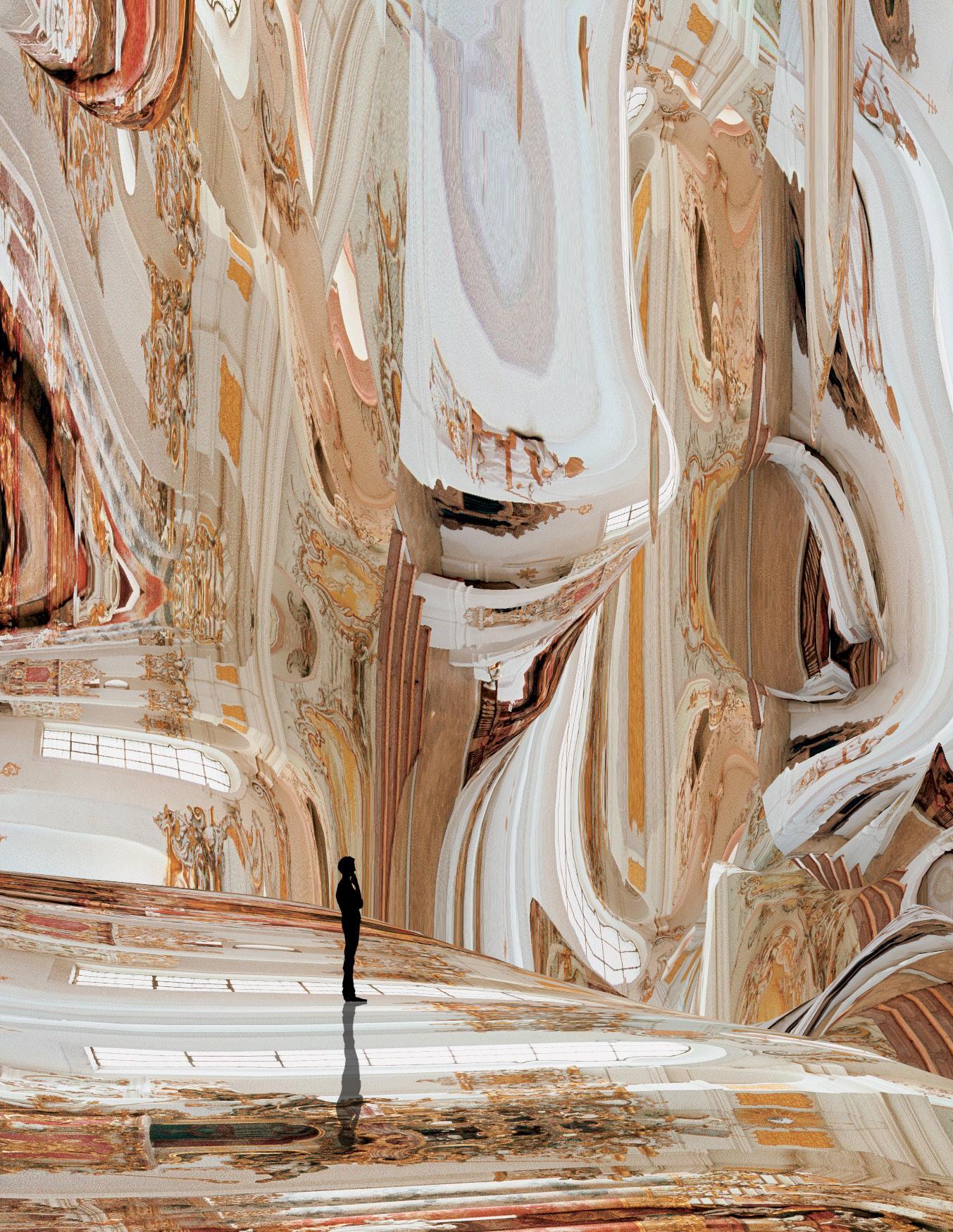
TABLE OF CONTENTS
6. IMMERSIVE ILLUSION
1. THE AVENUE
2. THE ATRIUM
3. THE WEST
4. THE WAREHOUSE
5. TAPSCOTT
THE AVENUE
Professional Work: STUDIOS Architecture
Supervisor: Melissa Duffy & Dana Hans
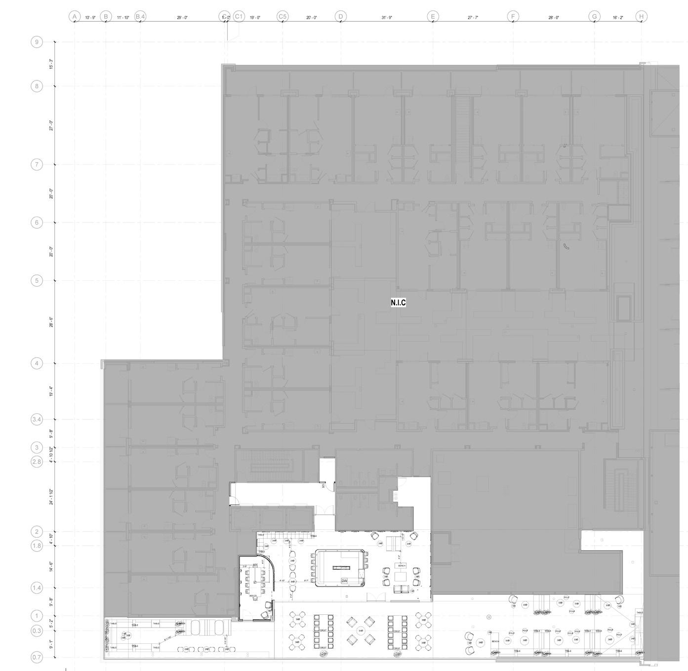
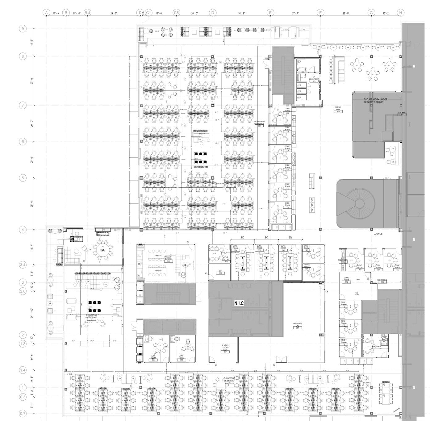
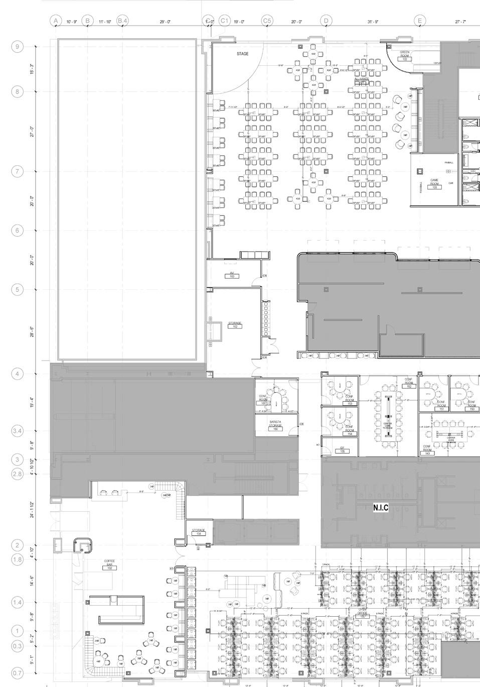
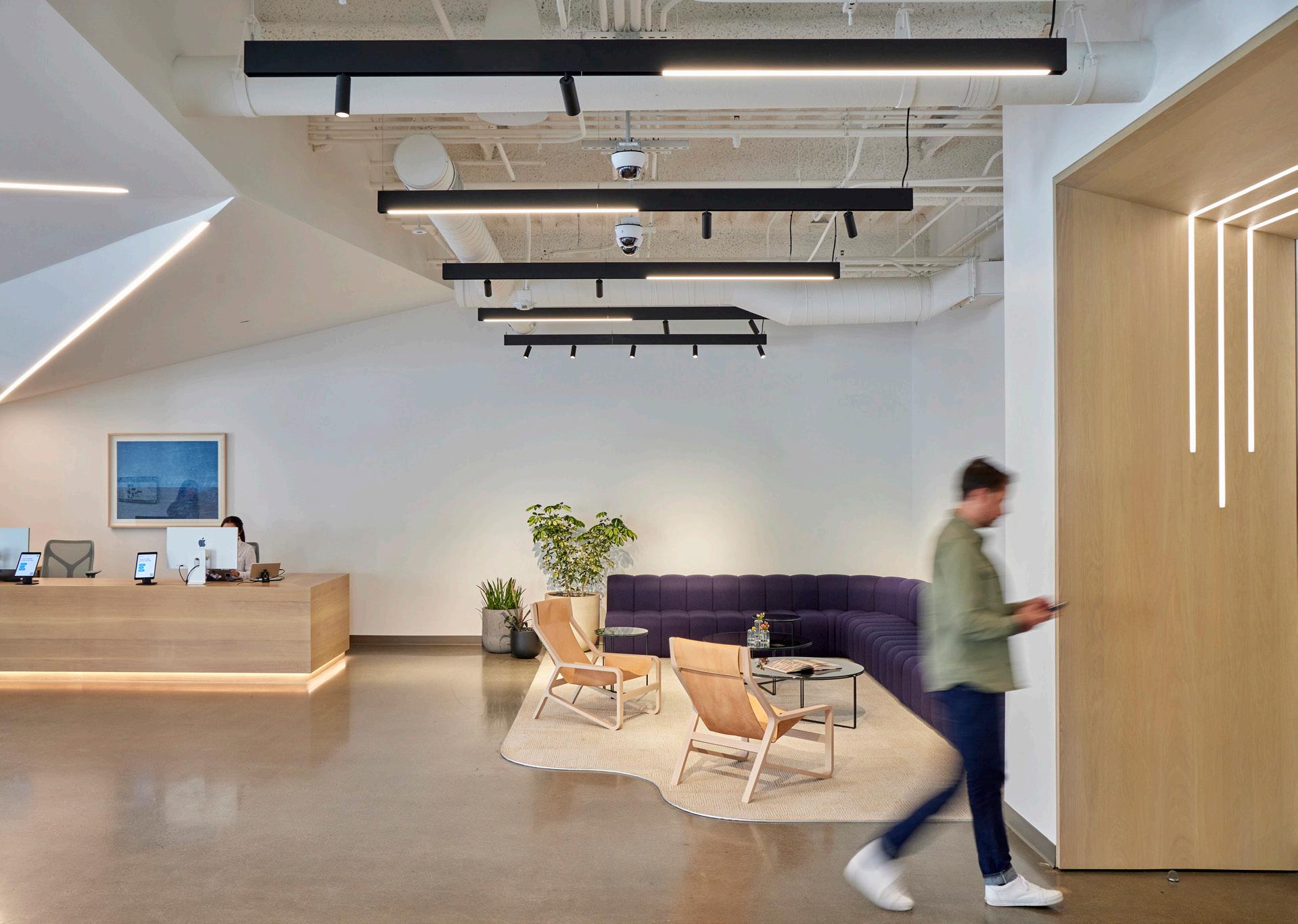
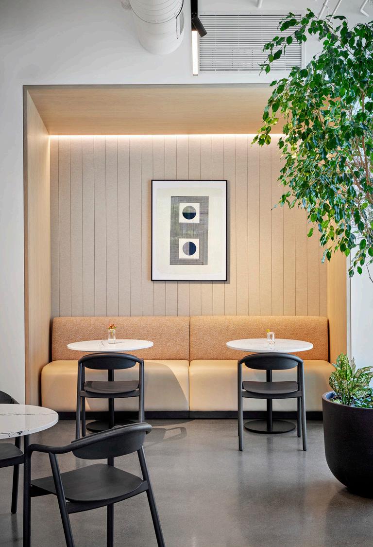
We infused the security technology company’s new space with hospitality-inspired community spaces and quiet lounges, and created energetic work areas throughout, connected by a spiraling three-story stair.
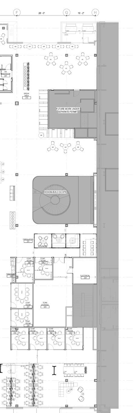
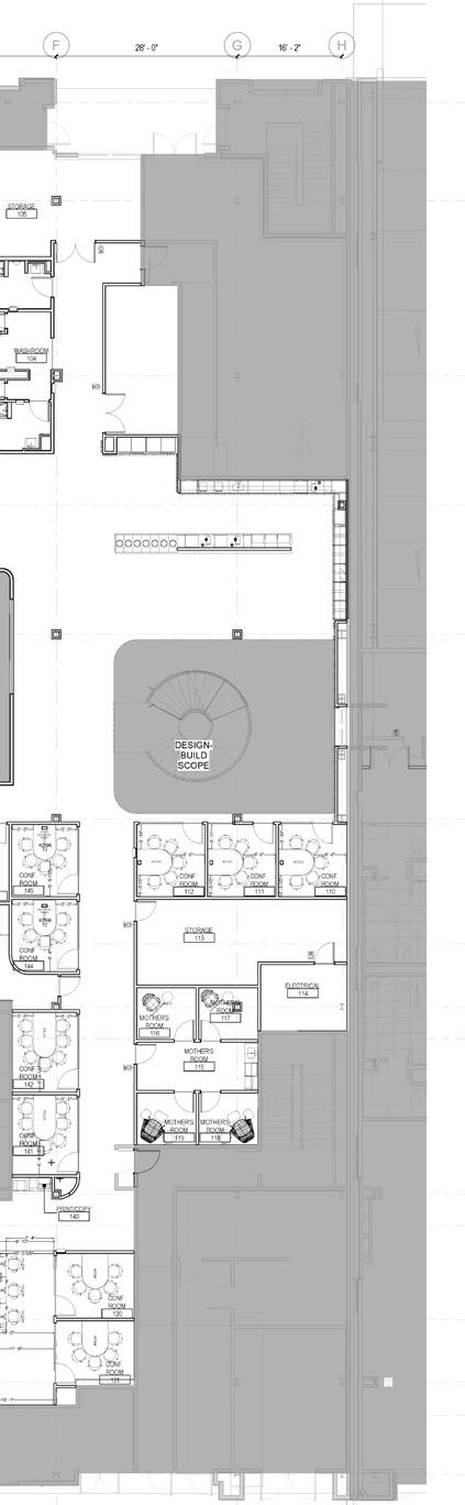
Proposed Plan - Level 4
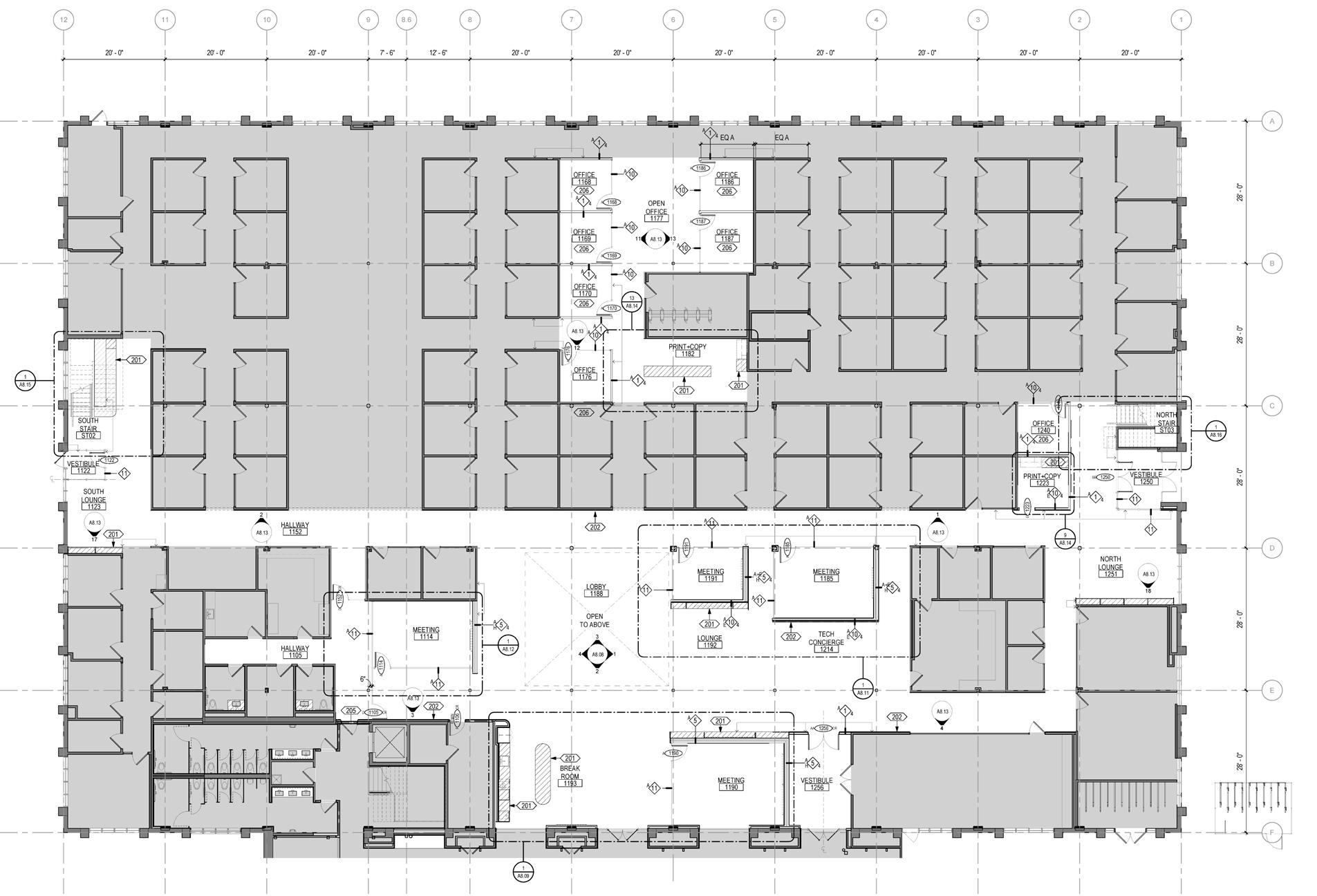
Proposed Plan - Level 2
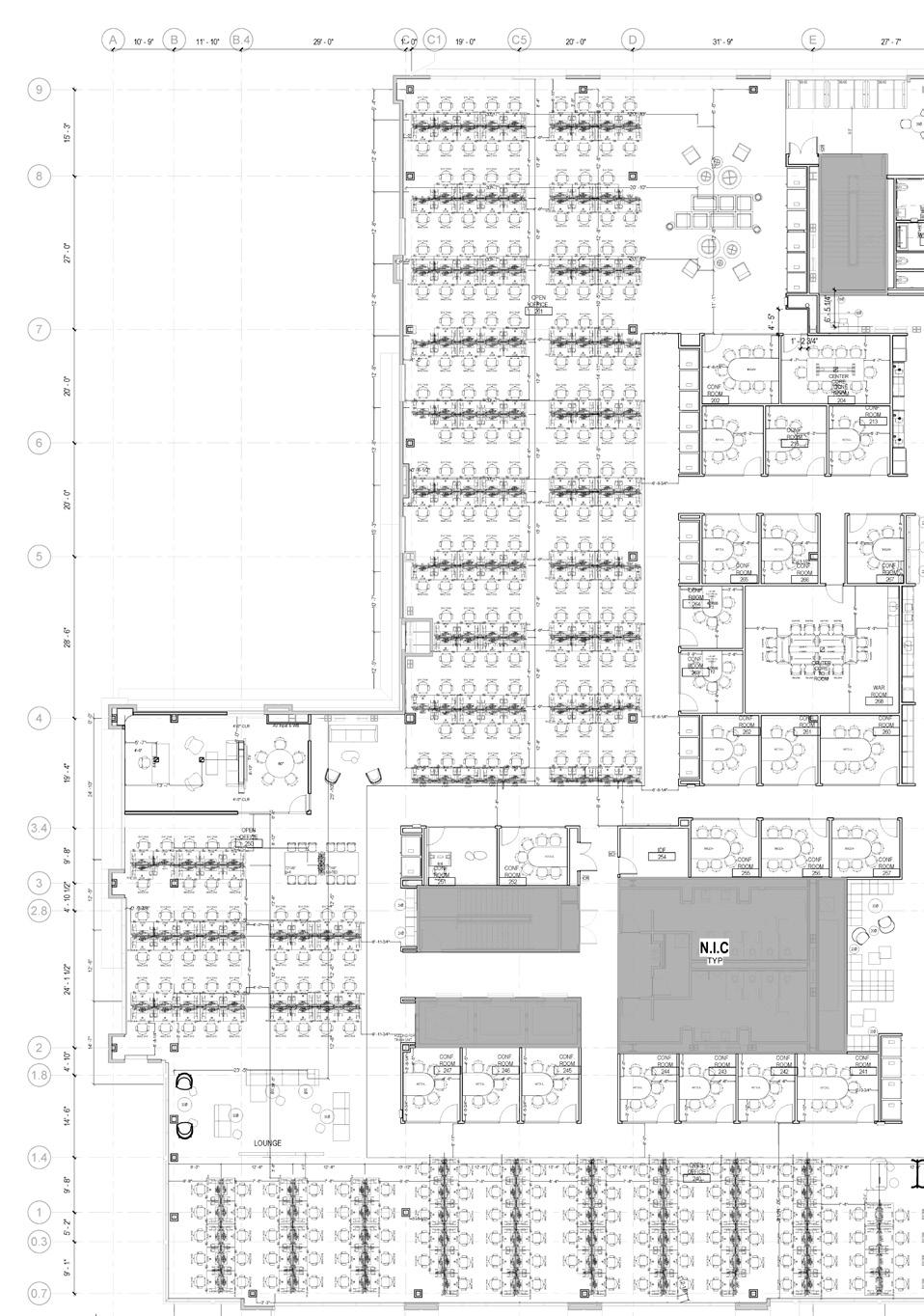
Proposed Plan - Level 3
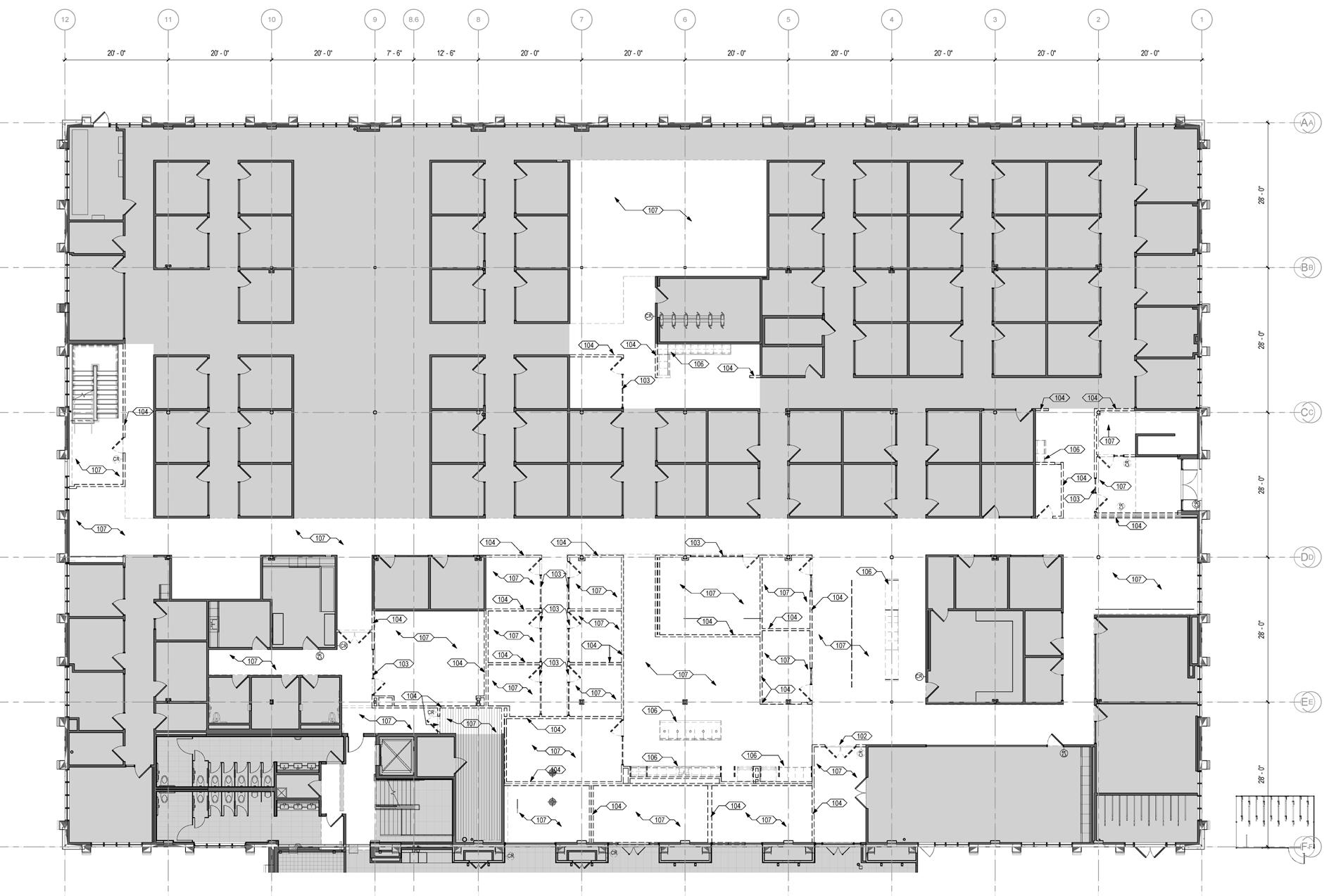
Proposed Plan - Level 1
Declaimer: All the drawings in this project belong to STUDIOS Architecture
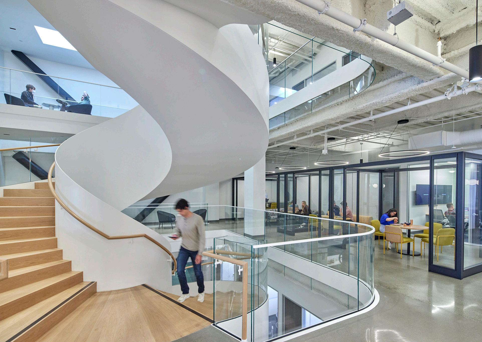
 Circular Staircase - Level 2
Lobby - Level 1
Circular Staircase - Level 2
Lobby - Level 1
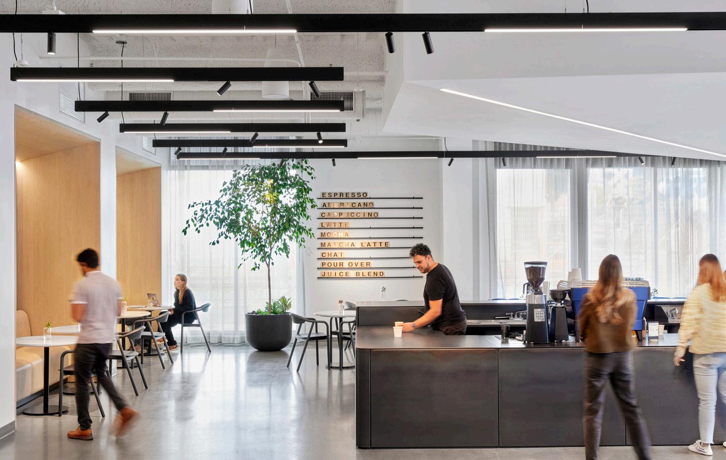
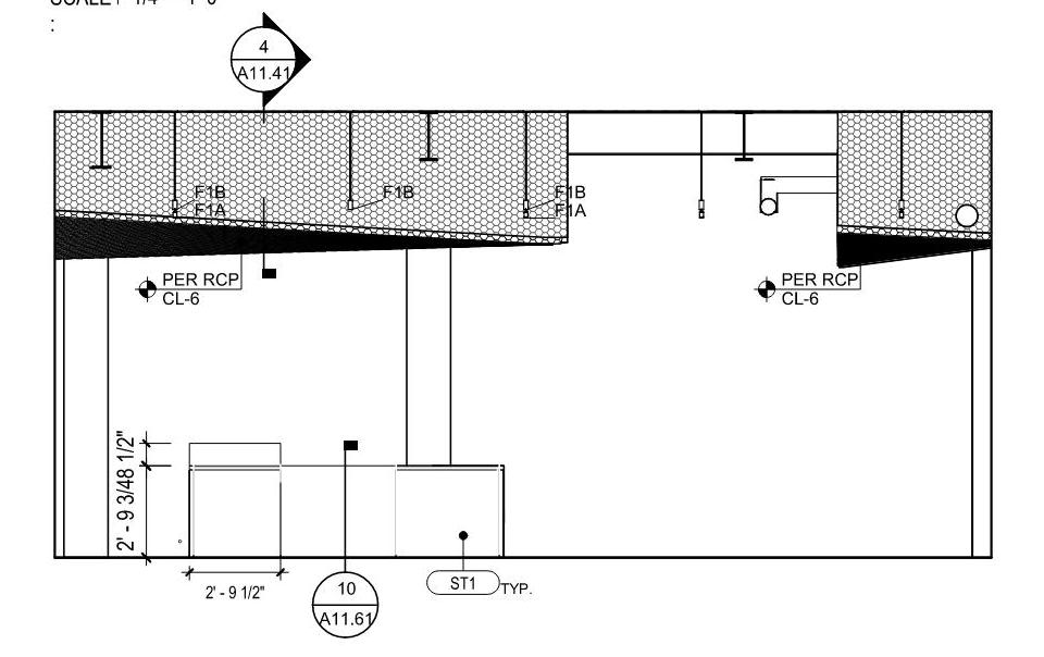
Enlarged Origami Ceiling - Level 1 - Coffee Bar
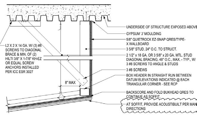
Origami Ceiling Section @ Bulkhead
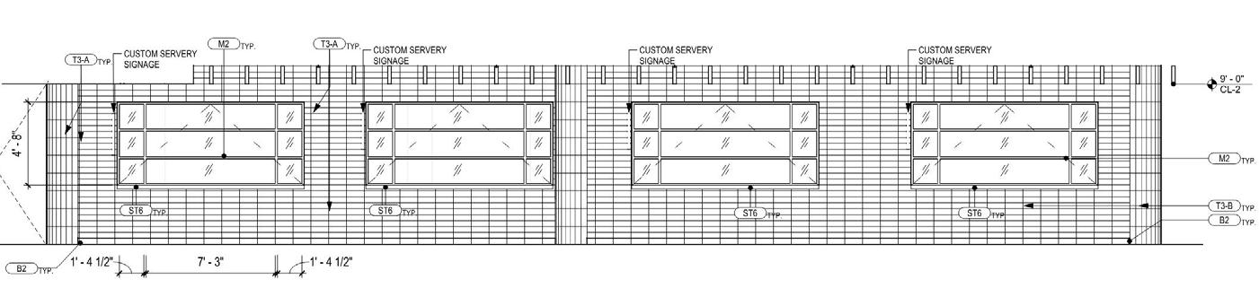
Enlarged Elevation- Cafe Servery - North Elevation
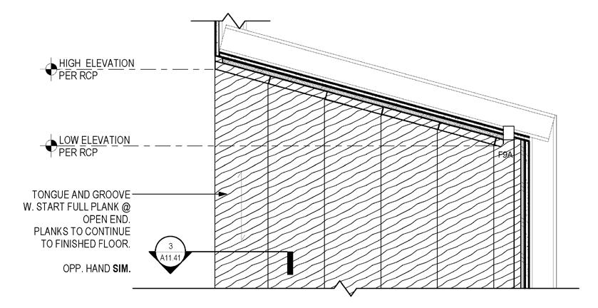

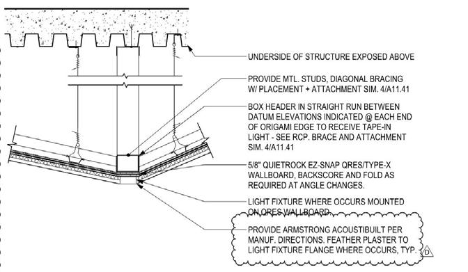
Origami Ceiling Section @ Tape in Light
Portal - Ceiling Detail @ Millwork Cubby
Coffee Bar West Elevation - Level 1 - Lobby
Enlarged Origami Ceiling - Level 1 - Lobby
Declaimer: All the drawings
in this project belong to STUDIOS Architecture
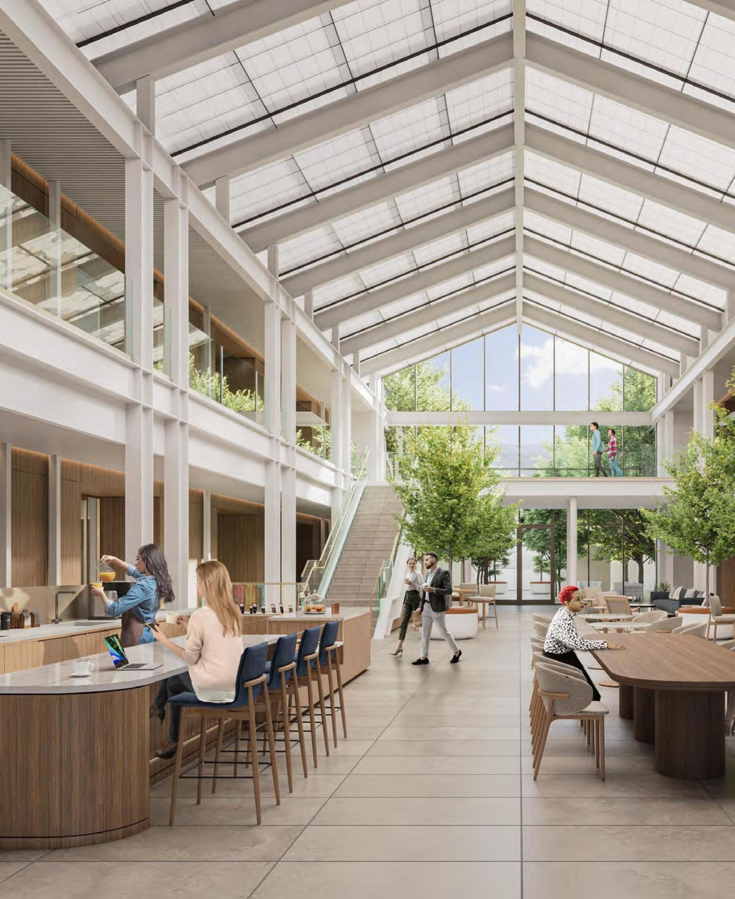
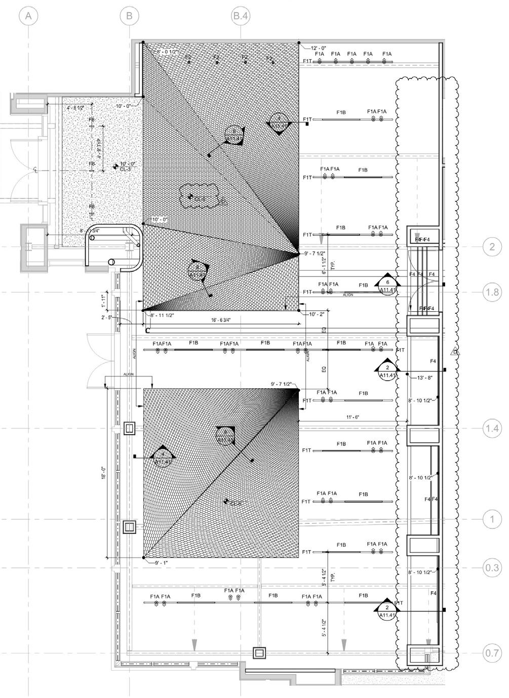
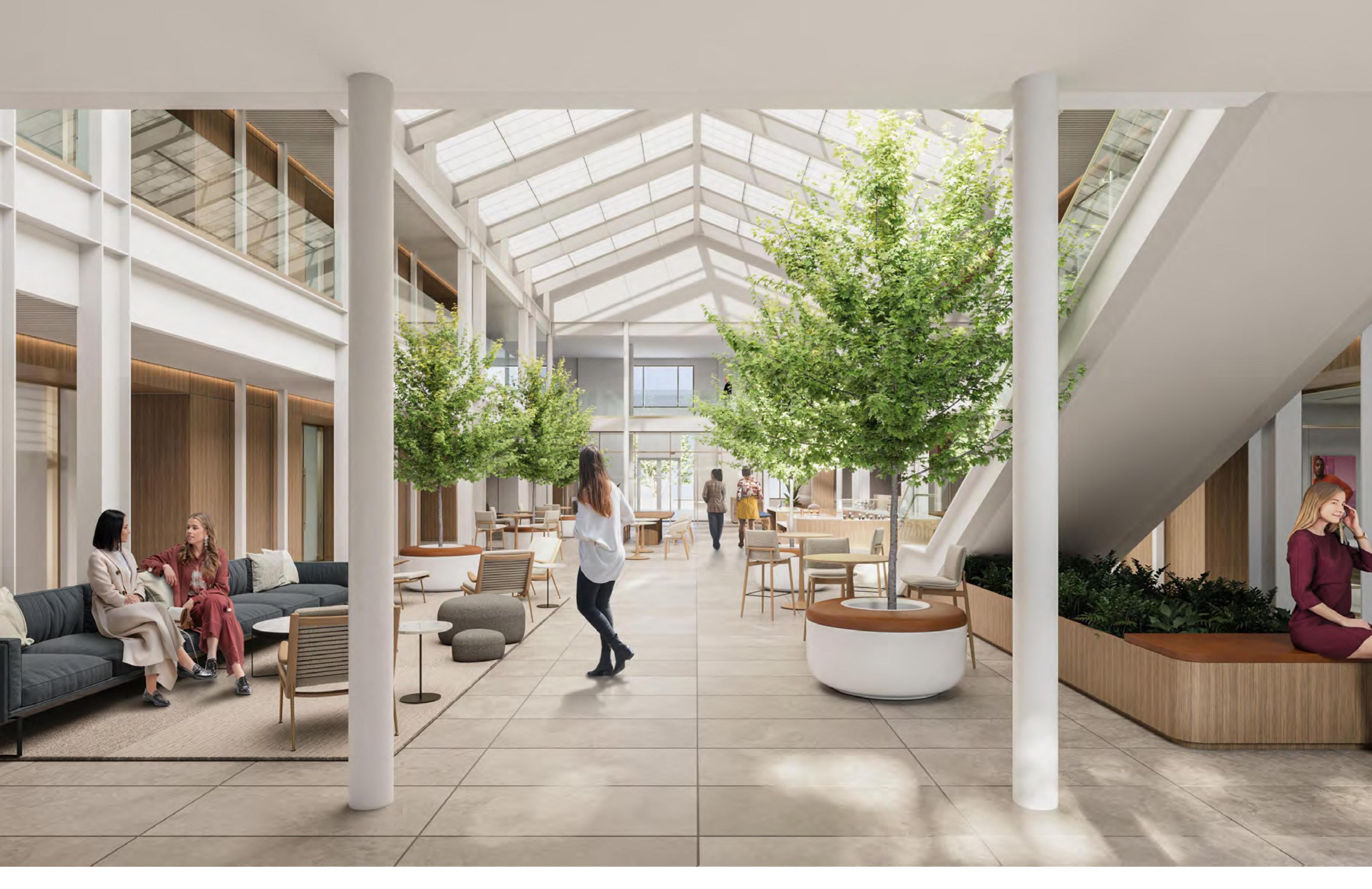
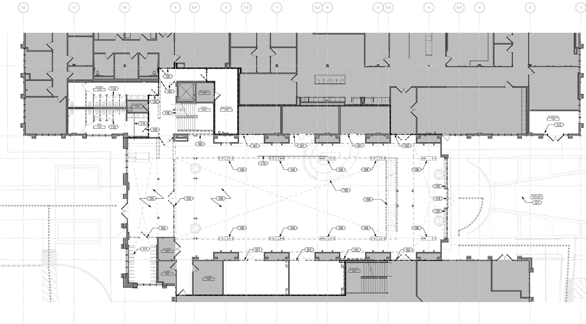
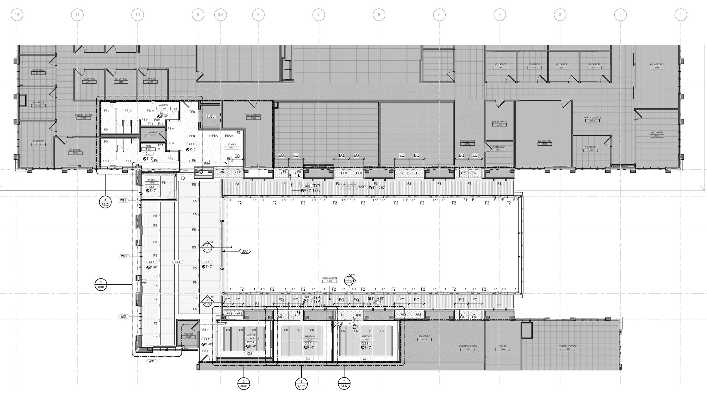
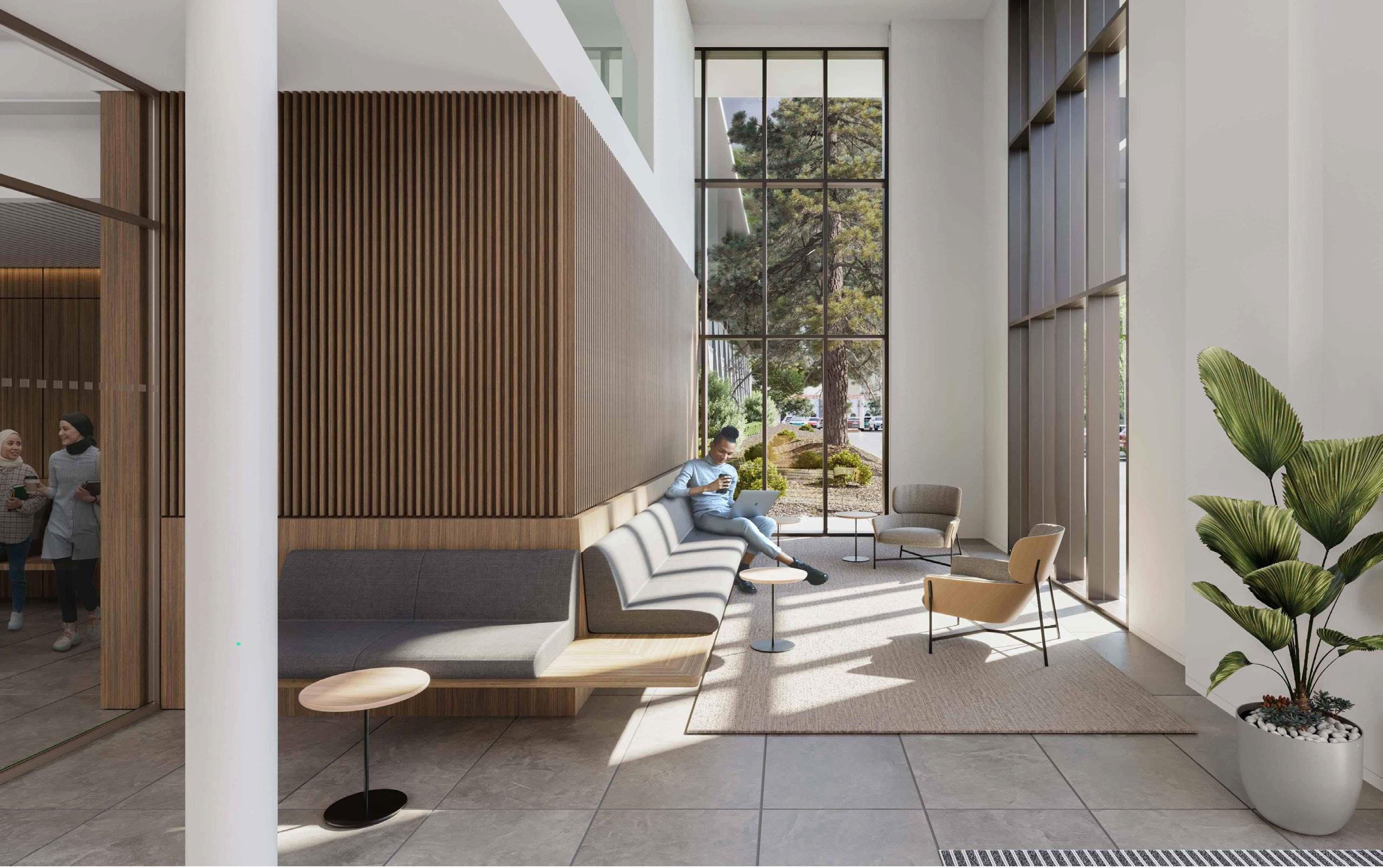
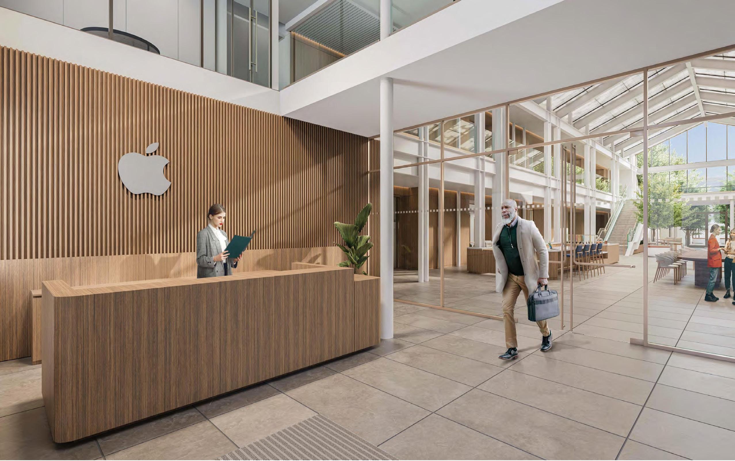
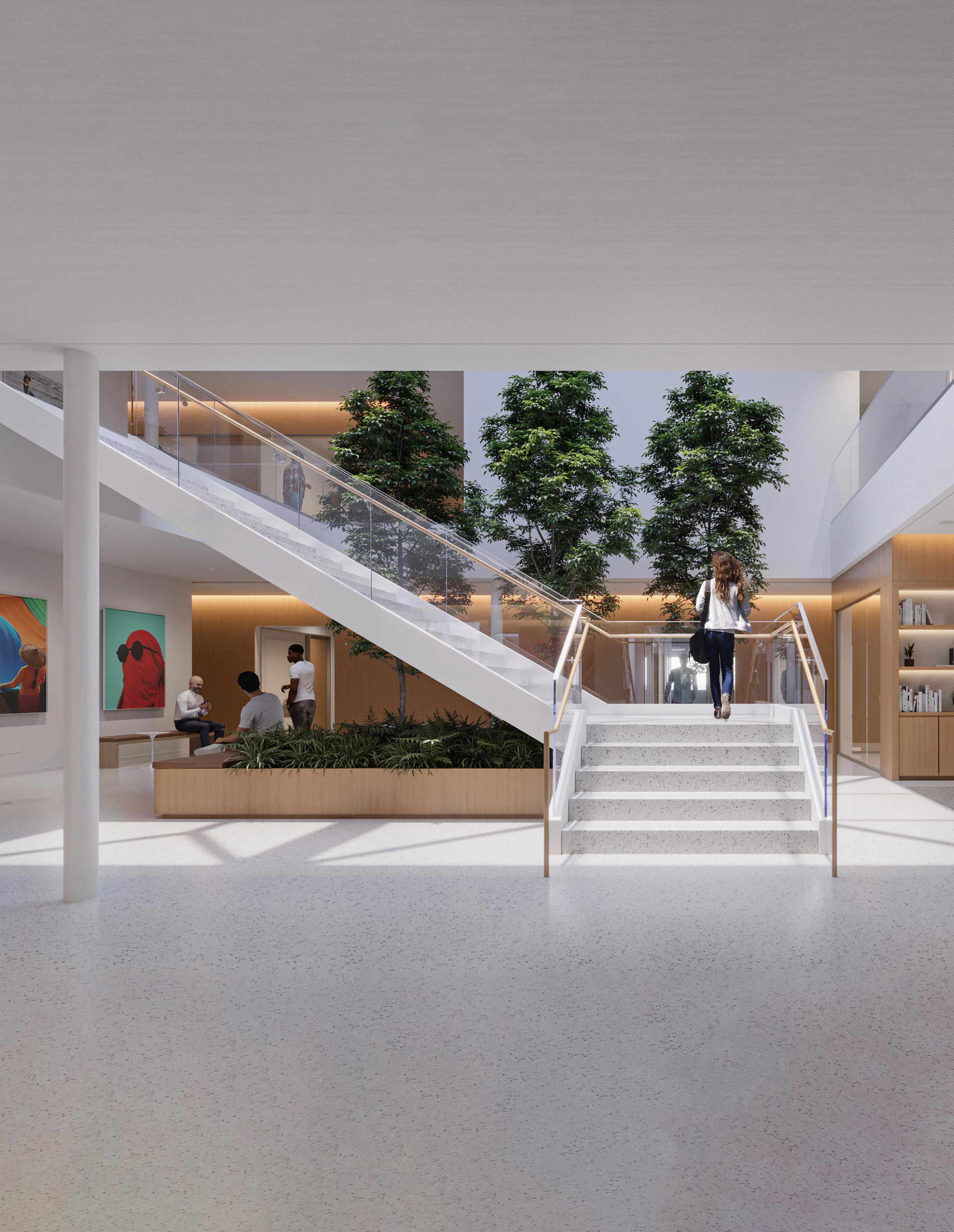
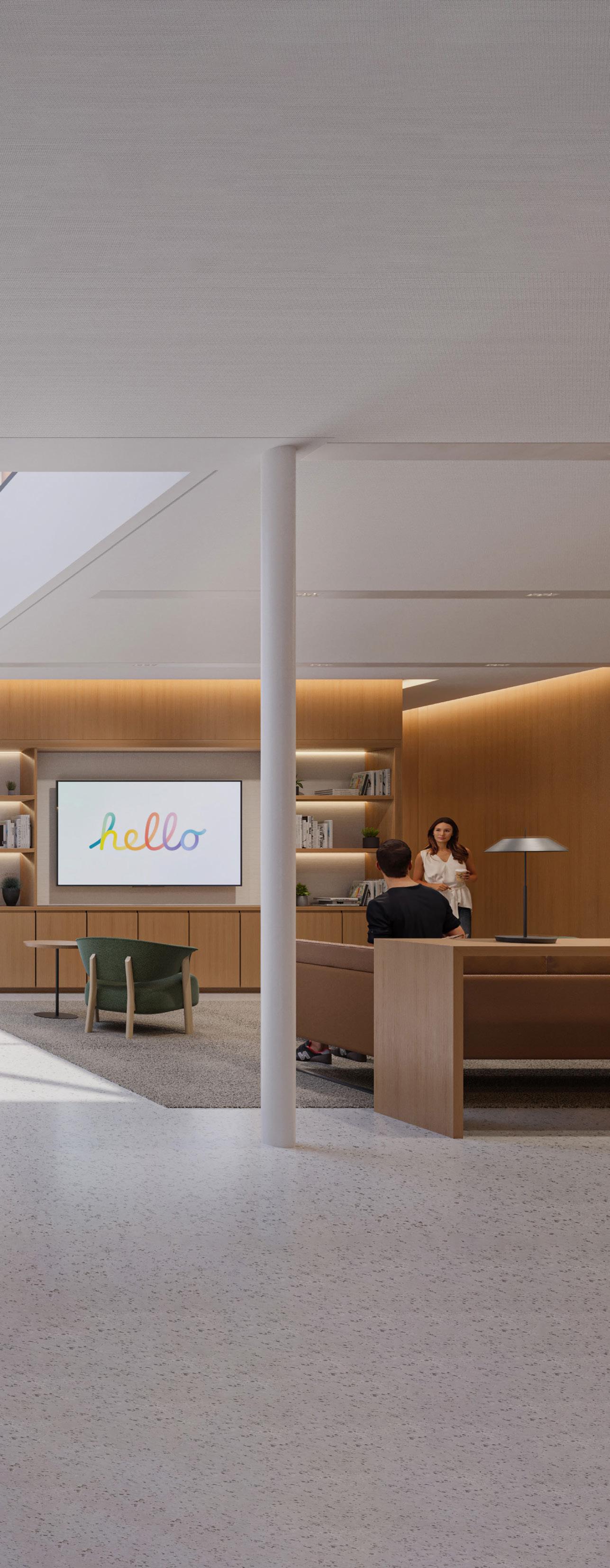
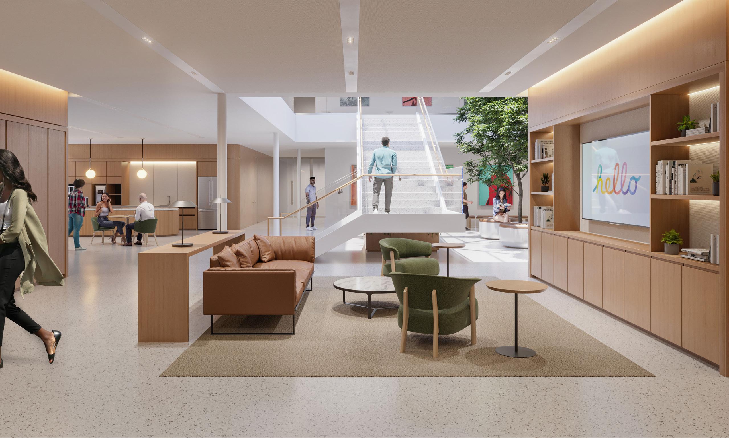
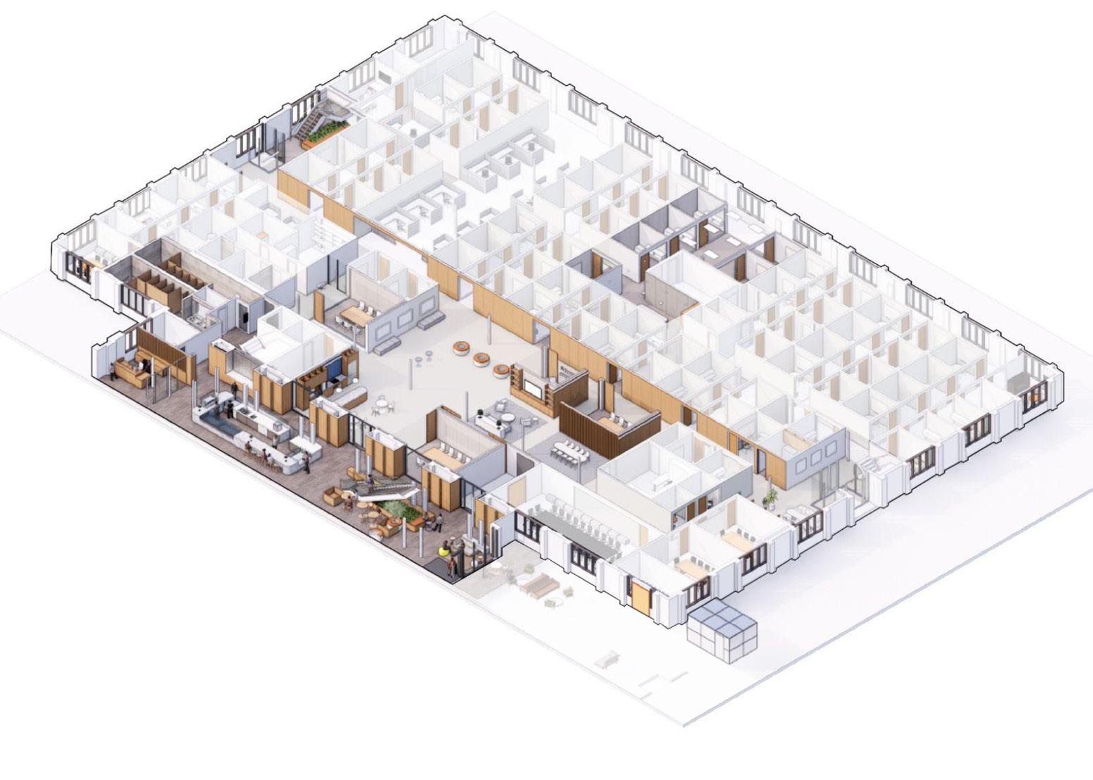
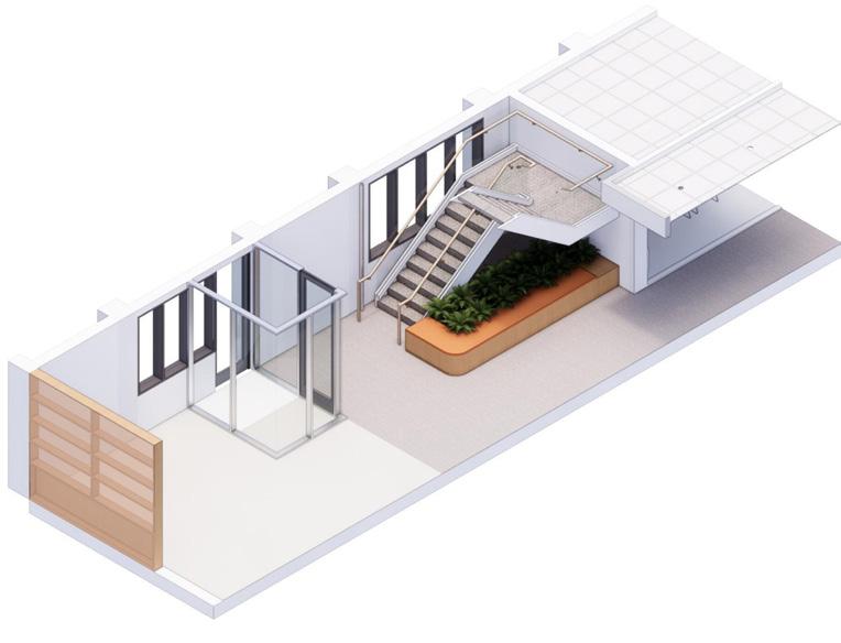
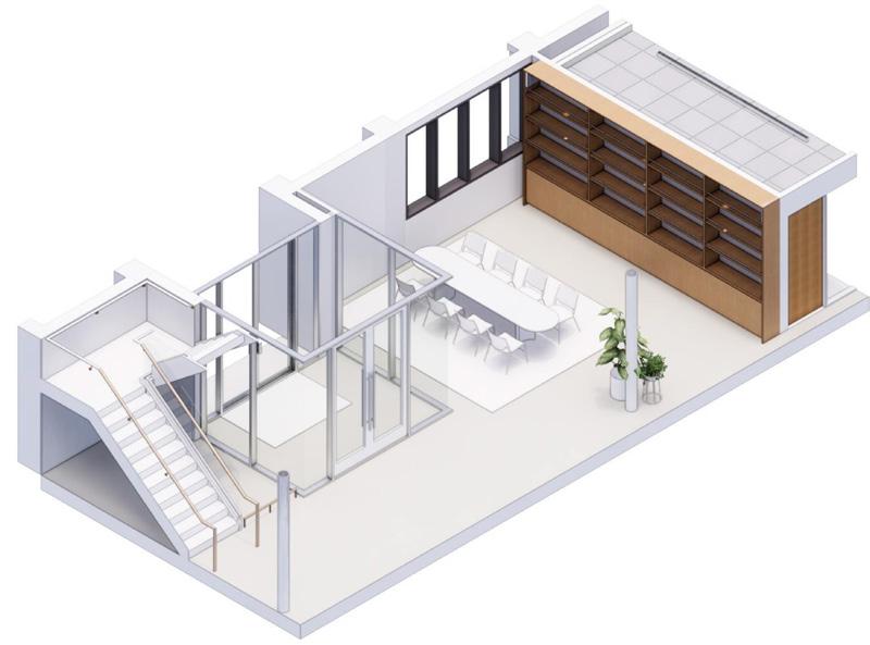
THE ATRIUM
Professional Work: STUDIOS Architecture Supervisor: Kristian Passinita & Jose
This tenant improvement project of an existing two story atrium connects two office spaces of a tech company. The overall look and feel of Atrium respects and celebrates the inside outside concept by bringing in the warm tones and feel of a courtyard inside. The linearity of this Atrium is broken by introducing communal bar and various seating options encouraging informal meetings, dining, and relaxation. The overall design of the Atrium allows for opportunities to bump into friends and foster a sense of community between two very different yet connected world of a tech company.

 Demolition Plan - Level 1
Proposed Plan - Level 1

Proposed RCP - Level 1 Declaimer: All
in this project belong to STUDIOS Architecture
the drawings
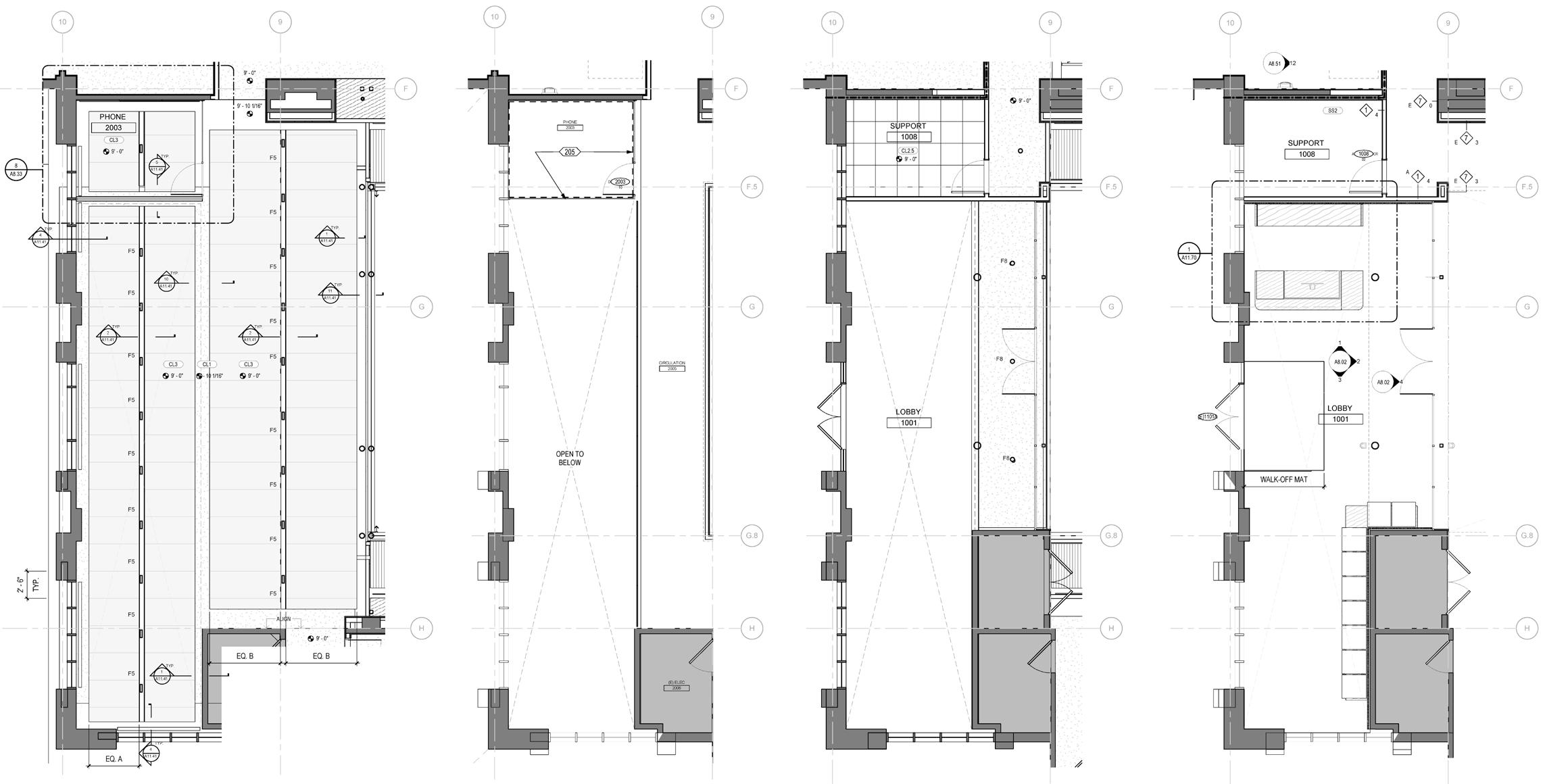
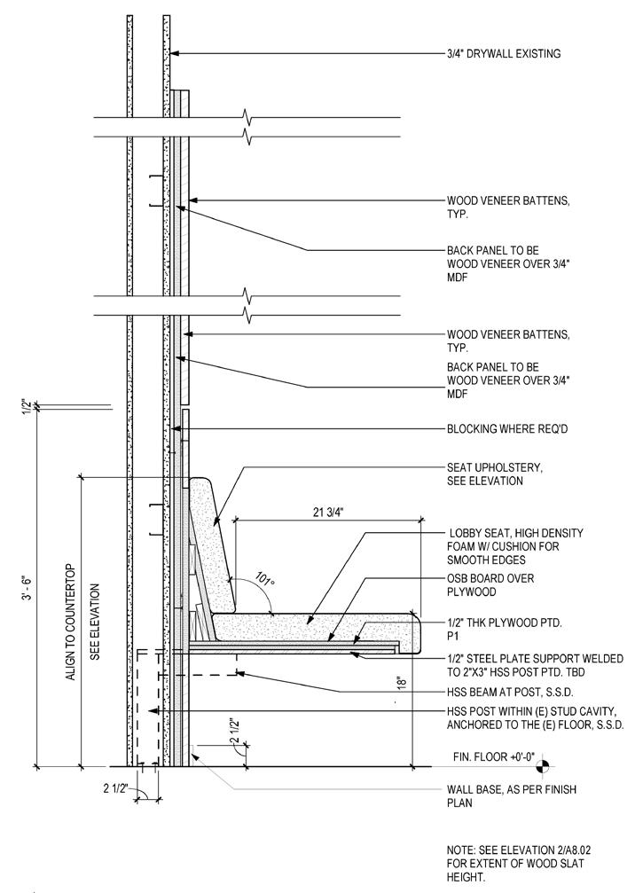
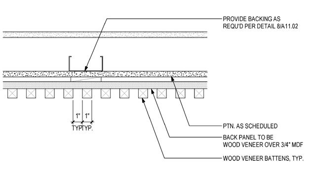
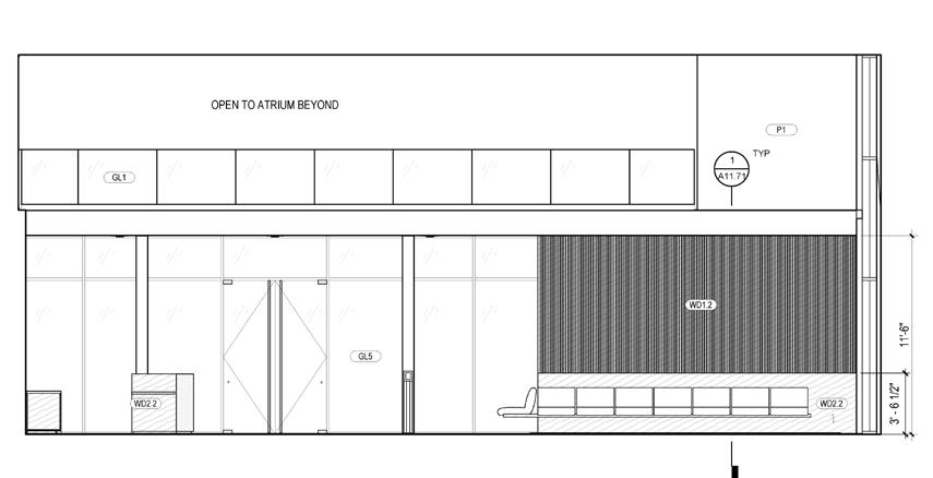
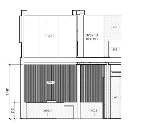
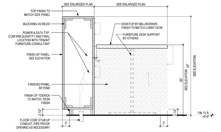
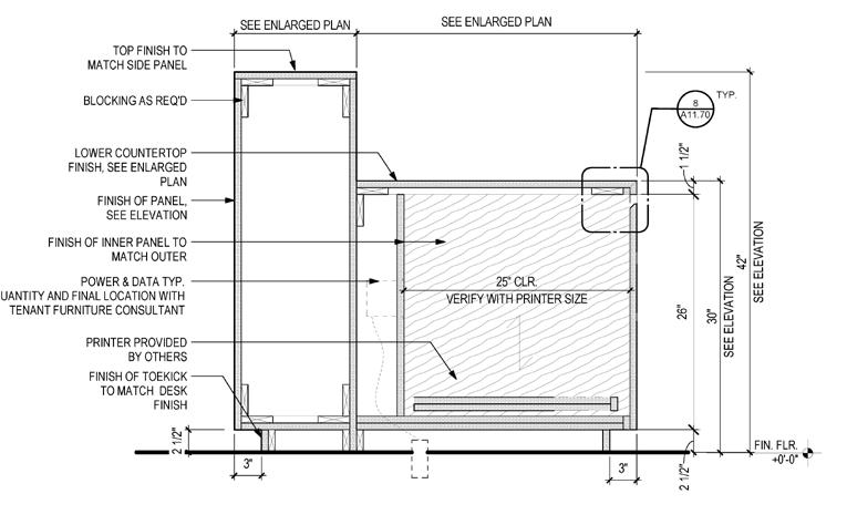
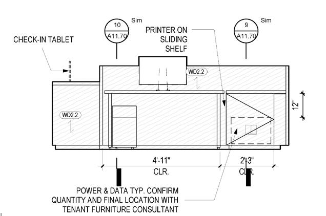
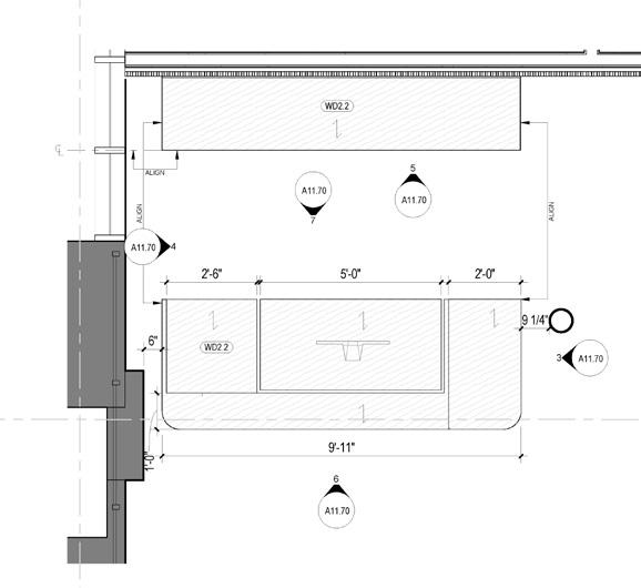
Enlarged Lobby RCPLevel 2 Enlarged Floor Plan - Level 2 Int. Elevation - Lobby - North Enlarged Lobby RCPLevel 1 Enlarged Floor Plan - Level 1 Int. Elevation - Lobby - West Plan Detail at Lobby Feature Wall Plan Detail at Lobby Feature Wall Reception Desk - Back Elevation Enlarged Plan - Reception Desk Section at Reception Desk Station Section at Reception Desk Lower Counter Declaimer: All the drawings in this project belong to STUDIOS Architecture
THE WEST
Professional Work: STUDIOS Architecture
Supervisor: Kristian Passinita & Jose
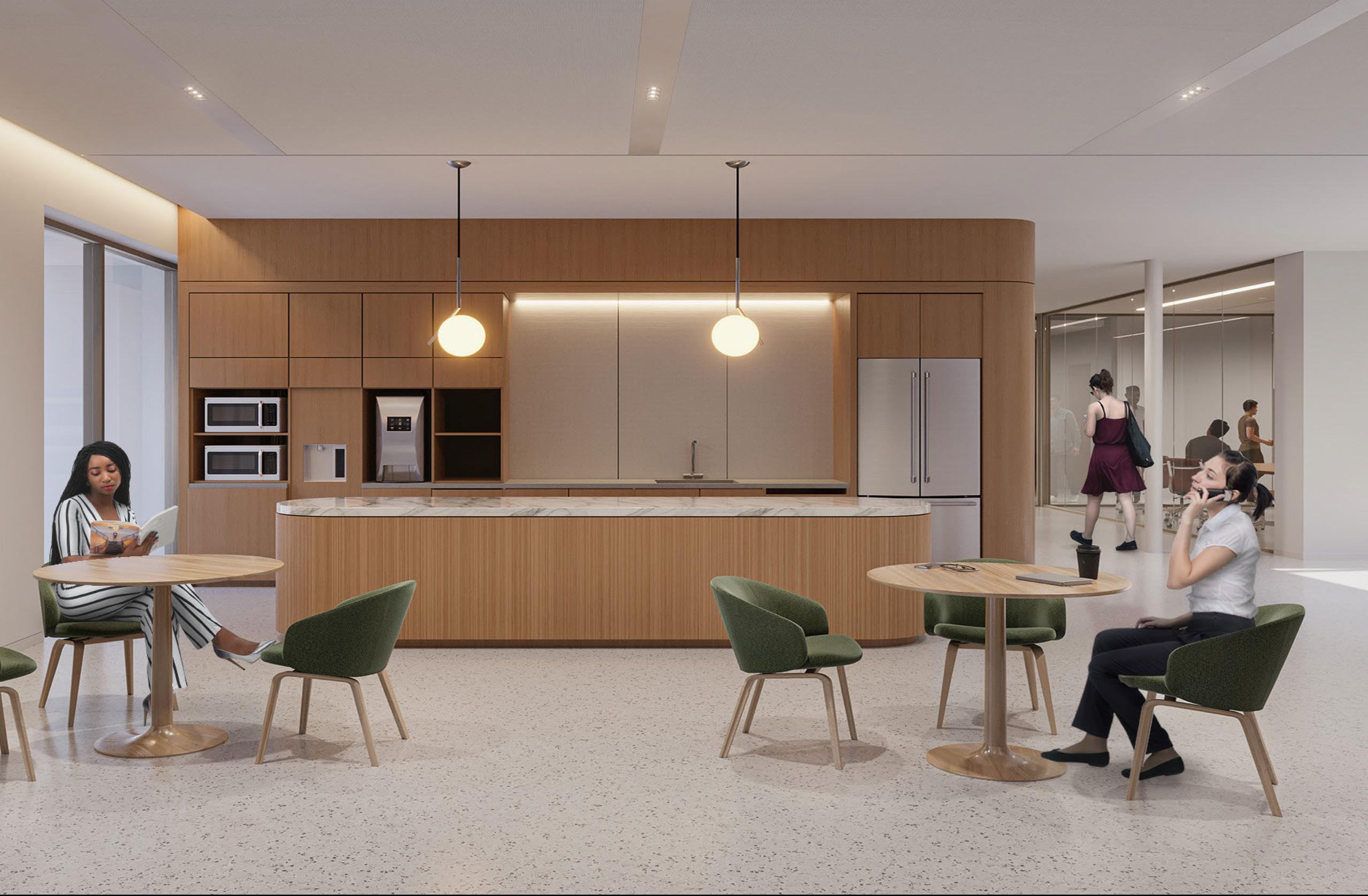
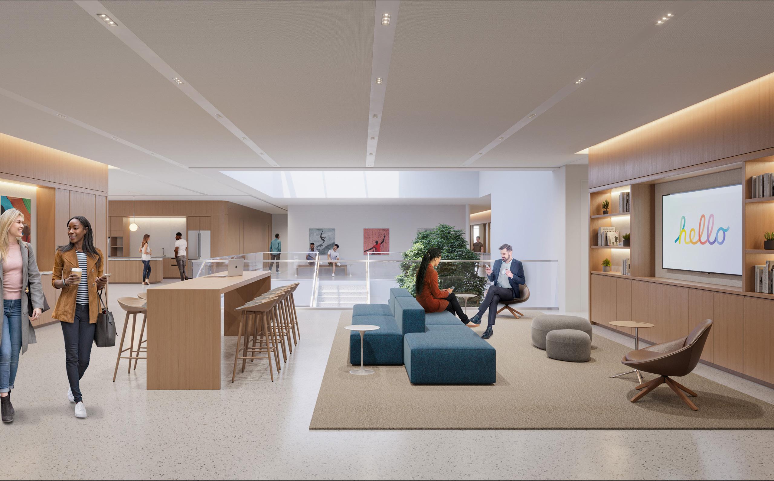
Located in Cupertino, this office serves the Legal team of a tech company. The design brings together the flexibility and collaboration opportunities inherent to tech workplaces with a warm, sophisticated palette suited to this forward-thinking Tech Client. We overhauled an outdated work floor with a timeless and functional design that feeds natural light to the central lounge and assistant bays. We also placed a continuous linear band of light between two parallel fabric panels bringing more light into the space while providing acoustic treatment and gave new life to the existing private office.
 Axon - Level 1
Axon - North Lounge - Level 1
Axon - South Lounge - Level 1
Axon - Level 1
Axon - North Lounge - Level 1
Axon - South Lounge - Level 1
Proposed Plan - Level 1
Demolition Plan - Level 1
Declaimer: All the drawings in this project belong to STUDIOS Architecture
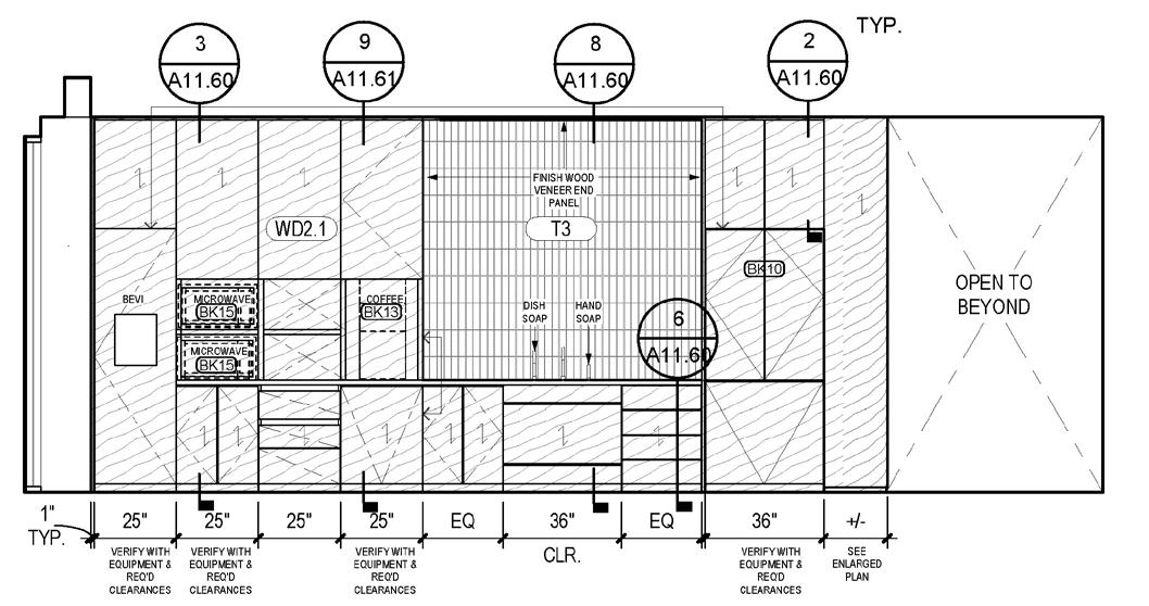
Elevation - Breakroom - Back Counter
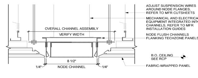
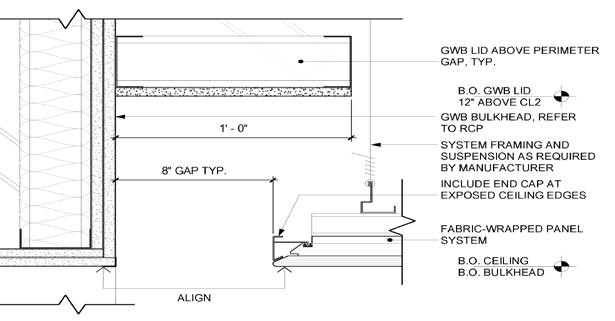
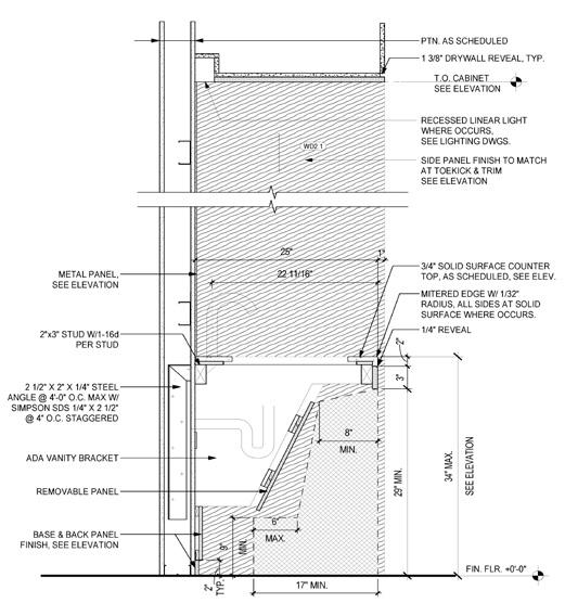
Section at Pantry Sink Detail - Ceiling Edge detail at Recessed Channel and GWB Bulkhead
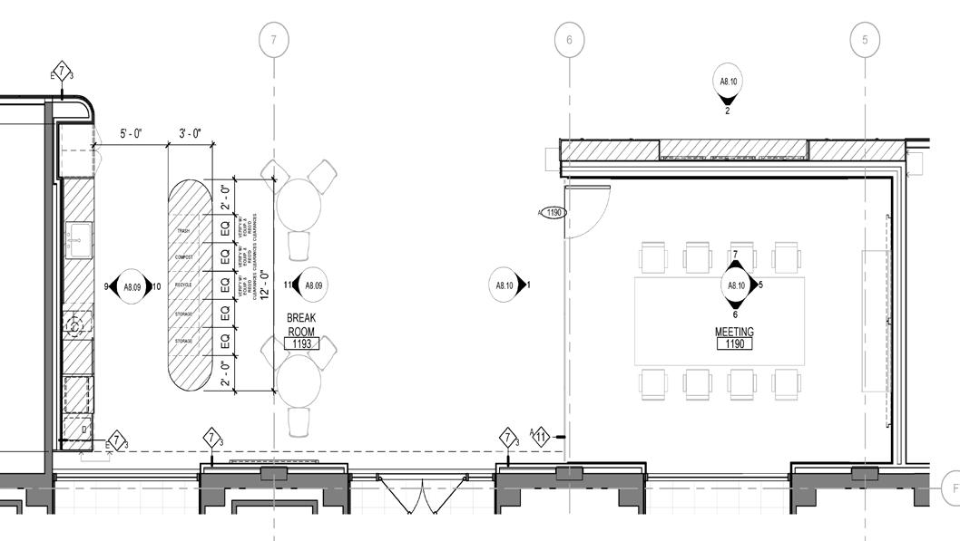
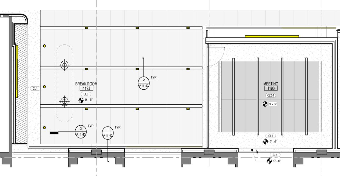
Enlarged Plan - Break Room and Meeting Room
Enlarged Plan - Break Room and Meeting Room
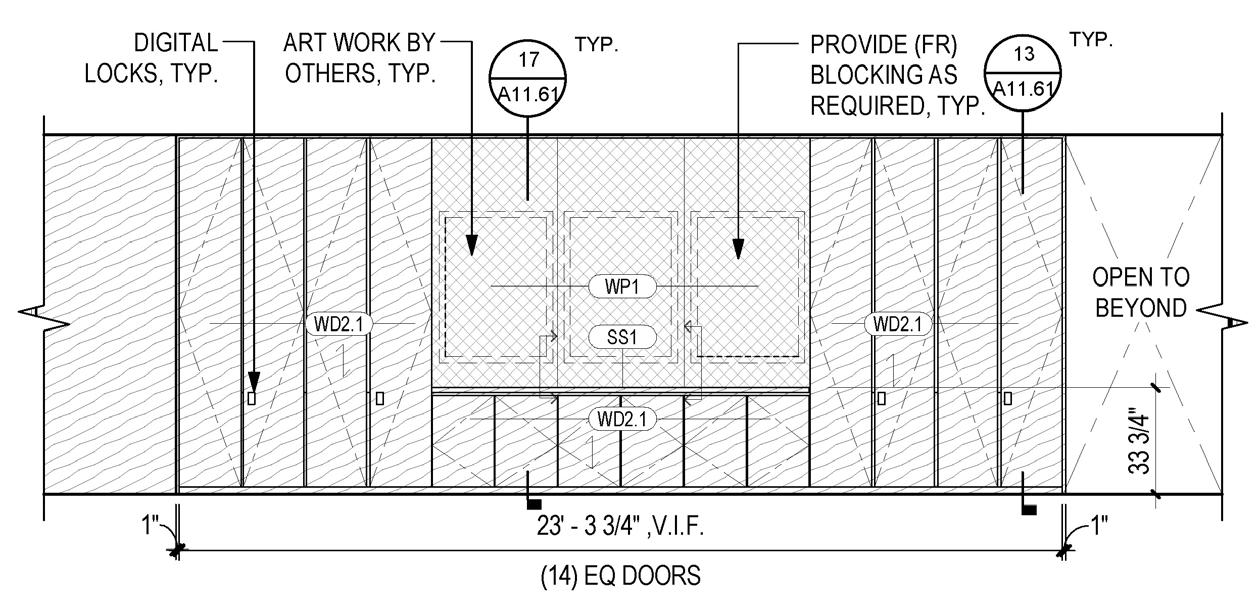
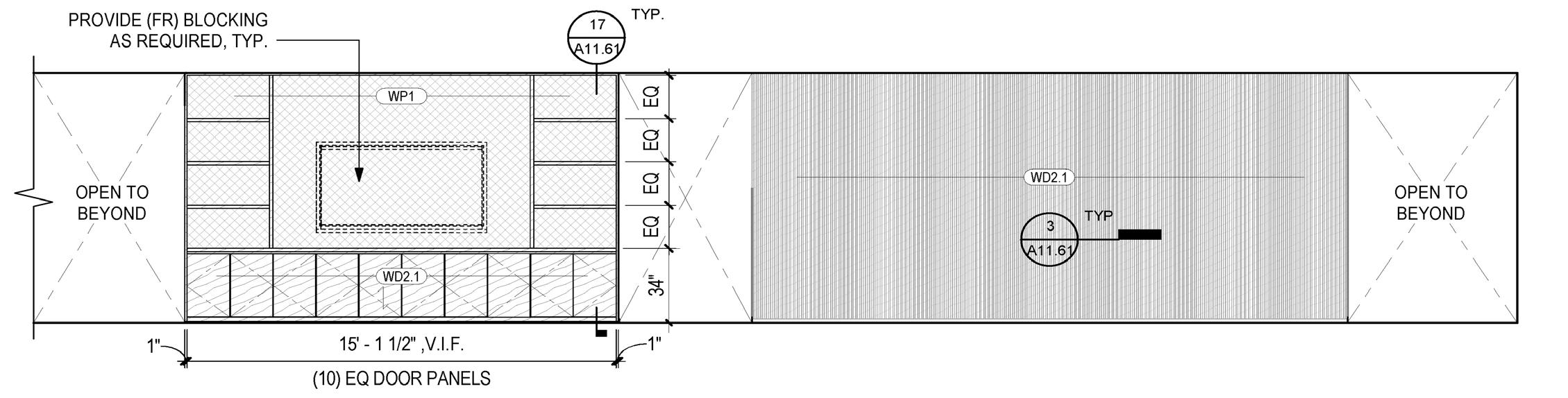
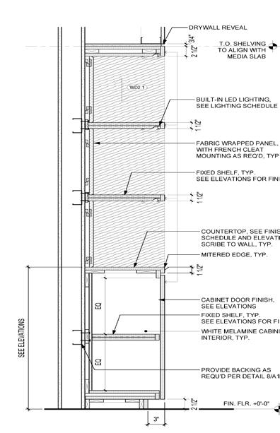
Elevation - Level 1 - Lounge & Tech Concierge East
Elevation - Level 1 - Hallway Millwork
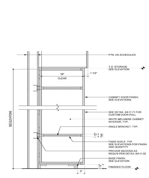
Section at Lounge Shelving and Full Storage Cabinet
Declaimer: All the drawings in this project belong to STUDIOS Architecture
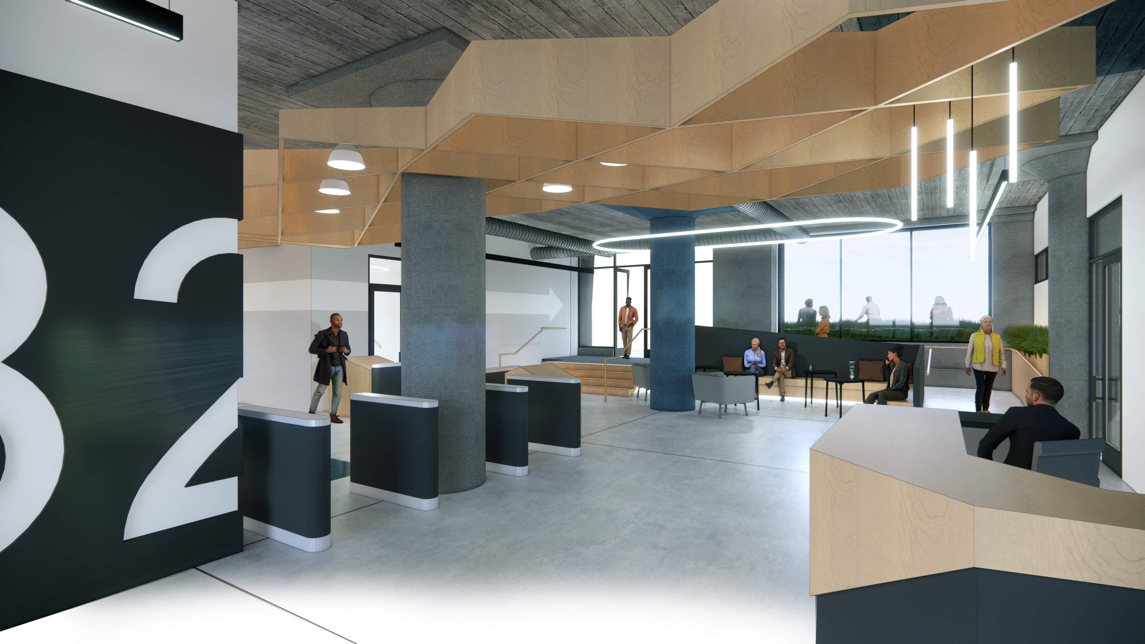
THE WAREHOUSE
Professional Work: TEF Design Supervisor: Justin Blinn & Ivana Pilipovic
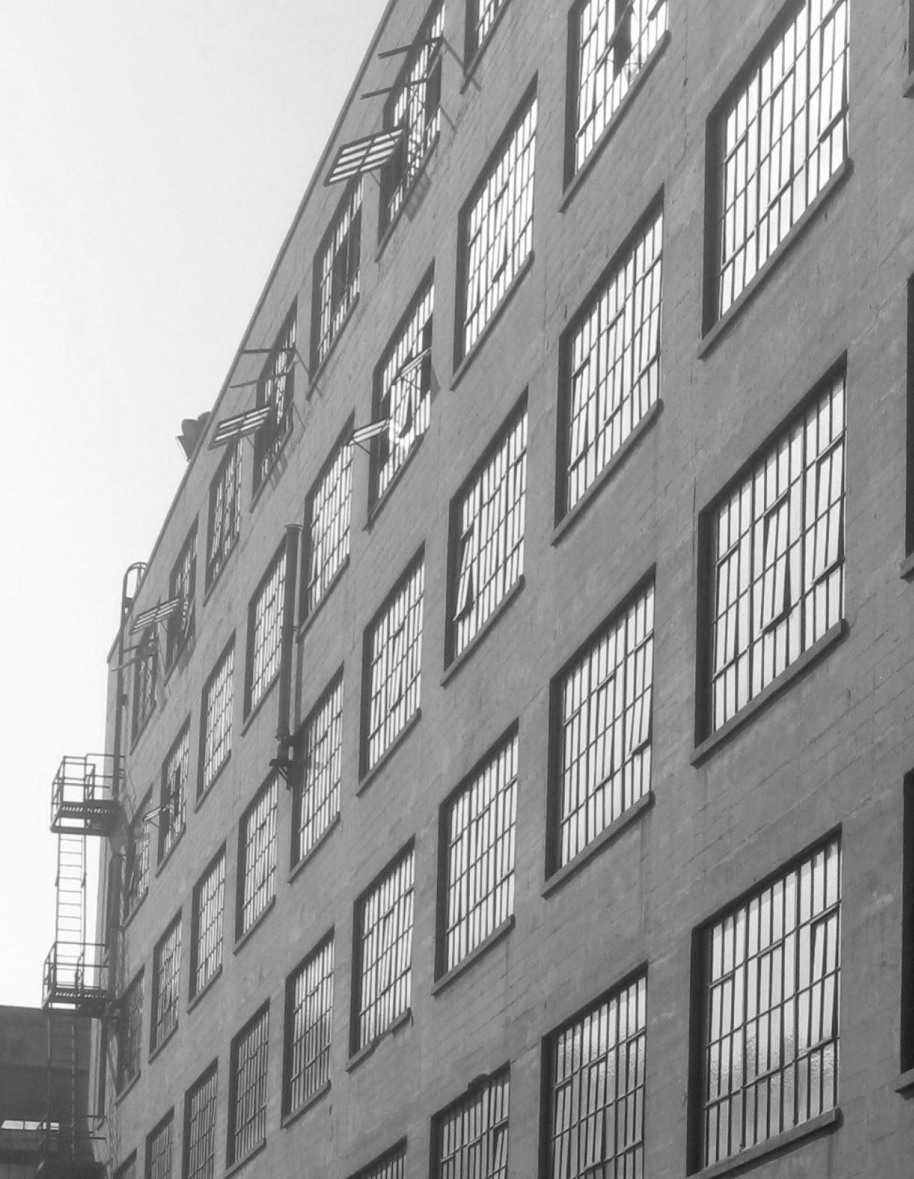
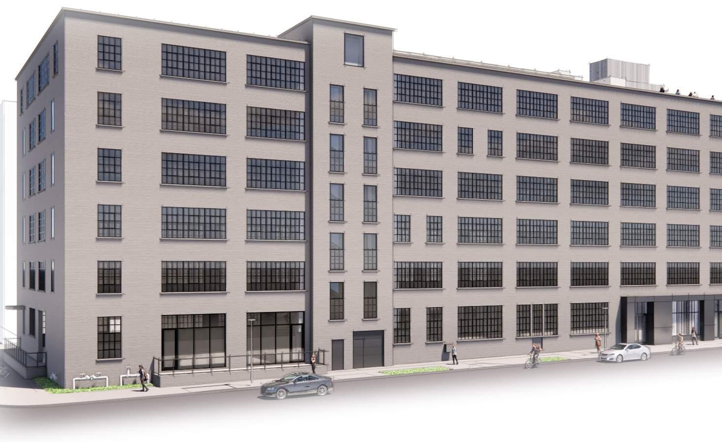
Originally constructed in 1941 as a warehouse for WWII efforts, Building 2 is a simple rectangular concrete structure with large multi-lite windows at each facade. The building is oriented in the north-south direction with loading access at the north, west, and east facades. A sixth floor addition was built in 1944 as a drafting studio. The project entails base building rehabilitation, including envelope improvements and structural retrofit, and adaptive reuse for commercial office use. Building systems, including HVAC, electrical, plumbing, and fire protection, will be all new. The project also includes new vertical circulation elements complying with modern egress requirements, including new elevators and egress stairs.
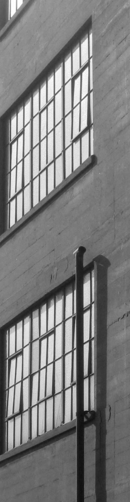
vertically enlarged openings that also provide interior stairwell
opening infill window to be multi-lite, while new window area to be detailed to contrast
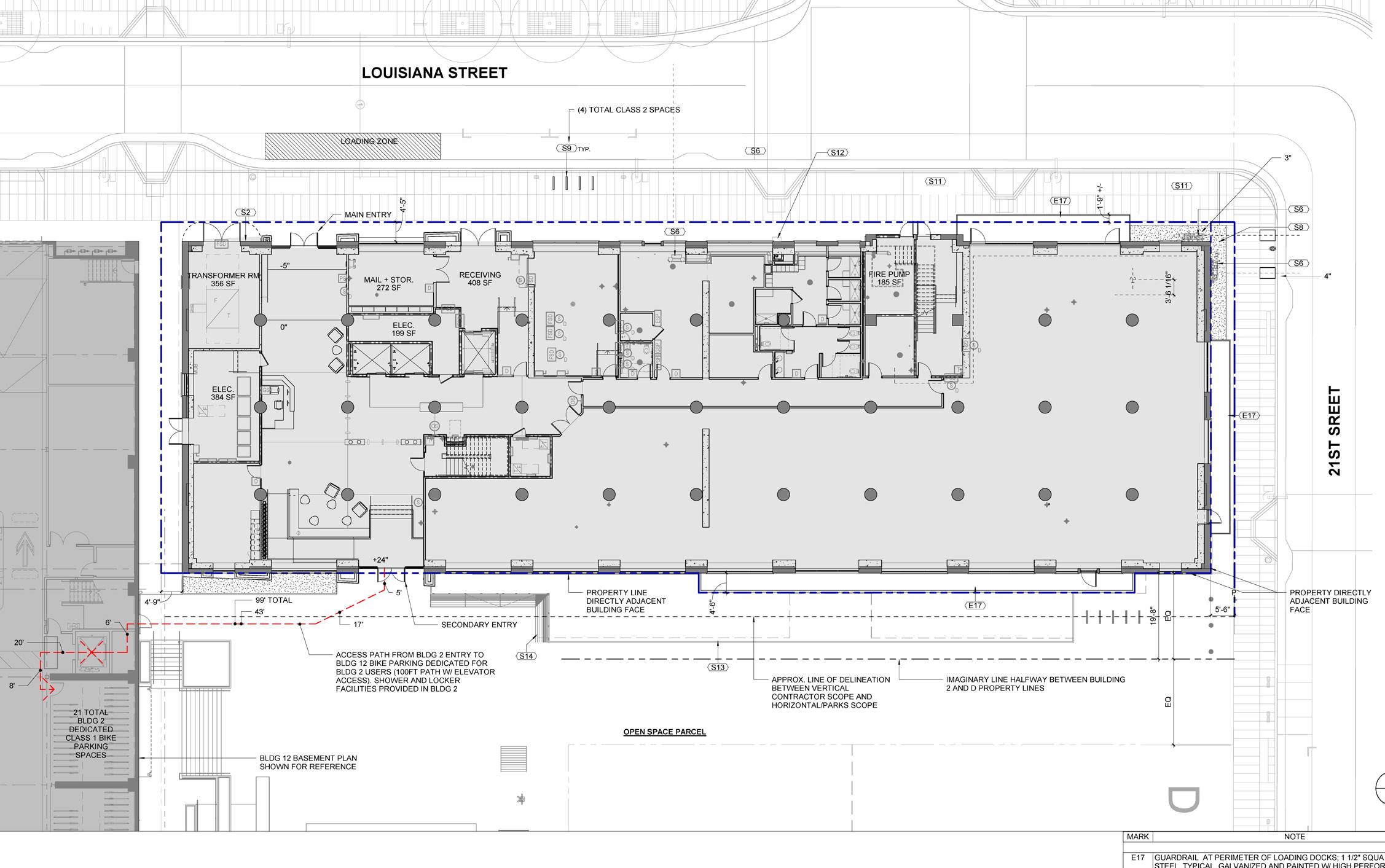
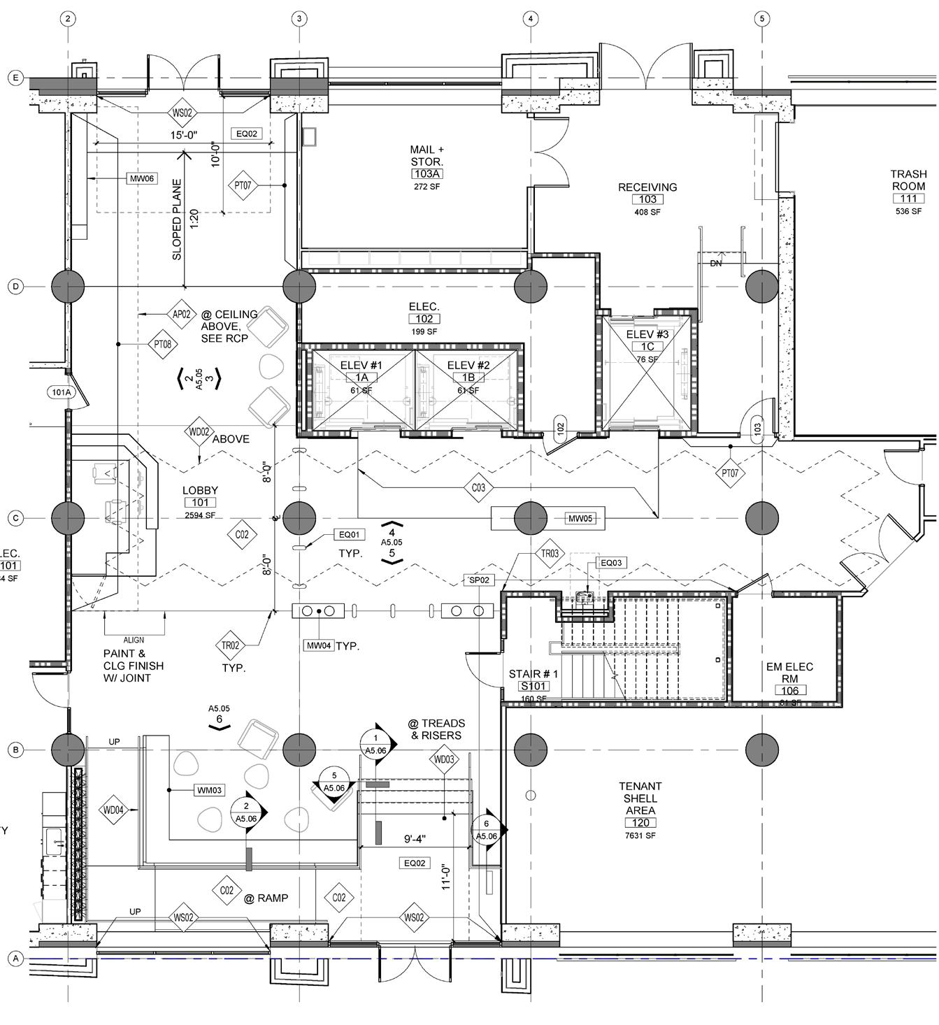
First Floor Plan
BUILDING OVERVIEW |
15 LEVEL 1 0' -0" LEVEL 2 14' -0" LEVEL 3 26' -0" (E) PARAPET 77' -6" LEVEL 4 38' -0" LEVEL 5 50' -0" ROOF (AVG) 75' -1 5/64" 1 2 3 4 5 6 7 LEVEL 6 (NEW) 61' -8" T.O. ROOF SLAB 73' -4" 2 A3.12 E08 E04 E04 F03 S2 E101.1B E101.1A E102 E106 WEST FACADE | INTERVENTIONS
12.07.2020 |
0' -0" 14' -0" PARAPET 77' -6" LEVEL 5 -1 5 T.O. ROOF SLAB 73' 2 A3.12 E08 E04 E04 S2 E101.1B E102 E106 LEVEL 1 0' -0" LEVEL 2 14' -0" LEVEL 3 26' -0" (E) PARAPET 77' -6" LEVEL 4 38' -0" LEVEL 5 50' -0" ROOF (AVG) 75' -1 5/64" 1 2 3 4 5 6 7 LEVEL 6 (NEW) 61' -8" T.O. ROOF SLAB 73' -4" 2 A3.12 E08 E04 E04 F03 S2 E101.1B E101.1A E102 E106 LEVEL 1 0' -0" (E) PARAPET 77' -6" LEVEL 5 50' -0" ROOF (AVG) 75' -1 5/64" 1 2 3 4 5 6 7 LEVEL 6 (NEW) 61' -8" T.O. ROOF SLAB 73' -4" 2 A3.12 E08 E04 E04 F03 S2 E101.1B E101.1A E102 E106 LEVEL 1 0' -0" (E) PARAPET 77' -6" LEVEL 4 LEVEL 5 50' -0" ROOF (AVG) 75' -1 5/64" 1 2 3 4 5 6 7 LEVEL 6 (NEW) 61' -8" T.O. ROOF SLAB 73' -4" 2 A3.12 E08 E04 E04 F03 S2 E101.1B E101.1A E106 LEVEL 1 0' -0" LEVEL 2 LEVEL 3 26' -0" (E) PARAPET 77' -6" LEVEL 4 38' -0" LEVEL 5 50' -0" ROOF (AVG) 75' -1 5/64" LEVEL 6 (NEW) 61' -8" T.O. ROOF SLAB 73' -4" E08 E04 E04 F03 S2 E101.1B E101.1A E102 E106 LEVEL 1 0' -0" LEVEL 2 LEVEL 3 26' -0" (E) PARAPET 77' -6" LEVEL 4 38' -0" LEVEL 5 50' -0" ROOF (AVG) 75' -1 5/64" LEVEL 6 (NEW) 61' -8" T.O. ROOF SLAB 73' -4" E08 E04 E04 F03 S2 E101.1B E101.1A E106 LEVEL 1 0' -0" (E) PARAPET 77' -6" 50' -0" ROOF (AVG) 75' -1 5/64" 1 2 3 4 5 6 7 LEVEL 6 (NEW) 61' -8" T.O. ROOF SLAB 73' -4" 2 A3.12 E08 E04 E04 F03 S2 E101.1B E101.1A E102 E106 LEVEL 1 0' -0" (E) PARAPET 77' -6" 50' -0" ROOF (AVG) 75' -1 5/64" 1 2 3 4 5 6 7 LEVEL 6 (NEW) 61' -8" T.O. ROOF SLAB 73' -4" 2 A3.12 E08 E04 E04 F03 S2 E101.1B E101.1A E106 LEVEL 1 0' -0" LEVEL 2 (E) PARAPET 77' -6" ROOF (AVG) 75' -1 5/64" 1 2 3 4 5 6 7 LEVEL 6 (NEW) 61' -8" T.O. ROOF SLAB 73' -4" 2 A3.12 E08 E04 E04 F03 S2 E101.1B E101.1A E102 E106 LEVEL 1 0' -0" LEVEL 2 (E) PARAPET 77' -6" ROOF (AVG) 75' -1 5/64" 1 2 3 4 5 6 7 LEVEL 6 (NEW) 61' -8" T.O. ROOF SLAB 73' -4" 2 A3.12 E08 E04 E04 F03 S2 E101.1B E101.1A E106
Proposed West Entry Elevation & Plan
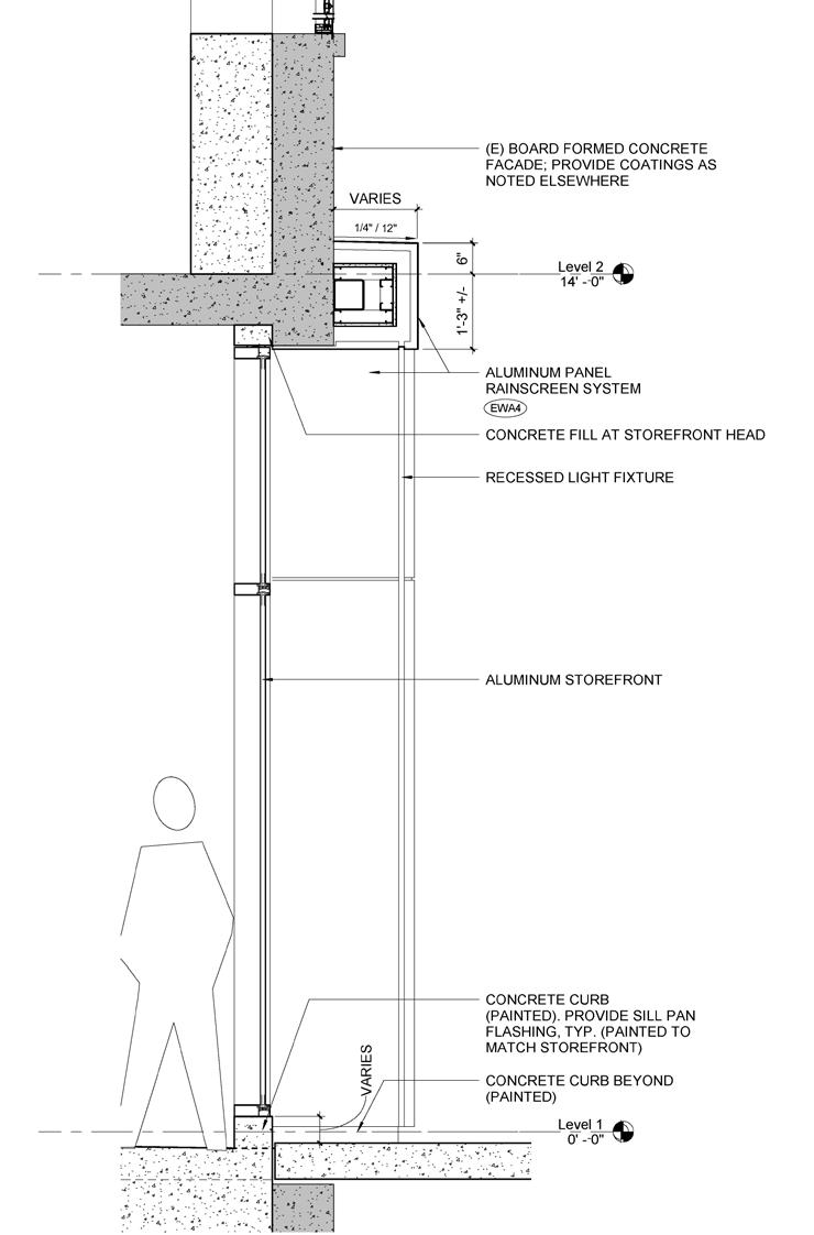
Proposed Section of Entry Storefront
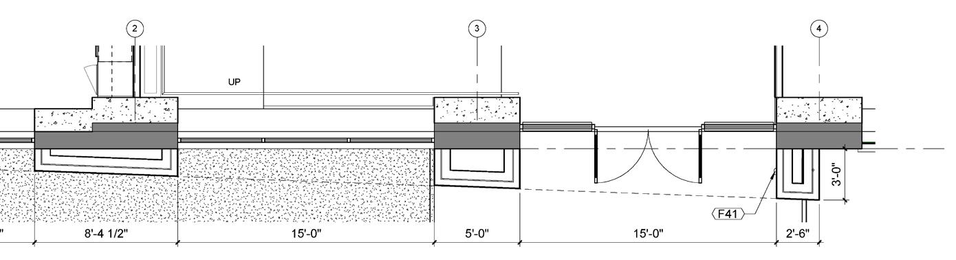
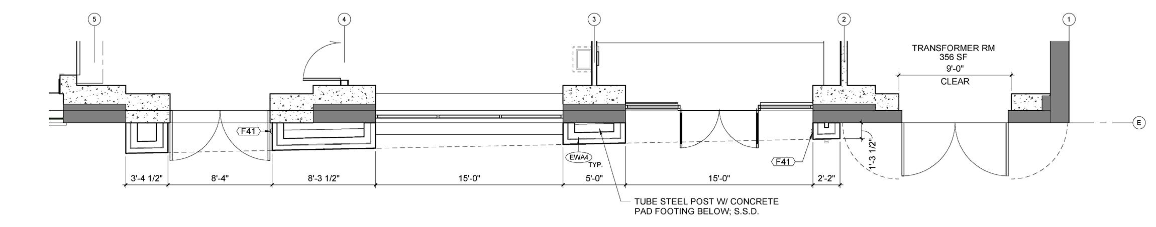

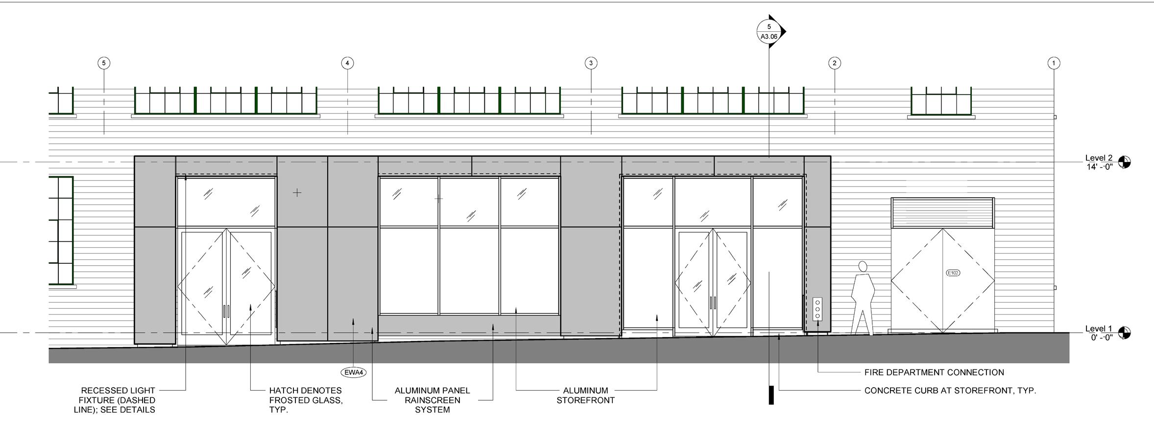
Proposed East Entry Elevation & Plan
Declaimer: All the drawings in this project belong to
TEF Design
Office Design | 07.021.2020 | CRAFT | PERSPECTIVE Office Design | 07.021.2020 | 8 CRAFT | NORTH ELEVATION
View
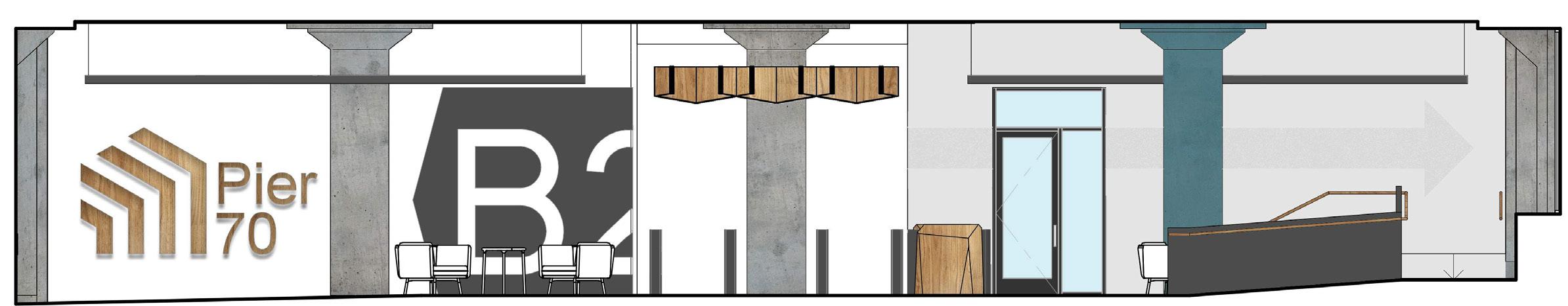
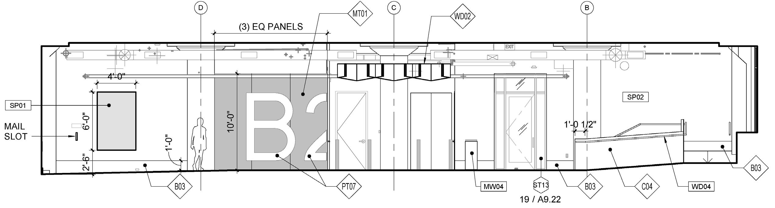
Lobby
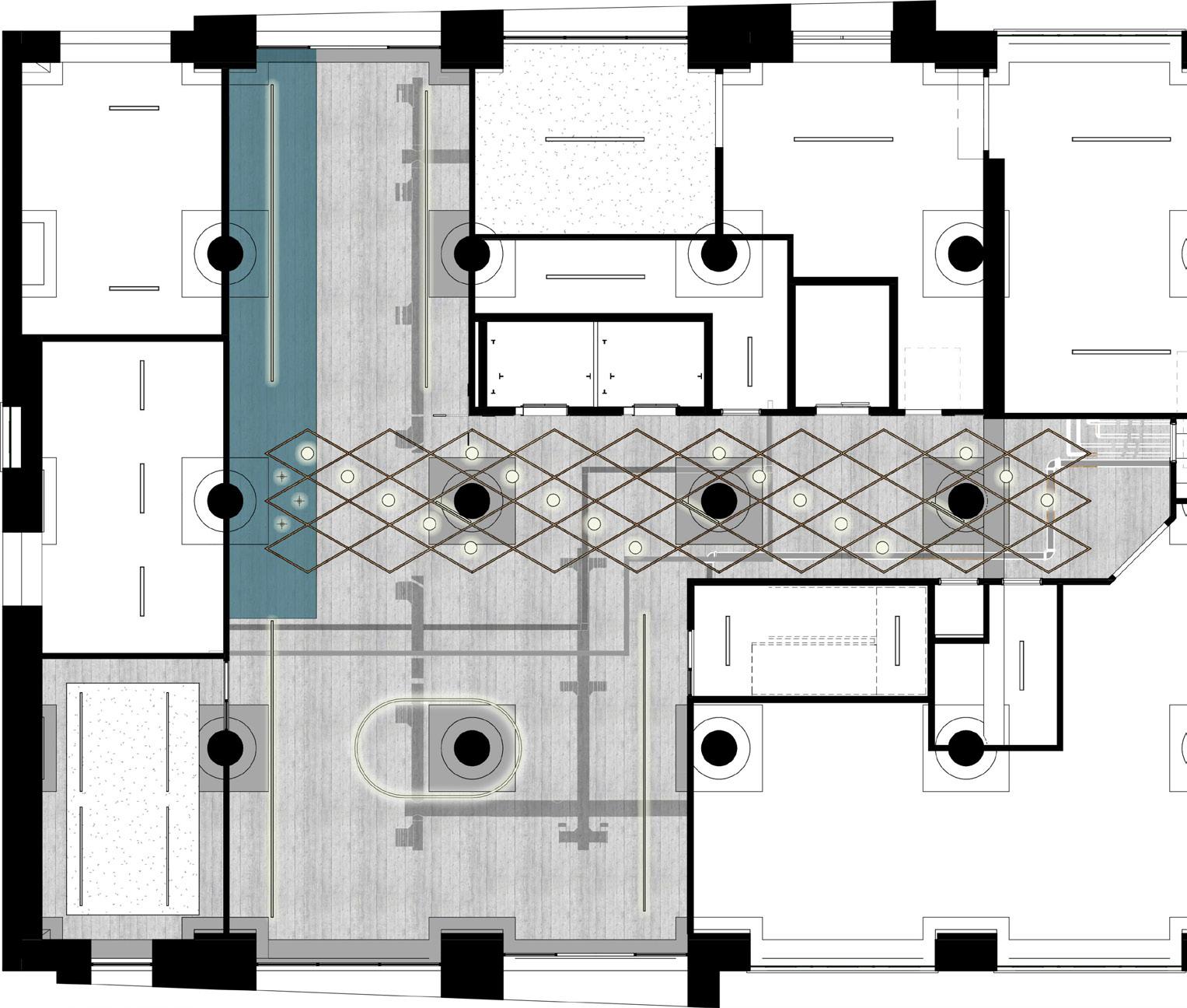
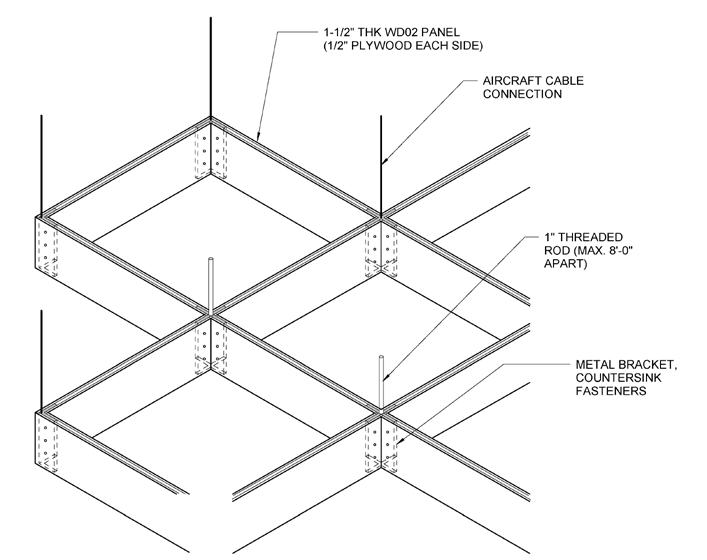
Office Design | 07.021.2020 | 4 CRAFT | REFLECTED CEILING PLAN WOOD BENCH W/ COLUMN MOUNTED BRACKET MW05 1" THREADED ROD (MAX. 8'-0" APART) AIRCRAFT CABLE CONNECTION 1-1/2" THK WD02 PANEL (1/2" PLYWOOD EACH SIDE) METAL BRACKET, COUNTERSINK FASTENERS All drawings and written material appearing herein constitute original and unpublished the Architect and may not be duplicated, used or disclosed without consent of 11 LOBBY DESK -AXO 3/4" = 1'-0" 9 LOBBY DIAGRID JOINT & SUPPORTS Enlarged Lobby Floor Plan Details Enlarged Lobby RCP Plan
Diagrid Joint & Supports
Desk - Axo Declaimer: All the drawings in this project belong to TEF Design
Lobby
Lobby
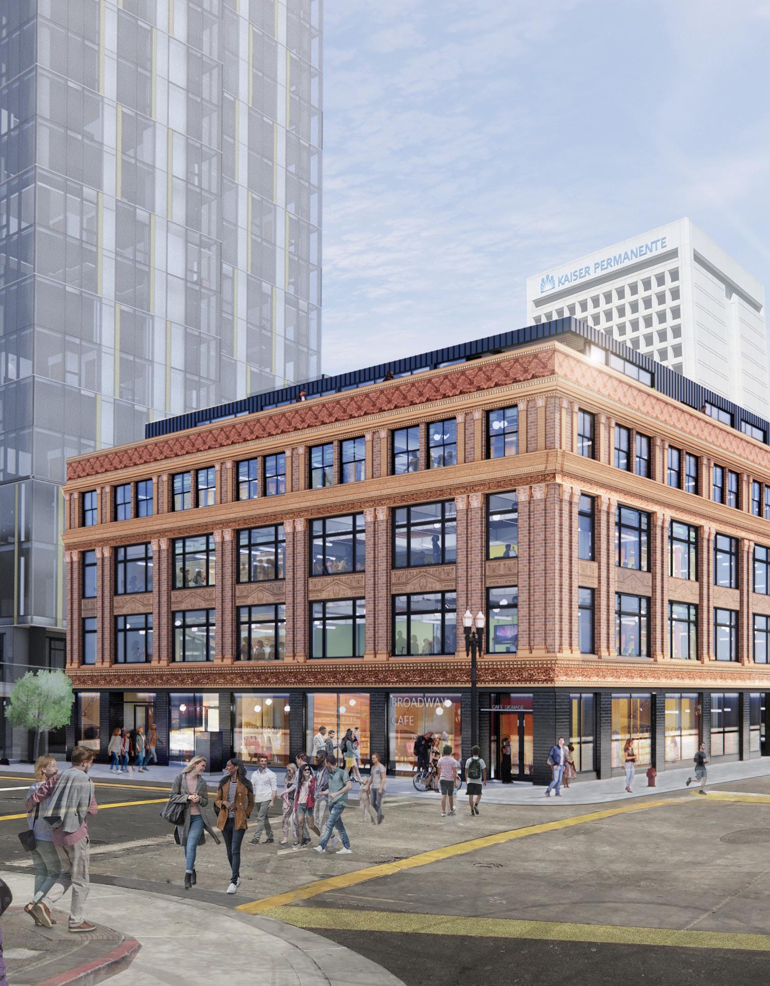
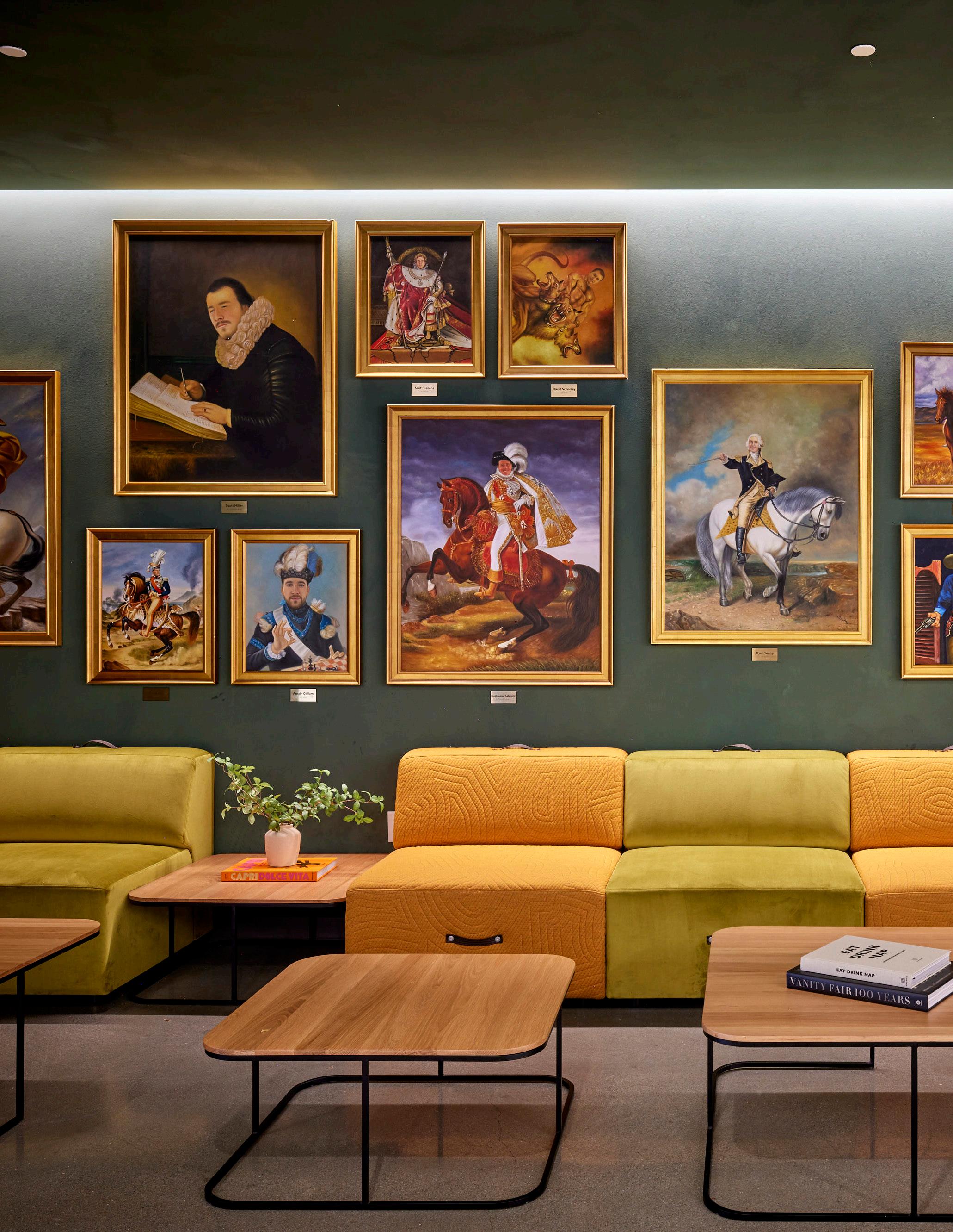
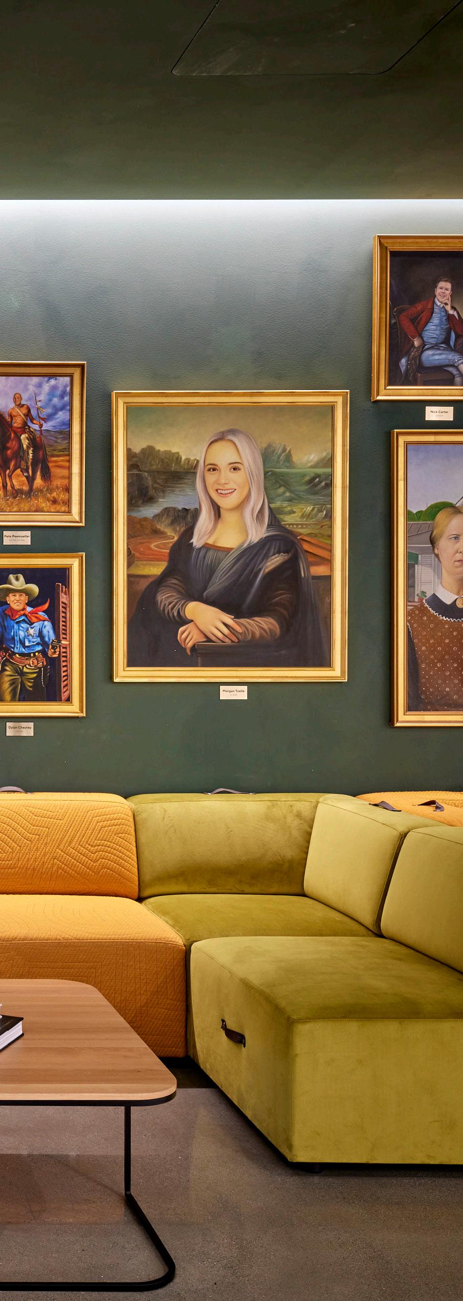
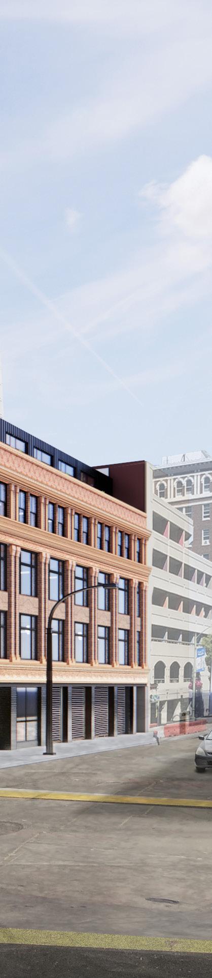
TAPSCOTT
Prefessional Work: TEF Supervisor: Viral Vithalani and Paul Loeffler
The Tapscott Building is a 4-story brick building at the northeast corner of Broadway and 19th. It was built for L. M. Tapscott in the 1920s at 1916 Broadway. The Project entails redeveloping of the facade inorder to bring back the history which the building holds with it and designing the lobby and all the floors for new tenants.
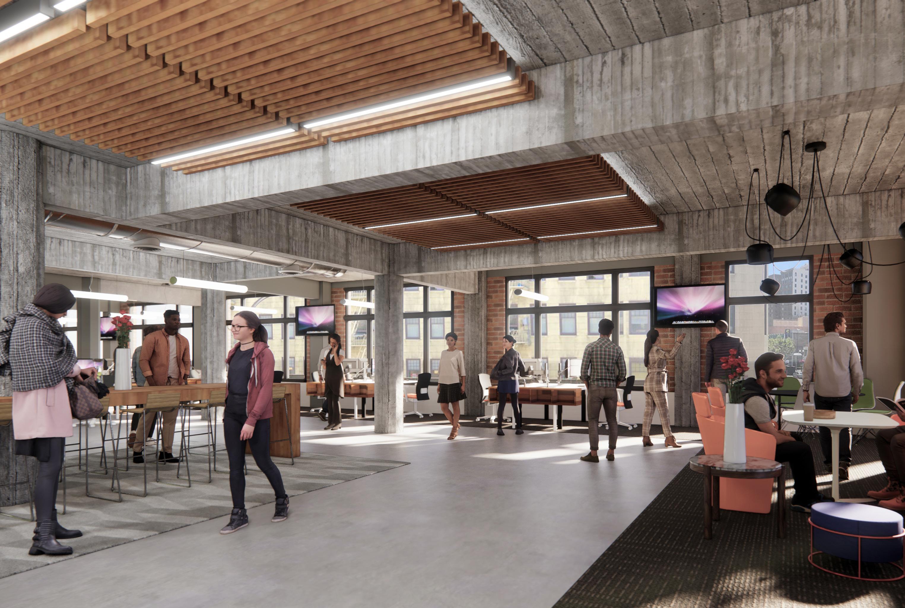
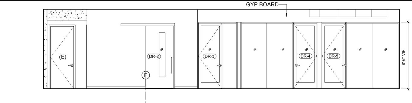
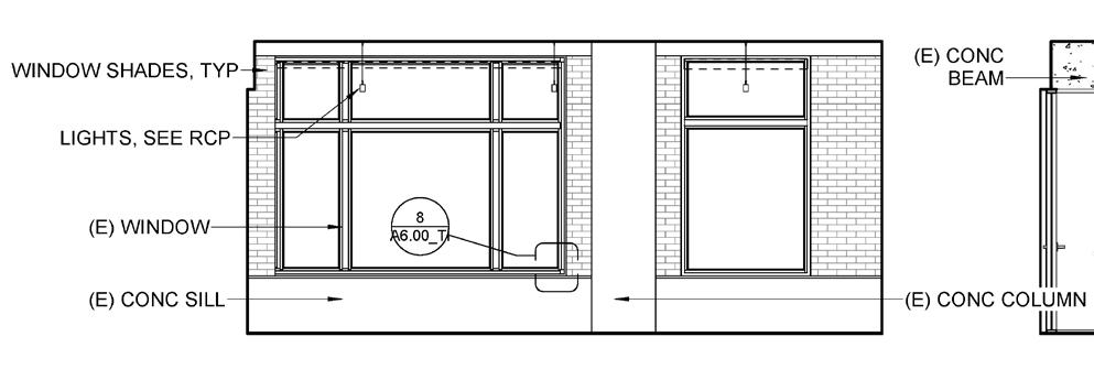
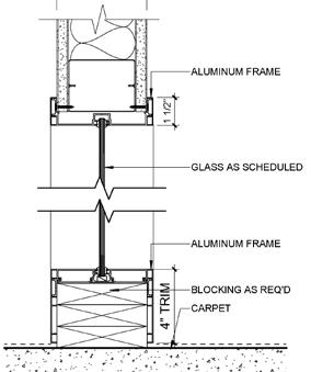
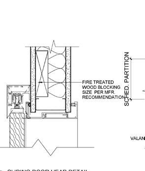
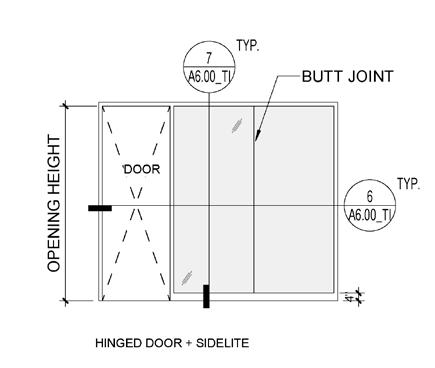

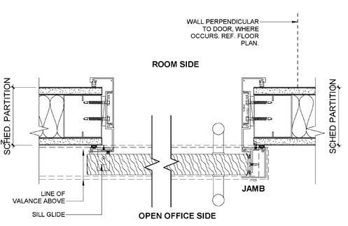
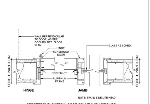
3-5/8" MTL STUD @ 16" OC. 5/8" GYP BD. UNDERSIDE OF (E) CONC SLAB MTL STUD RUNNER AND TRACK (E) CONC WALL TOP TRACK 5/8" GYP. BD. TYP. METAL CORNER TRIM STEEL STUDS @ 24" O.C. TYP. TYP. SOFFIT BRACING. REF. DETAIL SHT. MTL. SCREWS TYP. PER PLAN 3-5/8" MTL STUDS. REFER TO PARTITION LIMITING HEIGHTS TABLE ON THIS SHEET FOR STUD GAUGE AND SPACING SOUND BATT INSULATION UNDERSIDE OF CONC SLAB PLAN HEAD MTL STUD RUNNER w/ TRACK ACOUSTICAL SEALANT HINGED DOOR + SIDELITE DOOR AND FRAME TYPES - REFERENCE SCHEDULE FOR DIMENSIONS OPENING HEIGHT 7 A6.00_TI TYP. A6.00_TI SLIDING - SINGLE 18" CLEAR OPENING HEIGHT OPENING WIDTH DOOR- SINGLE GLAZED FULL HEIGHT C L R 1 0 DOOR 4" BUTT JOINT GLASS AS SCHEDULED 4 T R M 1 1/2" SCHE'D PARTITION BLOCKING AS REQ'D ALUMINUM FRAME ALUMINUM FRAME CARPET DOOR MUTE SCHEDULED DOOR S C H E D P A R T I T O N WALL PERPENDICULAR TO DOOR, WHERE OCCURS. REF. FLOOR PLAN. S C H E D P A R T I T O N ALUMINUM FRAME HINGE HINGE JAMB NOTE: SIM. @ SIDE LITE HEAD GLASS AS SCHED. FIRE TREATED WOOD BLOCKING SIZE PER MFR. RECOMMENDATION JAMB WALL PERPENDICULAR TO DOOR, WHERE OCCURS. REF. FLOOR PLAN. S C H E D P A R T I T O N OPEN OFFICE SIDE VALANCE ABOVE SILL GLIDE 1x4 WD TRIM (AROUND ALL 4 SIDES OF OPENING) EXTERIOR INTERIOR CL PER PLAN 26 " C 1 1 / 2 3/4" PLYWOOD W/ PLAS. LAM. FINISH GROMMET, DOUG MOCKETT PS SERIES 1 TOTAL, COORDINATE LOCATION W/ ARCHITECT RAAKS FLUSH MOUNTED EH-18-18 FM BRACKETS (2/ SHELF), 12" FROM EDGE. GC TO COORDINATE STUD SPACING OR PROVIDE ADDITIONAL STUDS AS NEEDED. 3-5/8" STUDS Project Number Scale: Issue Date Phase Print Date: CLIENT: 1420 Sutter St San Francisco, CA 94109 T 415.391.7918 F 415.391.7309 TEFarch.com Rabin Management Company 21 Locust Avenue, Suite 1 Mill Valley, CA 94941 T 415.522.5700 As indicated 3/4/2021 5:22:19 PM TAPSCOTT BUILDING 21806.00 02/04/21444 19TH STREET OAKLAND, CALIFORNIA 94612 1/4" = 1'-0" 1 DOOR & FRAME TYPES 3" = 1'-0" 7 STOREFRONT SYSTEM -HEAD & SILL 3" = 1'-0" 6 STOREFRONT SYSTEM-DOOR FRAME WITH SIDELITE 3" = 1'-0" 5 SLIDING DOOR HEAD DETAIL 3" = 1'-0" 8 DETAIL @ WINDOW TRIM DETAIL No.Date Description 703.04.2021100% CD PERMIT SET 1 1/2" = 1'-0" 9 WORK SURFACE W/ GROMMET, OFFICES Second Floor View East Open Office Elevation Large Conference Room Elevation Details Details
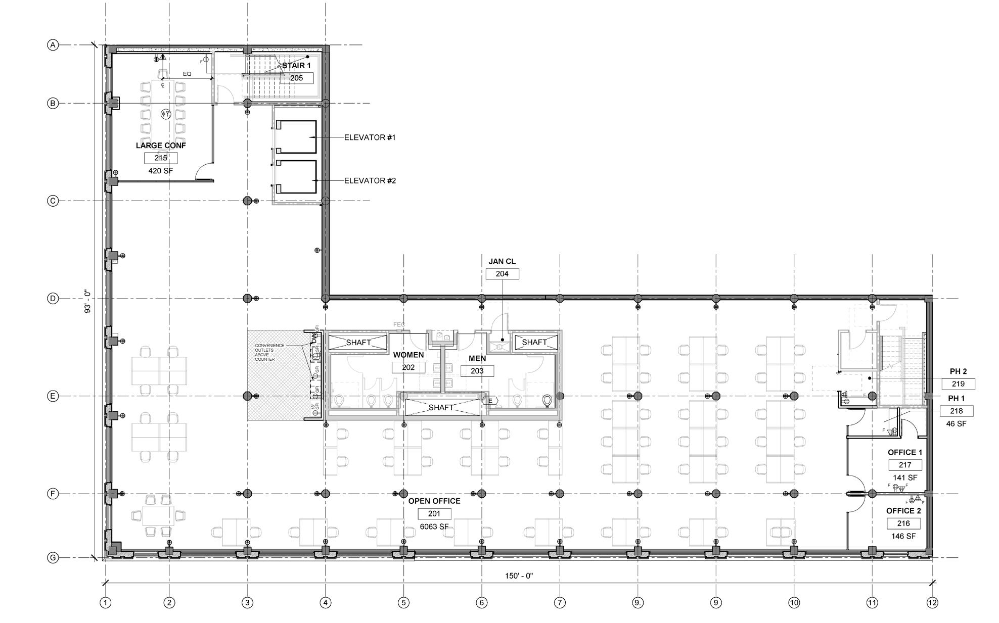
Second Floor RCP Plan
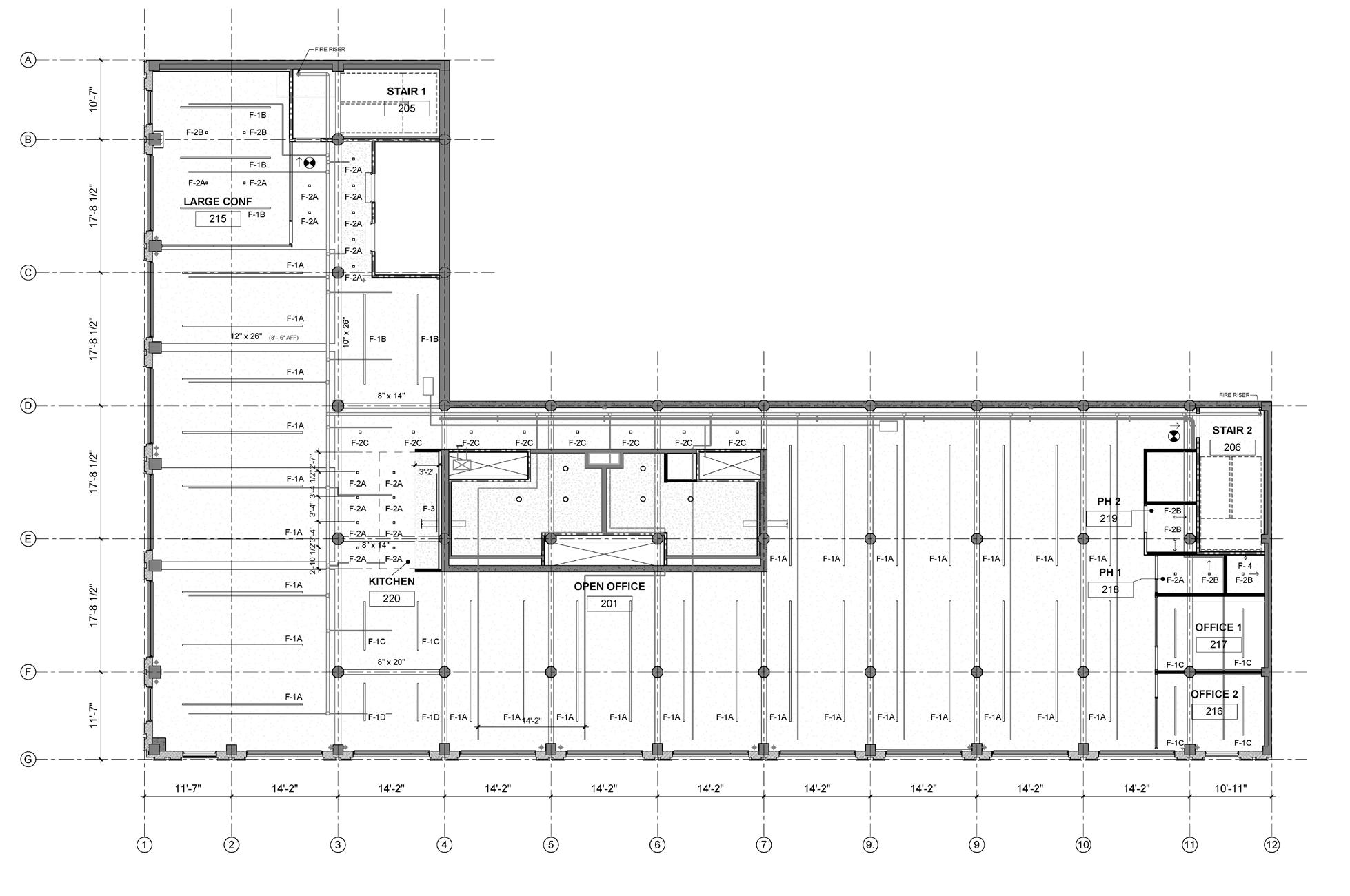
Second Floor Electrical and Furniture Plan
Declaimer: All the drawings in this project belong
TEF Design
to

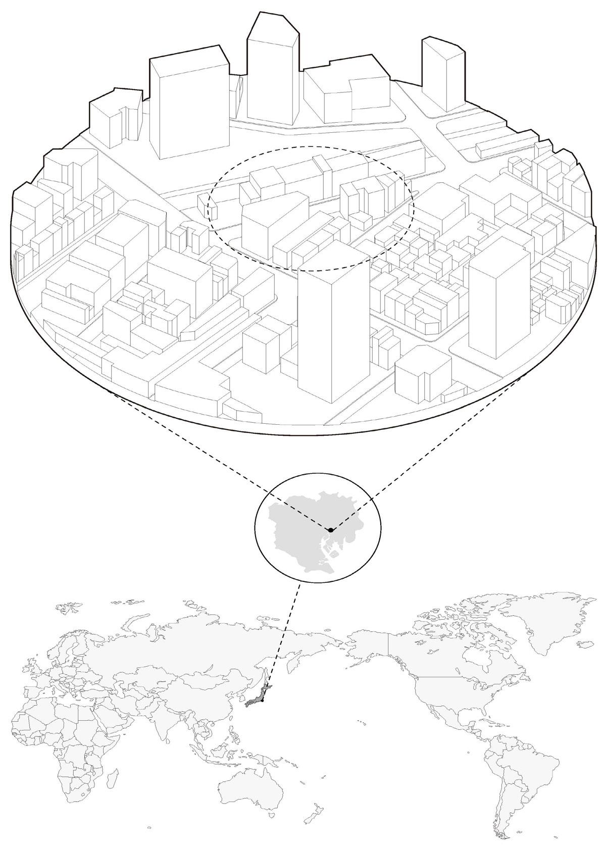
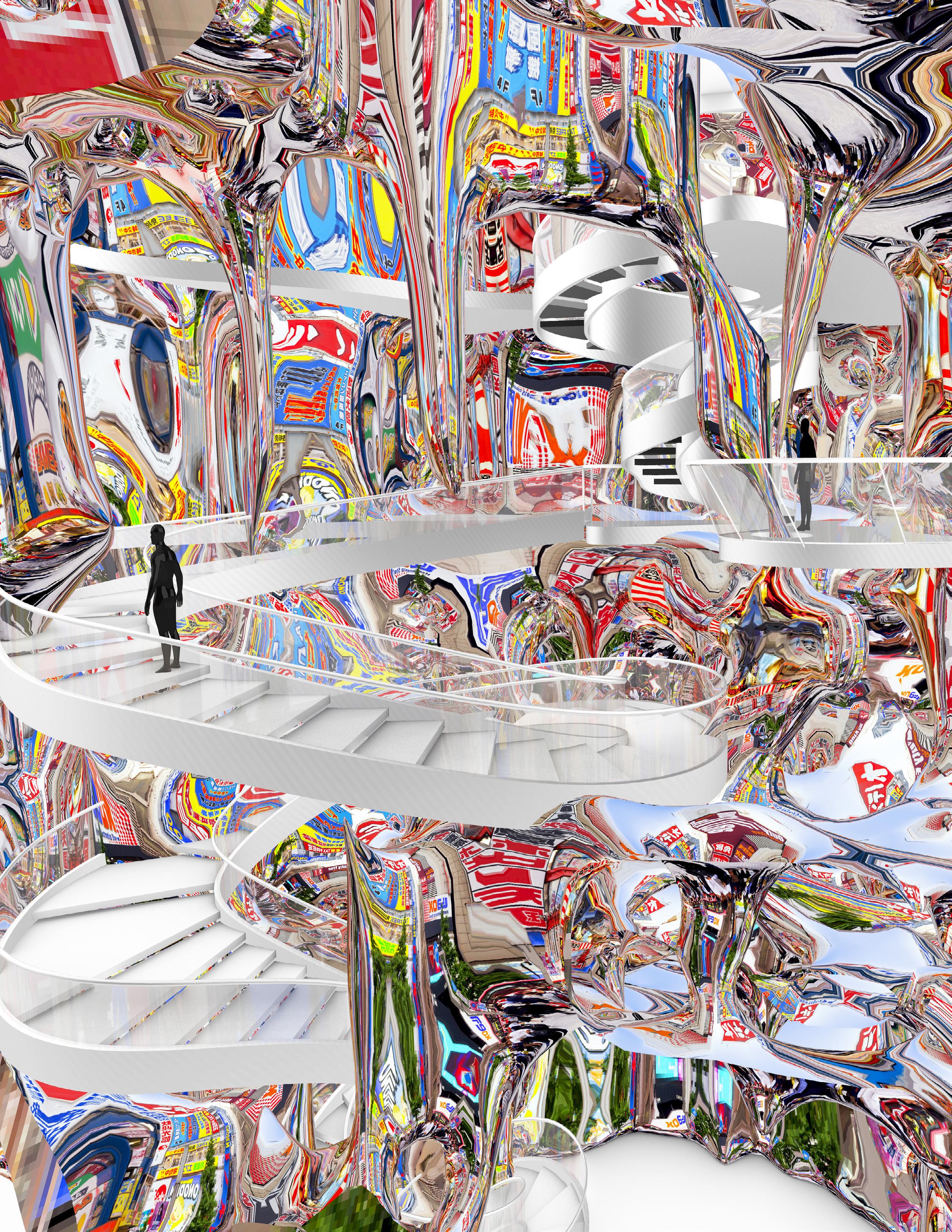
IMMERSIVE ILLUSION
Instructor: Matias Del Campo & Sandra Manninger
Group: Varalikaraj Singh, Kelvin Chen & Mengyang Wang
In today’s world of Data, where everyone is surrounded by it, we feel it is important to connect the data to the real world because it influences not just at the urban scale but also at the global level. This can be achieved by creating an interactive virtual environment through architecture. The idea is to go beyond virtual contextualization by creating an interactive virtual environment through reflection and artificial intelligence. Going back in history, the first virtual image created was through reflection, which changed the path of art and architecture, be it Arnolfini portrait or the House of Mirrors, Prague by Harold Davis. Seeing how vital reflection was crucial in changing the path of architecture in past, it is necessary to explore how it would affect the virtual environment and architecture of the future. To investigate this possibility, we used an image as our source of data because we feel it is a powerful way of expression and one of the most readily available data found among every human being. In order to get a perception of this data from the image, we developed artificial intelligence which helped us to transform data into an interactive virtual environment.
ITERATIONS
VISITOR IMAGE CAPTURED BY PROPLE
Image Captured by People Mobile App System Processing Visitor Artificial Intelligence
MOBILE APP
SYSTEM PROCESSING
ARTIFICIAL INTELLIGENCE
ILLUSION EXPERIENCE VIRTUAL IMAGE
IMAGES
CITY / DAILY LIFE PHOTO
IMAGE GENERATION OBJECT
SHOOTING
GRADE
City/Daily Life
Object Generation Image Virtual
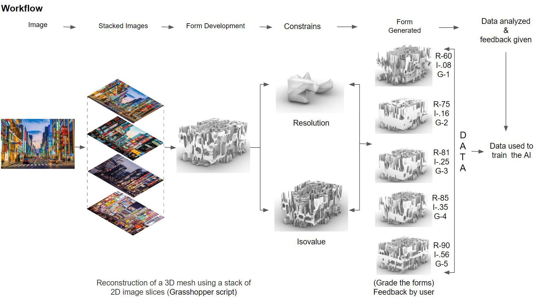
Workflow
Photo
AI Resolution Iso - Value
Feedback by User D A T A R-60 I-.08 G-1 R-75 I-.16 G-2 R-81 I-.25 G-3 R-85 I-.35 G-4 R-85 I-.56 G-5
Grade
Image Illusion Experience
IMAGE STACKED
FORM DEVELOPMENT CONSTRAINS FORM GENERATED DATA ANALYZED & FEEDBACK GIVEN
Shooting DATA USED TO TRAIN
Reconstruction of a 3D Mesh using of 2D image
(Grade the form)
Location: Tokyo, Japan
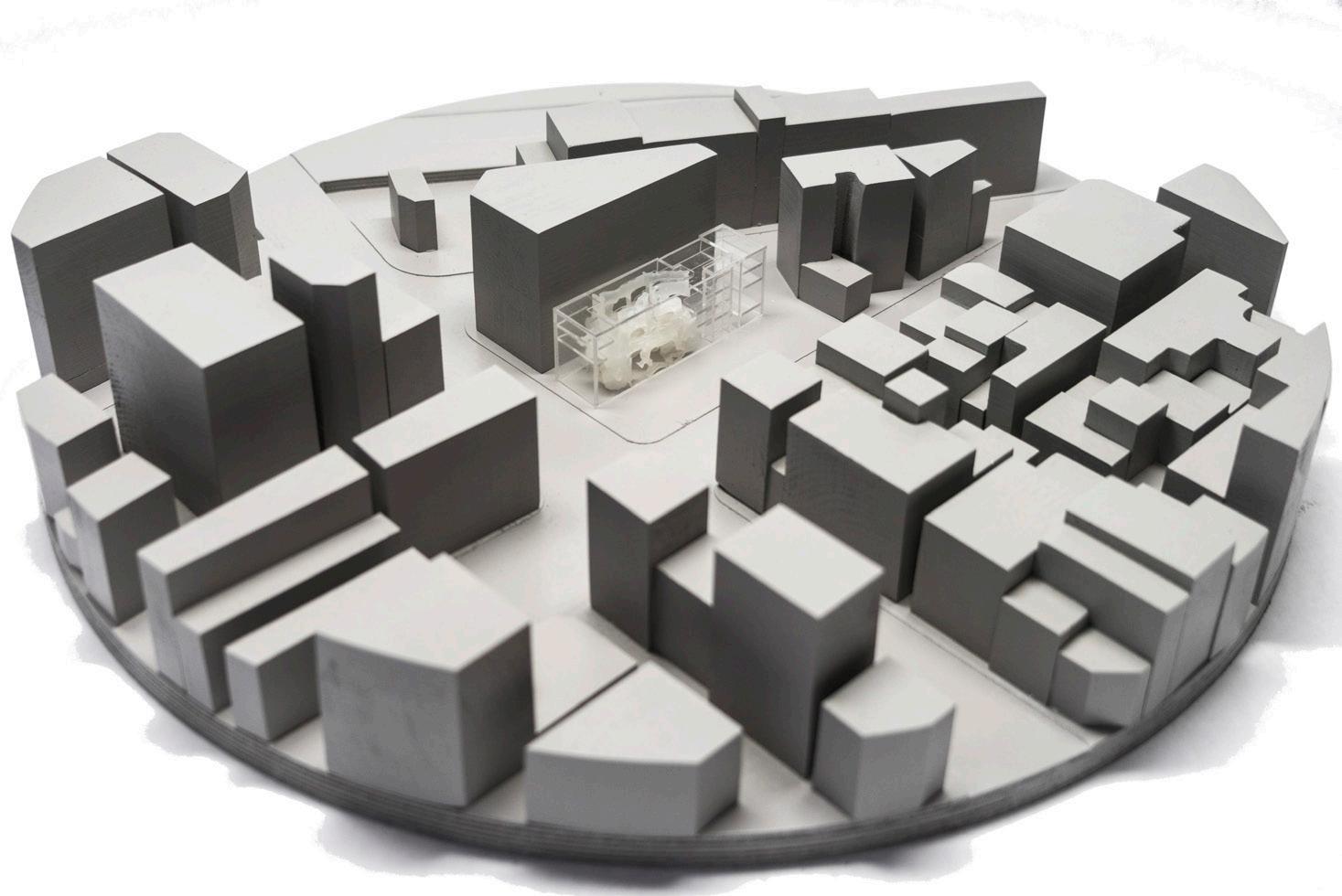

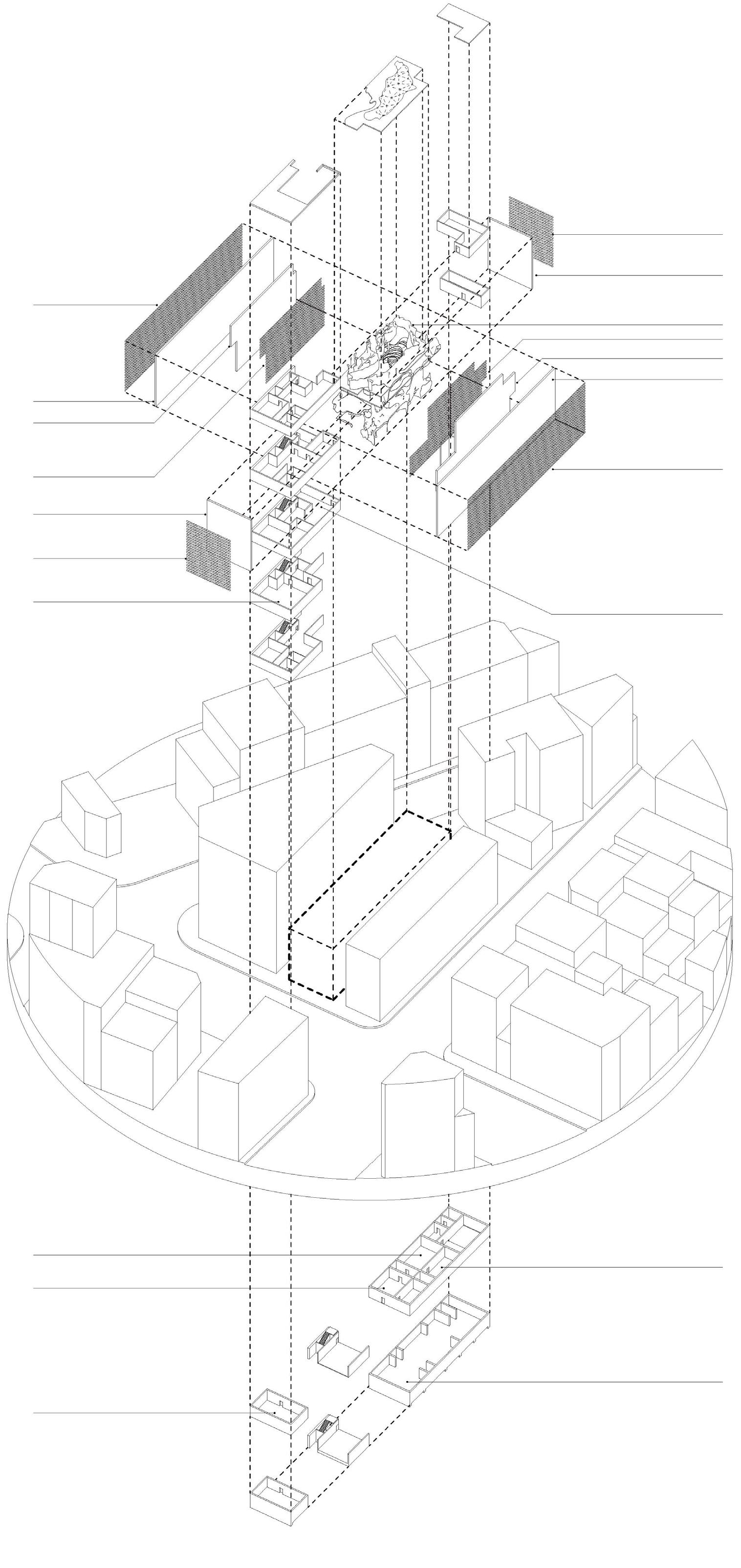
LED Media Facade Exterior Wall Mirror Sculpture LED Media Screen Inner wall Exterior Wall LED Media Facade VR Gallery LED Media Facade Exterior Wall Inner Wall LED Media Screen Exterior Wall LED Media Facade Immersive Experience Gallery VR Gallery VR Gallery VR Gallery Immersive Experience Gallery VR Gallery
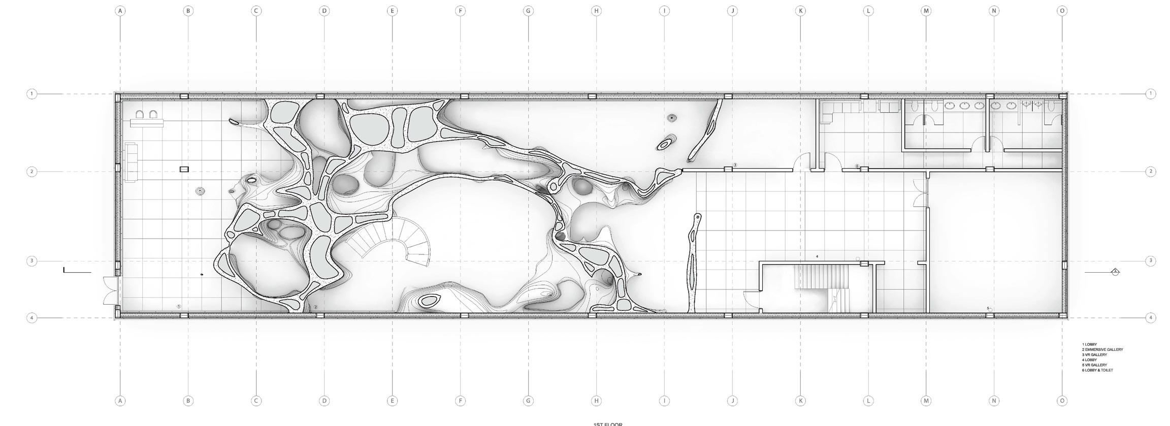
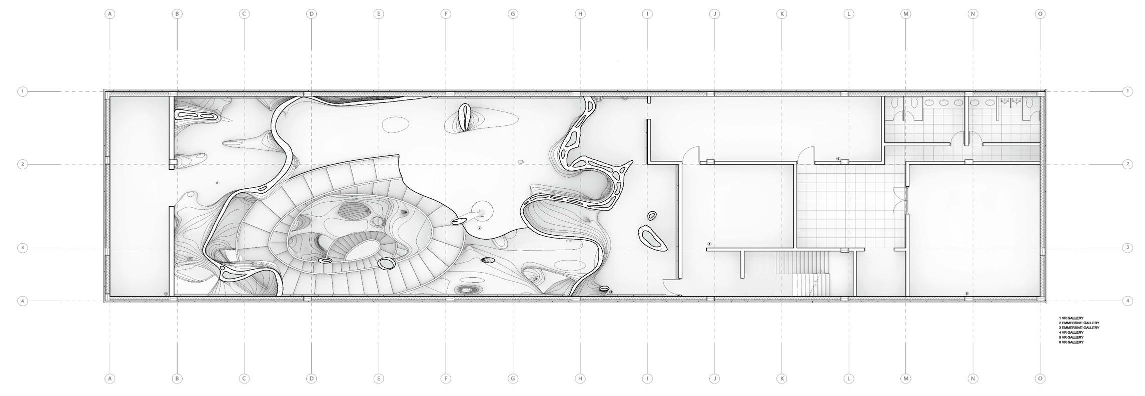
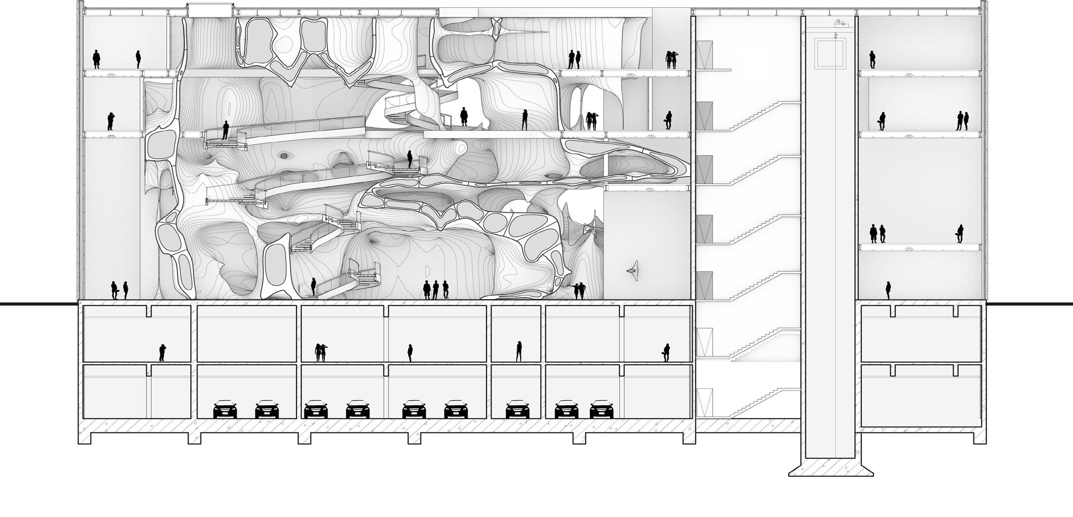
Floor Plans and Section
Thank You! Contact Information: (Ph) +1 734 846 9926 (e) varalikarajsingh17@gmail.com