

OPERATIONS MANUAL

"A NEW JOURNEY BEGINS FROM A LOVE FOR THE SEA”
(info@marineconsultants.nl) for
(akan@dumrul.com)
1 SUMMARY
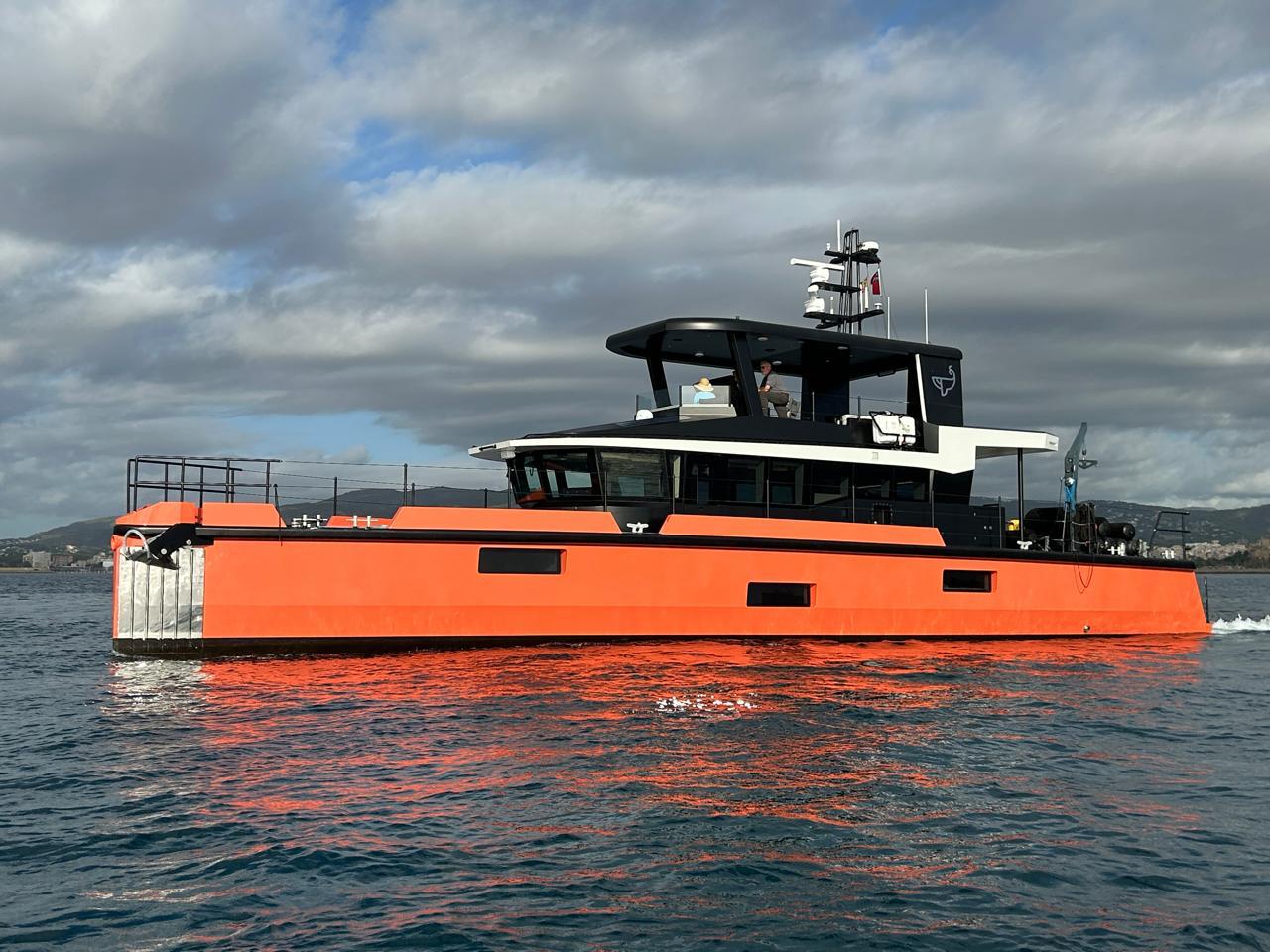
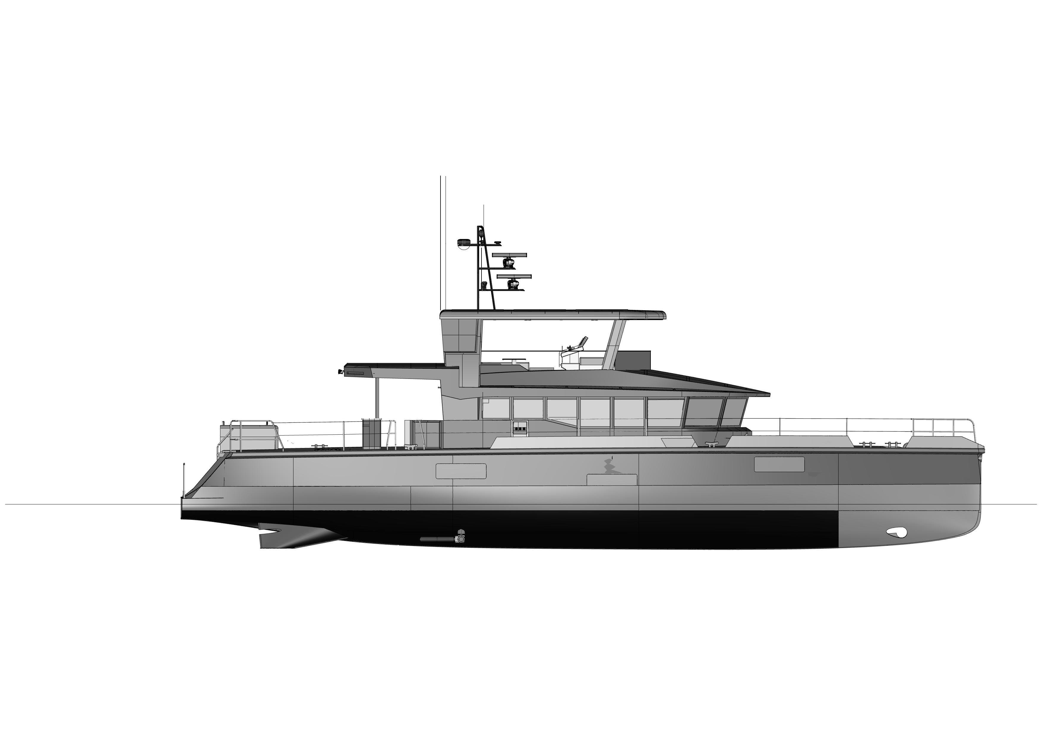
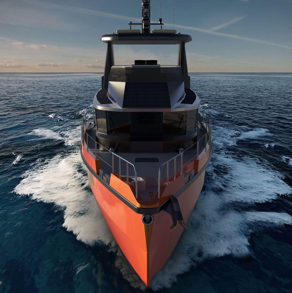
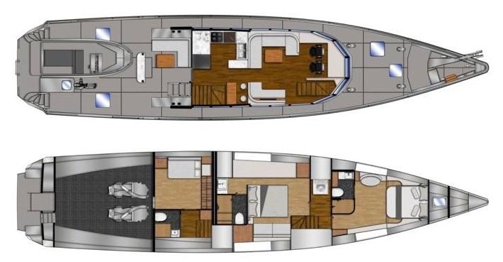
The Vanguard Explorer Yacht OperaVons Manual provides essenMal guidelines for the safe operaMon and maintenance of this 23.86m diesel-electric hybrid vessel, built for long-range exploraMon.
Key SpecificaVons:
•
• 9.5 knots; max speed 10.5 knots; range 3000-3500 NM.
• : 9,885 liters of fuel, 7,500 liters freshwater, and black/grey water tanks.
Power & Propulsion:
• : John Deere diesel engine with Praxis hybrid drive allows diesel or electric
• Electric Power: Powered by 2x 60kWh LiPO ba^eries and a 6kW solar array. The yacht can use shore power (single/three-phase) and solar to charge the ba^eries.
Safety Systems:
• Fire Safety: Portable exMnguishers, a Praxis fire alarm system, and emergency shutoff controls.
• Bilge Pumps: Electric, manual, and emergency fire pumps for water management.
• Stabilizers & Thrusters: DMS Magnusmaster stabilizers and a 15kW bow thruster ensure stability and maneuverability.
Water & Waste Management:
• Freshwater: 7,500 liters stored in four tanks, replenished by a Delfin water maker.
• Waste: Grey and black water systems with regular biocide treatment to avoid blockages.
Anchoring & Mooring:
• Anchors: 110kg Rocna with 100m chain, and a secondary Fortress anchor. Controlled via windlass and af kedging winches.
Environmental Protocols:
• Strict guidelines on fuel spillage, noise, emissions, and waste disposal to protect marine environments.
Overall, the manual emphasizes rouMne maintenance, safety checks, and environmental responsibility for the smooth and efficient operaMon of the yacht.
www.Exploreryacht.com for the journey. Page 6 of 102
2 INTRODUCTION
This manual has been compiled to help you to operate your boat with safety and pleasure. Please read it carefully and familiarize yourself with the boat before using it.
This owner's manual is not a course on boaMng safety or seamanship. If this is your first boat, or if you are changing to a type of boat, you are not familiar with, for your own comfort and safety, please ensure that you obtain handling and operaMng experience before “operaMng” the boat. The naMonal sailing federaMon or yacht club will be pleased to advise you of local sail training schools, or competent instructors.
Ensure that the anMcipated wind and sea condiMons will correspond to the design category of your boat, and that you and your crew are able to handle the boat in these condiMons.
Even when your boat is categorized for them, the sea and wind condiMons corresponding to the design categories A, B and C range from severe storm condiMons for category A, to strong condiMons for the top of category C, open to the hazards of a freak wave or gust. These are therefore dangerous condiMons, where only a competent, fit and trained crew using a well-maintained boat can saMsfactorily operate.
Do not exceed the maximum recommended load (see secMon 2.5) as this could subject the boat to excessive loads with possible structural damage. The reduced freeboard will also increase the risk of flooding in sever condiMons.
This owner's manual is not a detailed maintenance or trouble-shooMng guide. In the case of difficulty, refer to the boat builder or his representaMve. If maintenance manuals are provided, use it for the boat's maintenance.
Always use trained and competent people for maintenance, repairs or modificaMons. ModificaMons that may affect the safety characterisMcs of the boat should be assessed, executed and documented by competent contractors. The boat builder cannot be held responsible for modificaMons that he has not approved. In some countries, a license or authorizaMon are required, or specific regulaMons are in force that must be met before operaMng the boat.
Always maintain your boat properly and make allowance for the deterioraMon that will occur over Mme and because of heavy use or misuse of the boat.
Any boat, no ma^er how strong it may be, can be severely damaged if not used properly. This is not compaMble with safe boaMng. Always adjust the speed and heading of the boat to suit the sea condiMons.
Your boat is fi^ed with a life rafs, carefully read its operaMng manual. The boat should have onboard the appropriate safety equipment (lifejackets, harness, etc.) according to the type of boat, weather condiMons, etc. This equipment is mandatory in some countries. The crew should be familiar with the use of all safety equipment and emergency maneuvering (man overboard recovery, towing, etc.), sailing schools and clubs regularly organize drill sessions.
All persons should wear a suitable buoyancy aid (life jacket/personal floataMon device) when on deck. Note that, in some countries, it is a legal requirement to wear a buoyancy aid that always complies with their naMonal regulaMons
Keep this manual in a secure place, and hand it over to the new owner if or when you sel
3 DEGREE OF HAZARD AND CORRESPONDING SAFETY LABELS
The following degree of hazard and corresponding safety labels are used in this owner’s manual.
DANGER: Denotes that an extreme intrinsic hazard exists which would result in high probability of death or irreparable injury if proper precauMons are not taken.
WARNING: Denotes that a hazard exists which can result in injury or death if proper precauMons are not taken.
CAUTION: Denotes a reminder of safety pracMces or directs a^enMon to unsafe pracMces which could result in personal injury or damage to the craf or components or to the environment.
See also Chapter 13 “Symbols and safety warnings” for other safety labels used on VANGUARD
4 GENERAL INFORMATION AND CRAFT DATA
4.1 MANUFACTURER
Name of the model (type): VANGUARD Explorer Yacht
Builder/OWNER: VANGUARD XPM LLC
Address: 454 Old Landing Road Bluton SC 29910, USA
Website: www.exploreryacht.com
Email: chris@exploreryacht.com
Phone: +1 281 630 3513
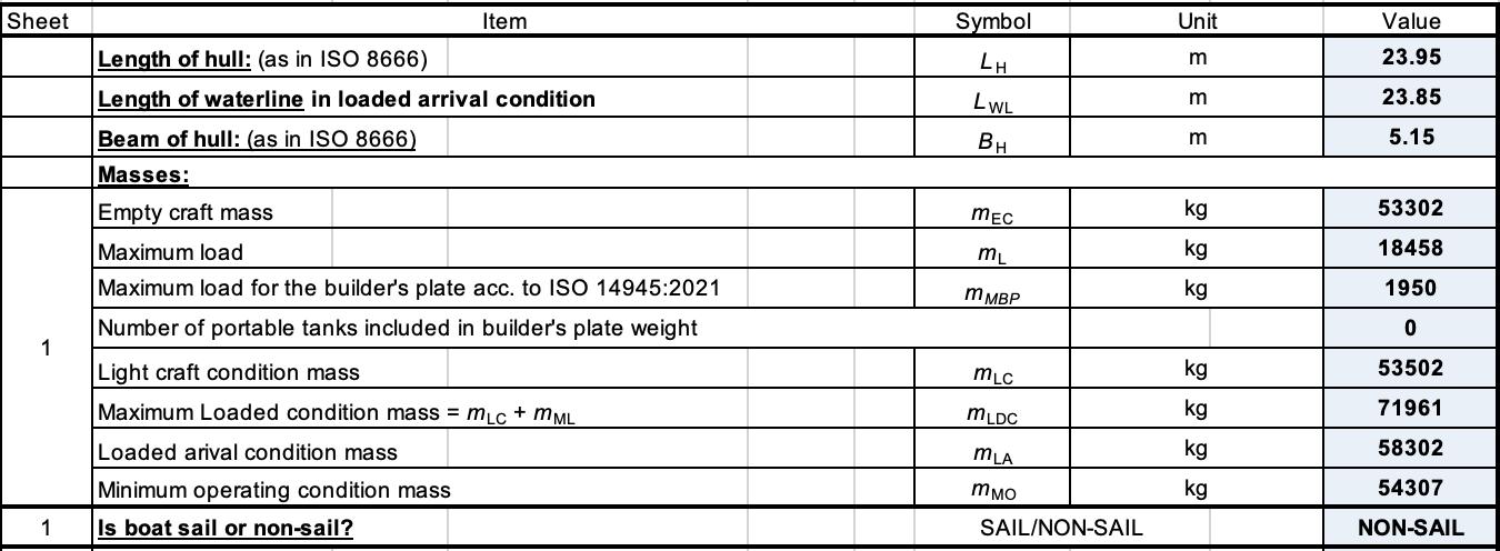
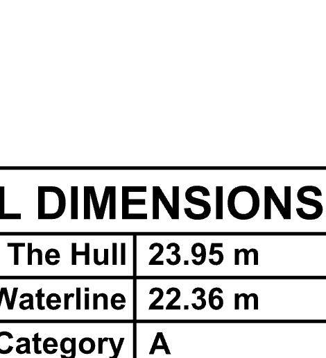
4.2 MAIN DIMENSIONS
4.4 DRAFTS
Maximum height (air draf), in the light craf condiMon: 8.15 meter
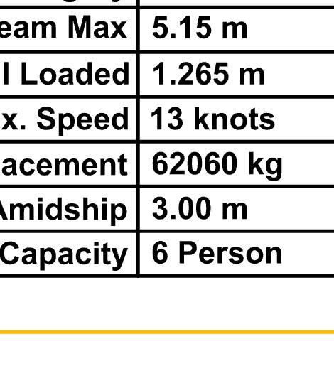
Maximum draf, in the fully loaded condiMon: 1.265 meter
4.5
MASS OF THE CRAFT
Light craf condiMon: 53,502 kg
Maximum load note 1): 15,000 kg +
Maximum load condiMon mass: 68,000 kg
Note 1) See secMon loadings
4.6
TANK CAPACITIES
The weight of liquids, when all permanently installed tanks are in DEPARTURE condiMon, is 15,000 kg.
Tank No Capacity Notes
Fuel Tanks 7 9,885 Ltr Note 20% reserve in ARRIVAL condiMon.
FW Tanks 4 7,500 Lts Note – water ballast compensaMon as fuel used.
Grey Water Tanks 2 410 Ltr Note – pump regularly
Black Water Tanks 2 600 Lts
Gluycol Tanks (2) 400 Ltr 2 tanks joined in series, keel cooled

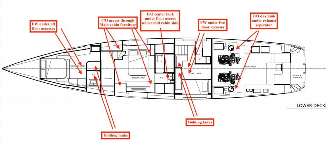
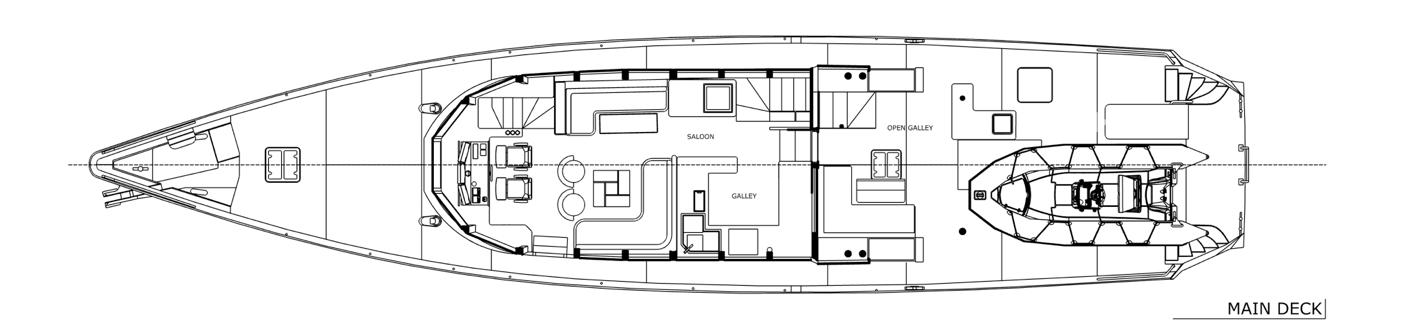
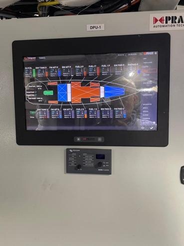
Tank levels are displayed on the Praxis MIMIC displays in the engine room, main helm and flybridge. Levels are measured using BEP Ultrasonic level gauges or Maretron pressure transducers. LocaMons of the tank gauges are as shown in the a^ached drawing.
CauVon: Not all of the water and fuel tank capacity should be used due to the trim and loading of the vessel. A 20% reserve FUEL should be kept in ARRIVAL condiMon
4.7 MAXIMUM RECOMMENDED LOAD
DESCRIPTION
PROVISIONS & PERSONAL EFFECTS
BOAT CARRIED ABOARD
MARGIN FOR FUTURE ADDITIONS
MASS COMMENTS
(6 PERSONS)
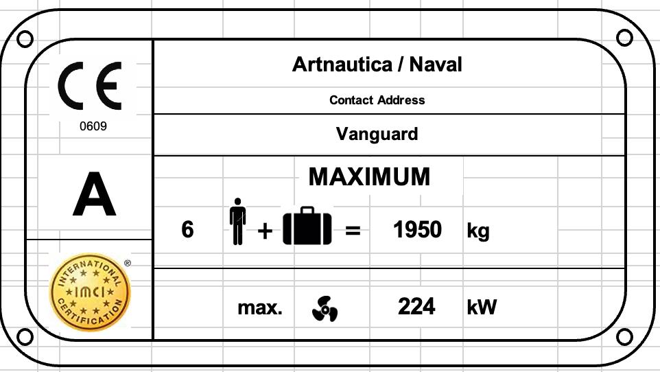
kg AS SHOWN ON BUILDERS PLATE
KG AS USED FOR STABILITY CALCULATION
Warning: When loading the yacht, never exceed the maximum recommended load. Always load the yacht carefully and distribute loads appropriately to maintain design trim approximately level. Avoid placing heavy weights high up.
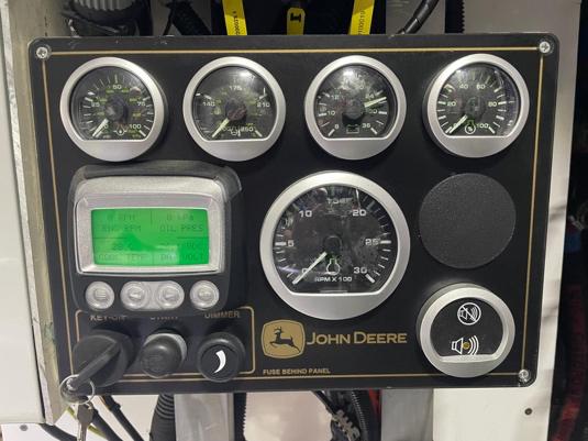
4.8 ENGINE DATA
Engine type:
Propulsion system:
Installed engine power:
Maximum recommended engine power:
John Deere 4045 AFM85 (M1 rated)
Diesel Electric Hybrid
Esco Power PHT 1.4: 1 step up hybrid drive
Twin Disc 2.5:1 step down marine gearbox Praxis 30/70kW motor /generator
235 kW [320 HP]
116 kW [160 HP, conMnuous]
4.9
ELECTRICAL DATA
4.9.1 DC SYSTEM (12 V / 24 V)
Capacity House ba^eries: 3 x7 kWh Ah / 24 V DC (LiPO) plus small navigaMon ba^ery backup.
Capacity Hybrid Power: 2 x 60 kW.H / 600 V DC (LiPO)
Capacity service ba^ery: 60 Ah / 24 V DC (Lead Acid deep cycle AGM)
4.9.2 AC SYSTEM (230 / 415VAC)
System:
Shore Power:
50 Hz @ 230VAC Single phase, 50Hz 415V AC Three phase
Single Phase 50/60Hz 5kW Three Phase 50/60Hz, 25KVA
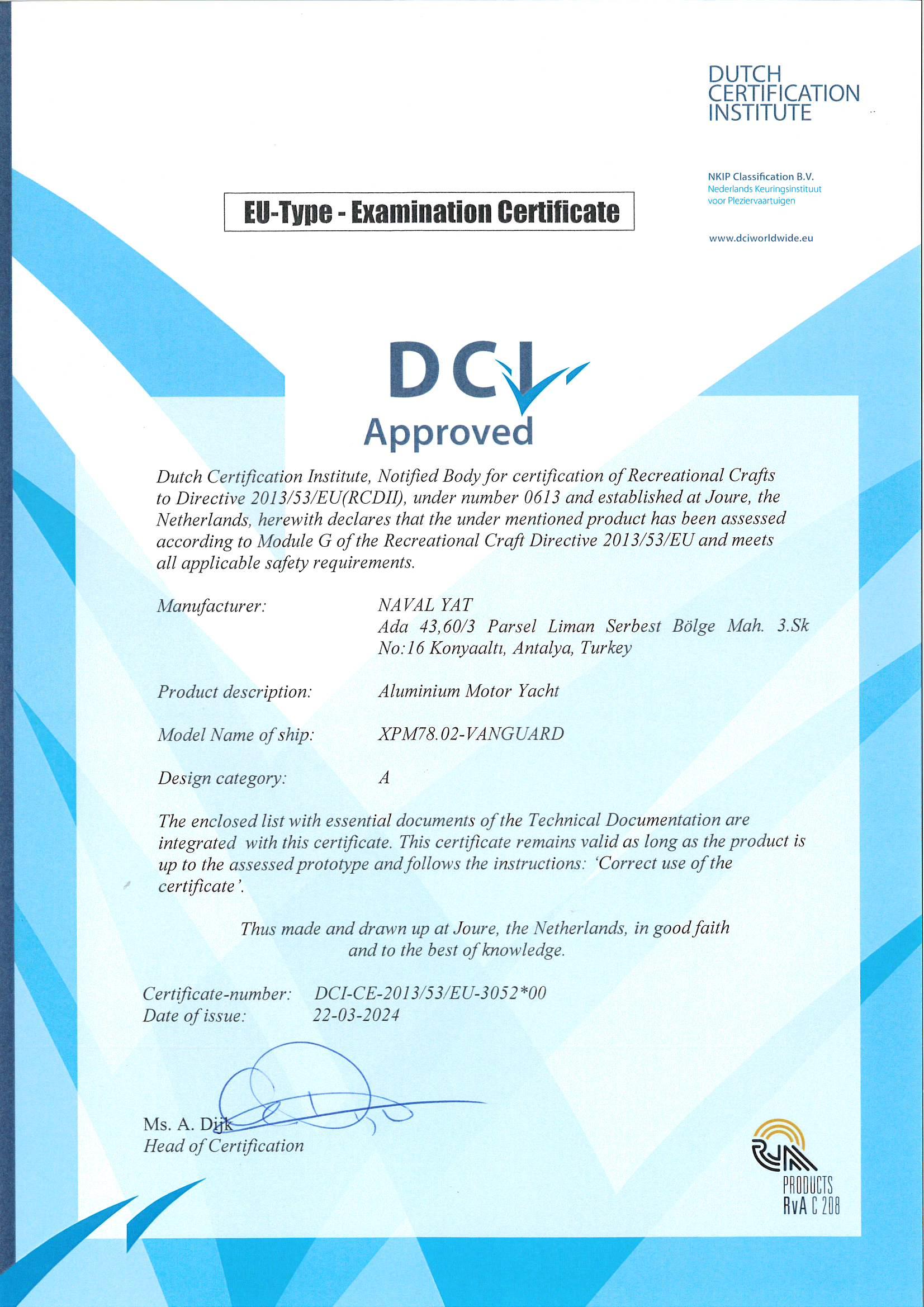
6 CERTIFICATION & DESIGN CATEGORY
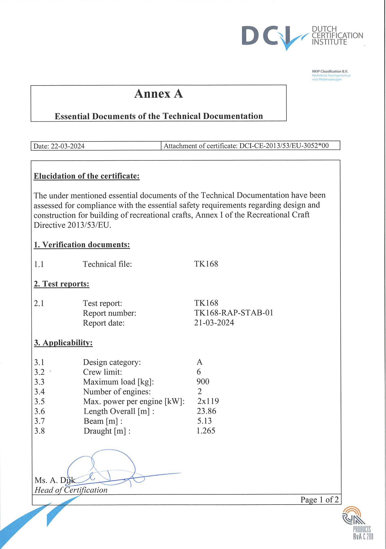
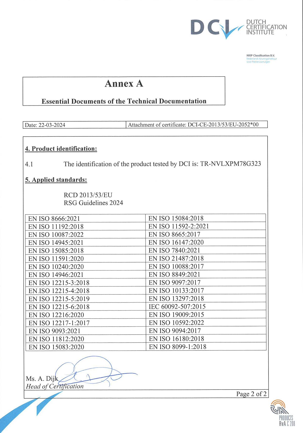
The VANGUARD is cerMfied according to the essenMal requirements of:
• EU RecreaVonal Craa DirecVve 2013/53/EU
• UK MCA Catergory (0) Code as specified in UK MGN 280 (Note 2).
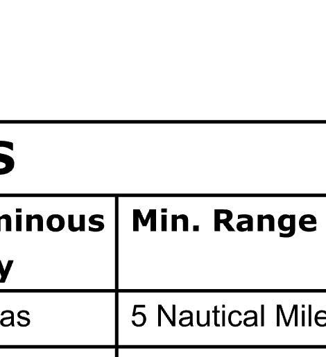
As shown on the builders plate the yacht is designed for operaMon in condiMons as described for DESIGN CATEGORY A
DESIGN CATEGORY A:
DESIGNED FOR EXTENDED VOYAGES WHERE CONDITIONS MAY EXCEED WIND FORCE 8 (BEAUFORT SCALE) AND SIGNIFICANT WAVE HEIGHTS OF 4 M AND ABOVE BUT EXCLUDING ABNORMAL CONDITIONS, AND VESSELS LARGELY SELFSUFFICIENT.
DESIGN CATEGORY B:
DESIGNED FOR OFFSHORE VOYAGES WHERE CONDITIONS UP TO, AND INCLUDING, WIND FORCE 8 AND SIGNIFICANT WAVE HEIGHTS UP TO, AND INCLUDING, 4 M MAY BE EXPERIENCED.
DESIGN CATEGORY C:
DESIGNED FOR VOYAGES IN COASTAL WATERS, LARGE BAYS, ESTUARIES, LAKES AND RIVERS WHERE CONDITIONS UP TO, AND INCLUDING, WIND FORCE 6 AND SIGNIFICANT WAVE HEIGHTS UP TO, AND INCLUDING, 2 M MAY BE EXPERIENCED.
DESIGN CATEGORY D:
DESIGNED FOR VOYAGES ON SHELTERED COASTAL WATERS, SMALL BAYS, LAKES, RIVERS AND CANALS WHEN CONDITIONS UP TO, AND INCLUDING, WIND FORCE 4 AND SIGNIFICANT WAVE HEIGHTS UP TO, AND INCLUDING, 0,3 M MAY BE EXPERIENCED, WITH OCCASIONAL WAVES OF 0,5 M MAXIMUM HEIGHT, FOR EXAMPLE FROM PASSING VESSELS.
Note 1 : The significant wave height is the mean height of the highest one-third of the waves, which approximately corresponds to the wave height es>mated by an experienced observer. Some waves will be double this height.
Note 2 : VANGUARD was designed and constructed to COMMERCIAL specifica>on under supervision of UK MCA to MCA Catergory (0), Unrestricted naviga>on to 80 degree N (Summer). A sample of the survey results is available for inspec>on. Several categories are not in compliance and these represent specific choice of the Owner as the vessel will not be used for commercial purposes. For example a fully compliant medical kit is not carried.
6.1 BUILDERS PLATE & WATER CRAFT IDENTIFICATION NUMBER
The WIN is fi^ed on the af deck above the rear saloon access door O.N.751204, R.T. 34.27 / 100
Warning: Do not exceed the maximum recommended number of persons. Regardless of the number of persons on board, the total weight of persons and equipment must never exceed the maximum recommended load. Always use the seats/seating spaces provided.
Warning: When loading the yacht, never exceed the maximum recommended load. Always load carefully and distribute loads appropriately to maintain design trim approximately level. Avoid placing heavy weights high up.
www.Exploreryacht.com for the journey. Page 16 of
7 INFORMATION REGARDING RISK OF FLOODING AND STABILITY
7.1 STABILITY DATA FOR SAILING & MOTOR YACHTS
Compliance with the stability criteria does not ensure immunity against capsizing regardless of the circumstances or absolve the owner of the yacht from his responsibiliMes. The owner should therefore exercise prudence and good seamanship having regard to the season of the year, experience of the crew, weather forecasts and navigaMonal zone, and should take appropriate acMon as to speed, course and sail sezng warranted by the prevailing condiMons.
Before a voyage commences care should be taken to ensure that sizeable items of equipment have been properly stowed to minimise the possibility of both longitudinal and transverse shifing under the effect of acceleraMons caused by pitching and rolling. In adverse weather condiMons and when there is the possibility of encountering a severe gust, squall or large breaking wave, all exposed doors, hatches, skylights, vents, etc. should be closed and securely fastened to prevent ingress of water.
Stability recommendaVons:
- All crew members need to be adequately trained.
- Any change in the disposiMon of the masses aboard (for example the addiMon of a fishing tower, radar, a stowing mast, change of engine, etc.) may significantly affect the stability, trim and performance of the boat;
- Stability is reduced by any weight added high up of slack bilges;
- In rough weather, hatches and lockers should be closed to minimize the risk of flooding;
- Stability may be reduced when towing or lifing heavy weights using a davit or boom;
- Breaking waves are a serious stability hazard.
7.2 SIGNIFICANT STABILITY INFORMATION
• Downflooding Angle: 58 degrees (limited by engine room vent openings)
• Maximum RighMng Moment: @ 45 degrees
• Angle of Vanishing Stability: >>70 degrees (range of calculaMon typically >90)
CauVon: Before leaving the harbour please make sure that engine room exterior hatch, deck hatches, the salon rear hatch and pantograph doorclosed.
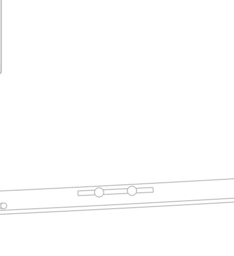
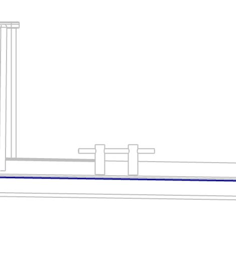
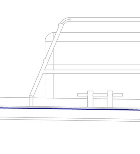
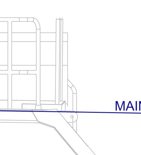
7.3 LOCATION OF THROUGH HULL FITTINGS.
The drawing added to this manual below show all through hull fizngs installed in the hull
• All overboard discharge through hull fizngs extend above the waterline and can be maintained afloat
• Main sea sucMon fizngs are equipped with shut off bu^erfly valves and fully redundant for maintenance at sea.
Familiarize yourself with the locaMon of this through hull fizngs and inform your crew before leaving the harbor In case of an emmergency these seacocks should be found easily.


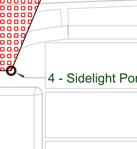
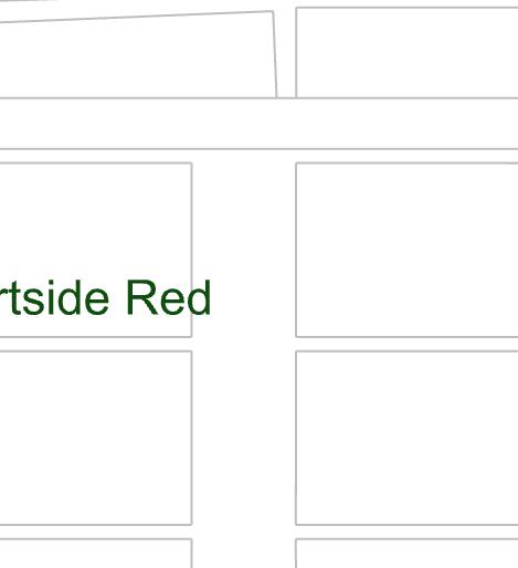
LocaMon of through hull overboard discharge fizng
LocaMon of through hull sea sucMon
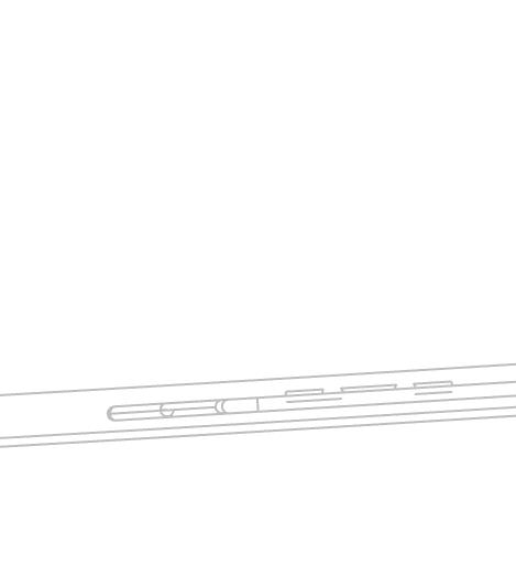
7.4 WATERTIGHT CLOSURES
All enclosures are fi^ed with Microswitches and displayed on the Praxis MIMIC - SAFETY.


LocaMon of waterMght doors. Note: Pantograph door fi^ed with a washboard for use at sea.
LocaMon of waterMght hatches. Note: FOREPEAK & SWIM PLATFORM MUST BE CLOSED at sea.
CauVon: Keep port lights, windows, washboards, doors, hatches or venMlaMon openings closed when appropriate, e.g. in rough weather.
www.Exploreryacht.com for the journey. Page 19 of 102
8 SYSTEMS & INSTALLATIONS
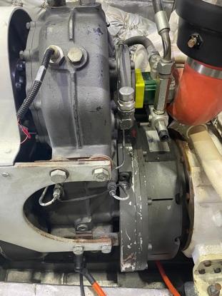
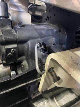
8.1 ENGINE AND HYBRID DRIVE
VANGUARD is equipped with a fully redundancy diesel electric hybrid drive. This secMon will concentrate on a single engine, the addiMonal engine is a repeat. Refer also to different secMons in this Manual on Fuel system, Ba^eries, Praxis Power Management …..
VANGUARD can operate on a single or twin engines.
• Trim for good fuel consumpMon is slightly by the stern. Trim by the bow will cause the bow to dig in, excessive stern trim will result in instability and increased rolling.
• Sweet spot for a single engine is 7.5-8.5 KN in calm weather 80/90% full load. This is the most efficient sezng for fuel consumpMon which should approximate to 3.5 L/NM in calm weather with stabilizers retracted.
• Two engines will be required for greater speed or in more challenging weather. Two engines will also be required when the electrical load is high such as when using HVAC underway or charging the power ba^eries at higher rates. The sweet spot for this configuraMon is 8.59.5KN 60/70% load on each engine. Expect fuel consumpMon to increase to something a round 4.5L/NM.
www.Exploreryacht.com for the journey. Page 20 of 102
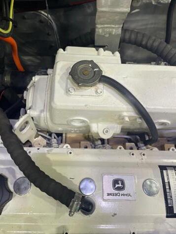
Engine – this is a John Deer 4 cylinder turbocharged diesel engine. Full power is 112kW or 160BHP. Engine is M<1 rated for conMnuous operaMon at 100% load with a 60% fuel factor (meaning average fueling is 60% or maximum taken over Mme).
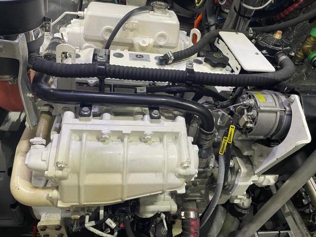

Hybrid Drive - The engine is connected via a mechanical clutch to an Esco Power step up of PHT drive. this allows drive to a 30kW Praxis DC motor at a step-up raMon of 1.4:1.
The motor spins faster than the engine crankshaf. This motor will also act as a 30-70kW generator either when driving the propeller or when decoupled from the prop shaf. The Escopower drive is rated to 250BHP power transmission.
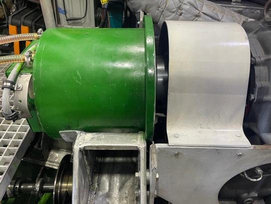
Gearbox – The hybrid drive also transmits power to the Twin Disc gearbox. The gearbox has a reducMon raMo of 2.5:1 and 5 degrees down angle. It provides Forward, Neutral and Reverse. The gearbox is rated to 250HP power transmission.
www.
StarVng & stopping the engine
StarMng the engine
1. Check oil levels when staMonary for engine, PHT drive and gearbox (see above for locaMons).
2. Check engine coolant level (glycol – see above for locaMon)
3. Check sea water intake is open at the filters between the engines
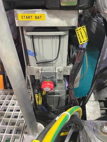
4. Power the starter ba^ery
5. Switch Clutch controls to “Praxis”
6. Switch on a single engine room extractor fan
7. Select fuel day tank (P or S) and check level is sufficient.
8. Switch on fuel priming pump, when lights stabilize press START.
9. Check engine is operaMng normally and without system leaks. Note: both engines are noisy when driving the hybrid system at idle. This is normal but there should be no excessive line vibraMon.
Stopping the engine
1. This is a reverse of the start procedure EXCEPT, engines control should be stopped at the HELM EMS before the engines ae themselves switched off.
2. Before stopping, allow engine a 10 minute cool down period afer running under load.

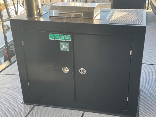
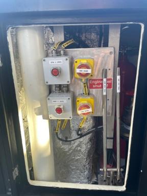
Emergency Stop.
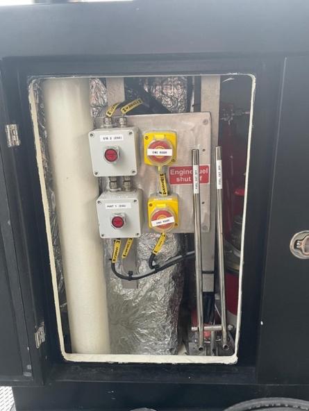
Emergency Stop is at the Muster StaMon on the Af Deck. There you will find:
• 2 fuel levelrs to cut of fuel supply from the day tanks.
• 1 bu^on to close Engine Room dampers to allow for release of exMnguishers
• 1 bu^on to release the fixed fire exMnguishers
• 2 bu^ons to isolate the Power Ba^eries
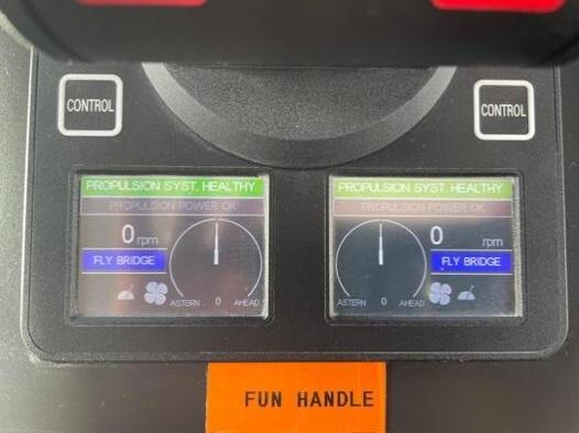
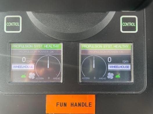
Taking control at the HELM.
1. Ensure thro^les are in the ZERO posiMon.
2. Select Wheelhouse or Flybridg control. This is achieved by pressing CONTROL on the EMS for either engine.
3. You now have control of the engines from the perMnent helm staMon.
4. Use either DIESEL or ELECTRIC when maneuvering but do not use both.
5. When underway, keep the power ba^eries permanently charged by pressing CHARGE. The system will automaMcally adjust prop/electric load to keep the ba^eries fully charged but not overpower the diesels for the load sezng.
Charging Power Bageries
1. CHARGE can also be used with the diesel running but the gearbox in neutral. This will charge the power ba^eries quickly with a maximum (present) sezng of 36kW combines house load and ba^ery charge. A typical use would be charging ba^eries at anchor. House ba^eries are charged from the 415V 3-phase grid and will be maintained automaMcally.
2. The EMS Single line MIMIC is convenient for viewing how the charge is progressing.
Please read the accompanying manual of the engine before using the VANGUARD. In these accompanying manual you can also find the procedure to operate the engine and the necessary maintenance.
A separate manual for the engines is provided with the boat. Please read this manual carefully.
Warning: When starting an engine prevent craft movement and/or propeller rotation. Make sure the gearbox control lever is in NEUTRAL position.
Safe operation instructions:
• Ensure the flow of cooling water (feel this at the exhaust muffler exit, it should stay cool.)
• Ensure that ventilation ducts are unobstructed.
Avoid contact of flammable materials with hot engine parts.
Caution! After starting the engine, we recommend to check the following:
• check if there’s water flowing out of the exhaust. By overheating (insufficient or no cooling), a warning light will light up on the engine panel and a loud sound will be heard. In that case, immediately shut off the engine and check if the seacock for the water supply is open (in the engine room, BETWEEN ENGINES). If necessary ask for help.
• all instruments and alarm displays of the engine and drive have to indicate normal values. Regularly review the instruments during navigation.
Warning: When working on or close to the engines it is recommended to disconnect the engine from the starting batteries to prevent accidental starting. This can be done by turning the engine power main switch into the OFF position. The switch is located at the starter battery for each engine.
www.Exploreryacht.com for the journey. Page 24 of 102
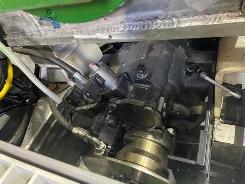
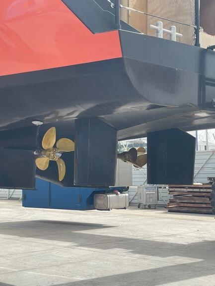
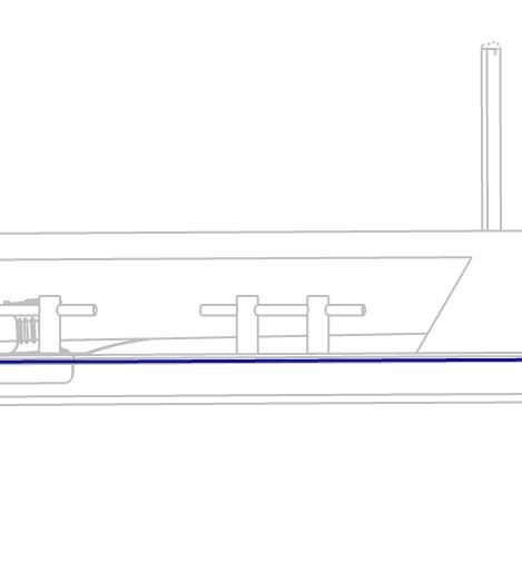
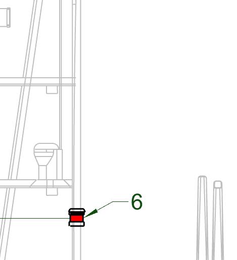
8.2 SHAFT LINE AND PROPELLER
VANGUARD is fi^ed with wo independent shafs and propellers. The assembly is as illustrated below. It is sea water lubricated using water from the diesel engine sea water pump. This is not available when using just electric drive with the diesel engine off, because of this use of only electric drive should be restricted to manoeuvering only.
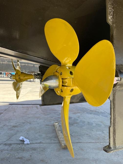
Specific items in the drive line include:
1. Sigmadrive self aligning bearing
2. Autolock shaf break (currently disabled)
3. PSS Pro water lubricated shaf seal
4. S/S shaf line
5. Phenolic cutlass bearing
6. Rope Cu^er
7. Varifold self tailing propeller
Note:
• Self-tailing propellers are employed to reduce resistance when operaMng on a single engine. They will windmill in the flow stream.
• Rope cu^ers are aligned to move with the shaf. Clearance fore/af must be allowed when fizng.

A separate manual for the drive line is provided. Please read this manual carefully.
www.Exploreryacht.com for the journey. Page 25 of
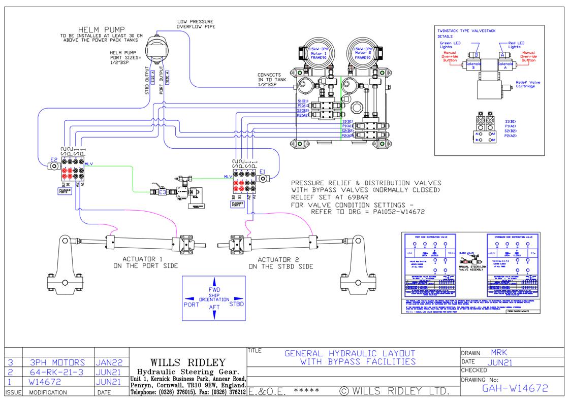
8.3 STEERING & BOW THRUSTER
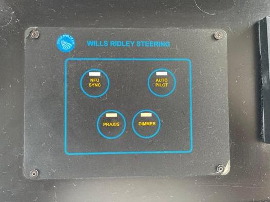
Steering is achieved by a fully redundant electro-hydraulic steering unit from Wills Ridley. This is integrated with a steering control system from Praxis AutomaMon to provide for the following funcMons:
FUNCTION
Emergency Hydraulic Steering
NFU Jog Lever
Local Control
FFU Steering
Autopilot
Full Dynamic Posi-oning
Loca-on
Descrip-on
Main Helm - WR – manual emergency hydraulic control.
Main Helm Flybridge - WR – on helm sta>ons
Engine Room
WR – on steering control box
Main Helm Flybridge - Praxis – wheel at both helm sta>ons
Main Helm Flybridge - Furuno – both helm sta>ons
Main Helm - Praxis – Main Helm
Two substanMal rudders are installed with the lower 1/3 acMng as a crush zone. Rudder pintles are 100% oversized and fi^ed with self-aligning Jeffra Pintle Bearings.
Please read the accompanying manual of the steering before using the VANGUARD. In these accompanying manual you can also find the procedure to operate the steering and the necessary maintenance. Below you will find a check list before operaMng and details for operaMng.
A separate manual for the Wills Ridely steering is provided with VANGUARD. Please read this manual carefully.
www.Exploreryacht.com for the journey. Page 26 of
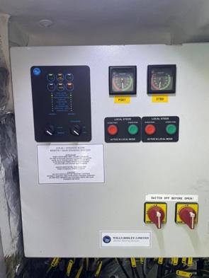
8.3.1 Star:ng the Steering and Selec:ng Steering Mode
• Switch on power at the stering control staMon in the Engine Room. Two switches ae provided, the cabiner cannot be opened when steering in live.
• Select “REMOTE”
• Select steering funcMon at the Main Helm fo Flybridge. Note: the “steering handover” between the two helm staMons is automaMc.
• Select PUMP 1 or 2 on the stering pump controller at the Main Helm. Note it is not possible to run two pumps at the same Mme.
Note Maximum swing for the rudder is 35 degrees each way
Modes are:
MODE Descrip,on
NFU SINC (WR Jog Lever)
Praxis (Wheel)
Autopilot (Furuno)
DP (Selected on the DP Unit)
8.3.2 Calibra:ng the Praxis Steering Controllers
Praxis Controllers provide for day-to-day steering funcVons plus commercial grade Dynamic PosiVoning. Fully independent control of each rudder plus twin propellers allows for thrust (Fore and Af) plus (P & S). Combined with a proporMonal control, long run Sidepower bow thruster, and VANGUARD can maneuver in very confined spaces.
Set end stop Limits and Zero
• Turn MIMIC to MIMICA/10 – 050 STEERING Sezngs
• Switch steering to LOCAL
• Adjust to HARD Port (back off 3 clicks). Use trackpad to press SET PS on both rudders
• Adjust to HARD STBD (back off 3 clicks).? Use Trackpad to SET SB on both rudders
• Adjust ZERO. Use trackpad to SET Zero on both rudders.
• Next sea trial to ensure VANGUARD steers in a straight line. If not then, switch to LOCAL and adjust both rudders to reset Zero.
Set Toe in or Toe out for minimum drag.
• Next in LOCAL mode adjust just one rudder to alter tow in.
• NoMce if speed increases or decreases or is unaltered.
• ConMnue to max speed (toe in or out) is opMmum.
• Reset ZERO.
8.3.3 Bow Thruster
VANGUARD is fi^ed with a 15kW, proporMonal control, long run, bow thruster from Sidepower. The breaker controls are in the forepeak, they are usually lef switched on. The thruster tunnel is fi^ed with grids on either side to limit the possibility of damage from floaMng debris.
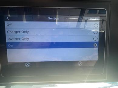
A 15kW unit is powerful and will tax the power supply capability within Vanguard. To ensure power is available it is advisable to switch the Victron MulMplus controllers to “Invert Only” and prevent power being drawn to charge the House Ba^eries.
This is achieved via the Victron Cerbo controller at the main helm staMon. Play with these controls to understand their working before needing this sezng in anger.
Aaer use, turn this back to RUN or the House Bageries will die at a future and inopportune moment!
The thruster can be operated three ways:
1. From either Helm using the proprietary S-Link Sidepower control system. This is a CAN-bus based system and is stand-alone from other communicaMons.
2. Via the Praxis commercial dynamic posiMoning system at the Main helm. CommunicaMon is hardwired via the I/O unit within the Engine Room VMS Cabinet.


3. Via the portable Dockmate controls allowing posiMoning from any locaMon on the deck CommunicaMon is WIFI between the hand-held controller and the Dockmate control box located at the main helm. This itself is hard wired to the Praxis DP System and exists outside of the normal scope for Dockmate support services (call Praxis).

Vanguard is a full 24m in length with a keel approximately ¾ of that. She responds slowly to bow thruster signals but will conMnue moving once in moMon. PracMce in open water to get a feel for the response before a^empMng operaMon in confined situaMons.
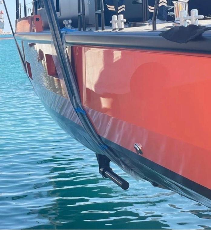
8.4 STABILISERS
VANGUARD is equipped with stabilizers from DMS Magnusmaster. These work on the magnus effect where rotaMng a cylinder in a flow stream produced a force at 90 degrees to the rotaMon, upwards or downwards depending on the direcMon of rotaMon.
These stabilizers use li^le power in operaMon. They fold automaMcally when not in use and are fi^ed with rope guards. Stabilizers are not always necessary depending on trim and sea condiMons. Switching them off will gain about 0.5KN of speed between 6/8 knots.
• Stabiliser breaker controls are on the Port side of the steering plaÅorm, near to the floors.
• Engage breaker before use.
• Stabilisers controls are at the helm staMon, Port side. They will be powered when the breaker is engaged.
• To check operaMon, go to the control screen when they are deployed and press <FORCED ROLL>. Rolling will stop when this bu^on is released, WARN CREW BEFORE DOING THIS.
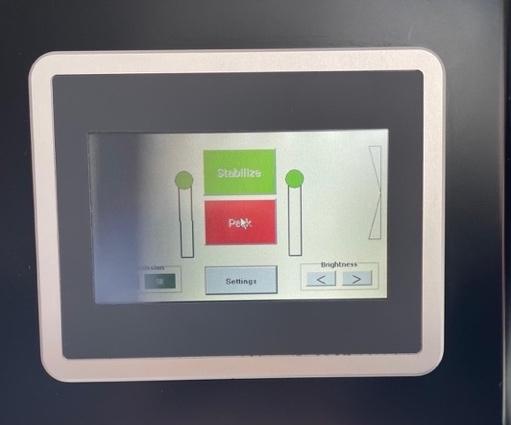
Deploying and Retrieving Stabilisers
• Stabilisers will only deploy when either (P or S) engine clutch is engaged.
• Press the Green <STABILIZE> bu^on and the image will show the stabilisers deploying.
• Stabilisers can be retrieved by pressing the Red <STOW> bu^on.
• Stabiliser will use energy. They should be docked in calm weather or when induced rolling is comfortable.
• Stabilisers are set to dock automaMcally when the clutch disengages, this prevents accidental damage when docking near to obstacles.


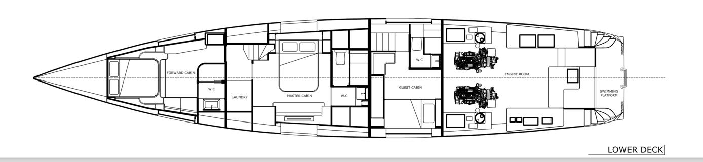
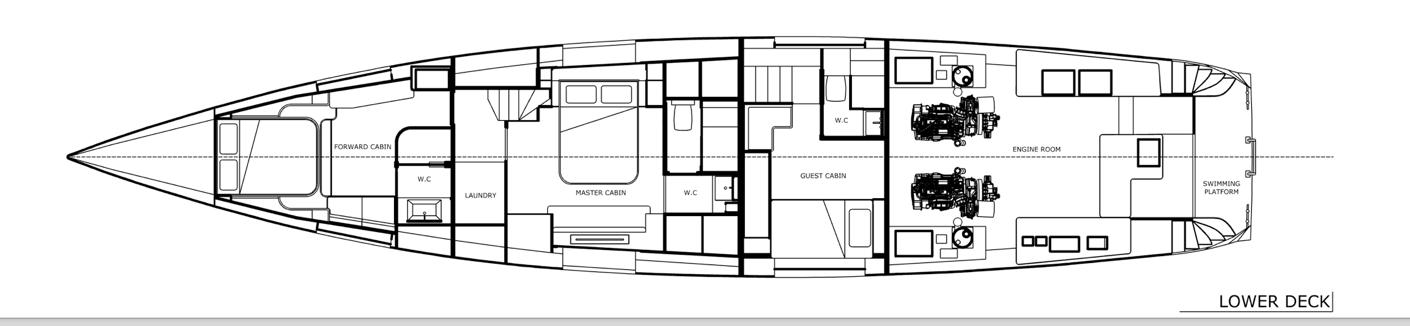
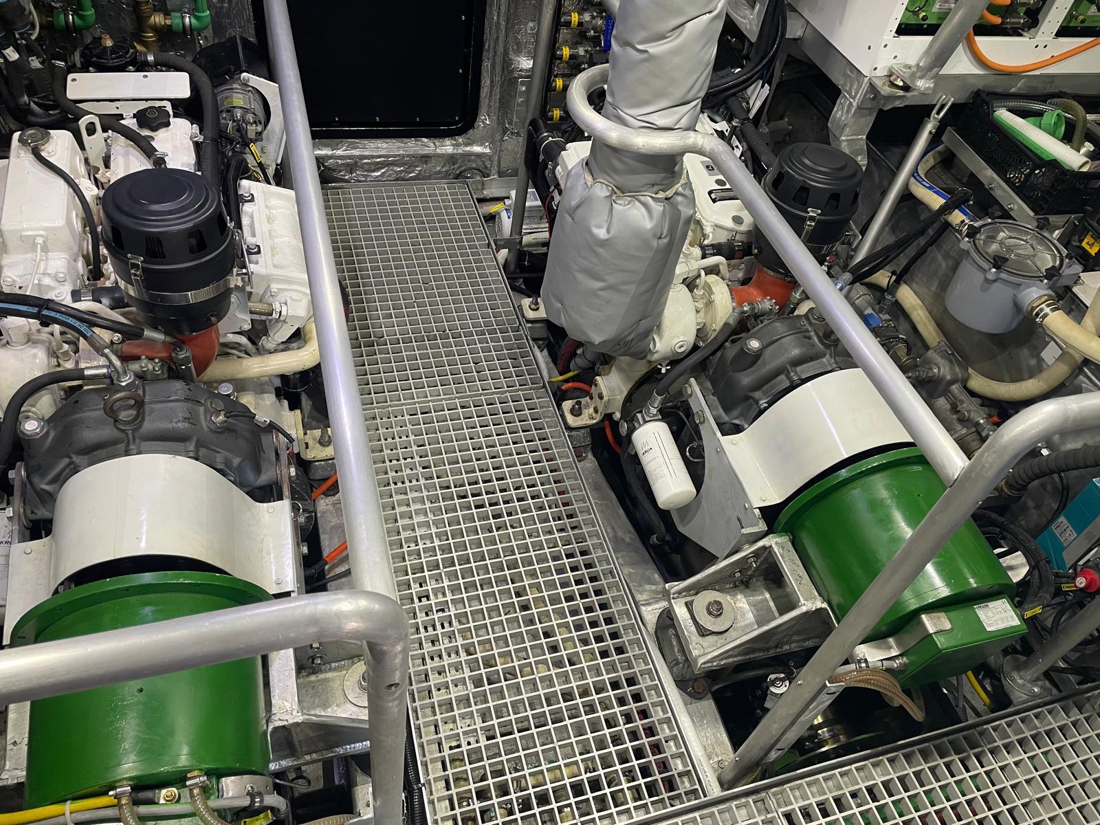
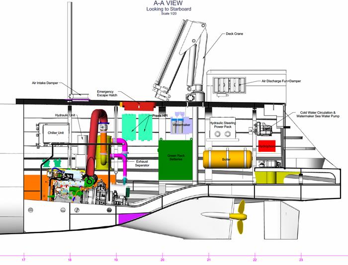
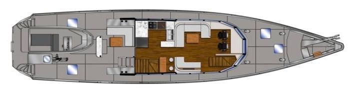
8.5 ENGINE ROOM LAYOUT
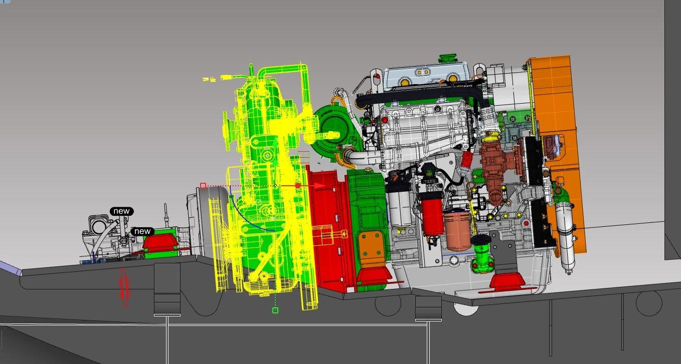
Major Engine Room equipment placement is as indicated in the above drawing. The Engine Room is designed for redundancy as demanded by the design mission.
Major elements of the engine room layout include:
• Two independent drive lines are installed each capable of full propulsion at sea.
• Rudders are duplicated and of substanMal construcMon resistant to impact damage.
• Propellers uMlize sail drives with feathering blades. They are installed in ice protected parMal tunnels.
• Electrical power is provided by two independent 60kW.H Power Ba^eries and three independent 7kW.H House Ba^eries
• Engine starter ba^eries are also independent and fi^ed with a power cross over in the event of failure.
• Two full flow sea sucMon filters are fi^ed and can be maintained with the engines in operaMon.
• All mission criMcal systems such as FW/Glycol, heaMng, fuel oil filters …. are duplex.
• Control and reporMng use commercial PLC based infrastructure from Praxis AutomaMon with a fully redundant Ethernet data backbone.
• House electrical is provides via 3 Victron MulMplus inverters charging 3 7kWH house ba^eries. A n emergency changeover allows powering of the three phase bus bars independent of the MulMplus controllers in the event of a single failure.
• All through hull penetraMons can be cleaned at sea and underway.
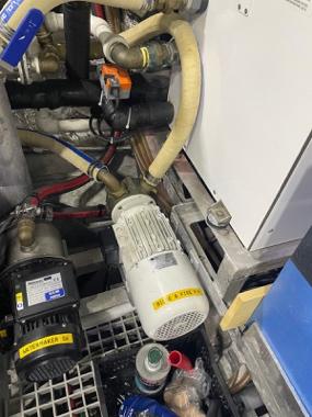
8.6 BILGE & FIRE PUMPING SYSTEM
The bilge pumping sytem onboard the VANGUARD consists of :
• One large bilge / fire pump in the Engine Room. This is a typical centralised system for a commercial vessel.
• A manual bilge pump accesed via the main deck, af of the Muster StaMon
• A number of electrically operated small condensate pumps providing secondary bile backup.
• Each bilge sucMon is fi^ed with a strainer.
• The main bilge pump sucMon is fi^ed with an addiMonal strainer to prevent damage to a criMcal pump and provide operator feedback on what is being pumped.
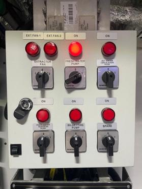
8.6.1 Electrical Bilge & Fire pumping system
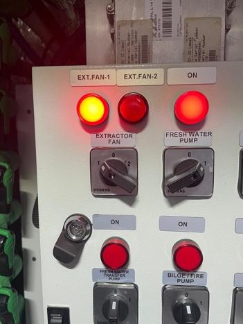
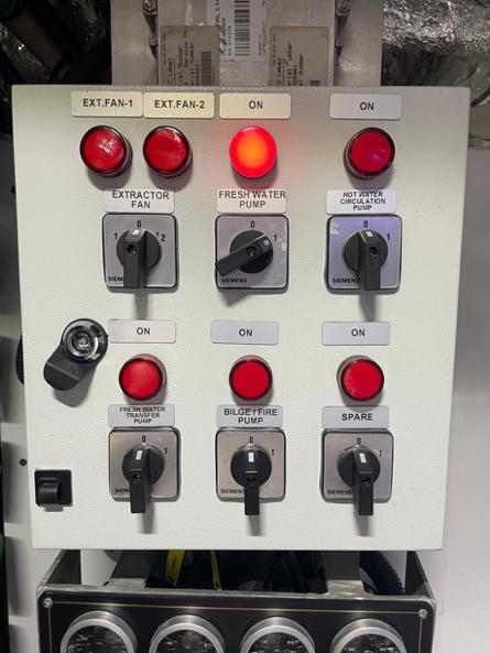
• The electrical fire/bilge pumps are in the Engine Room
• The pump is operated from the switch panel above the Stbd engine control panel.
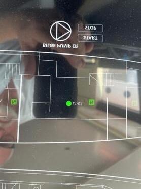
• The bilge pump can also be operated at the SAFETY MIMIC Panel on either helm staMon.
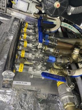
• The bilge manifold is located against the forward engine room bulkhead, Starboard side.
• The manifold is lef on Engine Room access sezng when not in use.
• The bilge/fire pump sucMon is fi^ed with a large sucMon strainer box to catch debris and protect the pump.
8.6.2 Emergency Fire Pump
The Bilge pump can be turned to Fire pump by:
• opening the FIRE MAIN V/V at the manifold
• closing the OVERBOARD V/V at the Stbd Engine Room overboard discharge
• Lay out the hose and open the hydrant.
• Turn the pump on at the pump control panel above the Stbd engine.
8.6.3 Emergency Manual Bilge Pump
The Emergency Bile Pump is operated from the main deck, af of the Muster StaMon.
• The handle is stored in the Fire Locker at the Muster StaMon.
• The system is self-contained and does not need preparaMon.
• It is used to evacuate only the Engine Room bilge.
Warning: Check function of all bilge pumps at regular intervals. Clear pump inlets of debris.
Warning: The combined capacity of the bilge pumping system is not intended to act as a high capacity Salvage pump.
8.7 FUEL SYSTEM
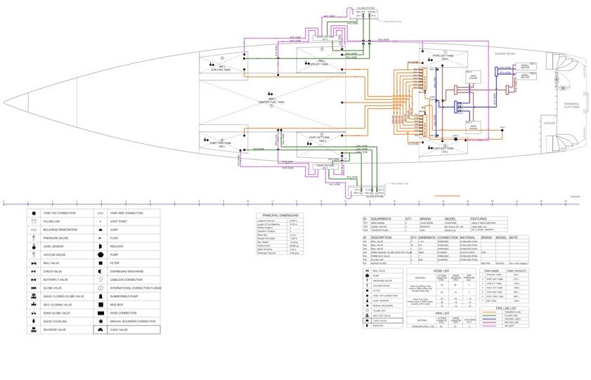
VANGUARD’s Fuel System is as illustrated in the enclosed drawing. General points to note are:
• Fuel is bunkered directly into the tank from the Port or Sbd bunker staMon.
o Tanks are fi^ed with a drain to deck for clearing rain water, this should be sealed when bunkering.
o They are also fi^ed with a drain to tanks for overflow, this should be opened during bunkering.
• Overflow is passed back down to individual tanks via the air breathers. Tanks are fi^ed with backflow preventers each with a small hole to allow for overflow drainage in Mme.
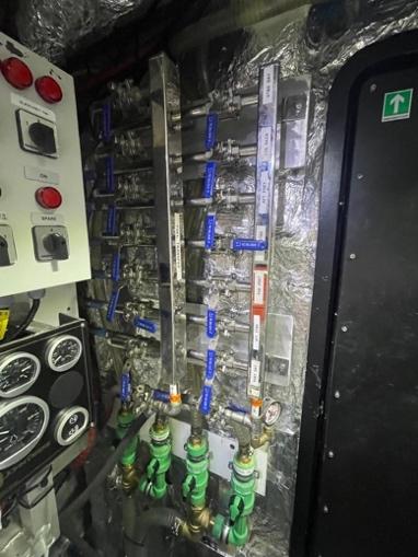
• Fuel transfer manifold is in the Engine Room, Fwd Port bulkhead.
• Fuel transfer pump switch is on the Port pump switch panel, above the port engine controls.
• There is a spare fuel oil transfer pump in the af locker Fwd of the af cabin toilet.
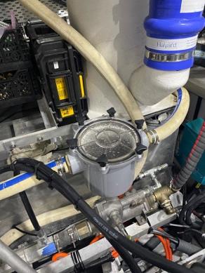
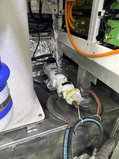
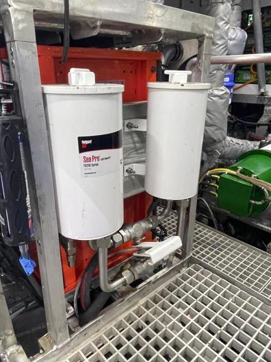
• All fuel transfers pass through a high-capacity Cummins Fleetguard SeaPro commercial duplex fuel filter that cleans fuel to John Deere engine fuel system inlet specificaMons of 3 micron and checks for water contaminaMon
• Fuel cannot be transferred without passing through this filter. The filter is located at the engine room work bench.
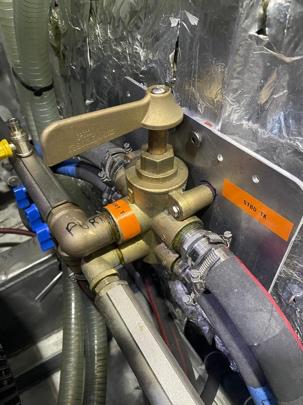
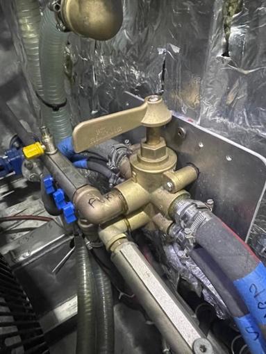
• Fuel flow and return to each of two-day tanks is controlled by a two posiMon 6-way valve by the fuel manifold. A simple 90-degree turn will change both supply and return flow.
• Webasto fuel heater and return are supplied via a fuel manifold at the same locaMon as the Day Tank fuel valve – see also secMon on HVAC.


Do not refuel while the engine is running!
Do not smoke during refuelling!
The filling staMon is only suitable for gravity filling.
Not all of the fuel tank capacity should be used due to the trim and loading of the vessel. A 20% reserve should be kept.
Regularly check for fuel leakage, do not damage the fuel lines. Avoid contact of flammable materials with hot engine parts. Only operate the emergency fuel shut off in case of an emergency as this valve will shut off the engines.
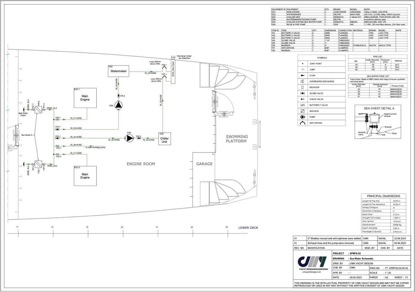
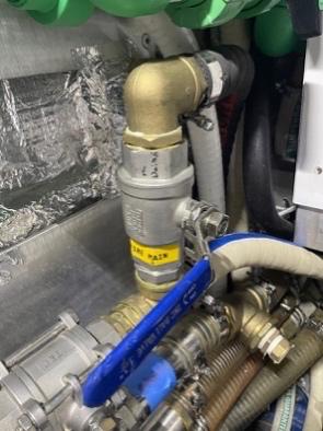
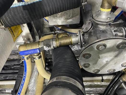
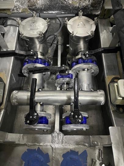
VANGUARD is equipped with a duplex sea water sucMon filter. Each filter is sufficient to operate two engines and all ancillary systems. Filters are equipped with bu^erfly valves so they can be cleaned at sea, underway and without shuzng down the engines.
• Sea water distribuMon system is illustrated in the first drawing above.
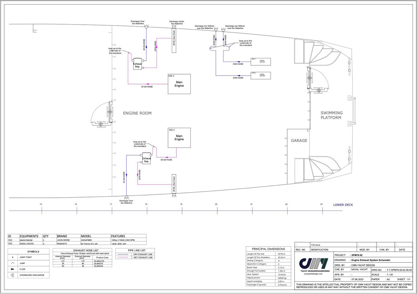
• Main engine sea water cooling system is illustrated in the second drawing above.
• All sea water is discharged via two overboard manifolds situated on the P & S side of the engine room. These manifolds remain above sea level and can be maintained at sea.
The seawater pump provides the external cooling system of each engine. The pump draws in water through the seawater intake (and water strainer). The water flows through the lines to the intercooler, engine oil cooler and heat exchanger.
Finally, the water is pumped into the exhaust pipe elbow, where it is mixed with the exhaust gases. Afer passing the water lock and gooseneck, the exhaust gasses and water will leave the ship above the waterline.
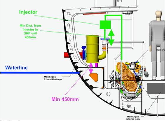
Before starMng the engine, open the seacock seawater intake for the water supply to the engine (in the engine room, front side of the engine).
CauVon!
• The VANGUARD is equipped a water-cooled exhaust. Always open the seacock seawater intake for water supply to the engine for a correct cooling of the exhaust system and the engine to prevent too high temperatures, which could lead to disastrous consequences.
• The water strainer should be inspected frequently and cleaned out when polluted.
• Afer starMng the engine, you must control if there is water flowing out of the engine exhaust opening at the transom.
www.
8.9 VENTILATION SYSTEMS
Cabins are provided with inlet and extracMon venMllaMon according to the following schedule:
Loca-on Level Descrip-on
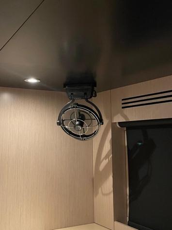
Saloon Main Deck - Two 6” fans drawing air from under the flybridge FWD sea>ng - One circula>on fan at the Hel sta>on. - Various automa>c temperature control fans for Praxis Control cabinets.
Fwd Cabin Lower Deck - Inlet fan drawing air from under main helm sta>on. - Two circula>on fans - One 4” extractor fan in the toilet
Mid Cabin Lower Deck - Inlet fan drawing air from the Stbd a^ saloon. - Two circula>on fans - One 4” extractor fan in the toilet
AF Cabin Lower Deck - Inlet fan drawing air from under the rear saloon access way.
- Two circula>on fans - One 4” extractor fan in the toilet
Engine Room Cabin Lower Deck - Two forced dra^ extractor fans with fire damper. - Inlet through single passive opening with fire damper
Galley Main Deck - one galley extractor hood operated by pulling open.
Note – saloon air inlets are fi^ed with passive mist eliminators and located high in the structure protected from the weather.
Note – the cabins draw pre -ondiMoned air from the saloon. This faciltates more effecMve HVAC performance as the water is humidity is pre controlled by the saloon HVAC when acMve.
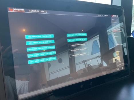

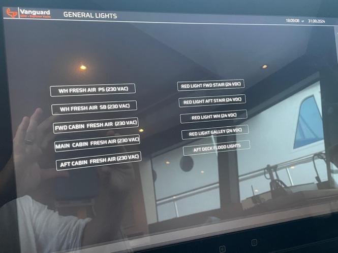
VenMlaMon fans are controlled via the MIMIC display, <LIGHTING / GEN LIGHTS> THIS MUST BE RESET IN THE EVENT OF A BLACKOUT.
8.9.1 GALLEY HOOD VENTILLATION
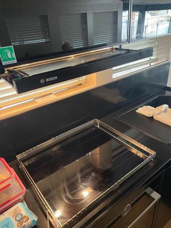
You can switch the galley extractor hood ON/OFF at the galley by pulling it OPEN/CLOSED. Kitchen hood exhausts on the Port Side roof of the saloon.
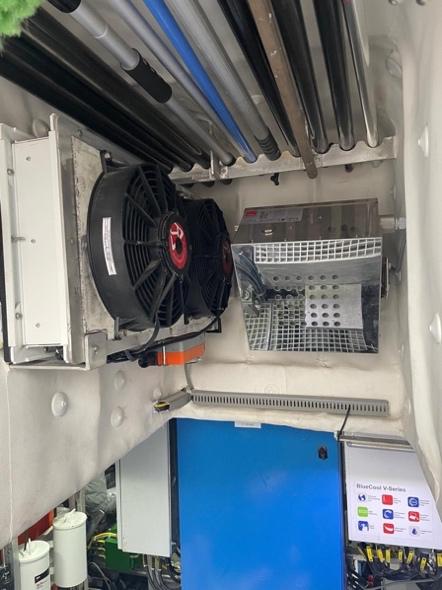
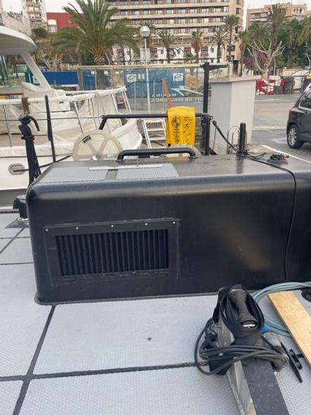
8.9.2 ENGINE ROOM VENTILLATION
• Engine room venMlaMon is controlled by two Delta T 11” axial forced draf extractor fans located in the af engine room access.
• Air outlet is at the rear Engine Room access.
• Air inlet is via the Muster StaMon structure.
• Both inlet and outlet are fi^ed with 12” fire dampers actuated from the Muster StaMon Fire & Emergency Stop panel.
• Fans are controlled via the switch panel above the Stbd engine controls.
• One fan can be used to supply air to both engines. Use two fans to limit the local air temperature.
Note - Extractor fans are not effecMve when the rear engine room access is open.
Note – In the event of emergency, engines can operate without ER extractor fans. In this instance, the rear engine room access and engine room hatch should be open and monitored.
8.10 FRESH WATER SYSTEM
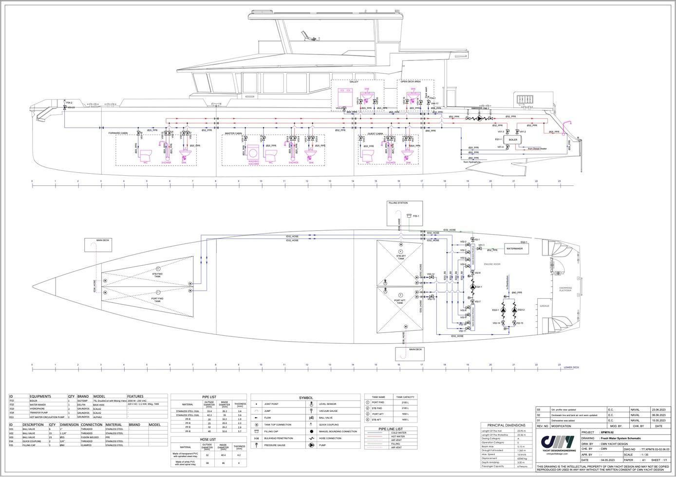
The freshwater system consists of 4 water tanks that act as storage but also ballast compensaMon to maintain trim and stability as fuel is consumed. Water is provided either from shore or via a Water maker located in the af engine room, starboard side.
• Water is distributed through a manifold on the Fwd engine room bulkhead, Stbd side.
• A transfer pump is located under the manifold and operated from the pump switch panel in the same locaMon. Transfer pumps can draw and deliver to any of the 4 tanks.
• Two Grundfos Scala pumps provide a constant water pressure. These pumps draw from the Af Stbd or Port Tanks. Water pressure gauge is by the af engine room access. These pumps are speed controlled for a constant delivery pressure and should not run dry. In the event they do then the Transfer pump can be used in creaMng a sucMon flow to assist in priming. The outlet should be vented via the af shower or af cabin bathroom to also assist.
CauVon!
• Try not to let the freshwater tank run dry. If this happens you will have to transfer addiMonal water to this tank and then prime the sucMon pumps.
• Check water filters on inlet and outlet of the water maker and under the galley sink and replace regularly as per the manual.
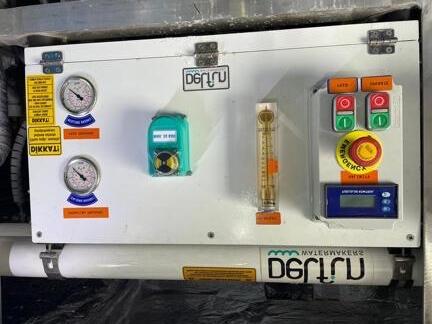
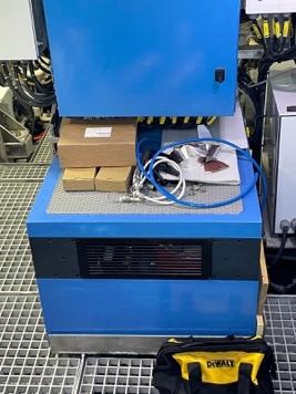
8.11 WATERMAKER SYSTEM
A 7L/m Delfin water maker is located at the af engine room access. Water should not be produced within 3 NM of land and never in Marina. The Delfin water maker is situated in the Stbd Af engine room by the steering gear.
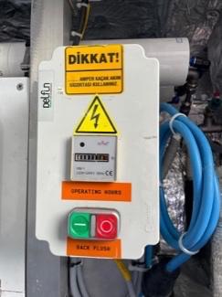
• Replace pump oil afer the first 50 thereafer 300 hours of operaMon 10W/40 oil.
• Chack and replace discharge filters and back flush filter at regular intervals as pe the operaMng manual.
Preparing the system
• Open the <SEA COCK> located between the engines by the sea water sucMon manifold.
• Open the water maker inlet valve on the freshwater manifold.
• Open the tank that needs filling.
• The sea water overboard valve is permanently open.
StarVng the water maker
• Start the <FEED PRESSURE> pump (approx. 4 bar) this will show that water is flowing through the equipment
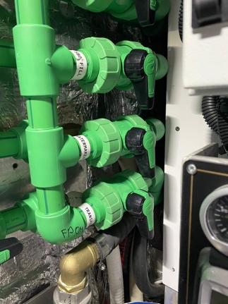
• Start the <OPERATING PRESSURE> pump. This will run for about 2 minutes to create the max 55 bar OsmoMc Pressure before the unit will start making water.
• The salinity is monitored on the <SALINITY> meter and should remain between 200 to 500 ppm. A high salinity value is an indicaMon of failure of the purificaMon membrane.
• FW output flow should remain around 1.4GPM / 5.5l/min. If falling below, then replace the 5- and 25-micron water filters on the front of the unit.
Stopping the water maker
• Stop the <OPERATING PRESSURE> pump, Stop the <FEED PRESSURE> pump
• Start the <BACKFLUSH> pump. This will cycle automaMcally and then shut down.
• Close the inlet and FW tank manifold valves.
CauVon!
• Do not use the water maker less than 3NM from land or in Marina’s.
• Check filters on inlet and outlet and replace regularly as per the manual.
• Cut operaMon if salinity rises above 600ppm when in operaMon.
A separate manual for the watermaker is provided with the boat. Please read this manual carefully.
8.12 GREY WATER SYSTEM
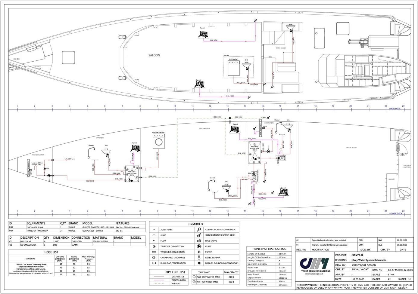
Grey water consists of sink, shower, washing machine and dishwasher water. Within the EU laws it is allowed to drain this water overboard. Although you should always check the local authority regulaMons against marine polluMon and respect these as much as possible.
Grey water should be treated regularly (weekly) by adding biocide agent to each sink and shower drain. This will assist greatly in minimising odour and maintaining a healthy system.
CauVon!
Do not discharge grey water in restricted areas of environmental sensiMvity.
Check grey water tank levels before operaMng Washing Machine or Dishwasher.
Overflowing grey water tank will spill via the shower drains and trigger a bilge alarm.
Use mild cleaning detergents as not to damage the rubber parts in toilets and pumps
8.13 BLACK WATER SYSTEM

Toilet units on VANGUARD are macerator types. They will handle human waste and toilet Mssue paper only.
DO NOT use toilets for discharge of any other materials such as co3on buds, wet wipes or sanitary towels. In case of blockage, those responsible will be unceremoniously keel hauled in front of their crying heirs and their remaining, possibly live carcass, deposited on the nearest uncharted rock, regardless of provisions or weather.
AddiMonally, toilets are fi^ed with a Bidet unit to minimize the use of toilet Mssue as its availability is ofen in short supply. Please use it, even when in arcMc waters. In pain you may seek redempJon!
Black water should be treated regularly by adding biocide agent to each sink and shower drain. This will assist greatly in minimising odour and maintaining a healthy system.
The black water tanks should be cleaned on a regular basis by flushing water through the “waste” deck pump out sucMon fizng to prevent waste build up from blocking the lines.
CauVon!
• Do not discharge the black water tank close to shore or in any prohibited zone.
• Use marina pump-out faciliMes to empty the holding tank when in harbor.
• Use mild cleaning detergents as not to damage the rubber parts in toilets and pumps
8.14 GLYCOL COOLING SYSTEM
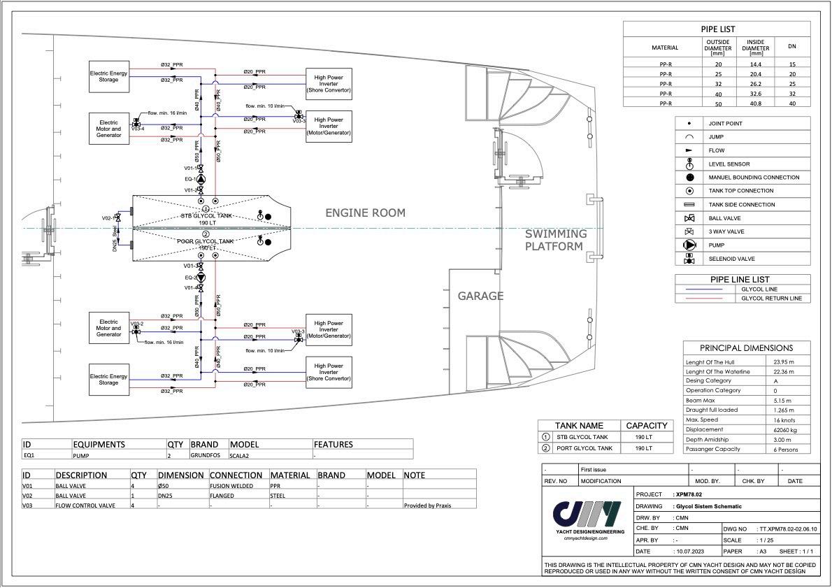
VANGUARD is a diesel electric hybrid yacht. Her systems are designed to handle large amounts of power for storage or propulsion purposes. This 600VDC electrical power is handled by generators, ba^eries and inverters and each of these is temperature controlled from a single water/glycol cooling system.
• The storage tank is located between the engines. It is keel cooled against the flow of sea water underneath.
• Glycol flow is provided by one of two Grundfoss Scala pressure-controlled supply pumps located between the engines, Engine Room Af.
• Flow is distributed through manifolds located at the pumps and on the forward Engine Room bulkhead.
• One pump is required to control operaMons above a power consumpMon of approximately 1,500W as displayed on the Victron Cerbo display on the Main Helm StaMon. It cools the Praxis inverter, HPI 4.
• Large Power Ba^eries control their own flow, HPI (Praxis Inverters) and Motor/Generator flow is controlled by selecMon of piping sizes.
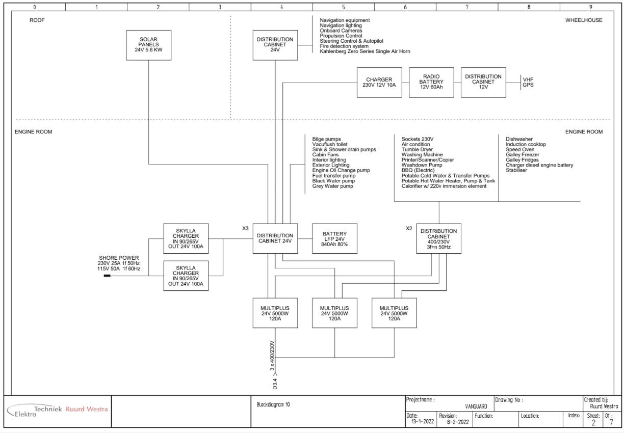
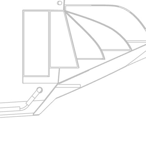
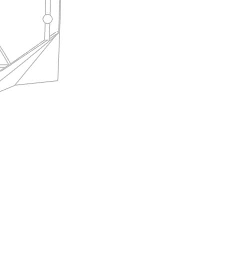
8.15 SOLAR SYSTEM
VANGUARD is equipped with a 6.0kW solar array situated on the three upper cabin roof surfaces. Shading will significantly reduce this figure, it alters during the day. A small amount of shade will reduce the performance of a panel to zero.
Panels are monocrystalline PV cells on a flexible backing. They are glued to the substrate with the PV connecMons being on the rear face. Each panel is equipped with bypass diodes meaning that the panel can be bypassed when shaded. This preserves the funcMon of the remaining panels when connected in series. (Note: panels under life rafs were fi^ed in error and are disconnected.)

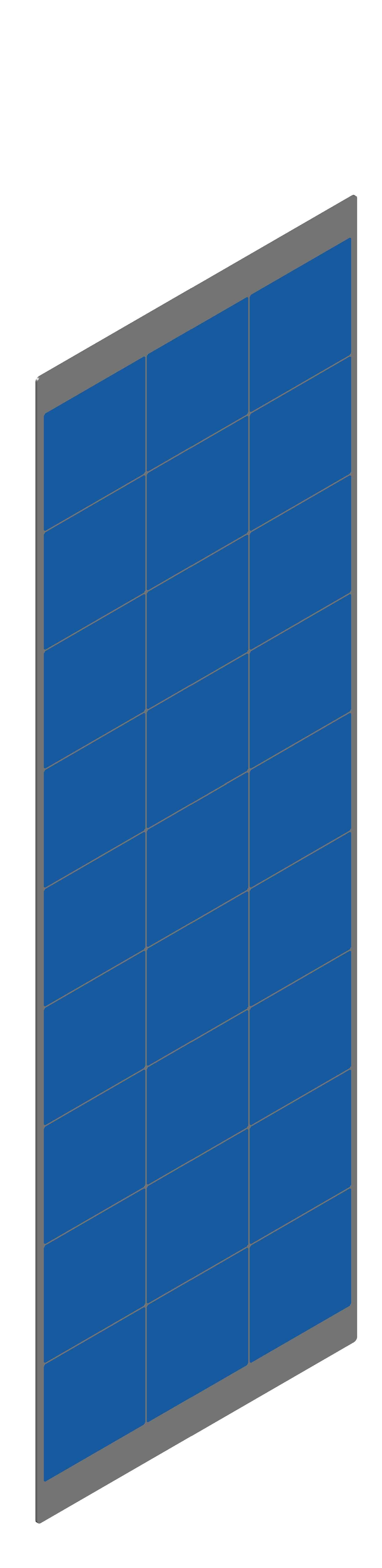

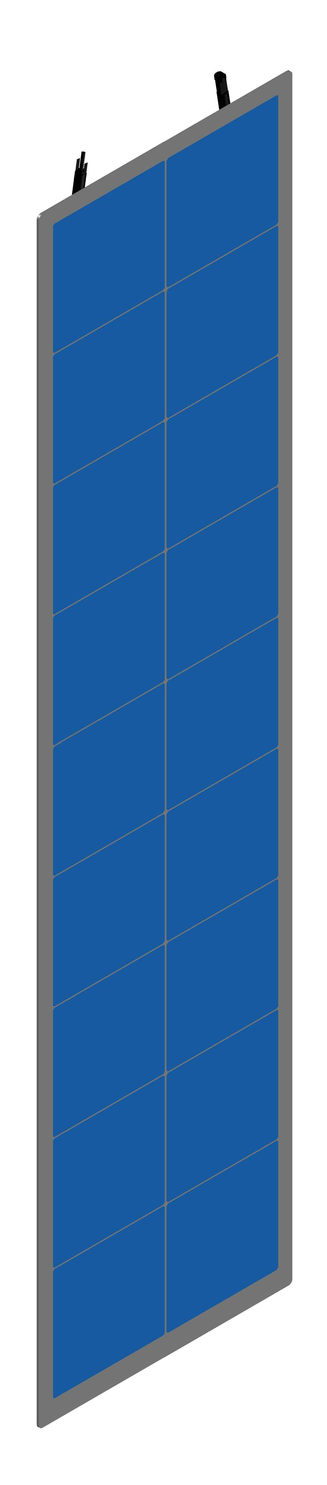

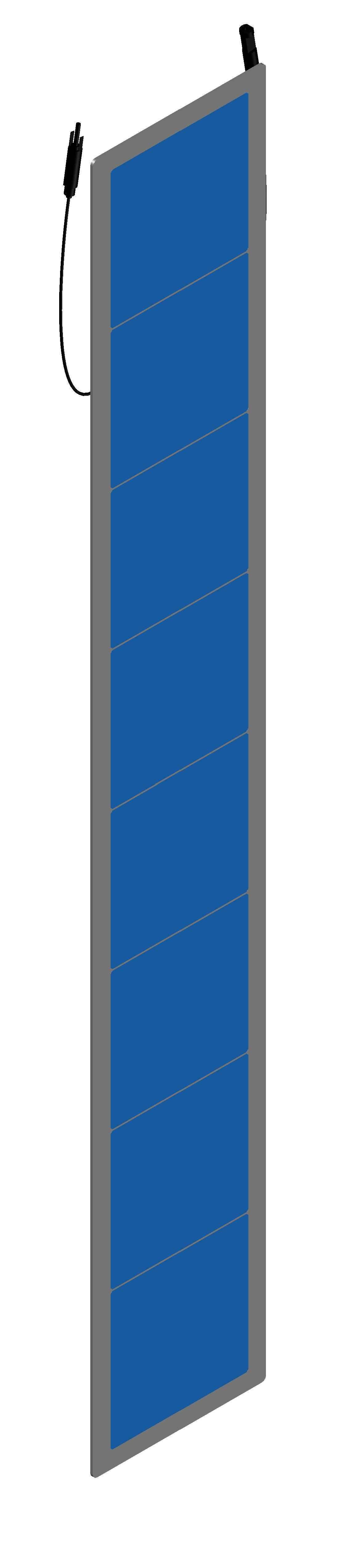

They are connected at X3, the DC DistribuMon panel in the Engine Room, Stbd Af. X3 also houses the Victron MPPT controllers used to conMnuously charge the 24VDC House Ba^eries.
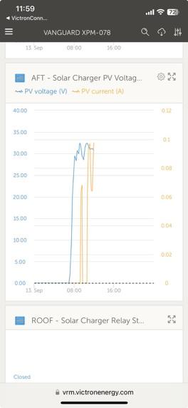
Control is via the Victron Cerbo GX system. Custom sofware has been installed to ensure that Solar power is used in preference to Shore Power or Praxis Power Ba^eries. This is achieved by different charge trigger sezngs with the “grid” used when House Ba^ery charge falls below X% (typically 80 but can be varied). Solar charg at 98% and below. Solar performance can be monitored both from the Cerbo and “VE Connect” app on a laptop or the “Victron VRM Portal” for a mobile device.


Warning : PV panels will be live when the sun is shining, voltages can rise to <250VDC. They should be disconnected before working on the system in any way.
www.Exploreryacht.com for the journey. Page 44 of 102
Customer : Chris Leigh-Jones
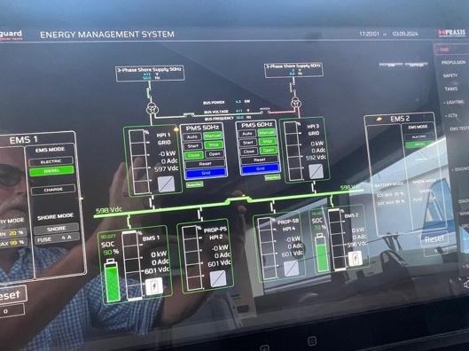
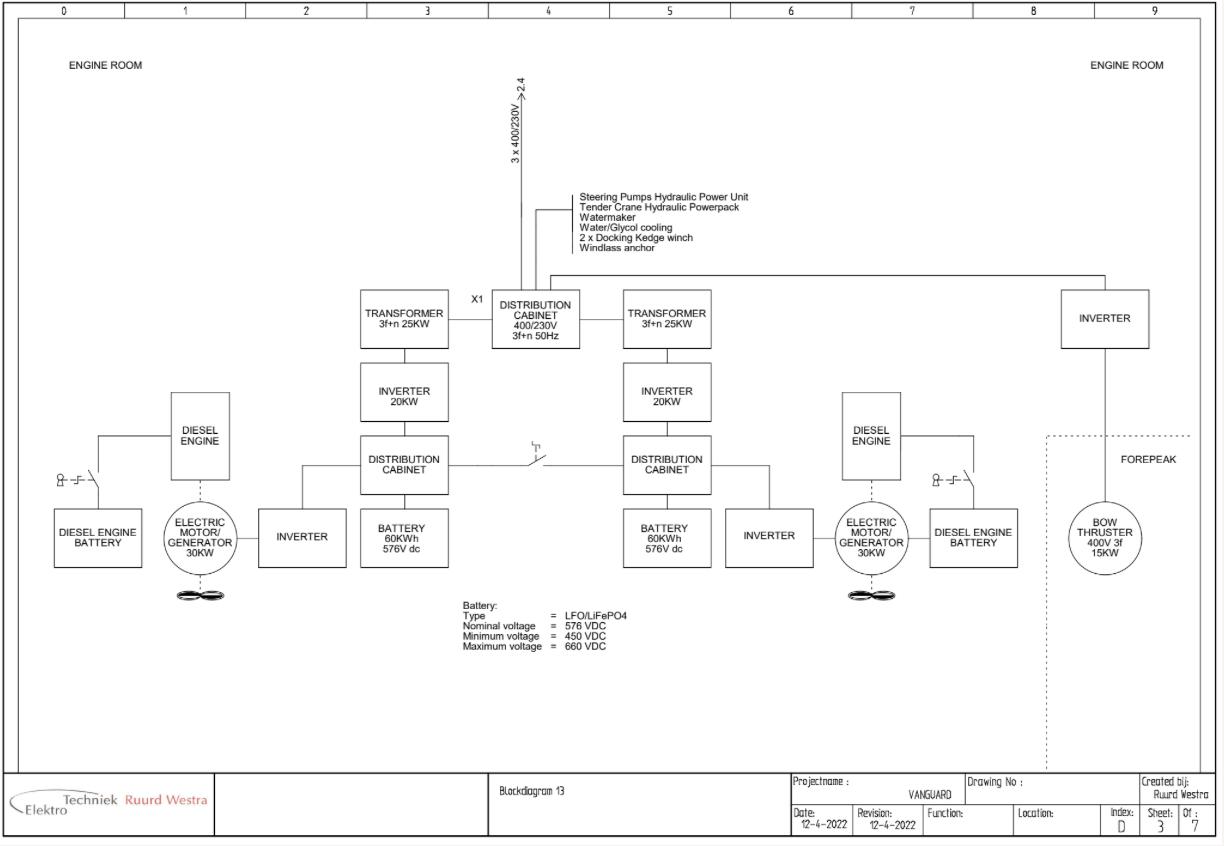
8.16 PRAXIS HYBRID PROPULSION AND POWER MANAGEMENT SYSTEM
8.16.1 HYBRID ELECTRICAL SYSTEM
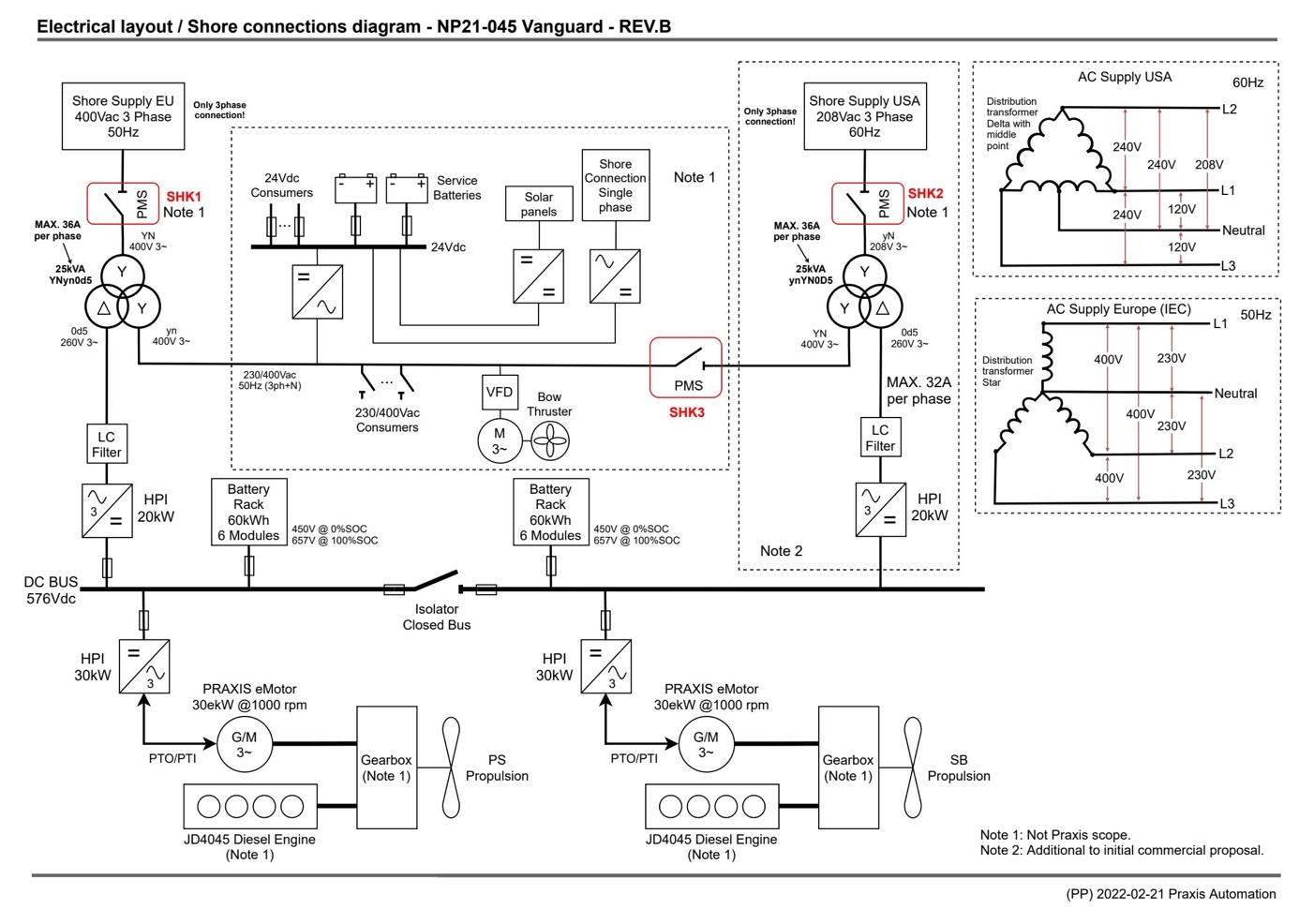
An overview of the electrical system is shown above. The system is based on commercial pracMce for parallel hybrid diesel electric operaMon. Key features are:
• Propulsion from duplicated parallel hybrid drive lines. 112kW Diesel propulsion, 30kw Electrical Propulsion and 36kW GeneraMng capacity, duplicated.
• Power storage from 2 x 60kW.H 600VDC power ba^eries and 3 x 7kW.H 24VDC house ba^eries. All LiPO and monitored, house ba^ery charging is restricted in sofware to 2kW each max to comply with the sMpulaMons of MGN280.
• Shore power from 50 or 60Hz, three or single-phase giving total worldwide compaMbility.
• Solar from 6.5kW in stalled array producing 1.5-2.5kW weather and shade dependant.
• 100% redundancy of all criMcal system.
• House electrical system via Victron integraMon with Cerbo Controller.
Warning:
• Disconnect shore-power connecMons when the system is not in use and una^endend.
• Use double insulated or grounded (earthed) electrical appliances.
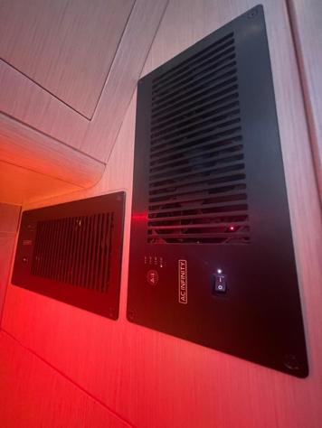
• Do not obstruct PRAXIS POWER BATTERY venVlaVon ducts.
• Do not allow the shore-power cable end to hang in the water. An electrical field can be caused which can cause injury or death to nearby swimmer.
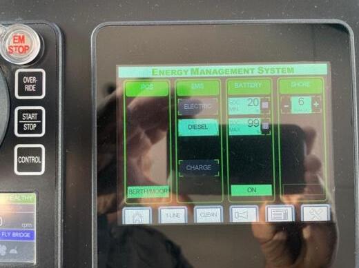
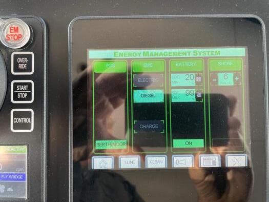
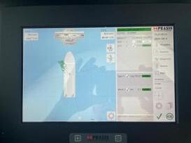
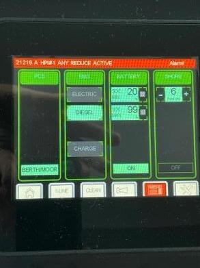
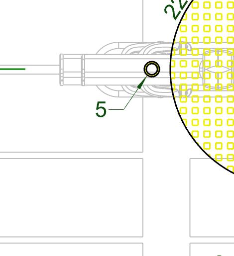
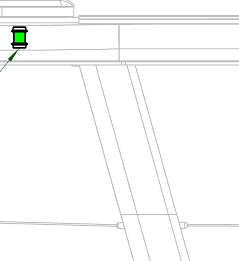
8.16.2 Connec:ng The Power BaXeries
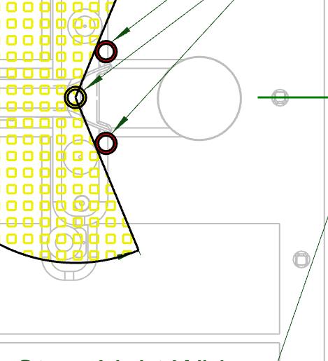
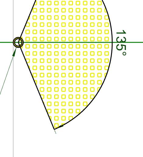
On the a^ached illustraMon, the EMS is showing a white line in the red circle indicaMng Power Ba^eries are NOT connected.
Power Ba^eries can be connected when the DC Bus Bar voltage is <50VDC. If DC Bus Bar is >50VDC you first have to drop this voltage to <50VDC before connecMon.
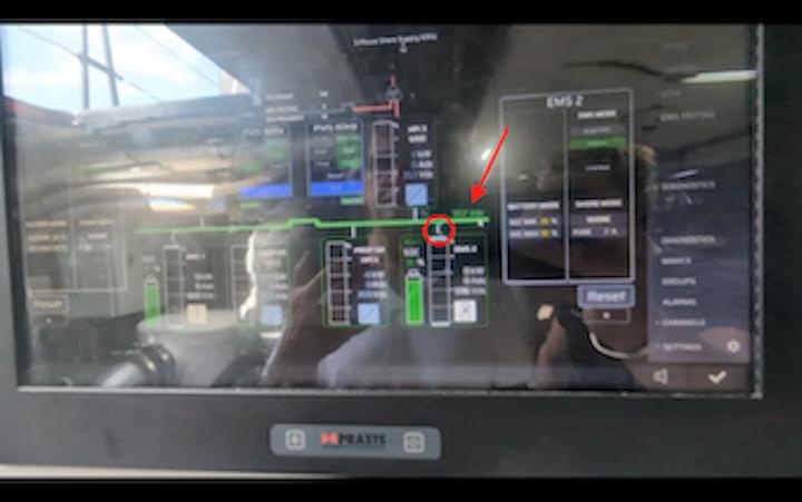
• Disconnect the three-phase shore power in the SHORE POWER CABINET. The voltage will slowly drop on the DC bus bar as energy dissipates.
• When voltage drops <50 VDC, open the pop-up window for the ba^eries by tapping on the ba^ery image.
• The contactor will read <OFF> if the ba^ery is not connected.
• Press the framed <OPEN/CLOSE> to connect the ba^eries.
• Repeat for both ba^eries. There is some delay in the operaMon as the ba^eries slowly come online.
• When connected it becomes green and, (the DC bus bar in the image shows 357 VDC)
• If PMS module of the screen is RED, Press the RESET bu^on.
• Press the “Ready to Start”.
• Make sure the PMS module is in “Auto” mode.

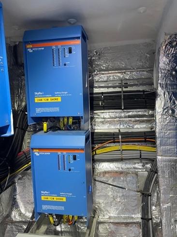
8.16.3 Shore Power Connec:on
Single Phase - 120/240 VAC 50/60 Hz
• Single-phase shore-power is connected to Victron Skyle isolaMon transformers
• The IsolaMon Transformers are located Port side of the steering plaÅorm
• Output is delivered to the house ba^eries at 24VDC.
Shore power will handle 50 or 60Hz 120 – 240VAC even with reverse polarity! The Victron Skyla inverters also act as galvanic isolaMon transformers to protect the aluminium hull from electrolyMc damage. Power is converted to 24VDC and dropped to the house ba^eries.
• Connect shore-power cable
• Turn on both Victron Skyla inverter chargers located in the af Port Engine Room
• Adjust the maximum charge current on the charge controller. VMS panel under the MIMIC screen in the Engine Room.
• charge current.

Three Phase – 240 – 480VAC 50/60HZ
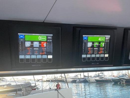
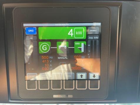
Shore power is connected to the Praxis 25KVA three-phase isolaMon transformers, midships on the steering plaÅorm. Shore power is controlled by 1 or 2 Praxis Power Management Systems (PMS) at the main helm staMon and repeated at the MIMIC displays on the helm and engine room. Voltages may dip due to local supply capacity. The system is automated.
240/480 VAC 60Hz
• This is USA & Canada and parts for South America plus Japan.
• Power is supplied to the 600VDC power ba^eries and isolated from all other ship systems.
• 390/415 VAC 50Hz (approx.)
• This is the ROW shore supply frequency and voltage.
• Power is supplied to the three phase bus bars, L1, L2, L3

ConnecVon of three-phase shore supply - Plug and play!
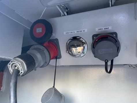
Three-phase is connected via the shore power sockets in the af locker. One socket for 50Hz and one for 60Hz supplies. 50Hz is fed to VANGUARD’s mail three-phase distribuMon. 60Hz is converted to DC and used to charge the power ba^eries. The system uses 2 large 25KVA (20kW) isolaMon transformer to protect the aluminium hull.
• Connect shore power cable
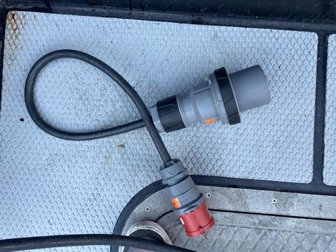
• The Praxis Power Management system is located at the main helm, upper Port side, one for 50, one for 60Hz supplies. Occasionally the local phase rotaMon will be opposite to that of VANGUARD. This will set an alarm on the PMS and prevent closure of the breaker. Use the short shore power bobbin piece to reverse the phase and allow full connecMon.
• Set the maximum shore power current at the EMS on the main helm. Typically, this is 46Amps
• One single line MIMIC, set the shore power to “AutomaMc”.
• Prime the shore power breaker and press “Connect” shore power will now be connected to the ships systems via the AC Bus Bars in Cabinet X2
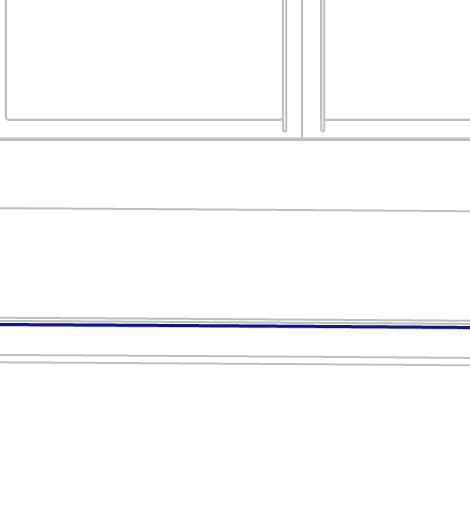
• The single line MIMIC will show “GRID” in blue, this can be changed to “CHARGE” in green if there is need to charge the power ba^eries from shore and sufficient capacity available.


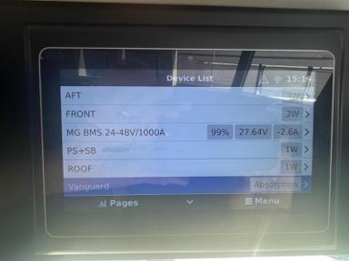
NOTE:
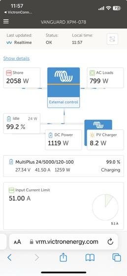
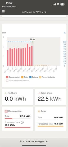
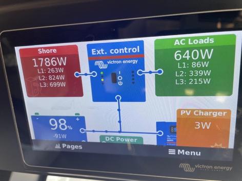
Shore power consumpMon is available on the Victron Cerbo display at the main helm staMon. This will show the draw on each phase L1, L2, L3 and DC 24V system plus the input from Solar and Shore Power (or Power Ba^eries). It is convinient informaMon allowing adjustment to HVAC, lighMng and parasiMc loads in order to minimise power consumpMon on VANGUARD
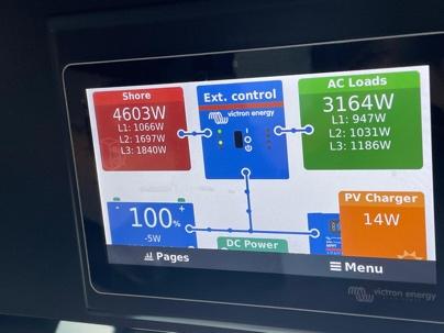
• The minimum is typically around 1.4kW with all system usage minimised, lights out in unoccupied rooms, uMliMes off, natural venMlaMon.
• A maximum experienced 10kW running HVAC, lighMng, charging house ba^eries and operaMng uMliMes. Power availability is large but not infinite!
Low Voltage Dropout
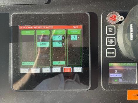
The PMS can be set to <MANUAL> to prevent drop out under fluctuaMng shore voltages. (Hard stop is 340VAC) On the EMS Single Line Diagram, set the HPI (1 & 2) to <MANUAL>
Switching Shore Power off when set up to resist Low Voltage Dropout
• In the Shore Power Cabinet, trigger the shore power breaker by pressing the <RESET> bu^on
• On the VMS Cabinet in the engine room, EMS, Single Line diagram: Change <MANUAL> to <AUTO> on HPI-1 and HPI-3, Change <CHARGE> to <GRID>
• Press the hard <RESET> bu^on for both PMS(1 & 2)
• This will connect the Power Ba^eries to the HPI and energise the AC Bus bars in Cabinet X2
• Proceed as normal independent of shore power.
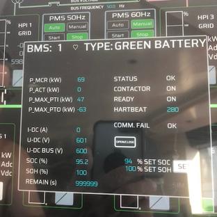
8.16.4 Charging Power BaXeries
2 by 60kW.H Praxis Green Ba^eries can be charged 3 ways.
1. From 3 phase shore power (they are typically too big for single phase).
2. From either engine when underway (not both).
3. From either engine when VANGUARD stopped
Charging from three phase shore power.
This is possible when the shore power load is below 2/3kW. Charging power ba^eries when uMliMes and HVAC is running will potenMally overload the system and cause the shore power to trip. Charging can be undertaken from HPI 1(50Hz) or HPI 3 (60Hz).
• Select maximum shore power amperage from the EMS staMon at the helm, typically this is set at 4A.
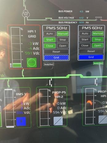
• On the Praxis EMS MIMIC, Single Line Diagram, set PMS to MANUAL
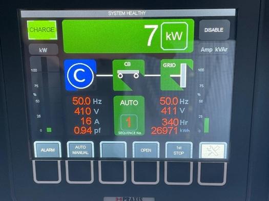
• Set GRID (blue) to CHARGE (Green), press START. Charge will change to Blue hashed GRID and the ba^ery charge indicator will also turn Blue.
• In the illustraMons above, the PMS indicates 4/5kW is being drawn from shore power. The Victron Cerbo indicated 1.8kW at the three phase bus bars and the EMS indicated 1kW is flowing into each of 2 power ba^eries. So 1+1+1.8 approximates to 4/5 showing where the energy is coming from and going to.
Charging when underway.
When engines are operaMng and you are underway, press CHARGE on the EMS by the thro^le controls. This will change to a green hashed light. Under these condiMons, the system will selfregulate, charging ba^eries and providing ample power for all services. It can be lef in this condiMon when underway.
Charging when vessel stopped.
This is nearly the same as charging when underway. The difference is that the drive is clutched manually at the Praxis/Local selector by the House Ba^eries. This will engage the clutch without moving the thro^les from neutral. Then conMnue as above. The charge power is set at 36kW (18 per ba^ery) and the engine speed at about 1600 RPM. The system will respond autonomously under this sezng and complete charging when ba^eries are full.
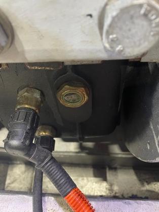
8.16.5 Electrical Earth Detec:on System
Vanguard vis an aluminium hull yacht. Aluminium is suscepMble to galvanic corrosion a result of either a shore power fault or an internal earth leakage. Earth leakage on Shore power on single and three phase connecMon is protected by IsolaMon Transformers. To protect from stray current circulaMon within the systems themselves (Earths), Vanguard is fi^ed with a detecMon system designed to monitor earth faults on:
• 24VDC bus bars, both lines
• Port engine and drive, both lines
• Stbd engine and drive, both lines
The earth detecMon system is situated above the port engine, af of the pump control panel.
• Each detecMon circuit is labelled.
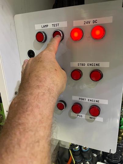
• Press <LAMP TEST> on each of the 4 systems to check it is in operaMon.
• Press <TEST> on each system and observe that the two circuit lamps are lit and of equal intensity. If they are not, then there is an earth present on that parMcular system.
Analysing an earth leak is a complex task and will require the support of a competent electrical technician. There is no immediate danger, but it will need correcMon.
www.
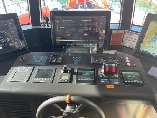
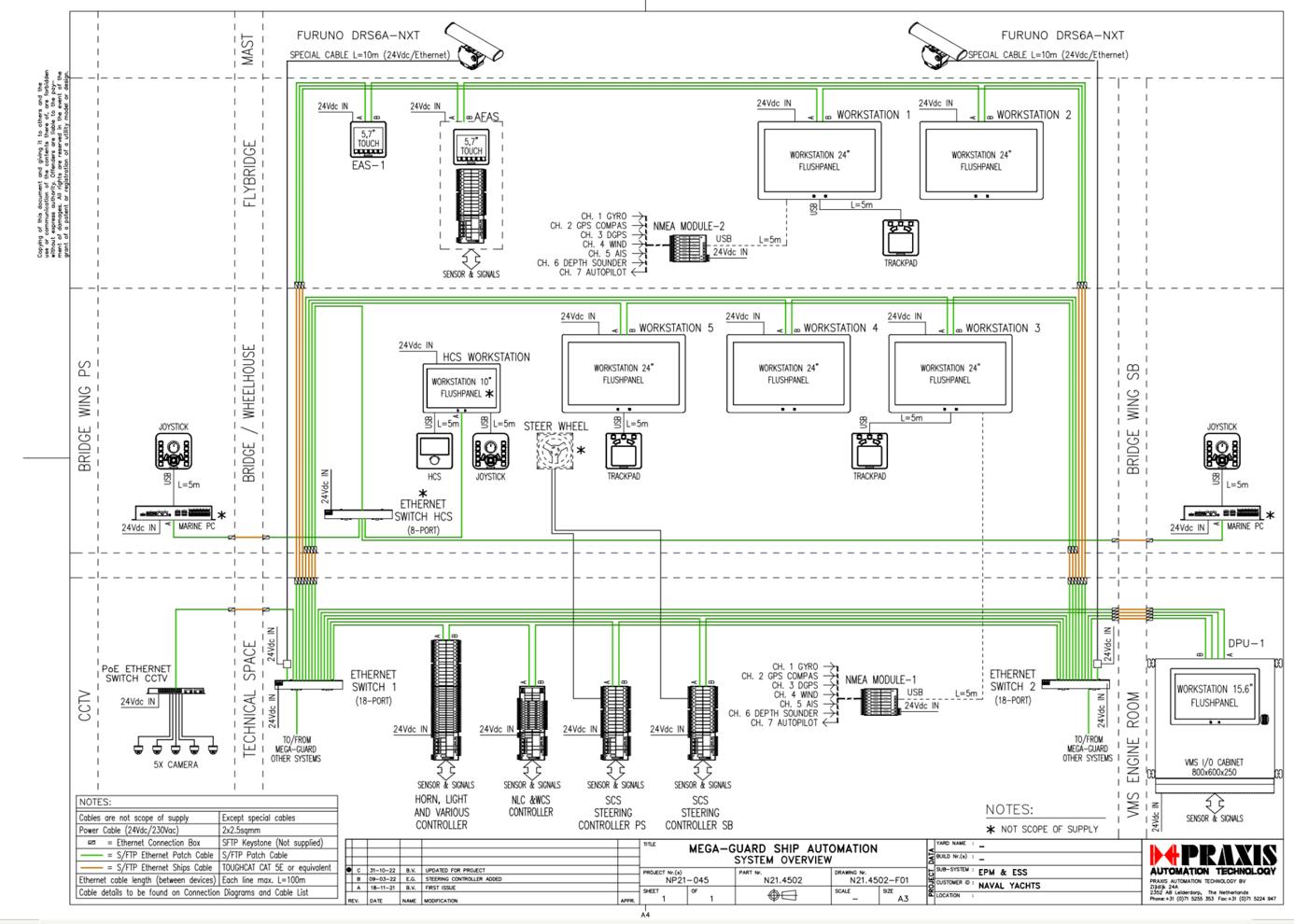
8.16.7 Praxis Integrated Power & Energy Management System. This is the heart of VANGUARD. It provides for monitoring, navigaMon and control funcMons throughout the vessel. Control is limited to a few discrete items such as steering, engines and navigaMon lights. For control of pumps and systems, it will be necessary to visit the Engine Room as appropriate.
The basic system is as illustrated below. WorkstaMons or MIMIC diagrams are presented on the Flybridge, main Helm and engine Room. Controllers or PLC are located at the Main Helm and Engine Room. CommunicaMon uses a fully redundant Ethernet backbone. System operaMng computers are located at each of two navigaMon screens on the main helm and again provide redundancy.
The NavigaMon uses Time Zero Professional V4 which also displays instrument data and Radar as required. Engineering data is reported on the third helm screen as well as the flybridge and engine room.
See other secMons within this manual for specific operaMng instrucMons. InformaMon is also available within the maintenance system specific to individual tasks that may be required from Mme to Mme. The operator is encouraged to use the screens and be^er understand just what is available and its funcMon.
www.Exploreryacht.com for the journey. Page 52 of 102
8.17 HVAC AIR CONDITIONING SYSTEM

HVAC uses the Webasto Blue Cool system for cooling and heaMng. The chiller unit is located Stbd side of the Engine Room, the system can also be shut down locally from this locaMon. Cooling water is drawn from the sea sucMon filters with its own dedicated pump. Chiller coolant is glycol based with its own circulaMon pump and accumulator. Maintain a circulaMon pressure above 1 bar. The pressure can be occasionally topped up with fresh water using the hose adapters provided.
HeaMng is provided by two Webasto diesel heaters located by the af engine room access. Fuel supply and return comes from the fuel manifold on the Fwd Port engine room bulkhead. These heaters act to heat the circulaMng glycol fluid when then passes to the various air handlers.
• Air is drawn from under the flybridge seaMng.
• Air enters the salon at the helm staMon.
• Two air handlers’ condiMon for temperature and humidity. These are located Port side behind seaMng, Stbd Side behind the galley storage.
• Air is drawn from the salon into each of three cabins. Each cabin has its own air handler and controls.
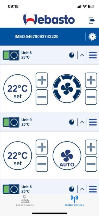
AddiMonally, the system can be controlled remotely using the Webasto Blue Cool Connect App on a smartphone.
NOTE: the HVAC can draw up to 5kW. Close blinds and cabin doors when in use to minimize energy consumpVon. Shut down system in unused spaces and where possible in the saloon during the day. To preserve bageries, always use natural venVlaVon in preference to HVAC. Shut the system off when in temperate climates.
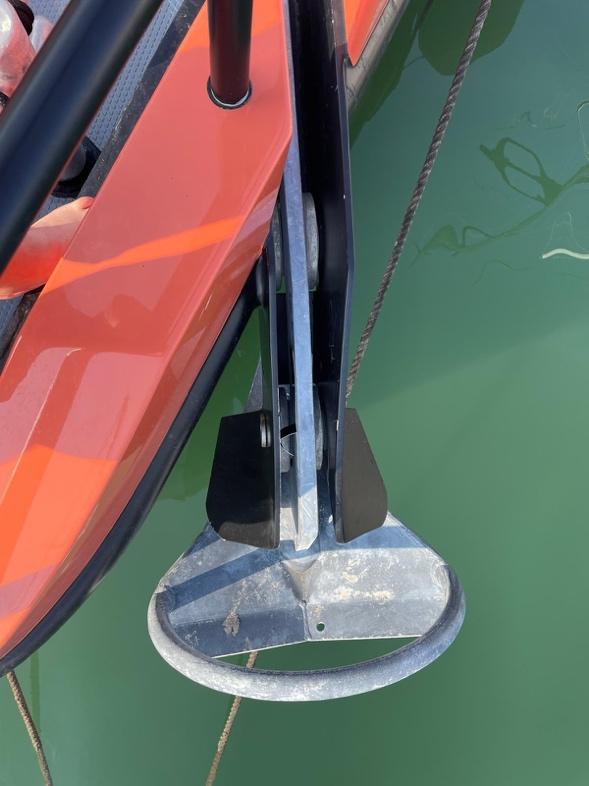
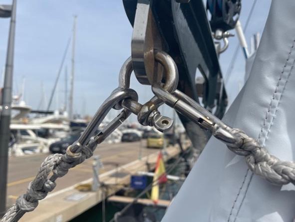
8.18 ANCHORING SYSTEM
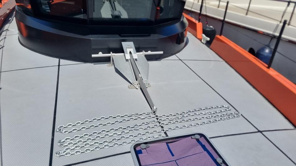
The main anchor for VANGUARD is a 110kg Rocna anchor. This is oversized for the applicaMon with typically recommends 60-70kG for a 24m vessel.
This anchor is fi^ed with a Mantus anchor swivel and 100m of 14mm Galvanized G40 chain. Chain is color coded as per the table below. The bi^er end is Med to a cross beam within the forepeak and provided with a local knife if release is necessary.
COLOR Scope Applica-on
Red 20m - Just about got the anchor wet.
Yellow 30m - Day anchoring most anchorages up to 5m depth
Blue 40m - Day anchoring most anchorages up to 10m dept
White 50m - Day anchoring most anchorages up to 15m dept
Green 60m - Overnight anchoring up to 10m depth
Uncoded 70-100m - Storm anchoring, consider also shorelines and kedge anchor
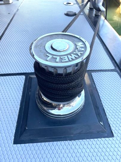
The anchor is worked by a Maxwell combined anchor windlass and capstan It also has an anchor chain stop and break.
The capstan can be disengaged from the windlass using the rotary clutch on the top. Once disengaged it can be used for warping lines with the windless drum being level with the hull edge for entry at the drum base.
The foredeck is arranged with a forward well that drains through the tow fairlead. This minimizes sludge and mud buildup when anchoring in glacial fields or estuaries.
To prevent difficult in stowing the anchor, it is fi^ed with a heavy-duty anchor swivel from Mantus.
Opinion is divided about anchor swivels. They represent a point of failure and for most cases are unnecessary. However, the anchor entry on VANGUARD is to the side and the anchor must stow in a single posiMon. Having a swivel greatly eases this process.
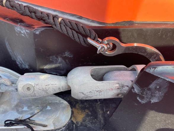
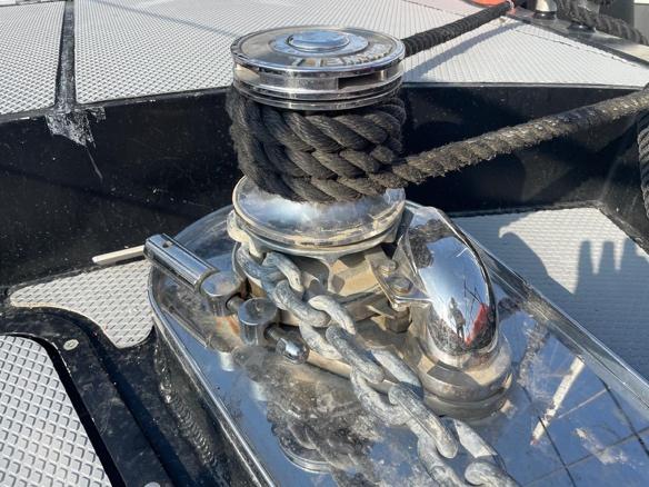
The chain is also retained when underway using Mantus anchor hook that can be hooked in at the swivel.
A kedging anchor is also fi^ed, 35kg Fortress anchor. It is located on the foredeck. 10m of 10mm G40 galvanized chain, suitable shackles and 100 feet of rode for this anchor are stored in the forepeak.
It can be removed by undoing eh 4 retaining bolts and reassembling. It is light enough to be easily carried for deployment in the tender.
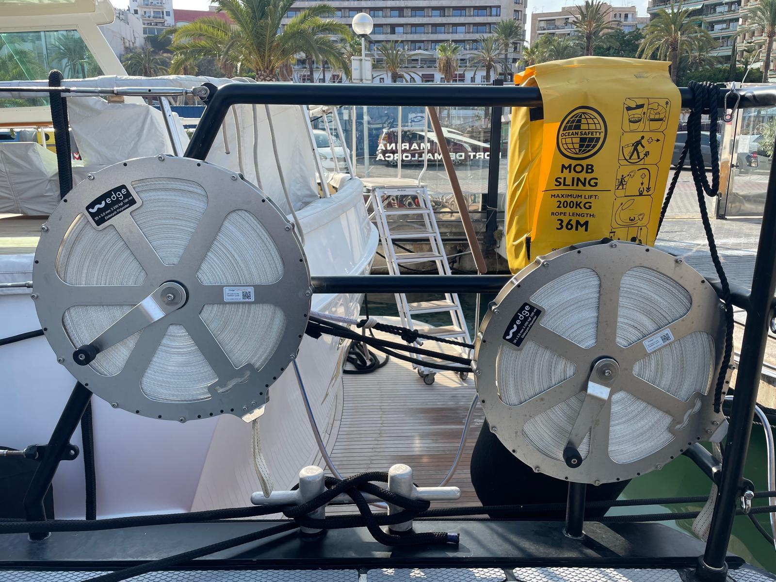
There are also two by 100m Dynema shore reels located on the af deck, Sbd Side. 4000 kg working load. These are provided as Shorefast lines. They should be demounted for use and secured ashore protected from abrasion.
To avoid personal injuries, ensure that limbs, fingers and clothing are kept clear of the anchor rode and windlass during operaMon. Always ensure that there are no swimmers or divers nearby when dropping your anchor.
A separate manual for the anchor windlass is provided with the yacht. Please read this manual carefully.
8.19 MOORING AND TOWING
At several locaMons on deck strong points are fi^ed for anchoring, mooring and towing
Strong poin t
Hull Li.ing cleat
Mooring cleat Fwd
Mooring cleat A.
Sampson post / Sea Anchor point
Descrip-on Size
Strong point through hull loca8on and tow rope anchor
Descrip-on
Fi<ed with bow fairlead for towing/sea anchor
Mooring Lines 6 x 10m x 20mm - Black braided polypropylene -
Storm Lines 6 x 10m x 25mm - Yellow mul>strand
Tow / Kedge
Anchor Line 1 x 30m x 25mm - Orange mul>strand
Main Anchor 110kg - Rocna, galvanised
Kedge Anchor 31kg - Fortress aluminium
Sea Anchor Custom - Retrievable sea anchor for bow or stern deployment. Needs Dynema retrieval line.
Shorefast 100m - Dynema flat ribbon
Mooring cleats are provided on VANGUARD forward, amidships and af. Always use the mooring lines provided on board and double up all lines when leaving VANGUARD moored and un-a^ended. Always check regularly for wear of the mooring lines at the fairleads and mooring ports. Do not use worn, frayed or dirty mooring lines.
VANGUARD can be towed by securing a towline to the Sampson Post sited on the foredeck centerline Fwd of the capstan and/or via a bridle to the two lifing Cleats on the Fwd Quarters When securing to a swinging mooring, a bridle set-up like the towing method allows the anchor to remain in the bow roller.
Warning:
• The owner is responsible for using adequate mooring lines, towing lines and anchor chain and lines.
• The breaking strength of the lines used shall not be more than 80% of the breaking strength of the associated strong point.
• The crew needs to familiarize themselves with a^aching the towing line
• Towing and being towed is done at low speeds e.g. 5 knots.When a^aching the towline prevent using knots that can’t be undone under load.
www.Exploreryacht.com for the journey. Page 56 of 102
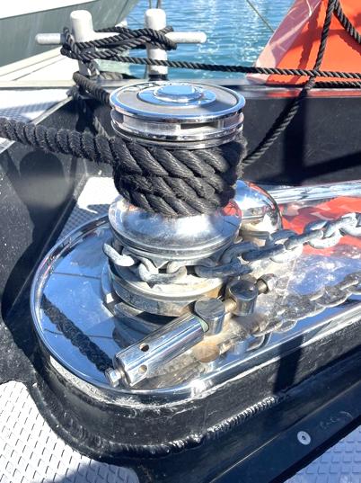
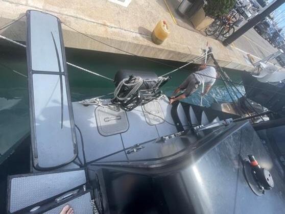
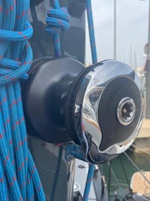
8.20 WINDLASS AND WINCHES
Kedging winches
VANGUARD is fi^ed with two large Maxwell kedging winches on the af deck. These are used for stern anchoring and mooring, especially in the Mediterranean.
• Breakers for two MAXWELL docking winches are in the engine room, above the workshop bench. They should be engaged before docking.
• OperaMon of each winch is via the small deck bu^on adjacent to the winch. It provides for <CLOCKWISE ROTATION> only.
• Winches are torque limited and will only turn clockwise.
• Use 4 or more turns of the dock line for opMmum grip.
Windlass
• Breaker for the MAXWELL windlass and capstan are in the forepeak. This should be engaged before anchoring or docking.
• The windlass should not be used to break out a stuck anchor. Instead, bring the chain verMcal by moving slow ahead and use the momentum of the boat for that purpose.
• Muddy chain should be washed as it comes on board.
• The windlass is fi^ed with a manual ring break that should be engaged at sea and released for operaMon.
• Windlass can be controlled locally using the <HAND/AUTO> switch on the breaker box. Then control with the <UP/DOWN> switch.
• Windlass in <AUTO> can be controlled externally with the <HAND CONTROL>, and extension cable kept in the forepeak
• Windlass in <AUTO> can be controlled from Main Helm staMon (NOT Flybridge) using the UP/DOWN controls
Capstan (Warping Drum)
• The capstan is on top of the windlass.
• First, engage the anchor chain <PAWL> and <BAND BREAK> to secure the anchor chain.
• Disengage the <CLUTCH> using the release bar stored in the forepeak.
• Capstan will operate independently of the Windlass using the same controls.
CauVon
• Windlass, Winches and Capstan are powerful devices. Keep fingers and toes well out of the way and use good seamanship pracMces at all Mmes.
• Do not let children near to these devices if powered up.
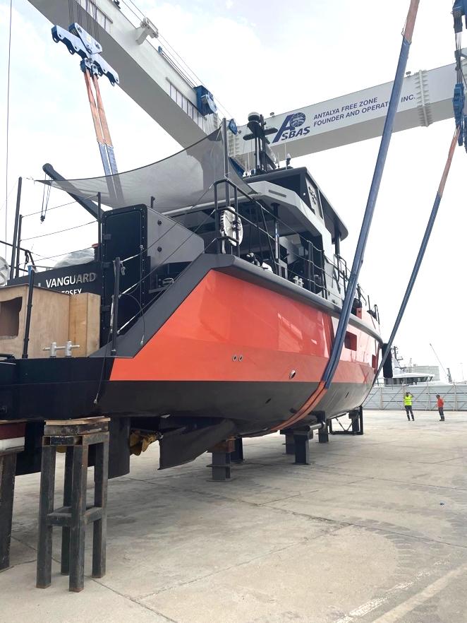
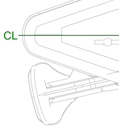
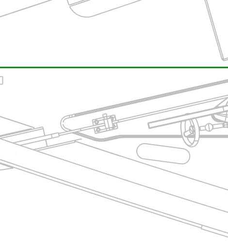
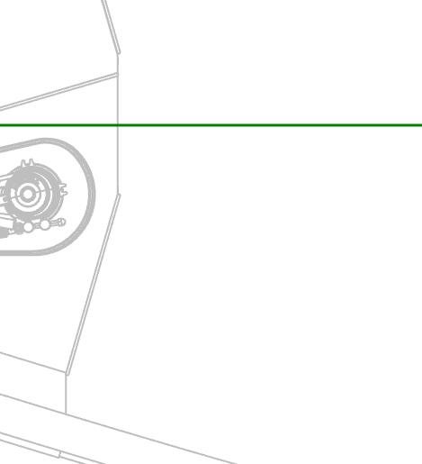
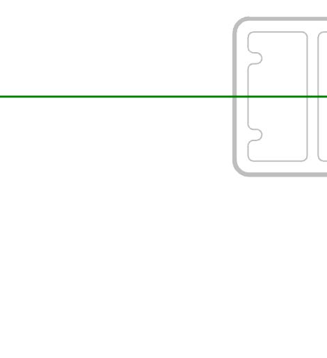
8.21 DRYING OUT AND TRAVEL LIFT
VANGUARD has a long flat and substanMal keel assisted by two equally robust skegs forward of the propellers. The rudders terminate above the lower edge of the skegs. She is designed to take the ground either to careen alongside a quay wall or pile or in emergency situaMons. The normal precauMons must be observed when grounding:
1. The quay or piles are strong enough to take the weight.
2. The ground under the keel is firm.
3. SubstanMal fendering placed against the wall or piles.
4. Only take the ground in calm condiMons.
VANGUARD can also be lifed by a Travel lif (at least 65-ton capacity) sling type arrangement or by crane and slings.
The flat keel on VANGUARD extends from the Forepeak af bulkhead to the forward saf end of the propeller skegs. The longitudinal center of gravity is approximately midships.

9 SAFETY, COMMS AND NAVIGATION
9.1 FIREFIGHTING SYSTEM
9.1.1 PORTABLE FIRE EXTINGUISHERS AND EQUIPEMENT
The portable fire exMnguishers and addiMonal fire fighMng equipment is fi^ed in accordance with the requirements of UK MGN 280. AddiMonally, all internal sof furnishings are treated with EMAFLON Fire retardant in accordance with MGN 580(M), Yachts <50m.


For using the portable fire exMnguisher, remember The "PASS"-word: Keep your back to an unobstructed exit and stand about 2 metres away from the fire. Follow the four-step PASS procedure:
Pull the pin: This unlocks the operaMng lever and allows you to discharge the exMnguisher. Some exMnguishers may have other level-release mechanisms.
Aim low: Point the exMnguisher nozzle (or hose) at the base of the fire.
Squeese the lever about the handle: This discharges the exMnguishing agent. Releasing the lever will stop the discharge. (Some exMnguishers have a bu^on instead of a lever.
Sweep from side to side: Moving carefully toward the fire, keep the exMnguisher aimed at the base of the fire and sweep back and forth unMl the flames appear to be out. Watch the fire area. If the fire reignites, repeat the process.
You should also know that portable fire exMnguishers are valuable for immediate use on small fires. They contain a limited amount of exMnguishing material and need to be used properly so that this material is not wasted.
9.1.2 FIRE DETECTION, ALARM EQUIPMENT AND SMOKE ALARMS
The addressable Praxis Mega-Guard Fire Alarm System (AFAS) monitors 2 different loops on VANGUARD in compliance with EN54-2. The fire detecMon sensors of each loop are connected in a loop and the wiring is connected to the Mega-Guard Fire Alarm System at the Main Helm staMon
The Fire Alarm System is equipped with a 5.7” Touchscreen Operator Panel at the Main Helm StaMon to display detailed fire alarm messages.
• Smoke detectors are fi^ed to: Forepeak, Fwd Cabin, Main Cabin, Af Cabin, Saloon.
• IR detectors are fi^ed in the Engine Room

• AddiMonally, a manual fire alarm call point is also fi^ed in the engine room, forward bulkhead.
The Mega-Guard FAS is connected to the main supply and to the back-up supply for automaMc change over in case of failure of supply voltage. The Mega-Guard FAS is built-up from 5.7” Touchscreen AFAS Operator Panel
9.1.3 Fire & Smoke Alarm Test
• Remove roof-mounted fire detector in Saloon (af by VHF Radio)
• Alarm will sound and then repeaters.
• Replace detector into its holder
• Cancel fire alarm at Fire System Panel Helm. (This may take a few a^empts)
Fire detecMon and smoke alarms
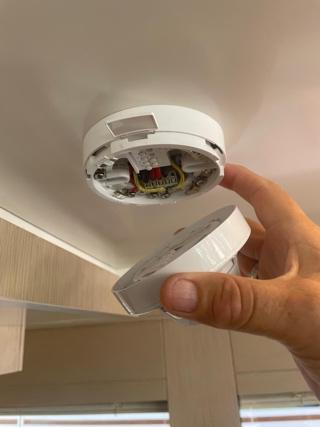
• Fire detecMon and alarm equipment shall be maintained in accordance with the manufacturer’s instrucMons or as indicated on the equipment.
• Smoke alarms shall be tested as part of the boarding rouMne and weekly if aboard for an extended eriod. In the event tesMng a smoke alarm indicates the alarm is faulty, replace the smoke alarm with one of an equivalent type.
www.Exploreryacht.com for the journey. Page 60 of 102
9.1.4 SAFETY WARNINGS
Servicing of fire-fighVng equipment
• Have fire-figh+ng equipment checked at the intervals indicated on the equipment,
• replace portable fire ex+nguishers, if expired or discharged, by devices of iden+cal firefigh+ng capacity,
• have fixed systems refilled or replaced when expired or discharged, have a maintenance schedule available for fixed systems (if fi@ed).
Responsibility of boat owners/operators when the craa is occupied
• Ensure that fire-fighMng equipment is in serviceable condiMon and readily accessible;
• unlock any deck hatches, or any other locked escape openings;
• unlock any locked storage containing any folding or deployable device used to aid escape through a fire exit;
• inform craf occupants about:
1) the locaMon and operaMon of fire-fighMng equipment,
2) the locaMon of any fire port discharge openings into the engine compartment, 3) the locaMon of escape routes and fire exits and to plan acMon in the event of fire.
CauVonary noVces to the craa operator
• Keep the bilges clean and check for fuel and gas vapours or fuel leaks at regular intervals and before starMng the engine.
• When replacing parts of the fire-fighMng installaMon only matching components shall be used, bearing the same designaMon or being equivalent in their technical and fire resistant capabiliMes.
• Do not install free hanging curtains or other fabrics in the vicinity of or above open flame appliances,radiant heat devices or electrical heaMng and cooking elements.
• Do not stow combusMble material in the engine compartment. If non-combusMble materials are stowed in the engine compartment they shall be secured against falling into machinery and shall cause no obstrucMon to access in or from the space.
CauVonary noVces to the craa operator - Specific warnings , NEVER:
• obstruct passageways to fire exits and hatches;
• obstruct access to safety controls, e.g. fuel shut-off valves, gas shut-off valves, isolaMon switches of the electrical system or fire ports;
• deliberately or inadvertently block venMlaMon for compartments or spaces, parMcularly those containing fixed petrol engines, fixed petrol tanks and ba^eries;
• obstruct access to portable fire exMnguishers or fire ports;
• leave the craf una^ended when cooking and/or heaMng appliances are in use unless the appliance is designed to operate una^ended;
• modify any of the craf’s systems unless competent to do so;
• smoke while handling fuel or gas;
• store petrol containers or equipment containing petrol in any area not designated for the specific storage of petrol.
9.1.5 MEANS OF FIRE ESCAPE
The following hatches, doors and other openings are intended to be a means of escape from the interior in case of a fire:


Level
Engine room A^
Fwd
Mid
AF Cabin Cabin
Main Cabin Cabin
Fwd Cabin Cabin
Saloon Main Deck
Main Deck

A^ access to swim plagorm
Fwd access from a^ Cabin
Hatch on Stbd deckhead
Hatch to deck
Hatch to saloon
Hatch for fore deck
Rear access
Pantograph door, Port side
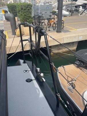
9.2 MAN OVERBOARD PREVENTION & MEANS OF REBOARDING
VANGUARD is equipped for Jackstays that run the length of the hull from Fwd Sampson Post to Af Cleats P&S and from Saloon entrance to Af Tender Cradle, centerline of the af deck. These are Dynema with a 4T breaking strain. When not deployed they are kept in upper Port Af locker.
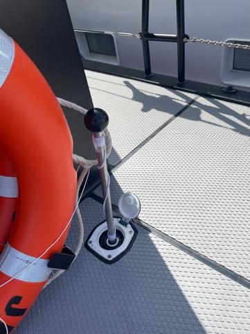
In the event of MOB incident, the following equipment is available to make an effecMve water recovery of concious or unconcious persons:
• MOB Sling on af rail, Stbd side and Life Rings behind the Muster StaMon.
• Swim ladder on swim plaÅorm
• Derrick (1500kg) on Af Deck, Port Side
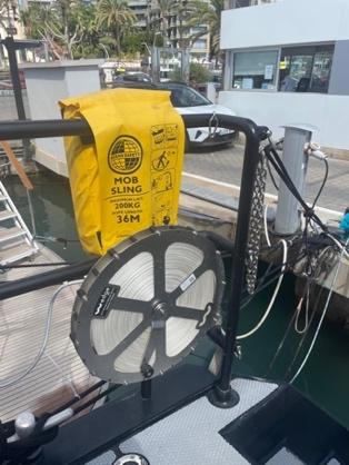

MOB can reboard by using the fold down swim ladder fitted at the Swim Platform.
Warning: Stop the engine during use of the swimming ladder. The propeller can cause injury to nearby swimmers.
Loca-on
Descrip-on
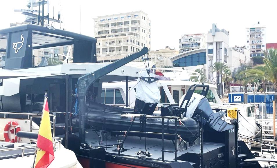
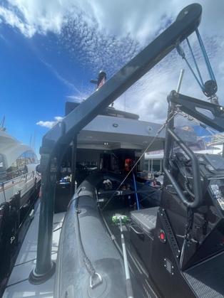
9.3 TENDER - LAUNCH AND RETRIEVAL
VANGUARD is equipped with a 5.0m Highfield RIB itself fi^ed with a 100hp Yamaha outboard motor. The tender is stowed on the af deck. It is launched and retrieved using a 1500 SWL derrick from FEM equipped with a two way Harken winch. The winch can be operated electrically or manually.
Launching the tender is a 2-crew operaMon. One crew working the winch and the other the securing lines allowing the tender to be swung outboard and back inboard to the deck chocks.
Launching the tender
• Stop VANGUARD in calm weather and allow her to come to rest.
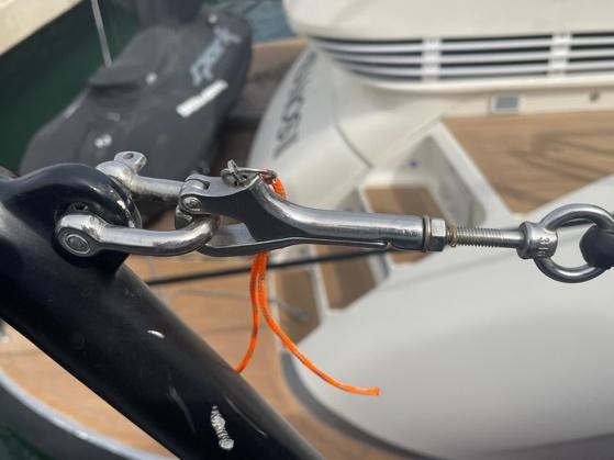
• Remove the Port af railing bar clipping the lines Fwd and Af using the a^ached pelican clips. Remove the af deck Port rail and stow on deck.
• Release the derrick line and flake for use.
• Ensure the spreader bar is properly a^ached to four lifing lugs and at the derrick
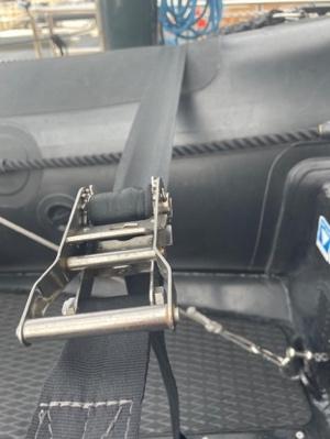
• Release the four retaining cargo straps that hold the tender to the chocks.
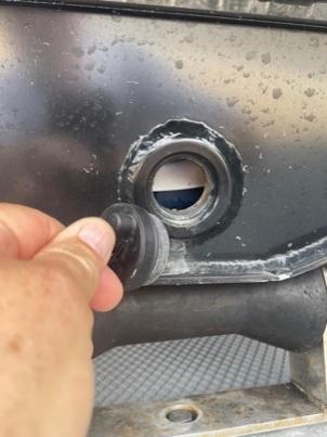
• Install the transom drain plug.
The tender is now ready to lif.
• Move all addiMonal personal to the Stbd side of VANGUARD and forewarn them there will be an approximately 5-degree Port list unMl the tender is in the water.
• Raise the tender to the maximum lif. Swing the stern out and over the side allowing the bow to rotate af facing the opposite way to the hull of VANGUARD.
• Using line fricMon, release the tender line unMl she is floaMng under her own buoyancy. Vanguard will return to a level trim
• A^ach tender bow and stern lines to VANGUARD.
• One crew member (with Life Jacket) can drop down in to the tender, turn on ba^ery, a^ach kill cord, lower and start engine, turn on VHF and MFD Nav system.
• Afer the engine is running, release the spreader retaining cleats.
The tender is now ready for use.
• Replace Port af railing and re-a^ach lines.
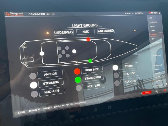
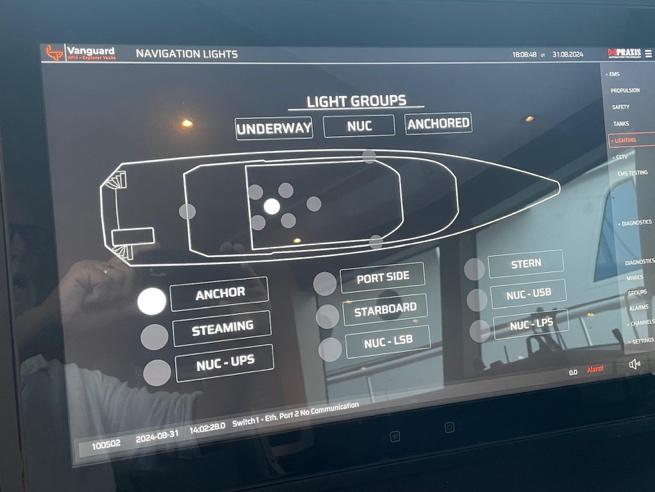
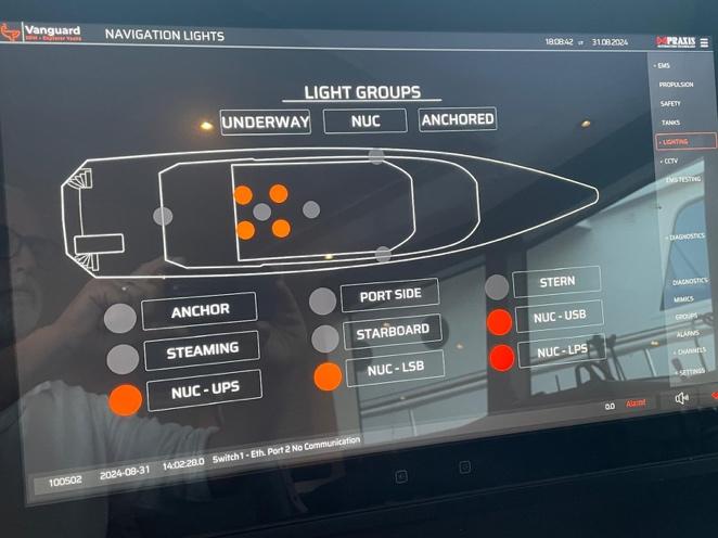
9.4 NAVIGATION AND WORK LIGHTS
All work and NavigaMon lights are single bulb LED units with MTBF of > 50,000 hours. For this reason, lights are not duplicated.
You can switch the navigaMon lights ON/OFF at MIMIC displays on each Helm StaMon. AddiMonally, the lights can be switched manually using small contacts on the Praxis Nav Light PLC, Stbd Helm staMon cabinet.
The following lighMng groups can be switched automaMcally:
• UNDERWAY / STEAMING


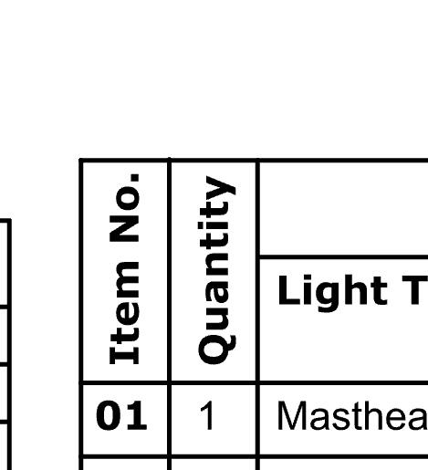


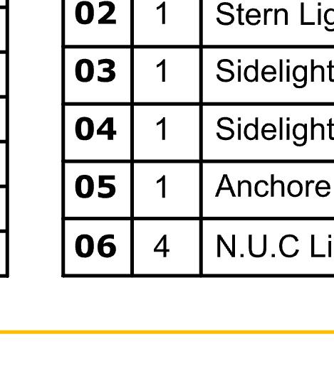
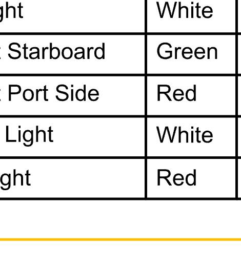


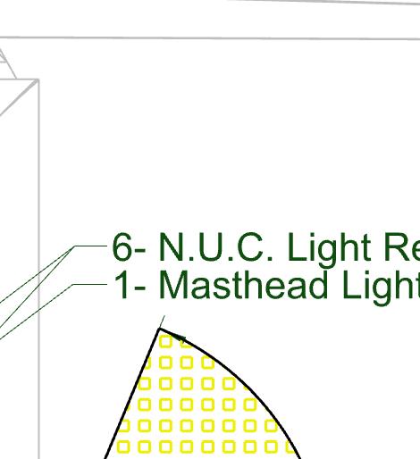


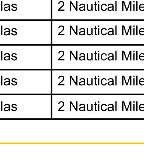


• ANCHOR (in conjuncMon with NUC can signal AGROUND under Rule 30)
• NUC (NOT UNDER CONTROL)
• AddiMonally, night lights (RED) and Cabin air supply are controlled on the MIMIC. RED lights are for use at night when navigaMng. They are at the HELM, GALLEY and AFT CABIN HEAD.
• DECK or working lights are controlled individually on the saloon light touch panel.
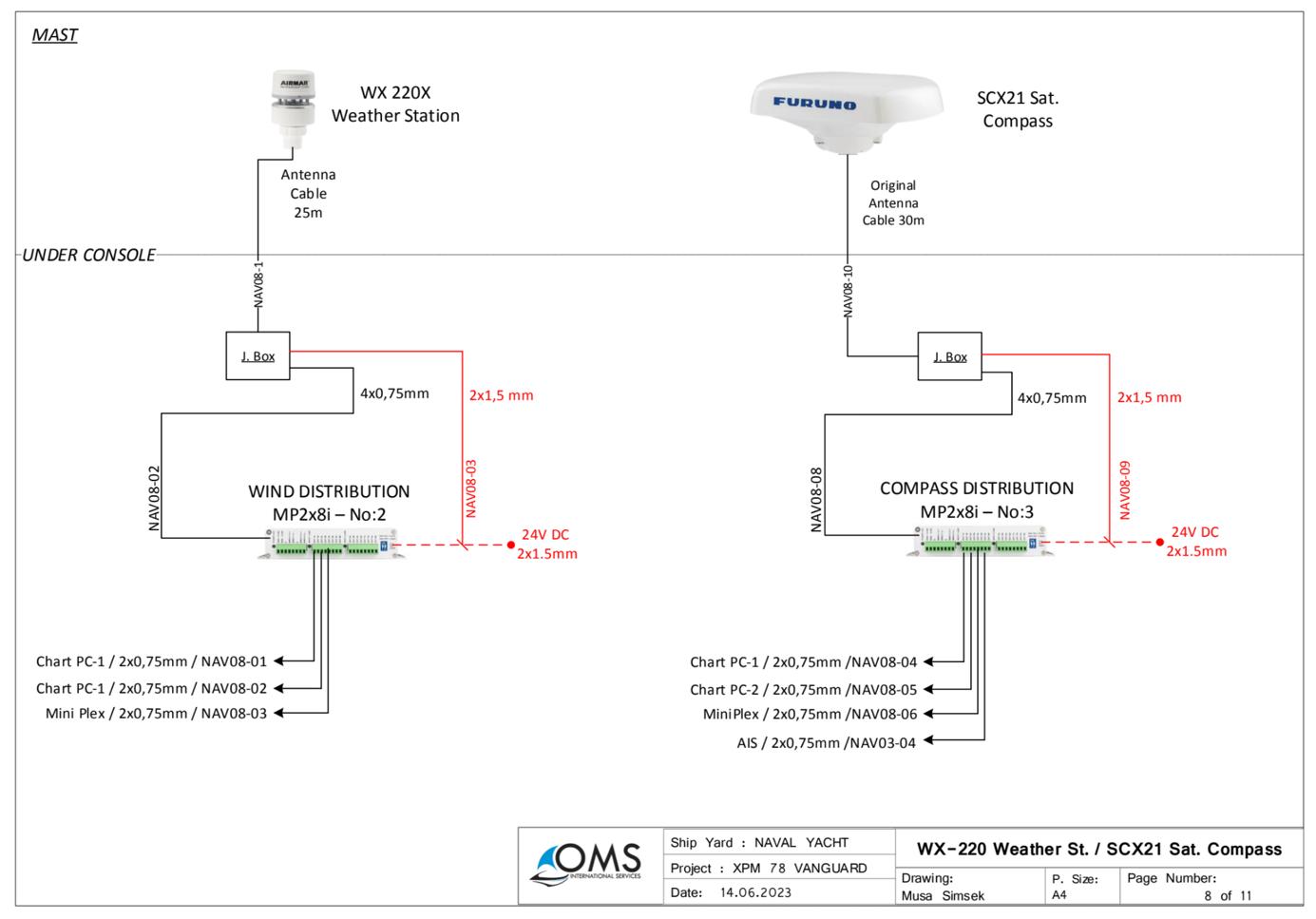
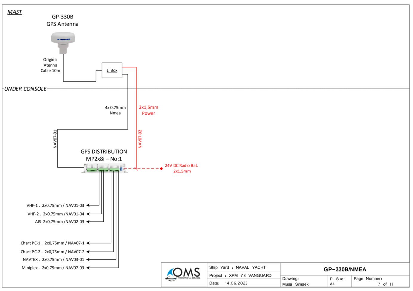
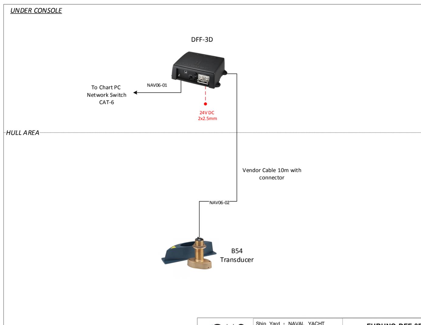
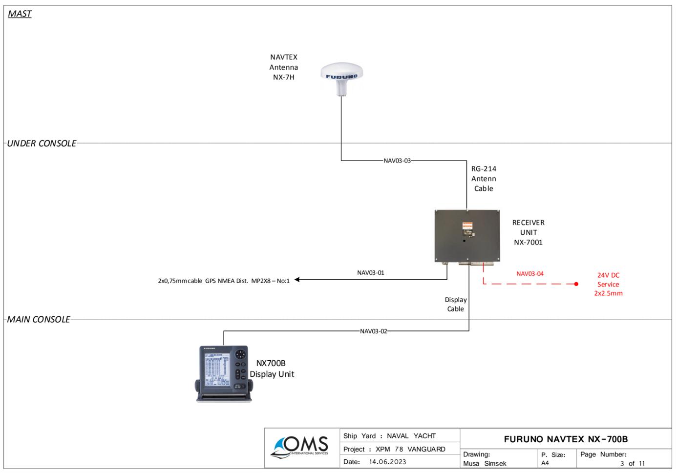
9.5 NAVIGATION, COMMUNICATION & AUDIO VISUAL EQUIPMENT
9.5.1 NAVIGATION EQUIPMENT
NavigaMon equipment is based upon the Furuno range and includes the following:
Equipment
Model No
Descrip4on
AIS (A) FA170 1 Type A commercial
Navtex NX700B 1 NavigaMon updates
Fluxgate Compass PG-700 1 PosiMon GPS
Satellite Compass SCX-21 1 PosiMon GPS, trim, roll, turn
MulFbeam Sonar DFF-3B 1 Benthic topography inc. depth
Depth Transducer B54 1 Depth
Weather StaFon WX-220 1 Temp, humidity, pressure
Airmar DST810 1 Speed, depth, temp
X Band Radar DRS6A 2 Doppler
MFD (Praxis) Praxis 3 Running Time Zero Professional Navpilot 711C 2 Autopilot
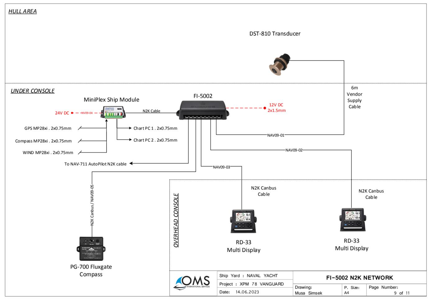
All instruments are networked using NMEA0183 and NMEA2000 CAN. All input can be displayed on MFD and repeater instruments at the main helm and flybridge.
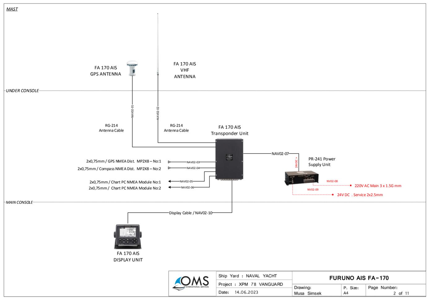
9.5.2 COMMUNICATION EQUIPMET
Equipment
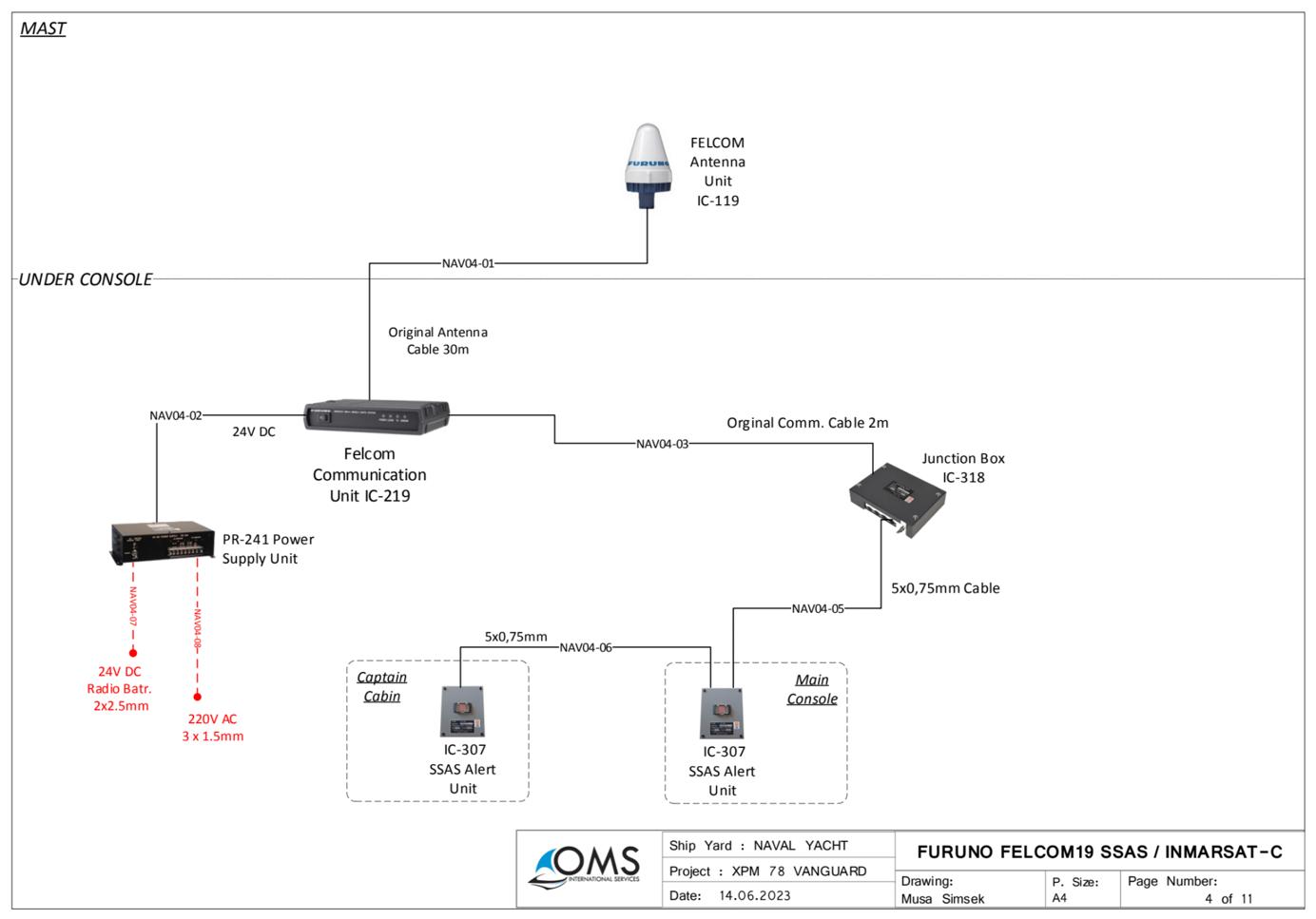
Felcom
Model No Descrip4on
Sat C 1
Emergency transponder (helm & master cabin)
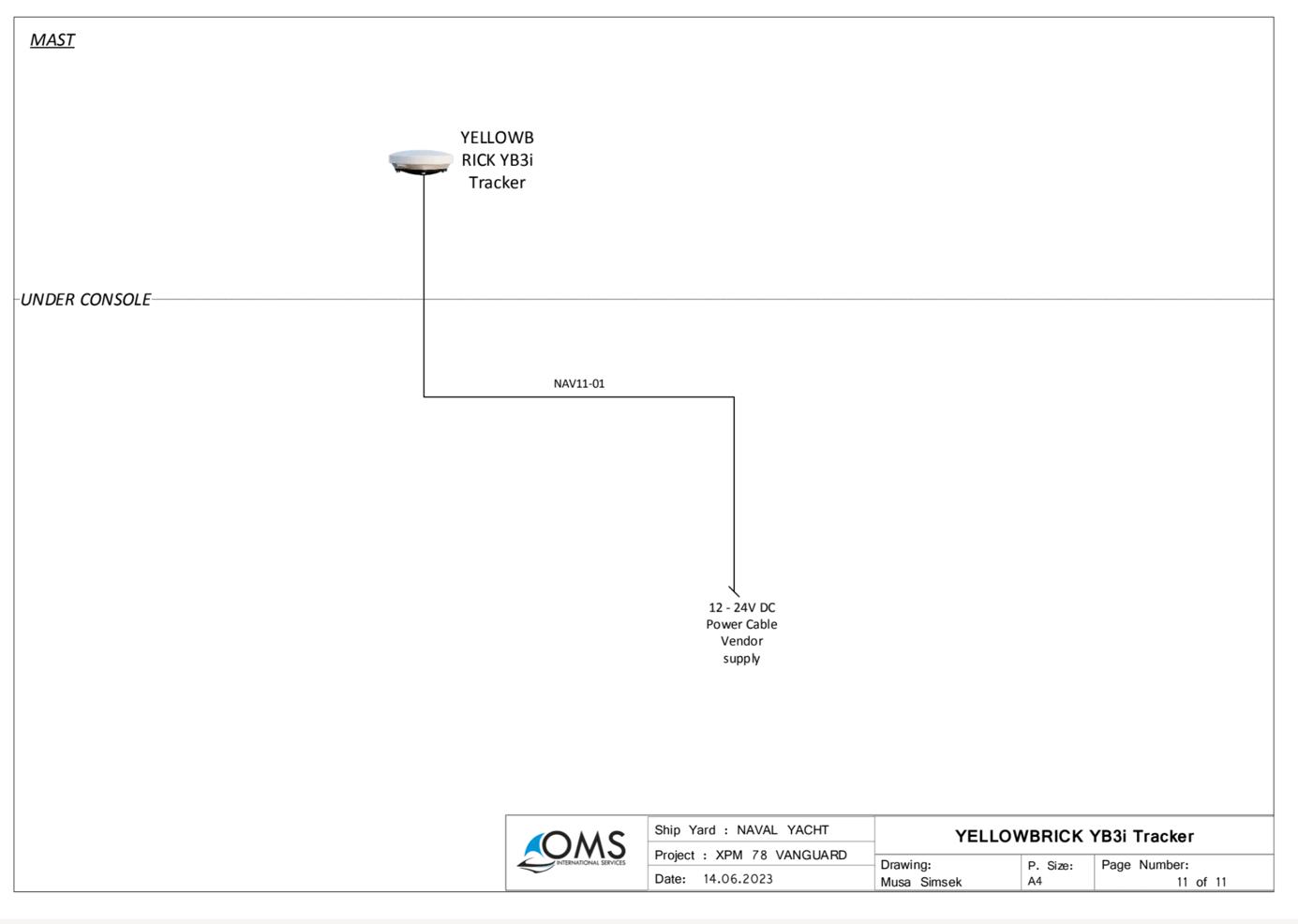
YB3i Tracker 19SASS 1 Emergency tracker
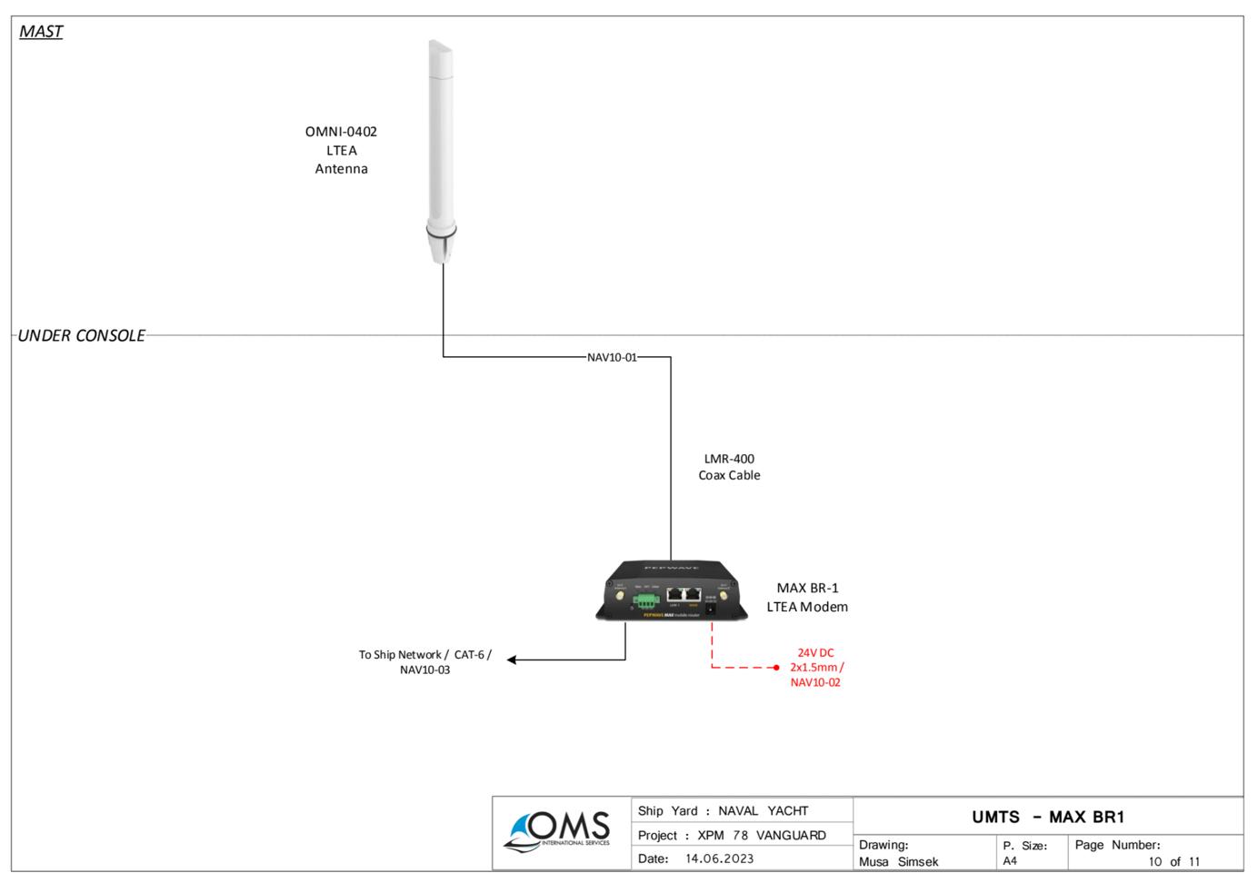
Max BR1 Router 1 WIFI coms, connected to Starlink
Starlink Marine WIFI 1 Sat Coms
Irridium Satcom 1 Sailor 4300 installed but not used in favor of Starlink.
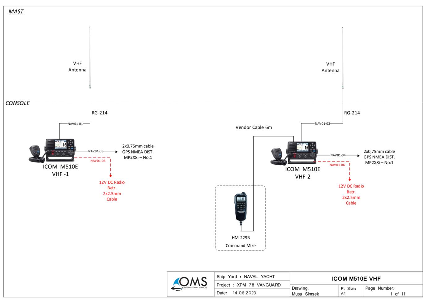
ICom VHF
ICom VHF
ICom VHF
M510E 2+1 Fixed – 2 aerials on Flybridge roof
M94D 2 Handheld
M37 4 Handheld
• CommunicaMons are focused mainly on VHF (both fixed and handheld) and Starlink. Felcom and Yellowbrick remain as emergency response systems.
• Irridium is installed but not presently connected in favor of Starlink.
• Starlink has “Mobile Roaming” access providing Worldwide connecMvity. The Starlink router is linked via WIFI to the main Pepwave Router. The Pepwave signal is boosted by 6 WIFI hotspots sca^ered throughout VANGUARD. Control of priority for Comms is achieved via Peplink sofware. It is possible to connect the WIFI to a SIM card local access via this same system.
• Pepwave Router is also linked by Cat 6 cable (white) to the Praxis System allowing for remote access by Praxis. There is also a local access via another Cat 6 data cable (yellow) used by Praxis when on board. These should not be removed.
www.
9.5.3 AUDIO VISUAL AND YACHT HOTEL AUTOMATION
VANGUARD is equipped with a home automaMon system that controls:
• Internal lighMng in all spaces (excluding red and work lights controlled from Praxis MIMIC)
• Sun/blackout shades in all accommodaMon spaces
• TV actuators in Saloon and Master Cabin
The system is based on Control4 automaMon system and can be operated from a Smartphone. Download the App from the internet to begin using.


addiMonally be
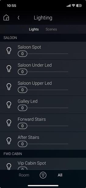

Lights and shades can
controlled from the touch panels in Saloon and each cabin.
9.6 FLIR CAMERA (Daylight & Night Vision)
VANGUARD is equipped with a Military Grade daylight and night vision camera. The camera is located forward of the flybridge on the main helm roof and can be operated using the joysMck at the main helm.
It has an approximately 140-degree field of view looking forward. The image is magnified opMcally and electronically providing for detecMon of human sized objects up to 1500kM forward of the hull. Typically, it will facilitate idenMficaMon of a human face at >400m. The image is gyro stabilized and uses a laser range finder for focus adjustments. It may be viewed either at the operaMng staMon (main helm) or remotely on a laptop by using the IP Address.
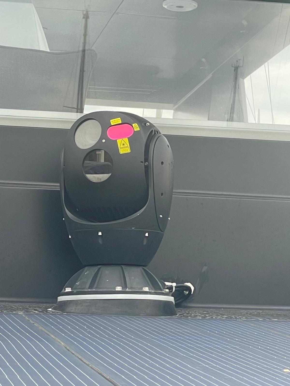
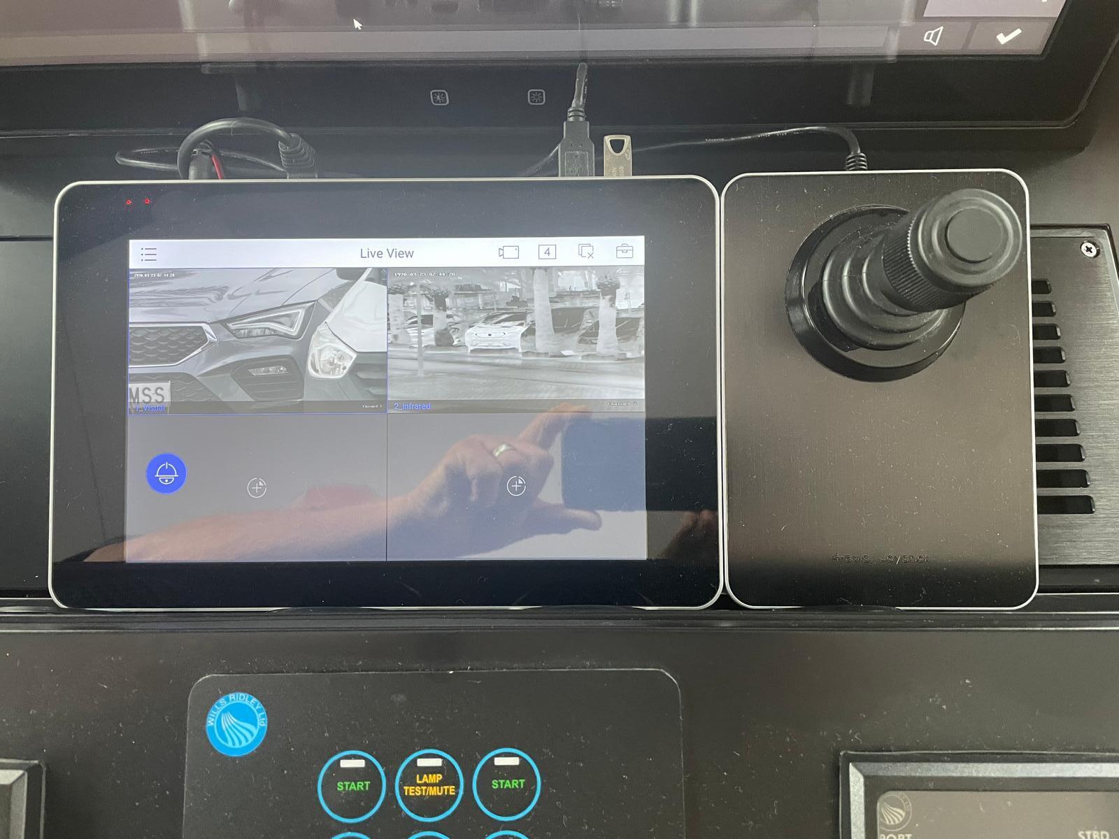
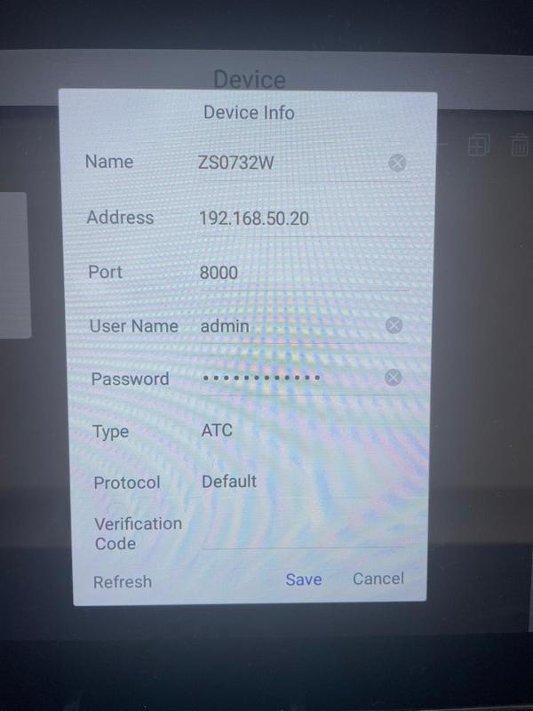
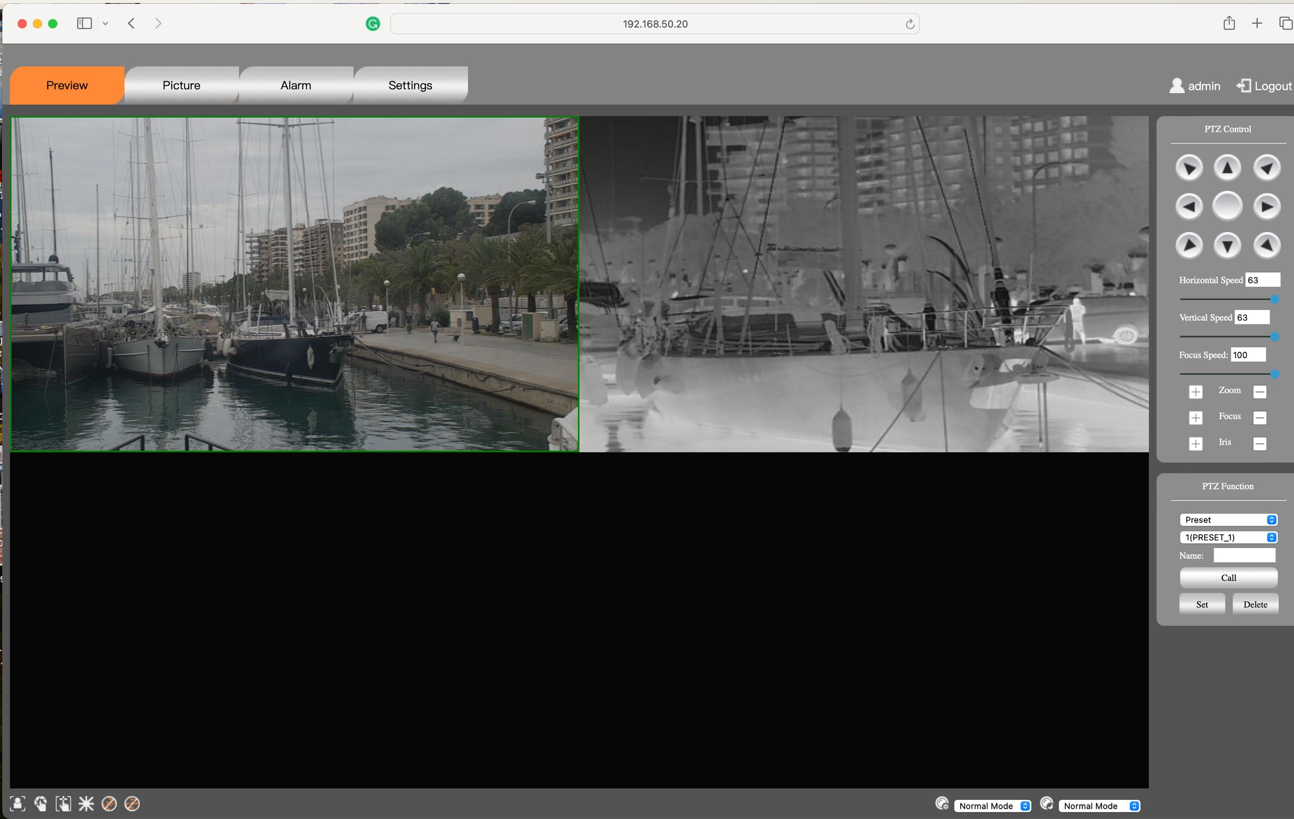
Warning – do not direct the FLIR at military objects as the rangefinder may be a cause of concern!
The FLIR camera viewed via remote access using the WIFI and showing split screen view with both daylight and thermal camera operaMng. See picture below for login on IP 192.168.50.20.
9.7 LIFERAFT STOWAGE
VANGUARD is equipped with two SOLAS approved liferafs.
They can be accessed from the flybridge and will automaMcally inflate when released. In the event of foundering, they are also fi^ed with an automaMvc hydrostaMc release.
Servicing of life raa:
SOLAS approved life rafs are a survey inspecMon item and are serviced yearly as indicated on the service record label.
9.8 DECK CRANE OPERATIONS
VANGUARD is fi^ed with a custom folding derrick for tender and stores operaMons. (See also 8.3 – Tender Launch and Retrieval)
• The derrick is fi^ed in a PTFE lined socket on the Port /Af deck.
• SWL 1,500 kg, tested to 2,500kg
• Electric 24VDC Harken 2-way winch with manual override and winch line break
• RotaMonal slewing is manual.
• Spreader bar for tender operaMons and hook swivel.
The boom can be folded when not in use by removing the rear S/S pintle and manually lowering. In pracMce it is generally lef a^ached to the tender ready for lifing.
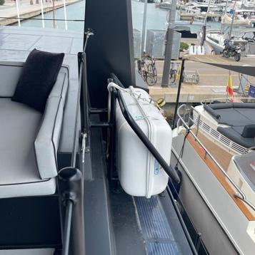
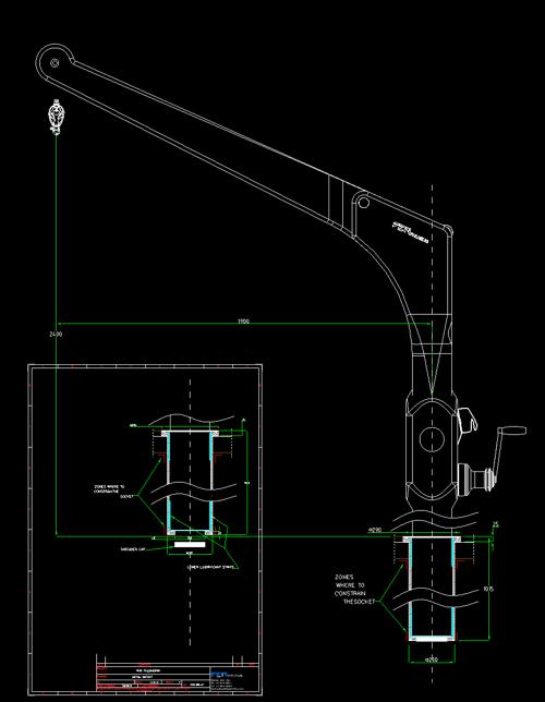
The maximum Safe Working Load (SWL) of the deck crane is 1,500kg. The crane should not loaded with a higher load.
9.9 SECURING OF LOOSE EQUIPMENT
To avoid personal injuries always secure loose equipment safely. Pay parMcular a^enMon prior to departure to equipment and stores in the:
• Deck & flybridge
• Galley
• Engine Room
Make sure that equipment close to machineries shall be secured against falling into machinery. Materials are available in the rigging locker for securing equipment that may move in a seaway. Loose equipment shall cause no obstrucMon to escape exits.
9.10 IN HULL PORTS & HELM WINDOWS
Window openings in the hull below the weather deck are triple laminated toughened glass to ISO11336-1 fi^ed so as not to protrude beyond the hull surface. Windows are symmetrical Port and Stbd and provided with one blank per pair in the event of rupture. Blanks are stored in the cabins; blanking bolts are stored in the muster staMon.
Make sure that the helmsman has all round visibility at all Mmes. The field of vision from the main helm is 180 degrees FWD from Port to Stbd side. Windows in this locaMon are in Area 2 and unMnted triple laminated toughened glass. Window strength is calculated according to ISO11336-1 as >1.5 Mmes the equivalent strength as 5mm 5000 series marine grade alumninium sheet and on that basis no blanks are required in this locaMon for operaMon at sea.
Note: penetraMons below the weatherdeck are provided with window boards in the event of failure. One board is provided for every window pair (P&S). One bolt is fi^ed every two holes. Bolts are located in the muster staMon cabinet. Boards are located in the cabins, under the bunks.
Note: the main helm pantograph door is provided with a wash board for use when open at sea. The. Was board is stored under the adjacent seaMng. Bolts are kept screwed in to their respecMve threads on the door frame.
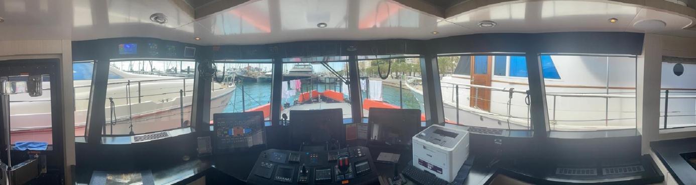
The Operator’s vision from the helm can be obstructed by high trim angles of the yacht and other factors caused by one or more of the following variable condiMons:
• Speed & Sea condiMons.
• Rain and spray – Note: the forward main helm is fi^ed with a wiper operated from the helm.
• Interior lights – Note: all instruments in this locaMon can be dimmed for operaMon at night.
• Persons or movable gear in the operator’s field of vision.
The internaMonal RegulaMons for PrevenMng Collisions at Sea (COLREG) require that a proper lookout be maintained at all Mmes and observance of right of way.
Warning:
• Do not sail at full speed in adverse weather condiMons like; limited visibility, high winds or high waves.
• Make sure to have sufficient distance to other vessels to be able to stop or change course in order to prevent collisions.
• Spray and rainwater limit visibility form the helm posiMon, as can dawn, dusk or mist.
• The internaMonal rules for prevenMon collisions at sea (COLREG) and good seamanship require you to maintain a good lookout in all circumstances. Be sure there are no other vessels in your way before you proceed.
www.
9.11 HULL CONSTRUCTION
The construcMon of VANGUARD consists of a hull of 5000 series marine grade aluminium. She is designed as an explorer yacht to work in remote locaMons. As such both the scantlings and hull thickness are considerably greater than required by Small Yacht Code <24m requirements.
• Hull thickness below the weather deck is 12mm
• Stem, keel and skegs are 25mm, Deck at the weather deck is 8mm, Hull Stringers are 100mm depth.
• The hull is designed to sit upright when dry by means of two substanMal skegs fi^ed at the stern and supporMng the propeller shafs.
• Rudders will remain clear of the floor when in this posiMon.
• Rudders are also provided with a lower 1/3 that can crush and a pintle being 100% increase on Code requirements.
• The lower hull is a double bo^om structure meaning that rupture in this locaMon will result in loss of a tank but will not result in flooding to any compartment. The two excepMons ae the forepeak and engine room outside of the Glycol storage tanks.
• The hull is fi^ed with a crash zone in the forward 1m and 3 further waterMght compartments up to the weather deck
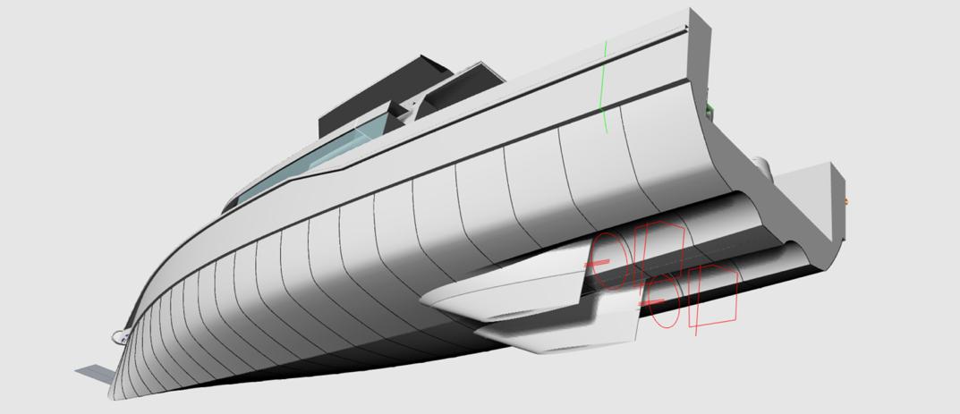
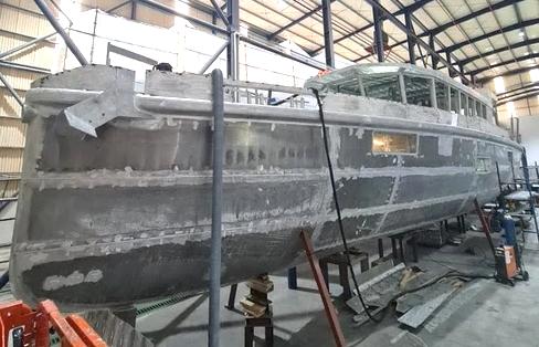
It is the responsibility of the owner for ensuring that the normal mode of operaMon is maintained. This will mean that the speed of the yacht will need to be matched to the prevailing sea state.
10 ENVIRONMENTAL CONSIDERATIONS
Be aware of local environment laws and respect codes of good pracMce.
10.1 FUEL AND OIL SPILLAGE
In all cases avoid spilling fuel and oil in the open water.
When refuelling, watch the level meter, slow down when reaching the end and make sure you have absorbing materials, like cloth, nearby.
When you need to refresh the engine oil, collect it and deliver it to the designated place. In most harbours these places are available.
Oil spilled in the bilge must not be pumped over board. Clean the bilge with cloth and deliver also these to the designated place in the harbour. Finish cleaning the bilge with decomposable soap. In general keep the bilges as clean as possible.
10.2
DISCHARGE AND DISPOSAL OF WASTE
Every substance you waste in the yacht, will be pumped over board by the bilge pumping system. Therefore, turn off the pumps and clean the bilge by yourself and deliver waste to the designated place in the harbour
Be aware of internaMonal regulaMons against marine polluMon (Marpol) and respect it as much as possible.
10.3
EXCESSIVE NOISE AND EXHAUST EMISSIONS
Although the engine is sufficiently isolated and the emission saMsfies the criterions, you must reckon with the possibility you are disturbing others.
Consequently, when you feel you have to slow down, please do so. And beside these facts, just remember to respect the local speed limit.
10.4
WAKE AND WASH
Drive at low speed to reduce the wave heights at places where you can disturb other boats, or even damage the bank.
10.5 PAINT, CLEANING AGENTS AND OTHER SUBSTANCES
It is important to know what substances you are dealing with. A lot of them can do harm to the environment.
Please don’t dispose of paint, dust from sanding and thinner, in the sink or bilges. Collect it and deliver it to the designated place in the harbour.
For cleaning your ship, it is recommended to use decomposable soaps, as these will not affect the environment.
In the case of damage to the fridge, make sure the system is not leaking. If so, immediately consult a professional. Also materials like engine cooling fluid will harm the environment, so they must be treated with care and also delivered to the designated place.
10.6 WASTE MANAGEMENT PLAN
Ocean going vessels of 40 feet or longer with a galley and berth must have a wri^en Waste Management Plan.
All persons boarding this vessel, VANGUARD be aware that under NO circumstances will any garbage, plasMc material, food, aluminum cans, bo^les, sewage and hazardous substances, etc. be thrown overboard. You must also advise the captain in case of any oily discharges or diesel spills that you might observe.
• There is a trash receptacle located: GALLEY.
• Cans and bo^les are recycled and have a special receptacle located: GALLEY.
When a trash receptacle is full, the crewmember appointed by the skipper in charge will bag all material and secure the bag unMl it can be removed from the boat and placed in an appropriate receptacle on shore.
UNDER NO CONDITION WILL ANY TRASH BE THROWN OVERBOARD FROM THIS VESSEL, A simplified overview of the discharge provisions of the revised MARPOL Annex V which will enter into force on 1 January 2013 has been developed by the IMO and is presented here below
QuesMons concerning this policy, please see the captain of this vessel
C Leigh-Jones for and on behalf of Vanguard XPM LLC
Owner/Captain
THIS IS ALSO A ZERO TOLERANCE, DRUG FREE, VESSEL.
Ref for Waste Management Plan, US CG Auxiliary.
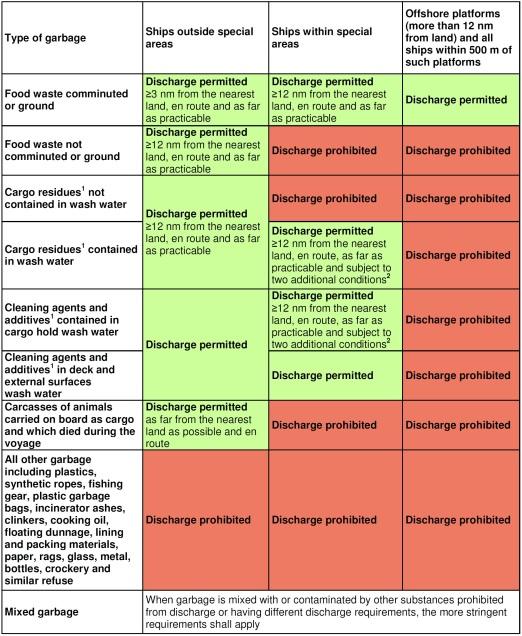
11 MAINTENANCE
11.1 GENERAL CARE
Regularly maintenance keeps your vessel in good condiMon. Maintenance should be performed by qualified personnel.
11.2 CLEANING
Periodic cleaning is the best way to keep your boat looking like new. Regular washing and waxing keep dirt and build-up from deterioraMng the finish. Thoroughly clean the hull, deck and interior of the boat from Mme to Mme.
When washing the boat, be sure to use a mild detergent and warm water soluMon. DO NOT use abrasive cleaners, solvents, ammonia or chlorine, as these will damage the paint coated surface. Under extreme condiMons, special cleaners may be used to remove marine growth from the hull.
Whenever the weather makes it possible, air and venMlate regularly your boat. Make sure that the bilges are clean and dry.
11.3
WINTER STORAGE
The storage or winter lay-up requires special preparaMon to prevent damage to the boat. Since winter storage is an annual event, it presents an excellent opportunity to perform the annual maintenance at this Mme, depending upon the amount of usage.
Without proper preparaMon, storage for long periods of Mme may cause internal parts of the engine and transmission to rust due to lack of lubricaMon. Also, if the boat has been stored in below-freezing temperatures with water inside the bilge, engine cooling system, fresh water system, grey and black water system, this condiMon may result in major damage from freezing.
All the systems containing water should be empMed during storage at freezing temperatures.
Praxis power ba^eries will need an elcrical connecMon to maintain charge if storage is intended in excess of 2 months.
Refer to the engine owner’s manuals regarding oil changes. The boat should have an oil change performed immediately prior to storage to prevent potenMal damage to the engine.
Because of the complexity of preparing a boat for proper winter storage, as well as the possibility of extreme damage to the yacht if a preparaMon error was made during winterizaMon, it is highly recommended to schedule an appointment with an authorized service department to permit a technician to perform all winterizaMon procedures.
www.
11.4 LIFTING OF THE BOAT
See also SecVon 7.0
An overhead hoist with a minimum of 65 ton capacity should be used. The longitudinal center of gravity is approximately 13/14m af from the bow.
Use a wide-enough spreader bar on each sling to prevent damaging side pressure to the deck or gunwale moulding. Lifing slings must never contact shafs, stabilisers, hardware other protruding from the hull as this may result in damages. Lifing slings should be secured with a line to prevent sliding of the slings.
AddiMonally, VANGUARD is equipped with 4 structural lifing cleats as indicated in the diagram below. These extend downwards in to the hull and can be used to lif the vessel in situaMons where a sling is not available. The use of a spreader bar is also recommended for this situaMon.
When the boat is out of the water, it is important to support the hull correctly to avoid any hull damage.
If a storage cradle is used, the hull must be properly supported to prevent load damage. Protect all items extending from the hull (i.e., propeller, etc.) to prevent them from resMng on the cradle or the ground. Do not apply any load stress to the propeller, shaf, water intake grate or other protruding items.
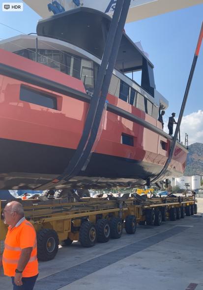
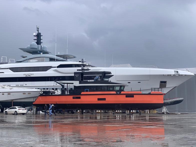
12 SYMBOLS AND SAFETY WARNINGS


General warning sign.
To indicate a risk of personal injury.
Read owner's/operator’s manual.
To direct reference to an owner/operator handbook for addiMonal informaMon.
Danger of fires.
To indicate the risk of fires.


High voltage warning symbol. To indicate the risk of electrical shocks.


Hot surface warning symbol. To indicate a risk of personal injury by hot surfaces.
Escape direcMon / escape way


Muster StaMon

Designated place of the first-aid kit or locker where it is stowed
Designated place of portable fire exMnguisher (Inc Fire Blanket) or locker where it is stowed
ISO Class A: Fires involving solid materials, usually of an organic nature, in which combusMon normally takes place with the formaMon of glowing embers.
ISO Class B: Fire involving liquids or liquefiable solids.
ISO Class C: Fires involving gases.
No naked flames; Fire, open igniMon source and smoking prohibited. To indicate a possible failure or malfuncMon.
A red colour indicator with a basic symbol may be used alternaMvely to indicate a malfuncMon
Fixed fire exMnguisher locaMon.
13 ACCEPTANCE DECLARATION & RECEIPT OF DOCUMENTATION
The builder:
Address: Naval Yat
Ada 43,60/3 Parsel Liman Serbest Bolge Mah, 3Sk
No: 16 KonyaalM Antalya Turkey
• Naval Yat, failed to complete VANGUARD to an adequate standard in that systemes were not commissioned in a Mmely manner and omissions went uncorrected. The owner is a qualified Chartered and Marine Engineer and took over compleMon of the build including commissioning each system on board and ongoing repairs/correcMons to those systems as necessary. This was completed over 6 month period starMng April through September 2024. Work was in many cases subject to oversight by UK MCA through the Category (0) survey process and three surveyor visits during that period.
• OperaMons and Training Manuals were prepared by the Owner using CE and MGN 280 as guidelines.
• Herewith declares to have delivered the VANGUARD, with WIN-code as given on the declaraMon of conformity, and joining owner’s manual and all other documents and manuals belonging to the boat.
The owners:
Name: VANGUARD XPM LLC
Address: C/O Sayer Regan & Thayer LLP
130 Belleveue Avenue Newport RI 02840 USA
Herewith declares for the acceptance of the yacht and the receipt of a complete owner’s manual, all other documents and manuals belonging to the yacht.
On behalf of the producer of the yacht: Owners of the boat:
Name:
Date:
Name:
Date:
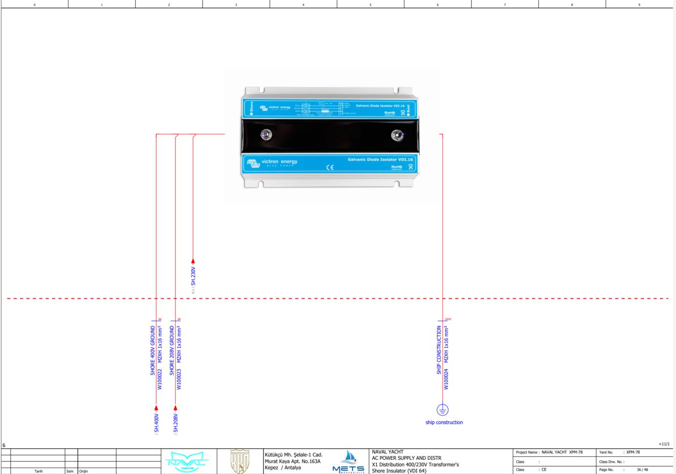
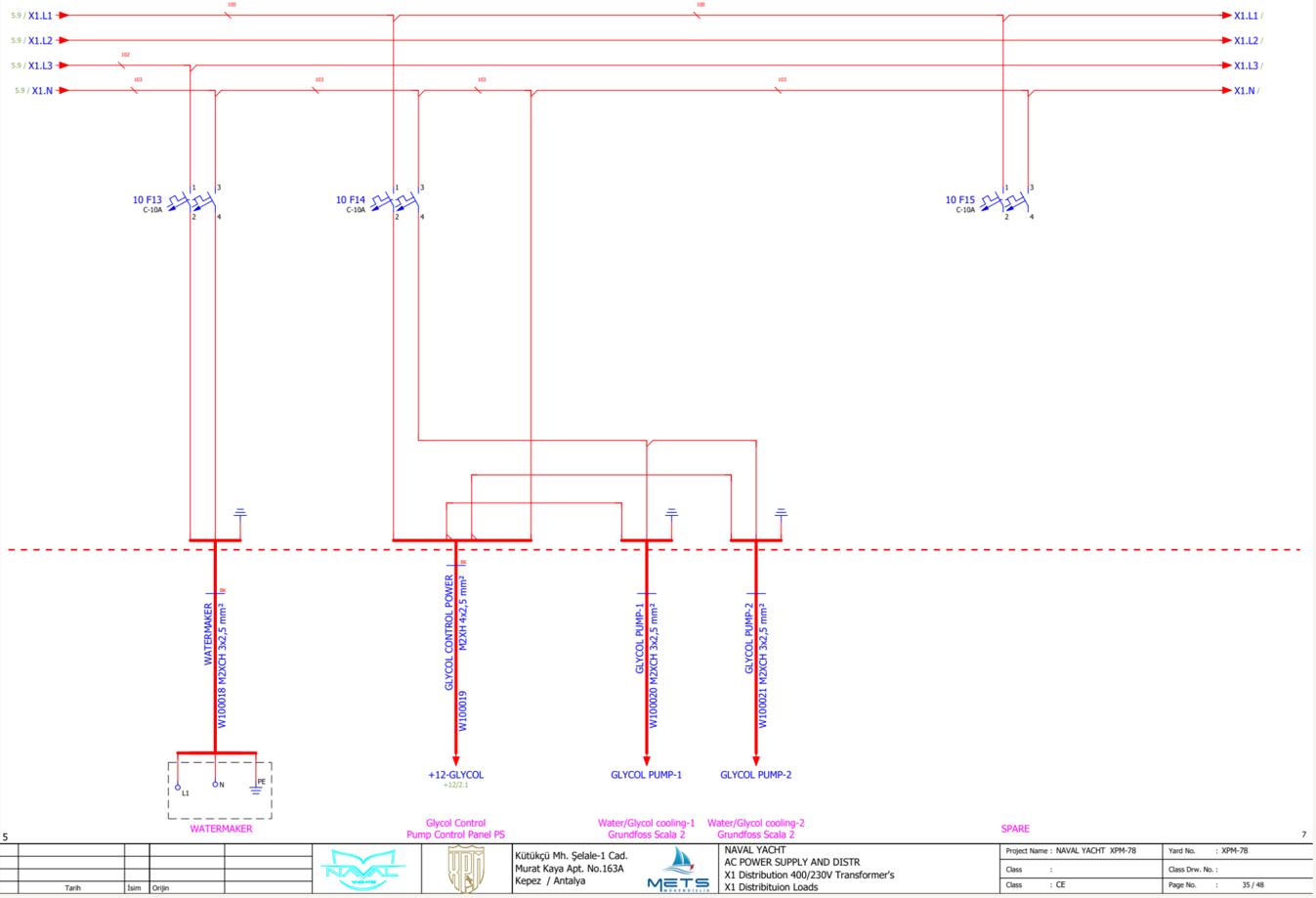
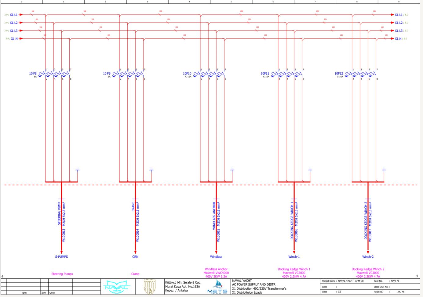
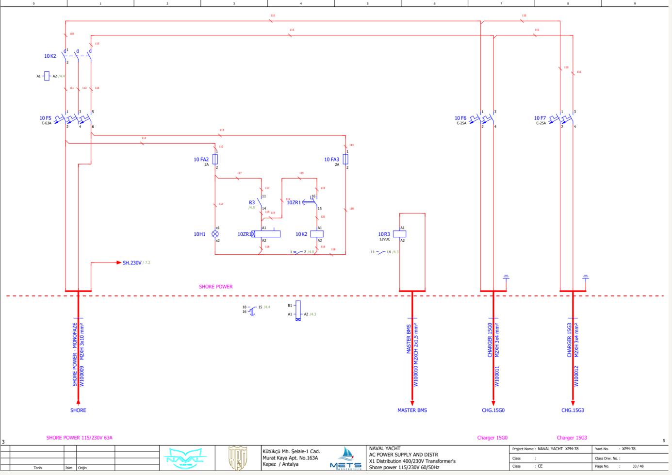
www.Exploreryacht.com for the journey. Page 84 of
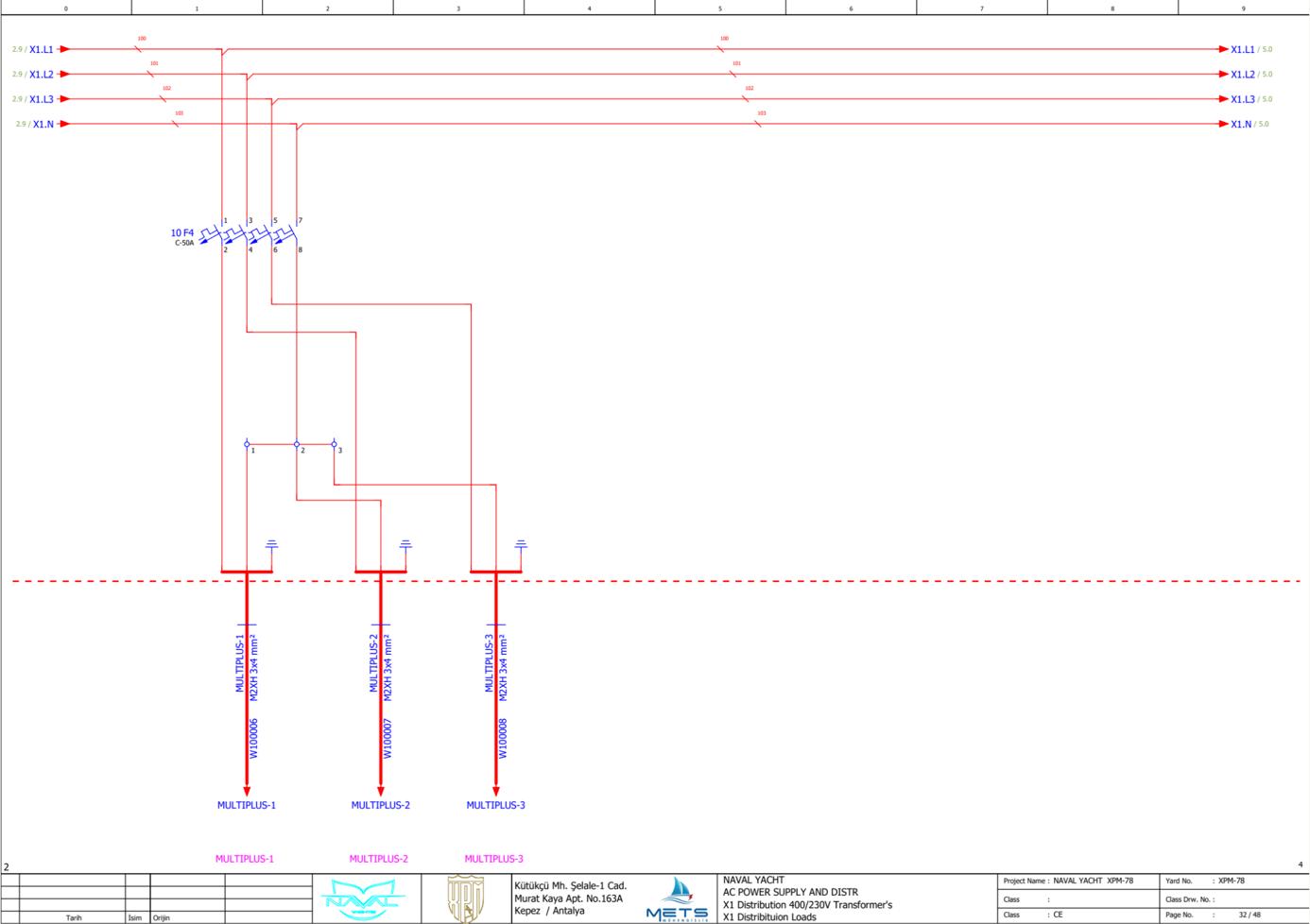
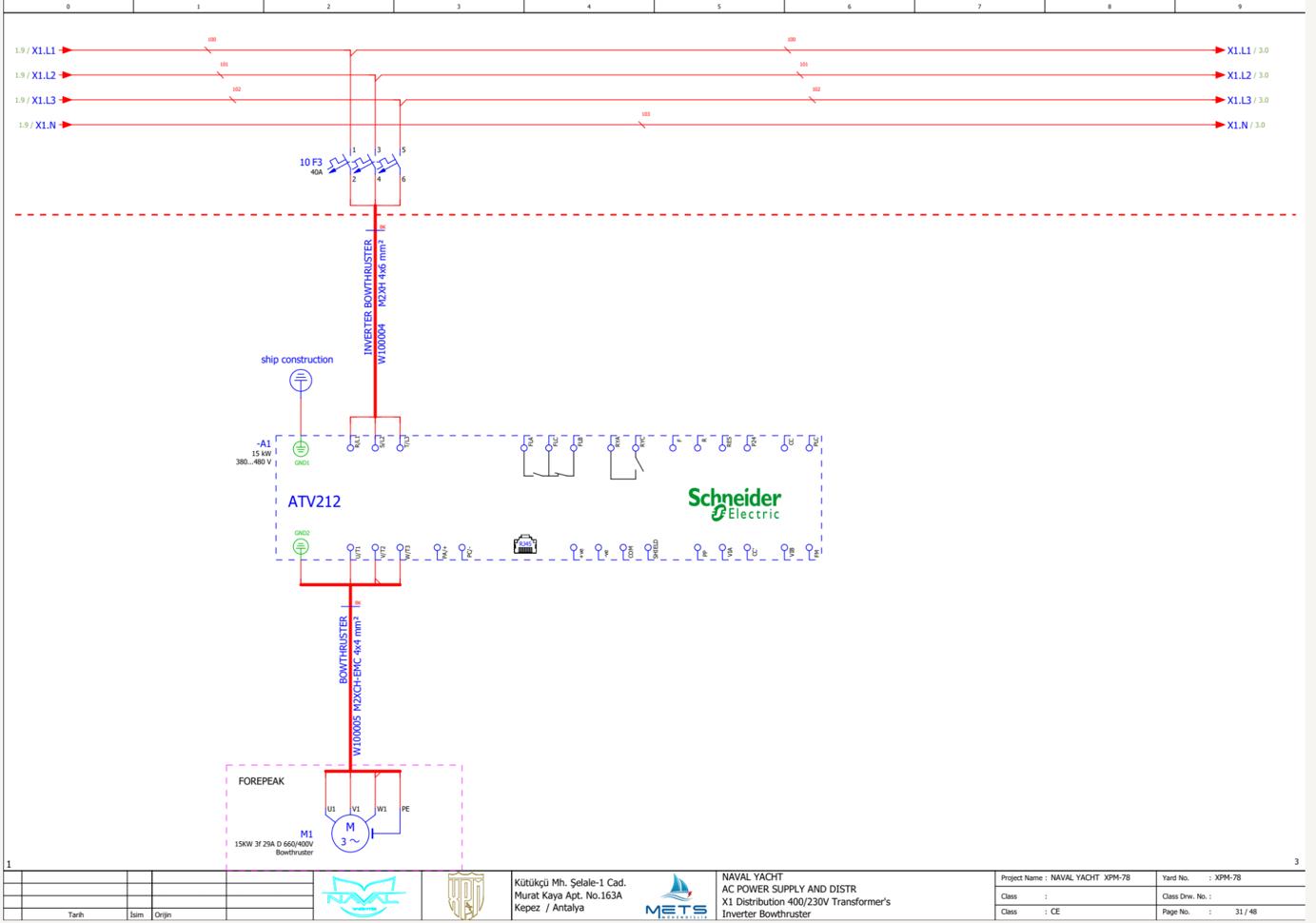
www.Exploreryacht.com for the journey. Page 85 of
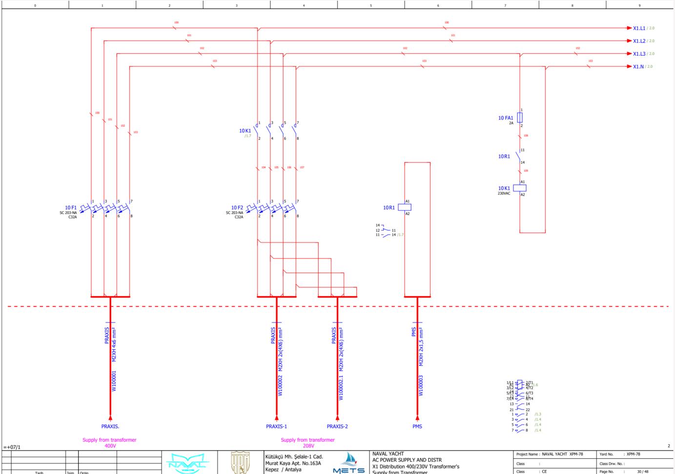
www.Exploreryacht.com for the journey. Page 86 of
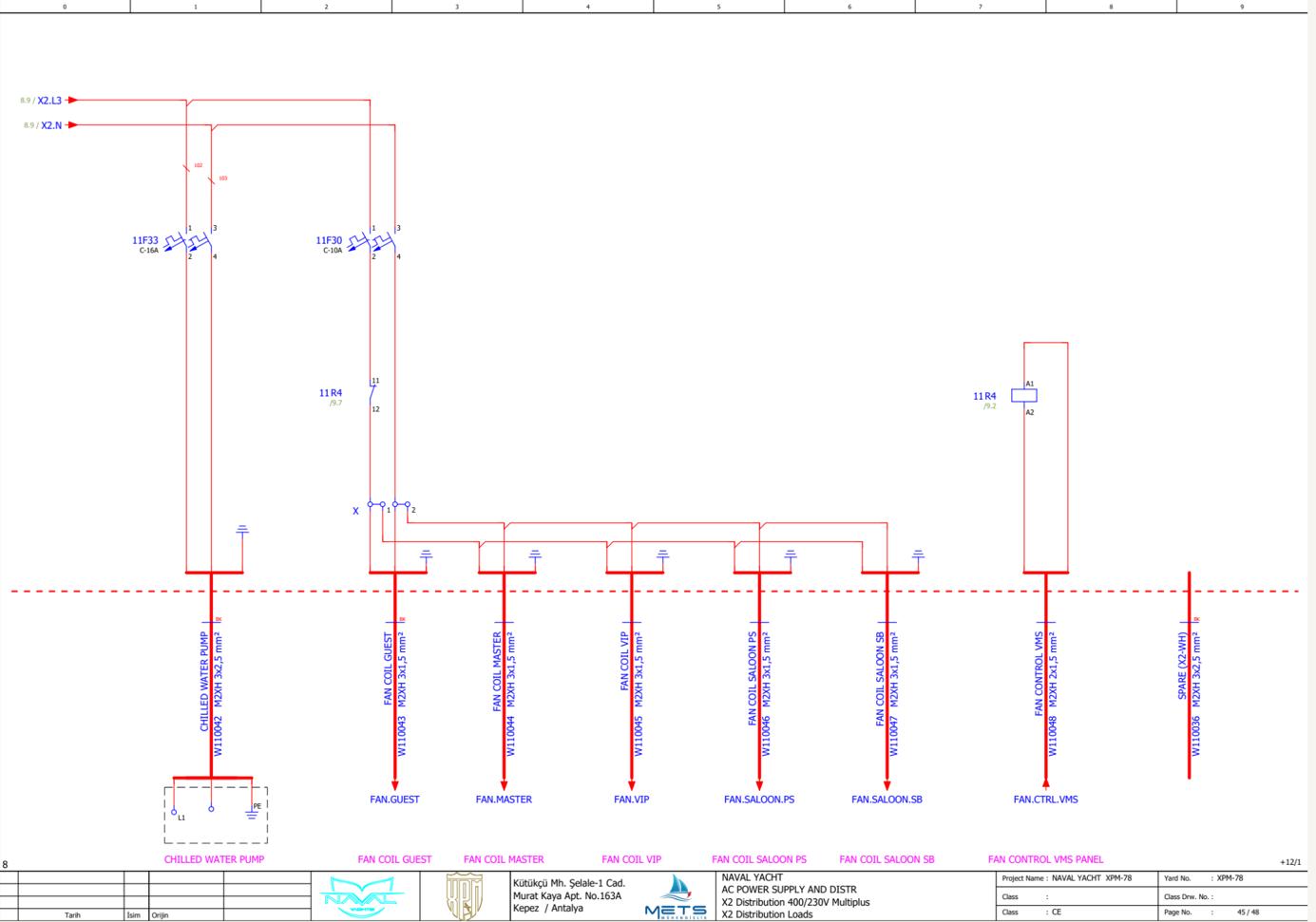
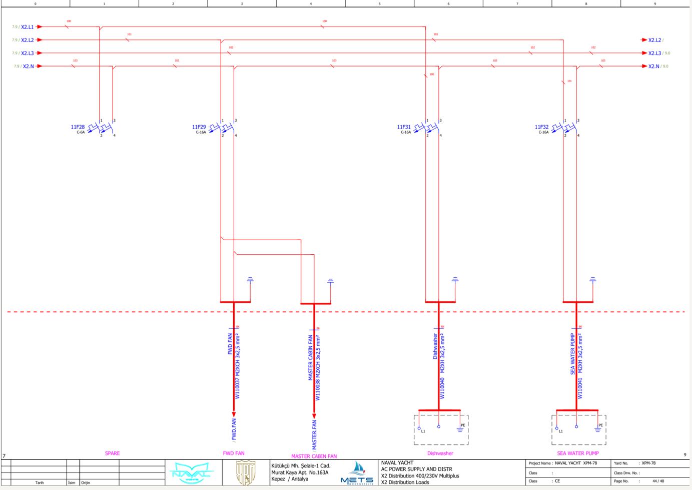
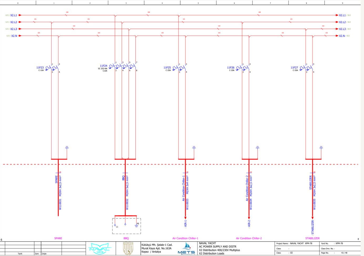
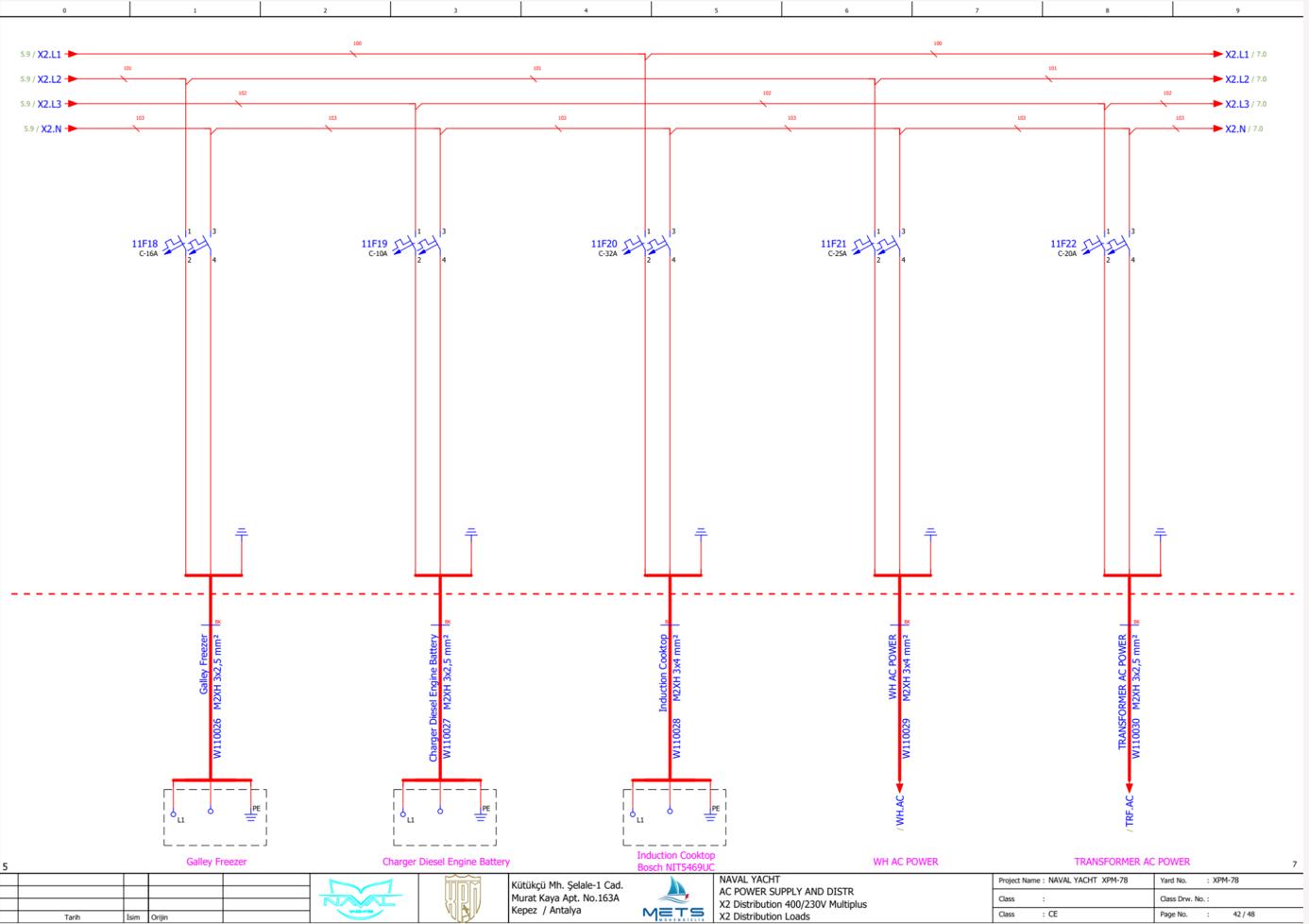
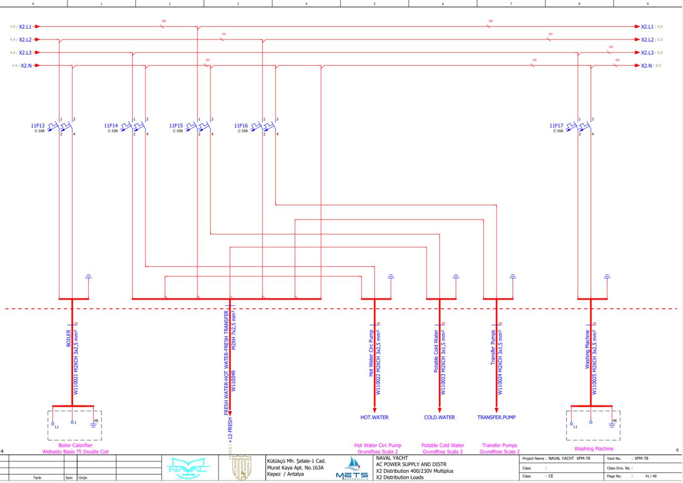
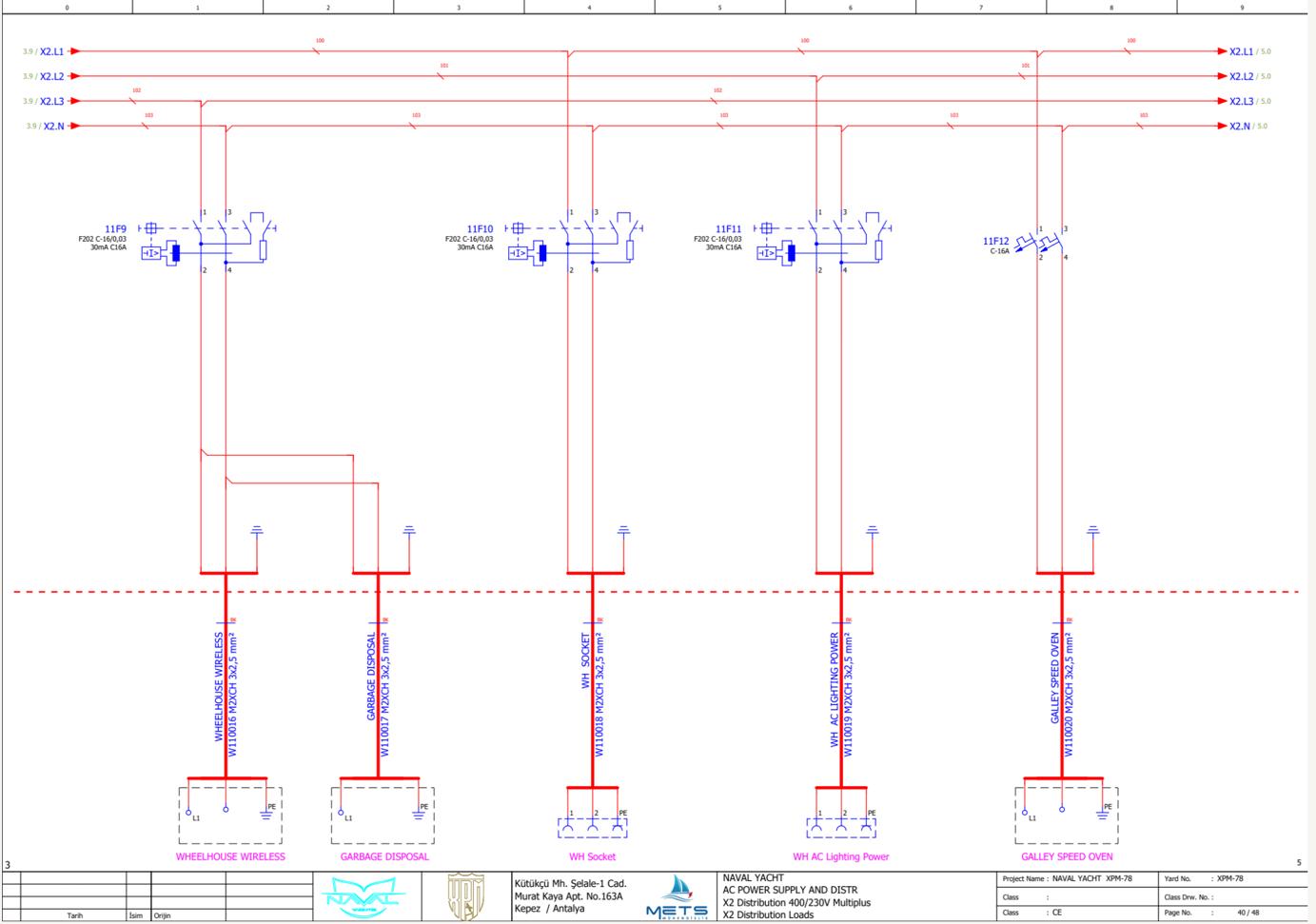
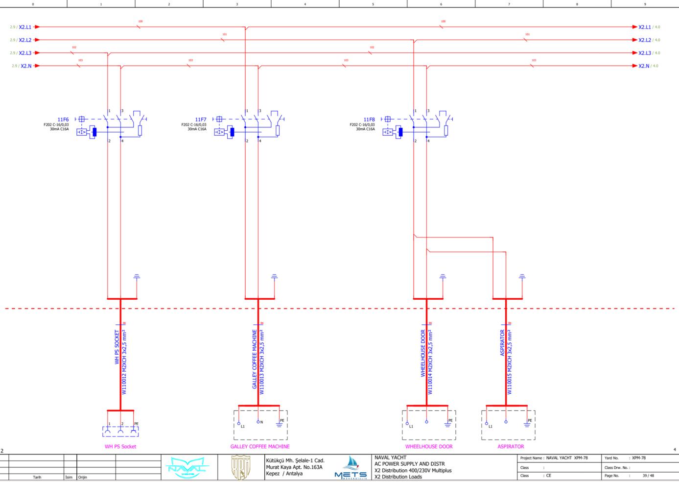
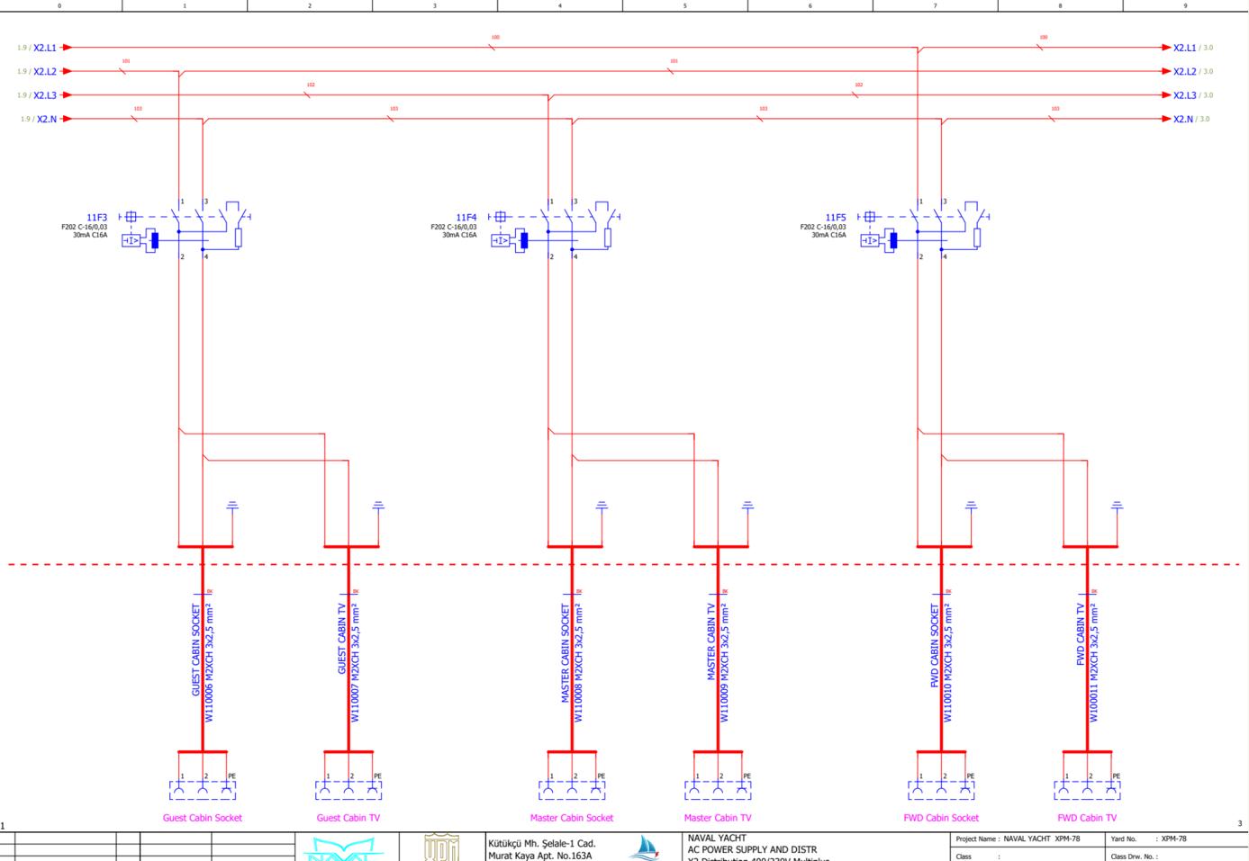
www.
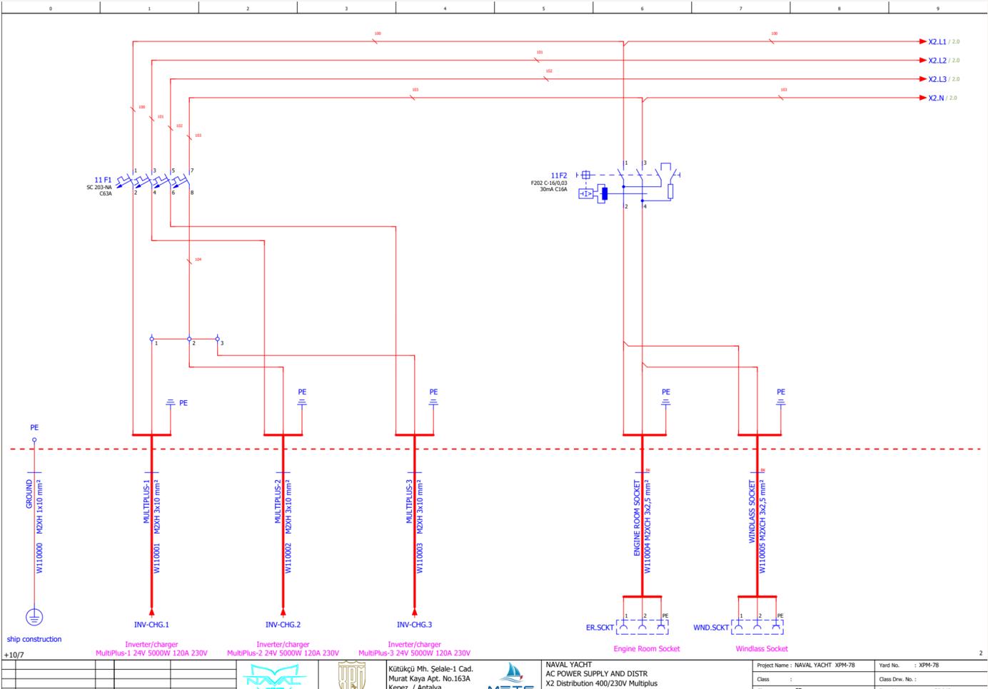
www.Exploreryacht.com for the journey. Page 91 of
14.3 Cabinet X3 – 24VDC Distribution, Single phase Shore Power, Solar MPPT
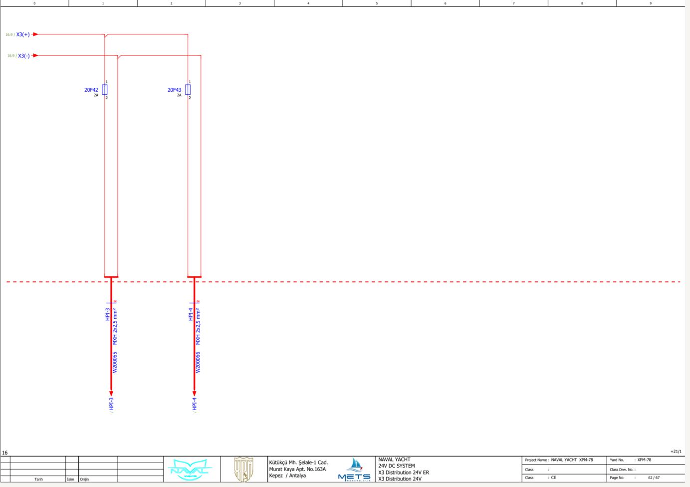
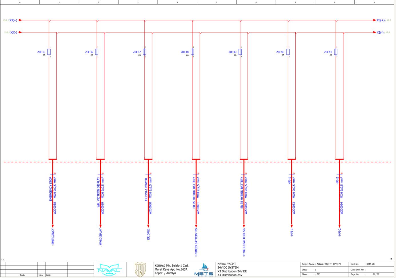
www.Exploreryacht.com for the journey. Page 92 of 102

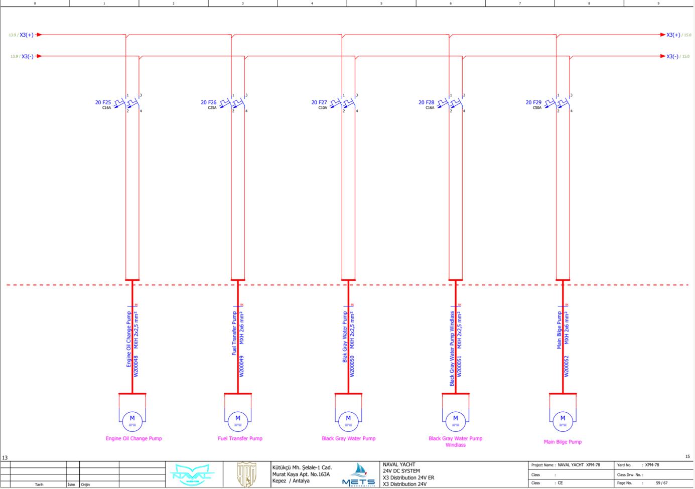
www.Exploreryacht.com for the journey. Page 93 of 102
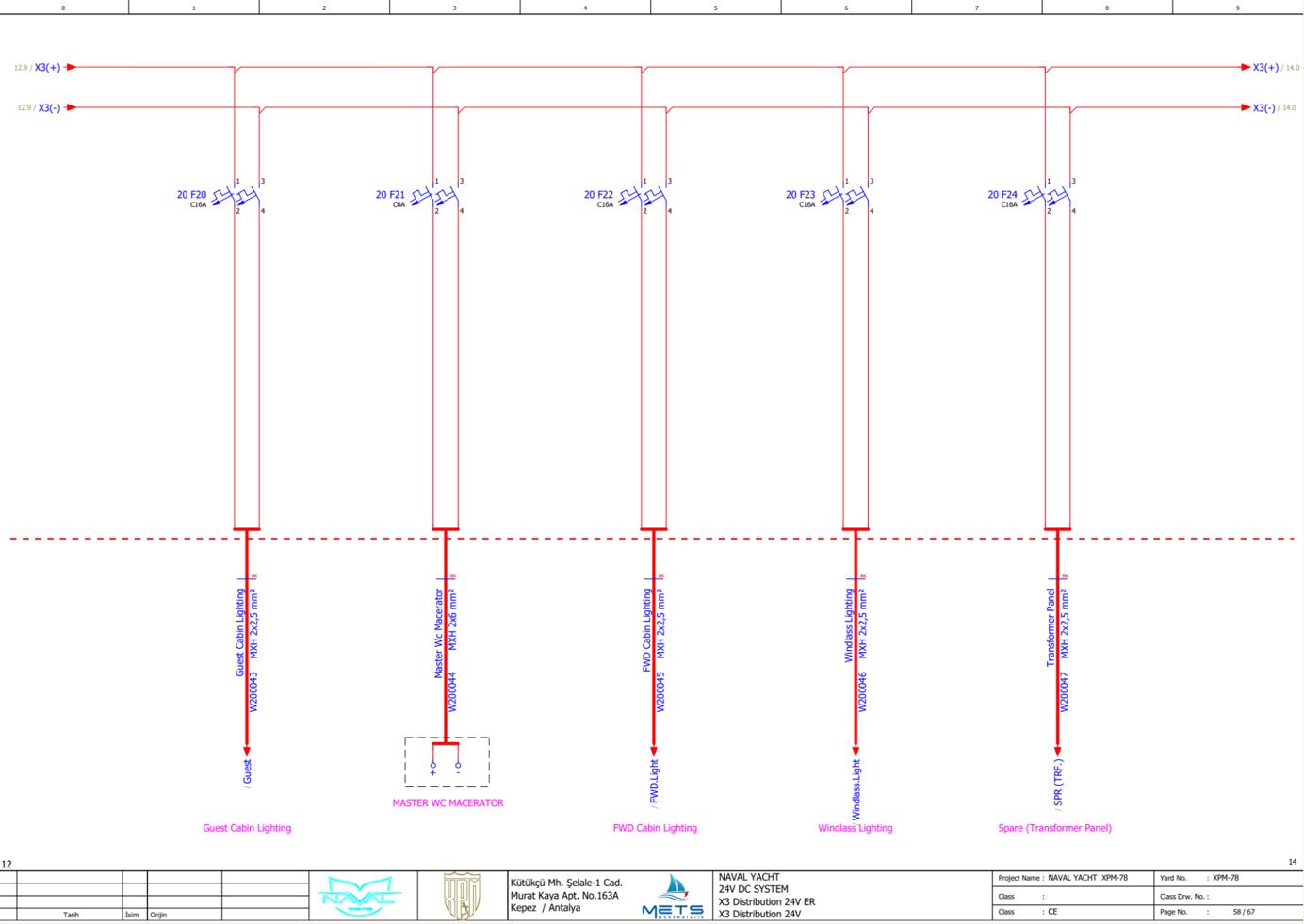
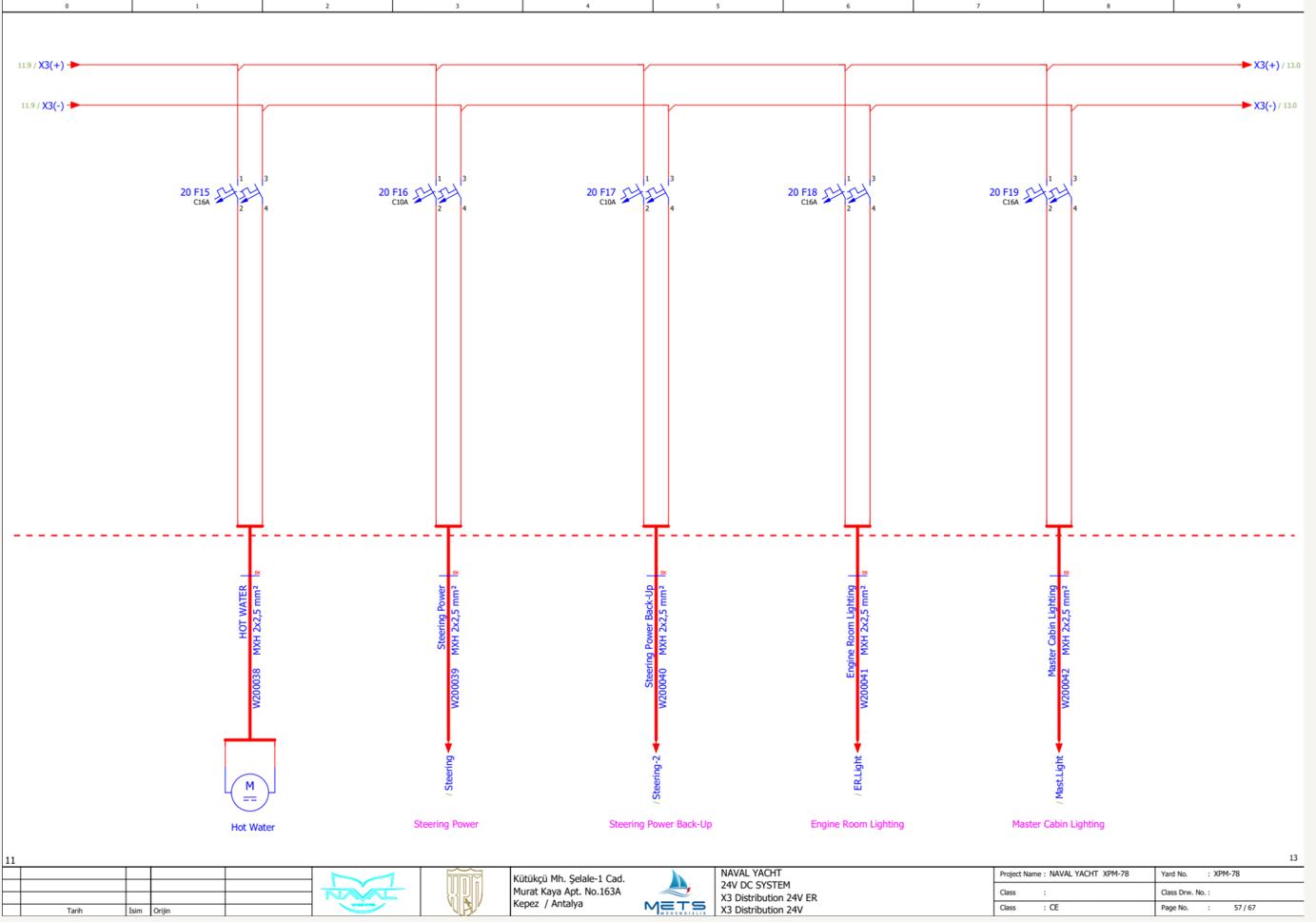
www.Exploreryacht.com for the journey. Page 94 of 102
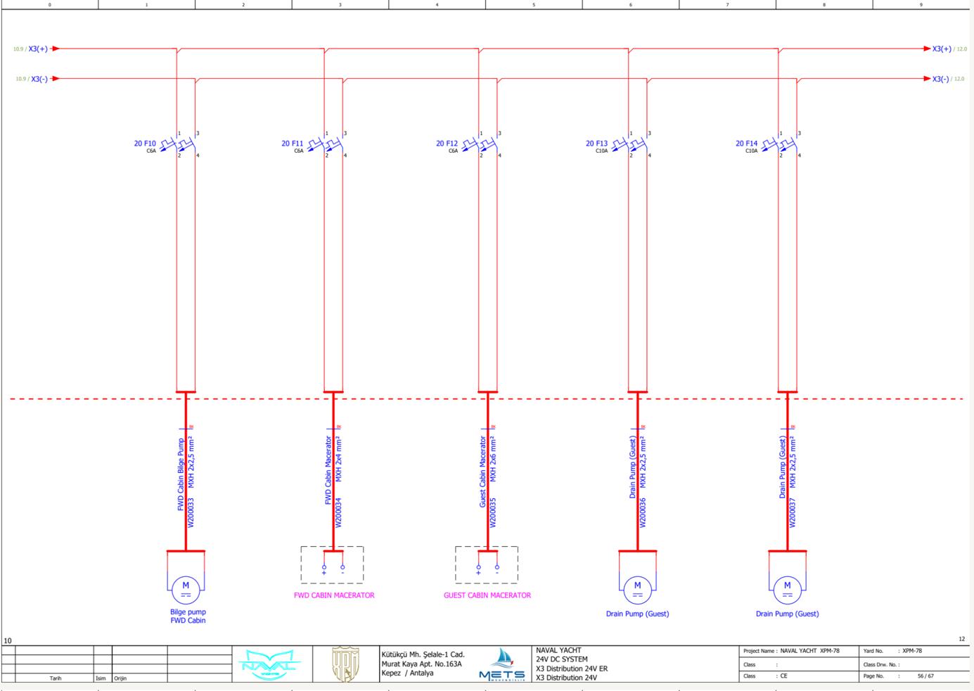
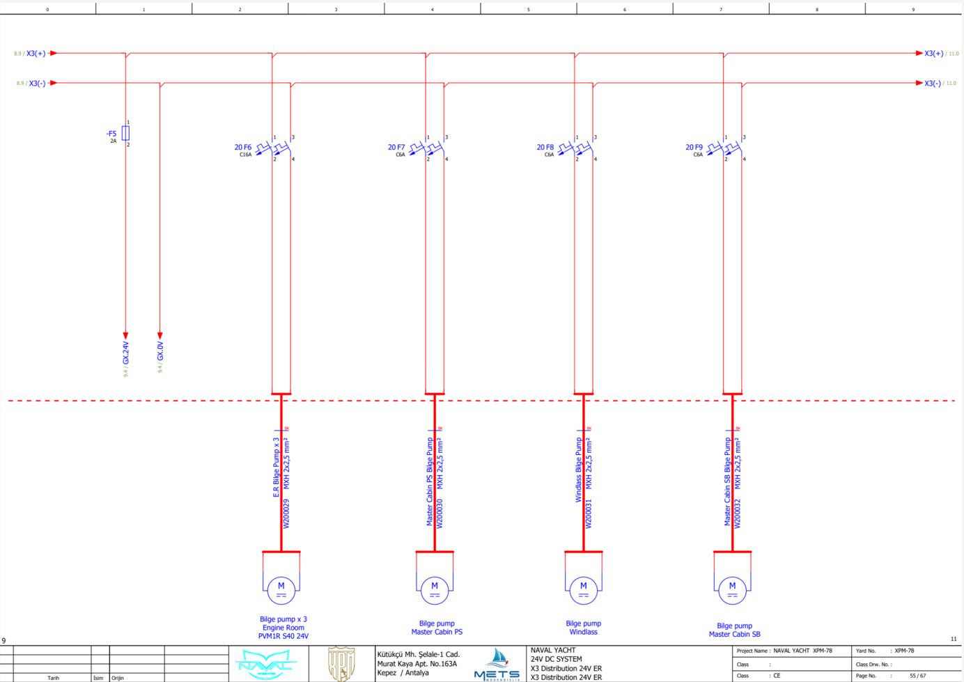
www.Exploreryacht.com for the journey. Page 95 of
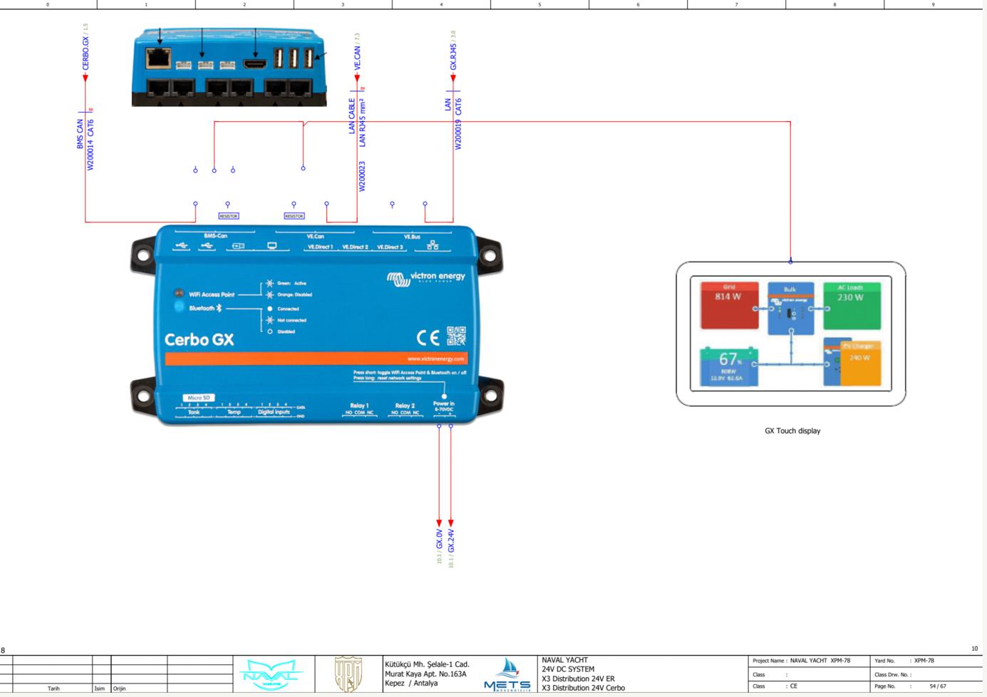
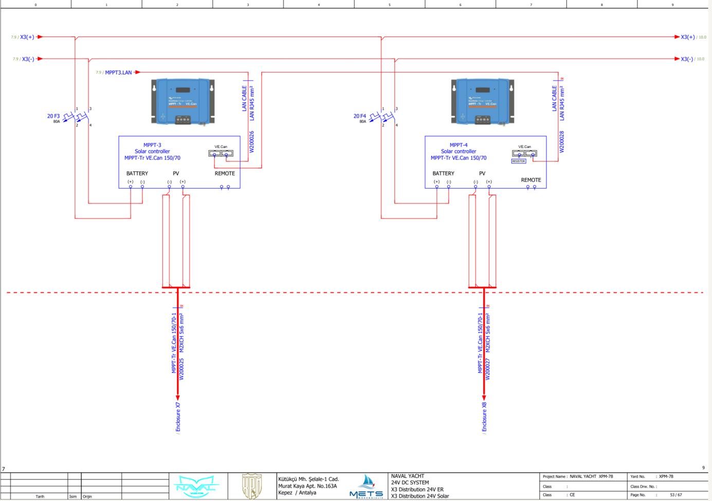
www.
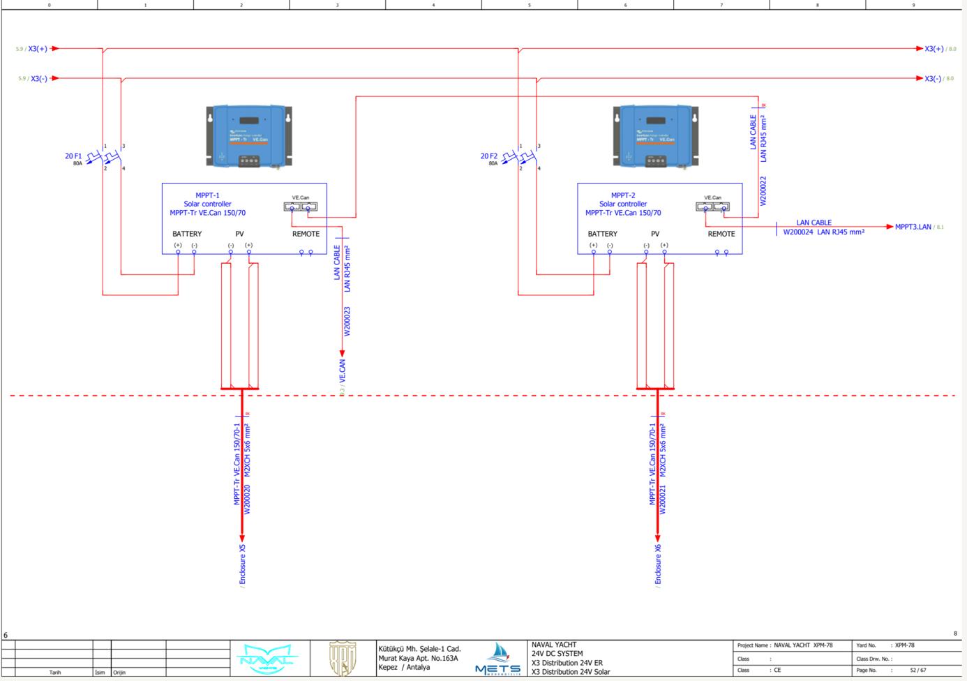
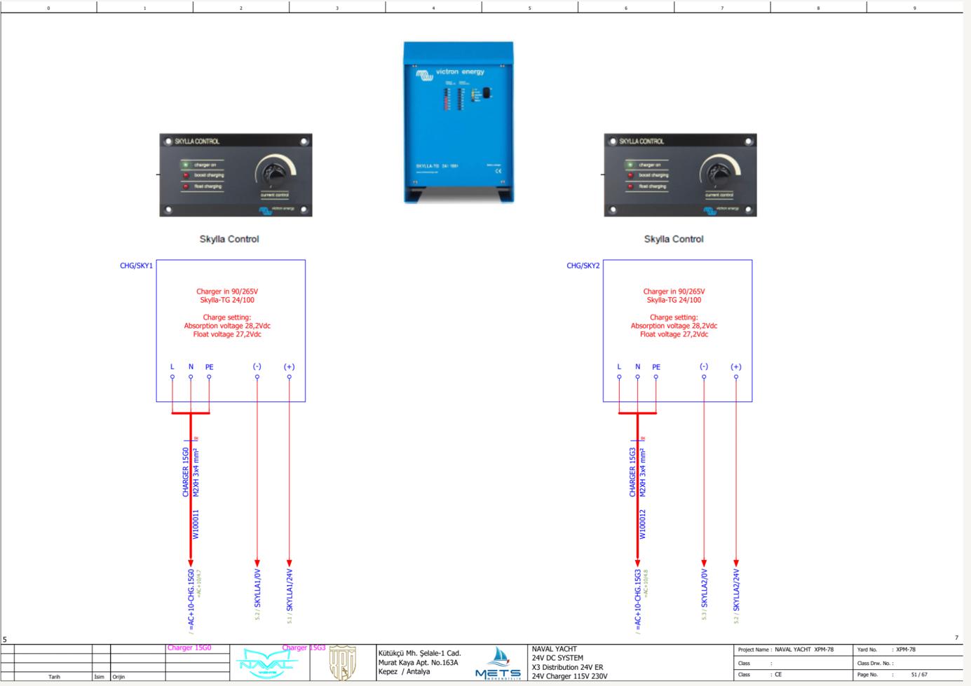
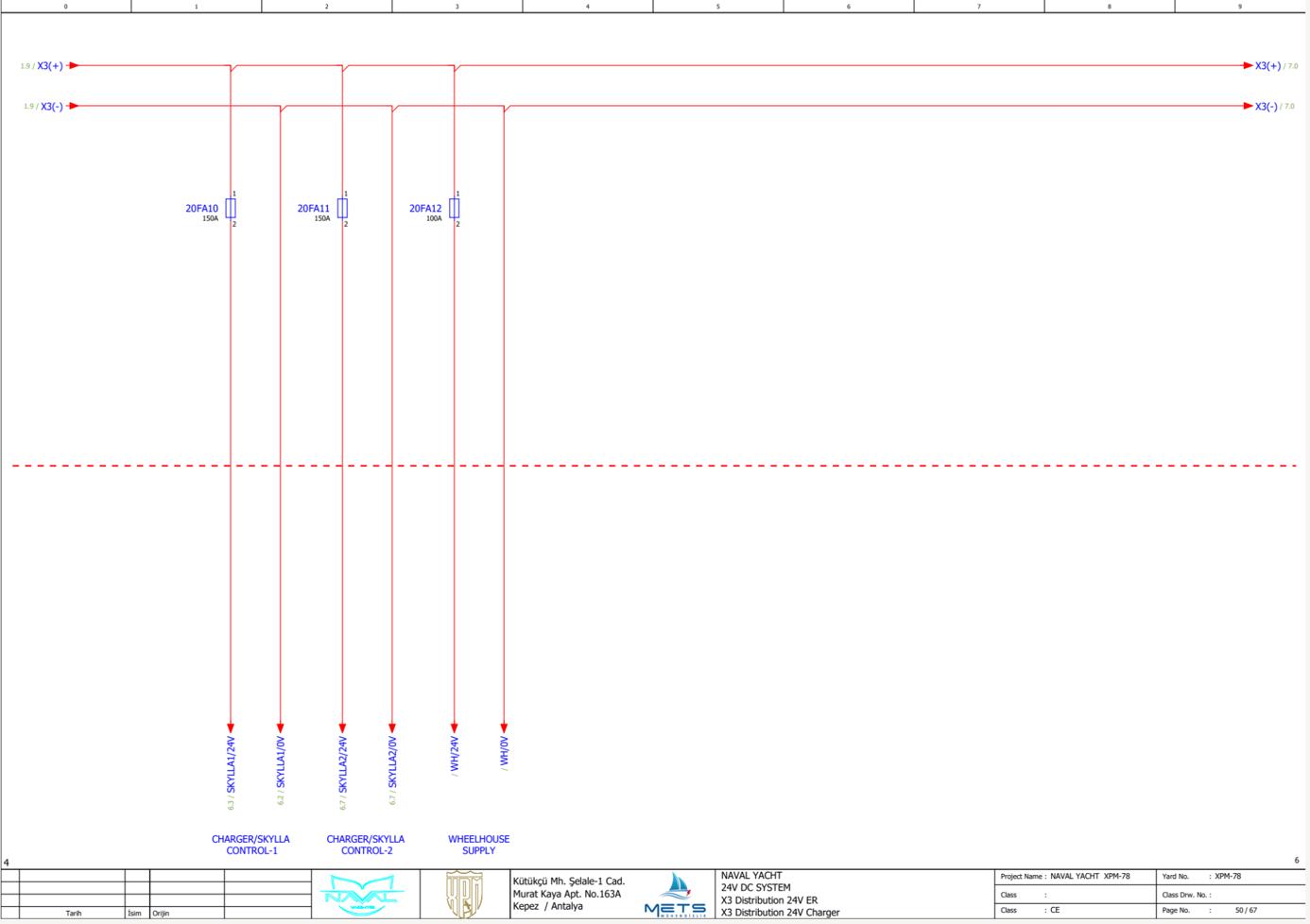
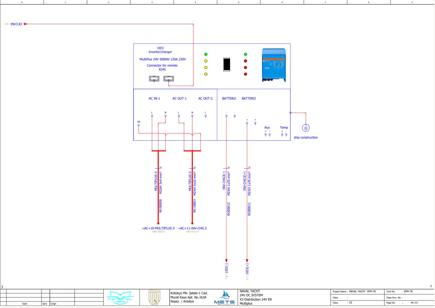
www.Exploreryacht.com for the journey. Page 98 of
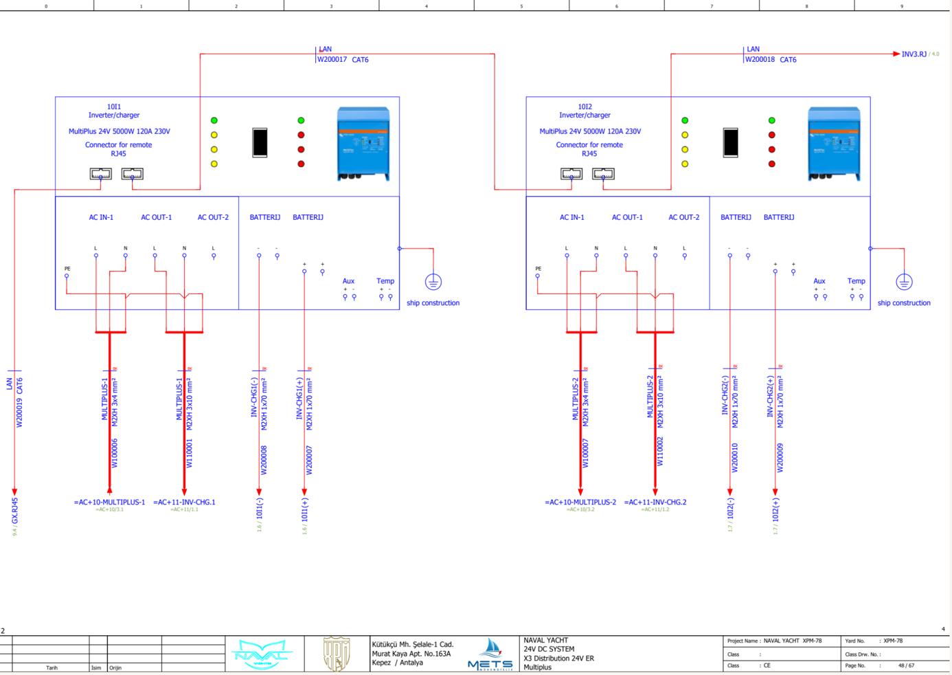
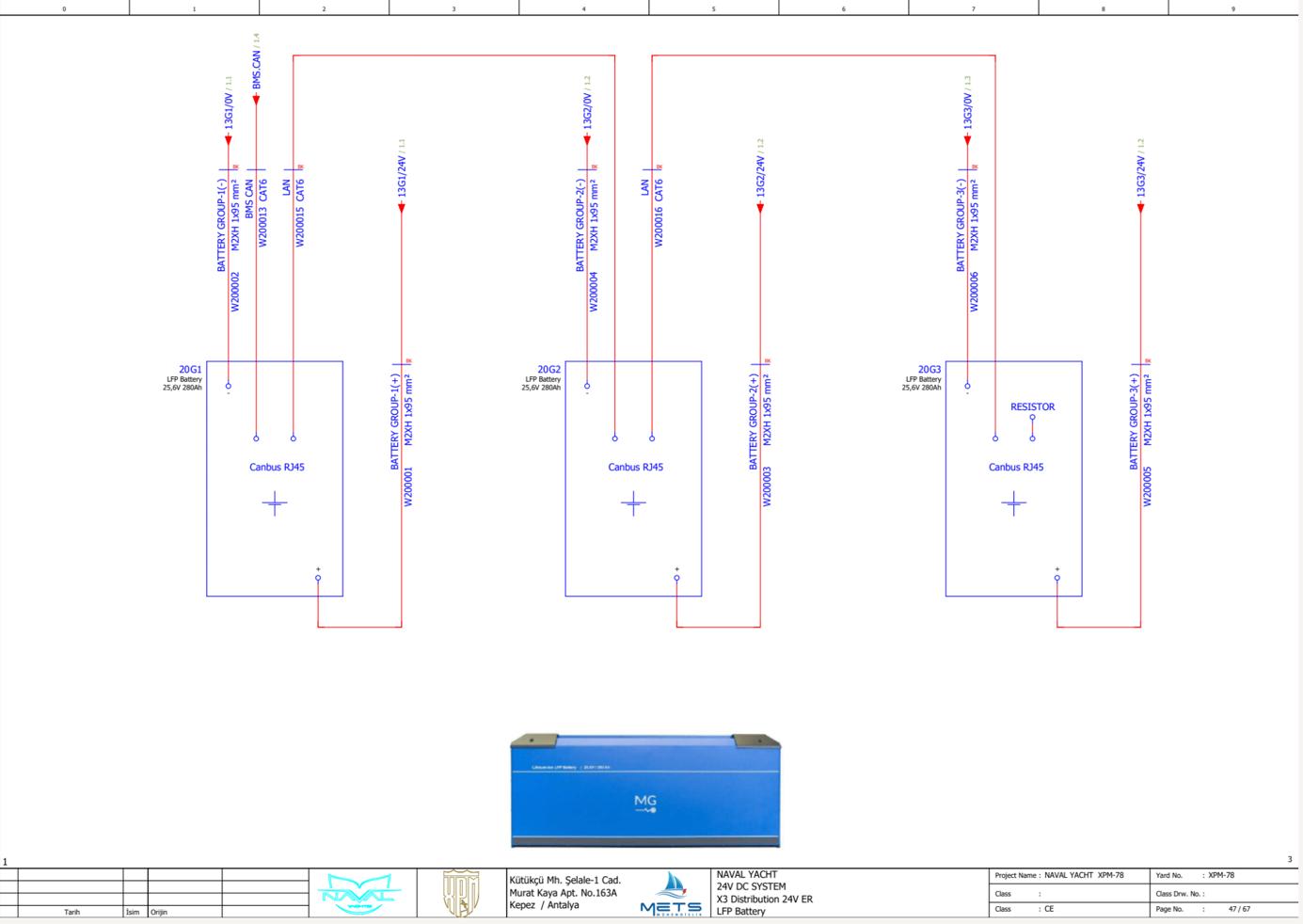

www.
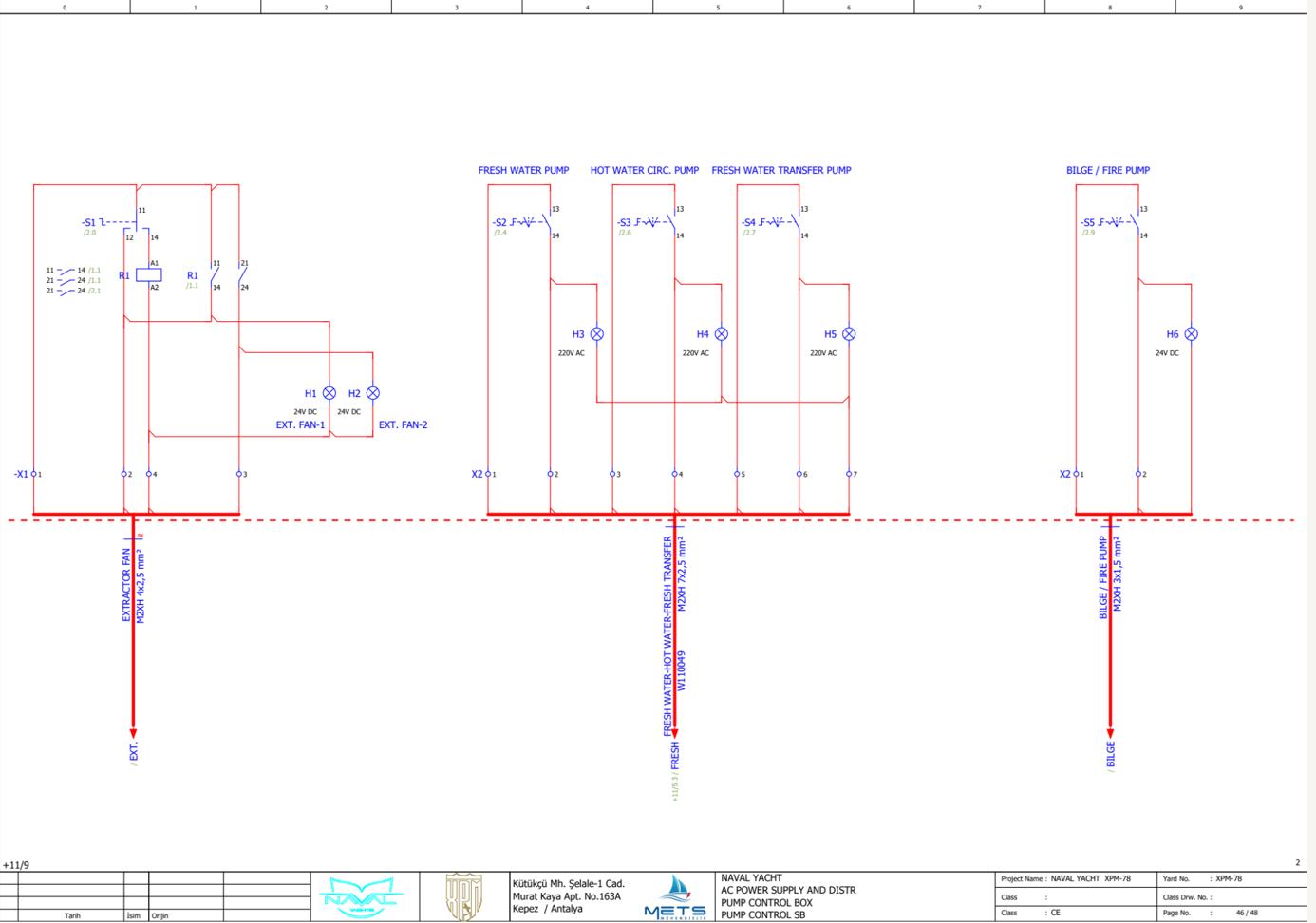
15 DISCLAIMER
The descripMon and specificaMons contained herein were in effect at the Mme this manual was approved for prinMng. Even though care has been taken in the preparaMon of the contents of this owner’s manual, VANGUARD XPM LLC does not assume legal or other liability for any inaccuracy, mistake, misstatement or any other error of whatsoever nature contained herein. VANGUARD XPM LLC formally disclaims liability in respect of such aforesaid ma^ers. The informaMon contained within this owner’s manual of a condensed and general informaMon nature only and your boat can change from the contents.
www.Exploreryacht.com for the journey. Page 102 of 102