

CREW TRAINING MANUAL
1 SUMMARY
The Explorer Yacht Vanguard Crew Training Manual is an extensive guide developed to ensure the safety and efficiency of the crew on board. It provides a comprehensive breakdown of the vessel’s specifications, safety protocols, and operational procedures, designed to comply with UK Marine Coast Guard Agency guidelines. This manual is essential for understanding the structure, equipment, and emergency procedures of the Vanguard yacht, especially focusing on life-saving measures and safe navigation.
�� Safety Procedures: Includes donning lifejackets, launching survival craft, and retrieval methods in case of emergencies like man overboard (MOB).
⚙️Vessel Specifications: Details the main dimensions, performance metrics, engine data, and electrical systems of the yacht.
�� Survival Craft: Comprehensive instructions on the use of lifeboats, sea anchors, and tender operations for safe evacuation and survival.
�� Fire and First Aid: Guidelines on the placement and use of fire extinguishers, first aid kits, and emergency exits.
⚓ Stability and Flooding Risks: Instructions on managing the risk of flooding and ensuring the yacht's stability in adverse conditions.
�� Checklists: Includes checklists for emergency equipment, vessel parts, navigation, anchoring, and mooring, ensuring crew preparedness.
�� Communication Systems: Descriptions of the yacht's VHF, AIS, and EPIRB systems used for navigation and emergency communications.
�� Fire Safety: Key locations for extinguishers, fire blankets, and alarms are highlighted to mitigate fire hazards.
������ Crew Training: Emphasizes the importance of regular drills and familiarity with emergency systems, such as launching life rafts and handling MOB situations.
�� Disclaimer: A legal disclaimer that specifications and procedures in the manual may evolve based on updates or changes made to the vessel.
www.Exploreryacht.com for the journey. Page 3 of 34
2 INTRODUCTION
This manual has been compiled to help you understand your responsibilities as crew or passenger on board M/Y VANGUARD. It has been developed in compliance with UK Marine Coast Guard Agency Guidance Note MGN 280(M), Section 3.11.
A training and instruction manual should contain instructions and information on the life-saving appliances provided in the vessel and contain information on the best methods of survival.
It may take the form of instructions from the manufacturers of the life-saving equipment provided, as a minimum, with the following explained in detail:
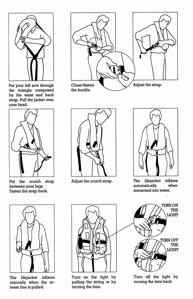
1 donning of lifejackets.
2 boarding, launching, and clearing the survival craft from the vessel.
3 illuminations in launching areas
4 use of all survival equipment
5 use of all aids to location
6 use of sea anchors.
7 recovery of persons from the water;
8 hazards of exposure and the need for warm clothing.
9 best use of the survival craft facilities in order to survive;
10 methods of retrieval, including the use of helicopter rescue gear (slings, baskets, stretchers), breeches-buoy and shore lifesaving apparatus.
11 instructions for emergency repair of the lifesaving appliances.
12 “Personal Survival at Sea” booklet, e.g. MCA Booklet MCA/075
3 GENERAL INFORMATION AND CRAFT DATA
3.1 MANUFACTURER
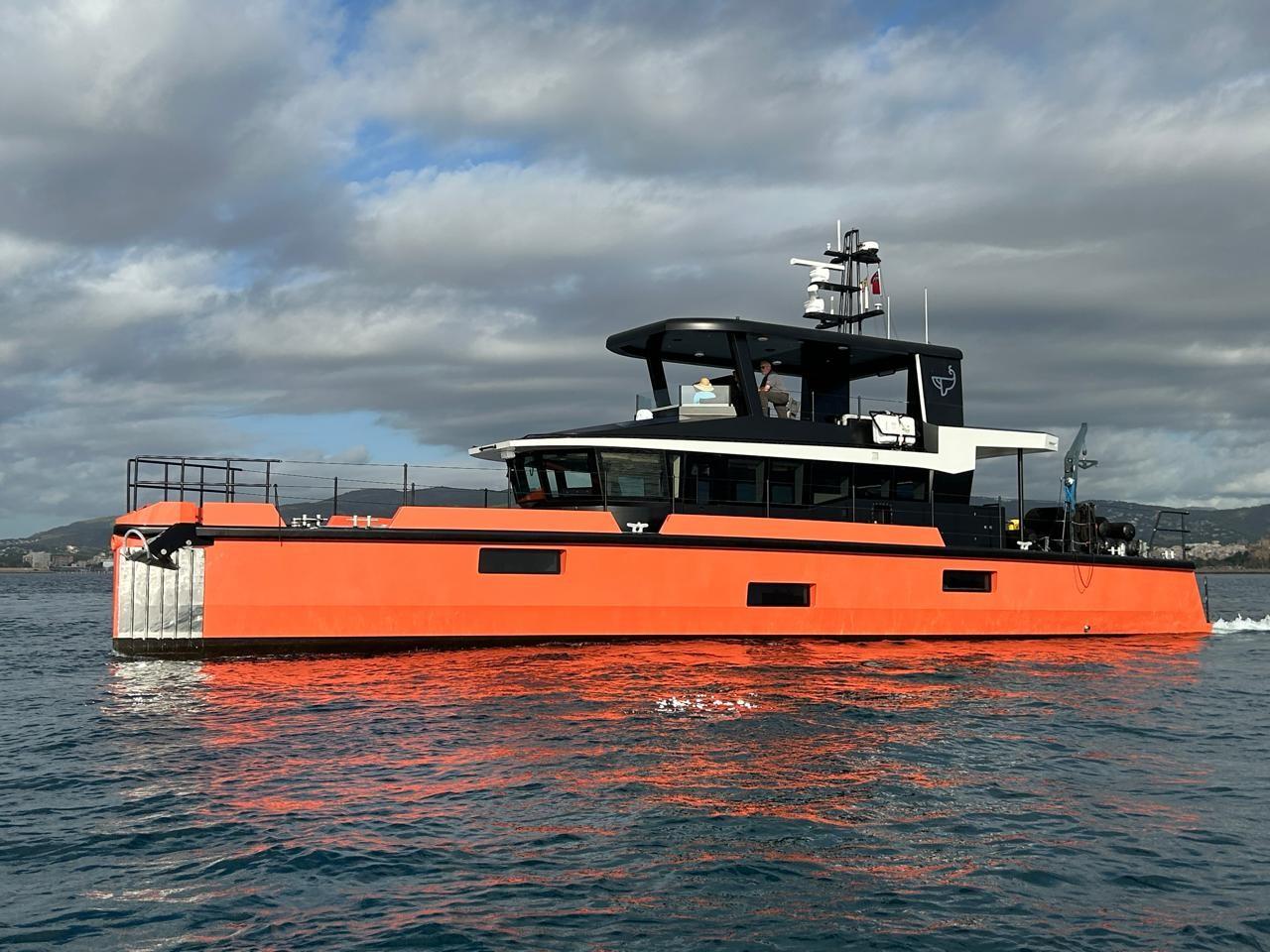
Name of the model (type): VANGUARD Explorer Yacht
Builder/OWNER: VANGUARD XPM LLC
Address: 454 Old Landing Road Bluffton SC 29910, USA
Website: www.exploreryacht.com
Email: chris@exploreryacht.com
Phone: +1 281 630 3513
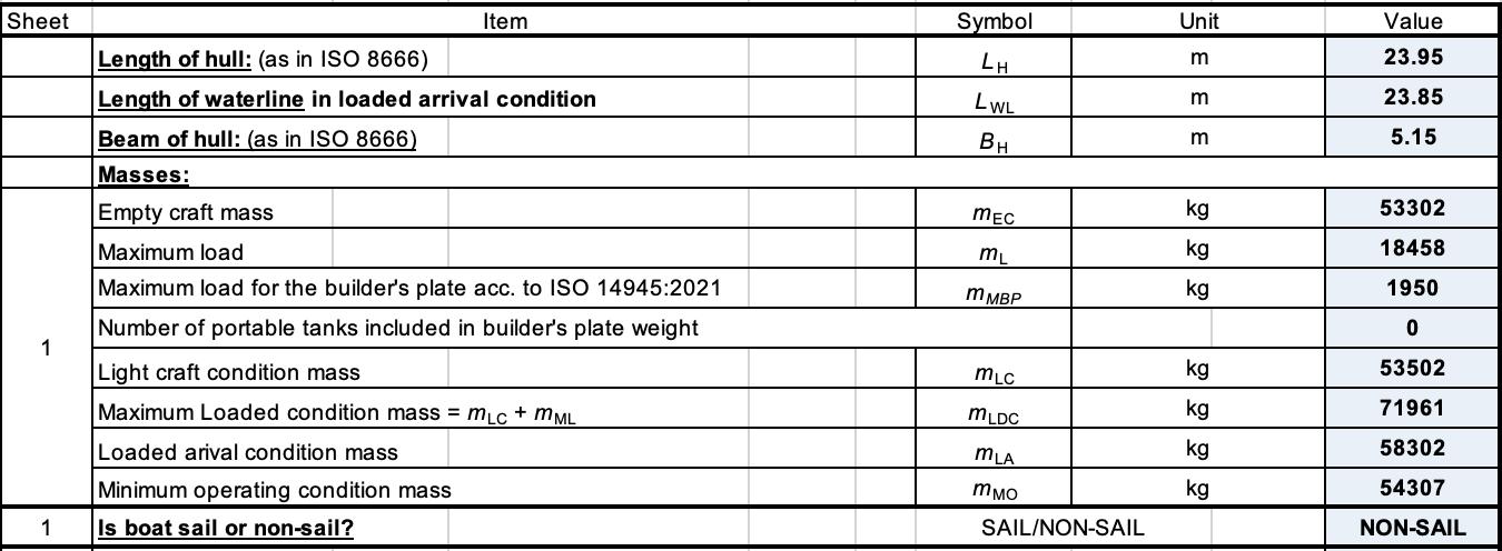
3.2 MAIN DIMENSIONS
3.3 PERFORMANCE
Cruising speed: 7.5/8.0 KN - 1 engine, 8.5/9.5 KN - 2 engines Max Speed: 10.5 KN Range: 3000/3500 NM, 1 engine
Length overall (incl. swimming ladder)
Air Draft
3.4 DRAFTS
Maximum height (air draft), in the light craft condition: 8.15 meter
Maximum draft, in the fully loaded condition: 1.265 meter
3.5 MASS OF THE CRAFT
Light craft condition: 53,502 kg
Maximum load note 1): 15,000 kg +
Maximum load condition mass: 68,000 kg
Note 1) See section loadings
3.6 TANK CAPACITIES
The weight of liquids, when all permanently installed tanks are in DEPARTURE condition, is 15,000 kg.
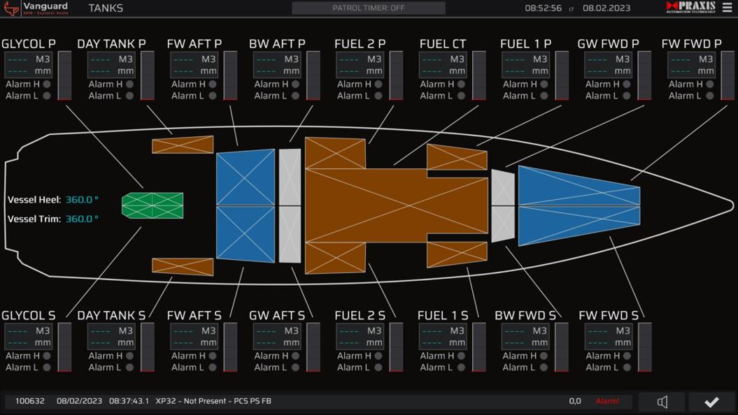
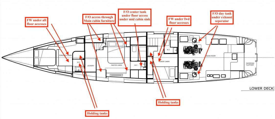
Tank levels are displayed on the Praxis MIMIC displays in the engine room, main helm and flybridge. Levels are measured using BEP Ultrasonic level gauges or Maretron pressure transducers. Locations of the tank gauges are as shown in the attached drawing.
Caution: Not all of the water and fuel tank capacity should be used due to the trim and loading of the vessel. A 20% reserve FUEL should be kept in ARRIVAL condition.
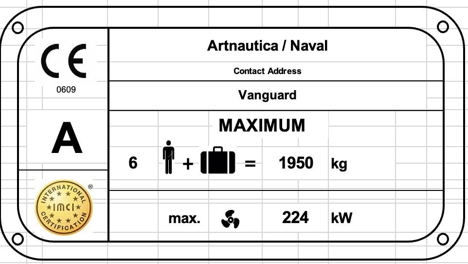
3.7 MAXIMUM RECOMMENDED LOAD
DESCRIPTION
DESIRED
PROVISIONS & PERSONAL EFFECTS
STORES, SPARE GEAR AND CARGO
kg OTHER SMALL BOAT CARRIED
MARGIN FOR FUTURE ADDITIONS
MAXIMUM RECOMMENDED LOAD
COMMENTS
(6 PERSONS)
kg AS SHOWN ON BUILDERS PLATE FUEL IN FIXED TANKS
WATER IN FIXED TANKS
kg (SPECIFIC WEIGHT 0.85 KG/LTR)
kg GREY WATER IN FIXED TANKS 517 kg + MAXIMUM TOTAL LOAD
KG AS USED FOR STABILITY CALCULATION
Warning: When loading the yacht, never exceed the maximum recommended load. Always load the yacht carefully and distribute loads appropriately to maintain design trim approximately level. Avoid placing heavy weights high up.
3.8
ENGINE DATA
Propulsion system:
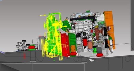
Installed engine power:
Maximum engine power:
3.9 ELECTRICAL DATA
Installed electrical capacity
System:
Shore Power:
3.10
Diesel Electric Hybrid
John Deere 4045 AFM 85 (M1) Diesel
Esco Power PHT 1.4: 1 step up hybrid drive
Twin Disc 2.5:1 step down marine gearbox
Praxis 30/70kW motor /generator
235 kW [320 HP]
116 kW [160 HP, continuous]
2 x 60kW.H power batteries, 2 x 7kW.H house batteries
50 Hz @ 230VAC Single phase, 50Hz 415V AC Three phase
Single Phase 50/60Hz 5kW
Three Phase 50/60Hz, 25KVA
FIRE EXTINGUISHERS AND FIRST AID
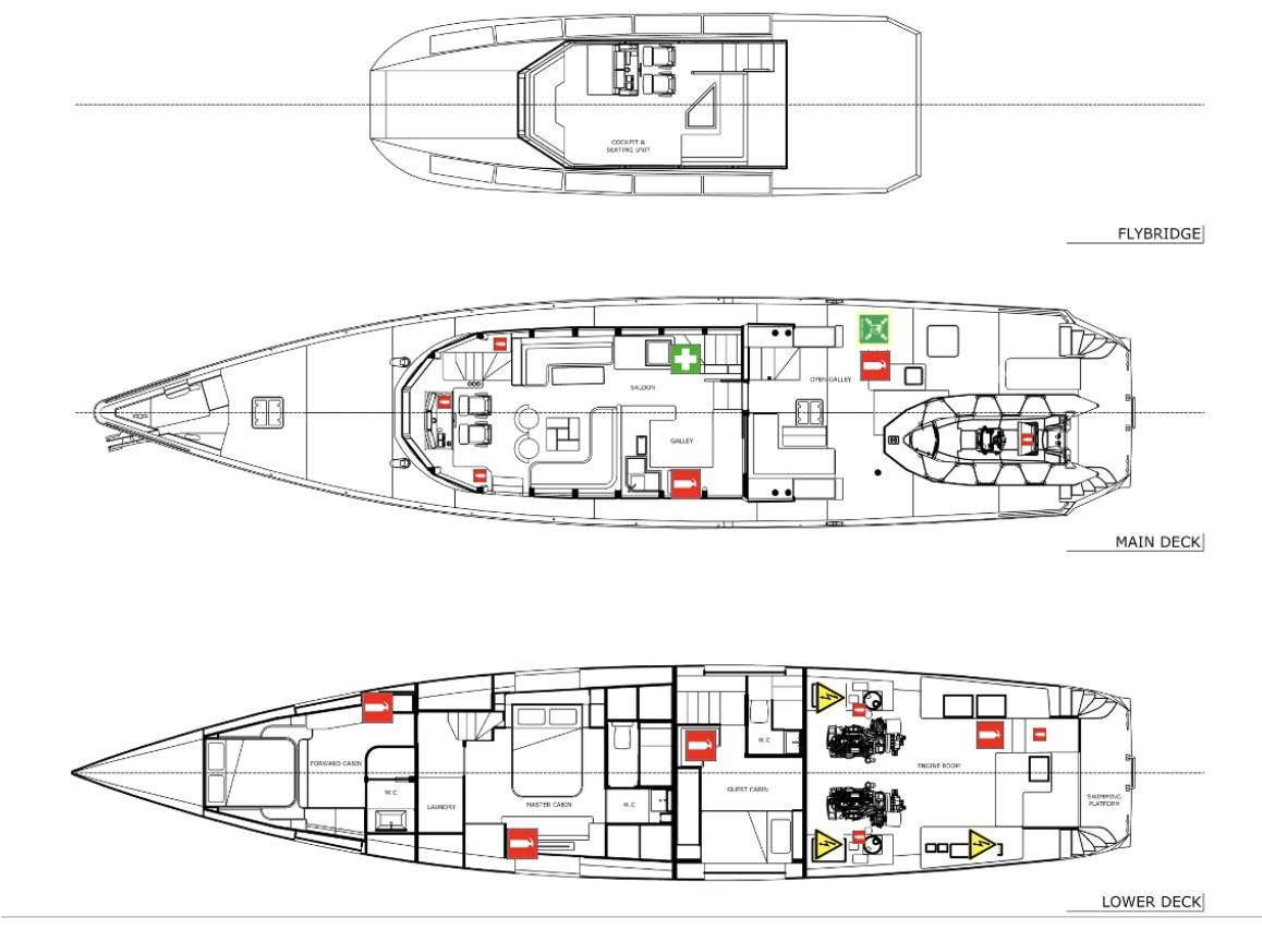
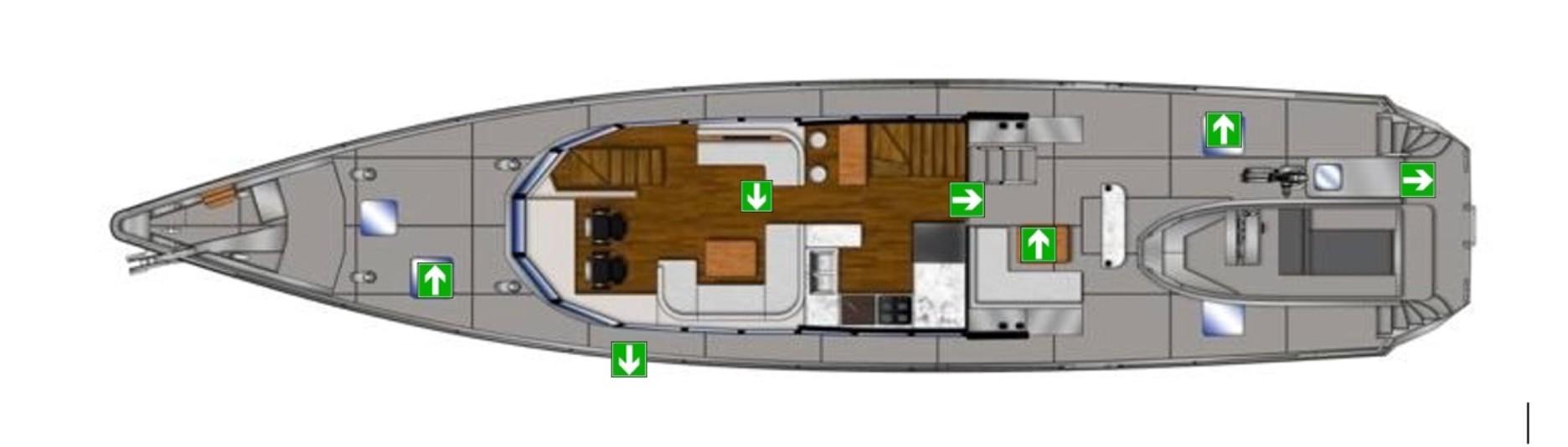
3.11 FIRE ESCAPE EXITS
5 CERTIFICATION & DESIGN CATEGORY
The VANGUARD is certified according to the essential requirements of:
EU Recreational Craft Directive 2013/53/EU
UK MCA Catergory (0) Code as specified in UK MGN 280
As shown on the builders plate for operation in conditions as described for DESIGN CATEGORY A
DESIGN CATEGORY A:
DESIGNED FOR EXTENDED VOYAGES WHERE CONDITIONS MAY EXCEED WIND FORCE 8 (BEAUFORT SCALE) AND SIGNIFICANT WAVE HEIGHTS OF 4 M AND ABOVE BUT EXCLUDING ABNORMAL CONDITIONS, AND VESSELS LARGELY SELF-SUFFICIENT.
DESIGN CATEGORY B:
DESIGNED FOR OFFSHORE VOYAGES WHERE CONDITIONS UP TO, AND INCLUDING, WIND FORCE 8 AND SIGNIFICANT WAVE HEIGHTS UP TO, AND INCLUDING, 4 M MAY BE EXPERIENCED.
DESIGN CATEGORY C:
DESIGNED FOR VOYAGES IN COASTAL WATERS, LARGE BAYS, ESTUARIES, LAKES AND RIVERS WHERE CONDITIONS UP TO, AND INCLUDING, WIND FORCE 6 AND SIGNIFICANT WAVE HEIGHTS UP TO, AND INCLUDING, 2 M MAY BE EXPERIENCED.
DESIGN CATEGORY D:
DESIGNED FOR VOYAGES ON SHELTERED COASTAL WATERS, SMALL BAYS, LAKES, RIVERS AND CANALS WHEN CONDITIONS UP TO, AND INCLUDING, WIND FORCE 4 AND SIGNIFICANT WAVE HEIGHTS UP TO, AND INCLUDING, 0,3 M MAY BE EXPERIENCED, WITH OCCASIONAL WAVES OF 0,5 M MAXIMUM HEIGHT, FOR EXAMPLE FROM PASSING VESSELS.
Note 1 : The significant wave height is the mean height of the highest one-third of the waves, which approximately corresponds to the wave height estimated by an experienced observer. Some waves will be double this height.
Note 2 : VANGUARD was designed and constructed to COMMERCIAL specification under supervision of UK MCA to MCA Catergory (0), Unrestricted navigation to 80 degree N (Summer). A sample of the survey results is available for inspection. Several categories are not in compliance and these represent specific choice of the Owner as the vessel will not be used for commercial purposes. For example a fully compliant medical kit is not carried.
The WIN is fitted on the aft deck above the rear saloon access door O.N.751204, R.T. 34.27 / 100
Warning: Do not exceed the maximum recommended number of persons. Regardless of the number of persons on board, the total weight of persons and equipment must never exceed the maximum recommended load. Always use the seats/seating spaces provided.
Warning: When loading the yacht, never exceed the maximum recommended load. Always load carefully and distribute loads appropriately to maintain design trim approximately level. Avoid placing heavy weights high up.
www.Exploreryacht.com for the journey. Page 12 of 34
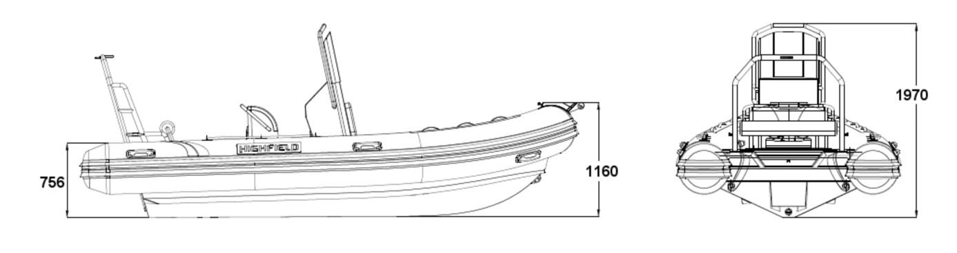
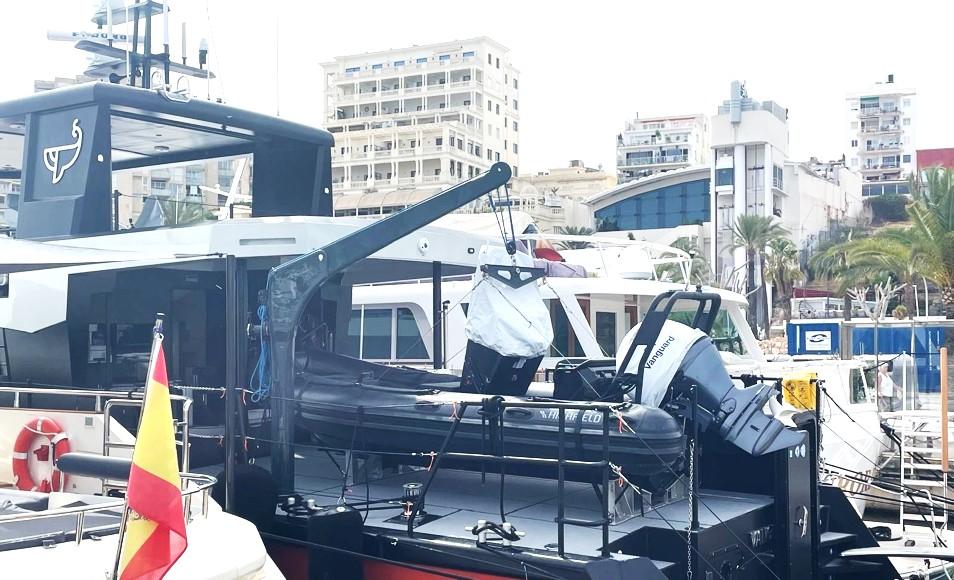
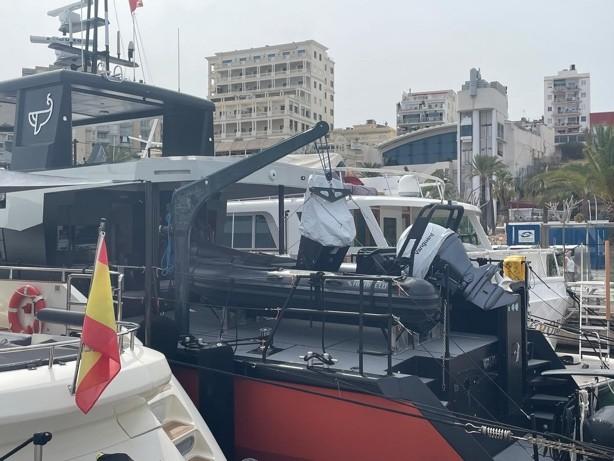
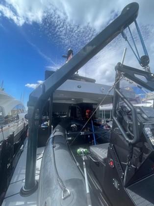
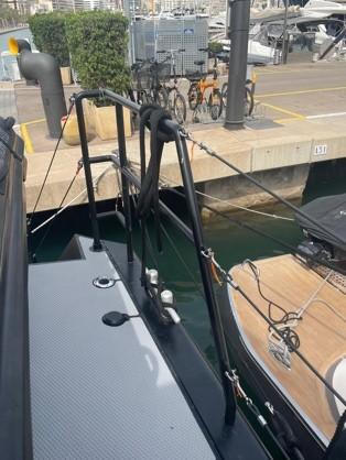
Tender – Tender is launched using the derrick on the Port Aft deck. It can be launched using the electric winch or by hand. Once over the Port side, drop is by gravity, controlled via line tension on the winch drum. The reader is referred to the Operations Manual for further details on launch and retrieval.
Life rafts can be launched by hand from the flybridge, Port of Starboard side. Launching is a process of releasing the retaining strap and catch. The supporting rack will cause the liferaft to fall clear of the cabin roof.
Life rings. Located at the Muster Station, launched by hand.
MOB Sling Located on the Aft Stbd taff rail, launched by hand.
6.3 SURVIVAL EQUIPMENTY
Item N o Description
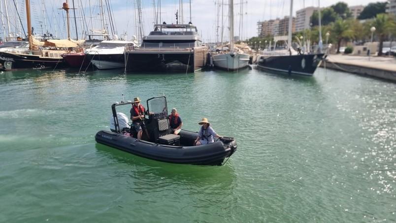
Tender 1 10-man 5M RIB with 100Hp outboard, internal 90l gas tank. Fixed VHF
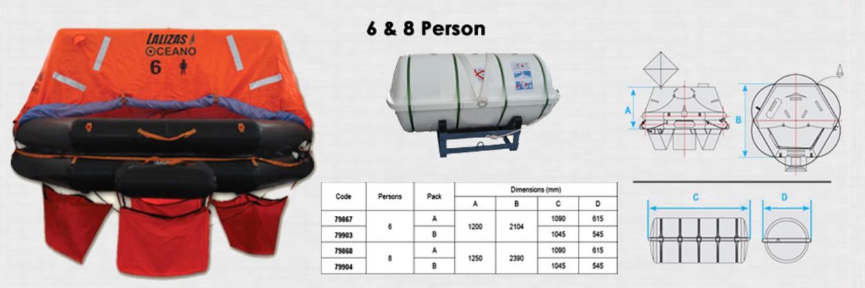
Life rafts 2 8-man SOLAS approved life raft located either side of the aft flybridge seating. They can be launched manually and have a hydrostatic release mechanism.
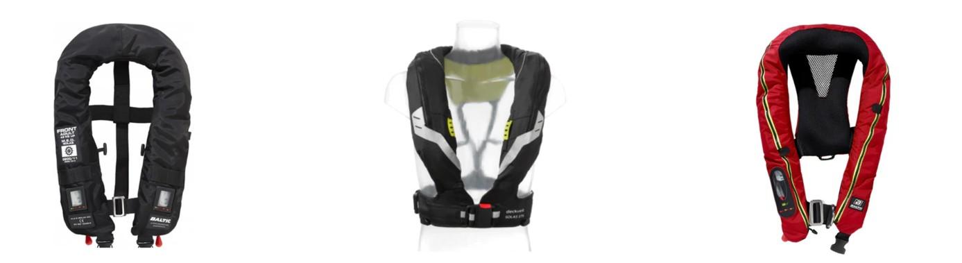
Lifebuoys 2 Lifebuoys located aft of the muster station. Fitted with automatic lights. Lifejackets 6& 2 MED approved self-inflating blue water sailing lifejackets including 2 for persons <32kg
Lifejackets 4 Self-inflating inshore for tender and boat work.
Thermal protective aids None as of yet.
Portable VHF 6 4 by standard, 2 by AIS equipped, locate aft saloon exit.
EPIRB 406MHz 1 Located Stbd life raft area
SART 1 Located aft saloon exit
Pyrotechnics 1
Grab bag for flares Aft Stbd storage locker
Grab Bag 1 Grab bag general Aft Stbd storage locker
Throw lines 2 1 at lifejacket rack, 1 in Stbd aft locker.
General/Fire Alarm 1 Individual heads in all cabins and saloon, control station at main helm.
Training Manual 1 YOU ARE READING IT!
6.4 AIDS TO LOCATION
Item N o
Description
MOB Location on ECDIS V Click on “LIFE RING” image on the side menu of ANY Time Zero display (2 on main helm, one on flybridge, one in Tender). This connects automatically to AIS(A) location system and located the position of the incident.
Life ring Auto Light 2 On life rings, starts automatically on immersion in with water
SART 1 Search And Rescue Transponder - Saloon aft entrance, enhances the return radar signal making the holder easier to see
EPIRB 1 Emergency Position Indicating Radio Beacon - Stbd life ring location on flybridge, transits position via the global search and rescue satellite
journey.
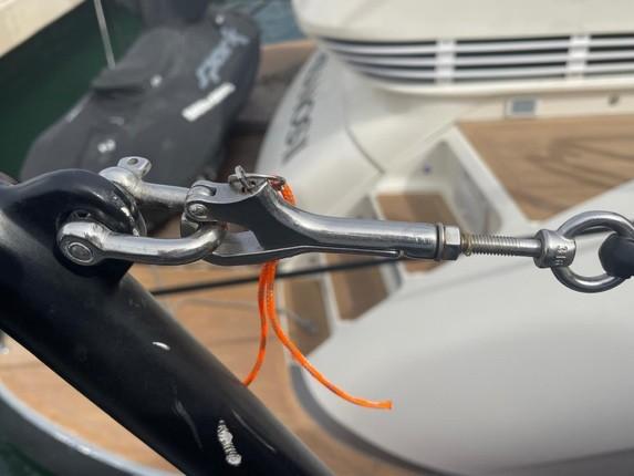
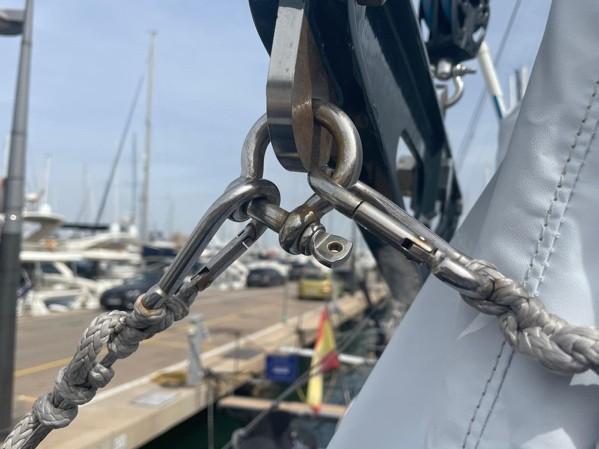
6.5 SEA ANCHORS
Purpose and Function of a Sea Anchor
A sea anchor or a drogue are safety tools used to stabilize a vessel in heavy weather, preventing excessive drifting or broaching. They act by creating drag in the water, slowing the boat's drift and keeping the bow or stern into the wind and waves, depending on deployment. It is good practice to understand their operational use.
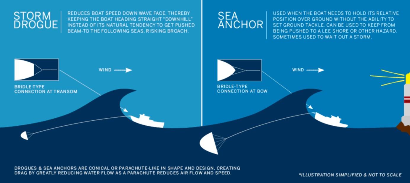
Deployment and Handling
The crew must first secure it to a strong point on the yacht, typically the bow or stern cleats, depending on the intended effect. Bow deployment is preferred for stabilizing the vessel head-on into the wind, minimizing the risk of capsizing. Stern deployment of a drogue will help slow the vessel but still allow passage making. Proper stowage, clear lines, and the use of a trip line (to facilitate retrieval) are important for efficient deployment. During training, crew members should practice deploying in various weather conditions to ensure confidence and familiarity with the procedure.
Inspection and Maintenance
As part of MCA compliance, regular inspection of the sea anchor and associated rigging is mandatory. The sea anchor should be checked for wear and tear, especially the lines and fittings, as these are subject to significant stress when deployed. Training sessions must include a review of maintenance routines, ensuring that the sea anchor is in top condition for emergencies. Ensuring the sea anchor is readily accessible, properly stowed, and inspected regularly is key to maintaining readiness under MCA guidelines.
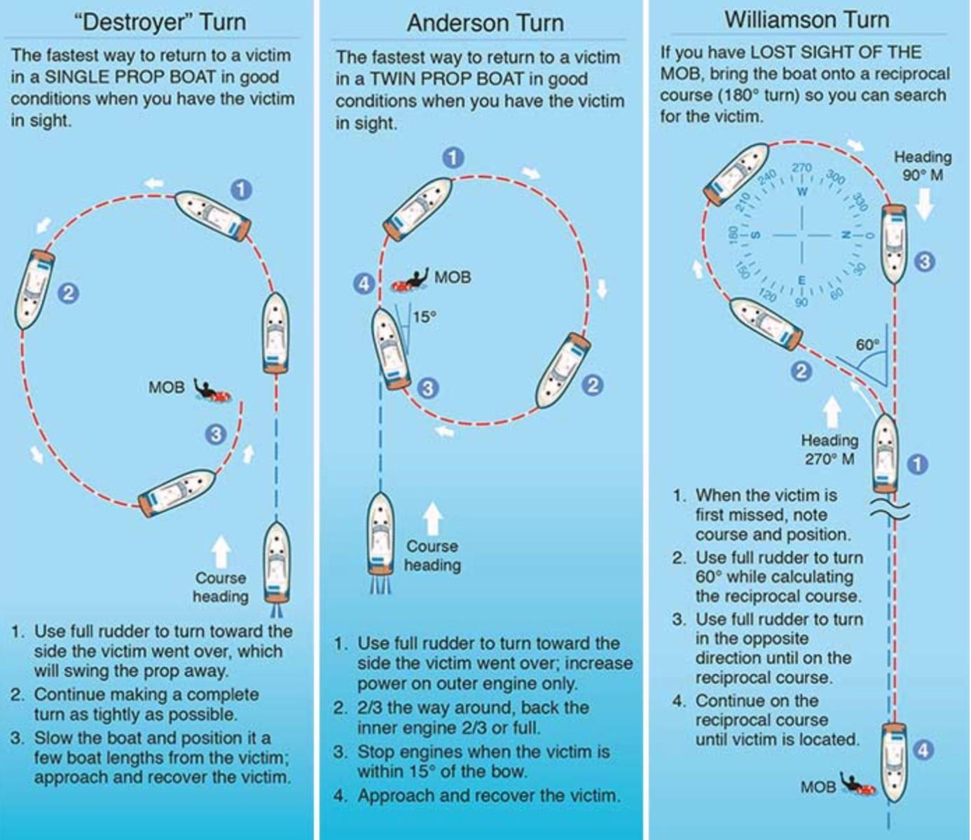
6.6 MAN OVERBOARD (MOB)
In the event of a Man Overboard (MOB), immediate action is critical to ensure the person is retrieved quickly and safely. See also “AIDS TO LOCATION” 5.4, above. The first step is to raise the alarm by shouting "Man Overboard" and noting the person’s location. The vessel should be slowed or stopped, depending on the situation, while a crew member presses the MOB button on the GPS or chart plotter to mark the position. A dedicated lookout must be posted immediately to maintain visual contact with the person in the water at all times. Assigning a specific individual to this task ensures that the victim’s position is continuously tracked, crucial in challenging weather or low-visibility conditions.
Use of the Tender Derrick and Swim Platform
For retrieving the person, the tender derrick (crane) on the Port Aft deck can be effectively used to hoist them from the water, especially if they are unable to climb aboard unaided. The swim platform provides a low, stable access point close to the water, which is ideal for conscious victims to be pulled aboard or for crew members to assist in the recovery. The derrick may be equipped with a lifting sling, allowing the person to be safely hoisted out of the water. The swim platform can also be used as a point of entry for deploying crew members equipped with life jackets or harnesses to assist the victim, if necessary.
MOB Sling and Recovery of an Unconscious Person
A MOB sling (rescue sling) is provided on the Stbd Aft deck rail. The sling should be thrown towards the person, allowing it to be secured around their torso. Once properly secured, the tender derrick can be used to lift the person out of the water without putting further strain on the crew. This method is especially important when dealing with heavy individuals or rough seas, as manual recovery could be unsafe.
6.7 HAZARDS OF EXPOSURE AND WARM CLOTHING
Exposure to the elements poses a significant risk to crew members, particularly on motor yachts under 24 meters, where space for shelter may be limited. Prolonged exposure to wind, rain, and cold can lead to hypothermia, dehydration, and fatigue, severely impairing judgment and physical performance. In UK waters, sudden changes in weather are common, and even mild temperatures can become dangerous when combined with wind chill and wet conditions. Crew members must be aware of the early signs of exposure, such as shivering, numbness, and confusion, and take immediate action to protect themselves.
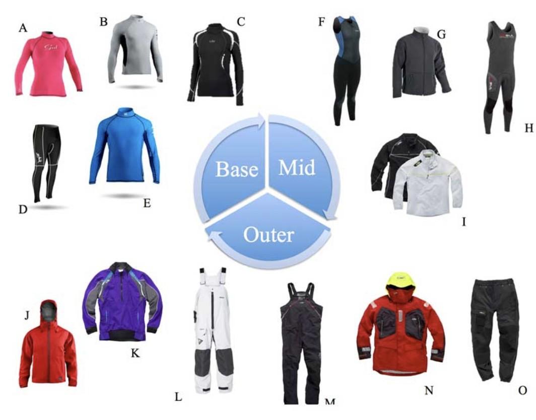
Warm, layered clothing is a critical defense against the hazards of exposure. In accordance with UK MCA inspection standards, crew members should be outfitted with suitable gear that includes thermal underlayers, waterproof outer layers, and insulating mid-layers. Synthetic fabrics and wool are preferable, as they retain warmth even when wet. Additionally, windproof and waterproof jackets, trousers, gloves, and headgear are essential for preventing heat loss. Proper clothing should be accessible at all times, especially when undertaking long shifts on deck or during night watches.
6.8 HEIRACHY OF SURVIVAL CRAFT FACILITIES
Survival craft facilities on a motor yacht under 24 meters are vital to ensuring crew and passenger safety during emergencies. In situations where evacuation is necessary, a clear hierarchy of options— from the yacht itself to the smallest lifesaving devices—guides the decision-making process. Each option varies in capacity, comfort, and durability, so understanding their roles is crucial for both crew and passengers.
Impo rtance of Warm Clothing
The Yacht
The yacht itself remains the primary and best survival option in most emergency situations. With proper maintenance and the right onboard safety equipment, staying aboard the vessel is usually the safest choice, especially if the yacht remains afloat and seaworthy. MCA guidelines emphasize that unless the vessel is in immediate danger of sinking, crew and passengers should first attempt to secure the yacht or wait for rescue while staying onboard, where shelter, communication equipment, and supplies are available.
The Tender
Next in the hierarchy is the yacht’s tender. In situations where the yacht is no longer safe but there is no immediate life-threatening danger, the tender provides a stable and maneuverable means of abandoning ship. As a smaller, powered craft, it offers mobility and can carry multiple people, making it an ideal secondary option for short-term survival or for reaching land or nearby vessels. It also allows for additional communication and retrieval efforts with rescue teams.
Liferafts
Liferafts are the third line of defense when both the yacht and tender are no longer viable. Liferafts are designed specifically for emergencies where immediate evacuation is necessary, such as when the yacht is sinking or in danger of capsizing. These are self-inflating, can accommodate multiple individuals, and provide shelter from the elements. Liferafts must be properly maintained and inspected as per MCA regulations, and crew should be trained in their rapid deployment and use.
Life Rings and Life Jackets
At the base of the hierarchy are personal lifesaving devices like life rings and life jackets. These are the minimum safety measures available and are designed to keep individuals afloat in the water until further rescue options are available. While essential, they do not offer shelter or long-term survival solutions, making them the last-resort option in an emergency. Life jackets and rings should be readily
available, correctly sized, and worn whenever necessary to ensure quick access in dangerous situations.
VANGUARD is fitted with 6 inflatable blue water Lifejackets plus a further 2 for persons (children) under 32kg. These are approved to MCA (DfT) or MED approved (“Wheelmarked”) and comply with BS EN 396 of 150N or BS EN 399 of 275N or equivalent ISO/CEN standard. Additionally, a further 4 inflatable lifejackets are provided for inshore work and general use on the Tender.
Understanding this hierarchy of survival craft—from the yacht itself down to individual life-saving devices—ensures that in any emergency, the most effective and safe options are prioritized.
6.9 RETRIEVAL AND RESCUE
When it comes to retrieval operations aboard a motor yacht under 24 meters, the focus is on swift, efficient, and safe recovery of individuals who are overboard or in distress. Different choices are available depending on the situation and the resources availabl. Onboard, equipment like MOB (man overboard) slings, recovery harnesses and lifejacket lift points allow for a direct and secure method of retrieving a person from the water. If the person is unconscious or injured, lifting gear such as a tender derrick can be used to hoist them aboard safely, minimizing additional risk to crew members. For the most serious situations, lifeboats, coastguard and helicopter rescue are the final options.
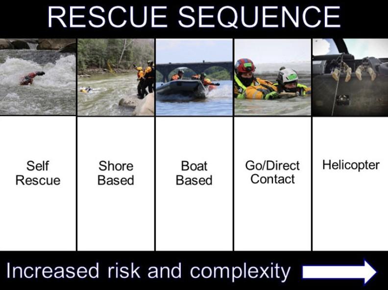
Helicopter Rescue Gear
In more severe situations where helicopter assistance is required, yachts must be prepared for the use of helicopter rescue gear, including slings, baskets, and stretchers. A rescue sling allows for quick and effective retrieval of conscious individuals, while rescue baskets and stretchers are used for the injured or unconscious. When preparing for helicopter operations, the crew must ensure that the deck is clear of obstructions and that the yacht maintains a steady heading as instructed by the rescue crew to assist with safe hoist operations. The crew should be familiar with communicating with rescue teams, using hand signals or radio communication to coordinate the safe transfer of individuals to the helicopter.
Breeches Buoy System
The breeches-buoy is a traditional rescue system still in use today, especially in shore-based rescue operations. This method involves a pulley system where a buoy with leg harnesses is sent across a line from the yacht to shore or another vessel. It can be a lifeline when more modern retrieval options aren’t feasible, such as in heavy surf or near cliffs. While less common for smaller motor yachts, being familiar with the system is crucial, particularly when operating in remote or rugged coastal waters. Crew members should be trained on setting up and operating the breeches-buoy apparatus in case they find themselves in a scenario where more conventional rescue equipment is unavailable.
Shore-Based Lifesaving Apparatus
Shore-based lifesaving apparatuses are often used when the yacht is in proximity to a coastline, and external assistance can be provided from land. These systems typically consist of a line-throwing device, lifebuoys, and rescue ropes that can be deployed from the shore to the vessel or to individuals in distress. Understanding how to cooperate with shore-based rescue teams is vital for the yacht’s crew, as they might need to stabilize the vessel or assist in connecting lines. MCA regulations require motor yachts to be aware of local shore-based lifesaving capabilities and train crew members in collaborating effectively during such operations, ensuring seamless coordination between yacht crew and shore-based rescuers.
6.10 LEE CLOTHS (MGN 280)
MGN 280 requirements dictate that 50% of the bunks on board are to be provided with Lee Cloths to allow crew to get sleep in rough weather. These are for the aft cabin and stored in the forward upper locker, Same location as the HVAC controls.
6.11 REPAIR OF LIFESAVING APPLIANCES
The proper functioning of lifesaving appliances (LSAs) such as life rafts, life jackets, EPIRBs, and flares is critical. Routine inspections must be conducted regularly, to ensure that all equipment is fully operational and compliant with MCA standards.
Inspection and certification of lifesaving appliances is recorded in the vessel maintenance software package
Repair and Replacement Protocols
When lifesaving appliances are found to be faulty or nearing their expiration, immediate repair or replacement is required to remain within MCA certification guidelines. Items like life rafts, HRUs, or life jackets must be replaced following any service life limits or if inspection reveals wear, degradation, or malfunction.
6.12 LAUNCHING THE TENDER
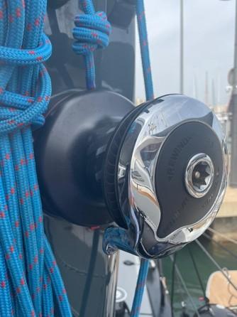
VANGUARD is equipped with a 5.0m Highfield RIB itself fitted with a 100hp Yamaha outboard motor. The tender is stowed on the aft deck. It is launched and retrieved using a 1500 SWL derrick from FEM equipped with a two way Harken winch. The winch can be operated electrically or manually.
Launching the tender is a 2-crew operation. One crew working the winch and the other the securing lines allowing the tender to be swung outboard and back inboard to the deck chocks.
Launching the tender
Stop VANGUARD in calm weather and allow her to come to rest.
Remove the Port aft railing bar clipping the lines Fwd and Aft using the attached pelican clips. Remove the aft deck Port rail and stow on deck.
Release the derrick line and flake for use.
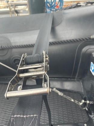
Release the four retaining cargo straps that hold the tender to the chocks.
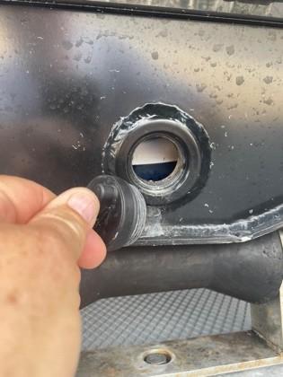
Install the transom drain plug.
The tender is now ready to lift.
Move all additional personal to the Stbd side of VANGUARD and forewarn them there will be an approximately 5 degree Port list until; the tender is in the water.
Raise the tender to the maximum lift. Swing the stern out and over the side allowing eh bow to rotate aft facing the opposite way to the hull of VANGUARD.
Using line friction, release the tender line until it is floating under her own buoyancy. Vanguard will return to a level trim
Attach bow and stern lines to VANGUARD.
One crew member (with Life Jacket) can drop down in to the tender, turn on battery, attach kill cord, lower and start engine, turn on VHF and MFD Nav system.
After the engine is running, release the spreader retaining cleats.
The tender is now ready for use.
Replace Port aft railing and re-attach lines.
7 INFORMATION REGARDING RISK OF FLOODING AND STABILITY
7.1 STABILITY DATA FOR SAILING & MOTOR YACHTS
Compliance with the stability criteria does not ensure immunity against capsizing regardless of the circumstances or absolve the owner of the yacht from his responsibilities. Therefore exercise prudence and good seamanship having regard to the season of the year, experience of the crew, weather forecasts and navigational zone, and should take appropriate action as to speed, course and sail setting warranted by the prevailing conditions.
Before a voyage commences care should be taken to ensure that sizeable items of equipment have been properly stowed to minimise the possibility of both longitudinal and transverse shifting under the effect of accelerations caused by pitching and rolling. In adverse weather conditions and when there is the possibility of encountering a severe gust, squall or large breaking wave, all exposed doors, hatches, skylights, vents, etc. should be closed and securely fastened to prevent ingress of water.
Stability recommendations:
- All crew members need to be adequately trained.
- Any change in the disposition of the masses aboard (for example the addition of a fishing tower, radar, a stowing mast, change of engine, etc.) may significantly affect the stability, trim and performance of the boat;
- Stability is reduced by any weight added high up of slack bilges;
- In rough weather, hatches and lockers should be closed to minimize the risk of flooding;
- Stability may be reduced when towing or lifting heavy weights using a davit or boom;
- Breaking waves are a serious stability hazard.
7.2 SIGNIFICANT STABILITY INFORMATION
Downflooding Angle 58 degrees (limited by engine room ventillation openings)
Maximum Righting Moment @ 45 degrees
Angle of Vanishing Stabilitty >>70 degrees
Caution: Before leaving the harbour please make sure that engine room exterior hatch, deck hatches, the salon rear hatch and pantograph doorclosed.
7.3 LOCATION OF THROUGH HULL FITTINGS.
The drawing added to this manual below show all through hull fittings installed in the hull.
All overboard discharge through hull fittings extend above the waterline and can be maintained afloat.
Main sea suction fittings are equipped with shut off butterfly valves and fully redundant for maintenance at sea.
Familiarize yourself with the location of this through hull fittings and inform your crew before leaving the harbor. In case of an emmergency these seacocks should be found easily.

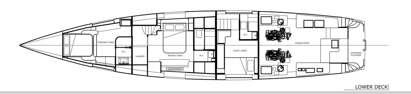

7.4


Location of through hull overboard discharge fitting
Location of through hull sea suction
WATERTIGHT CLOSURES
The following openings are marked as “WATERTIGHT CLOSURE – KEEP SHUT WHEN UNDERWAY”:


Location of watertight doors. Note: Pantograph door fitted with a washboard for use at sea.
Location of watertight hatches. Note: FOREPEAK & SWIM PLATFORM MUST BE CLOSED at sea.
Caution: Keep port lights, windows, washboards, doors, hatches or ventilation openings closed when appropriate, e.g. in rough weather.
8 CHECKLISTS, PLANS, SYMBOLS & WARNINGS
8.1 Emergency Equipment
Item Description
Lifejackets (inc Lights & Whistles)
Flares
Grab Bag
EPIRB (Emergency Position Indicating Radio Beacon)
SART (Search and Rescue Transponder)
Handheld VHF
Immersion Suits
Fire Extinguishers
Fire Blanket
Fire Detection System
Bilge Pumps (Electric and Manual)
First Aid Kit
Lifebuoys with Lights/Smoke
Liferaft
Man Overboard (MOB) Recovery Equipment
Fire Hoses and Pumps
Emergency Steering
Thermal Protective Aids
SOLAS-approved lifejackets with lights and whistles for each person onboard.
SOLAS-approved flares, including parachute rockets, hand flares, and smoke signals.
Waterproof bag containing emergency supplies (EPIRB, spare flares, handheld VHF, first aid kit, food, water, etc.).
406 MHz beacon to signal distress and provide location to search and rescue authorities.
Radar transponder for locating the yacht during a rescue operation.
Portable VHF radio for emergency communication if primary systems fail.
SOLAS-approved thermal immersion suits to protect against cold water exposure.
Properly serviced fire extinguishers located in key areas (galley, engine room, cabins).
Fire blanket stored near the galley or other highrisk areas.
Smoke and heat detectors throughout the yacht, connected to alarms.
Electric bilge pumps with automatic activation, plus manual pumps for backup.
Fully stocked first aid kit, including supplies for treating burns, wounds, and hypothermia.
Lifebuoys equipped with automatic lights and smoke markers for man overboard situations.
Liferaft sized for the number of crew onboard, with emergency rations and signaling gear.
MOB retrieval systems, including rescue slings or ladders.
Fire hoses connected to the yacht’s fire pumps, tested regularly.
Instructions and gear for operating the yacht’s emergency tiller or other emergency steering systems.
Thermal blankets and survival bags for treating hypothermia.
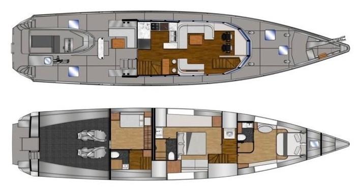
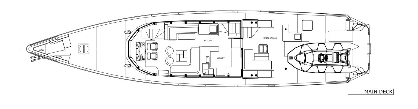
8.2 Parts of Your Vessel
Feature Equipm ent
Hull Overvie w
Waterti ght
Bulkhea ds
Bow Thruste r
Description
General description of the hull structure, material.
Divisions within the hull that are watertight to prevent flooding.
Small propeller located in the bow for lateral movement.
Engines Main propulsion engines (diesel-powered).
Fuel Tanks Stores fuel for the engines.
Freshw ater Tanks
Tanks for storing potable water.
Blackwa ter System Waste management system (holding tanks for sewage).
Anchor and Windlas s Primary anchor with electric windlass for raising and lowering the anchor.
Mooring Lines and Cleats
Ropes and fixed points for securing the yacht to the dock.
Bilge Pumps Automatic and manual bilge pumps for dewatering bilges.
Steerin g Gear Main steering mechanism, including rudder controls.
Trim Tabs
Life Rafts
Hydraulic or electric tabs for adjusting the boat’s trim.
Inflatable life rafts for emergency evacuation.
Fire Extingui shers Fire suppression devices, either dry powder, foam, or CO2 extinguishers.
Fire Blanket Fire blanket stored in high-risk areas like the galley.
VHF Radio with DSC Communication device with Digital Selective Calling (DSC) for emergency and routine communication.
Chart Plotter Electronic navigation system displaying charts and GPS position.
Radar System Detects other vessels and landmasses, useful in low visibility conditions.
Autopilo t Automated steering system that maintains a set course.
Depth Sounder Instrument that measures the water depth below the keel.
Fenders Inflatable or foam-filled cushions used to protect
Location Application
Entire vessel Provides stability, strength, and seaworthiness. Familiarize crew with hull layout and access points.
Throughout hull
Enhance safety by compartmentalizing the yacht in case of water ingress.
Bow Used for maneuvering in tight spaces, especially during docking.
Engine room Power the yacht for forward and reverse motion; familiarize with start/stop procedures and maintenance.
Engine room or below deck
Provides fuel for propulsion; ensure crew knows how to check levels and refuel procedures.
Below deck Supplies fresh water for onboard use (showers, galley, etc.); familiarize with refilling and monitoring.
Below deck Collects and holds sewage; familiarize crew with pump-out procedures and system monitoring.
Bow Used for mooring at anchor; crew must know windlass operation and anchor handling.
Bow, stern, midship
Essential for securing the vessel when docked; crew should know line handling and securing techniques.
Engine room, below deck Used to pump out excess water; familiarize with operation and manual override.
Helm station Controls the direction of the yacht; crew must be aware of emergency steering procedures.
Transom (stern)
Help balance the yacht, especially at higher speeds; familiarize crew with controls.
Deck (usually near stern) Used for emergency evacuation; crew must know the release mechanism and launching procedure.
Galley, engine room, cabins
Used to extinguish onboard fires; familiarize with locations and operation.
Galley Used to smother small fires, especially in the galley.
Helm station, navigation area Used for ship-to-ship and ship-to-shore communication; ensure familiarity with emergency call procedures.
Helm station Used for navigation and course plotting; crew should know basic operation and input of waypoints.
Helm station Essential for navigation in fog or at night; familiarize with radar use and interpreting signals.
Helm station Reduces helm time during long voyages; crew should know how to activate, adjust, and deactivate.
Helm station Helps avoid grounding; crew must know how to read depth and set shallow water alarms.
Bow, stern, midship
Prevents hull damage; familiarize crew with proper placement during docking.
the yacht when docking.
Generat ors Provides electrical power when the yacht is not connected to shore power.
Shore Power Connect ion
Air Conditio ning Units
Safety Equipm ent Storage
Emerge ncy Exits
Electrical connection for plugging the yacht into dockside power.
System for controlling the temperature inside the yacht.
Location of lifejackets, flares, grab bags, and other safety gear.
Alternative routes to exit the yacht in case of emergency (hatches, doors).
Engine room Used to power onboard systems; crew should know start/stop procedures and monitoring of load.
Stern or side deck Provides external power; familiarize crew with connecting and disconnecting safely.
Engine room, cabins
Provides heating and cooling; crew should know how to operate the thermostat and maintain the system.
Deck lockers, interior storage Crew must know where to locate and how to use safety equipment in case of emergency.
Cabins, main deck Familiarize crew with all possible exit points in case of fire or flooding.
8.3 Navigation Equipment
Item Description
GPS Plotter
Electronic chart plotter displaying the yacht’s current position and planned routes.
Radar Radar system for detecting other vessels, landmasses, and weather formations.
AIS (Automatic Identification System)
Displays nearby vessels with AIS transponders, useful for collision avoidance.
Compass Satellite or Fluxgate compass for navigation.
Depth Sounder
Device for measuring the water depth under the hull, crucial for avoiding grounding.
Speed Log Instrument that measures the speed of the yacht through water.
Electronic Charts
Paper Charts
Up-to-date digital navigation charts loaded on the chart plotter.
Hard-copy charts for the area of operation, required as a backup.
Binoculars Marine-grade binoculars for visual navigation and spotting hazards or landmarks.
Autopilot Automated steering system to maintain a set course.
VHF Radio
Navtex Receiver
Marine VHF radio with Digital Selective Calling (DSC) for communication with other vessels and coastal stations.
Receives weather forecasts, navigational warnings, and maritime safety information.
Barometer Measures atmospheric pressure to help predict weather changes.
Clock and Logbook
Echo Sounder/ Fish Finder
Parallel Rulers and Dividers
Signal Flags
Marine clock and logbook to record navigation details, weather conditions, and vessel status.
Device for checking the water depth and detecting objects beneath the yacht, such as shoals.
Navigation tools for plotting courses on paper charts.
International code flags for communication, e.g.,
distress signals or indicating intentions to other vessels. Night Vision Equipment Night vision binoculars or thermal cameras for navigation in low light or night conditions.
www.Exploreryacht.com for the journey. Page 29 of 34
8.4 Anchoring and Mooring
Item Description
Primary Anchor
Main anchor (e.g., plough or Delta), appropriate size for yacht and region.
Anchor Chain Chain (typically 10mm or larger), of sufficient length (e.g., at least 80m).
Anchor Windlass
Kedge Anchor
Anchor Rode
Shorelines (Bow, Stern)
Mooring Lines (General Use)
Fender Lines
Heavy Weather Mooring Lines
Mooring Cleats
Fairleads and Chocks
Mooring Snubbers
Fenders (General Use)
Fender Boards (Heavy Weather)
Anchor Bridle/Snu bber
Mooring Springs
Chain Hook and
Electric or hydraulic windlass, with controls both on deck and at helm.
Secondary, smaller anchor for emergency or stern use.
Length of rope or chain attached to the anchor, minimum 100m for kedge anchor.
Long lines (min 100m) used for mooring to shore in narrow anchorages.
High-quality, nylon or polyester braided dock lines (min 6x, 1620mm thickness).
Strong, shorter lines for securing fenders (minimum 10).
Additional thicker, longer lines (min 20mm) for stormy conditions.
Heavy-duty cleats on the foredeck, aft deck, and midship for securing mooring lines.
Smooth, strong chocks for running lines to avoid chafing.
Elastic snubbers to absorb shock loads on mooring lines.
Cylindrical or spherical fenders, large enough to protect hull during mooring.
Long boards used with fenders to distribute pressure against the hull in heavy weather.
Bridle or snubber line to reduce strain on the windlass while anchored.
Metal or synthetic springs to reduce tension on lines in tidal moorings.
Used to attach mooring lines or bridles to the anchor chain,
Condition Check
Inspect for wear and corrosion. Verify secure attachment to chain.
Inspect for rust, cracks, or kinks. Ensure markings for length are visible.
Test operation regularly, check for oil leaks and mechanical wear.
Check for wear and ensure easy deployment and retrieval.
Inspect for fraying or wear on rope; check chain for rust.
Inspect for UV damage, wear, and cleanliness.
Check for fraying, wear, and stretch. Ensure ends are properly spliced.
Inspect for wear, chafe, and ensure easy handling.
Check for wear, keep stored properly to avoid exposure to elements.
Inspect for corrosion or looseness in deck fittings.
Ensure no sharp edges or corrosion; lubricate moving parts.
Inspect rubber for wear and ensure correct attachment.
Check for punctures, deflation, and UV damage.
Inspect for cracks, rot, and overall integrity.
Check for wear or chafe, especially at attachment points.
Check for rust or corrosion on metal springs.
Inspect for rust and wear; ensure the hook fits the
Grab Hook reducing strain. chain size.
Chain Stopper Device for holding the anchor chain to relieve tension on the windlass.
Bow Roller Strong roller for deploying/retrieving anchor, ensuring smooth chain movement.
Chafe Protection
Mooring Winch
Chafe guards or tubing to protect mooring lines from wear at chocks or cleats.
Mechanical or hydraulic winches for handling heavy mooring lines.
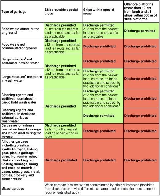
8.5 Waste Management Plan
Check for wear, corrosion, and proper fit to the chain.
Check for smooth operation, no dents or wear on roller surface.
Inspect for wear, ensure proper positioning on lines.
Regularly check operation, lubricate, and inspect for mechanical wear.
Ocean going vessels of 40 feet or longer with a galley and berth must have a written Waste Management Plan.
All persons boarding this vessel, VANGUARD, be aware that under NO circumstances will any garbage, plastic material, food, aluminum cans, bottles, sewage and hazardous substances, etc. be randomly thrown overboard. You must also advise the Captain in case of any oily discharges or diesel spills that you might observe.
There is a trash receptacle located: GALLEY.
Cans and bottles are recycled and have a special receptacle located: GALLEY.
When a trash receptacle is full, the crewmember appointed by the Captain will bag and secure all material until it can be removed from the boat and placed in an appropriate receptacle on shore.
UNDER NO CONDITION WILL ANY TRASH BE THROWN OVERBOARD FROM THIS VESSEL, A simplified overview of the discharge provisions of the revised MARPOL Annex V which will enter into force on 1 January 2013 has been developed by the IMO and is presented here below.
www.Exploreryacht.com for the journey.
Questions concerning this policy, please see the captain of this vessel.
C Leigh-Jones for and on behalf of Vanguard XPM LLC
Owner/Captain
THIS IS ALSO A ZERO TOLERANCE, DRUG FREE, VESSEL.
Ref for Waste Management Plan, US CG Auxiliary. www.
8.6 SYMBOLS AND WARNINGS

General warning sign. To indicate a risk of personal injury.
Read owner's/operator’s manual.
To direct reference to an owner/operator handbook for additional information.
Danger of fires. To indicate the risk of fires.
High voltage warning symbol. To indicate the risk of electrical shocks.
Hot surface warning symbol. To indicate a risk of personal injury by hot surfaces.
Escape direction / escape way


Designated place of the first-aid kit or locker where it is stowed
Designated place of portable fire extinguisher (Inc Fire Blanket) or locker where it is stowed
ISO Class A: Fires involving solid materials, usually of an organic nature, in which combustion normally takes place with the formation of glowing embers.
ISO Class B: Fire involving liquids or liquefiable solids.
ISO Class C: Fires involving gases.
No naked flames; Fire, open ignition source and smoking prohibited. To indicate a possible failure or malfunction.
A red colour indicator with a basic symbol may be used alternatively to indicate a malfunction Muster Station Fixed fire extinguisher location.

9 DISCLAIMER
The description and specifications contained herein were in effect at the time this manual was approved for printing. Even though care has been taken in the preparation of the contents of this Training Manual, VANGUARD XPM LLC does not assume legal or other liability for any inaccuracy, mistake, misstatement or any other error of whatsoever nature contained herein. VANGUARD XPM LLC formally disclaims liability in respect of such aforesaid matters. The information contained within this owner’s manual of a condensed and general information nature only and your boat can change from the contents.