EXCAVATION EXHIBITION
EDUCATIONAL EXCAVATION EXHIBIT CENTRE
CAMBRIDGE, ENGLAND, U.K.
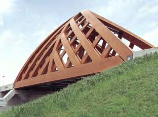
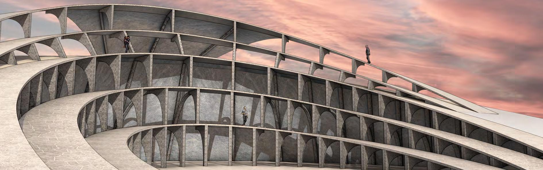
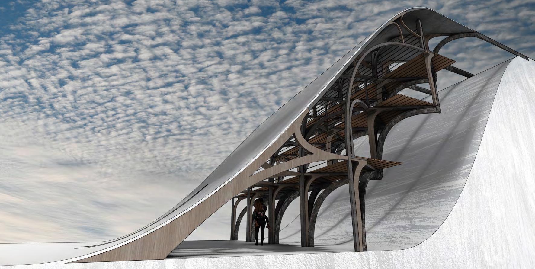
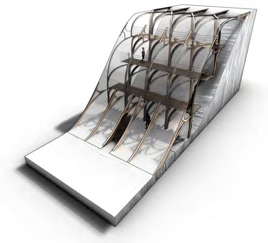
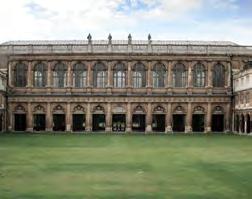
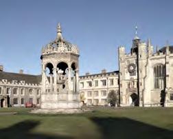
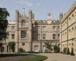
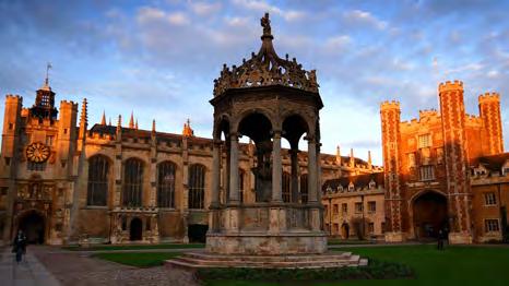
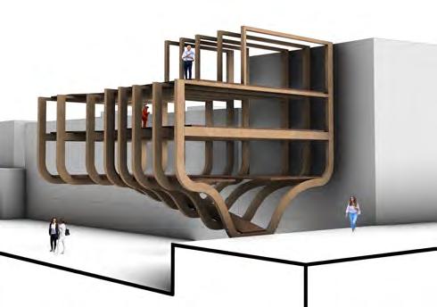
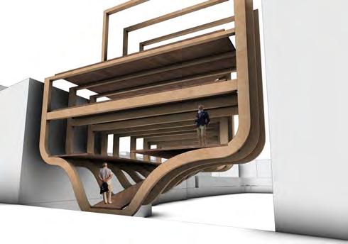
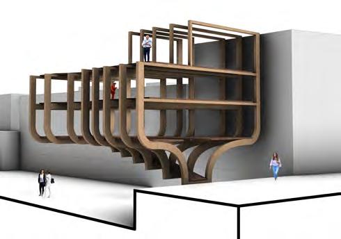
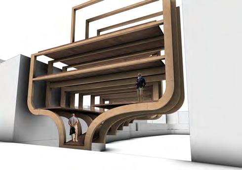
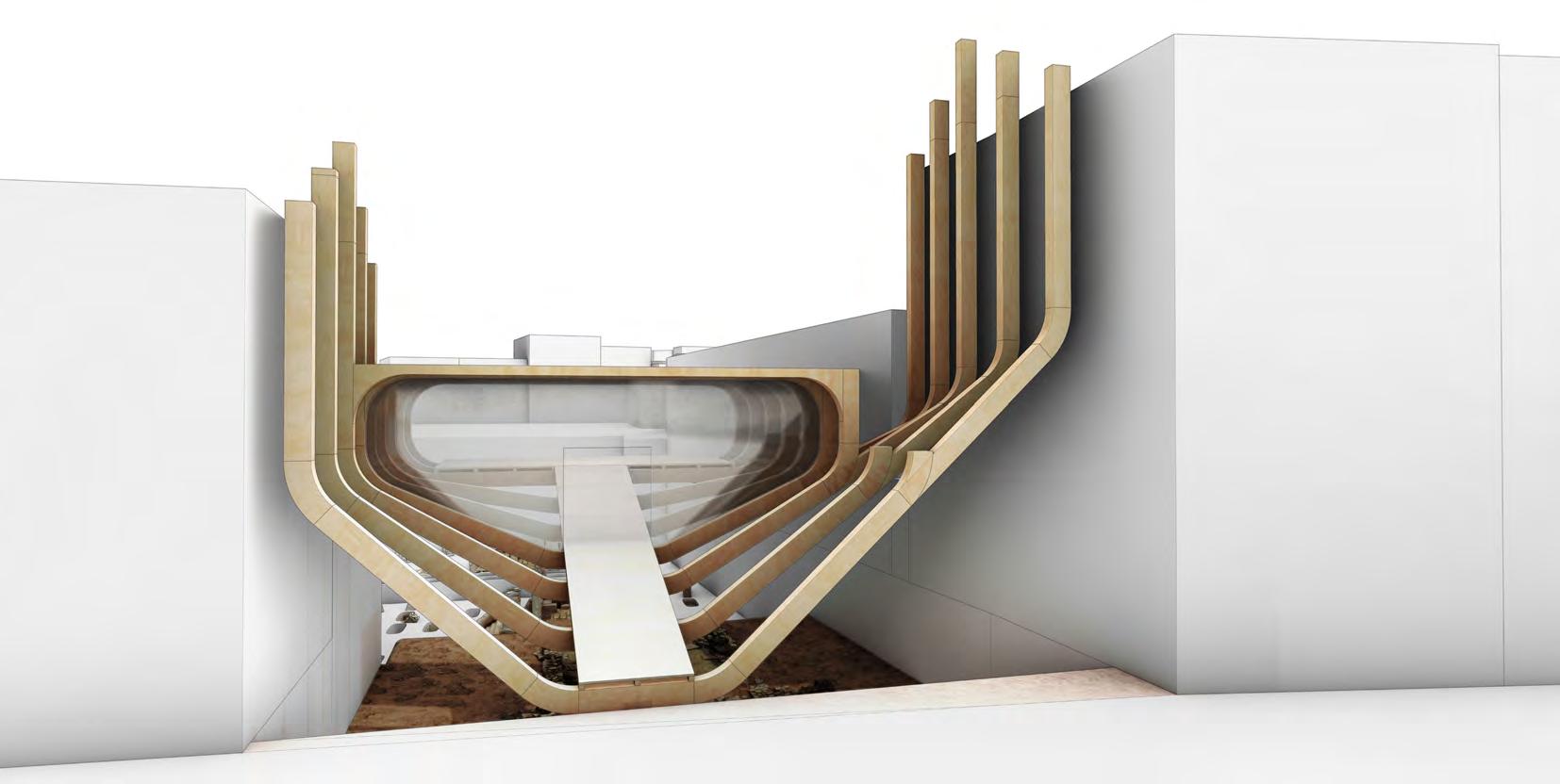
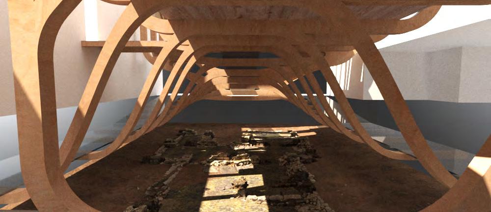
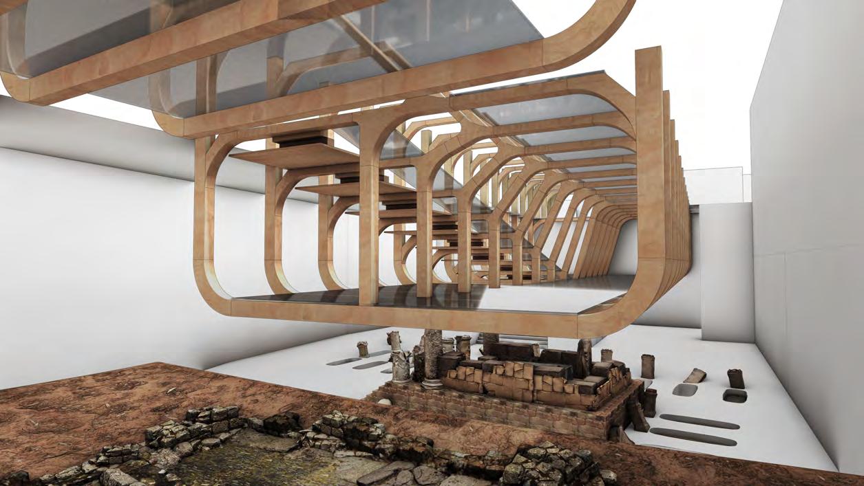
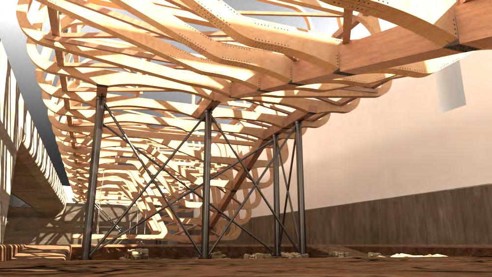
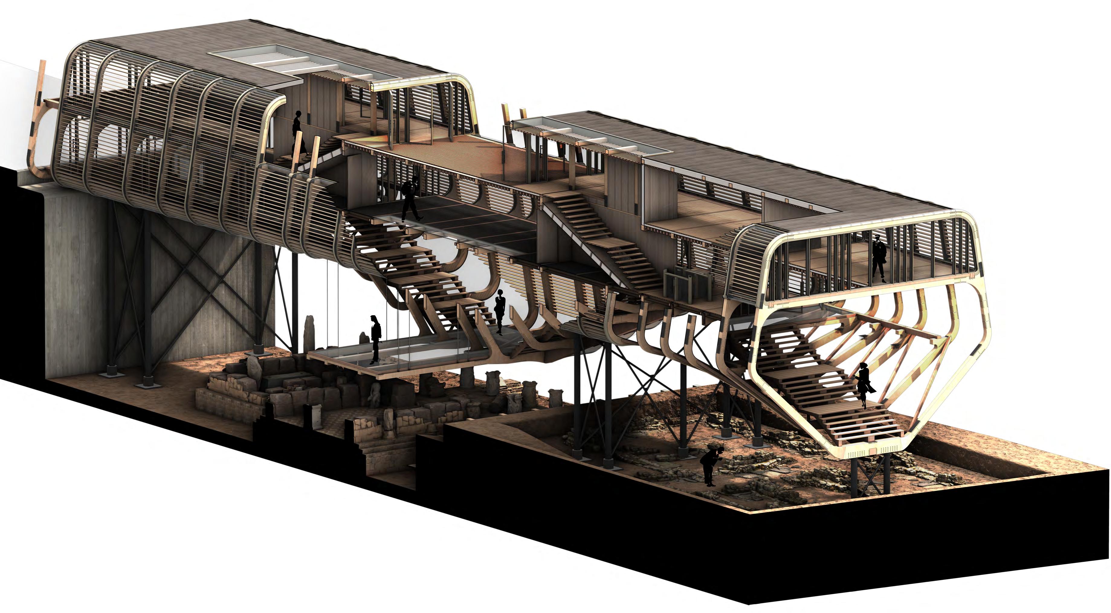
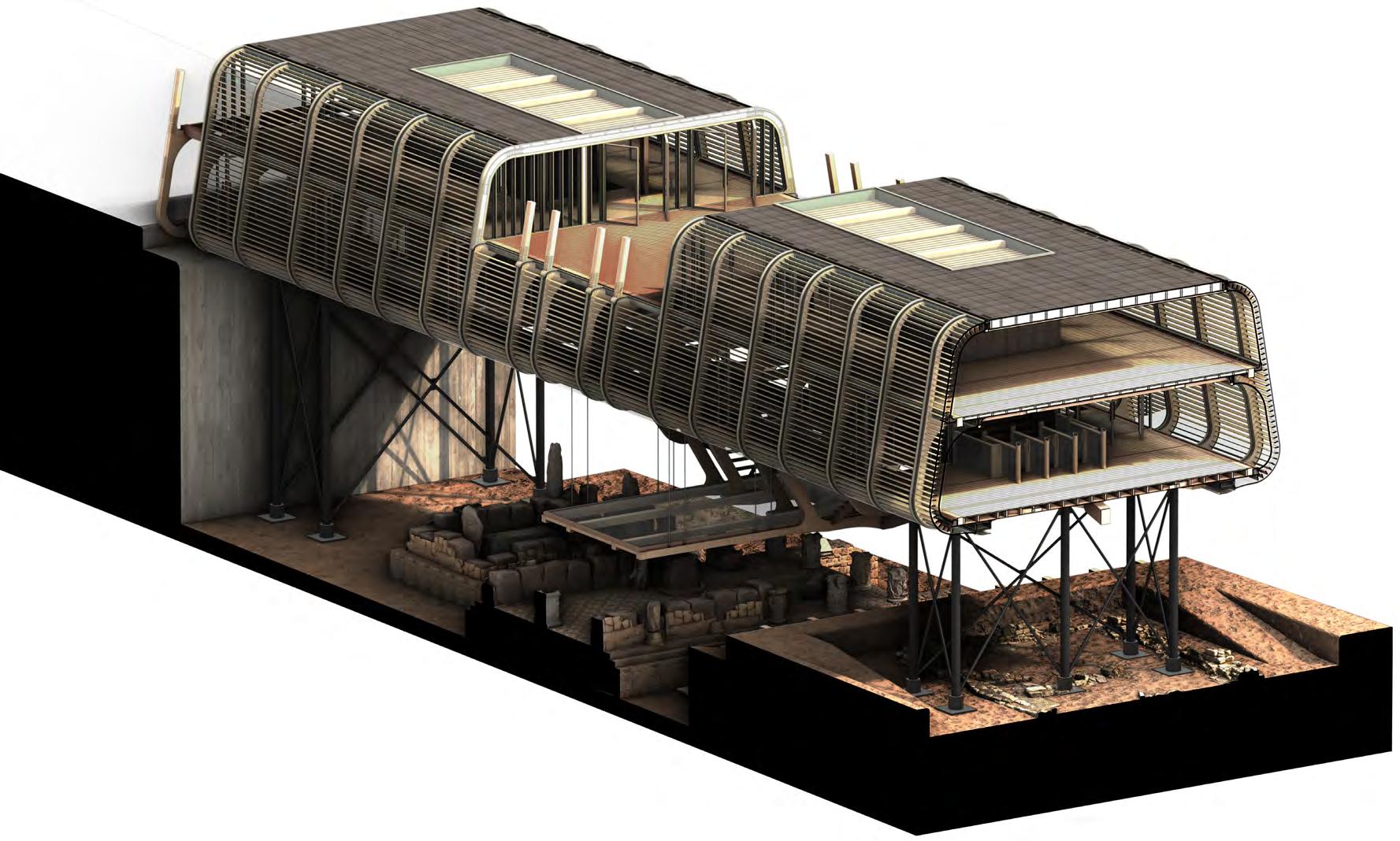
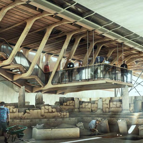
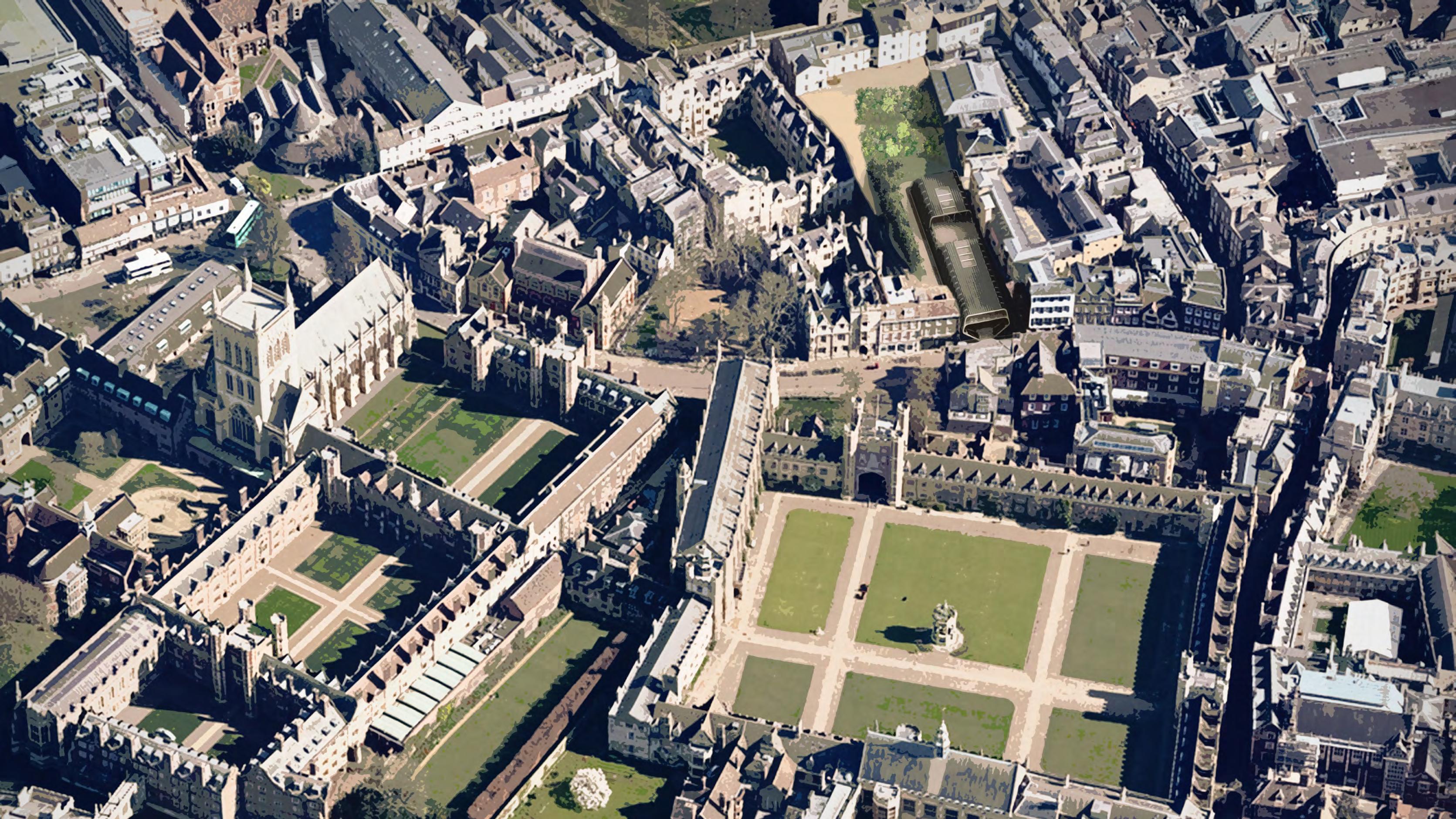
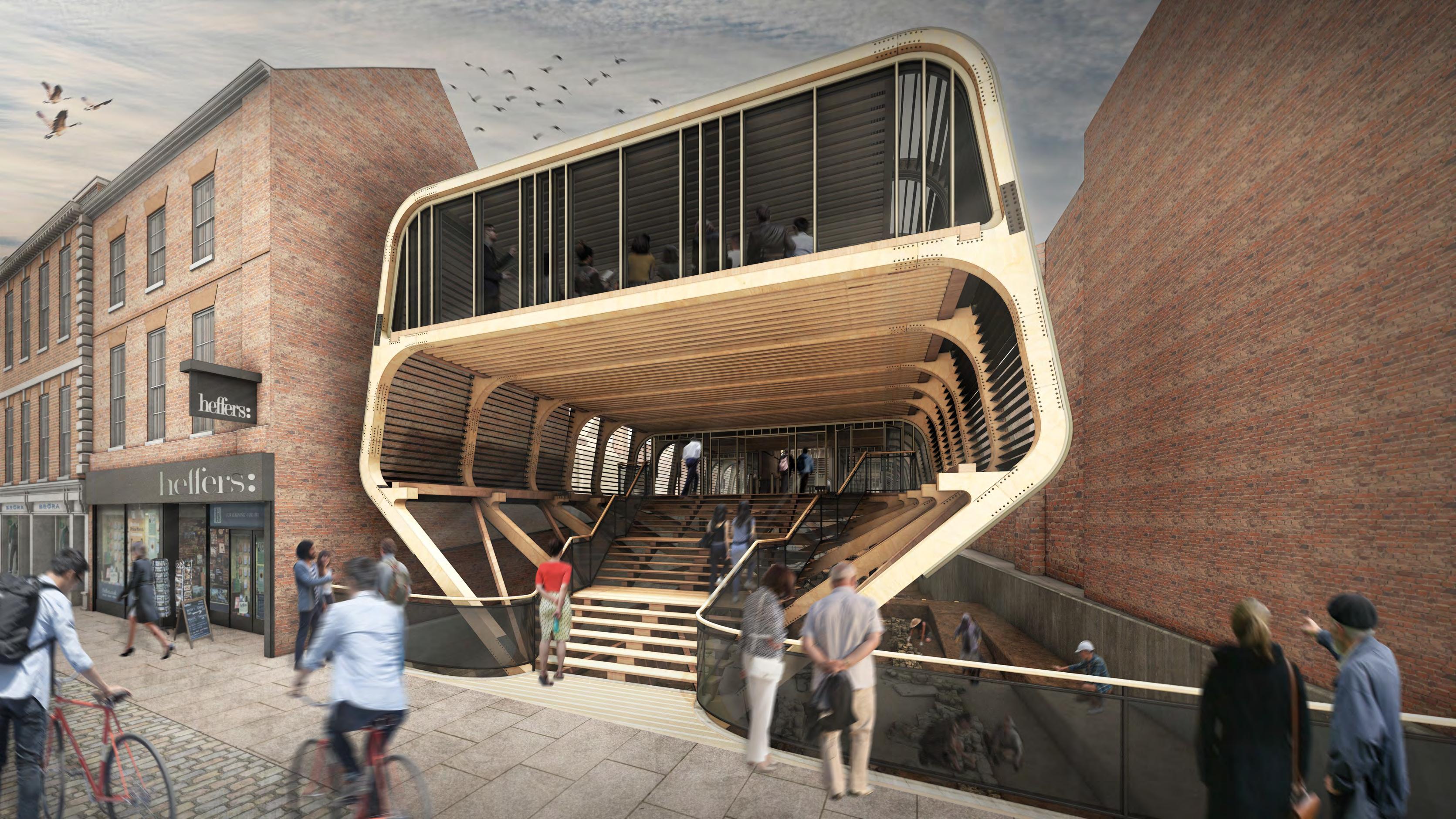
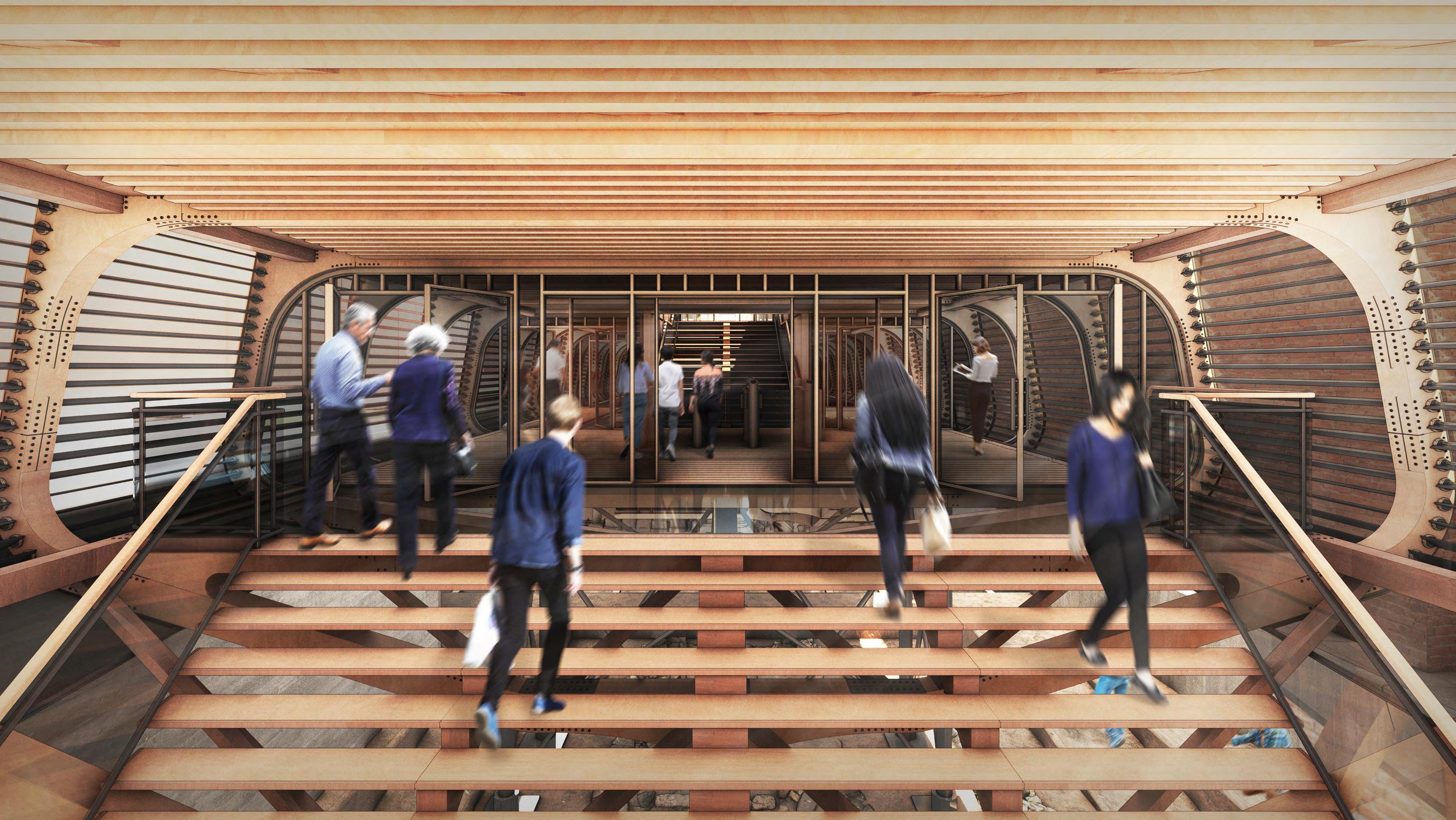
The discovery of ancient ruins unearthed in the urban centre of Cambridge triggers academic and archeological interest in the site, local to Trinity College. In becoming an active dig site for educational excavation and public exhibition, the accoya kit-of-parts building utilises a truss structural system that elevates above the historically sensitive activity; giving a transparency that emphasises its significance.
The design proposal acts to incorporate the public function of an exhibition hall as well as the private functions of educational archaeology teaching and ongoing excavation. This poses challenges from the urban site; being located on a primary street front while dealing with drastically differing levels throughout. The archaeological aspect of the site narrative also presents the constraint of constructing over sensitive historical materials.
In this 25-year project, the newly discovered history of Cambridge is brought to the forefront of the community, allowing visitors to step into the past. At the end of the building’s lifespan, it is intended to be disassembled into its base components, by which it can be transported to the next archaeological dig site; acting in a similar capacity as a semi-mobile dig site office and exhibition centre.
TOM PARRY YEAR 4
Y4 TP
CASE STUDIES + CONCEPT INTERPRETATIONS
ARTEFACT STUDIES
1. Fur protected entryway
2. Level change for wind protection
3. Twig/Moss/Leaf floor covering
4. Animal fur insulation
5. Heated air pocket
6. Accumulating snow
7. Translucent light brick
8. Ventilation hole
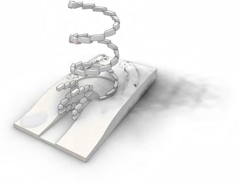
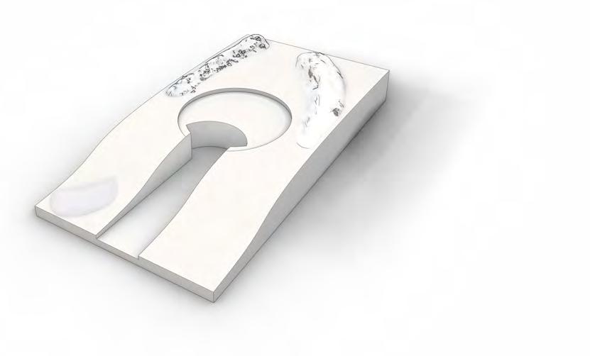
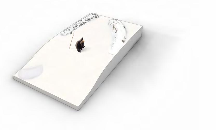
Igloo dESIgn concEpt
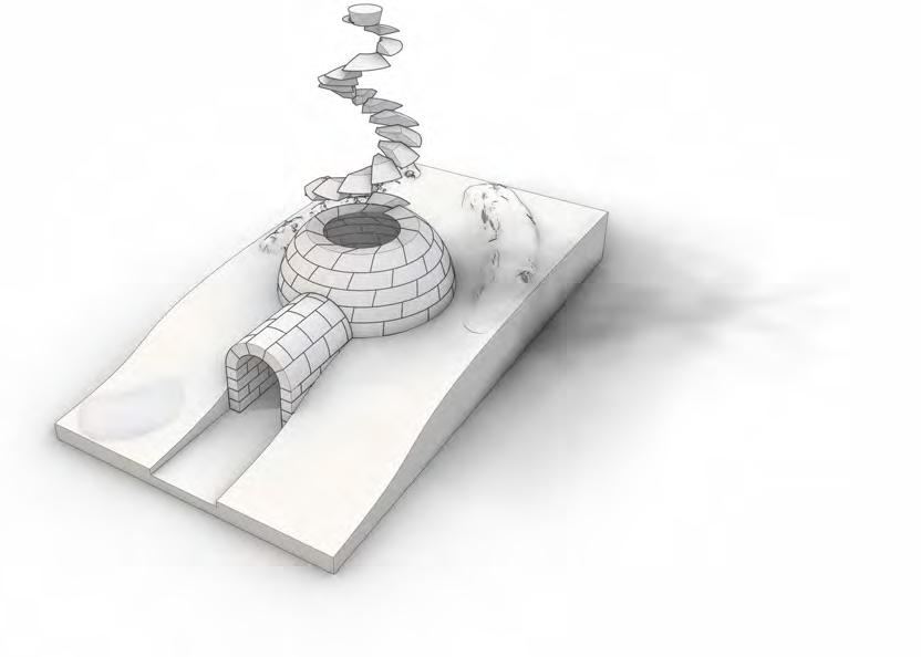
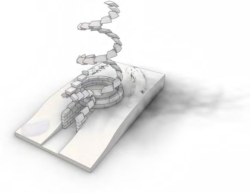
Using only snow cut from the ground, the igloo is built on the same hole to form a shelter merged into the landscape. With a step in the main sphere space and elongated entryway, hot air is trapped within while still ventilated via a small hole cut in the dome.
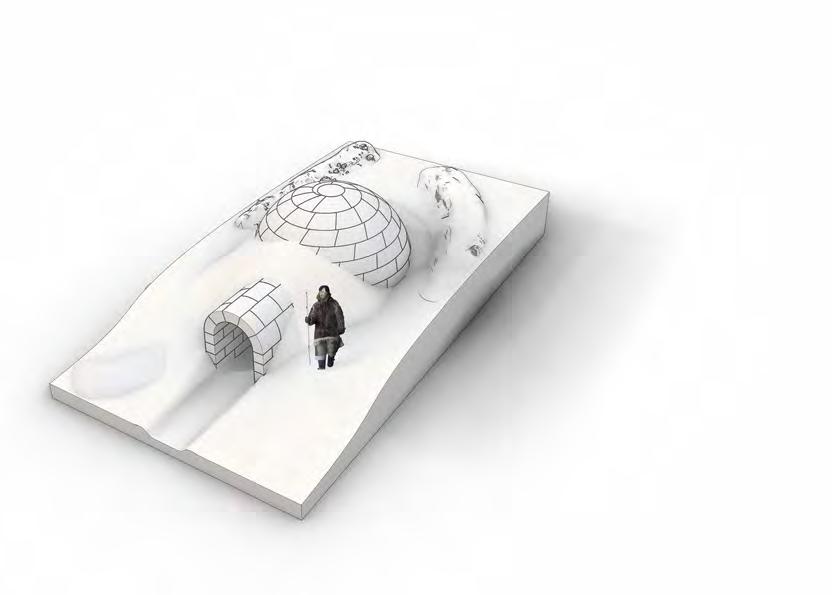
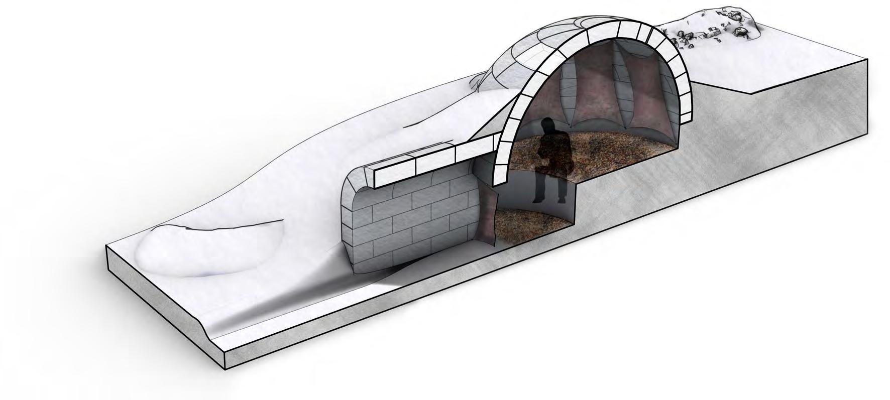
9. Compact shape for wind protection low tEch conStructIon
6.
The igloo is built using simple technology; cutting snow blocks out of the ground and using these to create the shelter. The bricks are angled to make them self supporting during assembly, eliminating the need for scaffolding and or additional fixings.
ExcavatEd SructurE
STUDY ONE: IGLOO
1 2 3 4 5 6 9 9 7 6 8
1. SItE ExamInatIon
2. matEr al ExcavatIon
3. BaSE Br ckS
4. FurthEr Br ck layIng
5. FInIShIng cap
complEtEd Igloo

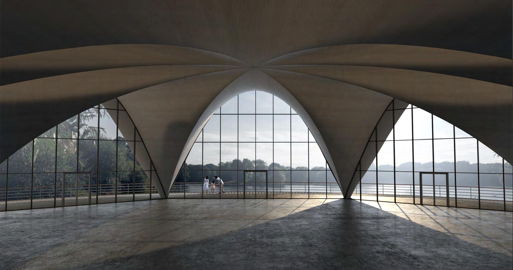
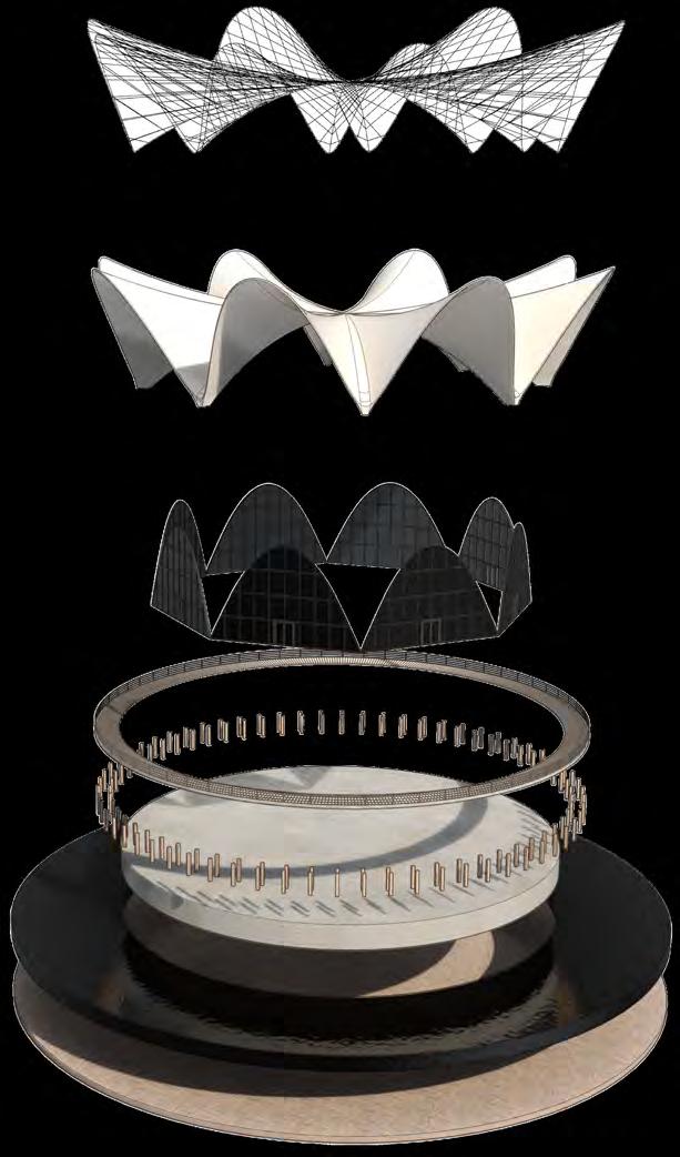
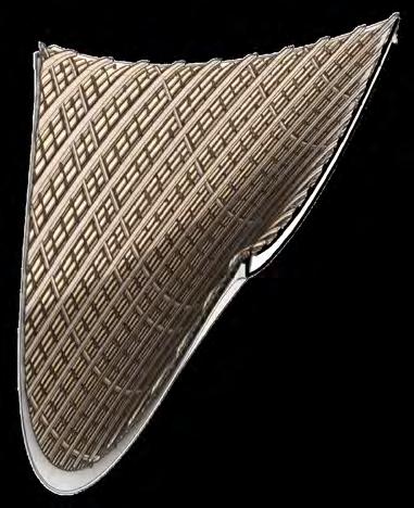
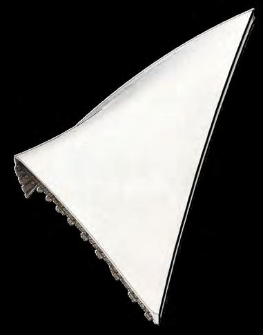
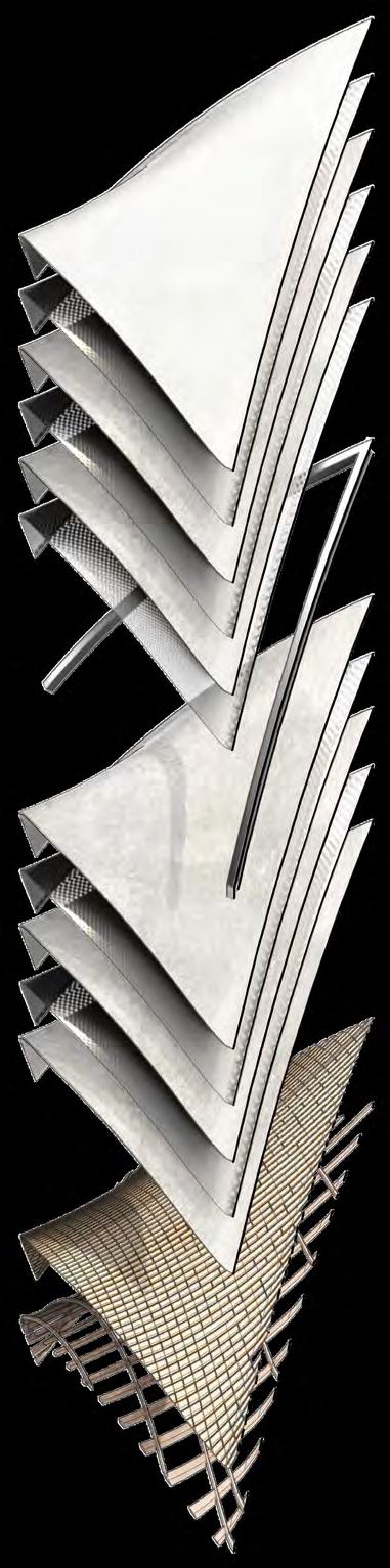
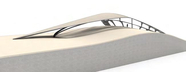
STUDY TWO: LOS MANANTIALES, FELIX CANDELA FErrocEmEnt conStructIon tImBEr Formwork undErSIdE ExplodEd StructurE layErS complEtE hypar FragmEnt matEr al layErIng Cement grout / Concrete Cement grout / Concrete Steel mesh reinforcement Steel mesh reinforcement Finished external concrete Steel reinforced ‘V’ beams Finished internal concrete Timber board formwork Timber support structure
When a fire breaks out in historic Central Cambridge, devistating a the student accommodation and Graded buildings situated there, ancient Roman and Medieval ruins are discovered upon the site’s excavation. Occuring on the University of Camebridge’s (Tinity College) grounds, the site is given over to the archeology department as a temporary (20 years) dig site for research and educational practice.
tEnSIon and comprESSIon SyStEm


Convex and concave hyperboilc curves under compression and tension


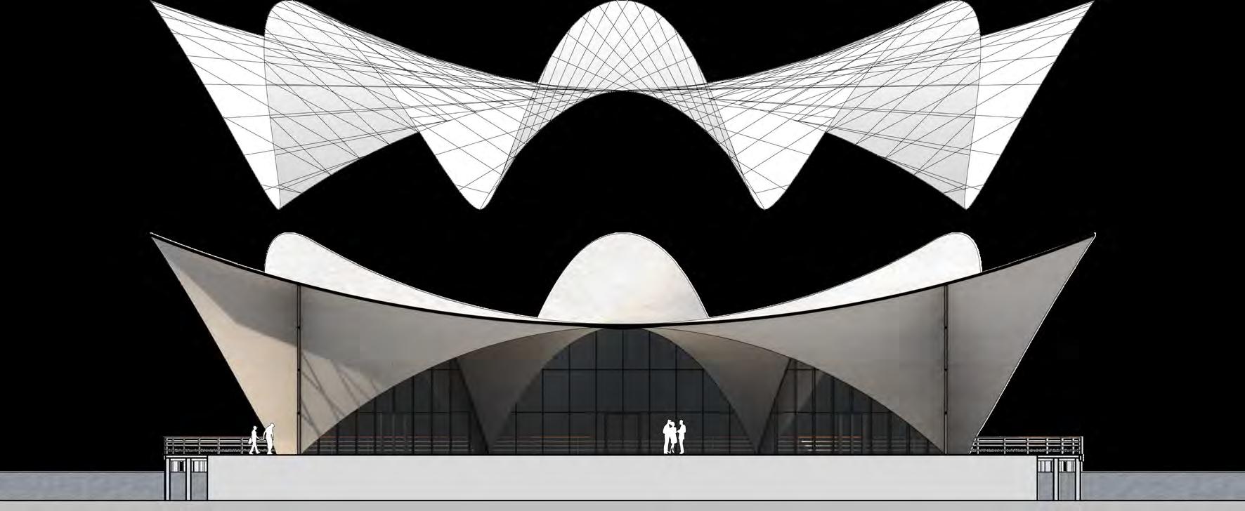

STUDY TWO: LOS MANANTIALES, FELIX CANDELA
hypErBolIc paraBolo dS Parabolic arch Hypar curve Hypar curve Steel groin Parabolic arch
hypErBolIc paraBoloId
pIlE anchor poIntS Single points at which the groins are anchored via pile foundations Structural gro nS
cores running through intervals of the structure to bear major loads
Steel
SEct onal StudIES
tImBrEl tIlE arrangEmEnt load dIStrIButIon
tImBrEl vaultEd cEIlIng


tImBrEl BrIck arrangEmEnt load dIStrIButIon
t mBrEl vaultEd arch


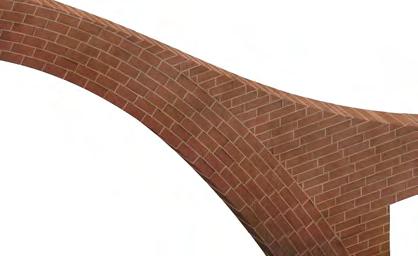
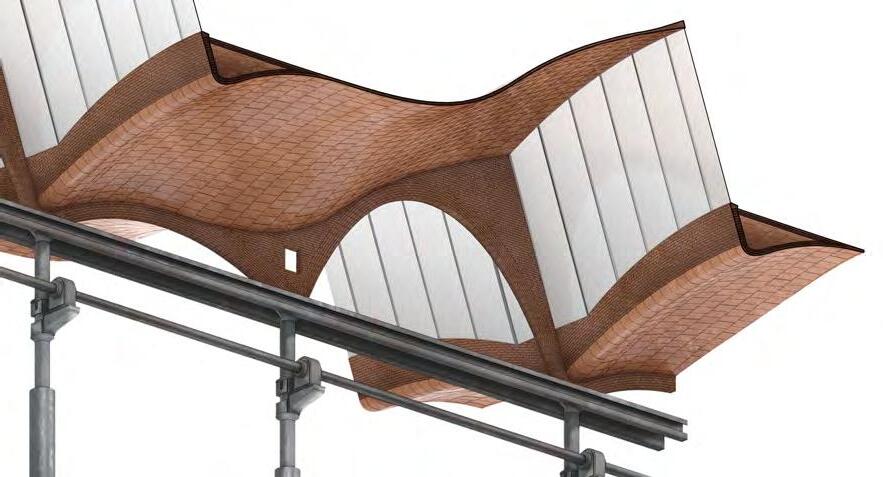
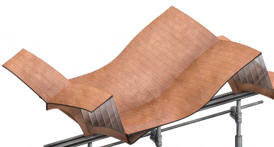
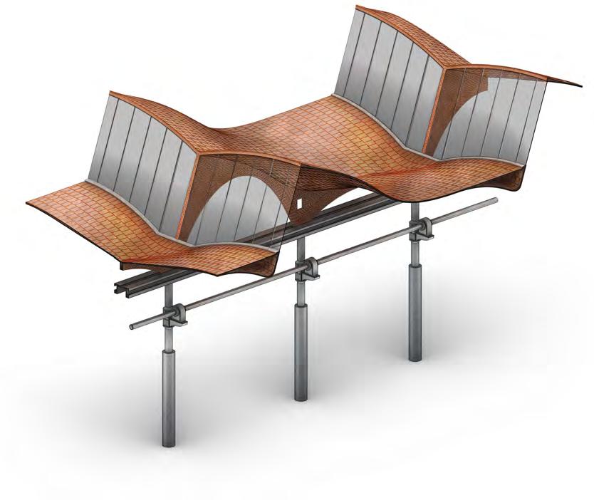
runn ng pattErn tIlE StackIng
Tiles layered in alternating alignments with cement bonding
hErrIngBonE pattErn tIlE StackIng
Tiles layered in alternating alignments with cement bonding
tImBrEl vaultEd cEIlIng + arch
STUDY THREE: THE VAPOR AYMERICH AMAT I JOVER
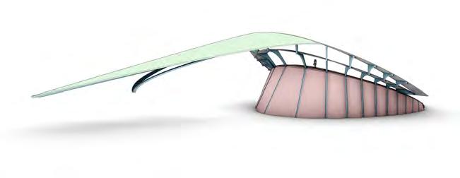


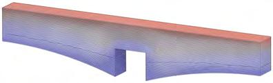
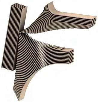
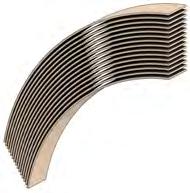
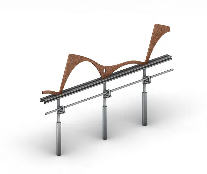
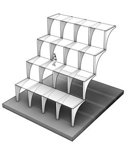
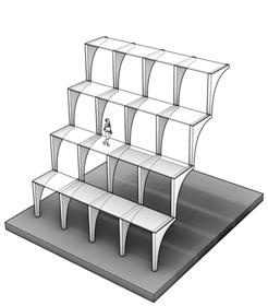
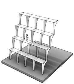
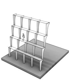
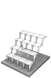
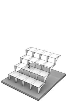
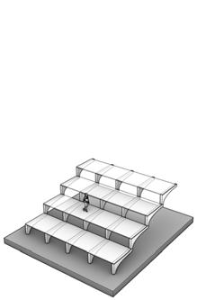
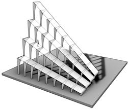
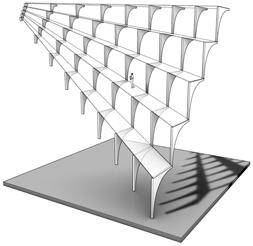
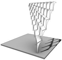
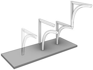
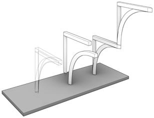
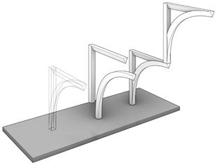
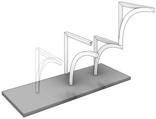
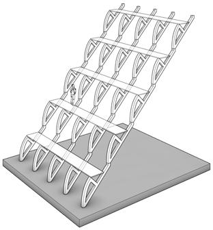
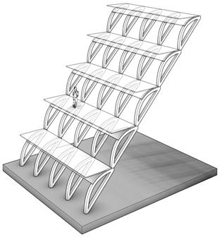
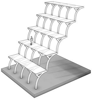
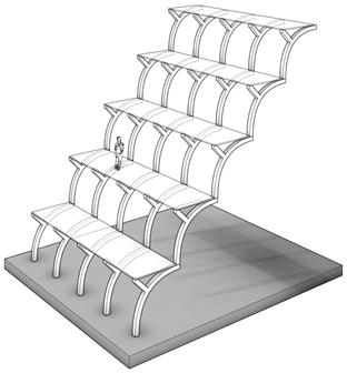
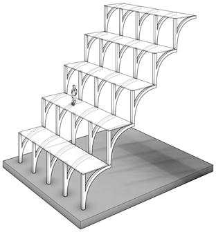
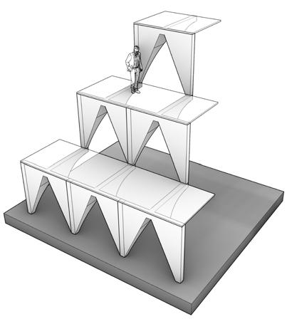
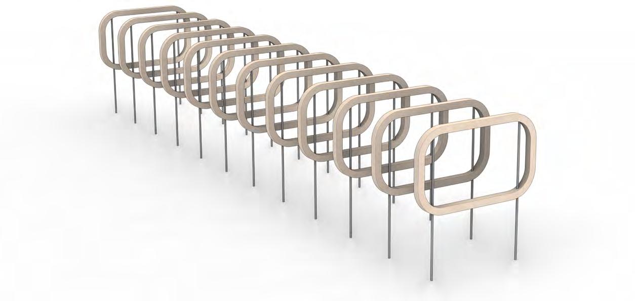
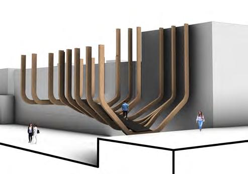
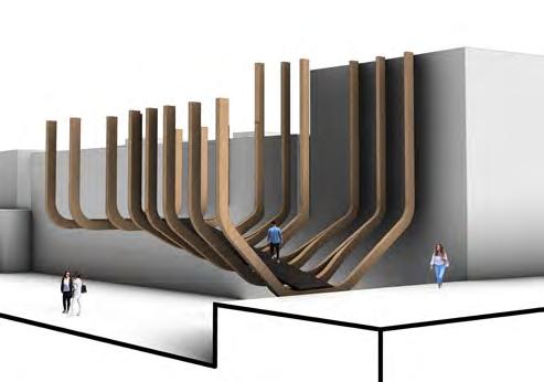
ARTIFACT EXPERIMENT ONE hypErBolIc rIB StackIng StagE 4 StagE 3 StagE 2 StagE 1 StagE 5
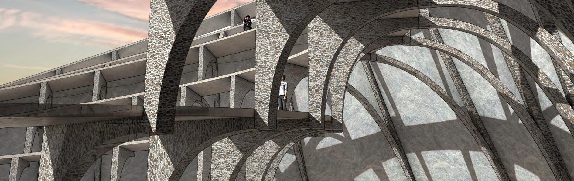
ARTIFACT EXPERIMENT ONE BlEndIng wIth EnIronmEnt

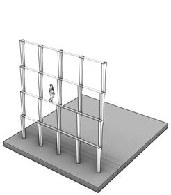


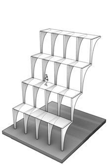
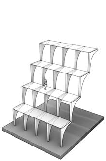
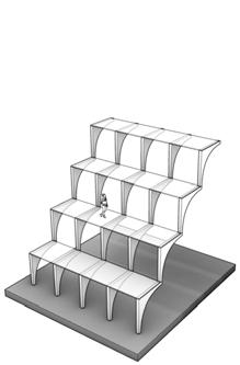


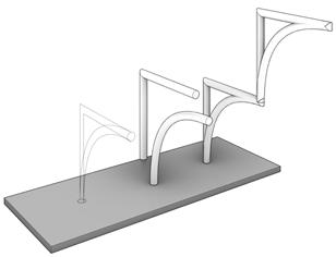
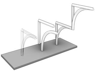
STACKING STUDIES proFIlE SpanS Side profile horIzontal Span vErtIcal Span Side profile hor zontal + vErtIcal SpanS
SIDE PROFILE
SIDE PROFILE
proFIlE Form ExpErImEntS
EXTRUSION PROFILES


EXTRUSION PROFILES ExtruSIon Form ExpErImEntS
rIB Form ExpErImEntS
STUDIES
STACKING


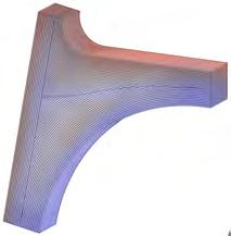
RIB STACKING STUDIES StackEd Form ExpErImEntS PLAN PROFILE FRONT PROFILE ExpanSIvE S nglE to douBlE prongS PLAN PROFILE FRONT PROFILE rEducIng douBlE to SInglE prongS
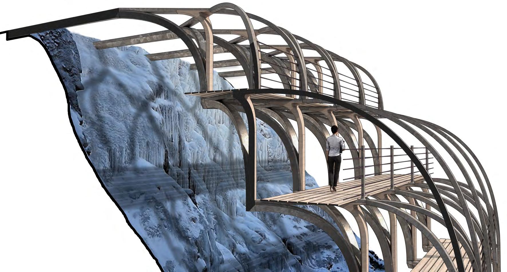
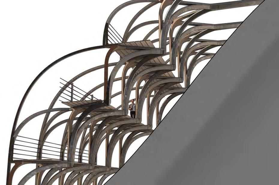
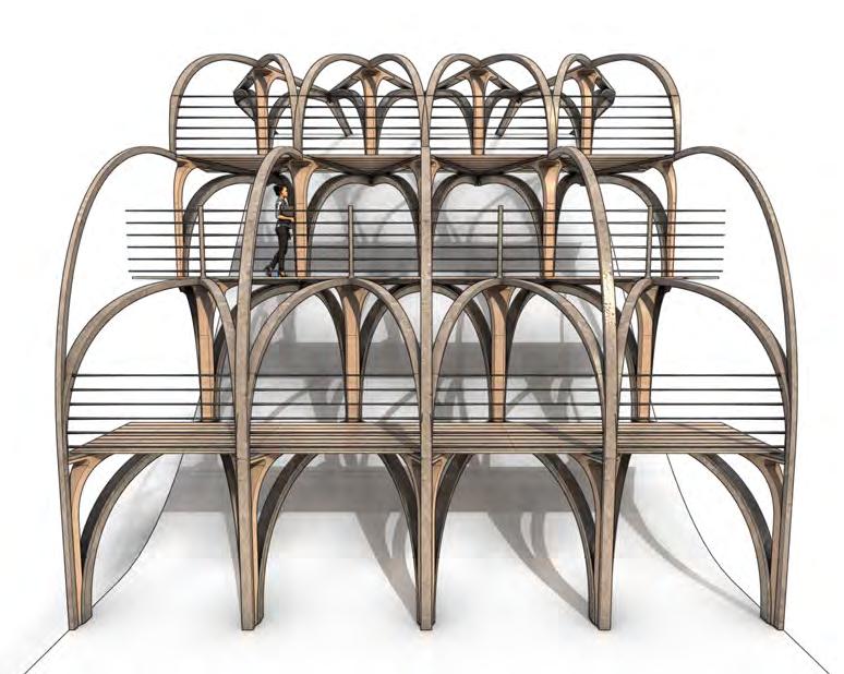


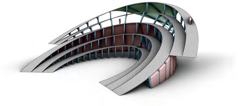
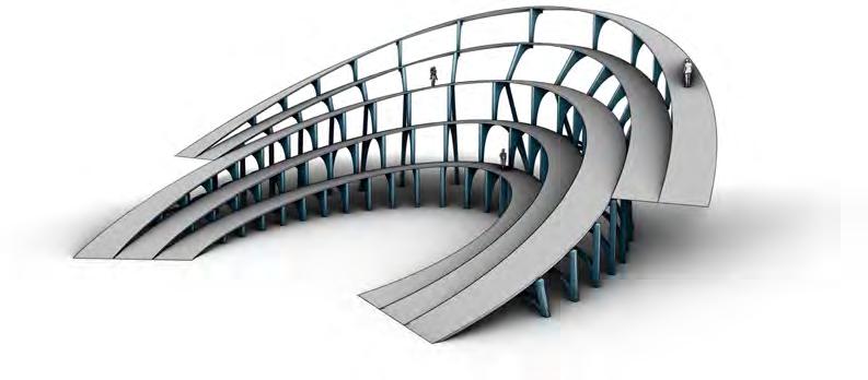
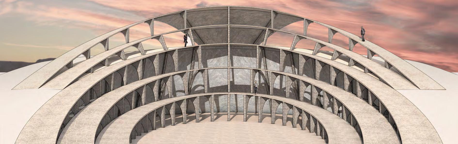
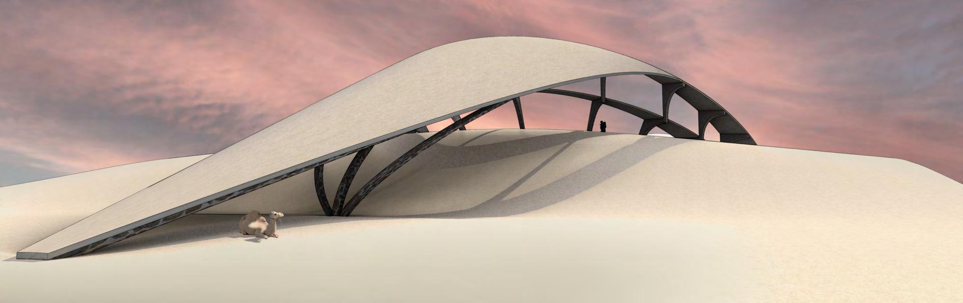
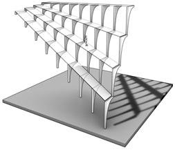
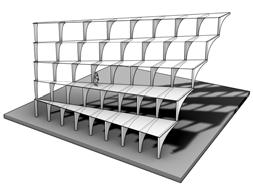
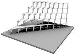
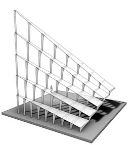
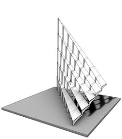
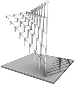
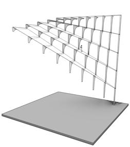
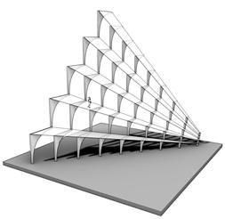
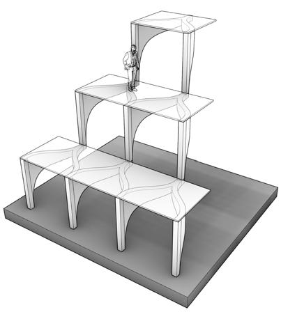
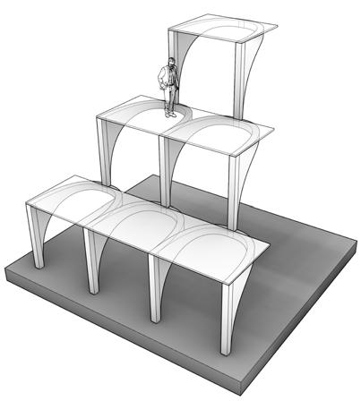
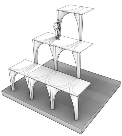
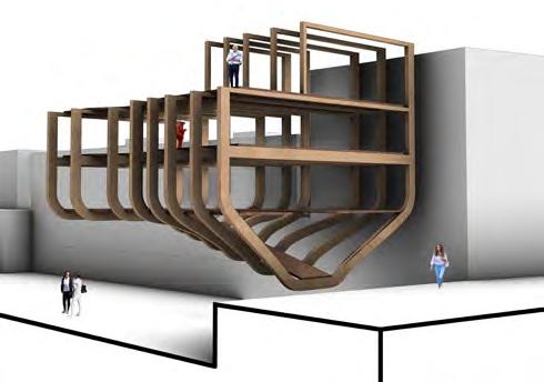
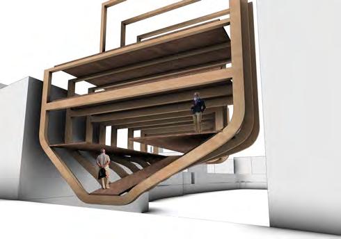
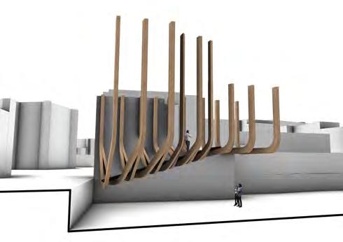
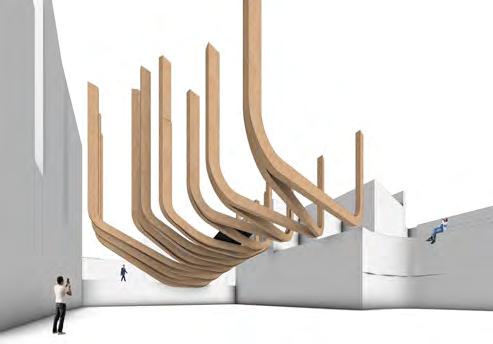
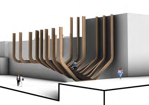
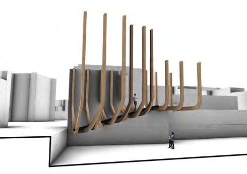
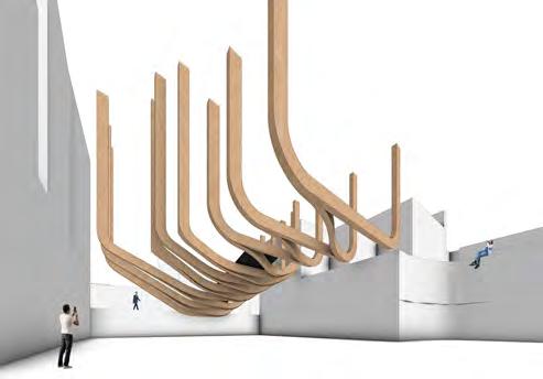
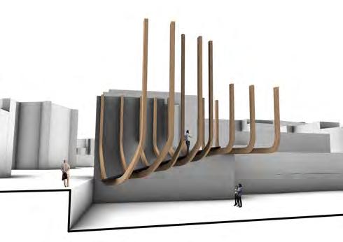
ARTIFACT EXPERIMENT TWO StackEd rIB conStruct BuIldIng onto a landScapE StackIng and latEral ButrESSES rIB componEnt dEvElopmEnt

ARTIFACT EXPERIMENT TWO EncloSIng protEctEd SItE
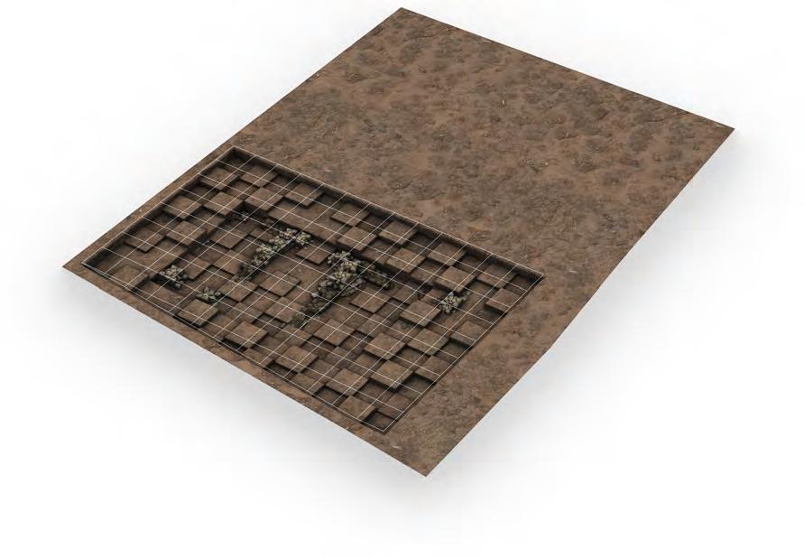
oFFSEttIng landScapE
Creating a false offset landscape that mimics that which is underneath, enabling excavation workd to be carried out without disrupting the natural landscape.
The project uses laminated timber in large spanning beams and columns as the primary structure. Fabricated off-site and assembled in careful coordination, it was built using only simple fixings and mostly by hand. The structural load is supported by thin metal pillars at frequent intervals to avoid intrusive and damaging foundations.
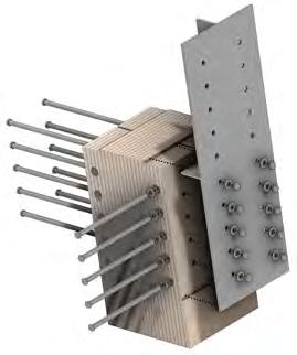
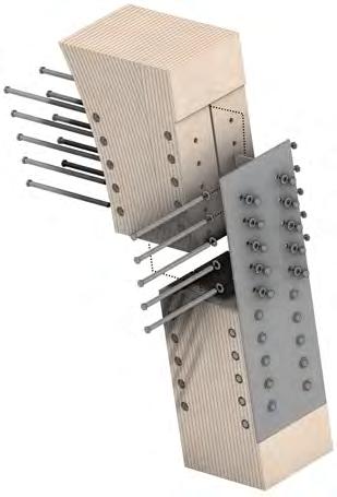
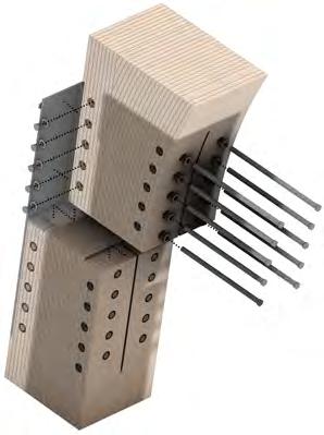
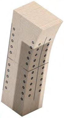
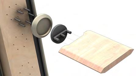
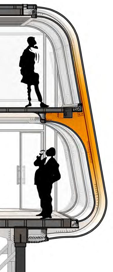
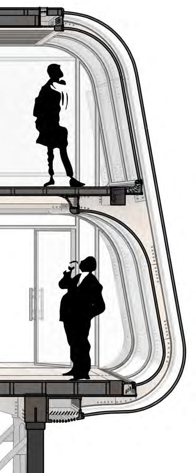
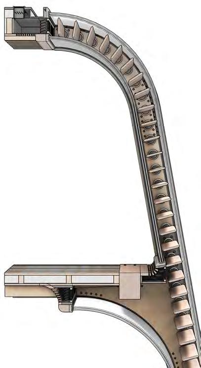
STUDY FOUR: PROMETEO, RENZO PIANO FrEEStandIng StructurE In a StructurE
plan SEctIon column JoInt FIttIngS
Structural JunctIon
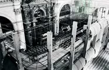
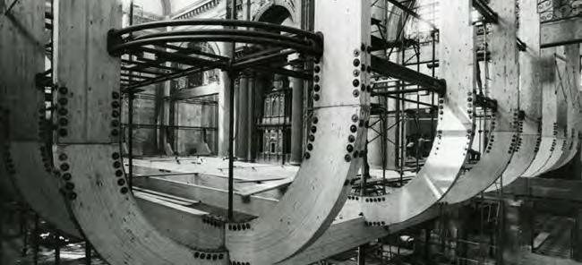
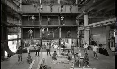

STUDY FOUR: PROMETEO, RENZO PIANO prEFaBrIcatEd kIt oF partS aSSEmBly
SITE, BRIEF + PROGRAMME NARRATIVE
Project narrative
When a fire breaks out in historic Central Cambridge, devistating a the student accommodation and Graded buildings situated there, ancient Roman and Medieval ruins are discovered upon the site’s excavation. Occuring on the University of Camebridge’s (Tinity College) grounds, the site is given over to the archeology department as a temporary (20 years) dig site for research and educational practice.
Construction of the structure progresses in several stages alongside the site’s excavation, acting as a shelter to the archeological work while also housing the artefacts disocvered. As an active street frontage, the excavations and discoveries are displayed to the public in and open exhibition, encouraging educational engagement, generating financial provision and easing planning consent. Meanwhile, archeological work remains visible but private, allowing the site and artefacts to be analysed and catalogued securely.
As the excavation is completed, all known artefacts catalogued and removed, and financial incentive moving elsewhere, the project draws to a close. In awaiting the next proposal for the site, the structure is disassembled for components to be used elsewhere, artefacts are relocated and the ruins are sealed in a protective enclosure, to be encorporated into the next proposal.
1. ancient ruins DiscovereD
Following the destruction caused by the fire at Wolfson Building, ancient Roman and Medieval ruins are discovered during clearing of site.
3. strategic Definition Setting of the project objectives, building requirements and strategic brief, with specific consideration to how the project will approach the archeological constraints.
5. archeological excavation commences
Initial geological scans reveal the extents of the archeological site so digging can begin to unveil the bulk of the ruins, as well as suitable placement for later foundations.
7. DeveloPeD Design Consultants become increasingly involved as a coordinated and more detailed design is developed.
9. site PrePeration comPletes
Initial archeological site surveys and excavations are comlpeted to give an outline understanding of the constraints and sensitivities to be stricktly followed during construction.
11. on site construction commences
Foundations are laid on site and pre-assembled frames delivered so that on site construction can begin in full. Architects and consultants are also on site to resolve design qeries where they may arise.
13. PuBlic exhiBition oPens
Public exhibition and ruin overlook spaces are completed for inhabitation, allowing them to be opened and triggering the start of the primary public financial income for the project.
15. hanDover + close out Construction is finalised and the site cleared, allowing the building to be entirely put in responsibility of the client with the building contract concluded.
4)
17. excavations concluDeD Archeological excavations have uncovered all that is to be uncovered, triggering the start of the building’s end of life, where in artefacts are relocated to storage/museums and the public programme begins to shut down.
19. Kit of Parts relocateD
The building components are transported from site, either to storage or directly to the next archeological dig, where it will be rebuilt again under the same programme.
Project timeline


2. trinity college funDing
The decision is made to fund a new archeology department, using this project as a launch pad to a permenant proposal in the future.
4. PrePeration + Brief
Developing the project brief in greater detail, with regards to project objective and aspirations; quality, cost, timescale and impact objectives; project outcomes, sustainability goals and project budget.
6. concePt Design
The architectural design team prepare concept design, including outline proposals for structure, building services, outline specifications and setimating preliminary costs.
8. technical Design
Following the previously layed out project strategies and objectives and Deign Responsibility Matrix, technical designing begins.
10. Kit of Part ProDuction
Materials sourced from overseas arrive for manufacture into the kit of parts, being assembled into frame modules off site in preparation for transport to site, in accordance with the agreed upon construction programme.
12. PuBlic Digs taKe Place
While construction is ongoing on the building above, excavtion continues below, with the public invited to take part in public digs, bringing initial financial gain to the project.
14. eDucational facilities oPen
Fit out of the educational spaces is completed and operational, allowing intergration into Trinity College teaching. Work continues in completing the remaining archeological park.
16. BuilDing use life
The building enters life in full use, with excavations ongoing in educational practise and public digs; educational facilities fully operational; and intergration strategies into the local and academic communities underway.
18. DisassemBly commences
The building is closed to both the public and university, with the kit of parts dismantled into the original components and frames, leaving only the foundations and immovable ruins.
20. site PreP Begins
The ruins are given temporary protection and the site cleared and prepared for the next, permanent archeology department building to be construction.
NARRATIVE
D esign + c onstruction P re P aration o nsite c onstruction + u se e n D of P roject l ife P roject c ommencemet 2023 (Year 0) 2024 (Year 1) 2025 (Year 2) 2026 (Year 3) 2027 (Year
2048
2047 (Year 24)
(Year 25)
uK archeological sites


NARRATIVE
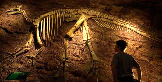
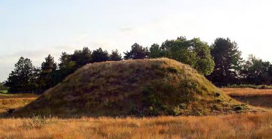
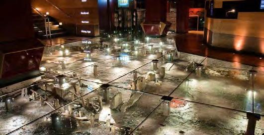
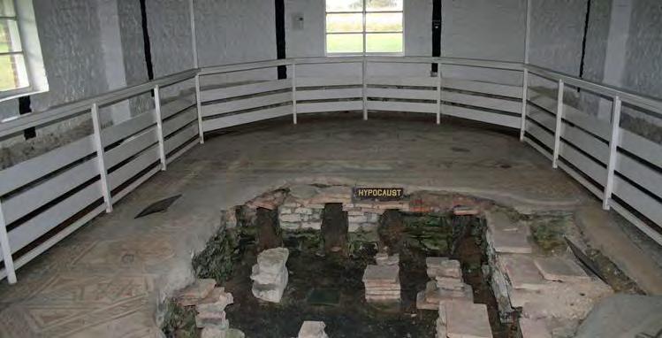
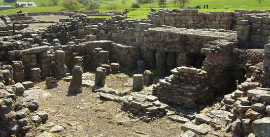
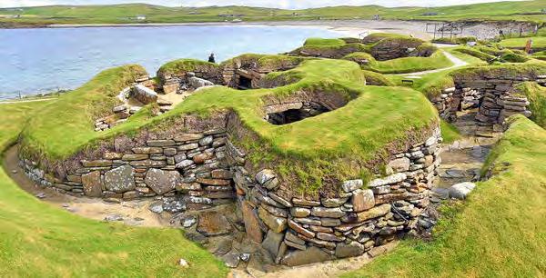
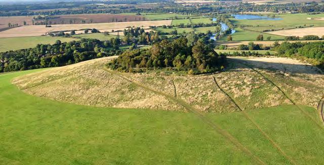
Historic Era: Dig Status: Exposure: Public Interaction: Exhibition: Historic Era: Dig Status: Exposure: Public Interaction: Exhibition: Historic Era: Dig Status: Exposure: Public Interaction: Exhibition: Roman (c.5th - 9th CE) Ongoing External dig w/ internal exhibition Tours amd dig viewing Museum w/ local discoveries Neolithic (c.3000BC) Ongoing since 2004 Fully external Tours and public digs None Roman / Bronze age / Iron age Finished Fully external Visual only None 4. Wittenham clumPs 5. ness of BroDgar / orKney islanDs 6. vinDolanDa / haDrian’s Wall Historic Era: Dig Status: Exposure: Public Interaction: Exhibition: Historic Era: Dig Status: Exposure: Public Interaction: Exhibition: Historic Era: Dig Status: Exposure: Public Interaction: Exhibition: Roman (c.190 - 400AD) Finished Internal and external Educational tours Structure remains, no artefacts Medieval (c.900AD) Finished Fully internal Educational “time warp” experience Local discoveries and recreated village Roman (c.1st CE) Ongoing External dig w/ internal exhibition Educational programmes, tours Local discoveries and restored temple 7. BloomBerg Place 8. jorviK v King centre 9. Bignor roman villa 1. sutton hoo Historic Era: Dig Status: Exposure: Public Interaction: Exhibition: Historic Era: Dig Status: Exposure: Public Interaction: Exhibition: Historic Era: Dig Status: Exposure: Public Interaction: Exhibition: Medieval (c.6th - 7th CE) Finished Fully external Visual only Viewing walkways Jurassic Finished Fully internal Educational programmes Mock dig-sites, local discoveries Prehistoric (c.2000BC) Finished External w/ internal exhibition Tours, annual events, cafe Local discoveries 2. Dinosaur isle 3. stonehenge Cambridgeshire 1 7 2 9 12 8 3 4 6 5
toWn of DuroliPonte founDeD
occuPieD as a miltiatry station
Few stone buildings; predominantly timber
settleD By saxon invaDers
occuPieD unDer Danish rule
church of st Benet constructeD
Oldest surviving building
norman castle Built on castle hill camBriDge recieves its charter
first scholars seeK refuge
“Founding” of University of Cambridge


Peterhouse college founDeD
The first college of Cambridge
recogniseD By PoPe john xxii

trinity college founDeD
Today’s largest and wealthiest college
camBriDge university formeD

Combining Cambridge’s colleges

First newspaper, hospital and bank founded
Connected to London via railway
Wolfson BuilDing constructeD
As student accommodation for Trinity College
aDDition of roBinson college
The final to join the University; totaling 31
fire outBreaK at Wolfson BuilDing
Destroying it and 19-20 Trinity Street
Cambridge Cambridgeshire
camBriDge archeology

Huntingdon archeological sites


Cambridge
Town Centre General Monastic House
heaDlines
Central Cambridge

NARRATIVE
43 AD Roman 70 AD 410 AD Saxon 875 AD Danish 1025 AD 1068 AD Medieval 1207 AD 1209 AD 1284 AD 1546 AD Tudor 1571 AD 17441780 AD Georgian 1845 AD Victorian 1972 AD Modern 1977 AD 2023 AD Contemporary 1318 AD
timeline of camBriDge
Founded


NARRATIVE trinity college - university of camBriDge Location: Motto: Founded: Financial Endowment: Founded: Undergraduates: Postgraduates: Trinity Street, Cambridge 1546 (477 years ago) £1.87bn 1546 (477 years ago) 730 350 VirtusVeraNobilitas “Virtue is true nobility” trinity college university of camBriDge
Henry VIII
1546,
College
century
the University of Cambridge
in
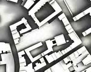
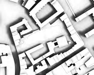
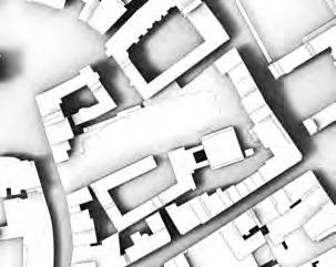
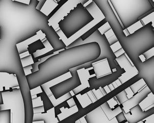
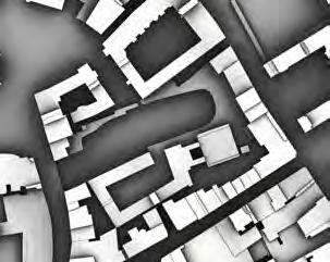
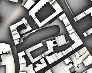
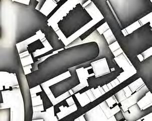
to academic achievement. Regent House senate Board of Scrutiny university of camBriDge council Education Planning + Resources Buildings Research Policy Finance Committe Council of SChools general BoarD trinity college camPus construction PerioD Map Product: UKBuildings (Age) Basemap: UKBuildings (Age) Mixed Age Part Postwar Mixed Age Part Interwar Mixed Age Part Historic Historic Temporary Building Non-Building Structure Unclassified Map Product: UKBuildings (Age) Basemap: UKBuildings (Age) Mixed Age Part Postwar Mixed Age Part Interwar Mixed Age Part Historic Temporary Building Non-Building Structure Unclassified Map Product: UKBuildings (Age) Basemap: UKBuildings (Age) Mixed Age Part Postwar Mixed Age Part Interwar Mixed Age Part Historic Temporary Building Non-Building Structure Unclassified Map Product: UKBuildings (Age) Basemap: UKBuildings (Age) Modern Sixties/Seventies Postwar Mixed Age Part Postwar Interwar Mixed Age Part Interwar Mixed Age Part Historic Historic Temporary Building Non-Building Structure Unclassified Map Product: UKBuildings (Age) Basemap: UKBuildings (Age) Modern Sixties/Seventies Postwar Mixed Age Part Postwar Interwar Mixed Age Part Interwar Mixed Age Part Historic Historic Temporary Building Non-Building Structure Unclassified Postwar Mixed Age, Part Historic Non-Building Structure Mixed Age, Part Postwar Mixed Age, Part Interwar Historic Unclassified Temporary Building Map Product: UKBuildings (Age) Basemap: UKBuildings (Age) Sixties/Seventies Postwar Mixed Age Part Postwar Interwar Mixed Age Part Interwar Mixed Age Part Historic Historic Temporary Building Non-Building Structure Unclassified Map Product: UKBuildings (Age) Basemap: UKBuildings (Age) Postwar Mixed Age Part Postwar Interwar Mixed Age Part Interwar Mixed Age Part Historic Historic Temporary Building Non-Building Structure Unclassified Map Product: UKBuildings (Age) Basemap: UKBuildings (Age) Postwar Mixed Age Part Postwar Interwar Mixed Age Part Interwar Historic Historic Temporary Building Non-Building Structure Unclassified Map Product: UKBuildings (Age) Basemap: UKBuildings (Age) Interwar Mixed Age Part Interwar Mixed Age Part Historic Historic Temporary Building Non-Building Structure Unclassified Map Product: UKBuildings (Age) Basemap: UKBuildings (Age) Mixed Age Part Interwar Mixed Age Part Historic Historic Temporary Building Non-Building Structure Unclassified Map Product: UKBuildings (Age) Basemap: UKBuildings (Age) Mixed Age Part Interwar Mixed Age Part Historic Historic Temporary Building Non-Building Structure Unclassified environmental lanD tyPe Urban Woodland Suburban Grassland urBan site context
by
in
Trinity
is one of the oldest in Cambridge; in the modern day boasting historic 16th and 17th
buildings still in use. It also stands as the wealthiest college of
and most celebrated
regards
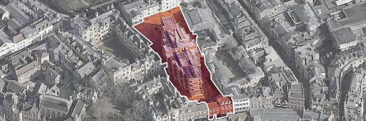
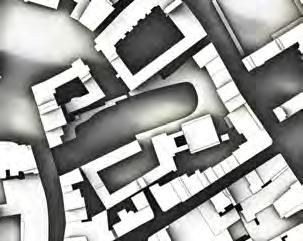
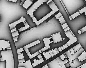
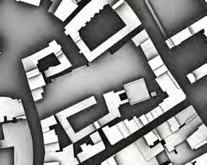
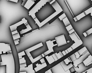
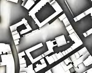
SITE urBan central camBriDge N Wolfson Building Trinity College 19-20 Trinity Street Winstanley Lecture Theatre Trinity College Whewell’s Court Trinity College All Saints Garden Market N Wolfson Building Trinity College 19-20 Trinity Street Winstanley Lecture Theatre Trinity College Whewell’s Court Trinity College All Saints Garden Market Protected Open Space Primary Shopping Area Primary Shopping Frontage Secondary Shopping Frontage City Wildlife Reserve Strategic District Heating Area camBriDge DeveloPment Plan Wolfson Building Trinity College 19-20 Trinity Street Winstanley Lecture Theatre Trinity College Whewell’s Court Trinity College All Saints Garden Market N Wolfson Building Trinity College 19-20 Trinity Street Winstanley Lecture Theatre Trinity College Whewell’s Court Trinity College All Saints Garden Market N
ancient ruins DiscovereD at central camBriDge

EXCAVATION
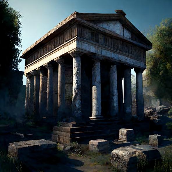
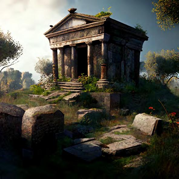
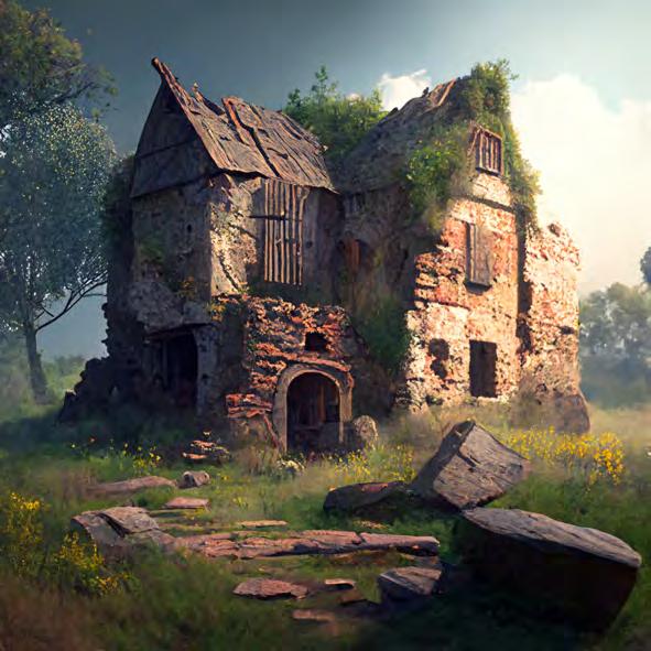
roman temPle mausoleum anD Burial 1:50 Natural Subsoil Iron Age Soil Primary Wall Primary Wall Burial spots Roman Road Roman Soil Mosaic Tiled Floor Tomb roman temPle Burial grounDs mausoleum Road-Ditch meDieval farmhouse 1:50 Medieval Garden Soil Medieval Pit Saxon Clay Floor Medieval Soil Roman Soil Primary Wall Collapsed Walls Medieval Floor stratigraPhy layers 1:100 -4.1m -3.5m -2.0m -1.2m GROUND LEVEL 0.0m 19-20 Trinity Street Underground Car Park Wolfson Building +3.0m site 1:200 Natural Subsoil [16] Iron Age Soil [15] Roman Soil [10] Medieval Soil [8] Early Modern Soil [2] Modern Soil [1] 1 2 5 15 16 13 7 10 8 3 12 6 4 11 9 14 Topsoil Medieval structure Foundation fill Soil deposites Roman structures Burial remains Foundation fill Natural sediments harris matrix Street 19 Trinity Street (Demolished) Underground Car Park (Demolished) [3] [5] [7] [4] [9] [14] [12] [13] [11] ROMAN TEMPLE MAUSOLEUM BRURIAL GROUNDS MEDIEVAL FARMHOUSE 1 E J O T U 10 19 28 37 Bedroom Larder Store Entry Living Space 2 11 20 29 38 3 12 21 30 39 4 13 22 31 40 5 14 23 32 41 6 15 24 33 42 16 25 34 43 17 26 35 44 18 27 36 45 D N S C H M R B G L Q A F K P Key Phase 1 Excavation Phase 2 Excavation Phase 3 Excavation Site Boundary Demolition Footprint Excavation Grid Archeological Ruins excavation Plan 1:200 meDieval farmhouse roman mausoleum m Djourney ai ruin concePts roman temPle Prompt: Medieval Farmhouse Ruins Archeology Prompt: small ancient roman rectangular mausoleum ruins surrounded by burial mounds 4k Prompt: Anicient Roman temple ruins archeology historic stratigraPhy
Early
The
EXCAVATION
archeological excavation
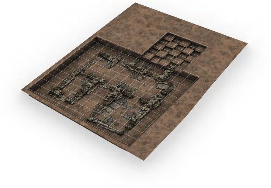
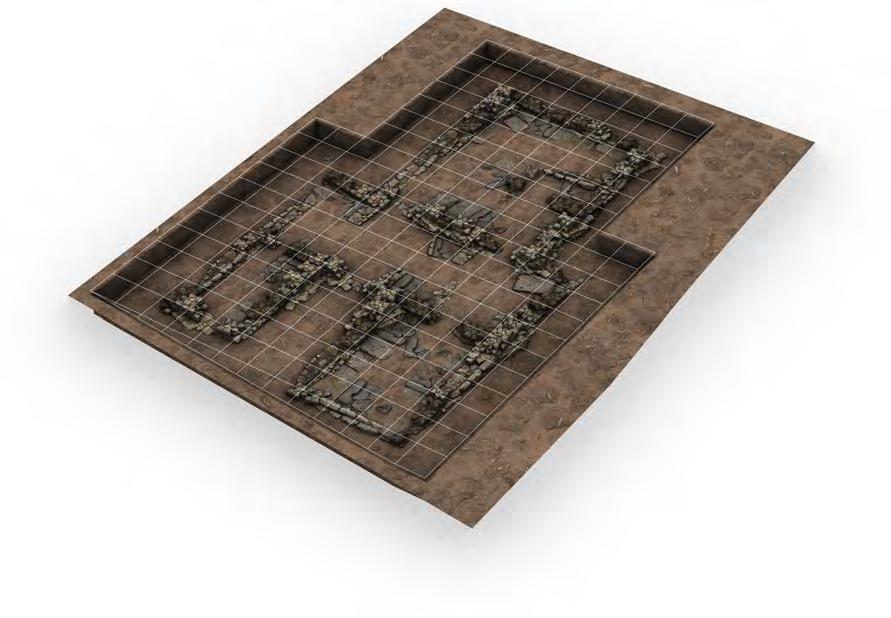
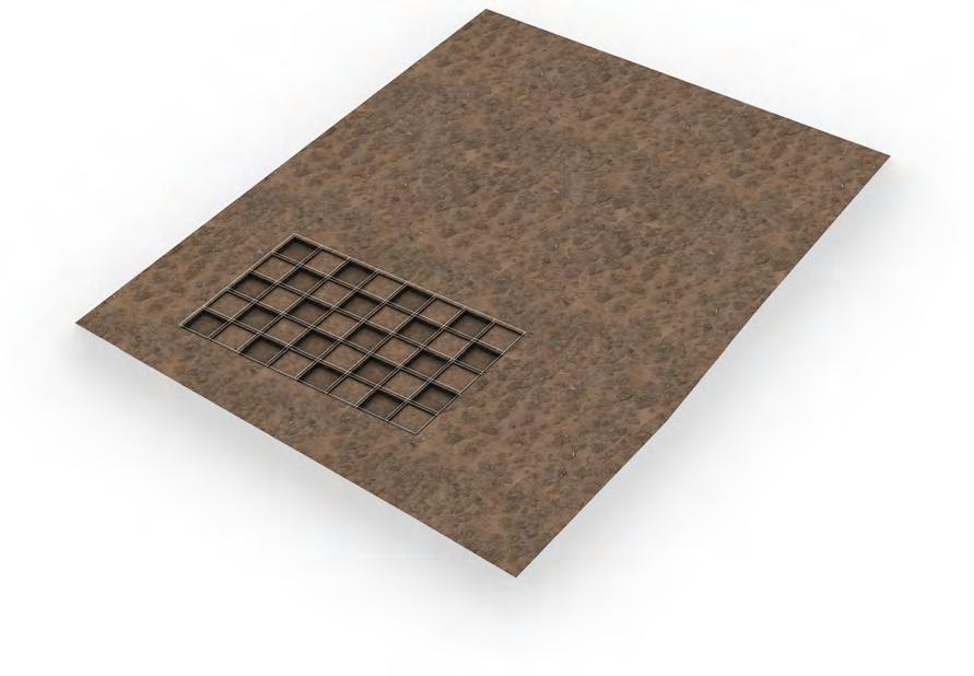
meDieval ruins’ excavation Process
After archeological evidence of large ruins are found, an initial dig grid is layed out.
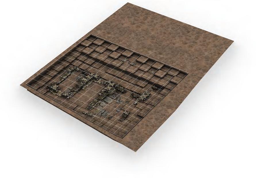
indications of a larger structure are uncovered, warranting and expanded dig.
A rudimentary plan of the ruins is devised based on the current discoveries, expanding the dig.
Excavation uncoveres most of the initial dig site but also shows walls reaching further out.
stage 1 stage 2 stage 3 stage 4
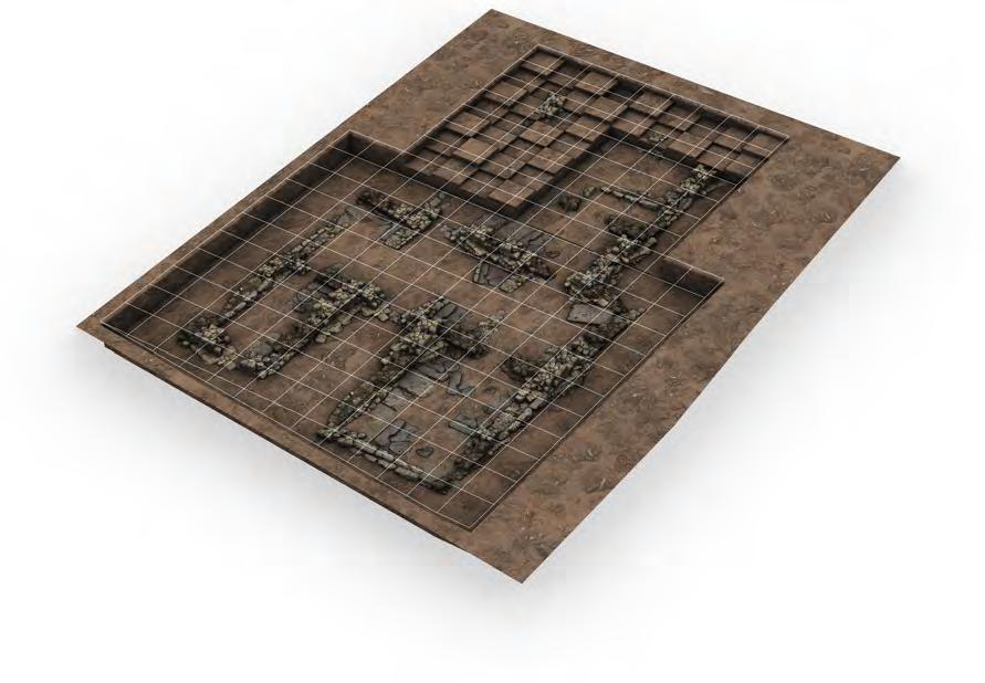
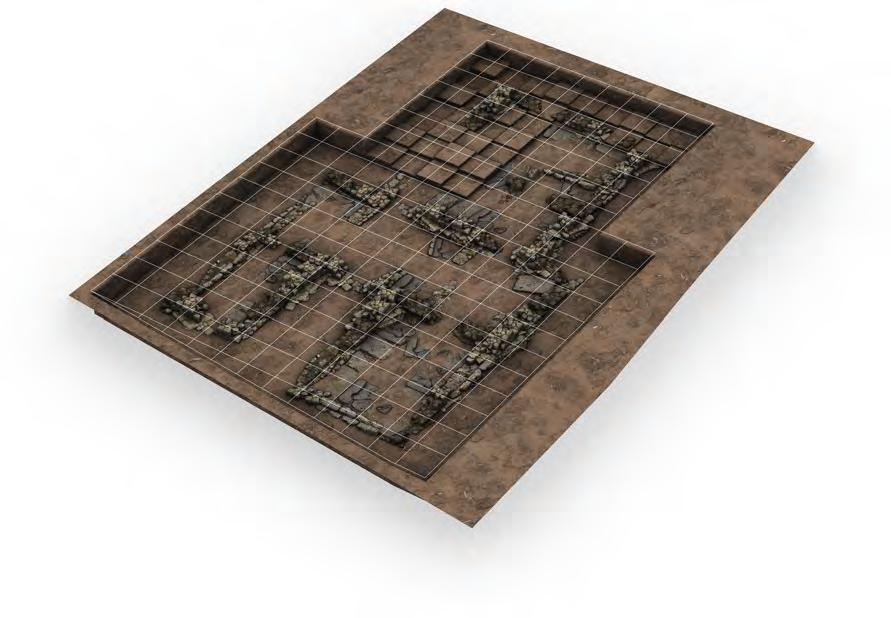
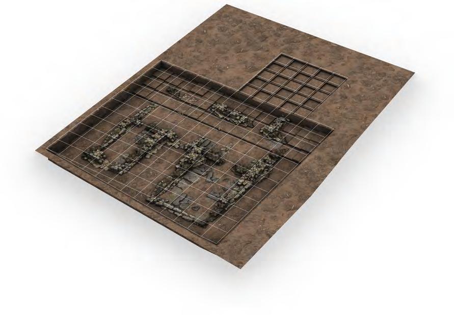
Bulk excavation finishes on the initial dig site, again revealing further expanse of the ruins.
The dig site is expanded in accordance with the ruins already uncovered.
The expanded dig site appears to cover the final extents of the ruins as analysis continues.
ruins are fully revealed, allowing for closer examination and cataloging of artefacts.
stage 5 stage 6 stage 7 stage 8
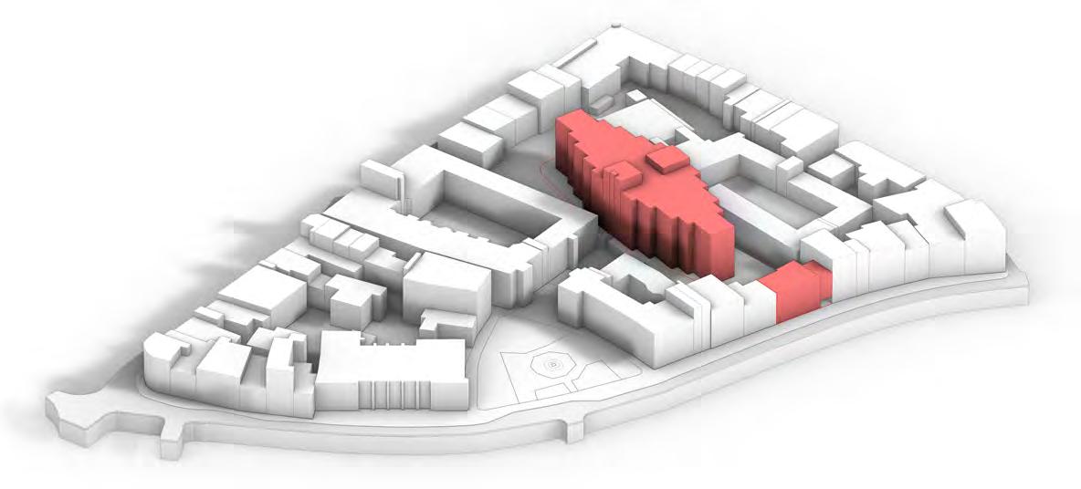
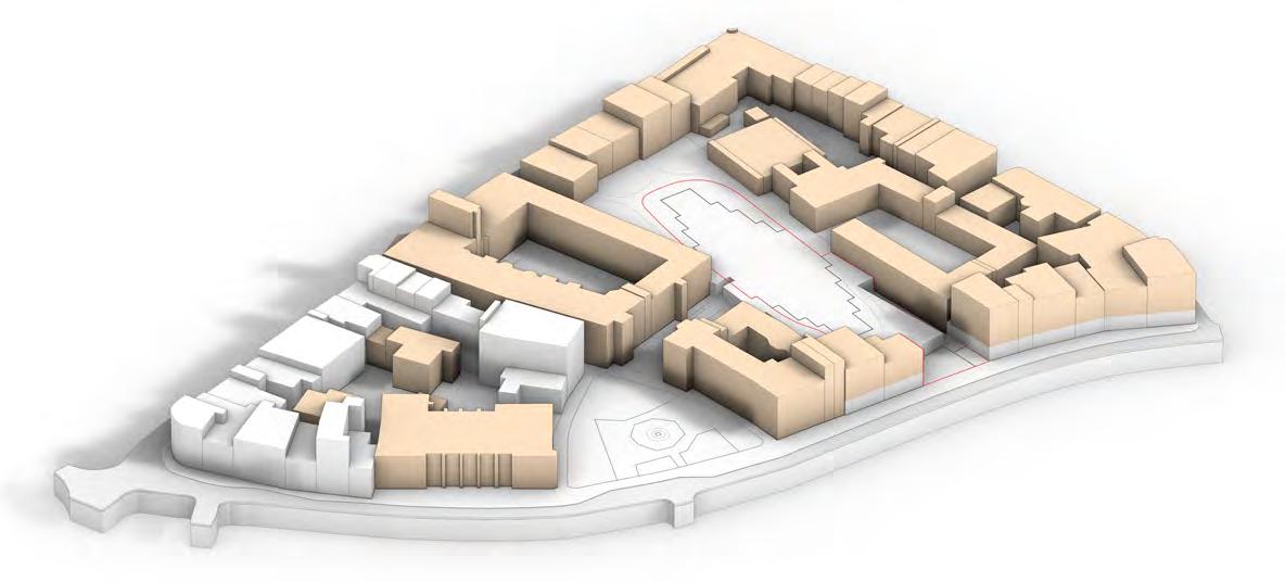 1. fire / reDuceD massing Extents of damage caused by the fire, resulting in the imposing massing of the existing Wolfson Building being demolished. The street front of Trinity Road also being broken by the damage.
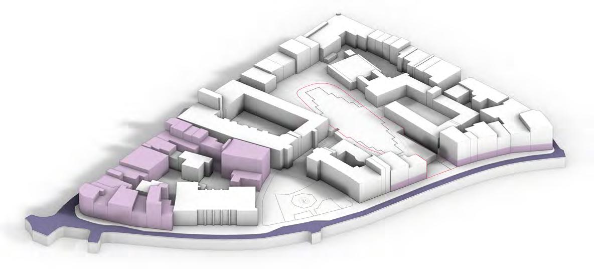
3. PuBlic aDjacencies Public retail spaces along the Trinity street front along with retail/residential buildings to the north, encouraging public approach to site via the high street road.
2. site levels
The site being located on an existing artificial platform (affording space for subterranean parking) creates a deeper level comparison in accounting for the differing levels of excavation.
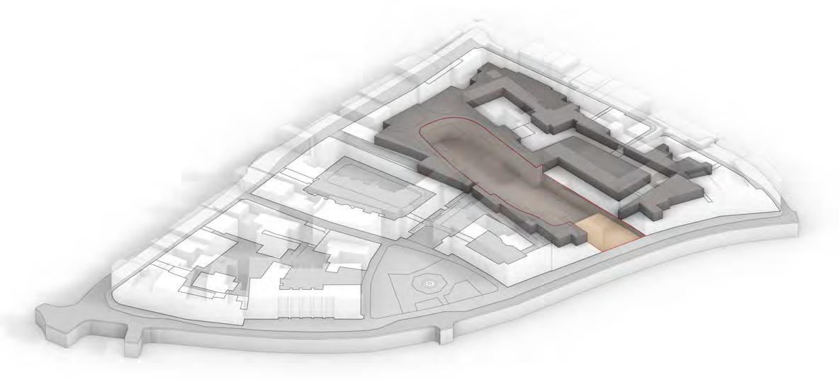
4. university aDjancencies
1. fire / reDuceD massing Extents of damage caused by the fire, resulting in the imposing massing of the existing Wolfson Building being demolished. The street front of Trinity Road also being broken by the damage.
3. PuBlic aDjacencies Public retail spaces along the Trinity street front along with retail/residential buildings to the north, encouraging public approach to site via the high street road.
2. site levels
The site being located on an existing artificial platform (affording space for subterranean parking) creates a deeper level comparison in accounting for the differing levels of excavation.
4. university aDjancencies
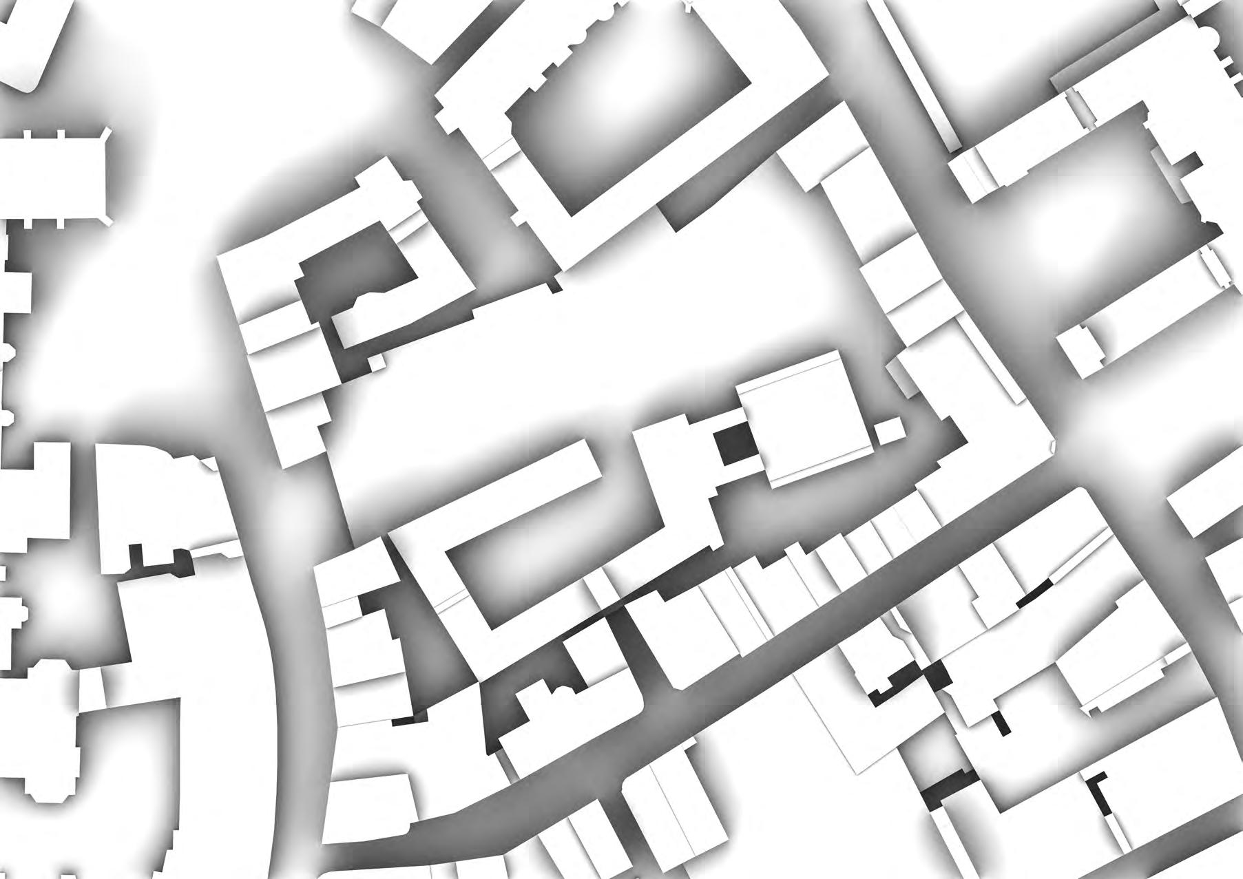
SITE surrounDing site analysis
Adjacent University of Cambridge educational facilities surrounding the site, with entry predominantly leading from private approaches at the upper platform level.
site conDitions + constraints

SITE
Grade I Listed Grade II* Listed Grade II Listed -3.0 -3.0 -3.0 0.0 0.0 0.0 0.0 Partial Overlooking -3.0 -3.0 0.0 0.0 0.0 0.0 Vehicle Access -3.0 0.0 0.0 -3.0 0.0 0.0 Existing Footprint -3.0 0.0 -3.0 -3.0 -3.0 0.0 0.0 -3.0 0.0 -3.0 -3.0 -3.0 0.0 0.0 -3.0 0.0 -3.0 -3.0 -3.0 0.0 0.0 Retained Footpath -3.0 0.0 0.0 -3.0 -3.0 0.0 0.0 -3.0 0.0 0.0 -3.0 -3.0 0.0 0.0 -3.0 0.0 0.0 -3.0 -3.0 0.0 0.0 Primary Public Road -3.0 0.0 -3.0 -3.0 -3.0 0.0 0.0 -3.0 -3.0 -3.0 0.0 0.0 -3.0 -3.0 -3.0 0.0 0.0 Residential Facades -3.0 0.0 -3.0 -3.0 -3.0 0.0 0.0 -3.0 0.0 -3.0 -3.0 0.0 0.0 0.0 0.0 -3.0 -3.0 -3.0 0.0 0.0 0.0 0.0 0.0 Feb Mar Apr May Jun Jul Sep Nov Aug Oct Dec Jan 2oC 8oC 8oC 0oC 25mm 10 C 50mm 20oC 75mm 30oC 40oC 100mm -10oC 0mm 23 C 12oC average temPerature anD PreciPitation Precipitation Mean Daily Max Temp Mean Daily Min Temp Hot Days Cold Nights clouDy sunny + PreciPitation Days Sunny Partly Cloudy Overcast Precipitation Days Feb Mar Apr May Jun Jul Sep Nov Aug Oct Dec Jan 5 days 10 days 15 days 20 days 25 days 30 days -10oC 1000 N S E W NE SE NW SW 750 500 250 0 WinD rose > 3 mph > 7 mph > 12 mph > 31 mph > 17 mph > 38 mph Weather charts WinD Direction North East South West Feb Mar Apr May Jun Jul Sep Nov Aug Oct Dec Jan 0% 100% 100% 0% 20% 80% 40% 60% 60% 40% 80% 20% clouD cover Clear (0-20%) Mostly Clear (20-40%) Partly Cloudy (40-60%) Mostly Cloudy (60-80%) Overcast (80-100%) Feb Mar Apr May Jun Jul Sep Nov Aug Oct Dec Jan 0% 100% 100% 0% 20% 80% 40% 60% 60% 40% 80% 20% average Daily hours of sun Feb Mar Apr May Jun Jul Sep Nov Aug Oct Dec Jan 8 hours 4 hours Sunlight hours Monthly Average
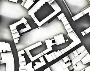

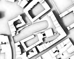
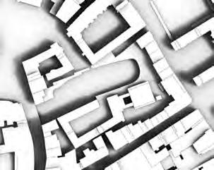
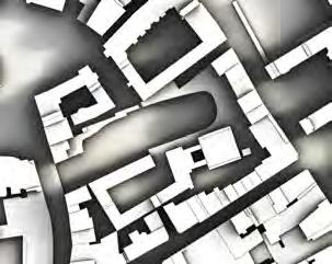


SITE solar context sun Path KEY Summer Solstice Sunrise Range Winter Solstice Sunset Range Equinox 00-02 hrs Annual Variation 12-14 hrs 03-05 hrs 06-08 hrs 18-20 hrs 09-11 hrs 21-23 hrs 15-17 hrs 10 20O 30 40 50O 60O 70O 80O 12 09 12 15 09 06 03 00 N S E W 18 15 21 09:00 12:00 15:00 sectional stuDies summer solstice - 21/06/2023 06:00 09:00 12:00 15:00 18:00 Street Level +3m Street Level -3m sectional stuDies 09:00 12:00 15:00 Winter solstice - 22/12/2023 STREET LEVEL +3 m 06:00 09:00 12:00 15:00 18:00 STREET LEVEL -3 m
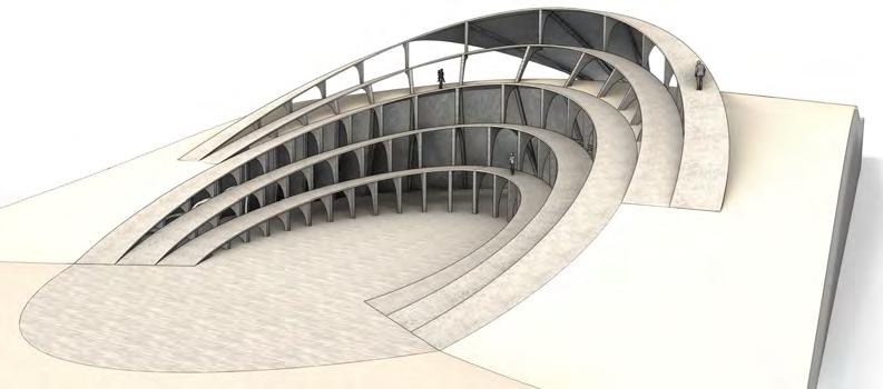
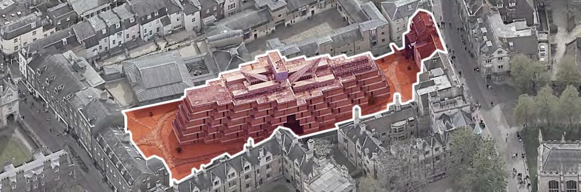
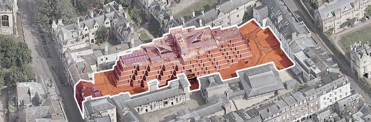
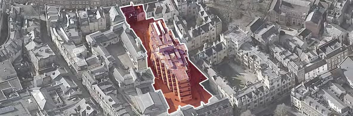
SITE site oPPortunities anD massing loWer level massing Key Site Boundary Ruins Footprint Upper Level Public Space Excavation Space Auxilary Space Public Entry Private Entry Excavation Material Delivery Drop-Off Building Grid Structural Points Key uPPer level massing Site Boundary Ruins Footprint Lower Level Public Entry Delivery Drop-Off Building Grid Structural Points Public Space Biodiversity Uplift Auxilary Space oPPortunities Key Site Boundary Sight Lines Ruins Footprint Foot Access Site Alignment Upper Level Biodiversity Uplift Vehicle Access
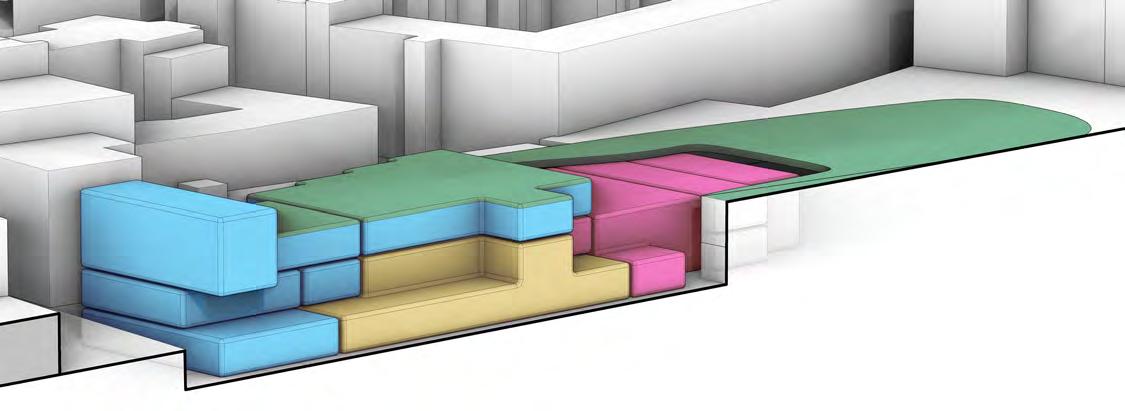
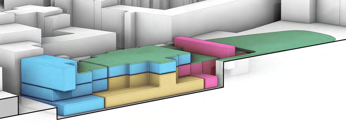
PROGRAMME on-site massing KEY Public Exhibition Private Archeology Main Excavation Planted Space initial BlocK massing height + site form aDjustment segmenteD Division removing massing Planes interior/exterior exPresssion
site massing strategies
Sub-proposal development to accommodate the excavations and allow safe level change access and transit of artefacts. Access via ground level.
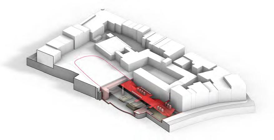


Providing shelter over the excavations to enable work to proceed uninhibited and preventing damage to the unearthed ruins and artefacts.
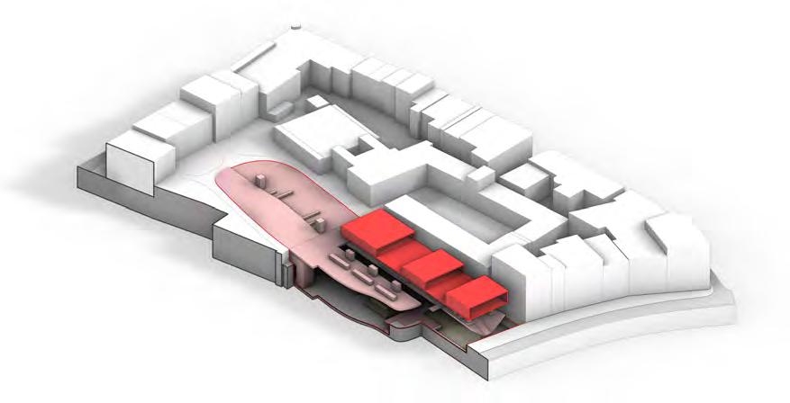
3. EXHIBITION - PUBLIC
Inhabiting the space with a public display of the excavation and artefacts. Public entry at the street front and university via upper platform.
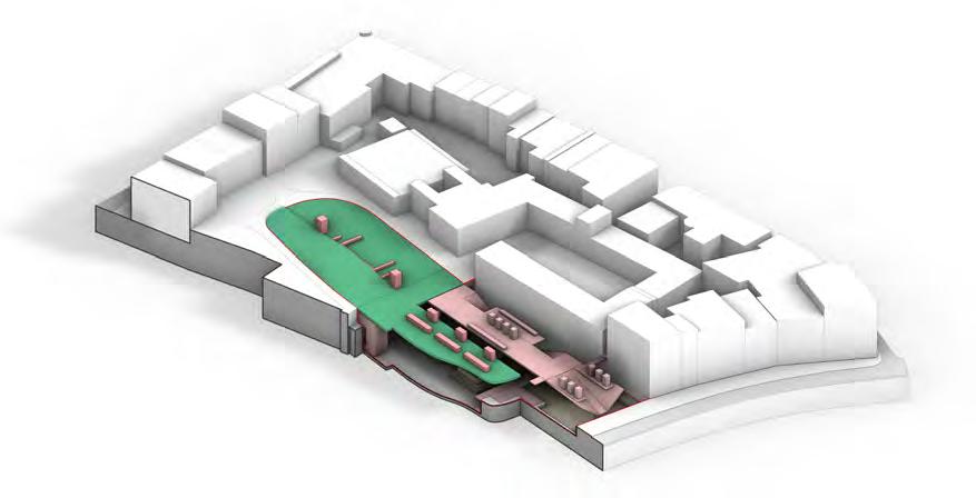
Egress from the exhibition onto a shared park space with few exhibits, used by both the public and university staff and students.
5. EDUCATION - PRIVATE
Educational facilities for archeology students housed in a private upper level. Not exceeding the neighbouring building heights and spans.
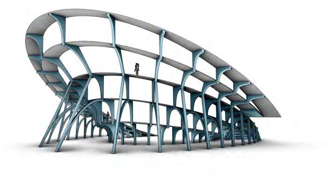
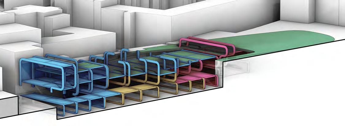
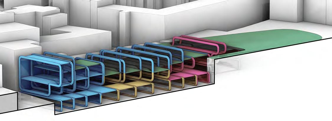
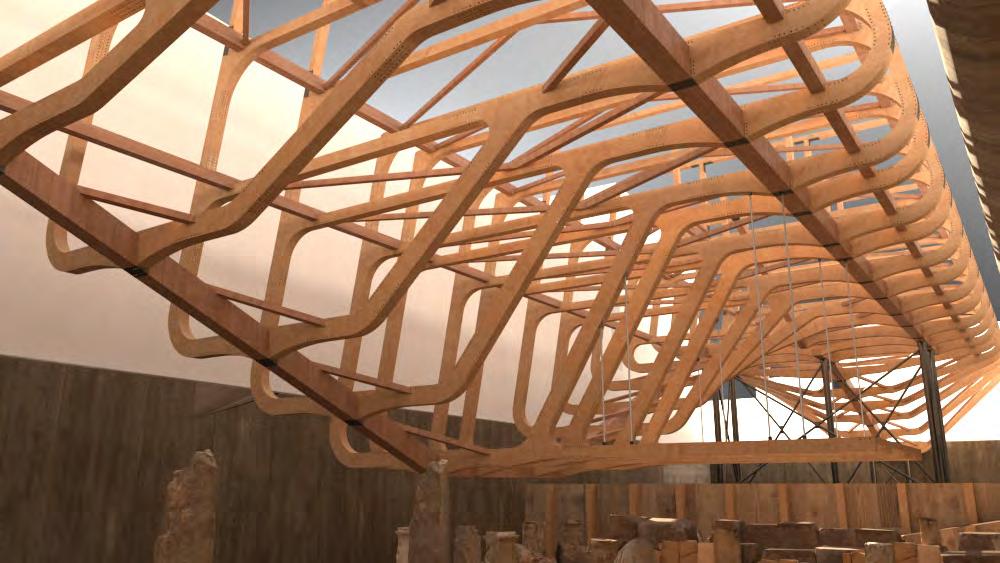
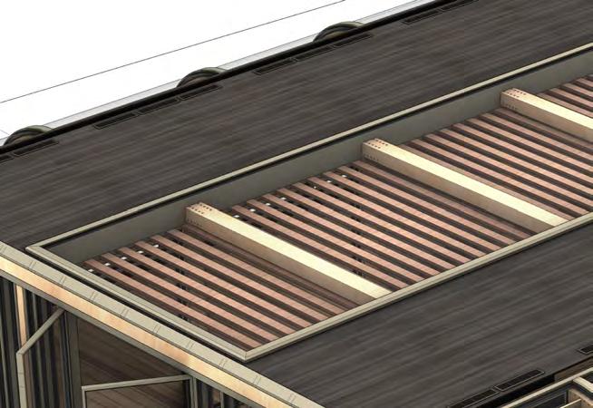
6. SPANNING RIBBED STRUCTURE
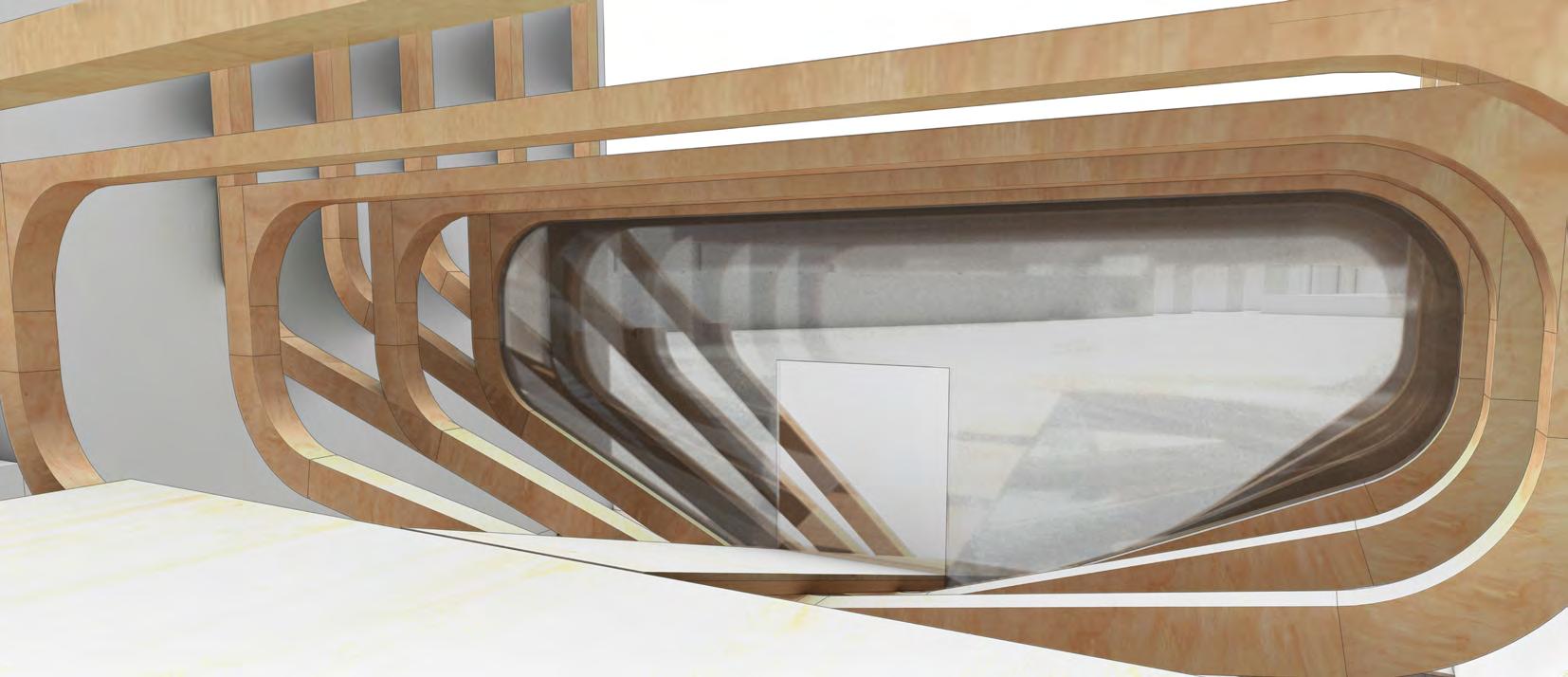
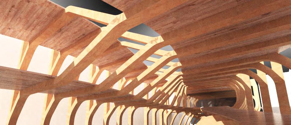
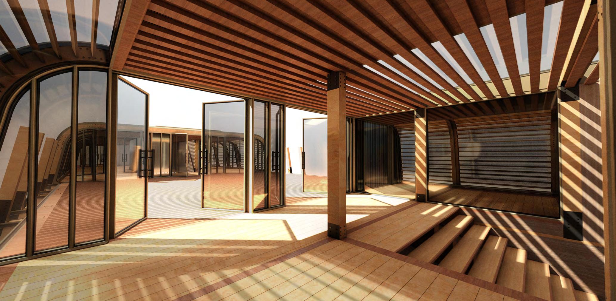
The buidling form being divided into a ribbed truss-like structure, allowing light to permeate and views onto the ruins between the rib gaps.
PROGRAMME
1. ruins + excavation
4. LANDSCAPING - SHARED
2. SHELTER
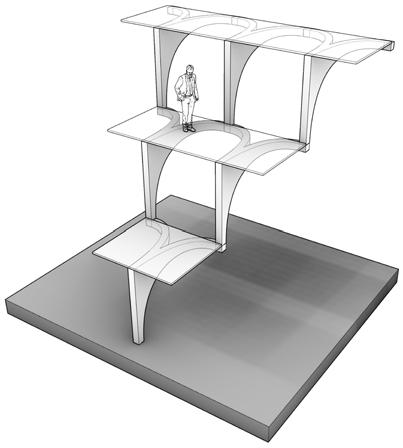
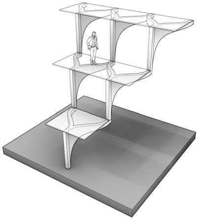
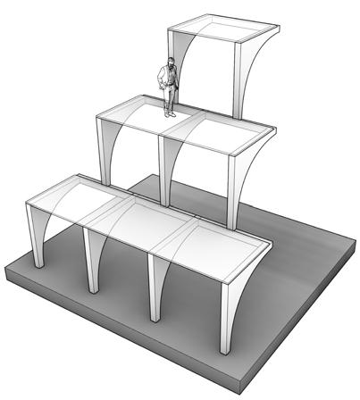
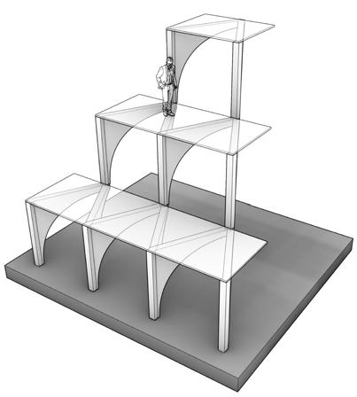
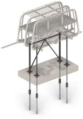
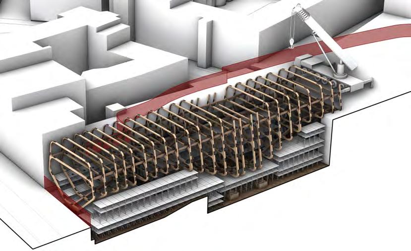
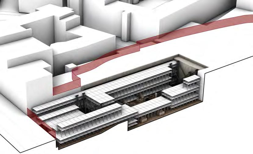
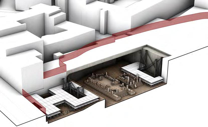
PROGRAMME assemBly + excavation stages stage 6 - PuBlic intergration stage 7 - massing reDuction stage 4 - exhiBition exPansion stage 5 - full excavation stage 2 - sheltering excavation stage 3 - Dig exPansion / exhiBition stage 0 - existing site / Demolition stage 1 - initial Dig / founDations
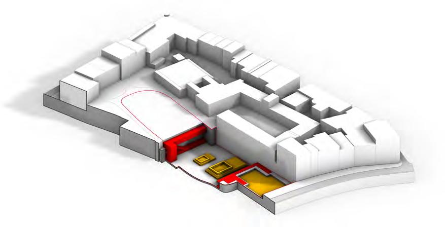
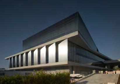
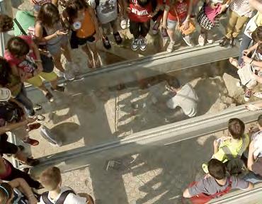
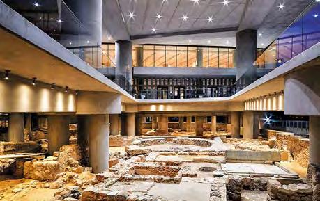
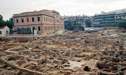
neW acroPolis museum, BernarD tschumi
Set at the foot of the Acropolis in Athens, Greece, the museum is built over an ancient Greek forum; displaying the ruins through openings and glass flooring while the arefacts excavated are displayed within.
stage 5 - full excavation
As the excavation site has fully uncovered the ruins, any arifacts are transferred either to storage elsewhere or into the public exhubution spaces. These spaces are wholly separated from the dig site, with views down onto it below to observe the ruins still under protection.
stage 6 - PuBlic intergration
After the most sensitive atifacts and material is removed, the excavation site is opened up to the public, who are able to participate in light touch finishing excavation. The public spaces are also expanded to encourage further participation in the fully opened site.
stage 7 - massing reDuction
Prior to dismantling, the structure is reduced as the artifacts are relocated, merging more into the landscape. The excavation site is now covered under glass flooring to allow the public to walk among the ruins while it is determined whether they are to remain or also be relocated.
significant ProPosal assemBly stages
PROGRAMME
EXCAVATION PRIVATE ENCLOSED EXHIBITION PUBLIC OPEN EXHIBITION PUBLIC GREEN ROOF PUBLIC GARDENS PUBLIC
ENTRANCE PRIVATE
ARCHEOLOGIST
EXCAVATION PUBLIC ENCLOSED EXHIBITION PUBLIC OPEN EXHIBITION PUBLIC GREEN ROOF PUBLIC GARDENS PUBLIC ARCHEOLOGIST ENTRANCE PUBLIC
ENCLOSED RUINS PUBLIC OPEN EXHIBITION PUBLIC ROOF GARDENS PUBLIC GARDENS PUBLIC ENTRANCE PUBLIC
RIBBED TIMBER MASSING STUDIES FORM GENESIS


MASSING Street entrance FOrMS


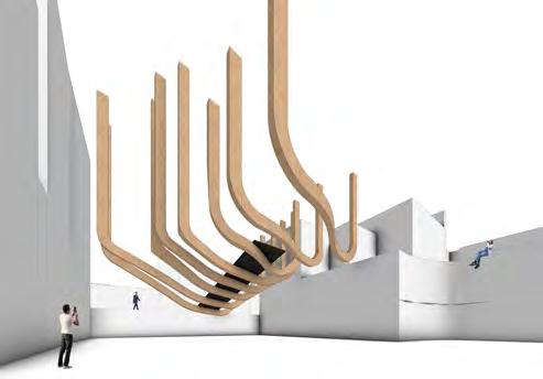
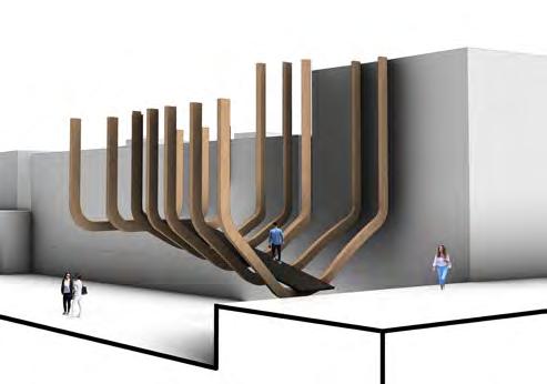

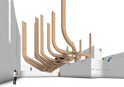
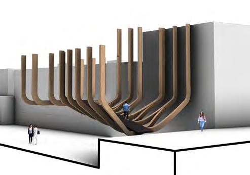
MATERIAL rib interSectiOn StudieS

BUILDING FORM Street entrance FragMent

BUILDING FORM early Structure develOpMent

MATERIAL early Structure develOpMent

BUILDING FORM early Structure develOpMent
BUILDING FORM reduced FraMe FOrMS

BUILDING FORM reduced FraMe FOrMS
MASSING level change StudieS

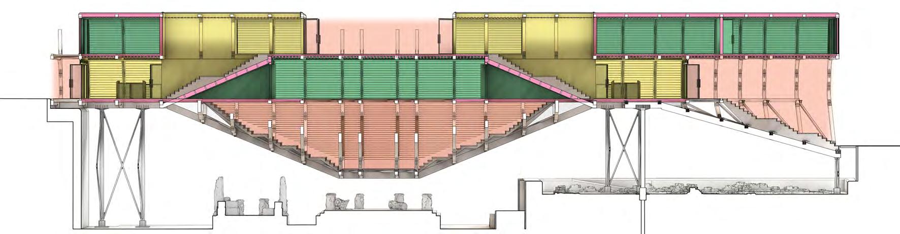
Spatial MaSSing ARCHEOLOGICAL PARK EXCAVATION OVERLOOK PUBLIC ENTRY PUBLIC DIG MEDIEVAL EXCAVATION ROMAN EXCAVATION ARCHEOLOGICAL ROOMS ARTEFACT EXHIBITION Public Exhibition Private Archeology Main Excavation Planted Space SectiOnal arrangeMent ARTEFACT EXHIBITION ENCLOSED ROMAN EXCAVATION SHELTERED ENTRY PUBLIC ARRIVAL UNENCLOSED ENTRY DIG STORE SHELTERED MEDIEVAL EXCAVATION SHELTERED 5m 5m 5m 5m 5m 5m 5m 5m 5m 5m 5m 5m -2.5m 0.0m +2.5m +5.0m +7.5m ARCHEOLOGICAL PARK UNENCLOSED CATALOGUING ENCLOSED STUDY ROOM ENCLOSED LECTURE THEATRE ENCLOSED Spatial relatiOnShipS Unenclosed leading to enclosed • Some artefact dislays • Small reception • Reduced active excavation Guided public dig access • Educational study Unenclosed but sheltered • Active, ongoing excavation Minimal built disruption Equipment + artefact work surfaces • Unenclosed but sheltered Temporary artefact store • Equipment store Initial artefact labelling Secure access • Personal storage threshold Single access points Enclosed, controlled environment Examination + cataloguing Storage + preperation for transit / display Student research and study Examination worktops Space for educational events Adaptable theatre seating Dedicated for archeology Fully enclosed Display of artefacts Main circulation space Natural + artificial lighting • External landscaped space Display of some artefacts + university exhibitions • Space for university events arteFact exhibitiOn Medieval excavatiOn rOMan excavatiOn dig StOre private entry catalOguing Study rOOM lecture theatre archeOlOgy garden public entry Via grand stair Via stair + lift Via stair + lift Via stair Key View Key View Trinity Street University Campus PROGRAMME Spatial OrganiSatiOn
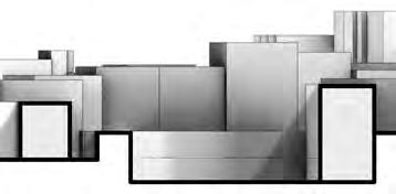
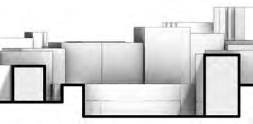
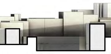
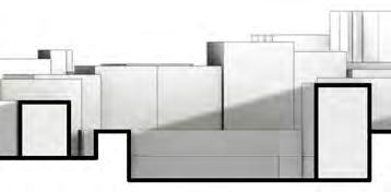
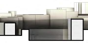
1. siTe ProPorTion mAssing
Determining the general proportions of the structure relative to neighbouring buildings and site levels; matching the length of the adjacent southern campus building while setting back from the street front.
2. eLevATing sTrucTure
Raising the structure in response to the site levels, separating it from the dig site and meeting the elevated rear level; keeping the building height in line with those neighbouring so as not to become too overbearing.
3. resPonding To excAvATion
Varying the street front and mid levels of the structure for the flow of circulation to enable differing views onto the excavations below.
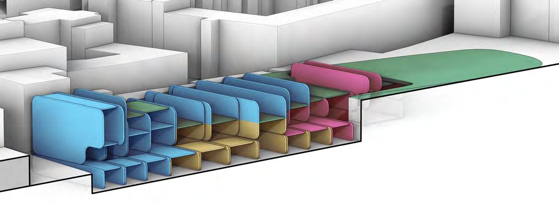
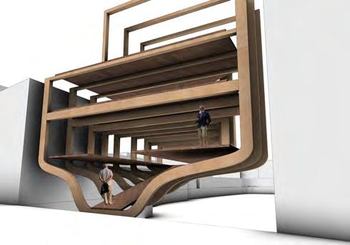
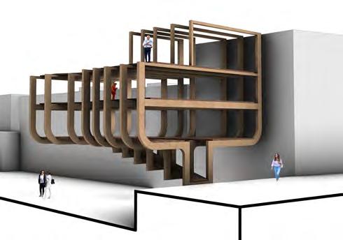
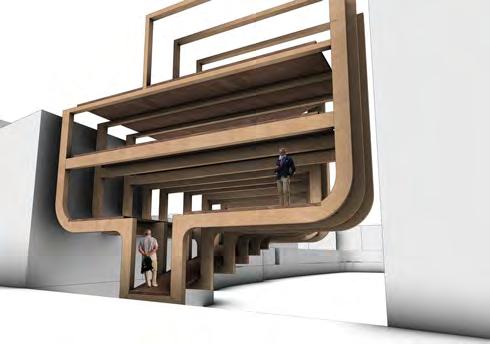
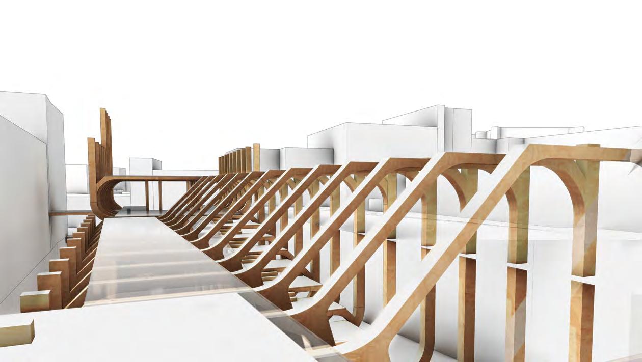
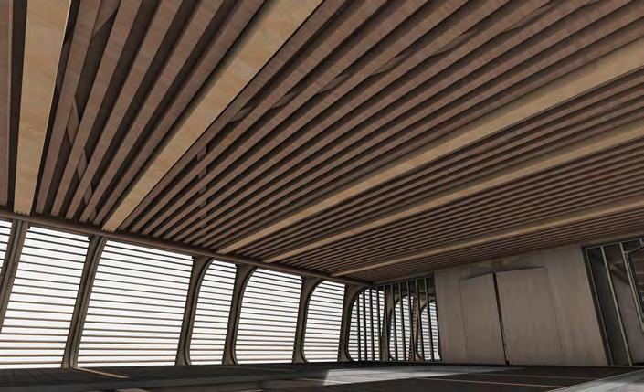
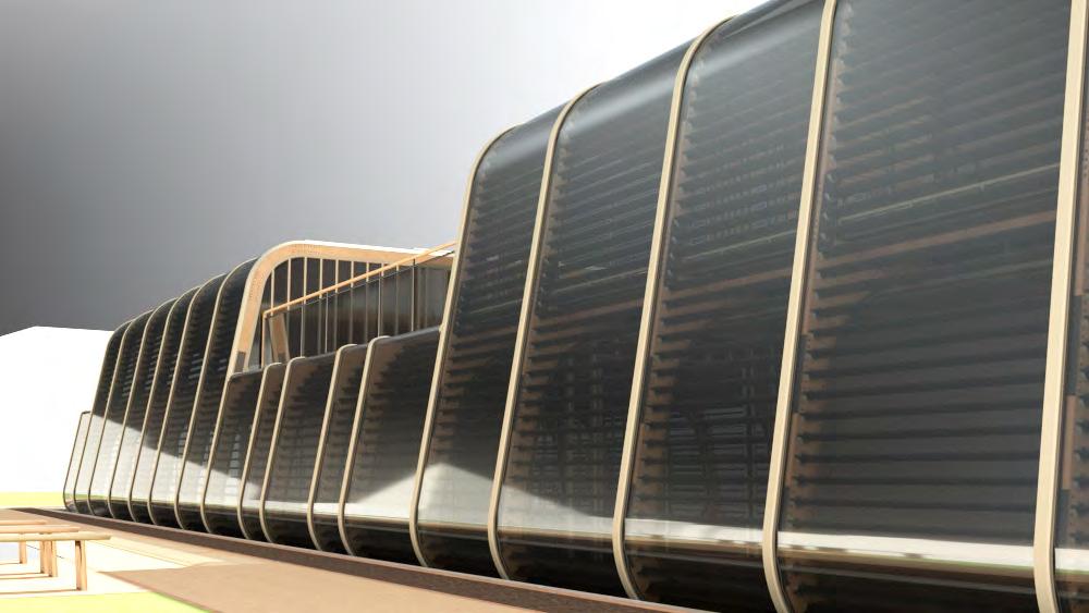
4. ribbed Tr AnsPArencies
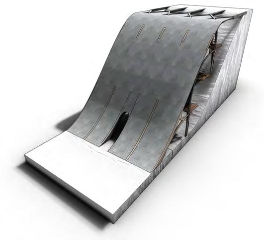
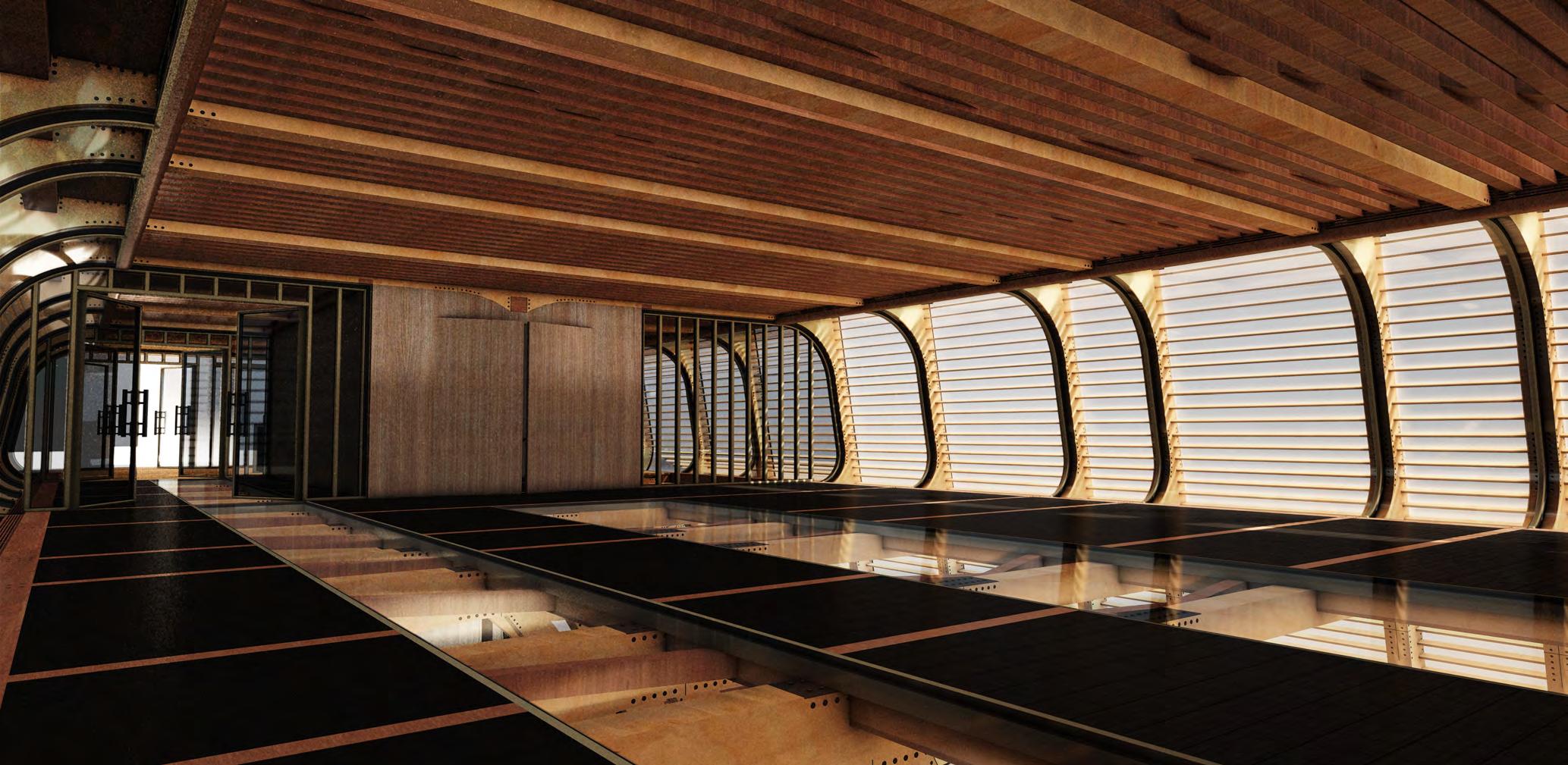
Ribbing the structure along the east-west alignment to enable greater sunlight to permeate internally, whilst in keeping with the aspiration for a “levitating” structure that gives transparency to the dig sites and ruins.
5. sPATiAL Arr AngemenT
Determining internal and external spaces in regards to circulation progression, adjacencies and relation to site. Setting back the envelope enclosure from the street whilst still sheltering with an overhang above.
design genesis
BUILDING FORM
PRIVATE PUBLIC PUBLIC
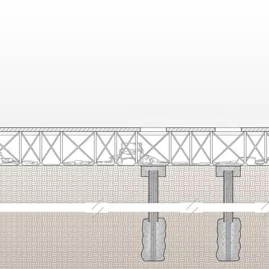
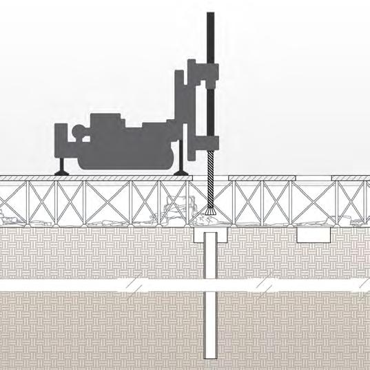
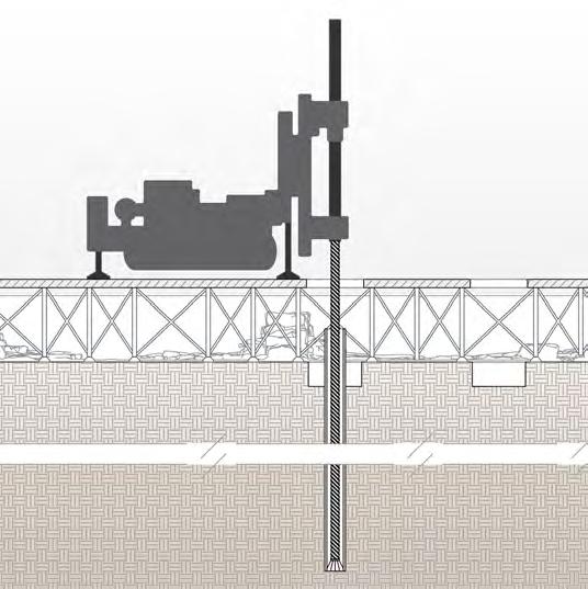
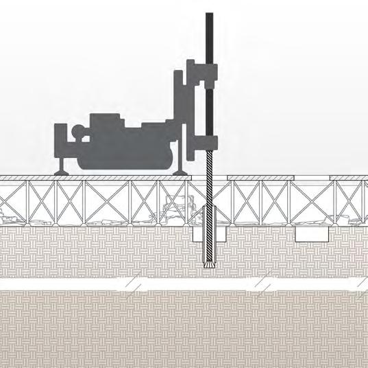
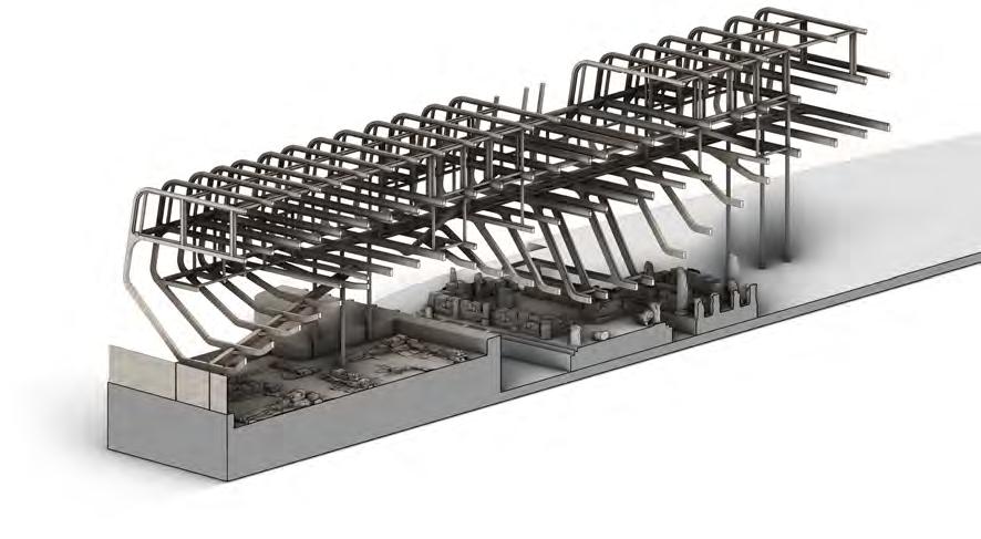
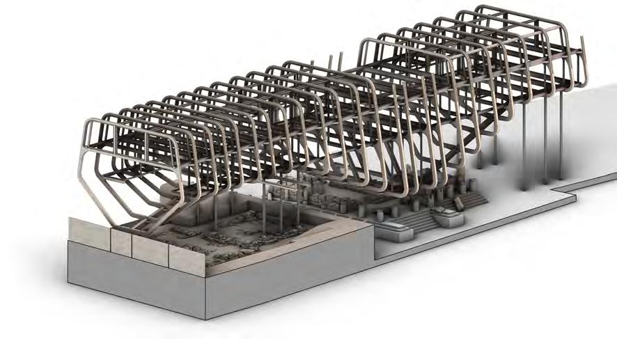
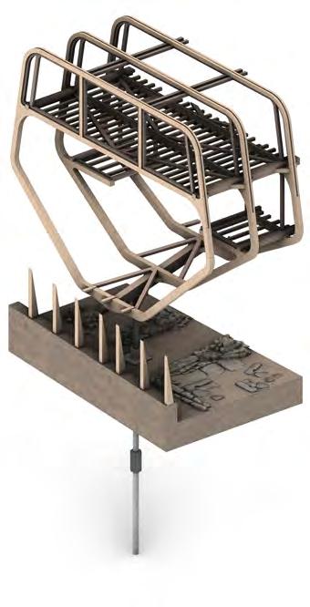
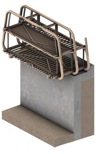
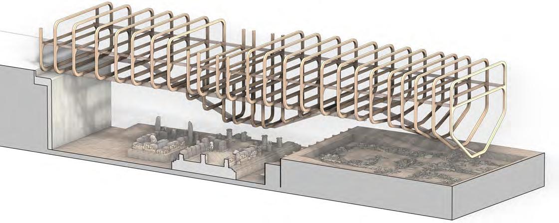
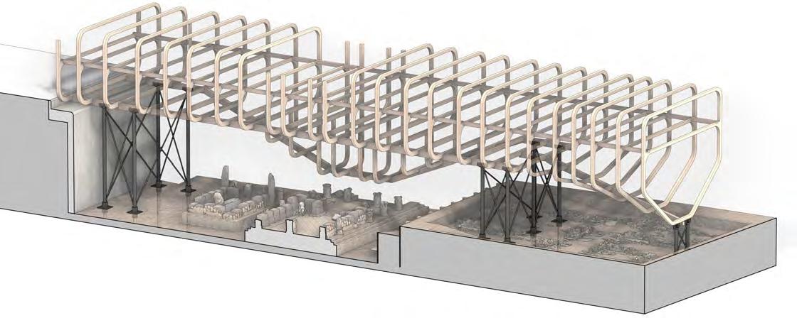
STRUCTURE Structural Strategy 1 2 3 4 5 6 ribbed FraMeS Sequence Transfer of dead loads through primary structure Horizontal transfer of loads Live Loads Lateral beams and foundation columns Secondary structure Primary frame structure 7 8 12 11 10 9 16 15 14 13 17 18 19 20 21 22 23 24 lOng SectiOn Strategy 1 1 2 3 4 4 3 2 Transfer of dead loads through primary structure Dead loads incurred from ground Transfer of dead loads through vierendeel truss Natural wind/snow/rain loads Live loads Timber retaining wall - 300x200mm verticle piles Micropile concrete foundations Structural steel columns - 300mm di Lateral timber beams - 400x300mm 1 2 3 4
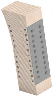
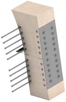
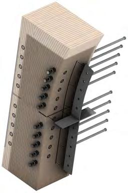
microPiLe FoundATions
STRUCTURE
1. s Te PrePer ATion
2. iniTiAL driLLing
3. comPLeTe driLLing
4. removAL oF driLL biT
5. grouT + rebAr
6. FurTher inJecTion
7. comPLeTed P Le
8. PiLLAr AssembLy


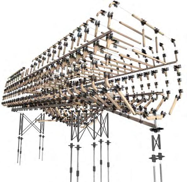
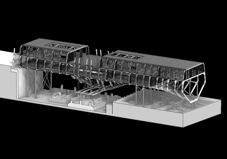
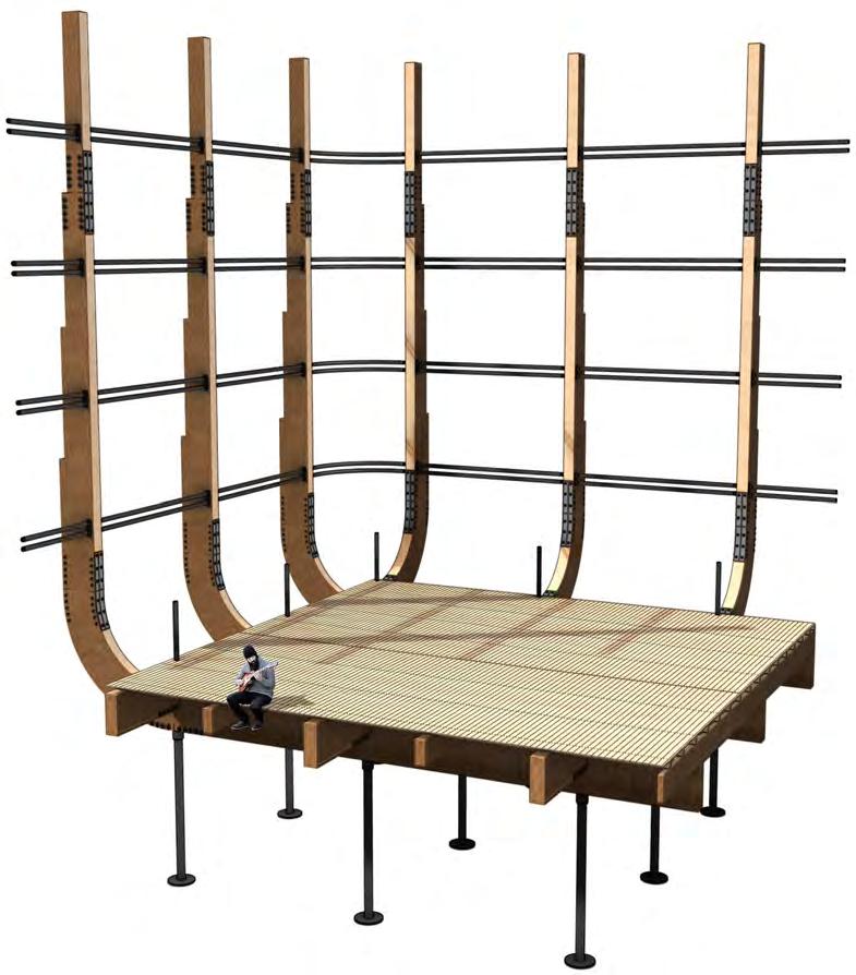
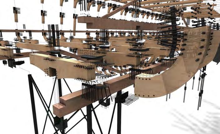
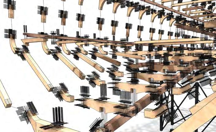
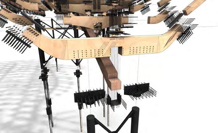
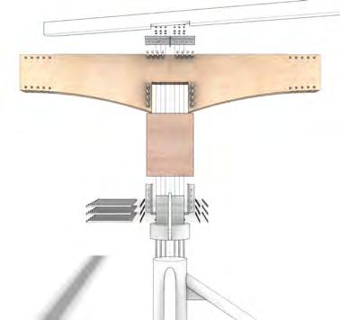
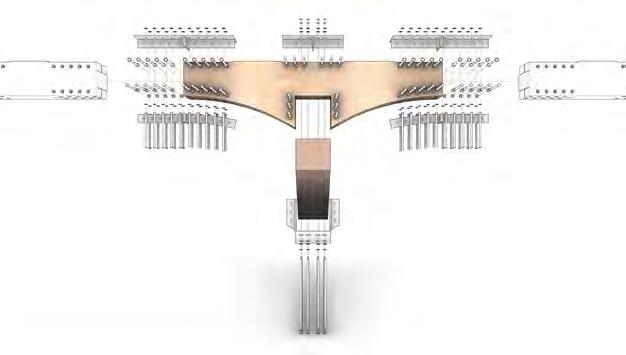
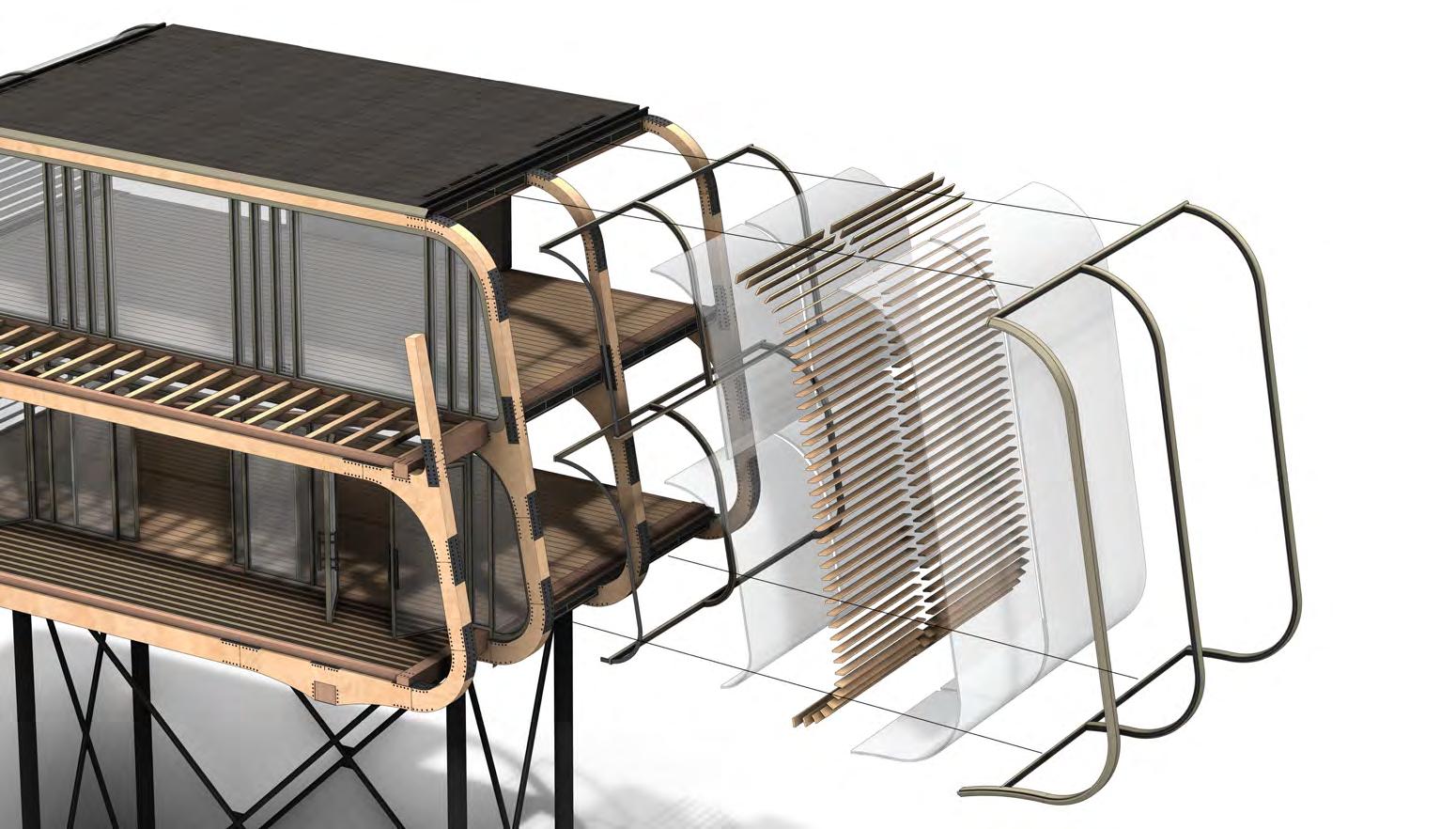
STRUCTURE Fr AgmenTs Fr AgmenT sTudies sTreeT enTr Ance reAr cAmPus enTr Ance cenTr AL muLT -LeveL Timber comPonenTs 150 x 200mm 150 x 200mm 175 x 200mm 150 x 200mm 300 x 400mm 250 x 200mm 150 x 200mm 100 x 100mm 50 x 100mm sTrucTure breAkdown LATer AL br Acing inTernAL Fr Aming FLoor + ceiLing JoisTs micro-PiLe FoundATions + sTeeL coLumns LATer AL beAms sTrucTur AL Fr Ames sTrucTur AL skeLeTon
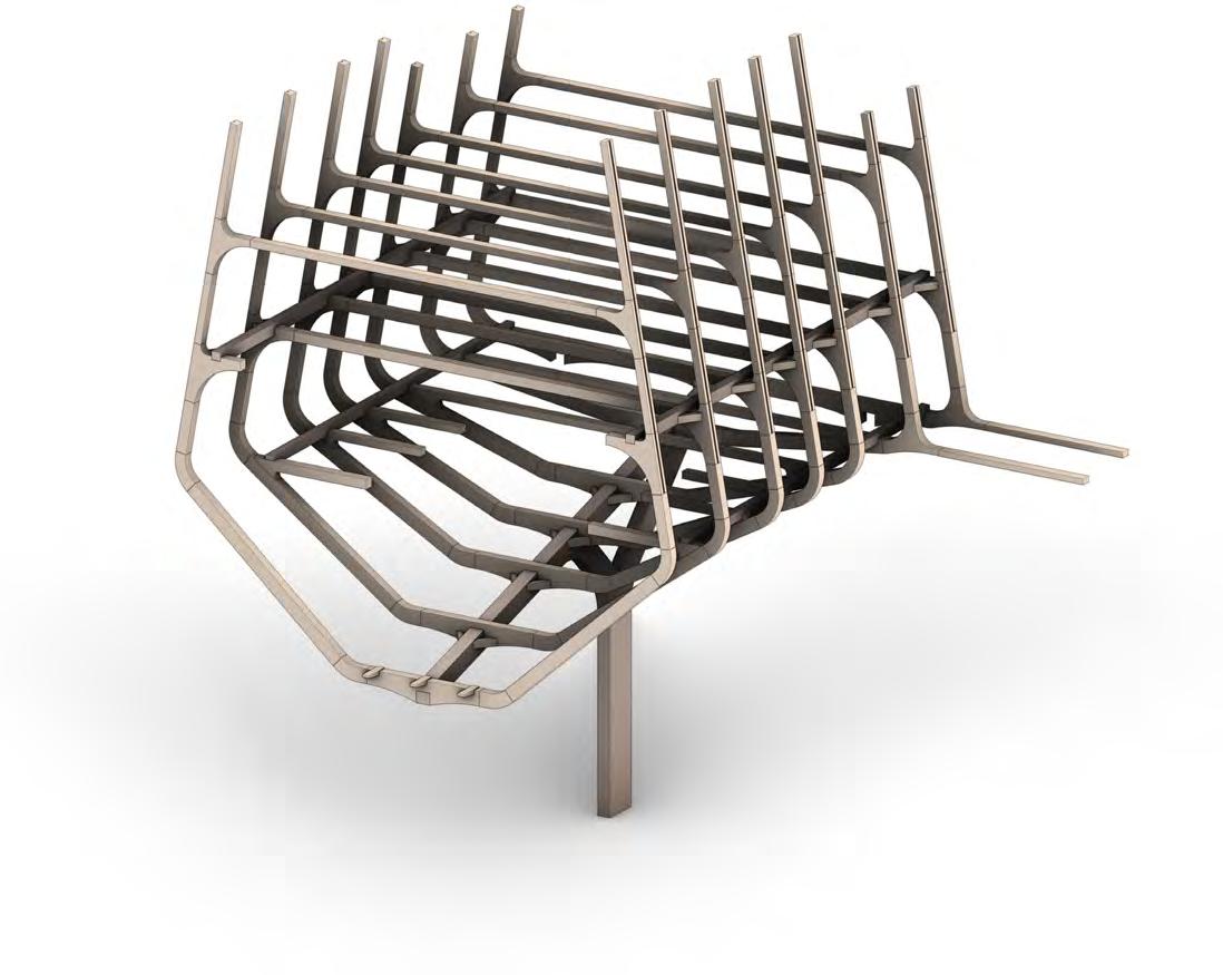
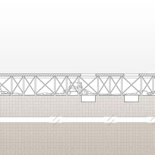
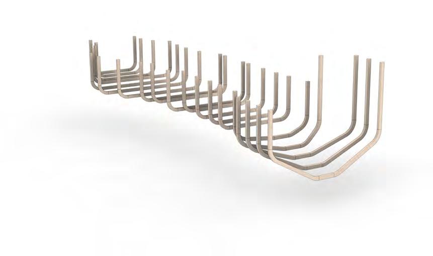
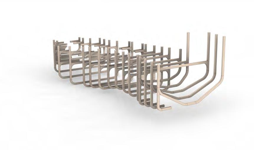
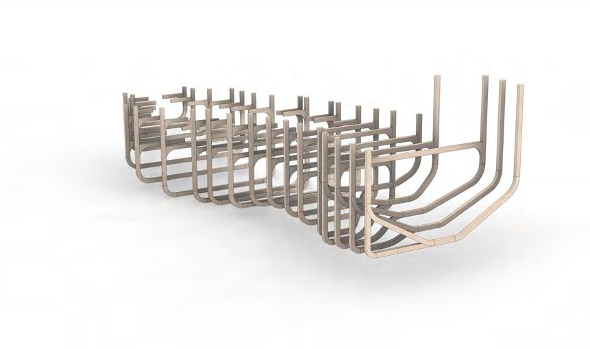
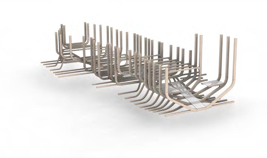
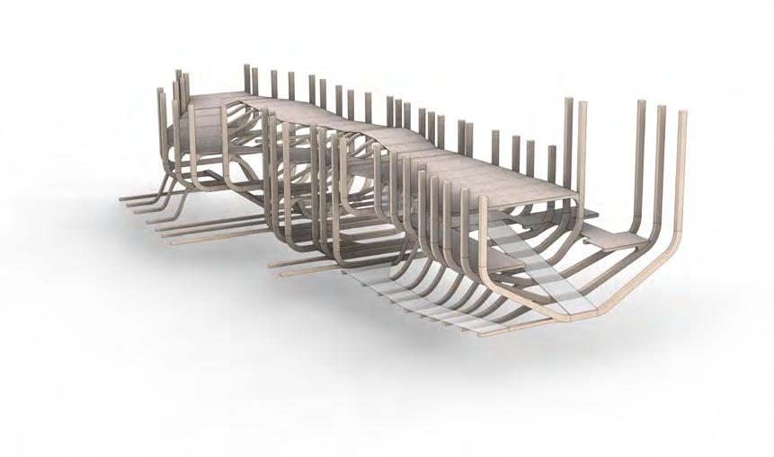
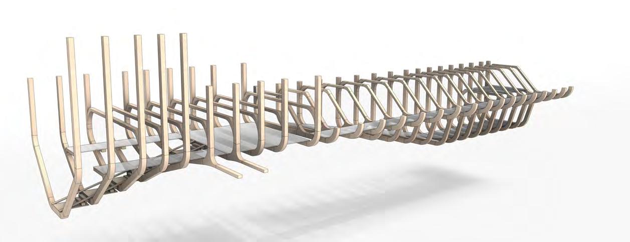
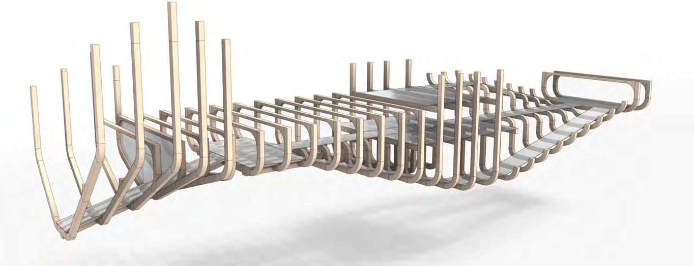
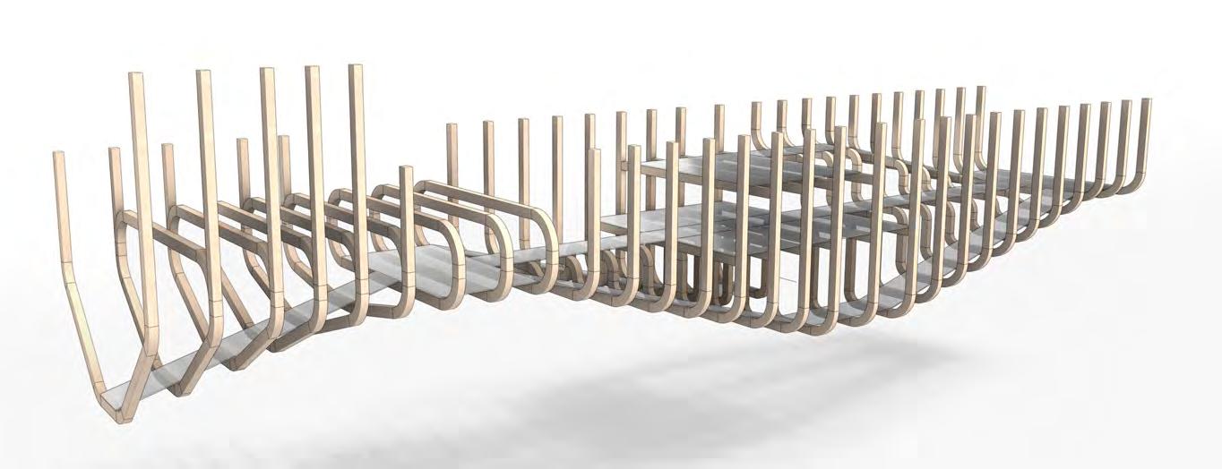
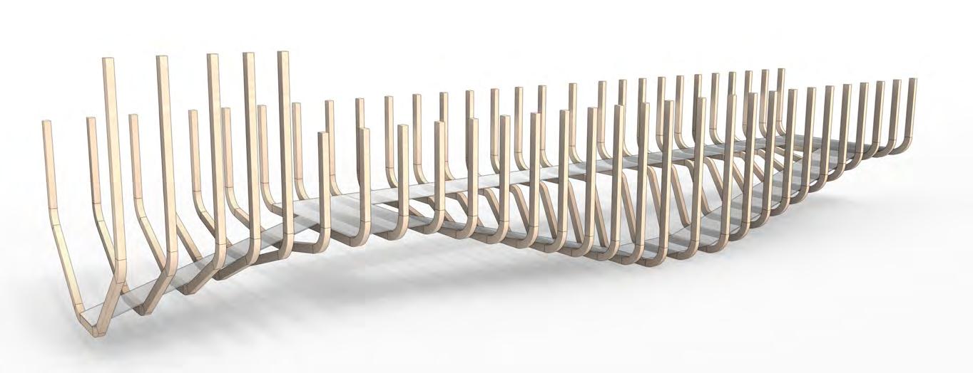
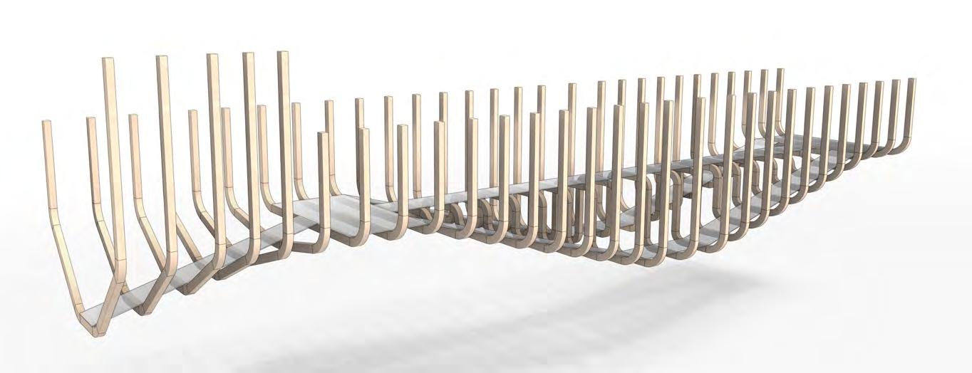
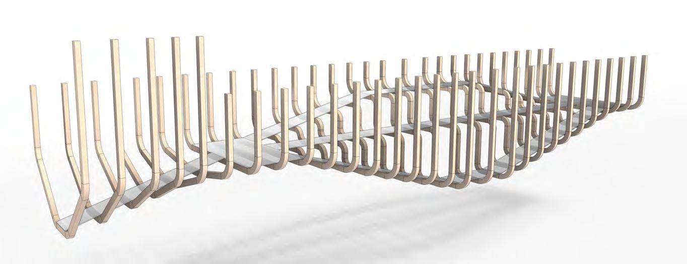
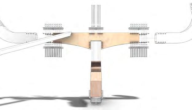
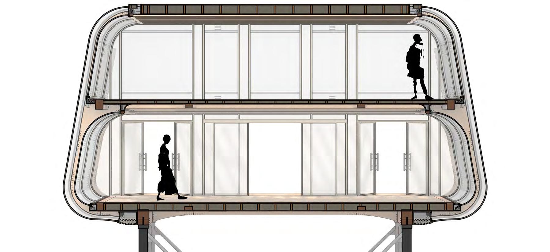
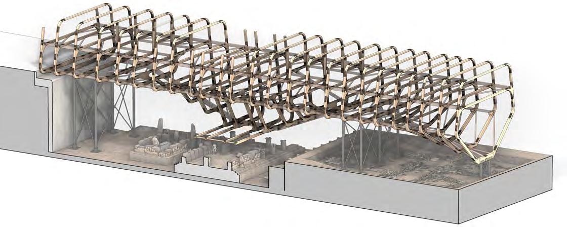
Truss
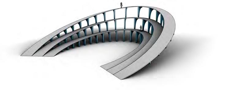
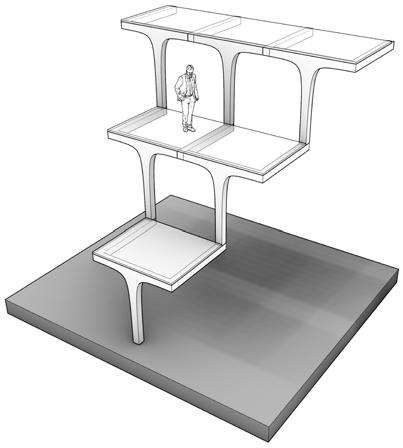
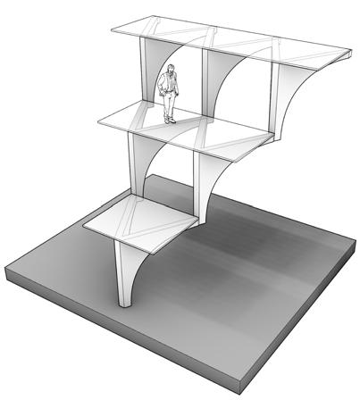
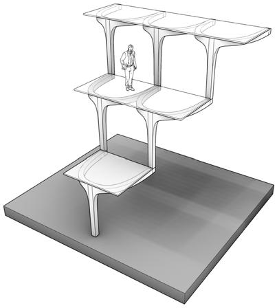
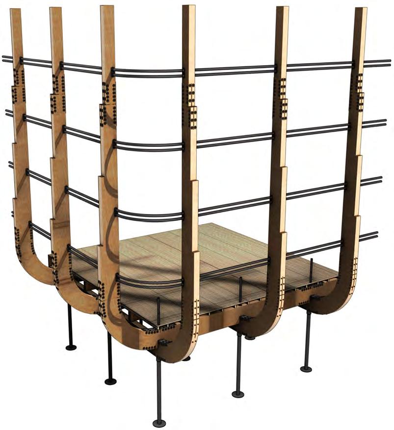
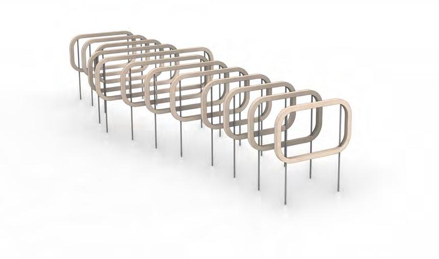
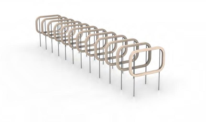
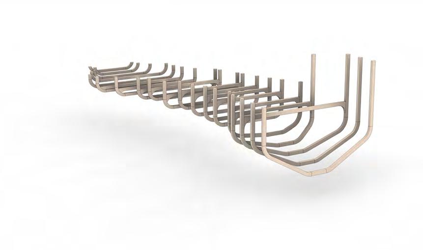
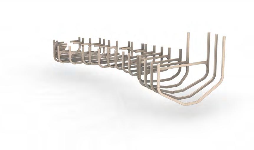
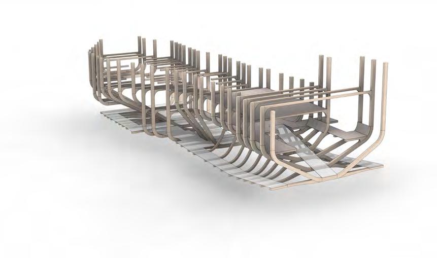
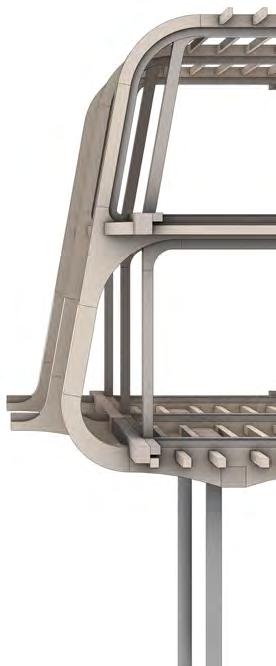
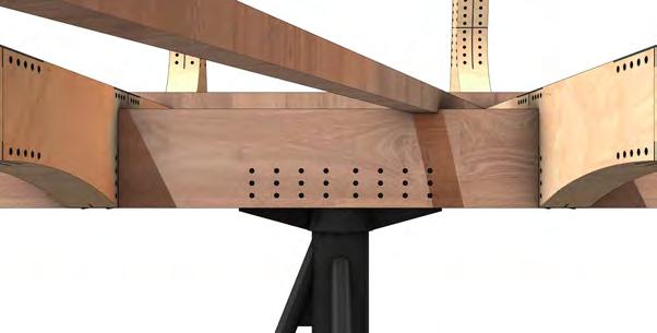
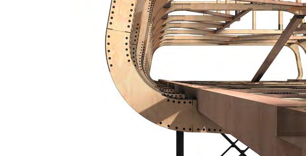
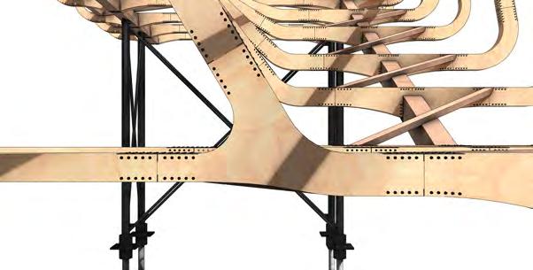
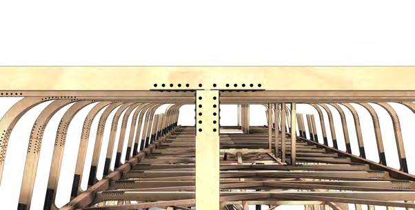
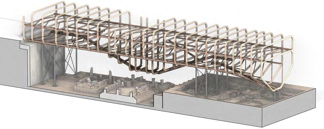
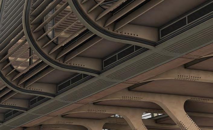
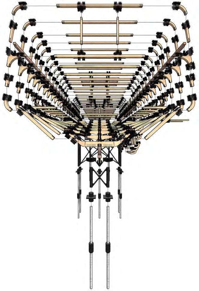
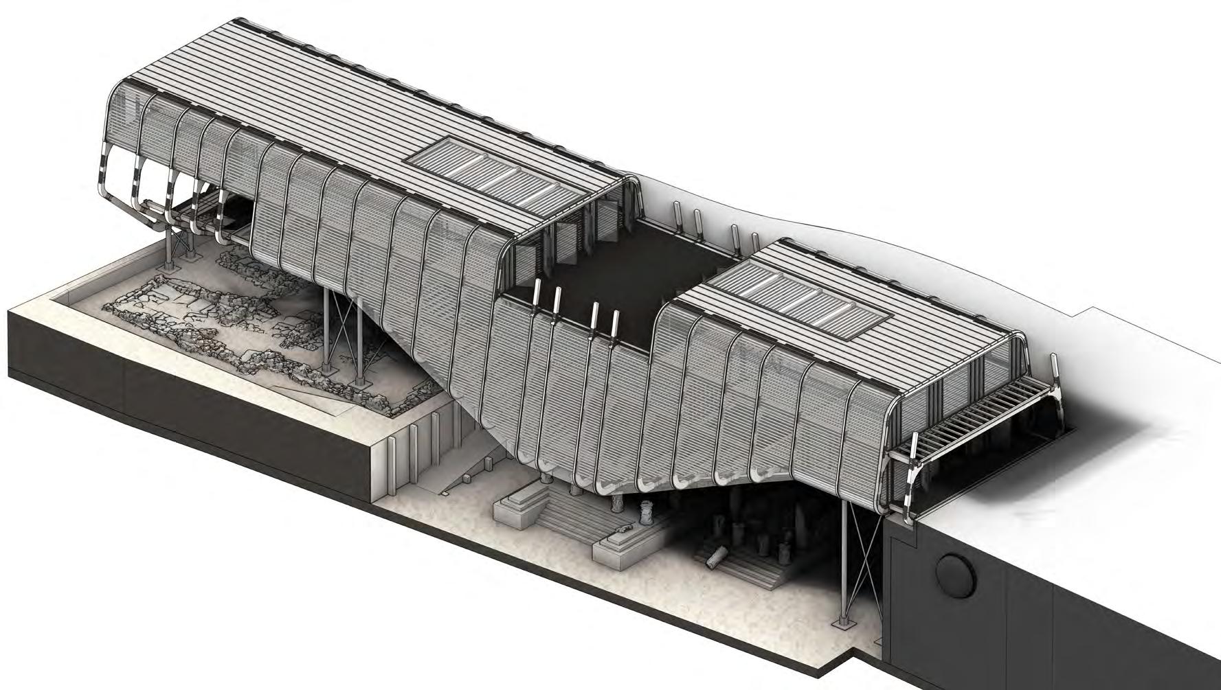
The truss structure is comprised of 25 frames spaced at varying intervals, each of which share a common mid level form that is supported by lateral beams on each side. and cross bracing at floor and ceiling levels.
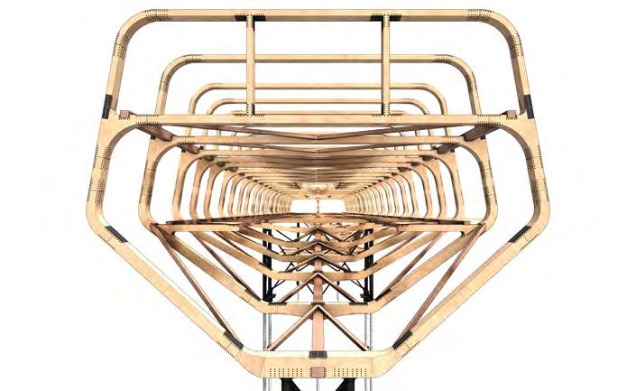
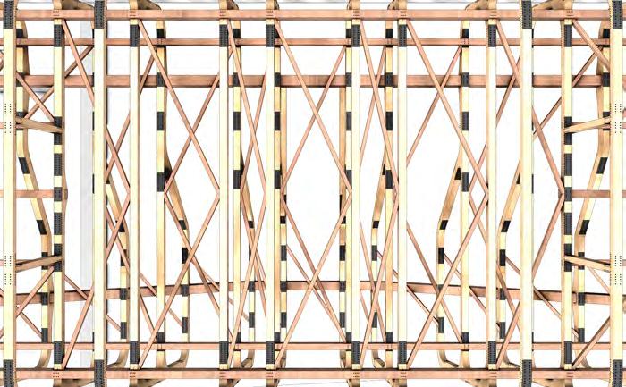
The inclining street facing segment of the structure is supported at its base by a single large beam that is supported by pillars at each end. All else of the structure is supported at the base by two large lateral beams, one on either side, that bear and distribute the entirety of load from the the structure above.
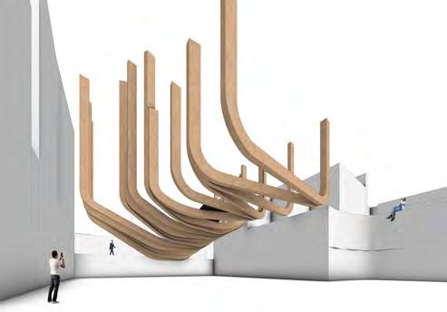
Where the mid section dips to a suspended platform, the base lateral beam is crancked to fit the form. To support this form change, the micrpile foundation pillar have been placed on each end, allowing this dip to be cradled between them.
sTrucTur AL sTr ATegy
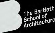
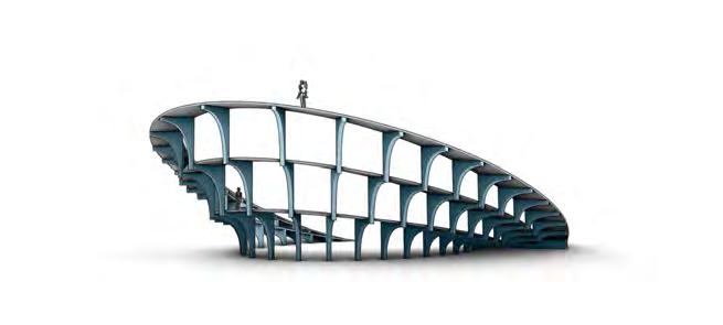
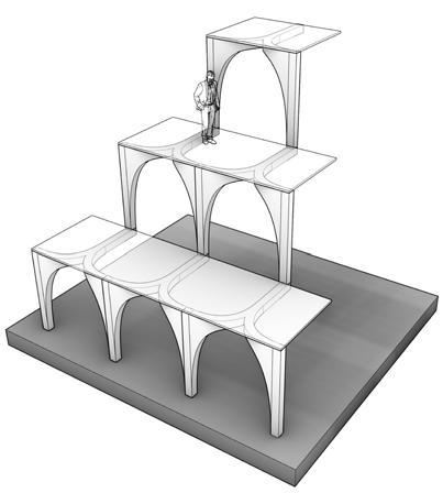
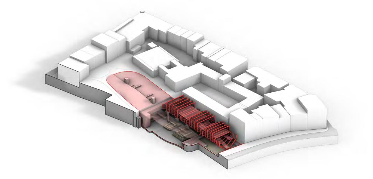
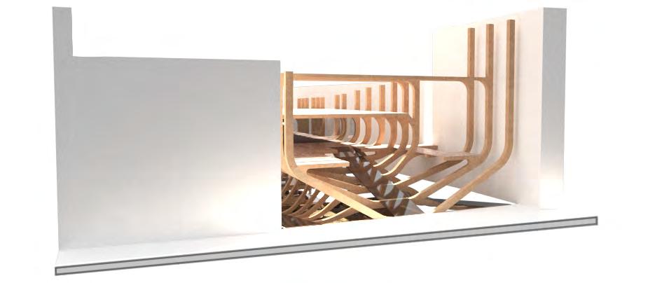
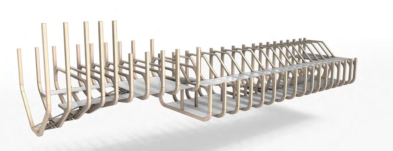
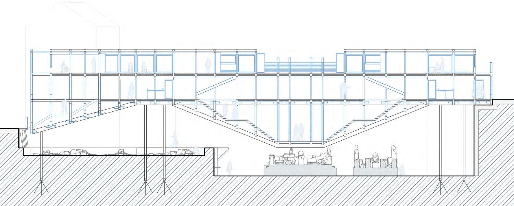
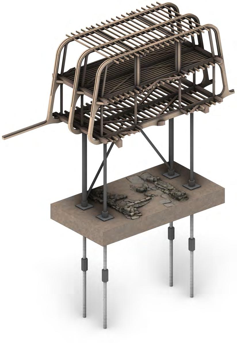
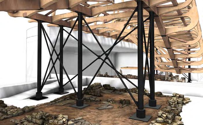
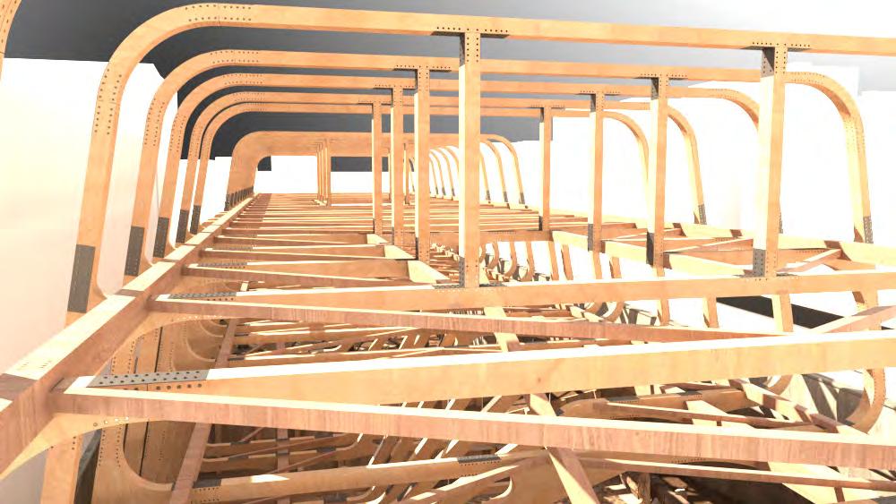
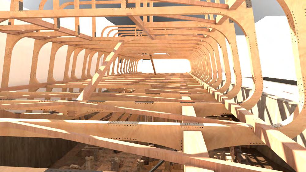
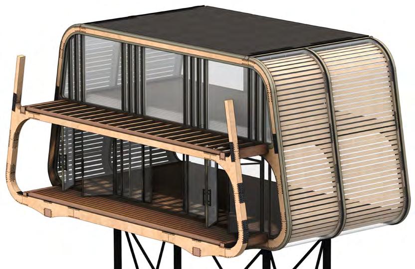
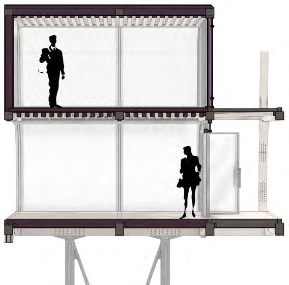
The primary structural design is comprised of a truss system that is supported at three intervals, elevating it above the sensitive archeological excavation site. The principle of this choice of structure being to minimise landing points while still enabling the enclosed programmatic spaces to be supported. These landing points too being minimised in use of micropile foundations located only where archeologically possible.
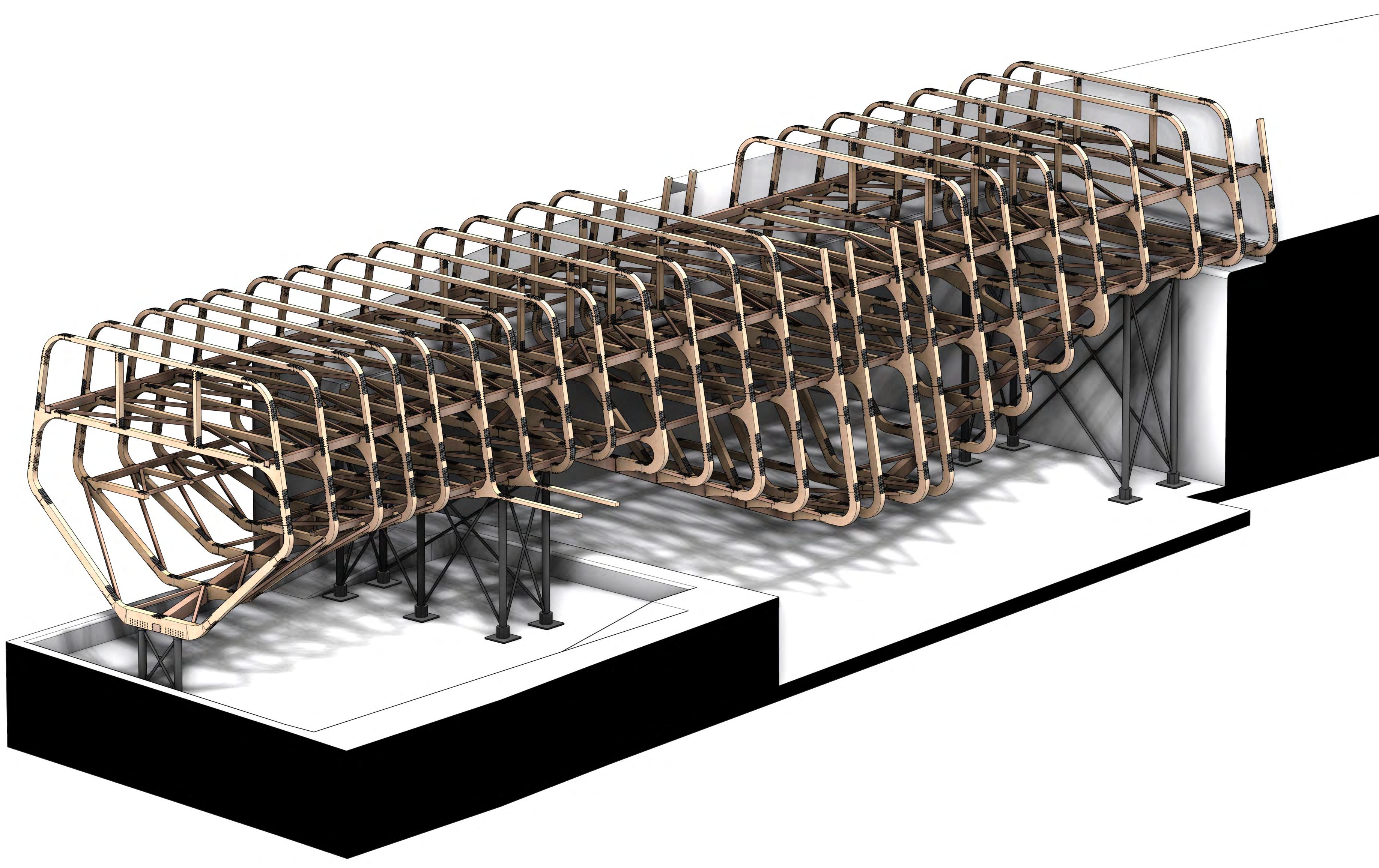
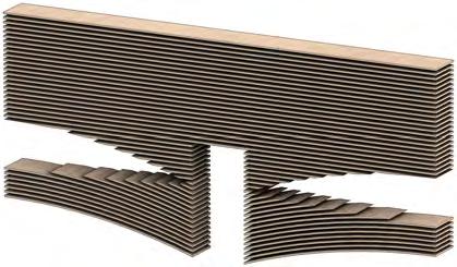
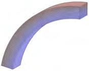
The load bearing logic of the frames is shown in the inclination of the beamsand narrowing of dimensions towards the roof. To strength further, the accoya timber is laminated to allow the wider spans that are taken, espacially in the lateral beams and components with greater curvatures.
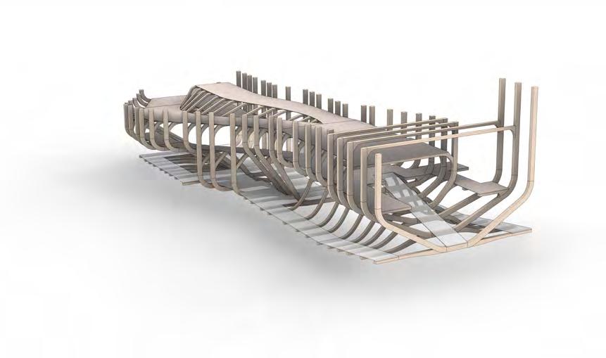
STRUCTURE Truss sysTem Timber Fr Ames LATer AL cross br Acing LATer AL beAms microP Le FoundATions + P LLArs
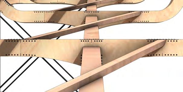
design
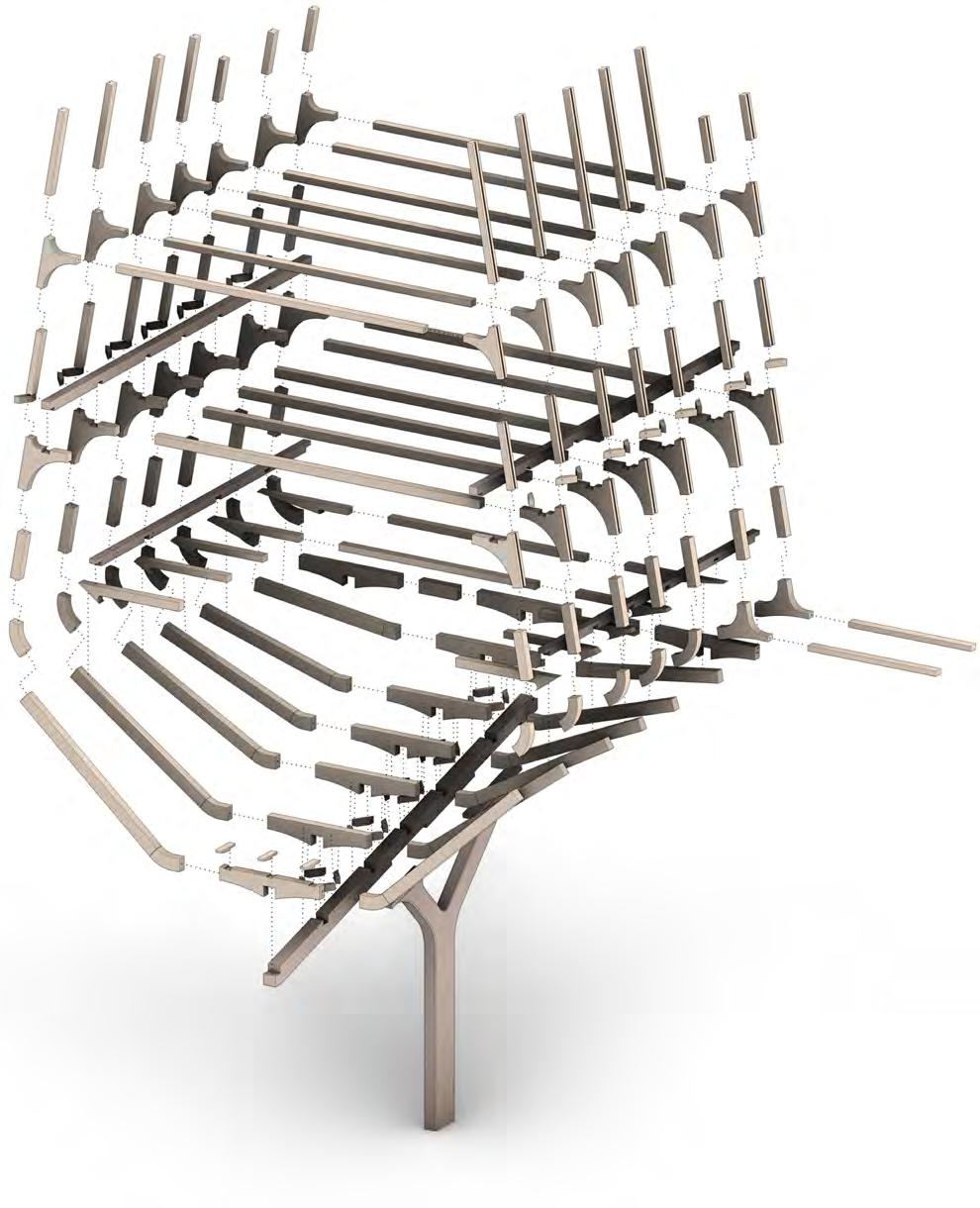
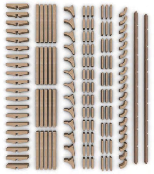
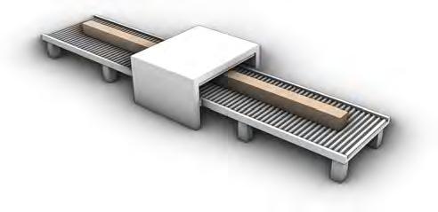
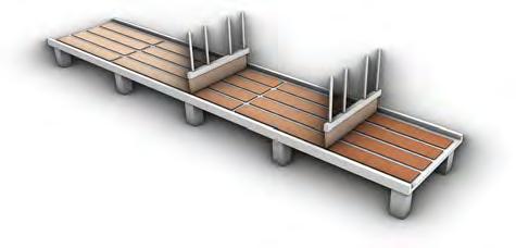
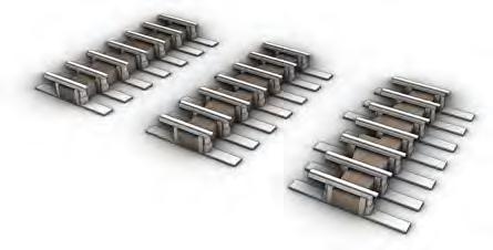
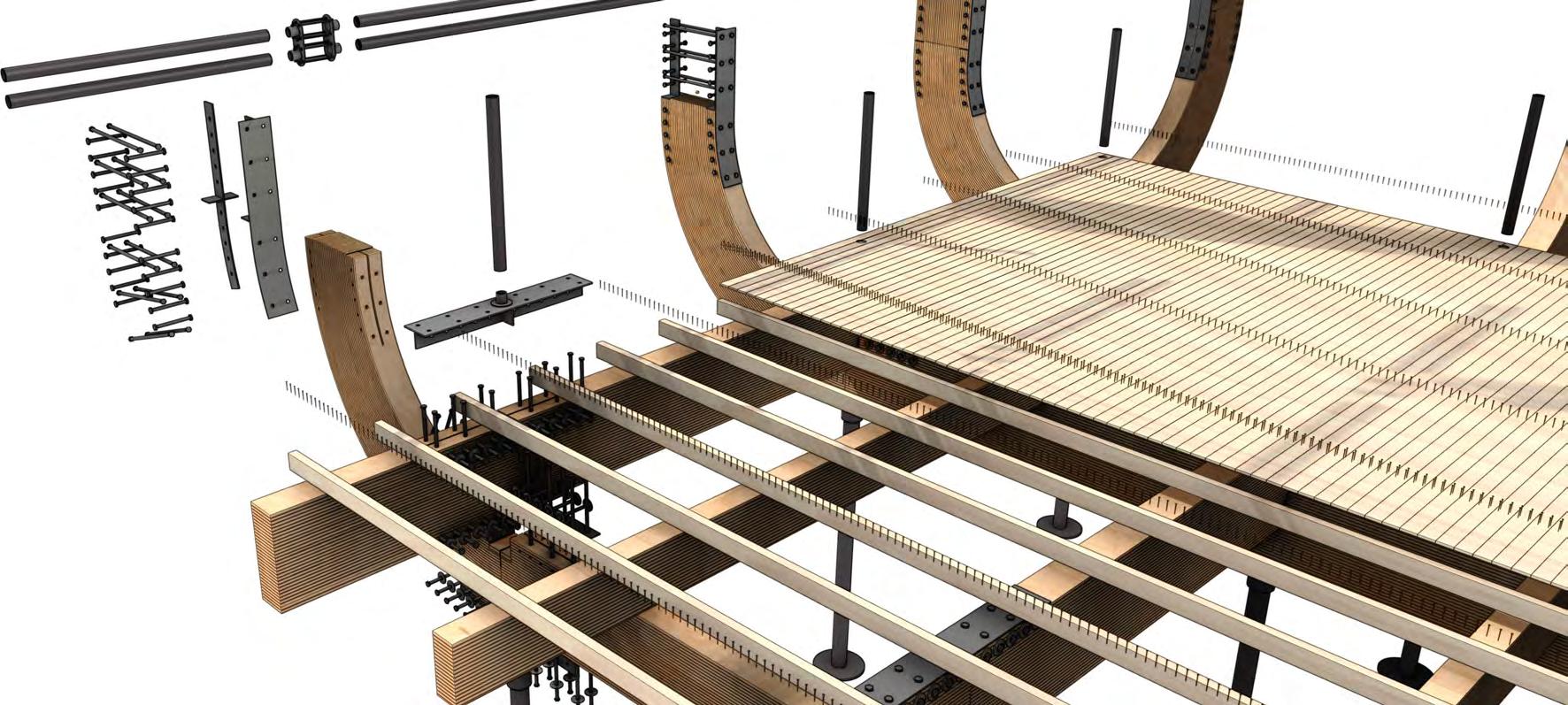
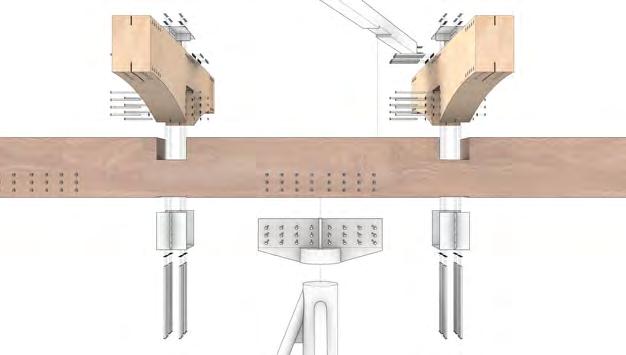
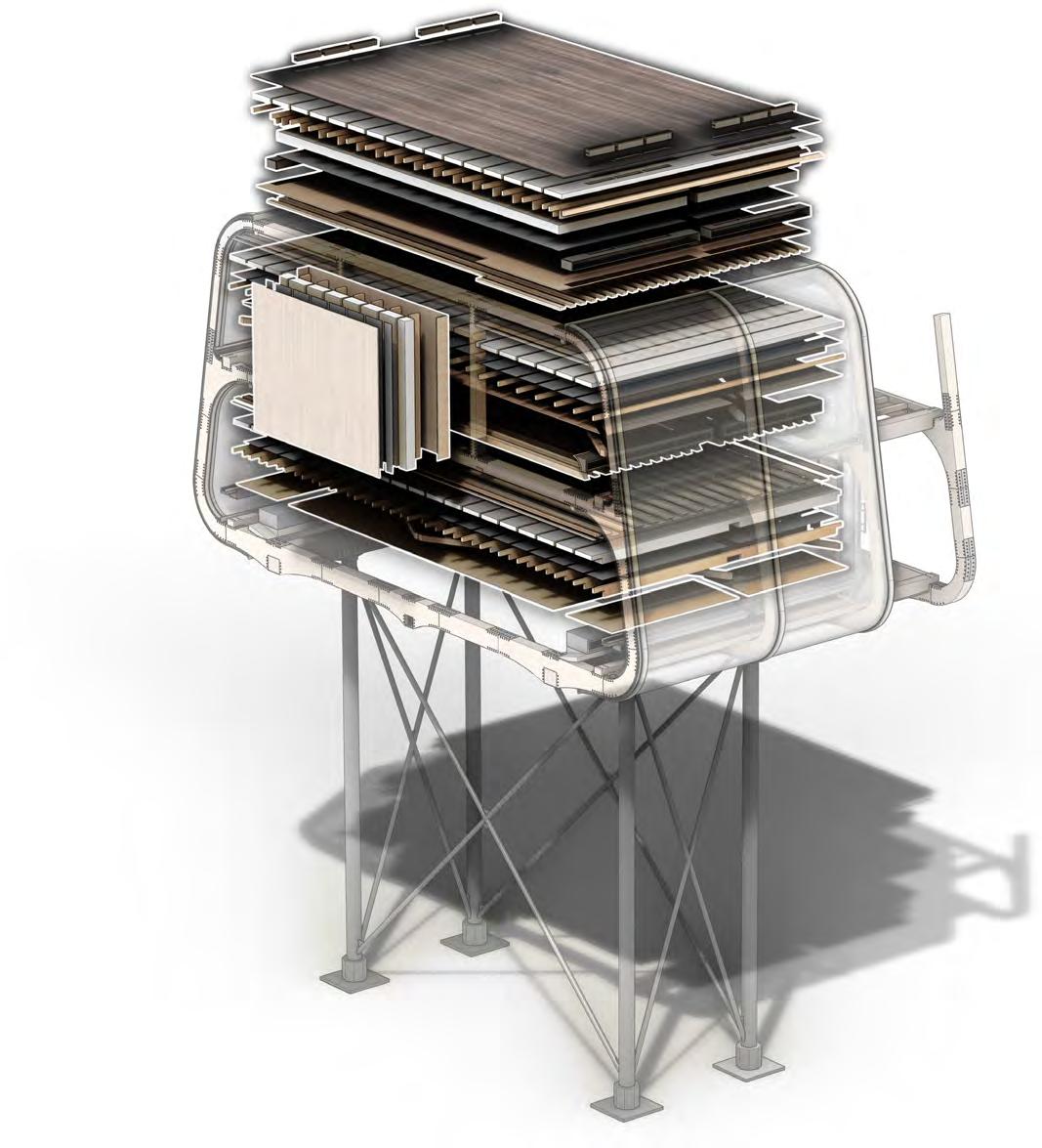
k T o PArTs
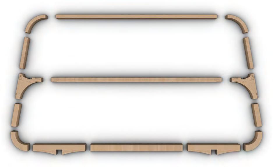
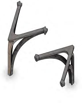
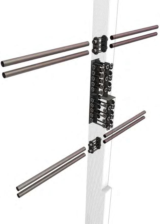
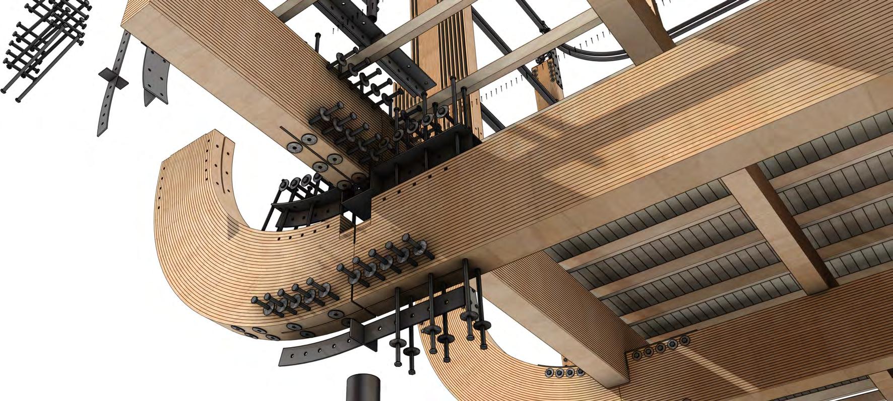
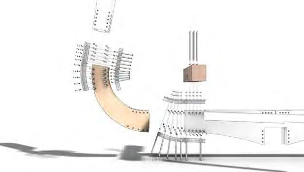
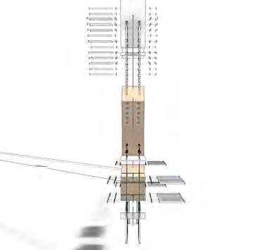
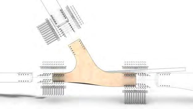
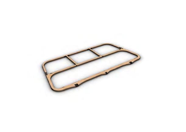
The ensure that the project achieves aspirations for efficient construction and minimised waste, the primary strucutre is broken down into individual components that are repeated frequently, enabling batch production.
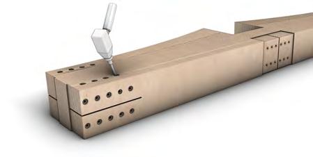
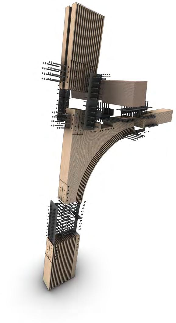
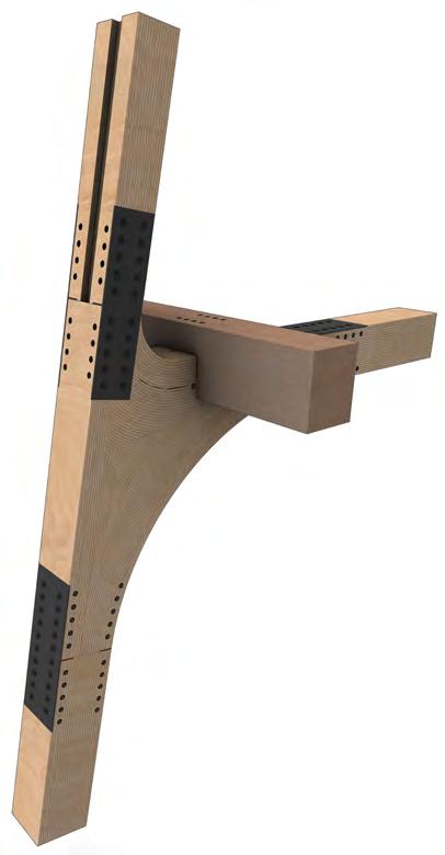
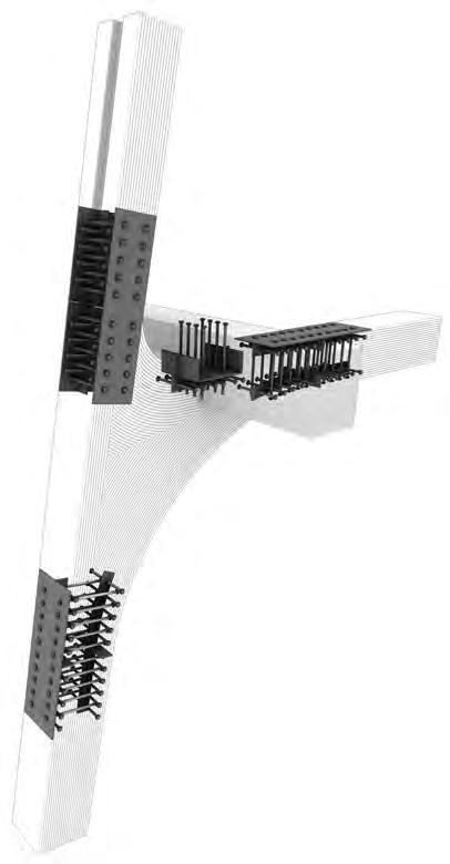
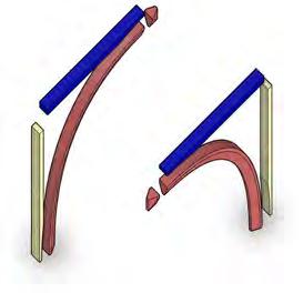
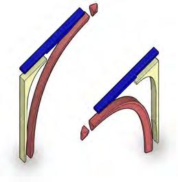
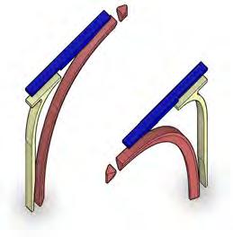
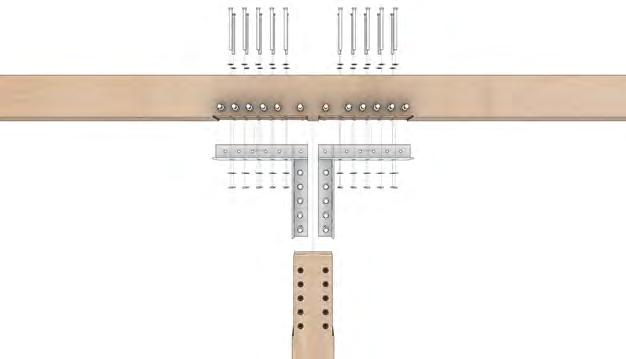
As the primary structure consists predominantly of accoya timber, these are divided into components at points where the frames are repeated and meet unique junctions. A common method of steel bolt and plate fixings allows for a single, simple method of assembly.
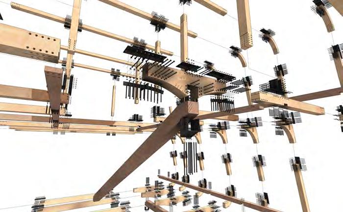
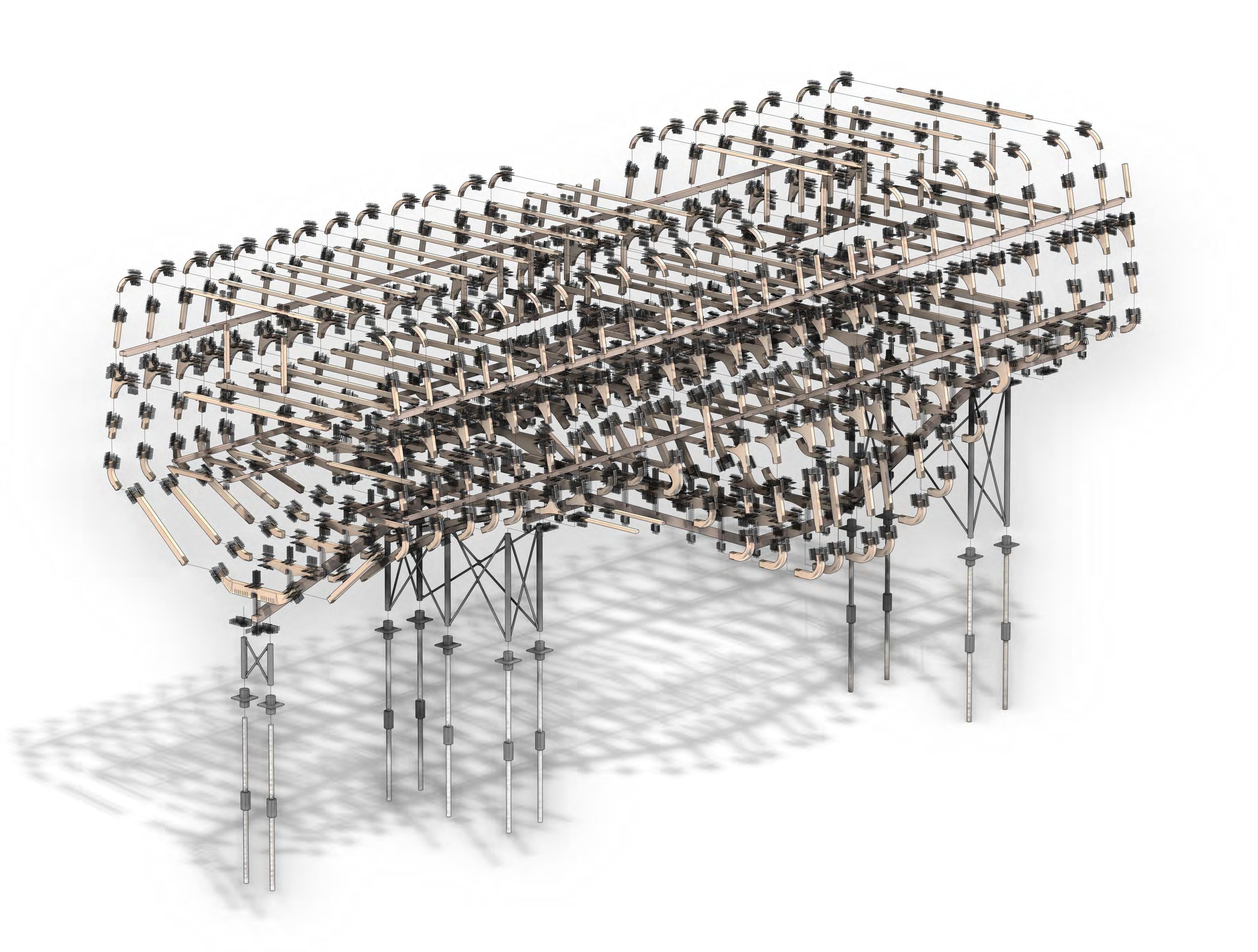
The benefits of such a system include the abililty to replace individual components as needed, as opposed to replacing entire frames. Also, in keeping with brief, ease of disassembly and relocation of the building as required.
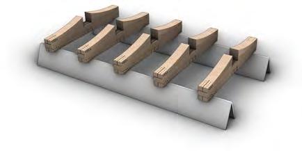
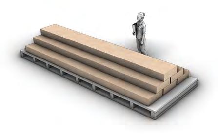
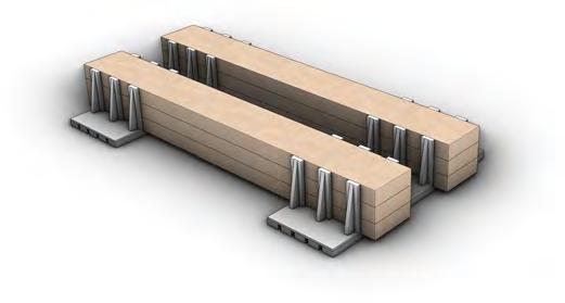
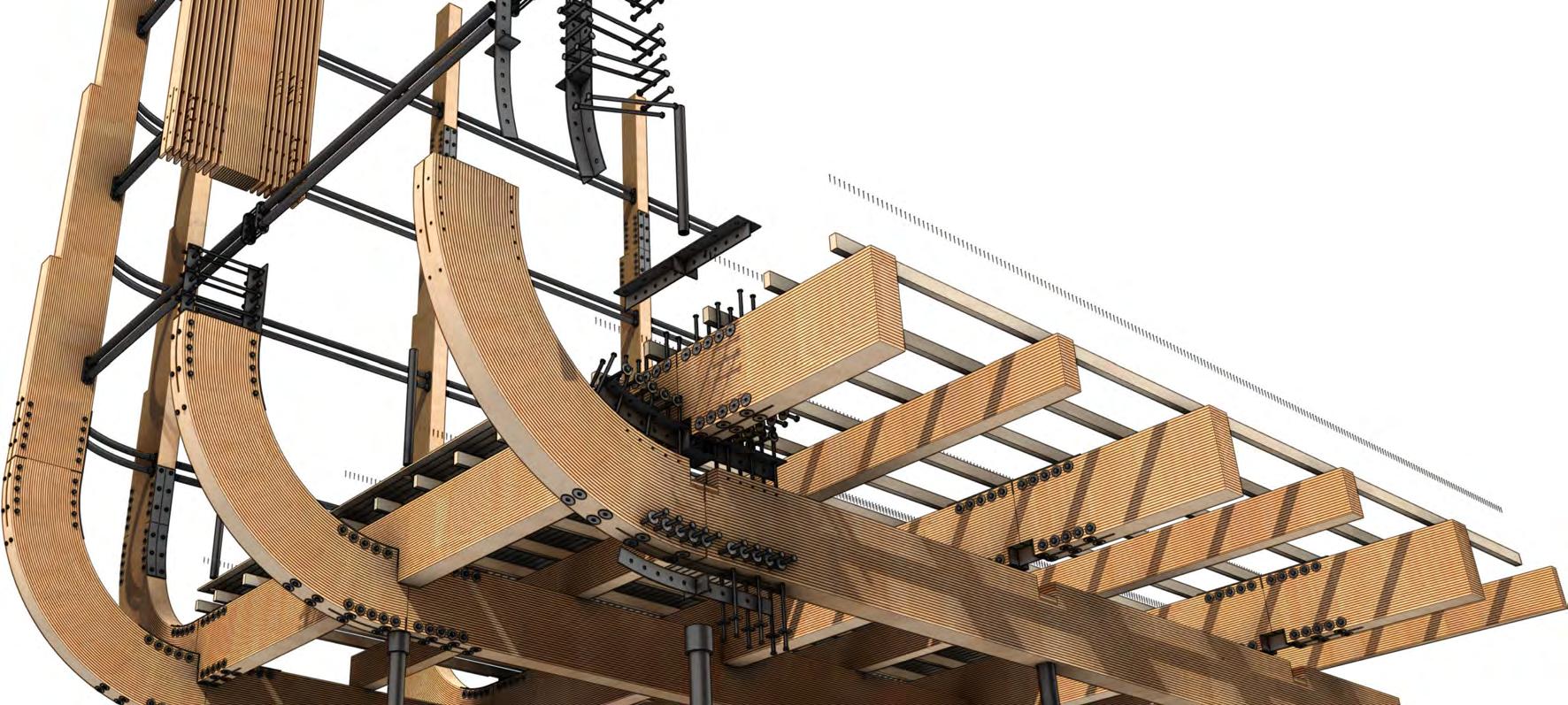
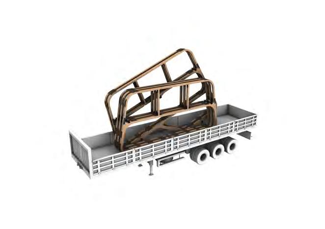
oFF s e AssembLy
To further ensure efficieny of construction and avoiding intrusive work on the archeological site, much of the structural assembly is able to be done off site and transported. The division of the structure into frames enables these frames to be assembled away from site in more controlled conditions then transported together, reducing journeys to and from site. With limited access to site due to one-way roads and a largely historic and pedestrianised location, this solution also lessens difficulties with transit and disruptions to the local community.
KIT OF PARTS
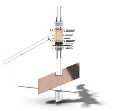
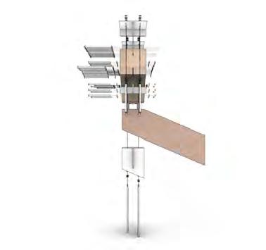
enTry sTAircAse comPonenTs
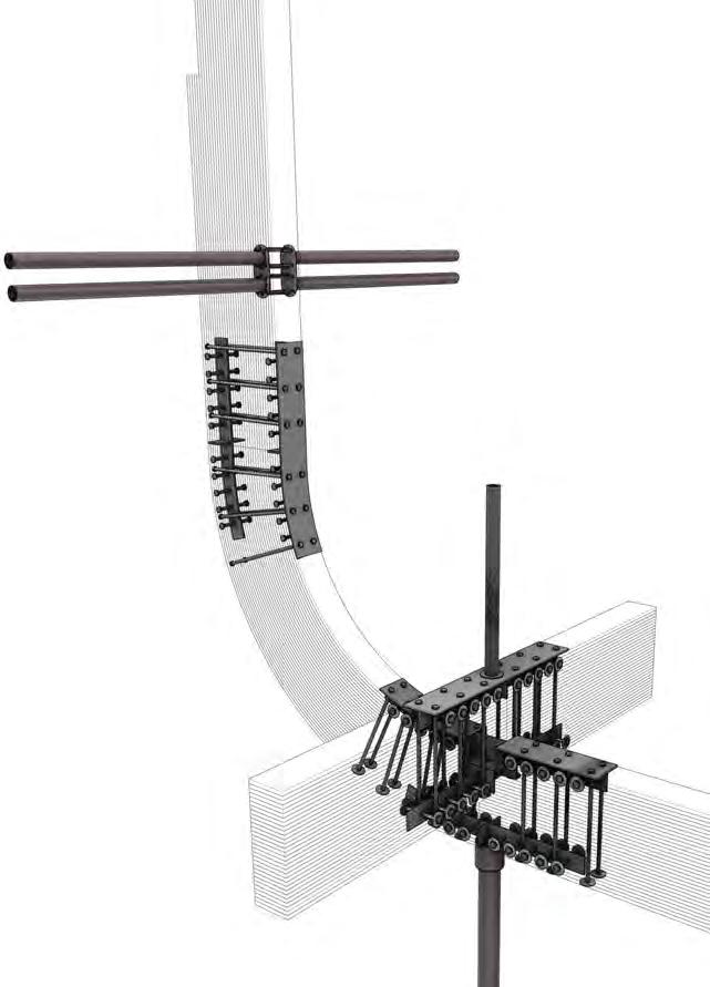
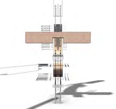
P LLAr JuncTion 1F LATer AL beAm Junc ion
sTAircAse beAm JuncTion
Timber beAms + sTeeL br AckeTs
FoundATion
2F

 1F norTh LATer AL beAm
1F souTh LATer AL beAm
2F sTAircAse beAm
1F FLoor-wALL corner
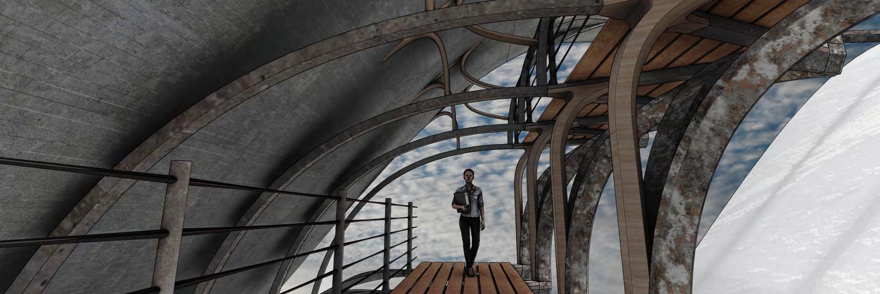
observATion PLATForm
1F norTh LATer AL beAm
1F souTh LATer AL beAm
2F sTAircAse beAm
1F FLoor-wALL corner
observATion PLATForm
KIT OF PARTS JuncTion
2F wALL-rooF JoinT
sTudies
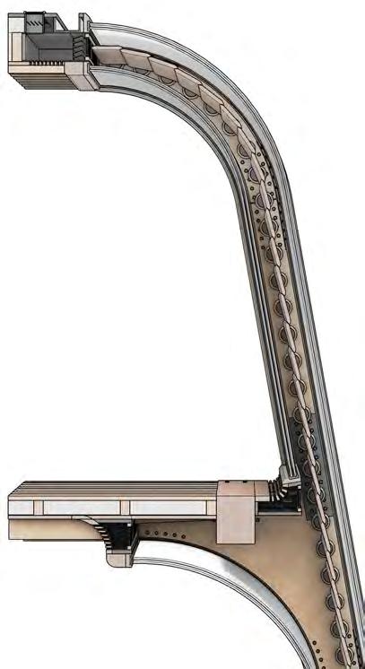
STRUCTURE TecTonic STudieS
STRUCTURE TecTonic STudieS
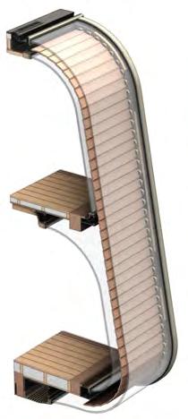
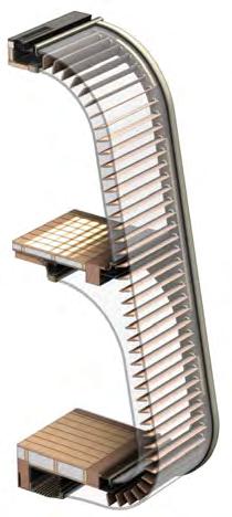
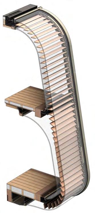
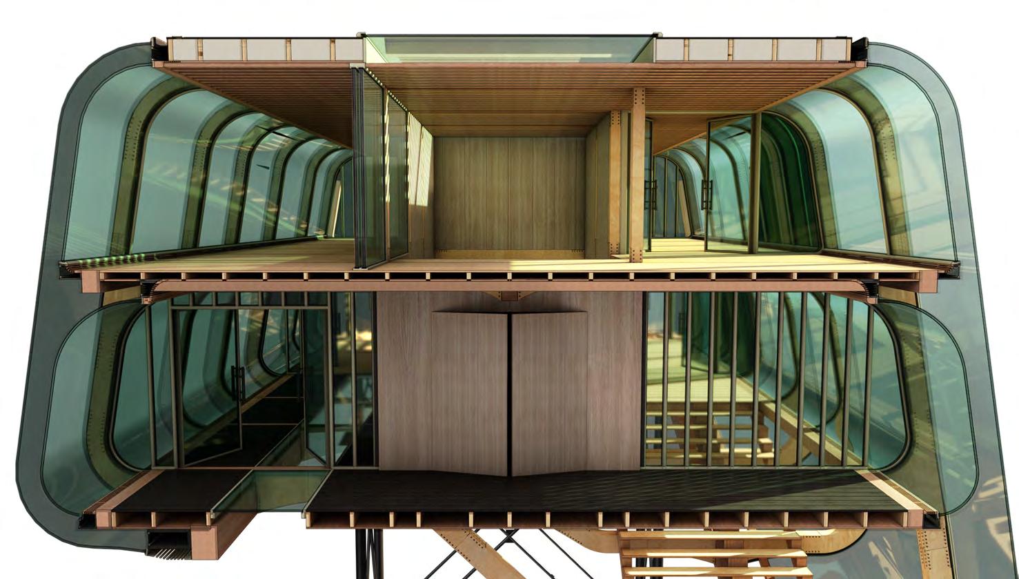
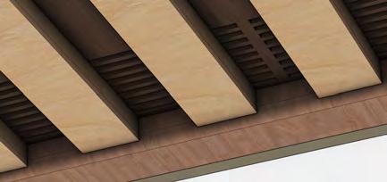
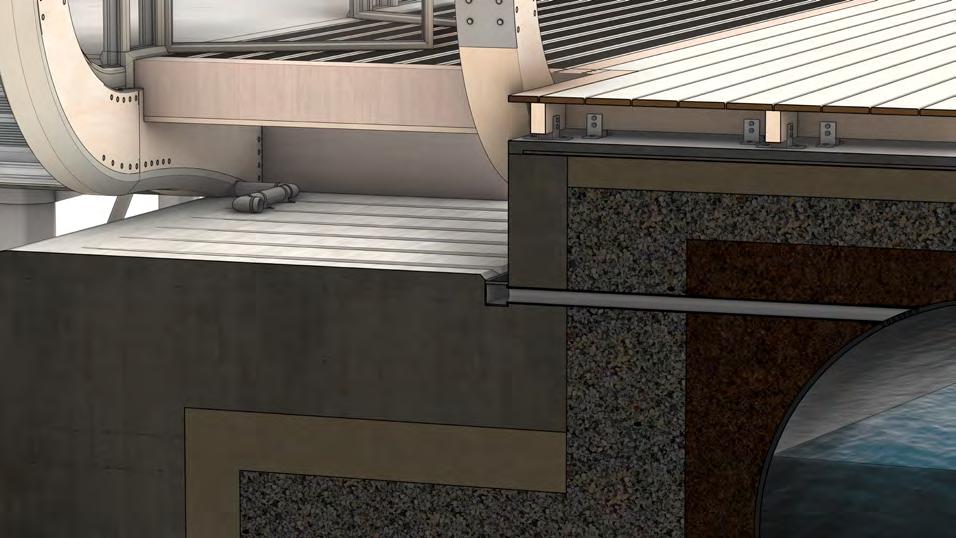
In keeping with the timber structure and character of the building design, simple timber joist and board flooring is used predominantly throughout the building. Acoustic and therma insulation is placed between the joists, with selective cavities remaining where under-floor building systems (heating, eletrical fittings etc.) are required.
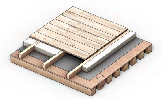
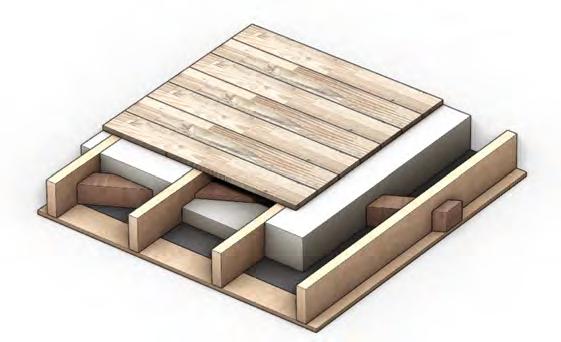
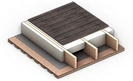
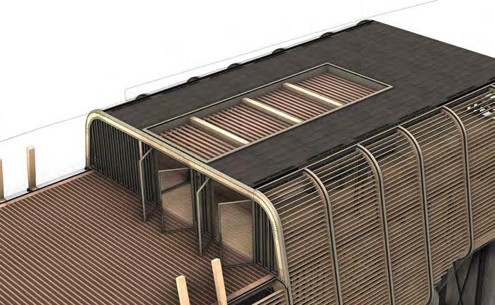
rooF + FLooring sTr ATegy
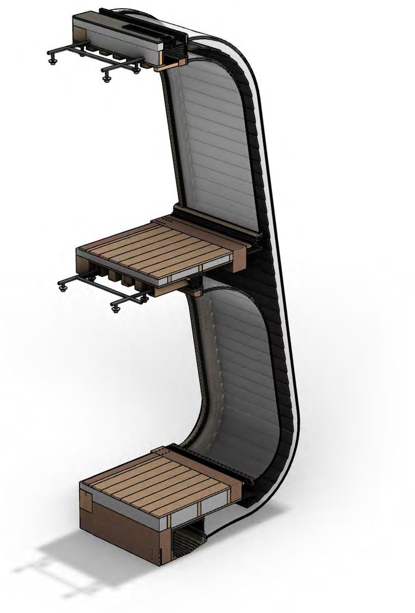
exPLoded FLoor wALL + ceiLing buiLd-uP mATeriAL LAyering 2F CEILING + ROOF 1F CEILING + 2F FLOOR 1F FLOOR 40 x 100 mm Acoustic Accoya Baffles 100 x 100 mm Accoya Beam 15 mm Sheet Pine Wood 15 mm Sheet Pine Wood 100 mm Building Systems Cavity 110 x 100 mm Acoustic Accoya Baffles PAVATEX DSB 2TM Membrane PAVATEX DSB 2TM Membrane 15 mm Sheet Pine Wood 100 mm Building Systems Cavity 100 x 100 mm Accoya Beam 50 x 230 mm Engineered Timber Joists PAVATEX DB 3.5TM Membrane 50 x 175 mm Engineered Timber Joists 100 mm Building Systems Cavity 230 mm PAVAFLEX tm Insulation 50 x 75 mm Engineered Timber Joists 175 mm PAVATHERMTM Insulation 20 mm Charred Accoya Roofing 75 mm PAVATHERMTM Insulation 150 x 20 mm Accoya Flooring 150 x 20 mm Accoya Flooring ENVELOPE rooF + FLoor ProPerTies
CloSEd louvrES
opEnEd louvrES
louvrEd doublE Skin FaCadE
Partially Enclosed Space Environmental Controlled + Solar Shading
EnvElopE StratEgy
Frame + Inner Glazing Frame Insulating + Low E Coated Glazing
Louvres
Outer Tempered + Motorised Enclosed
Outer Insulating + Solar Control Coated Glazing
Enclosed Rainwater Down Pipes
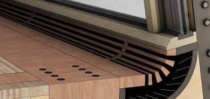
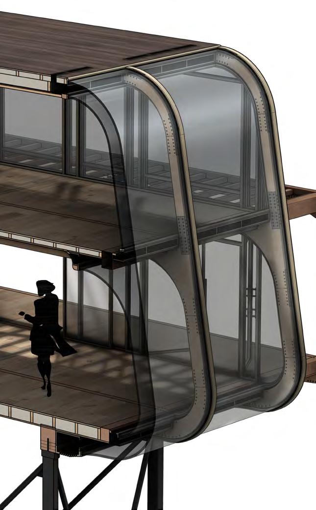
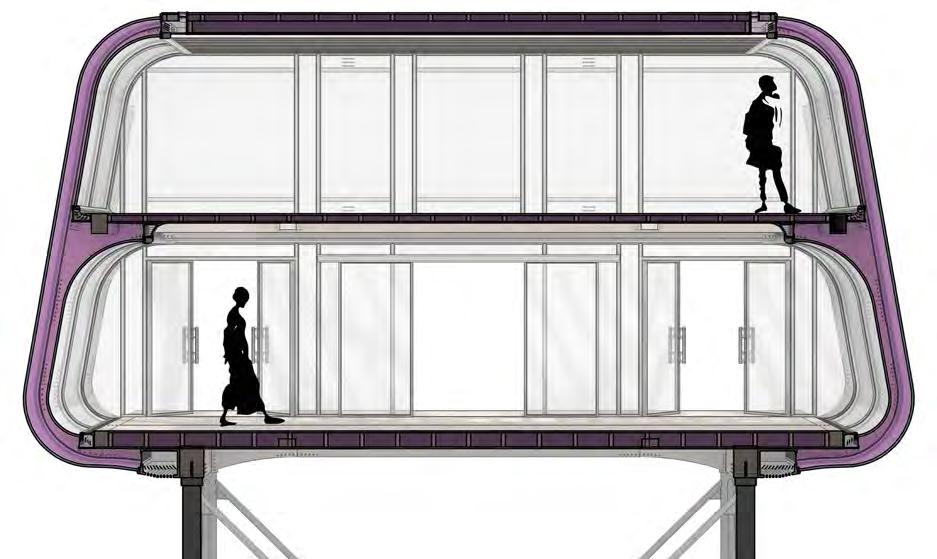
Comprising the majority of the facade along the long sides of the building is a double skin system that sandwiches motorised louvres in a cavity between two layers of glazing. The double skin acts to create a transparent yet environmentally controlled internal space, while the louvres further modify this transparency and control as required. Laminated Glazing
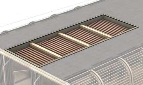
Fully Enclosed Space Environmental Controlled Photovoltic Power Generating Skylight
ENVELOPE EnvElopE SyStEm
Diagram Key Unenclosed Space Fragment
Air FLow AcousTic ThermAL
gLA zed doubLe skin FAcAde
Layering of two glass walls - positioned on the inner and outer faces of the structure - to provide an intermediate cavity of free flowing air. This provides superior thermal efficiency at both high and low temperatures, while still enabling a transparent quality for views and natural lighting.

environmenTAL conTroL
moTorised roTATion
encLosed moTorised Louvres
In the cavity of the double skin facade are motorised louvres that can be adjusted automaticall and manually as desired. They will allow for further environmental control in increasing ventilation airflow when shut - useful also for security in obscuring external views at night - or allowing views out and sunlight to permeate when opened.
Louvred doubLe skin FAcAde
-3.0
0.0 -3.0
ENVELOPE
0.0
0.0

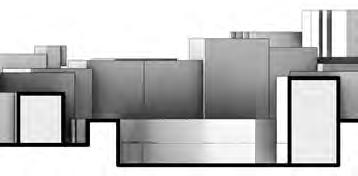
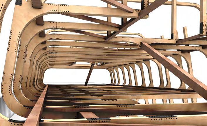
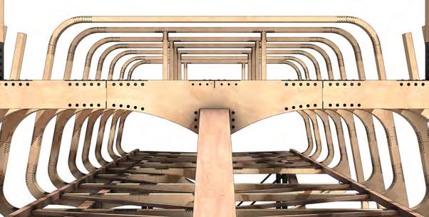
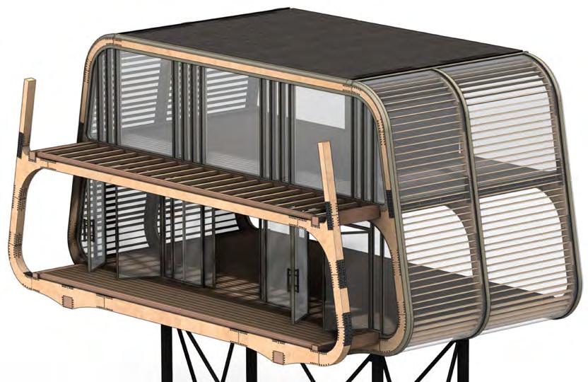
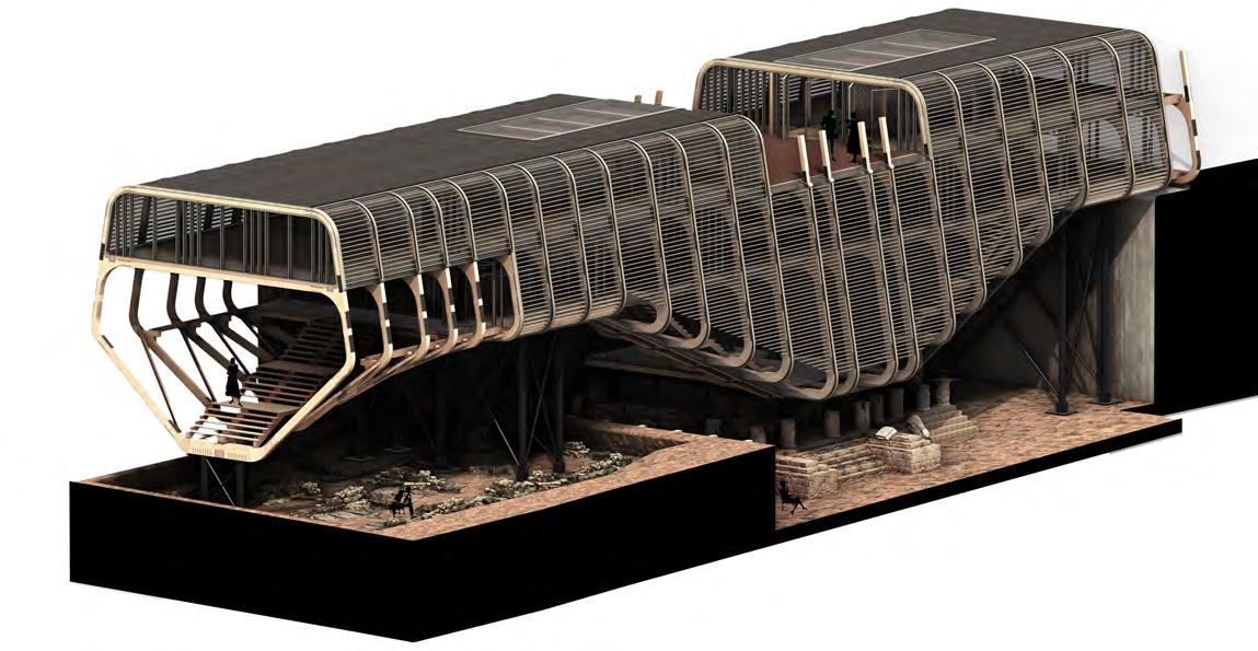
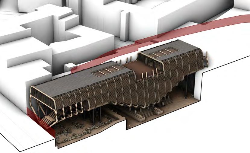
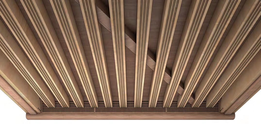
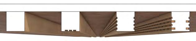
BUILDING FORM EnvElopE ovErall
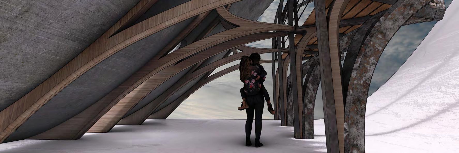
BUILDING FORM UndErsidE Conditions

17 1 2 3 4 5 13 6 h n c e b a d g k m p o Medieval Farmhouse Retaining Wall + Ramp Descent l0 - ExCavation dig sitEs Roman Temple Roman Mausoleum Excavation Overlook 1 2 3 4 5 Lecture Theatre Study Room + Library l2 - aChEology dEpartmEnt Lobby Threshold Roof Terrace Artefact Examination + Cataloguing 14 15 16 17 18 Trinity Street Entrance + Lobby East Campus Staircase l1 - Exhibition Excavation Artefacts Exhibition West Campus Staircase Artefact Storage Trinity College Campus Entrance + Lobby Trinity Street Staircase Archeology Gardens 6 8 9 11 10 12 7 13 spatial programmE 7 6 14 15 16 17 18 1 2 3 4 5 8 9 10 10 12 11 13 v w u u s r q x Floors + CEilings + Walls EnvElopE + FaCadE Retaining Timber Wall 350mm + backfill Micropile Foundation Footing 400 x 400mm Steel Pillar 240mm dia Steel Bracing Posts 80mm dia Concrete Foundation Slab 800mm + backfill Concrete Retaining Wall 500mm + backfill sitE + FoUndations h k m Primary Lateral Beam 400 x 300mm End Base Junction 300 x 480mm Accoya Frame 150 x 200mm to 300 x 200mm primary strUCtUrE Steel Bolt Plate Fixings Lateral Bracing 100 x 100mm Secondary Lateral Beam 175 x 200mm Suspended Steel Cable 30mm dia a b c d e g strUCtUral ComponEnts Double Skin Glazed Facade + Louvres 300 to 400mm Roof + 2F Ceiling + Acoustic Baffles 300mm Charred Accoya Roof Panels 25mm 2F Flooring + 1F Ceiling + Baffles 305mm Low-E Insulating Rooflight 60 x 8480 x 3280mm 1F Flooring 220mm Double Skin Glazed Facade 200mm Multi-laminated Glass Floor 100mm Retaining Timber Wall 350mm Charred Accoya Flooring 20mm Partially Charred Accoya Decking 25mm Accoya Decking 25mm n o s p q u v w x y BUILDING DESIGN bUilding ovErviEW
DESIGN REFINEMENT
DETAIL, ENVIRONMENTAL + FORM RESOLUTION
Structure GeneSiS
STRUCTURE
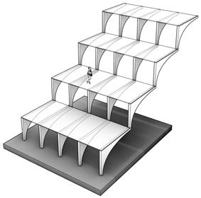
 1. Frame maSSinG + SpacinG
2. FoundationS + LandinG pointS
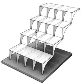
3. truSS Structure reinForcement
4. Frame Form reFinement + FittinGS
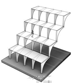
5. enveLope SupportinG Structure
Simple massing expressing the structure’s basic overall and rib frame forms, along with determining spanning widths between ribs.
Locating suitable landing points for the micropile foundations and steel pillars, with regards to archeological sensitivity.
Strengthening the frames into a truss-type structure, with addition of lateral supports, cross bracing and other load bearing features.
Refining the structural form of the individual frames, reducing unneccessary thickness of material and better dispersing loads.
Addition of sub-structural elements to the primary structure, such as joists, stair beams and facade frames, to support the envelope.
1. Frame maSSinG + SpacinG
2. FoundationS + LandinG pointS
3. truSS Structure reinForcement
4. Frame Form reFinement + FittinGS
5. enveLope SupportinG Structure
Simple massing expressing the structure’s basic overall and rib frame forms, along with determining spanning widths between ribs.
Locating suitable landing points for the micropile foundations and steel pillars, with regards to archeological sensitivity.
Strengthening the frames into a truss-type structure, with addition of lateral supports, cross bracing and other load bearing features.
Refining the structural form of the individual frames, reducing unneccessary thickness of material and better dispersing loads.
Addition of sub-structural elements to the primary structure, such as joists, stair beams and facade frames, to support the envelope.
0.
Primary structural frames are assembled in a controlled environment off-site so as to minimise disturbance to site. They are then transported to site at a time when they are able to be put into place with little disruption.

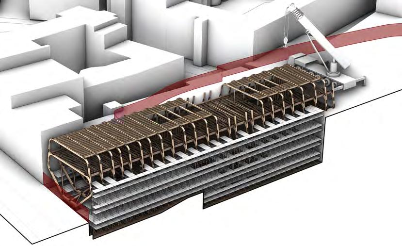
STRUCTURE conStruction phaSinG
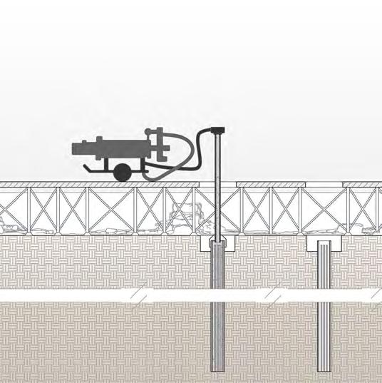
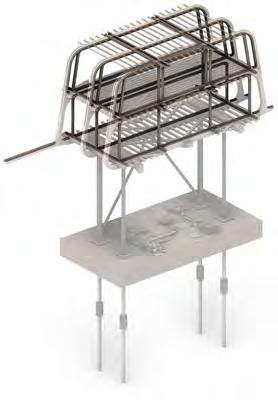
1. micopiLe FoundationS While off-site preparations are being made, initial scaffolding is put in place to support the introduction of micropile foundations into the site, taking into account archeological constraints in enabling micropile rigs and drills to navigate the site.
2. ScaFFoLdinG Building of the temporary supporting structure before the frames are delivered. Using site sensitive footings and placements to avoid disruption of the ruins, while still coving a suitable footprint to enable on-site construction.
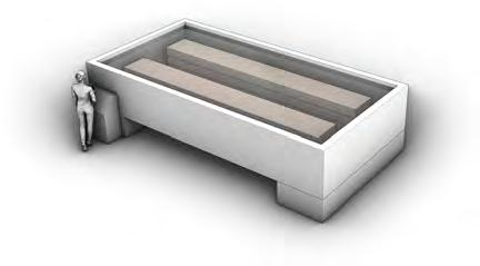
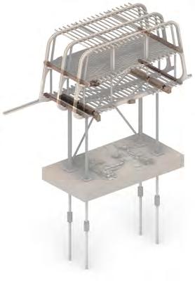
3. primary Structure Craning into place the primary structure that has been built off-site, including the accoya frames and lateral beams that comprise the truss structure; starting with the base lateral beam fixed to the foundation pillars before placing the frames.
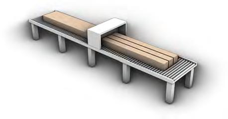
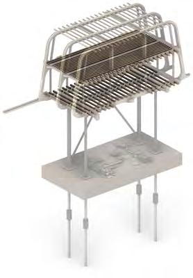
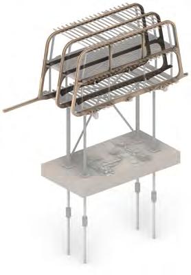
4. Secondary Structure Assembly of the secondary lateral beams, cross bracing beams and floor and roof joists. Providing the initial structure with greater integrity so it becomes less dependant on the scaffolding for support.
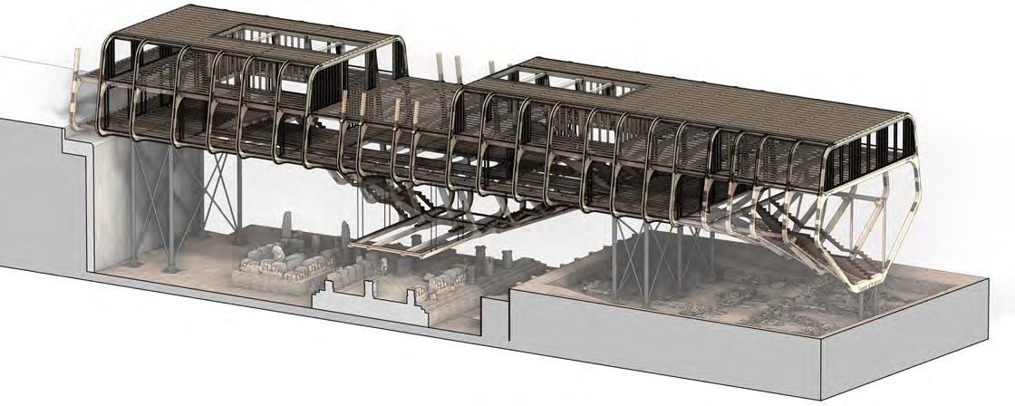
5. enveLope Addition of the building’s envelope layers, such as the roof, floors and exterior glazing walls. These being assembled to the base structure and providing internal levelled spaces that negate the further need for scaffolding and craning.
6. interiorS With the scaffolding now fully removed, work on the interior fit out continues, starting at the lower levels so they can be opened sooner to accommodate the public and archeological dig programme aspects.
oFF-Site contruction
The building’s environmental conditioning systems are held most significantly within the double skin glazed facade. This envelope is comprised of internal and external glass layers with an air cavity between that allows passive airflow and controlled environment regulation. The addition of motorised louvres also held in this cavity support this system in both airflow and solar shading control.

While daylighting is significantly increased with these fully glazed facades, their primary purpose is to create a more visually transparent impression, bringing focus to looking through the building and thus at the ruins in shelters. With some walk on glass flooring this intention is furthered, however, due to the sensitivity of the artefacts examined and displayed, greater consideration is prioritised to the thermal barriers between floors and spaces.
interGrated environmentaL deSiGn
BUILDING SYSTEMS
Facade ventiLation
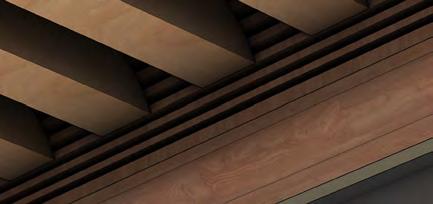
dayL GhtinG - Louvred GLazinG thermaL - doubLe Skin enveLope acouStic extenSive timber baFFLeS airFLow - paSSive
environmenta StrateGy
8 8 10 9 1 2 3 4 6 7 5 11 enveLope + Facade Double Skin Glazed Facade + Louvres 300 to 400mm Charred Accoya Roof Panels 25mm Low-E Insulating Rooflight 60 x 8480 x 3280mm Double Skin Glazed Facade 200mm 8 9 10 11 FLoorS + ceiLinGS + waLLS Roof + 2F Ceiling + Acoustic Baffles 300mm 2F Flooring + 1F Ceiling + Baffles 305mm 1F Flooring 220mm Multi-laminated Glass Floor 100mm Retaining Timber Wall 350mm Charred Accoya Flooring 20mm Partially Charred Accoya Decking 25mm 1 2 3 4 5 6 7
Glass
Uses:
Uses:
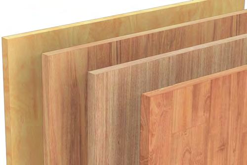
- Primary structure
- Flooring
- Roofing
- Acoustic baffles
- Envelope louvres
Finishes:
- Uncoated
- Oil finished
- Charred / Shou Sugi Ban
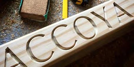
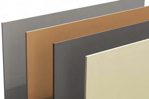
accoya tiMber aluMiniuM
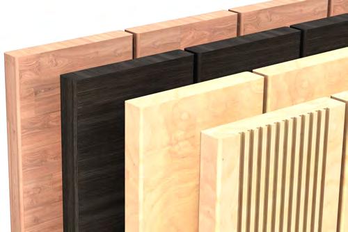
Uses:
- Window/Door frames

- Handrailing
- Vent covers
- Detailing
Finishes:
- Champagne metal varnish
- Wood effect
- Raw
Material Pallet
MATERIAL
- Walk on glazed floors
- Double skin facade
- Skylights
- Internal walls
Types:
- Tempered + laminated
- Solar control coating
- Photovoltic power generation
- Insulating + low E coating
Pine Wood
Uses:
- Ceiling panels
- Wall panels
- Floor joists
- Secondary structure
Finishes: - Wood preserative
- Oil finished
- Varnished
StructuraL componentS repLacement
The primary truss structure has a lifepan of 80 years for the accoya components and 60 years for the steel brackets. However, if any critical damage occurs, those components affected can be removed and replaced without the entire structure being faulted.
buiLdinG StrateGieS
BUILDING SYSTEMS
environmentaL StrateGieS 12am 61.9 E W 9am 45.3 Thermal Line Summer Solstice Sun Ray Fresh Air Warm Air Rainwater Path Air Source Underfloor Heating Charred Accoya Louvres 90 years Primary Accoya Structure 80 years Pinewood Joists 40 years Accoya Floor Boards 30 years Insulation 100 years Primary Accoya Lateral Beam 80 years Insulating + Low E Coated Glazing 40 years Outer Tempered + Laminated Glazing 40 years Aluminium Clad Frames 45 years Ventilation System 20 years Charred Accoya Roof Panels 70 years Fire Suppression System 20 years Accoya Accoustic Baffles 80 years Secondary Accoya Lateral Beam 80 years Insluating + Solar Control Coated Glazing 30 years Steel Bracket + Bolt Joints 60 years
kit
oF partS LiFeSpanS
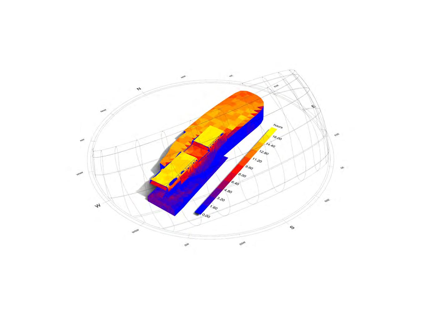
The proposal runs East to West in an urban environment, with relatively clear space to the North but a close neighbouring building to the South. Although this building will likely overshadow the proposal at the lower levels, this is not a negating factor as the programme held here requires more controlled lighting and daylight exposure.
BUILDING SYSTEMS
liGhtinG l GhtinG Plans 2f Plan 1f Plan Recessed Spotlight Rail Lighting System Floor Edge Lighting Enclosed Dispay Natural Light 500 lx 500 lx 200 lx 200 lx 500 lx 200 lx 200 lx 100 lx 300 lx 300 lx 300 lx 100 lx 100 lx hourly sunliGht 12 22 10 20 8 18 16 14 WINTER SOLSTICE: 22/12/2023 12 22 10 20 8 18 16 14 SPRING EQUINOX: 20/03/2023 12 22 10 20 8 18 16 14 SUMMER SOLSTICE: 21/06/2023 l GhtinG
dayliGht + artificial
strateGy
direct sunliGht analysis staicase atriuM roof 1:5 Clear Soft Coat Inner Pane 10mm Accoya Acoustic Baffle 100x40mm Argon Filled Cavity 17mm Photovoltic Generating Glass 20mm Steel Bracket 5mm Skylight Frame Fittings (allowing removal of glass) Coated Aluminium Sheet 5mm PVDF Coated Steel Sheet 3mm
suMMer solstice: 9aM 45.3o Winter solstice: 9aM 5.5o sPrinG equinox: 9aM 24.9o BUILDING SYSTEMS dayliGht studies
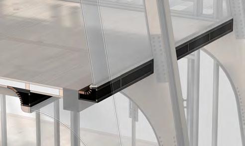
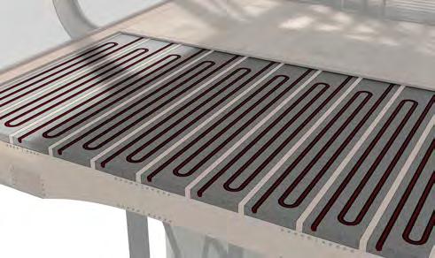
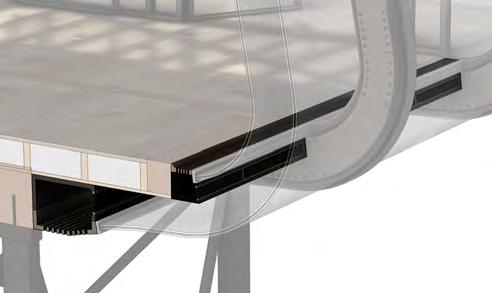
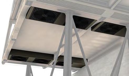
BUILDING SYSTEMS airFLow + thermaL interGrated vent deS Gn thermaL + airFLor SyStemS intake + 1F FLoor air Source unit 1F ceiLinG + 2F FLoor underFLoor heatinG 2F ceiLinG + rooF outLet photovoLtic enerGy GeneratinG GLaSS 1F VENTILATION INTAKE + GLAZING JUNCTION 1:10 Toughened/Laminated Glass 30mm Accoya Facade Louvres 20x110mm Accoya Lateral Beam 250x200mm External Intake Vent Steel Cable Suspension 1F Floor Vent thermaL With the private educational and public exhibition spaces requiring greater environmental control, they are prioritied in thermal insulating considerations. The entryways are act as thermal thresholds, being partially insulated, and the excavation overlook space being fully enclosed. Controlled air flow Wind Full thermal enclosure Partial thermal enclosure Unenclosed Under floor heating LectureTheature StudyRoom Artefact Examination RoofTerrace Campus Entrance Street Entrance Public Exhibition ExcavationOverlook
The elevated and recessed street facing entrance acts to reduce noise pollution from the busy public street, while thresholds here and at the rear act to interrupt the passage of sound. More accoustic treatment is then also given to the 2F private educational and research spaces.


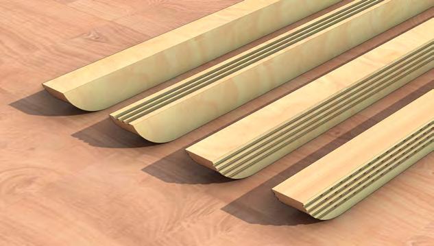
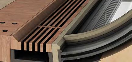
accoya baFFLe optionS typicaL 1F ceiLinG acouStic ceiLinG baFFLeS FraGment acouStic Study north-South Section eaSt-weSt Section acouSticS
Acoustic barrier Unenclosed Partially sealed Fully acoustically sealed Noise source LectureTheature StudyRoom Artefact Examination RoofTerrace Campus Entrance StreetEntrance Public Exhibition ExcavationOverlook BUILDING SYSTEMS acouSticS
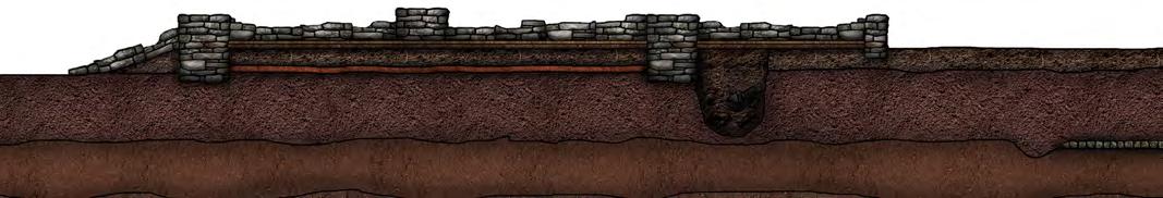
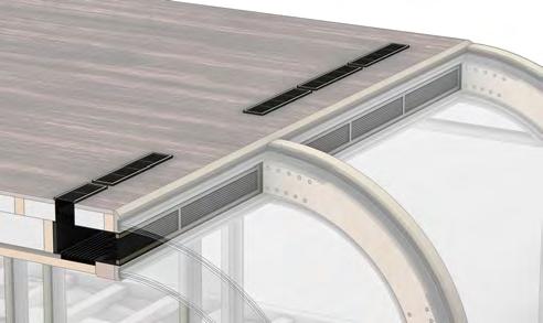
Rainwater accumulated on the roof of the building will disperse to guttering on running along the edges of the long sides, due to a slight gradient on the flat surfaces. This travels along rainwater pipes enclosed in the glass envelope frames to another pipe that will carry the water to the end frames, and then again down to ground level. Here it is stored in an underground retention tank, to be dispersed in maintaining the site’s biodiversity.
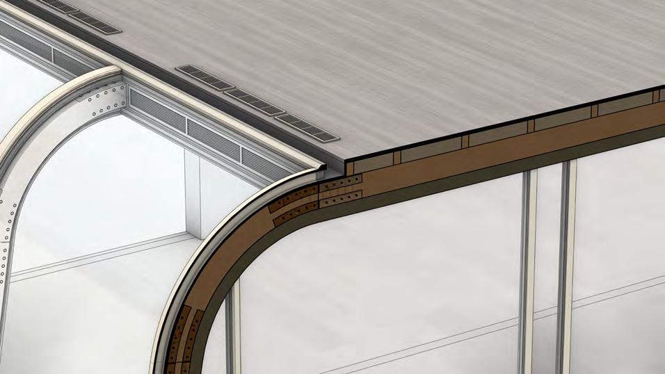
rainwater manaGement
rooF rainwater intake water hoLdinG tank coLLection Surface run-off key External guttering Internal rainwater pipe Drip control edge Irrigation dispersal Facade drip edGe 1:2 27x20mm Aluminium Drip Bar EPDM Rubber Seal Laminated Low E Glass rooF terrace GutterinG 1:5 3mm Aluminium 5mm PVC Gutter Laminated Low E Glass 250x200mm Accoya Lateral Beam 95x75mm Timber Beam interaL rainwater pipe 1:5 22mm Timber Beam 3mm Aluminium 3mm Aluminium 5mm PVC Gutter Laminated Low E Glass Steel Guttering Grate 10mm Timber Board BUILDING SYSTEMS rainwater coLLection
ENVELOPE EnvElopE StudiES

ENVELOPE EnvElopE StudiES
ENVELOPE EnvElopE StudiES
ORTHOGRAPHIC 0F + 1F PLAns N 10m 5m 0 2m 1m 1:200 Key Trinity Street staircase Archeological dig workstations West excavation staircase Medieval Farmhouse excavation Roman Temple excavation East excavation staircase Double skin glass facade Micropile foundations + pillars Roman Mausoleum excavation Timber retaining wall Concrete retaining wall Timber retaining wall + excavation ramp Glass platform overlook 1 6 11 2 7 12 13 3 8 4 9 5 10 10 7 3 AA BB BB AA 3 2 4 1 TRINITY STREET WINSTANLEY LECTURE THEATRE TRINITY COLLEGE 19-20 TRINITY STREET 18 TRINITY STREET 6 5 9 13 11 12 8 Trinity Street staircase West exhibition corridor East campus staircase + turntyles Trinity Street entrance + lobby Excavation artefacts exhibition Campus side entrance + lobby External decking Archeological garden Key West campus staircase + turntyles East exhibition corridor West excavation staircase Artefact storage General storage East excavation staircase 1 6 11 2 7 12 13 14 3 8 4 9 5 10 AA BB BB AA 1 3 5 4 2 6 8 7 12 13 14 10 9 11 TRINITY STREET WINSTANLEY LECTURE THEATRE TRINITY COLLEGE 19-20 TRINITY STREET 18 TRINITY STREET L0 Plan L1 Plan
ORTHOGRAPHIC 2F + rooF PLAns N 10m 5m 0 2m 1m 1:200 Archeology lecture theatre East terrace lobby threshold Study room + library East campus staircase Key West campus staircase Artefact examination + cataloguing West terrace lobby threshold External roof terrace 1 6 2 7 3 8 4 5 AA BB BB AA 1 2 4 6 5 3 7 8 TRINITY STREET WINSTANLEY LECTURE THEATRE TRINITY COLLEGE 19-20 TRINITY STREET 18 TRINITY STREET L2 Plan L1 Plan Charred accoya roof Glass skylights Key External roof terrace Double skin glazed facade 1 2 3 4 AA BB BB AA 2 2 3 4 4 1 1 TRINITY STREET WINSTANLEY LECTURE THEATRE TRINITY COLLEGE 19-20 TRINITY STREET 18 TRINITY STREET
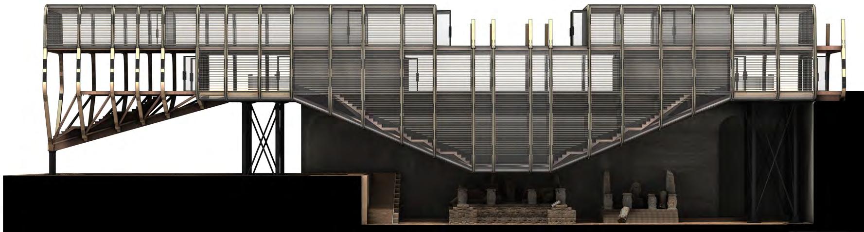
ORTHOGRAPHIC
10m 5m 0 2m 1m 1:200 Trinity Street staircase Archeological dig workstations Archeology lecture theatre Conrcete slab foundations Archeological garden Glass skylights West campus staircase + turntyles Medieval Farmhouse excavation Roman Temple excavation Study room + library Trinity Street entrance + lobby West terrace lobby threshold General storage East terrace lobby threshold External roof terrace Excavation artefacts exhibition Artefact storage Artefact examination + cataloguing Key Micropile foundations + pillars Roman Mausoleum excavation Timber retaining wall Concrete retaining wall East campus staircase Timber retaining wall + excavation ramp Glass platform overlook Campus side entrance + lobby 1 6 20 11 19 22 13 2 7 21 12 23 14 25 24 15 16 26 3 8 4 9 17 5 10 18 BB BB 7 10 8 3 9 11 26 19 18 17 22 22 24 15 12 13 1 2 3 4 5 6 16 14 21 20 25 23 Section AA External roof terrace Roman Temple excavation Excavation artefacts exhibition Micropile foundations + pillars Key Double skin glass facade + louvres Concrete retaining wall East excavation staircase Glass platform overlook 1 6 2 7 3 8 4 5 8 7 AA AA 6 5 3 3 4 2 1 Section AA
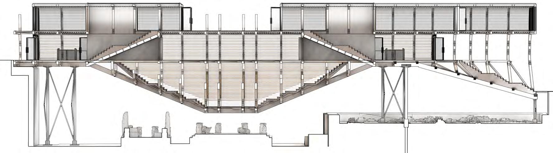
secTions AA + bb
FINAL DRAWINGS
CONCLUDING DESIGN VISUALS
FINAL DRAWINGS SitE
DRAWINGS itE
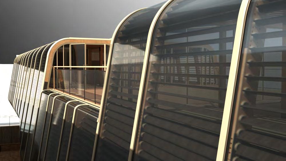
FINAL DRAWINGS StrEEtfront
DRAWINGS trEEtfront
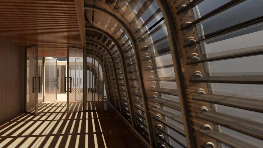
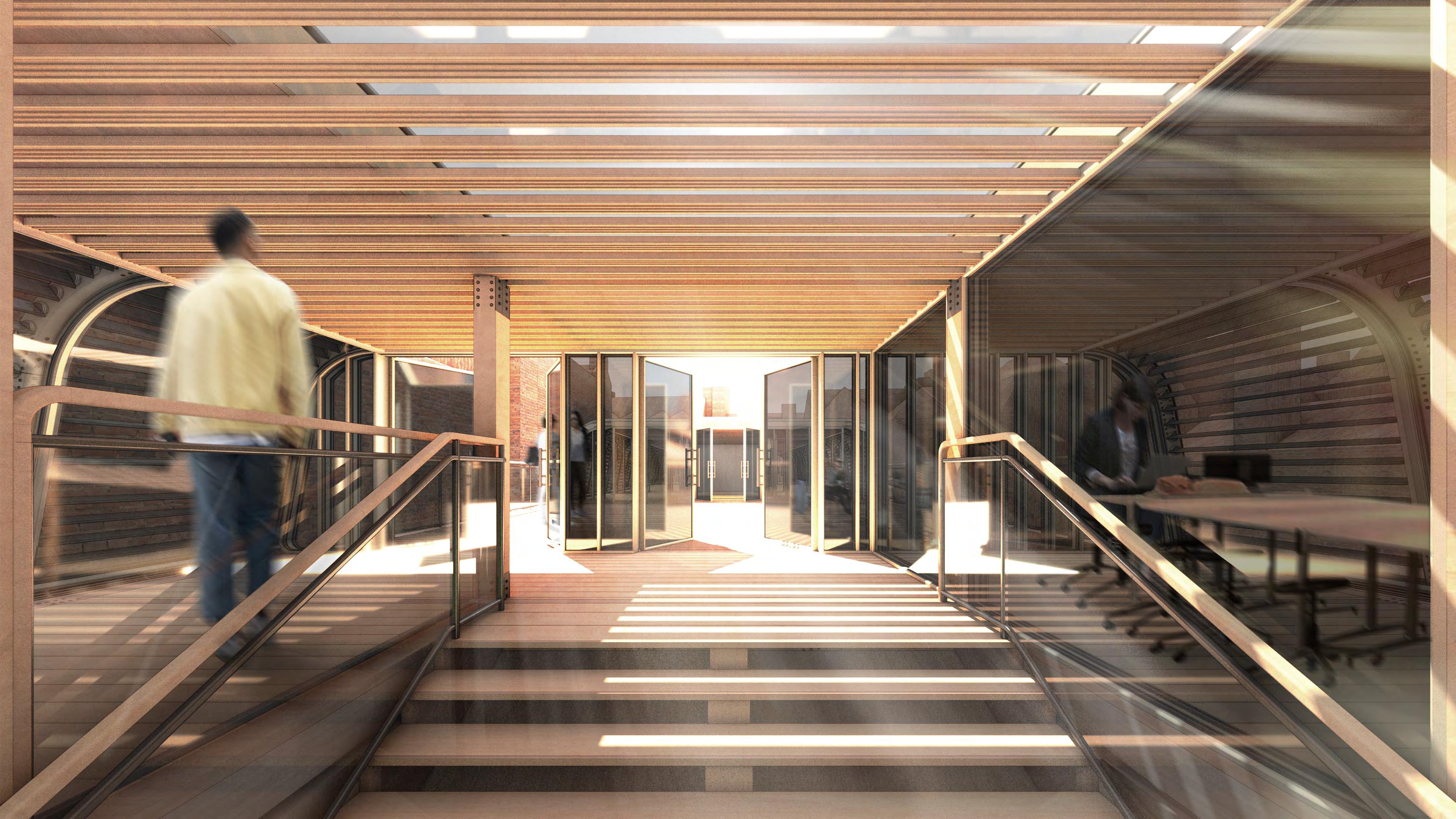
FINAL DRAWINGS EntrancE
DRAWINGS ntrancE
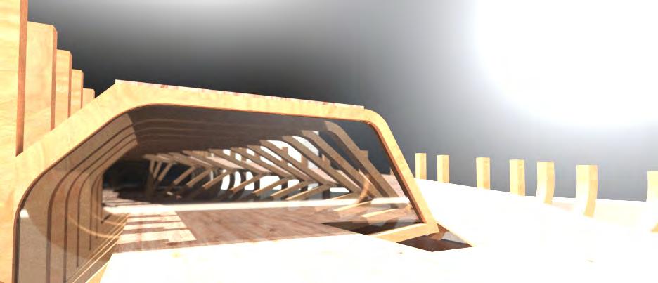
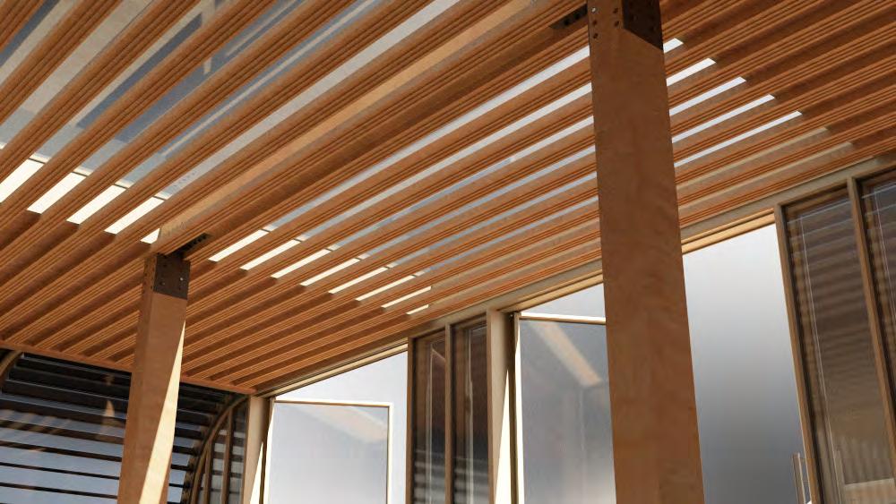
FINAL DRAWINGS roof
DRAWINGS Lobby

FINAL DRAWINGS Exhibition
DRAWINGS xhibition

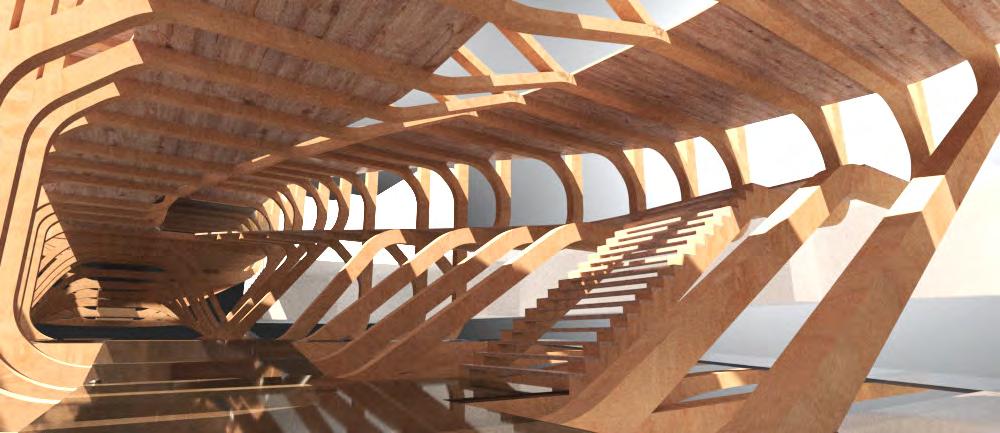
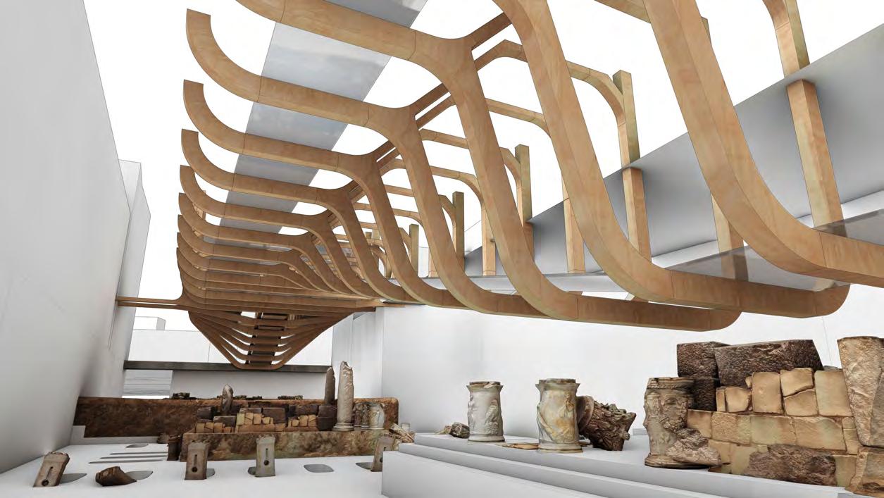
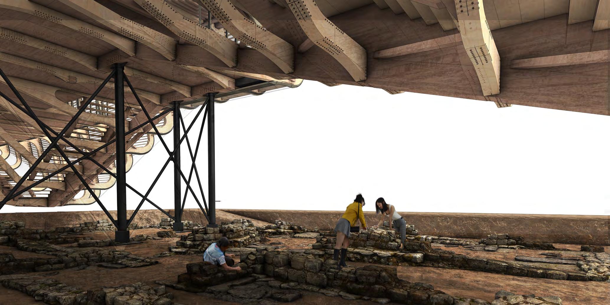
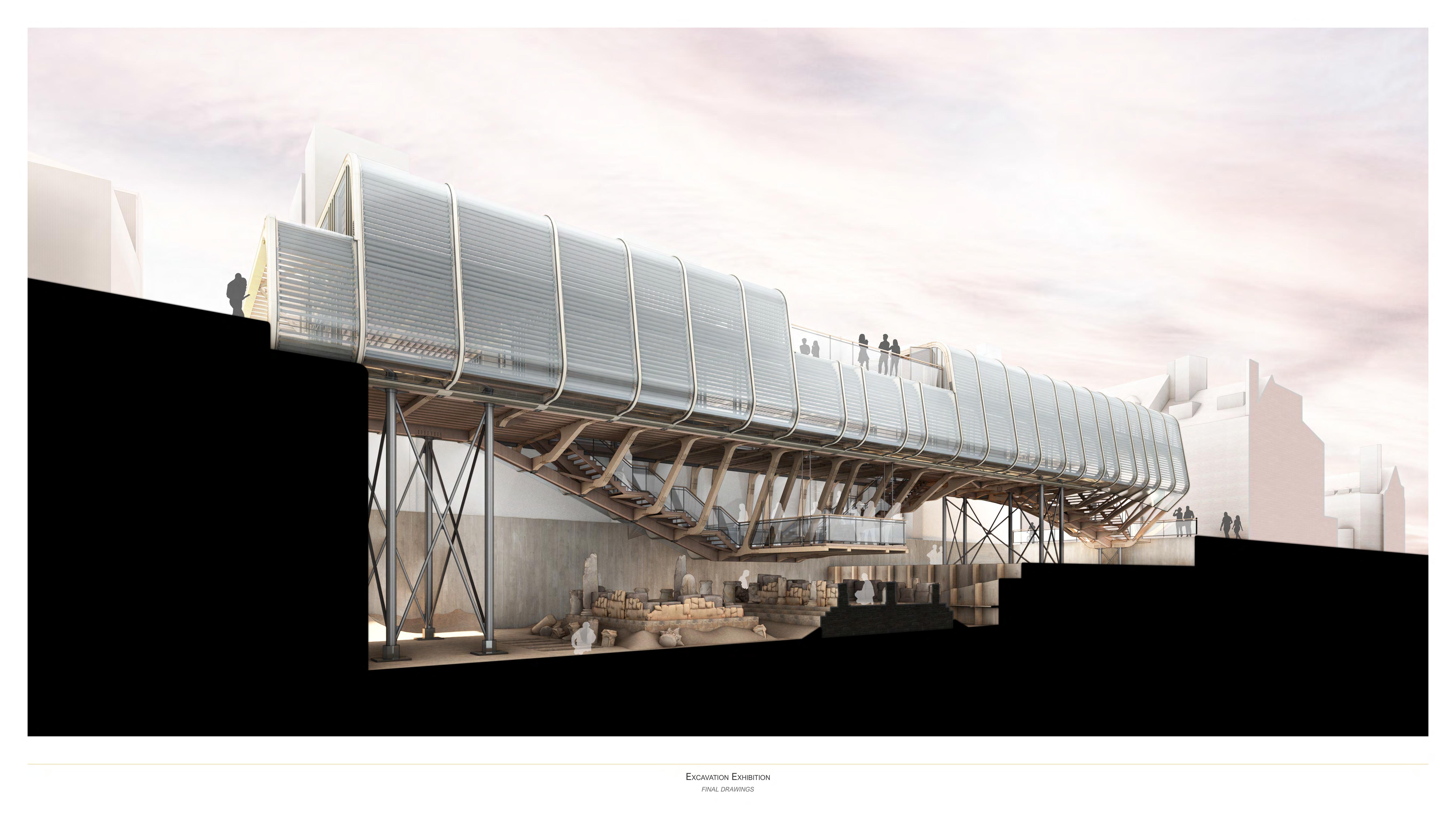
FINAL DRAWINGS Excavation
DRAWINGS xcavation
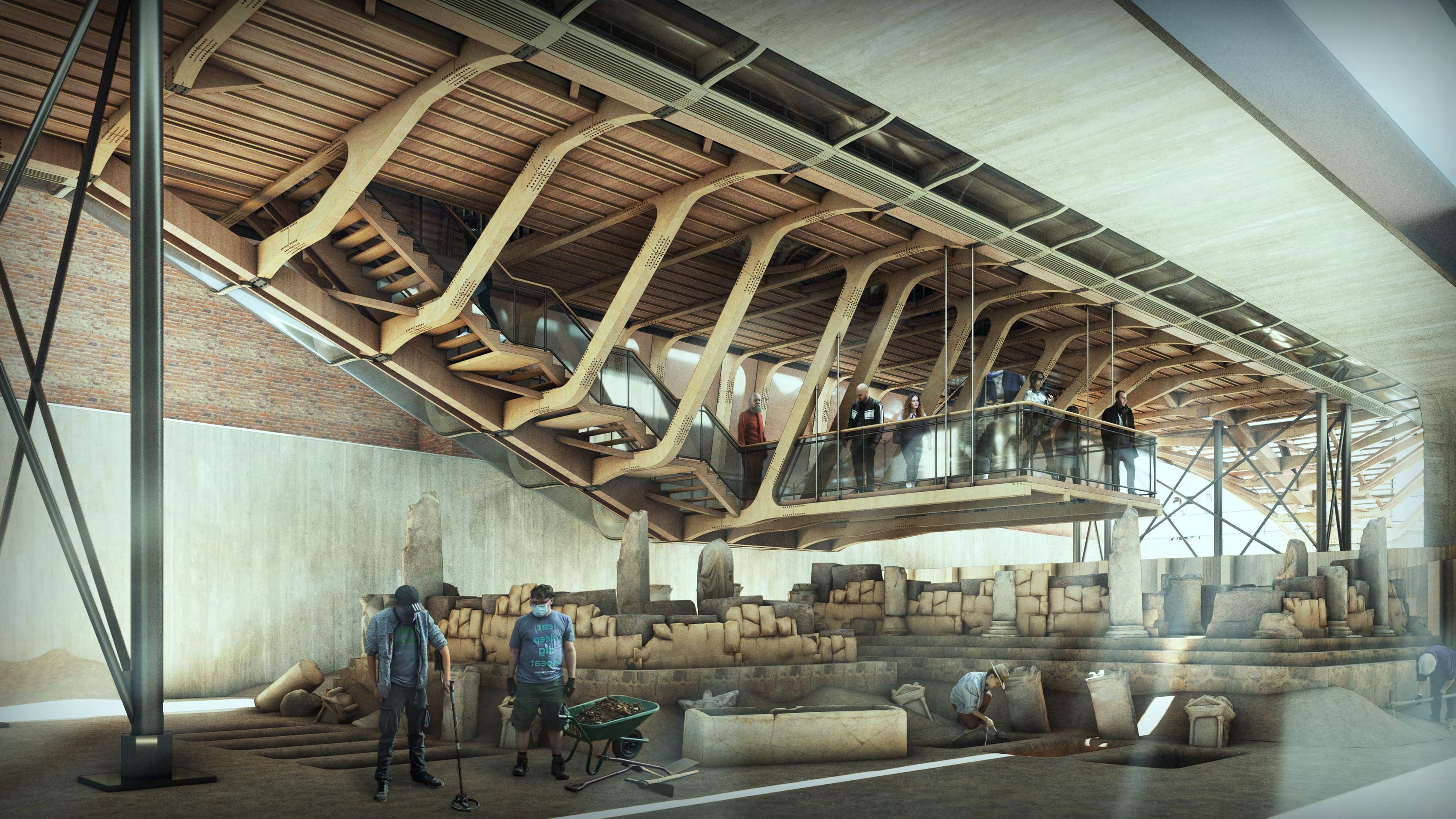
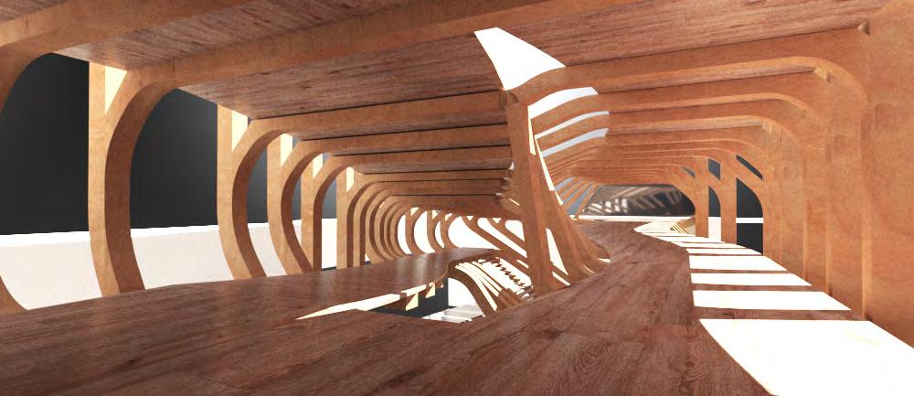
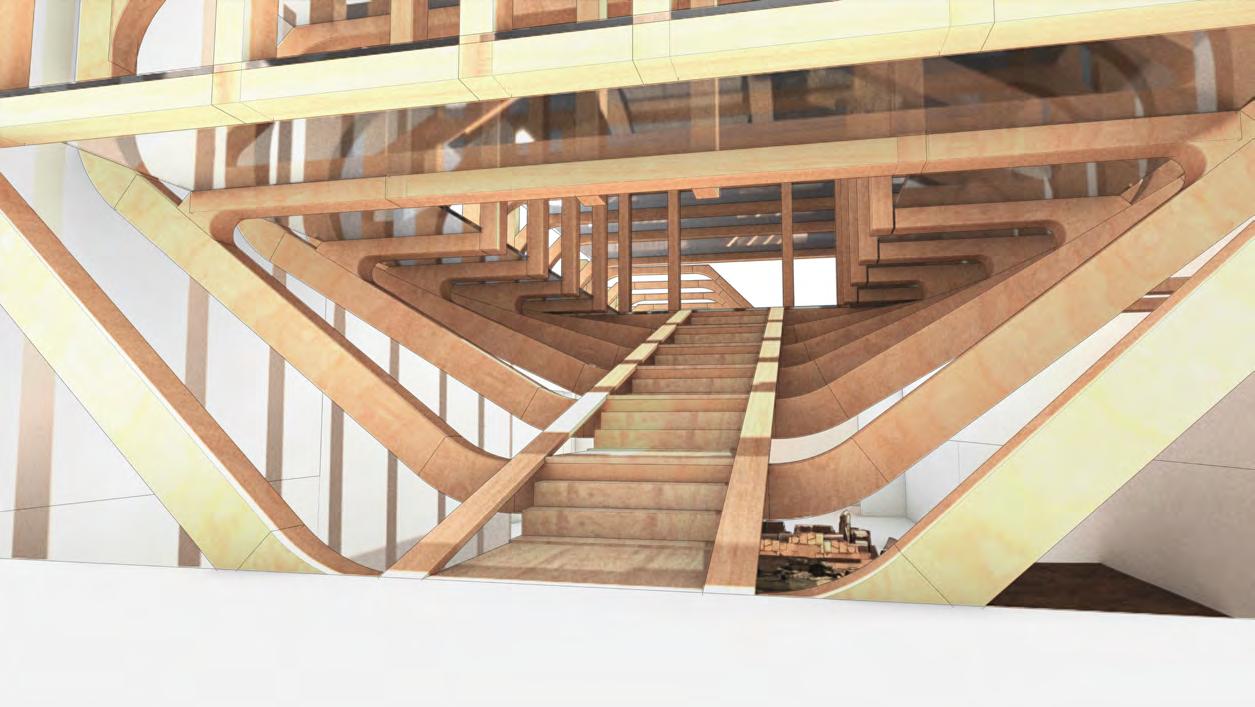
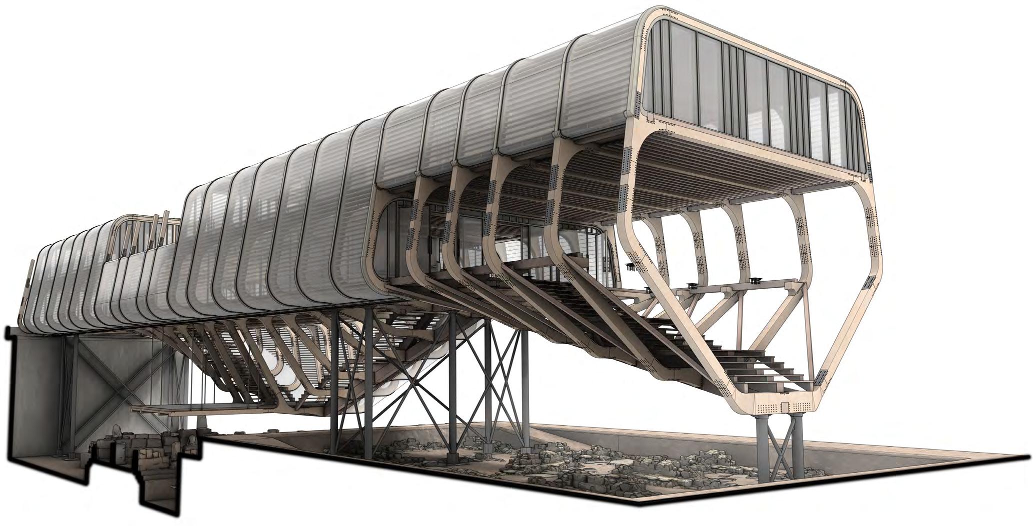
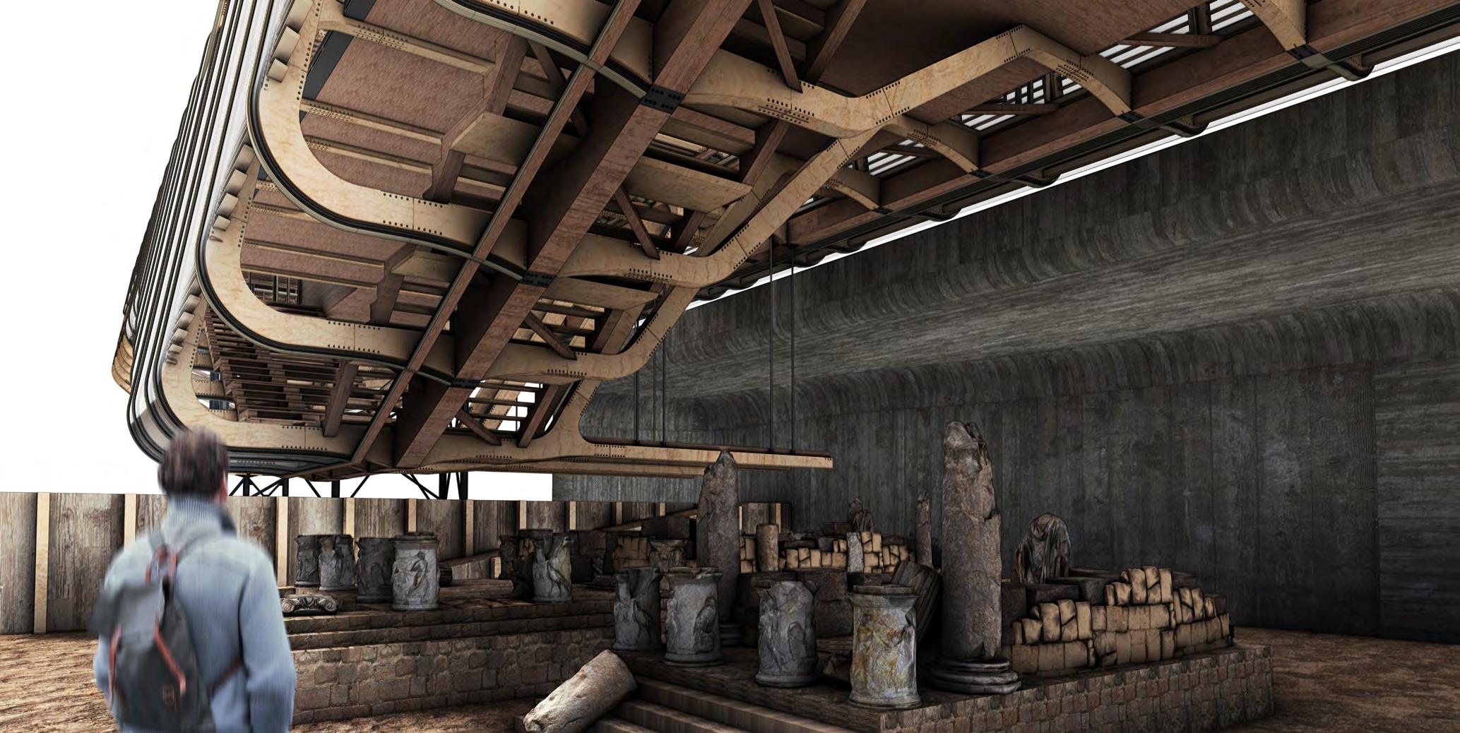
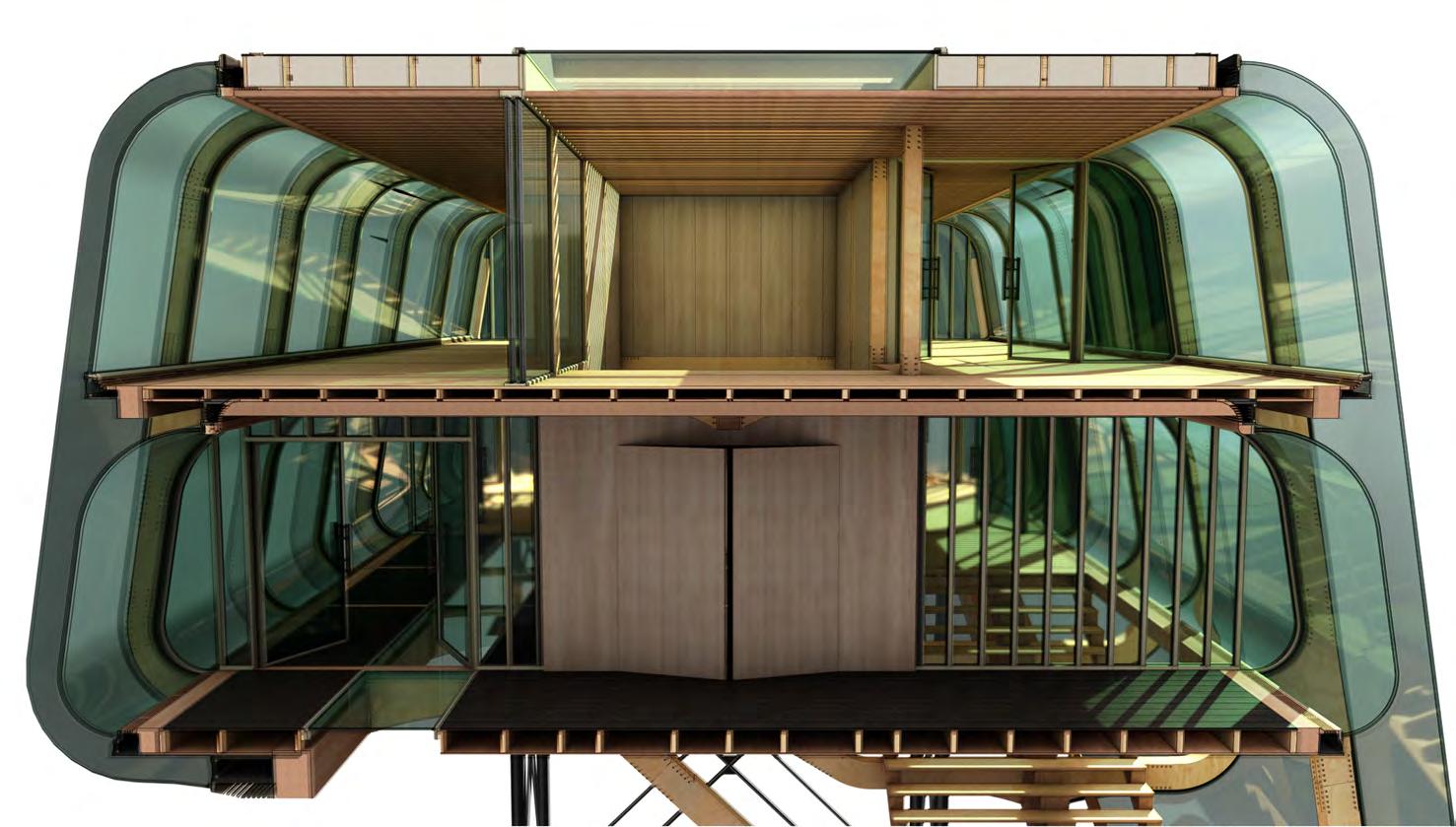
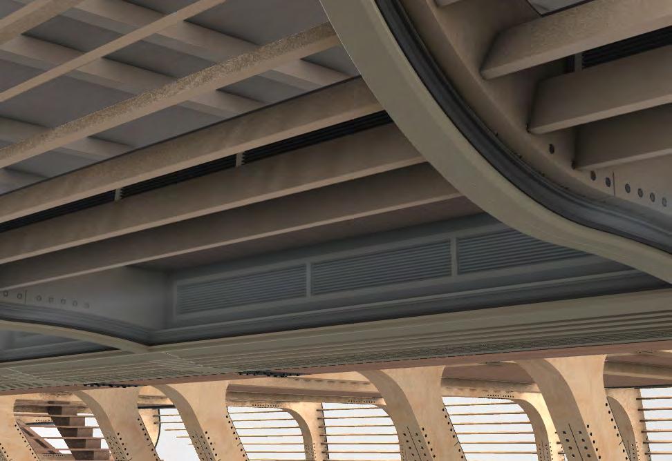
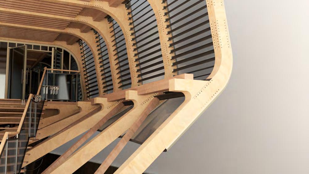
FINAL DRAWINGS UndErbELLy
DRAWINGS ndErbELLy
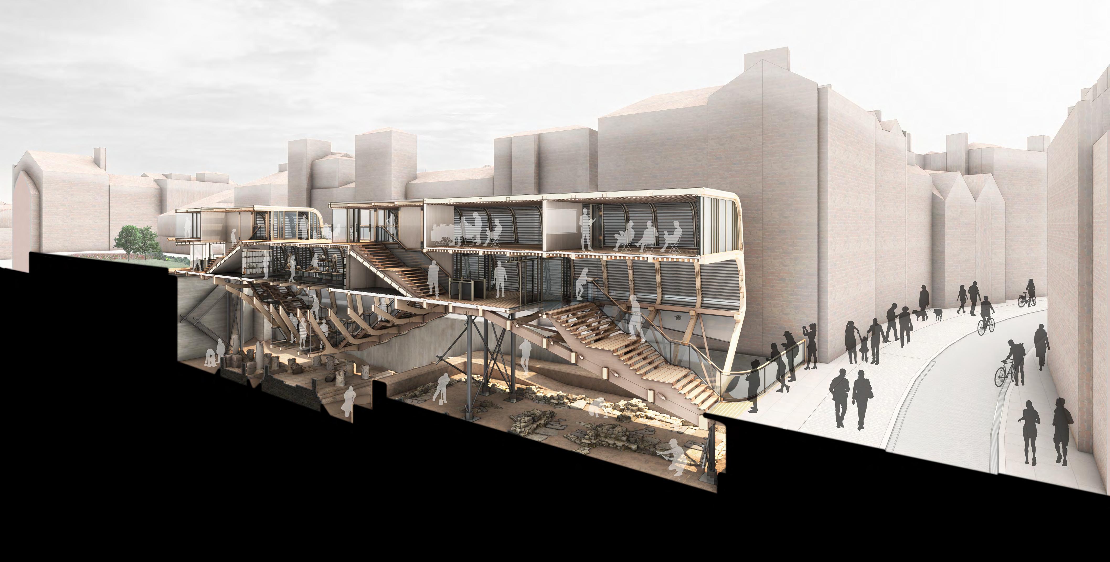
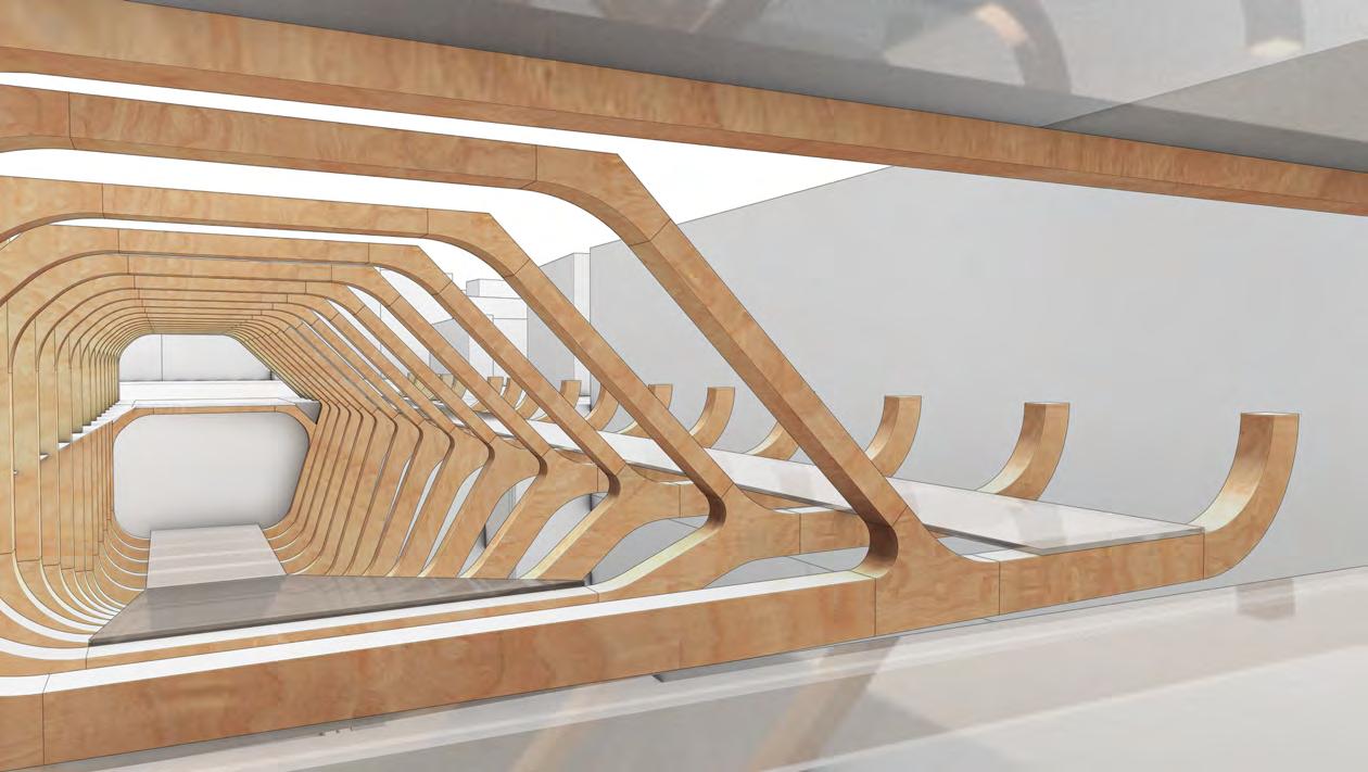
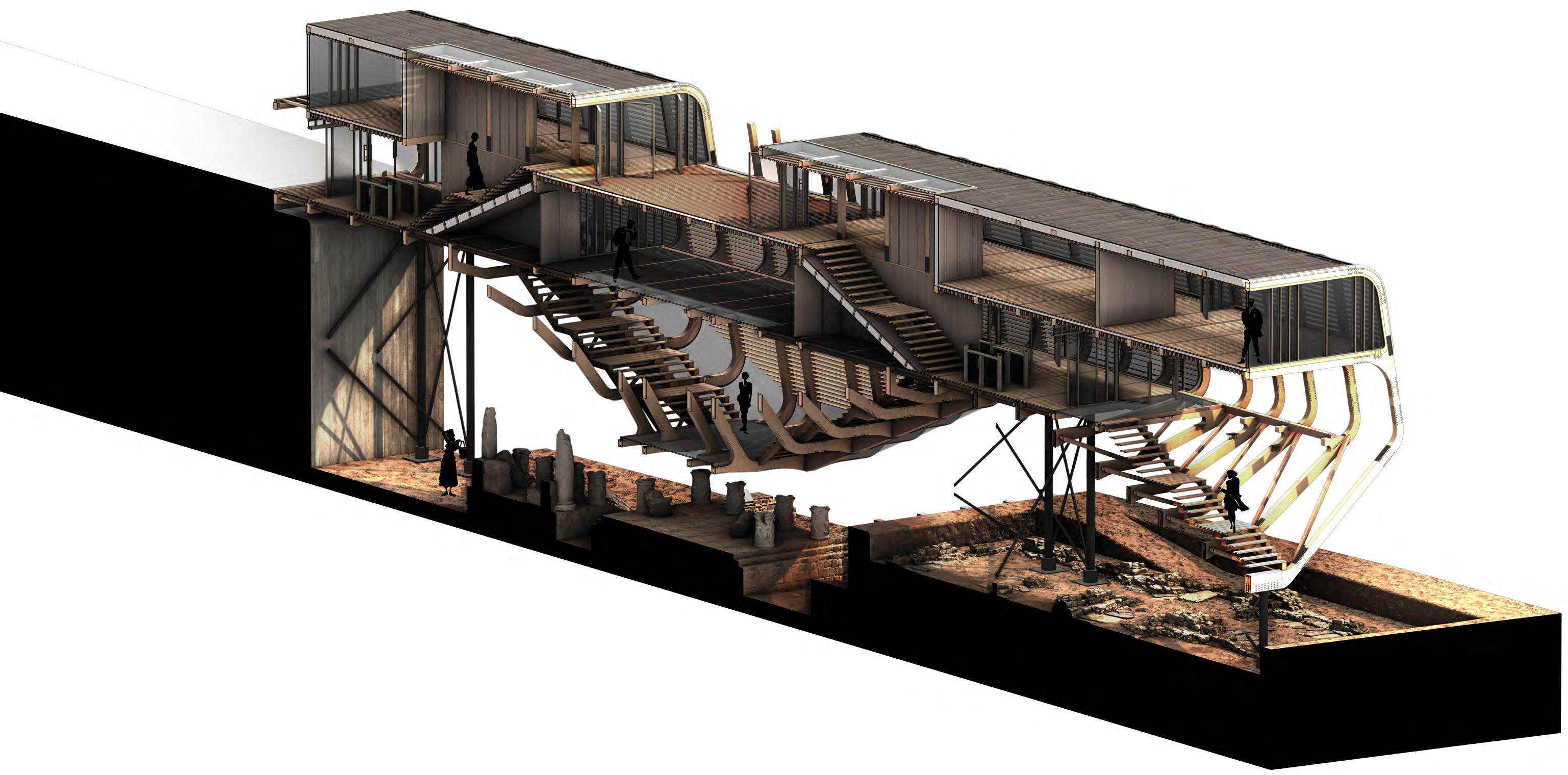
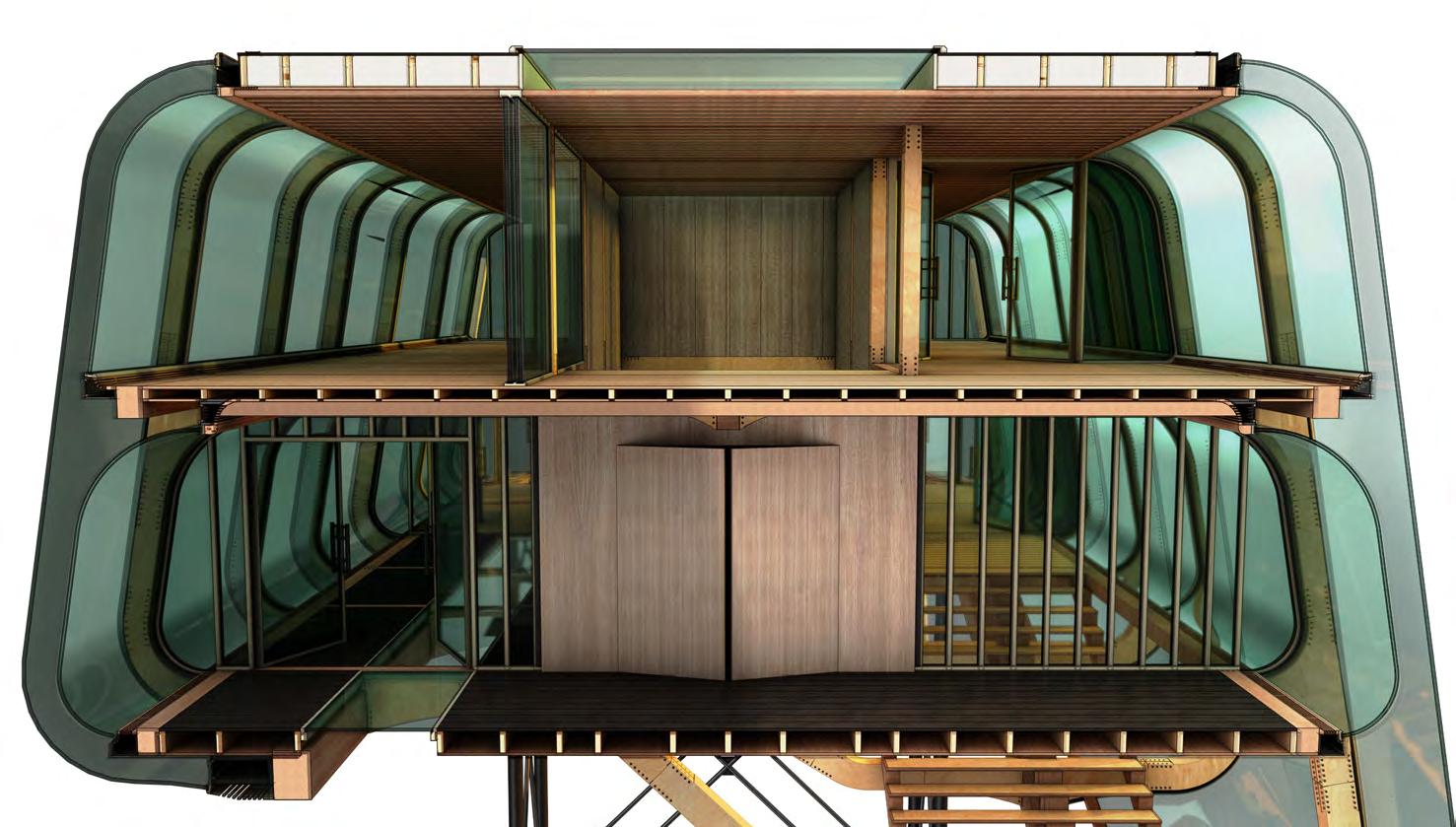
FINAL DRAWINGS SEctionaL
DRAWINGS EctionaL
All work produced by Unit 14
Unit book design by Charlie Harriswww.bartlett.ucl.ac.uk/architecture
Copyright 2021
The Bartlett School of Architecture, UCL All rights reserved.

No part of this publication may be reproduced or transmited in any form or by any means, electronic or mechanical, including photocopy, recording or any information storage and retreival system without permission in writing from the publisher.

-

@unit14_ucl UNIT


 Cover design by Charlie Harris