personal transport vehicle wheel two SELF-BALANCING
Por: J. M. Tejeda-Velázquez* · A. J. Picón-Febres-Cordero · L J. Sánchez Vargas
RESUMEN
Este trabajo describe el diseño y desarrollo mecatrónico para conformar un vehículo de transporte personal con capacidad de auto-balanceo. El algoritmo genérico de control se desarrolló en MathWorks -matlab y Simulink, con base en la traducción de lenguajes entre plataformas hacia un microcontrolador Arduino mega . El sistema de captura se compone de un módulo de medición inercial que incorpora un acelerómetro y un giroscopio, un filtro complementario para la obtención de la posición angular del modelo, y de un filtro de Kalman para suavizar los picos en la señal debidos al ruido.
ABSTRACT
This work shows the design and mechatronic development to build a personal transport vehicle with self-balancing capacity. The generic control algorithm was developed in MathWorks - MATLAB and Simulink, based in the language translation between platforms towards an Arduino MEGA microcontroller. The sensing system is composed of an Inertial Measurement Unit (IMU) that incorporates an accelerometer and gyroscope, a complementary filter to obtain the model’s angular position, and a Kalman filter in order to smooth noise peaks within the signal.
PALABRAS CLAVE
Vehículo autobalanceado
Diseño mecatrónico
KEYWORDS
Self balancing vehicle
Mechatronics design
DEVELOPMENT
In a daily life situation, suppose that you stand up and lean forward, so that you are out of balance, you probably won't fall on your face because of your instantly motion reaction. Your brain knows you are out of balance, so it automatically triggers you to put your leg forward and stop the fall. If you keep leaning forward, your brain will keep putting your legs forward to keep you in an upright position. Instead of falling, you walk forward, one step at a time. The two wheel self-balancing vehicle does pretty much the same thing, except it has wheels instead of legs, a motor instead of muscles, a microcontroller instead of a brain and a set of sophisticated sensors instead of an inner-ear balancing system. Like your brain, the vehicle knows when you are leaning forward or backwards and to maintain the balance, it turns the wheels just at the right speed.
THE TWO WHEEL SELF-BALANCING VEHICLE DOES PRETTY MUCH THE SAME THING, EXCEPT IT HAS WHEELS INSTEAD OF LEGS, A MOTOR INSTEAD OF MUSCLES, A MICROCONTROLLER INSTEAD OF A BRAIN AND A SET OF SOPHISTICATED SENSORS INSTEAD OF AN INNER-EAR BALANCING SYSTEM.
CONTROL DESIGN
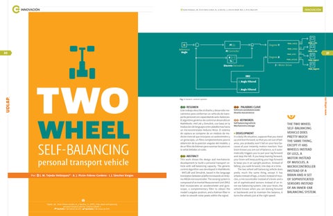
In order to control the self-balancing system, it is necessary to compensate an «error signal» to maintain equilibrium. Two main signals named reference angle and feedback are compared to obtain the error signal and therefore compensate accordingly. The reference signal represents the angle in which we want to maintain the plant, which is zero degrees vertically. The other signal coming from the sensor, called the feedback signal, represents the angle of inclination of the vehicle’s driver with respect to the gravity vector. It was necessary to implement a PID controller, which is proportional, integral and derivative with respect to the error signal; the proportional part helps the system to have a faster response and in case of the self-balancing vehicle, it is crucial to avoid unstable behavior. However, if we have a fast response, the system could have a high percentage of overshoot not achieving the exact point of equilibrium. For this reason, a derivative controller is used and
the integral part finally gives precision in the steady state functioning of the vehicle.
SIGNAL ACQUISITION AND PROCESSING
The feedback signal was acquired from an Inertial Measurement Unit - IMU (gyroscope plus accelerometer), to communicate with the microcontroller by using the I2C protocol, this is easily implemented with RASPlib library in Simulink. The next step was to design a mathematical model that can process and filter the IMU signals (linear axial acceleration and the angular velocity of the three axis) to obtain the angular position of the vehicle. The way to design the aforementioned model is resumed to the application of basic mathematical and digital operations, such as: signal delay elements, trigonometric angle relationships, data type conversions, multiplication or gain elements and sums. These basic operations combined with signal processing theory, made possible an accurate
Tejeda-Velázquez, J.M., Picón-Febres-Cordero, A.J., & Sánchez, L.J. Entorno UDLAP, Núm. 2, 20-23, Mayo 2017
HE OTHER SIGNAL COMING FROM THE SENSOR, CALLED THE FEEDBACK SIGNAL, REPRESENTS THE ANGLE OF INCLINATION OF THE VEHICLE’S DRIVER WITH RESPECT TO THE GRAVITY VECTOR.
signal interpretation and conversion to obtain a «simple angle».
A Kalman filter was used as a last and important stage of the filtering process in order to reduce peaks added to the signal due to a rapidly variable angular position or vibration captured by the IMU to prevent unstable behavior.
Finally, it is important to mention that the inclination achieved be the user over the self-balancing vehicle can be projected over the x and y axis on a plane; hence, these are the only sensor readings needed.
ACTUATORS: POWER MOTOR DRIVERS
DISCUSSION OF RESULTS AND CONCLUSIONS
The main goal of the project was accomplished; however, it is important to point out the following aspects:
• Obtaining a clean feedback signal from the sensor was a big challenge because of the system vibrations
• The wheel’s transmission chain employed, presented tension and backslash developed in the gears used to transfer power from the motor to the wheels. This is a nonlinear behavior not taken into account
• The tests showed an optimal equilibrium condition obtained from experimentation, given the lack of a mathematical characterization due to missing parameters
REFERENCIAS
• Nise, N. S. (2000). Control systems engineering. Nueva York John Wiley.
After comparing the feedback and reference signals, we obtained the error signal which passes through the PID controller in order to drive the vehicle: 70% is used for equilibrium, letting the remaining 30% to be applied for rotational purposes. As the signal flows into both motor drivers, it is translated to a Pulse-Width Modulated (PWM) voltage signal to supply the motors with the required thrust to balance the system. Both drivers have the same functionality, but each one is characterized experimentally to set up an initial breakup point to defeat the motors static inertia. Besides it, it was necessary to translate the vehicle wheels rotation degrees to PWM voltage by a factor of 255/10, in order to set the maximum limit of rotational displacement to 10°, given the maximum PWM limit is 255, also seen as 5V in Arduino’s microcontroller output.
• Hurst, J. (2017). Rensselaer Arduino Support Package. En línea. Obtenido el 1 de enero de 2017 desde: http://homepages.rpi.edu/~hurstj2/
Antonio José Picón Febres Cordero Estudiante del 8º semestre de la Licenciatura en Ingeniería Mecatrónica por la Universidad de las Américas Puebla, con un promedio acumulado de 9.8. Docente de robótica para niños de primaria, secundaria y preparatoria desde agosto de 2016 en el proyecto «Piensa». Actualmente participa en el desarrollo de una silla-exoesqueleto para los trabajadores en la línea de producción de la VWdM. antonio.piconfo@udlap.mx
Juan Manuel Tejeda Velázquez Estudiante del 8º semestre de la Licenciatura en Ingeniería Mecatrónica por la Universidad de las Américas Puebla, con un promedio acumulado de 9.5. Ex-miembro del Programa de Honores por el proyecto de energías renovables. Docente de robótica para niños de primaria, secundaria y preparatoria desde agosto de 2016 en el Proyecto «Piensa». Actualmente participa en el Desarrollo de una silla-exoesqueleto para los trabajadores en la línea de producción de la VWdM. juan.tejedavz@udlap.mx
Luis Javier Sánchez Vargas Estudiante del 8º semestre de la Licenciatura en Ingeniería Mecatrónica por la Universidad de las Américas Puebla, con un promedio acumulado de 8.6. luis.sanchezvs@udlap.mx