TRT x C&R ESS 4x8 Low Loader Trailer Specification Manual
Contact Details
Service
Please contact the TRT service department if you have any questions. Please list the model number and Vehicle Identification Number (VIN) in all correspondence.
New Zealand
Phone: 07 849 4839
Email: service@trt.co.nz
Emergency Call Out 24/7
Phone: 0274 726 394
Australia
Phone: +61 7 3890 8800
Email: service@trtaust.com.au
After Hours Support
Phone: 1800 849 029
Technical Support
Contact your local distributor.
Supplied Trailer Information
Supplied documentation (electronic) comprises the following: Operating Procedure, Risk Analysis, Rated Capacity, Parts Catalogue and Service Manual.
Modifications to the Trailer
Any modifications made to the Trailer must be approved by manufacturer. Failure to gain written approval will void warranty.
Vehicle Identification Number (VIN)
When corresponding with the manufacturer the VIN should be included, it will be used to identify the trailer. (VIN is located at the front of the trailer.)
Manufacturer
TRT Tidd Ross Todd Ltd
48 Maui Street
Pukete Industrial Estate
Hamilton 3200, New Zealand
Phone: +64 7 849 4839
Fax: +64 7 849 3628
trailers@trt.co.nz www.trt.co.nz
TRT Australia 1028 Lytton Road, Murarrie, QLD 4172
Australia
Phone: +61 7 3890 8800
AU Parts: parts@trtaust.com.au
AU Service Group: service@trtaust.com.au www.trtaustralia.com.au
WIDENS: 3090 CLOSED 4430 OPEN BRAKE KIT: TRANSPECS
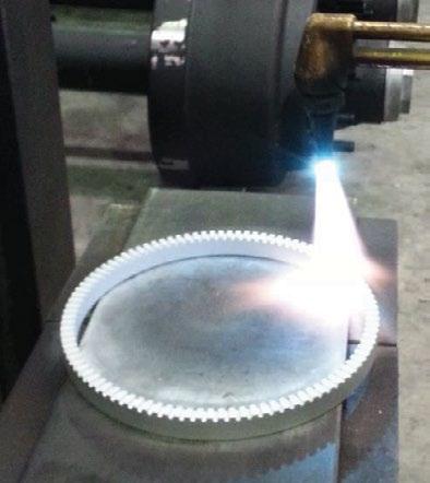
3. Auto Greasing
3.1 Gooseneck
This trailer is fitted with a GROENEVELD auto greasing system. Service and technical information is covered in section 8 of this manual.
3.2 Wheel Assembly
4. Schematics
4.1 Electrical
4.1.1 Trailer Plan View
WIRING DRAWING
E Optional features that can be enabled through Bodas Service.
E 2 11/11/2022 Added Push-Pull Brakes outputPg 03 Added missing pin numbers for ground pins on RC12-10/30Pg 05
1 08/11/2022 Common wiring drawing for all Gen 4 trailers
E 3 02/12/2022 Updated pinout for 3-6 Axle Aux RC12-10/30Pg 07 Removed incorrect/extra input pins (SS FRONT LEFT & SS FRONT RIGHT)Pg 06
E 4 06/12/2022 Added Site Manual Lock Switch input pin to PT Clipon (Pg 09) and HT Clipon (Pg 11) Added Sidestep Legs to Aux RCPg 06
E 5 24/01/2023 Added Sidestep DiverterLegs as a panel input to the Aux RC12-10/30. Pg. 06
E 6 14/06/2023
Removed Detect Pins input pinsPg 04 / 09 / 11 Corrected Diverter output pins and Axle 6 Power output pinsPg 03 Removed Widening Float output pinPg 07 Added CAN locations for Ride-Height inclinometersPg 05 / 13 Sakya E
7 23/08/2023 Corrected incorrect drawing for Diverter outputsPg 03
8 18/03/2023 Added PTO Interlock SwitchPg 03
E 9 30/04/2024 Updated CAN locations for Ride-Height inclinometersPg 05 / 13 Updated Pg 07
10 31/05/2024 Updated Auxiliary pinout to include Rear Amber lightsPg 07
3-6 AxleStrRC28-14/30Power VSS_1
3-6 AxleStrRC28-14/30(2)
NOTE: **OUT_23 is used to provide power to OUT_41 and OUT_42 only in the House Trailers.** **In Platform Trailers, OUT_23 is used for widening, and power for OUT_41 and OUT_42 are connected directly to battery voltage.***
1-2 AxleHouse Trailer ClipOnRC10-10/31
connector
CANBUS LAYOUT
4.1.5
GEN 4 Platform Trailer - Looms
and Plugs
4.1.6 Component Description and Placement - Gooseneck Section
Component Location
15-pin Plug Front Panel
1st lights Junction Box
Left Side - on lower accumulator shroud
Function and Notes
Trailer lights, Screen power and CAN
Use Road train cable from front plug to 1st junction box
All Gooseneck side lights terminate to BROWN
(2mm) blue to main enclosure and (4mm) Blue back again for leg lights
7-core cable to rear, exits box
Powerpack On top of Gooseneck Yanmar 4TNV 98
Revs set at 1800rpm and 2400 rpm.
Rexroth 28cc pump with electronic load sense controller
12 volt start and charge
Battery isolator on front of powerpack when specified
Battery pack for control system Right side of Gooseneck under Powerpack
2 x 12v AGM (Glass-pack) batteries
A 12-24volt charger uses the powerpack battery to charge the controll batteries
A re-settable circuit breaker controls the out current to the main enclosure
12v Fuse for input
24v fuse for charge
Main electrical enclosure
Right side of Gooseneck
Remote Reciever Right side of Gooseneck on main enclosure
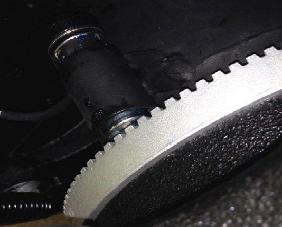
Encoders Inside gooseneck at Slew Ring
Contains trailer ECU’s and motor control (start, stop, Charge, revs etc relays)
Termination points for all major data and command supplies
Has 12v, 24v and 5v supplies insde - use multimeyters for diagnostic proceures
24v Isolator on rear of box
Ignition sw. on rear of box
Recieves remote controller commands and send commands to trailer ECU’s via the CAN system
Measure angle of truck to trailer and relay information to steer controller main enclosure
Component Description and Placement - Main Chassis
Component
Location
Function and Notes
7-core loom Left side Left side Lights
7-core loom Right side Front Right side lights
10-pin socket at Main Enclosure
Plug-in point for tethered remote
Steer Control Valve Centre of trailer inside metal cover 1 per side
1 per side Fuses in enclosures for each axle
EnclosureTempersonic Junction
Auxillary control valve
Wheel speed sensors
Front of trailer main chasis on A-trailer
Steer ram sensors are called Tempersonics.
All tempersonic cables terminate at the tempersonic enclosure then travel to the main enclosure
Terminate at the tempersonic enclosure then travel through a shielded 2 core to the main enclosure
Controlls the suspension, Widening, clip-on rams, Ramps, and othe functions when specified
TMC Australia’s policy is one of continuous development, we therefore reserve the right to change or modify the specifications without notification.
TMC Trailer Unitised Bearing Axle Service Manual UB82
RECOMMENDED SERVICE SCHEDULE.
First Service 500 km or on Delivery:
Check torque settings of all wheel nuts - On delivery. - After all wheel changes
Every 5,000 km:
Check and adjust the brakes fitted with manual slacks, check brake linings for wear. Auto slacks only need to be adjusted during initial installation and during a brake change
Every 25,000 km:
Lubricate slack adjusters and camshaft bushings using an EP2 type grease or equivalent.
Every 100,000 km:
With the axle end lifted rotate the hubs and determine if the wheel bearing has excessive movement and noise. Listen for worn bearings that make a low-pitched grinding sound while the hub is rotated. The wheel rims will amplify the noise if assembled.
If the bearing is noisy, check the bearing endplay This should only be used as a guide as the clamping force sets the bearing adjustment.
To confirm the actual bearing endplay, use a dial indicator attached to the end of the spindle and record the dial indicator reading. This should be in between 0.01 to 0.13mm (0 to 5 thou).
If the bearing endplay is out of specification, then the axle spindle nut tightening procedure will need to be actioned. If in doubt, please contact TMC or its approved service outlet.
Inspect hubcap and check for signs of damage to the gasket. Replace gasket if damaged. Check grease for any contamination or discolouration. If grease is badly discoloured, this should be replaced.
Check inboard hub seal for leakage or damage, remove hub and replace seal if necessary. Check the brake components for wear. Replace if necessary.
Note: TMC’s range of “LMV”, “LMVS, “SL10”, and “SL10 VS” suspensions, TN, TP, UB90 and UB82 trailer axle combinations are generally designed for operating on clean paved r oads Although occasional use on graded or gravel roads is acceptable, for equipment that is regularly used “off-road” or “off-highway” TMC recommends that service intervals shou ld be halved In extremely severe operating conditions, weekly and in certain cases even daily inspections of the equipment may be required to ensure safe and correct operation of the suspension and axle combination.
10 Stud x Ø225
PCD M22 Hub Ø335 x 160 'S' Cam Drum Brake
TMC Trailer Unitised Bearing Axle Service Manual UB82
APPLICATION OF GREASE INTO HUB.
1. It is required to partially fill the cavity in between the seal and bearing with grease. This additional grease will extend the seal and bearing life by preventing contaminants entering into the bearing assembly. If there are any questions, please contact TMC engineering.
Type of grease: Mobil grease XHP 222 or equivalent lithium complex NLGI grade 2 Grease.
Quantity: 50g to 100g.
APPLICATION OF GREASE ONTO SPINDLE SURFACE.
1. Apply Anti-fretting grease SKF # LGAF 3E or equivalent to the spindle surface
AXLE SPINDLE NUT TIGHTENING PROCEDURE.
1. Apply a light film of anti-seize grease to the spindle bearing surface. Install hub ensuring seal is not damaged during installation. Apply a light film of anti-seize grease to the spindle thread and fit the axle spindle nut (part 812015). Tighten to 1000 Nm.
2. Fit the axle lock tab washer (part 812017) onto the axle spindle
3. Fit the axle spindle lock nut (part 812016) onto the axle spindle and tighten to 800 Nm.
4. Bend the lock tab washer tabs both inwards over the axle spindle nut and outwards over the axle spindle lock nut to ensure they cannot move. Apply a light smear of grease over all the parts on the axle spindle end to prevent rusting. Finally refit the axle hubcap and gasket onto the axle hub end. Tighten the hubcap studs (M8) to 20 / 25 Nm.
TMC Trailer Unitised Bearing Axle Service Manual UB82
TORQUE SETTINGS CHART.
Axle spindle nut M80 - 1000 Nm.
Axle spindle lock nut M80 - 800 Nm.
Wheel nuts:
M22 ISO wheel studs - 550/600 Nm
Hub Cap Bolts: M8 studs - 20/25 Nm.
Note: Dry torque settings are shown above. Wet torque settings except the spindle nut torques are a 30% reduction of the dry torque settings (top torque values) with a coating of lubricated threads using a copper or nickel anti-seize etc.
WELDING TO TMC AXLE BEAMS.
Recommended welding procedures:
1. Before any welding is conducted on the axle tube, the axle tube must be pre heated to 150 – 200C locally at the area to which the welding is to be done Caution: Do not apply excessive heat to the axle tube.
2. All welding is to be applied to the axle tube as near as possible to the axle’s neutral axis. Do not weld circumferentially around the axle tube.
3. All welds must be conducted using low hydrogen rods or an approved equivalent MIG process. Grounding/earth wire must be attached directly to axle beam not to the hub or components.
TMC Trailer Unitised Bearing Axle Service Manual UB82
BRAKE ADJUSTMENT – MANUAL SLACK ADJUSTERS.
‘S’ Cam brakes are adjusted by the manual slack adjusters fitted to the camshafts on the axle.
1. With the spring brakes released, adjust the slack adjuster until the brake linings contact the brake drum. This is done by rotating the 19mm adjusting bolt clockwise. Note: Locking collar slack adjusters are also used depending on the axle model. The locking collar must be pushed down before the adjusting bolt can be adjusted. Ensure the locking collar springs back and locks the adjusting bolt after brake adjustment has been completed.
2. Adjust the 19mm hexagonal nut counterclockwise approximately ¼ turn until the hub just rotates freely with no brake drag
4. Finally check that with the brakes released and applied that the angle between the brake chamber push rod and slack adjuster is greater than 90 degrees. The angle can be adjusted by screwing the push rod clevis backwards or forwards along the push rod thread to achieve the correct angle. When finished always check that the push rod clevises lock nut is tightened.
Released Applied
19mm Hex adjusting nut
BRAKE ADJUSTMENT - MANUAL SLACK ADJUSTER.
BRAKE ADJUSTMENT – AUTOMATIC SLACK ADJUSTERS.
‘S’ cam brakes fitted with automatic slack adjusters should require no manual adjustment after the initial Installation on the axle or initial re adjustment of the brakes after brake relines. All automatic slack adjusters have a specific set up and installation procedure as specified by the automatic slack adjuster manufacturer. This procedure must be adhered to. If in doubt contact the manufacturer of the automatic slack adjuster or the manufacturer’s agent for these specific procedures. Generally, automatic slack adjusters must be re adjusted similarly to the manual slack adjusters on initial installation or after brake relines.
Caution: Please refer to the manufacturer’s recommendations.
TMC Trailer Unitised Bearing Axle Service Manual UB82
SPARE PARTS – Axles with 335 diameter x 160 wide ‘S’ cam brakes
PFRD-U82-136 : Ro8 and Platform Axles
TMC Trailer Unitised Bearing Axle Service Manual UB82
SPARE PARTS – Axles with 335 diameter x 160 wide ‘S’ cam brakes
PFRD-U82-136 : Ro8 and Platform Axles
Item Part Number
1 812006 Hub cap - grease
2 812007 Hub cap gasket
3 9HBM08125020 Hub cap stud M8 x 20 long
4 9SWM08 Spring washer M8
5 812015 Axle spindle adjusting nut
6 812017 Axle spindle lock tab washer
7 812016 Axle spindle lock nut
812055 Brake spider 335x210
9 812012 (s) (a) Brake drum – 10 stud x 225 pcd 335x160 notched
8180769 Auto slack adjuster 10 spline multi - straight 8180960 Auto slack adjuster 10 spline 5/8” offset RH
8180961 Auto slack adjuster 10 spline 5/8” offset LH
27 813103/152L Camshaft 10 spline – 152 long LH
813103/152R Camshaft 10 spline – 152 long RH
812060L Camshaft 10 spline – 116 long LH
812060R Camshaft 10 spline – 116 long RH
28 810122 Camshaft washer 1 ½”
29 810121 Camshaft circlip 1 ¼”
31 810061 Outer cam bush 34 810082/01 Camshaft seal 1 ½” 35 9GNM0845 Grease nipple M8
36 813110-07/08 Brake lining set
Note:-
Optional
810300/80 ABS axle kit – 80 tooth
810169-80 ABS pole wheel – 80 tooth 810001 810000 Brake hardware kit 335 x 210 (per wheel end)
1) Hub assembly 812005 (item 10) comprises all parts marked with *. 2) Part shown with (s) indicates this suits steel wheel fitment. Part shown with (a) indicates this suits alloy wheel fitment.
Description
ItemPart Number
20813126Brake shoe lined 335x160 –P brake
21800013Brake return spring retainer pin
22810092/01Anchor pin –P brake bolt on short
23812024Dust cover335 brake
249HBM08125020Dust cover bolt M8 x 20 long
25Contact TMCAxle beam assembly
26Contact TMC5/8" offset auto slack adjuster
810240LH5/8" offset manual slack adjuster LH
810240RH5/8" offset manual slack adjuster RH
27812060LCamshaft 10 spline –116 long LH
812060RCamshaft 10 spline –116 long RH
28810122Camshaft washer 1 ½”
29810121Camshaft circlip 1 ¼”
31810061Outer cam bush
34810082/01Camshaft seal 1 ½”
359GNM0845Grease nipple M8
36813110-07/08Brake lining set Optional
810300/80ABS axle kit –80 tooth
810169/80ABS pole wheel –80 tooth
Description
ItemPart Number
1812006Hub capgrease
2812007Hub cap gasket
39HBM08125025Hub cap stud M8 x 25 long
49SWM08Spring washer M8
5812015Axle spindle adjusting nut
6812017Axle spindle lock tab washer
7812016Axle spindle lock nut
8812055Brake spider 335x210
9812012 (s)Brake drum, 10 x 225, 335x160
812022 (a)Brake drum, 10 x 225, 335x160 notched
10812005Hub assembly (Including Item*)
11*812009Wheel bearing UB82 (BTH 0055)
12*810144 (s)Wheel stud –M22 ISO x 100mm (short)
810148 (a)Wheel stud –M22 ISO x 124mm (long)
13*812018Retainer ring wheel bearing
14*810135/02Hub seal 46300
15*810145Wheel nut –M22 ISO
16810094Cam roller
17810093Cam roller retainer –bolt on
18810101Brake return spring
19800002Anchor pin bush
Note:- Hub assembly 812005 (item 10) comprises all parts marked with *. 1. Part shown with (s) indicates this suits steel wheel fitment. Part shown with (a) indicates this suits alloy wheel fitment. 2.
6.4 ABS Pole Ring & Sensor
Subject: ABS pole ring and sensor block fitment on Drum brake axles.
TMC-140406
Service Bulle�n
Date: 30 08 2019
This Bulle�n specifies how to assemble a pole ring onto a hub and welding of the sensor block onto an axle
This applies to drum brake axles configura�on only
Contact TMC Australia for part numbers and quantity needed Type of hubs (alloy or steel) and brake configuration are required as the part numbers may vary.
Assembly of pole ring (Machined pole ring and Stamped pole ring )
Remove hub and drum from axle
Clean all corrosion and contamina�on from hub surface (where pole ring sits)
Machined pole ring - Heat up pole ring evenly using oxy acetylene torch for about 1 minute (DO NOT TOUCH POLE RING (HOT!) & DO NOT CUT/DAMAGE RING) and fit onto the back of the hub Ensure pole ring sits flat on hub
Stamped pole ring - Place ring onto back of the hub and gently tap ring into posi�on Visually inspect the ring to ensure that it is completely seated onto the hub. No hea�ng is required .
Page 1 of 4
Machined Pole Ring
Stamped Pole Ring
Hea�ng up pole ring using Oxy -Acetylene
Steel Hub Drum Brake with pole ring fi�ed
Service Bulle�n
Date: 30 08 2019
Assembly of sensor block
With hub and drum removed, clean all con taminants from axle beam and bearing edge shoulder . Posi�on sensor block at loca�on shown Dimension required from edge of bearing shoulder to front of sensor block are as follows:
o TN & TP = 22 +/- 1mm
o UB90 = 59 +/-1mm
o UB82 = 37 +/-1mm
Spot weld both sides of sensor block (at least 4mm con�nuous fillet weld) to axle beam. AVOID WELD
SPATTER ON OIL SEAL AND BEARING JOURNAL. CLEAN UP IF REQUIRED .
Page 2 of 4
Dimension from bearing shoulder to front of sensor block
Posi�on sensor block at loca�on shown
Assembly of sensor bush and leads
Assemble hub with pole ring onto axle and adjust bearings as required
Service Bulle�n
Date: 30 08 2019
Insert sensor bush into sensor block/brackets as shown Ensure correct orienta�on of bush
Lightly grease sensor and insert into bracket Push sensor leads un�l it contacts the pole ring.
(22.5” axle only) Drill a 19mm diameter hole on the right dust cover (see picture below) Drill a 19mm diameter hole on the opposite side for the le� hand dust cover.
Fit dust covers back onto axle and route lead thru the grommets Cable �e lead at block and another one behind dust cover. DO NOT KINK sensor leads.
Page 4 of 4
Cable �e lead at two posi�ons
6.5 Brake Drum Wear Limits
TMC-191001
Service Bulle�n
Date: 10 05 2019
Subject: Brake Drum Wear Limits.
This Bulle�n specifies acceptable Brake Drum Wear Limits used in TMC 335x210 and 420x180 drum braked axles
DRUM SIZE
335x210 (17 5”/19.5”)
420x180 (20”/22.5”)
PFRD-225-138
PFRD-245-138
PFRD-U82-138
PFRD-225-167
PFRD-245-167
PFRD-U90-167
Brake Drum Dimensions
ER 190015 – Brake Dru m wear limits
Page 1 of 1
6.6 Short Bolt-on Anchor Pin Installation
TMC-220712
Service Bulle�n
Date: 12 07 2022
Subject: Short Bolt-on Anchor Pin Installa�on Procedure with Shim Washer
This Bulle�n specifies the recommended installa�on for the short bolt-on anchor pin assembly to TMC dia 335 ‘P’ braked axles : PFRD-225-136S, PFRD-U82-136S and PFRD-225-138
1) Obtain the correct the correct sub-assembled ‘P’ brake shoe set.
2) Posi�on and fit the 'P' brake bolt on anchor pins (short) to the brake spider.
3) Fit the bolt-on anchor pin to the brake spider anchor posi�on and push this though so that the inboard end protrudes past the brake shoe web.
4) Fit the shim washer to the anchor pin and then install the spacer washer and bolt though the anchor pin.
6) Tighten 5/16” UNC anchor pin lock nut to a torque setting 15 �lb (20 Nm). There should be a slight amount of play in the brake shoe, not be a fully rigid installa�on. If there is no play at all, loosen the anchor pin nut slightly
7) With the slack adjusters fi�ed, move the slack adjuster back and forth to rotate the camsha� and observe that the brake shoes move and return freely
ER 220028 – Short Bolt on Anchor Pin Installa�on
5) Whilst retaining the hex bolt head from the inboard end, fit the shim and spacer washers and lock nut to the the outboard end
a) PFRD-225-136S and PFRD-225-138 axles (TN inboard drum) will require the hub/drum assembly to be removed to access the anchor pin assembly
b) PFRD-U82-136S axles (UB82 outboard drum) will not require the hub assembly to be removed Anchor pin assemblies are fully accessible with sockets and ring spanners from inside of the hub
ER 220028 – Short Bolt on Anchor Pin Installa�on
'P' brake bolt-on anchor pin assembly:
Bolt-on anchor pin assy
7. Powerpack Motor Specifications
YANMAR 4TNV98
TRT can supply service kits for the ESS Power packs
Oil 15/40W CL-4
AMKITESS250 (250 hr service kit)
Fuel Filter
Oil Filter
AMKITESS500 (500 hr service kit)
Fuel Filter
Oil Filter
VEE Belt
Air Filter (inner)
Air Filter (outer)
Pressure Filter
Return Filter
7.1 Powerpack Motor Specifications
Check Replace Contact your Yanmar service agent
Air Intake
Clean or replace, may need more frequent service in dusty conditions
Cylinder head Intake and Exhaust valve
Electrical
Check Battery water Before operation
Check Charging indicator At start-up
Injectors Inspect spray pattern
Check level Before operation
Drain and refill
Engine Oil
Exhaust
Replace Oil Filter
Check for leaks Before and after operation
Check Rain flap if fitted
Fuel Fuel level Before operation
Check water trap for water, Drain if present
Replace fuel filter
Check level
Coolant
Inspect hoses
Inspect Radiator mounts
Automatic Greasing System SingleLine
3.3The electric axial plunger pump
3.3.1Pump unit
1.follower plate
2.reservoir
3.guide rod of follower plate
4.low level switch
5.plunger pump
6.coupling for primary grease line
7.electric connector
figure 12.1The electric axial plunger pump
8.pressure switch
9.electric motor
10.return valve
11.filler port
12.overflow port
13.filter
14.pressure control valve
3TNV82
7.3 Steering Alignment Sheet
8. Groeneveld Grease System
Zero System Basic Diagnostic tests
Zero System Basic Diagnostic tests
To test system
Locate timer unit normally under dash in relatively easy to access location such as behind fuse panel, radio binnacle or glove box
Make sure vehicle air pressure is up, turn on ignition depress red button on timer for a second and release, a pumping phase of 3 minutes will begin, a small click inside timer would be heard / felt to signify this . notes:
a. The timer may automatically start a cycle once the ignition is turned on either because 1. It was at the time point one was required or 2. A cycle was in progress when the ignition was switched off so an automatic restart was activated In either of these cases leave ignition on for at least 3 mins prior to testing
b. once a pump phase has started depressing the test button will do nothing until a full 3 minutes has elapsed
Once the test has commenced power is supplied to the air solenoid on the base of pump, allowing air pressure to enter pump piston chamber this pressure is applied to the grease master cylinder, which in turn forces grease down main line and holds the pressure for the entire pump phase. The timer will check that the pressure switch has been activated 2 minutes into the pump phase, if no pressure switch signal is received an internal alarm buzzer will sound for the remaining one minute, until the air pressure is released signifying the end of the pump phase.
The most common problem encountered is air locks in the mainline which occur if the system is allowed to run low or empty. The system requires bleeding to rectify this.
To bleed, trace end/s of mainline which will be at a block of metering units where the mainline enters but the exit port is blanked off, remove blank plug activate system approx 15 – 20 times to each mainline end port in turn to save time system activation is best done by applyi ng battery power & earth direct to the solenoid terminals 10sec onds on 10 seconds off to purge the grease through
Re test system on completion of bleed
Checking Electrics
1. Ensure good clean power and earth to Timer “if in doubt locate new sources and rea ttach”
2. Turn on ignition
3. Depress test button and release timer should be felt to click
4. W ith multi meter check for power at pin 4 “Red wire” if no power remove main timer plug and inspect terminals for poor connection then re test if still no power replace timer.
5. With Multimeter check for power at solenoid plug use both solenoid wires for power and earth of multi meter
6. if power cant be achieved at solenoid plug check for continuity to earth with Multimeter the red wire should have no continuity the Brown wire should have full continuity with no discernable resistance
7. IF there is any signs of incorrect resistance at this point recheck at 3 pin plug just before timer problem if this resolves problem replace pump harness
8. Problem still evident continue to check timer harness replace timer harness
Timer Wiring
Red/yellow trace= Ignition Power pins 1 & 12 on timer, Brown = Earth “common to all” Pins 3 &/or 9 “connected internally in timer” , Red = Solenoid Power pin 4 yellow = Pressure switch
Pump wiring
3 core Red = solenoid + , yellow = Pressure switch +, Brown = Earth “ common to both PS & Solenoid”
Preface
This general manual gives a description of the SingleLine Automatic Greasing System. It aims at giving insight in the system’s operation and possibilities. Furthermore, in this manual you will find the technical data on several components of the automatic greasing system.
In this manual the following icons are used to inform or warn the user:
ATTENTION
Draws the user's attention to important information meant to avoid problems.
WARNING
Warns the user for physical injuries or serious damage to the equipment caused by improper actions.
Use of symbols
Automatic Greasing System SingleLine
1.General information
1.1Introduction
With an automatic greasing system of Groeneveld all grease points of a vehicle or machine are greased automatically at the correct moment and with the correct amount of grease. Because greasing takes places while the vehicle or machine is in operation, the applied grease is spread optimally over the whole surface to be greased. The greasing system requires no user intervention to operate, apart from periodically replacing the grease in its reservoir.
Groeneveld’s automatic greasing systems are designed with the utmost care and tested rigorously. This guarantees an extended operational life and error-free operation, even under the most extreme operating conditions.
Proper installation, using the correct type of grease, and periodic checks are prerequisites for the continual hassle-free operation of the system. The periodic checks, which take little time and effort, can be performed during the normal maintenance of the vehicle or machine (during oilreplacement, for instance). Careful selection of construction materials, makes the greasing system itself nearly maintenance-free.
ATTENTION
The automatic greasing system reduces the time and effort spent on manual greasing significantly. However, do not forget that there may be grease points that are not served by the greasing system and must still be greased by hand.
1.2The SingleLine automatic greasing system
Each system consists of a pump with an integral reservoir, a timer (SLT), a primary line, one or more distribution blocks, metering units, secondary lines and connectors. Grease is transferred from the reservoir by the pump, via the primary line, to the distribution blocks.
Each metering unit is connected by a secondary line to a grease point. An SLT or a pneumatically operated impulse counter, depending on whether there is a continuous electrical supply available, is used to determine when greasing occurs.
Generally only trailers and semi-trailers are equipped with a pneumatic (brake) impulse counter since they usually do not have a continuous electrical supply.
There are two main types of pump:
•electrically operated pumps (with SLT)
•pneumatically operated pumps (with SLT or pneumatic impulse counter).
The electrically operated pump is used mainly for installations or vehicles without a compressed air supply. The electrically operated pump is also used for installations where a large grease delivery is required. The delivery is larger as the pump operates for longer periods.
2.4System with electric axial plunger pump
1.Pump
2.SLT
3.Ignition switch
4.Battery
Figure 2.5System with electric axial plunger pump
5.Primary line
6.Secundary line
7.Metering unit
8.Distribution block
The SLT starts the plunjer pump. The grease in the reservoir is pumped through the primary line, to the distribution blocks.
Simultaneously the metering units press a certain amount of grease (the dosage) through the secondary lines to the grease points. The amount of grease that goes to each of the grease points depends on the type of metering unit installed.
A pressure control valve - built into the pump unit - maintains a constant pressure of 100 bar in the system during the greasing cycle. If the grease pressure exceeds 100 bar this valve will redirect the grease back toward the reservoir.
During the greasing cycle, the integrated pressure switch must report to the SLT that the minimum required pressure (70 bar) has been attained. If the SLT does not receive this signal it will generate an alarm signal.
The greasing cycle ends when the SLT stops the pump. The pressure in the primary line then slowly drops to zero via an electrically controlled relief valve. The metering units then automatically refill themselves after which they are ready (after 2 minutes) for the next greasing cycle.
7.5 ESS Truck Loom
3.3.2Principle
of operation
The plunger pump (5) consists of six fixed plungers amid a ring duct. The six plungers are driven by the electric motor (9) through a mechanical transmission.
In the channel between the ring duct and the outlet (6) of the pump unit, a pressure control valve (14) and an electrically operated return valve (10) have been built-in. The pressure control valve is used to maintain a constant grease pressure during the pump cycle. The return valve allows the grease pressure in the primary line to fade after the pump cycle has ended.
The plunger pump is fitted with a pressure switch (8), which is used to check that the required grease pressure is attained during a pump cycle.
An low level switch (4) in the reservoir will cause the SLT to generate an alarm signal when the level of the grease becomes too low.
The pump is electrically connected with the SLT through the connector (7).
The reservoir (2) is mounted on top of the pump unit. The reservoir is filled via the filler port (11).
A filter (13) prevents contamination of the grease in the reservoir.
When filling the reservoir with grease the air above the follower plate (1) escapes. This air flows downward through an opening in the guide rod (3) and leaves the pump via the overflow port (12).
The escape of a small quantity of grease via this connector during venting is quite normal.
3.3.3Technical
data
Plunger pump:
electrical connection: pin 1: plus pin 2: minus pin 3: pressure switch pin 4: low level switch
1.The output of the pump is specified in cubic centimetres (cc) per minute. If the greasing system is to operate properly however, the pump should have supplied the total quantity of grease required by the system before 95% of the greasing cycle has elapsed. The length of the cycle must be set accordingly. This will guarantee that the grease pressure reaches a minimum value of 80 bar and that the pressure switch in the pump will report this fact to the SLT. If the SLT does not receive this signal, it will generate an alarm signal.
2.Operating temperatures below -15°C
Oil pumps:
part
at extreme circumstances please consult your local Groeneveld-organization
4.SingleLine Timer
The SingleLine Timer (SLT) is a multifunctional Groeneveld product and is composed with highgrade components to guarantee the control of the Groeneveld SingleLine greasing system.
1.Pump cycle rotary switch
2.Connection for diagnosis
3.Grease interval rotary switch
4.Test button
5.Connector
Figure 4.1SingleLine Timer (SLT)
The SLT contains a grease interval rotary switch (3) with pre-defined time intervals in order to grease a connected greasing system with the correct time interval.
If greasing interval times are not applicable the SLT can be switched to a pulse counter mode with the pump cycle rotary switch (1).
The SLT controls the connected greasing system to a number of received pulses for example from brake lights or pulse switch.
Apart from greasing intervals controlled by time or pulses it is possible to set the pump time to its applicable type of pump, length of the primary line, size/number of metering units and temperature. Essentially, a correct setting is required.
A red test button (4) is situated at the SLT, which can be used for testing and adjusting the greasing system.
The alarms for possible system errors are indicated by an internal alarm buzzer and/or an alarm signal lamp to have optimal control of the Groeneveld SingleLine greasing system.
The SLT contains a memory bank for storing data and malfunctions, which can be diagnosed by its applicable SingleLine PC-GINA program, through the available diagnostic connection (2).
Groeneveld advises to carefully read the PC-GINA user’s instruction prior to connecting the PC-GINA software to the SLT.
The following paragraphs explain how to set SLT for your Groeneveld automatic greasing system.
4.1Adjusting the greasing interval time
The greasing interval time can be adjusted with the grease interval rotary switch (Figure 4.1/3) at the SLT. Rotate the switch by using a suitable screwdriver, to the desirable position. As a confirmation, a short audible beep sounds when rotating the switch in each position. A greasing cycle starts automatically after every completed greasing cycle and set greasing interval time.
Ensure the pump-time-rotary switch, can vary between 1 and 9 minutes, is set correctly. Please refer to paragraph 4.3 Determining and adjusting the pump time.
4.2Adjusting the greasing interval pulses
The greasing interval pulses can be adjusted with the rotary switch (Figure 4.1/3) at the SLT. Rotate the switch by using a suitable screwdriver to the desirable position. As a confirmation, a short audible beep sounds when rotating the switch in each position. A greasing cycle starts automatically after every completed greasing cycle and the set number of pulses.
Ensure the pump-time-rotary switch is set to 0 in order to operate the SLT as a pulse counter, along with a fixed 3-minute pumping time. Please refer to paragraph 4.3 Determining and adjusting the pump time.
4.3Determining and adjusting the pump time
After venting the greasing system and a proper installation the pumping time has to be determined and pre-set.
Please follow the next steps in order to determine the pumping time.
1.Remove the rubber plug at the site of the SLT.
Adjustment possibilities of the pump cycle rotary switch (Figure 4.1/1)
•Position 0 = Activated as pulse timer with a pump time of 3 minutes.
•Position 1 = 1 minute pump time
•Position 2 = 2 minutes pump time
•Position 3 = 3 minutes pump time
•Position 4 = 4 minutes pump time
•Position 5 = 5 minutes pump time
•Position 6 = 6 minutes pump time
•Position 7 = 7 minutes pump time
•Position 8 = 8 minutes pump time
•Position 9 = 9 minutes pump time
WARNING
At position 0 the SLT will act as pulse timer. Therefore pin 8 of the SLT connector (Figure 4.1/5) requires to be connected to the brake lights or pulse switch for example. Hereby the pumping time is locked into a fixed value of 3 minutes and not changeable.
2.Turn rotary switch (Figure 4.1/1) to position 9.
If ignition is on when turning this rotary switch a short audible beep will sound in each position.
3.Switch ignition on.
ATTENTION
Ensure, prior to proceed with step 4, that the greasing system functions properly, is filled up with grease, vented and pressureless
4.Manually operate one greasing cycle, by pushing the red test button (Figure 4.1/4) until a short audible beep will sound, hence release the test button and a greasing cycle starts momentarily.
Record the time between the manually started greasing cycle and the on-pressure signal. The on-pressure signal can be identified when the internal alarm buzzer sounds an 3-second audible-pulsing signal.
The recorded time between the manually started cycle and the on-pressure signal depends on type of pump, length of the primary line, size/number of metering units and temperature. Therefore it is important to set this correctly.
5.Turn the rotary switch of the pump time (Figure 4.1/1) to the correct position after determining the pumping time between the manually started greasing cycle and the onpressure signal. The correct position: round the determined pumping time to the next full minute and add one minute (see example).
6.Close the sealing plug.
Example:
•Pump starts and the SLT receives an on-pressure signal after 38 seconds for example.
•Add 1 minute.
•The total time becomes 1:38.
•Rotate the pump cycle switch to position 2.
•Close the sealing plug.
4.4Test button functions
4.4.1Manually start one greasing cycle with a on-pressure buzzer signal
Push the red test button (Figure 4.1/4). After 1 seco nd a short audible beep will sound. Release the test button and a greasing cycle starts momentarily.
During the greasing cycle, if greasing system functions properly, a 3-second pulsing on-pressure signal will sound. This confirms the SLT received an on-pressure signal.
Possible malfunctions are represented by the alarm buzzer and/or signal lamp.
After switching ignition off or when a current cycle test finished the SLT will revert to an automatic mode.
4.4.2Manually start 10 greasing cycles
Push the red test button (Figure 4.1/4) for 6 seconds. After the short audible beep sounds a pulsing audible beep follows. Accordingly release the te st button and a 10-greasing-cycle program starts momentarily. Only in this mode the interval times between the greasing cycles are equal to pumping time pre-set by the rotary switch.
Possible malfunctions are represented by alarm buzzer and/or signal lamp.
ATTENTION
During the 10-greasing-cycle program no on-pressure signals will sound.
After switching ignition off or when this 10-greasing-cycle program is finished the SLT reverts to the automatic mode.
4.4.3Switch the alarm buzzer off/on
The SLT is provided with an alarm buzzer and an alarm signal lamp output to warn the operator in case of malfunctioning of the greasing system and a low grease level (if a low level switch is provided in the reservoir).
Both the alarm buzzer and alarm signal lamp are enabled as default setting, the operator can define whether to be warned by the alarm buzzer and/or alarm signal lamp. If the alarm buzzer is not desirable it can be disabled. Although, it would then be required to install the alarm signal lamp in a visionable area of the operator, to enable the control of the greasing system.
Disabling the buzzer
ATTENTION
In this case installing a alarm signal lamp is necessary!
1.Ensure that the SLT is not powered.
2.Push the red test button.
3.Switch ignition/power on.
4.Release the red test button.
5.A short pulsing audible beep indicates the buzzer is disabled.
Enabling the buzzer
1.Ensure that the SLT is not powered.
2.Push the red test button.
3.Switch ignition/power on.
4.Release the red test button.
5.A short audible beep indicates the buzzer is enabled.
4.5Alarm signals
The alarm signals are shown during or after the greasing cycle by the alarm buzzer and/or the alarm signal lamp.
Repetitive malfunctions will be represented in succession after detecting the error, by the buzzer and/or the alarm signal lamp.
When parameter of the alarm signal lamp is selected to light continuously by the SingleLine PCGINA program, the alarm signal lamp will light continuously after detecting an error. If not disabled, the alarm buzzer continues to act with audible beep-function.
4.5.1Alarm signal lamp
When a alarm signal lamp is installed, dedicated signals are shown during or after the greasing cycle, and will be reset automatically at factory defaults after finishing the greasing cycle. If malfunctions are present on the next greasing cycle they will be represented again to warn the operator for possible malfunctioning.
Optional: It is possible to select the alarm signal lamp to always-on after an alarm signal by the SingleLine PC-GINA program.
This is an option that can be applicable for stationary machines to where the standard lamp function is insufficiënt or poorly visible.
If this option is selected and alarm signal is continuously shown it can be reset after resolving the malfunction with the red test button as follows:
1.Switch ignition on.
2.Push the red test button (Figure 4.1/4) for 0.5 seconds.
3.Alarm signal lamp will go off.
4.Alarm signal lamp lights up at the next greasing cycle when malfunction has not been resolved.
5.If malfunction has been resolved the alarm lamp remains off.
4.6Technical data
part number F125639
Supply voltage 12...24Vdc
Pump output Yes
Maximum current pump output 15 A
Alarm lamp output
Maximum current alarm lamp output 1 A
Impulse lamp output
Maximum current impulse lamp output 1 A
Pressure switch input
Greasing intervals adjustable 10, 15, 20, 30, 45, 60, 90, 120, 150, 180, 240 and 300 minutes or pulses
Pump cycle time adjustable 1,2,...9 minutes
Protection class IP54
Diagnosis connector Yes
4.7Wiring diagram
Figure 4.2Wiring diagram of SLT
Needed fuse depends on the type of pump and thickness/ length of the wiring to be connected.
Fuse at power wire to pin 12
or 2,5
Wiring on pin 3, 4, 9 and 12 Pin 12 connected to: Ignition power (+15) When switching off the ignition power (p in 1 and 12) during a greasing cycle the SLT stops the started greasing cycle The unfinished greasing cycle sta rts again after switching on the ignition power on pin 1 and 12. Battery power (+30) It is very useful to connect pin 12 to battery power when th e operator runs his vehicle or machine for very short periods. When switching off the ignition power (pin 1) during a greasing cycle the SLT will finish the started greasing cycle even without the ignition power. The next greasing cycle starts after switch ing on the ignition power (pin 1) a nd the remaining cycl e time or pulses.
Connect pin 8 for example to the brake lights or pulse switch. This connection is only needed when the SL T is set to pulses. See also paragraph 4. 2 on page21 and paragraph 4.3 on page21.
5.Impulse counter
As a rule trailers and semi-trailers do not have a continuous electrical supply. For this reason an SLT cannot be used. In its place a brake impulse counter will be used. This may be electrically or pneumatically operated.
5.1Electric brake impluse counter
1solenoid valve
2screw for manual operation (test)
Pcompressed air connection
Apump connection
Rventing outlet
5.1Electric brake impulse counter
5.2Pneumatic brake impulse counter
1signal air
2screw for manual operation (test)
Pcompressed air connection
Apump connection
Rventing outlet
Figure 5.2Pneumatic brake impulse counter
The pneumatic impulse counter starts the greasing cycle after a set number of pulses. The electrically operated counter (Figure 5.1) is activated by an electric signal. If the brakes of the vehicle are applied the solenoid valve of the pneumatic impulse counter is energized, causing the operating cam to be rotated. With a pneumatically operated impulse counter (Figure 5.2)
Impulse counter
Date of issue : January 2013
Figure
activation is through pulses from the pneumatic system before the relay valve (or trailer reaction valve). The compressed air operates a piston, which in turn rotates the operating cam.
After the preset number of pulses the operating cam opens the air valve through which compressed air passes to the pump. The greasing cycle then begins. After a further number of pulses, depending on the setting of the counter, the pump is vented through the venting outlet R.
5.3Setting
the number of brake applications
Figure 5.3Setting the brake impulse
The number of pulses required for the counter to activate the pump, is set as follows:
1.Remove the transparent cover.
2.Set the distance (Figure 5.3/L) between the left-hand side of the striker (1) and the head of the adjusting bolt (2). The distances equivalent to a specific number of pulses are shown on the transparent cover. A feeler-gauge (3) is fixed to the inside of the cover and can be used to set this distance. The tool is marked with the number of pulses related to each thickness.
3.Tighten the lock nut (4) of the adjustment bolt.
4.Replace and secure the cover.
REMARK
Setting the pneumatic impulse counter is easier when the pneumatic line is under pressure. This moves the cam striker to the right so that the distance between the striker and the adjustment bolt can be measured.
5.4Technical data part
6.Metering units
Figure 6.1Distribution block with metering units
There are 11 metering unit types (1) available for the SingleLine system, each with a differing metered grease quantity. By careful selection of the type of metering unit each grease point can be provided with the right quantity of grease.
The metering units are fitted in groups on a distribution block (2); this is a cast brass distribution block to which the primary line (3) is connected. The blocks are available with several ports or outlets to which metering units can be connected. The unused outlets should be blanked-off.
The metering units are also made of brass and are, because of their enclosed design, exceptionally suitable for use in dirty and dusty conditions. It is not advisable to open the metering units as this allows the entry of dirt, and thus is a potential cause of faults.
6.1Types of metering units
The delivery (per greasing cycle) of a metering unit is determined by the number and thickness of the spacers mounted between the head and the housing of the metering unit (Figuur 6.2).
The following metering units are available:
Date of issue : January 2013
Figuur 6.2Types of metering units
6.2Operating principle
6.2.1Point of departure
Figure 6.3Metering unit in initial position
Figure 6.3 illustrates a new metering unit. One that has not yet been filled with grease. Item (1) is the spacer, which determines the delivery of the metering unit (see paragraph 6.1).
The metering units that are used in your greasing system may differ externally, or even internally, from the one illustrated here. However, the operating principle is always the same.
6.2.2Phase A
Figure 6.4Metering unit in phase A
The grease is pumped via the primary line and the distribution block into the channel (1) of the metering unit. The grease pressure pushes plunger (4) past channel (2). The grease now fills chamber (3) and pushes plunger (5) to the right. The stroke length of plunger (5) determines the amount of grease that will be pressed through the secondary line to the grease point. This stroke length, hence the capacity of chamber (3), is determined by the number and thickness of the spacers (Figure 6.3/1).
6.2.3Phase B
Figure 6.5Metering unit in phase B
When the pump stops and as the grease pressure in the primary line drops, spring (7) will push plunger (4) back to the left, closing off channel (1). O-ring (9) prevents grease from being sucked back from chamber (6). Plunger (5) is pushed back by spring (10) and presses the grease in chamber (3), via channel (2), to chamber (8).
6.2.4Phase C
Figure 6.6Metering unit in phase C
During the next greasing cycle the same happens as in phase A. Chamber (8), however, is now filled with grease. As plunger (4) moves to the right by the grease pressure, the grease in chamber (8) is pressed via chamber (6) and the secondary line to the grease point.
During all this, O-ring (9) is pressed outward to allow the grease to leave chamber (8).
7.Other components
7.1Solenoid valve
Figure 7.1Solenoid valve
The solenoid valve (Figure 7.1) between the air tank and the pneumatic pump (usually fitted to the pump) is a normally closed, free venting type. The valve is connected electrically by an M24 screw connector.
7.1.1Technical data
type
operating pressure
power requirement
screw thread
normally-closed with open venting
maximum 10 bar
maximum 8 W
M24
normally-closed with open venting
maximum 10 bar
maximum 8 W
M24
F102816 (12 V)
F102815 (24 V)
7.2Pressure switch
Figure 7.2Pressure switch
A pressure switch is included in the greasing system (in the primary line) to provide an alarm for too low a pressure in the system during the greasing cycle.
This switch closes at a pressure of 40 bar, making a connection to earth. If this does not happen during the greasing cycle, because insufficient or no grease pressure is generated, an alarm will be given. During the remaining cycle time there will be an intermittent alarm signal. This alarm will be repeated after a preset time if the problem is not corrected.
An M24 screw connector connects the pressure switch electrically.
For a system with a pneumatic pump the pressure switch is fitted to a distribution block. The electrically operated pump is provided with a built-in pressure switch.
7.2.1Technical data
7.3Reservoir
Figure 7.3Pneumatic pump
The reservoir (2) is made from impact-resistant plastic that can withstand the influences of fluctuating temperatures. The reservoir can hold a quantity of grease that in most cases is sufficient for about 4 months, depending on the number of grease points.
The minimum level (5 cm) is marked by a label (3) on the reservoir.
7.4Follower plate
In the standard reservoir a follower plate is placed above the level of the grease (Figure 7.3/1). This plate follows the level of the grease; as the level falls the follower plate falls with it under the action of a tension spring. The follower plate prevents the increase of air into the grease and any consequent soaping of the grease. Funneling of grease as the level falls is also prevented. The follower plate also wipes the reservoir wall clean. This allows the level of the grease to be checked easily at a glance.
8.Refilling the reservoir
8.1Grease recommendations
The use of the correct grease in the Groeneveld Automatic Greasing System is important. The grease to be used must be an NLGI 0-grease of EP quality and moreover must not contain graphite. Groeneveld has developed an EP grease in the NLGI class 0 especially for use in automatic greasing systems. This grease - Greenlube EP-0 - combines the best qualities of various types of greases. The use of Greenlube grease is recommended for the greasing system. If you use another type of grease or are not sure about the use of your own grease, please consult eiher the lubricant supplier of Groeneveld.
8.2Filling the reservoir
When the grease in the reservoir has fallen to the minimum level it must be refilled. Generally a filler pump is used for this purpose (see Figure 8.1). The procedure is as follows:
•With a new filler pump (or filling hose) the hose should first be primed with grease. This avoids the pumping of air into the reservoir. For this the ball (1) in the snap-on connector on the filler hose should be depressed while pumping grease through the hose until it is filled with the grease.
•Remove the dust cap from the filler connector.
•Carefully clean the filler connector and the connector on the filler hose.
•Secure the filler hose to the filler connector.
•Fill the reservoir to not more than the maximum level (2 cm below the top of the reservoir) or until the follower plate meets its stop.
•Remove the filler hose.
•Replace the dust cap on the filler connector.
•There is a filter within the filler connector in the reservoir. If pumping is very difficult the filter could be blocked. In this case, dismantle and clean the filter.
Figure 8.1Filling the reservoir
9.Maintenance
9.1General
The maintenance of Groeneveld’s SingleLine greasing systems can be combined with the normal maintenance of the vehicle or machine.
WARNING
When cleaning the vehicle or machine with a high-pressure water/steam jet cleaner, the pump of the greasing system should not be directly exposed to the jet. This to prevent water from entering the pump through its venting opening. During normal operation, however, water will never be able to enter the pump.
ATTENTION
The automatic greasing system reduces the time and effort spent on manual greasing significantly. However, do not forget that there may be grease points that are not served by the greasing system and must still be greased by hand (for example the universal joints of the propeller shaft).
9.2Periodic checks
1.Check the pump, paying particular attention to the level of the grease (top up in time) and external damage.
2.Check the SLT with particular reference to the correct operation of the various functions. For this an accelerated test should be carried out. See chapter 4.
3.Check the brake impulse counter and pay attention to the manometer on the pump. Operate the brake impulse counter manually by means of the screw.
4.Check the entire system and in particular for damage of lines and operation of the metering units.
10.Fault diagnosis
10.1General malfunction reports
Fault
1. All points to be greased are dry.
a. Pump reservoir is empty. a. Fill the reservoir. See chapter 8.
b. Reservoir filled with grease that is too thick and unsuitable for the system.
c. Primary line leaking.
d. SLT or pneumatic impulse counter not set correctly.
If there is another cause, please consult your dealer.
b. Remove and clean the reservoir. Refit and fill the reservoir with the correct grease. Remove the end plugs from the distribution blocks and pump the old grease out of the system.
c. Repair the line and bleed the system if a new piece of line has been fitted.
d. Reset the SLT or brake impulse counter.
2. Pump does not work or does not reach working pressure.
a. Pneumatically operated pump: No or too-low air pressure.
b. Piston does not rise.
If there is another cause, please consult your dealer.
3. One or more grease points are dry while the others receive sufficient grease.
4. A grease point receives too much grease.
5. Pneumatically operated pump: Solenoid valve fails to operate or does not operate correctly.
a. Break in the secondary line.
b. Inoperative metering unit.
a. Internal leak in the metering unit.
a. Bad or open electrical connections.
6. SLT does not operate.
7. Too much grease at all grease points.
b. Solenoid valve internally fouled with water and/or rust from the vehicle air system.
a. Fuse blown.
a. System greasing frequency does not correspond with vehicle operating conditions.
a. Ensure there is an air pressure of 6 to 8 bar.
b. Dismantle the cover of the pump casing and clean the piston.
a. Repair or replace the line.
b. Remove the metering unit and fit a new unit.
a. Remove and clean the metering unit or fit a new unit.
a. Check the electrical circuit and connections to the solenoid valve. Check the valve with direct current bypassing the SLT. Watch out for short-circuits!
b. Dismantle, clean and refit the valve or fit a new valve. Clean the vehicle air system.
a. Fit new fuse.
b. Reduce the greasing frequency. Do not be too sparing, it is better to grease too much than too little.
10.2Malfunction report of the SLT
Malfunction
Low level measured in reservoir.
ATTENTION!
Only applicable if a low level switch has been installed in the reservoir.
Pump aborted an greasing automatically.
Reservoir (almost) empty and the SLT reads no pressure signal anymore during a greasing cycle.
ATTENTION!
Only applicable if a low level switch has been installed in the reservoir.
Non or insufficient measured grease pressure during a greasing cycle.
Grease pressure measured before cycle.
Alarm buzzer / alarm signal lamp
1 short audible beep and/or alarm lamp signal 30 seconds pulsing.
Fill the reservoir as soon as possible. After filling the reservoir the message resets automatically.