Please contact the TRT service department if you have any questions. Please list the model number and Vehicle Identification Number (VIN) in all correspondence.
New Zealand
Phone: 07 849 4839
Email: service@trt.co.nz
Emergency Call Out 24/7
Phone: 0274 726 394
Australia
Phone: +61 7 3890 8800
Email: service@trtaust.com.au
After Hours Support
Phone: 1800 849 029
Technical Support
Contact your local distributor.
Manufacturer
TRT Tidd Ross Todd Ltd
48 Maui Street
Pukete Industrial Estate
Hamilton 3200, New Zealand
Phone: +64 7 849 4839
Fax: +64 7 849 3628
trailers@trt.co.nz www.trt.co.nz
Supplied Trailer Information
Supplied documentation (electronic) comprises the following: Operating Procedure, Risk Analysis, Rated Capacity, Parts Catalogue and Service Manual.
Modifications to the Trailer
Any modifications made to the Trailer must be approved by manufacturer. Failure to gain written approval will void warranty.
Vehicle Identification Number (VIN)
When corresponding with the manufacturer the VIN should be included, it will be used to identify the trailer. (VIN is located at the front of the trailer.)
TRT Australia 1028 Lytton Road, Murarrie, QLD 4172
Australia
Phone: +61 7 3890 8800
AU Parts: parts@trtaust.com.au
AU Service Group: service@trtaust.com.au www.trtaustralia.com.au
6.8.2
6.8.3
8.9
1. General notes
Trailer Owners and Operators:
Thank you for choosing a TRT product, the use of the trailer should be as efficient and as safe as possible by you as an owner and or operator by following the guidelines below:
Do not operate this trailer until this manual has been read and fully understood.
Comply with:
a. Health and safety regulations.
b. Local regulations.
Understand and Follow the instructions in this and other documents supplied with this product.
Use common sense and perform safe working practices.
This trailer should only be operated by a trained operator, directions should come from an informed, knowledgeable source.
If there is information or data missing from this product please contact your local distributor.
The safety of the operator and the people in the vicinity of the trailer is your priority.
1.1 Using the Manual
TRT is focused in innovation and continual improvements of its products and services. We have moved to the 4th generation of our specialized ESS trailer software to the operators of both Platform and house trailers a similar operating interface.
The new software includes a service clock, the ability to have 1 screen compatible with a number of trailers and other features like steer isolation of axle lines and steer lock.
If you are familiar with the operation of previous generations of ESS trailer, we highly recommend that you read this operators manual to familiarize yourself with the additional and updated features.
1.2 Warnings and Symbols
The following designations and symbols are used in the manual to highlight particularly important information.
Symbols Message
This symbol reminds you that you are working with substances which are harmful to the environment. The measures required to the corresponding maintenance work are indicated next to the symbol. More detailed information can be found in the section Handling substances which are harmful to the environment, section 2.4.
DANGER - This symbol indicates dangers related to the described operation that may result in personal injury. The type of hazard (e.g. lifethreatening, personal injury, risk of crushing or electrocution) is described.
CAUTION - This symbol is used when damage to the trailer and related equipment can occur..
NOTE - This symbol is used to draw attention to important information relating to the task or entity it is attached to.
1.3 Safety Bulletin Distribution and Compliance
The safety of TRT product users is of paramount importance, bulletins are one of the means used to communicate important safety and other relevant information to the dealers and TRT product owners.
The information contained in the bulletins is specific to the trailer model and serial numbers.
The bulletins are distributed via registration information from the dealer/owner. It is very important to keep the contact information up to date to in order to receive important updates. To ensure the safe operation and longevity of the trailer the bulletins information actions should be complied with.
1.4 Contacting the Manufacturer
When the manufacturer needs to be contacted be ready to supply the model and serial numbers of your trailer, along with your name and contact information. At a minimum, the manufacturer should be contacted for:
Accident reporting.
Questions regarding product applications and safety.
Standards and regulations compliance information.
Questions regarding product modifications.
Current owner updates, such as changes in trailer ownership or changes in your contact information (see transfer of trailer ownership below).
Phone: NZ +64 7 849 4839 or Australia 1800 802 912.
Email: trailers@trt.co.nz
1.5 Transfer of Ownership
If you are not the original owner, contact the manufacturer as soon as possible with details including:
Serial number.
Name of new owner.
Date of ownership transfer.
This will ensure any relevant information is received in a timely manner.
2. Safety and environment
The safety alert symbol is used to alert you to potential personal injury hazards. Obey all safety messages that follow this symbol to avoid possible injury or death. Where a risk exists for the operator or trailer the following safety alert symbols will be used.
2.1 Intended use of the Trailer
The trailer is designed for moving loads.
Includes observing and following the load ratings, operating and maintenance guidelines supplied by TRT.
2.2 General Safety
2.2.1 Symbol and Hazard Pictorial Descriptions
All Safety signs are available for purchase through spare parts.
2.2.2 Safety Sign Maintenance and Replacement
• Replace any missing or damaged safety signs.
• Keep operator safety in mind at all times.
• Use mild soap and water to clean safety signs.
• Do not use solvent based cleaners as they may damage the safety sign material.
2.3 Work Area Safety
2.3.1 General Work Guidelines/Safe Working Practices
TO PREVENT INJURY AND DAMAGE TO THE TRAILER AND OTHERS
Always - be sure before lifting or widening trailer.
Look for overhead obstructions.
Look either side.
Always - ensure there is no personnel around the trailer before lifting,lowering or moving.
Check the ground substrate can support the weight of the load. Protect underground services if required.
× Do not - use the trailer for unintended use.
× Do not - allow people under the loads at any time.
× Do not - start the powerpack or operate the steering when personnel are under the trailercrush hazard.
Do not - start the powerpack or operate the steering when personnel are under the trailercrush hazard.
× Do not - exceed the ratings of the trailer or related components.
⚠ Danger - be aware of overhead and pole stay wires.
⚠ Danger - poor weather conditions can have a major effect on safe trailer operation, most notably wind and heavy rain for ground conditions.
⚠ Always - complete a risk assessment to identify hazards that may cause damage to the trailer/ load, injury or death. Assess the risk and apply control measures to ensure safe practices.
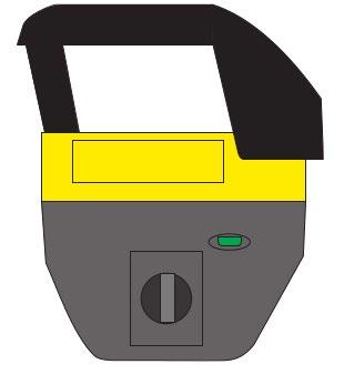
2.4 Emergency Stop
The trailer has 2 emergency stop buttons (E-stop) that perform different tasks depending on which e-stop button is actuated.
1. At the main enclosure (shown in picture).
2. On the remote (shown 2.4.1)
The E-stop at the main enclosure is a master off button. The motor will stop and the computer ECU’s are powered down. The powerpack will crank over and try to restart but will not run.
Resetting the E-stop will allow the powerpack to re-start and the trailer to operate.
Note: some trailers are specified with additional E-stops on the body of the trailer that perform the same function as the main enclosure E-stop.
2.4.1 E-stop/GSS on the Remote Control
Remote control E-stop is actually a; General Safety Stop switch.
The GSS on the remote control shuts down all transmissions from the remote.
If the GSS is pressed on the remote It does NOT turn the powerpack off, the remote will have to be re-synced after the GSS is reset.
The GSS should be used by the operator when he requires the remote to be shutdown for a few hrs when traveling or when not in use.
2.5
Handling Substances
What substances are harmful to the environment?
When you carry out maintenance work on the trailer, you will work with consumables which are classed as harmful to the environment by current national and regional regulations. These include but not limited to - oils, fuel, grease, used oil and fuel filters, as well as rags which have come in contact with these environmentally harmful substances.
When handling these substances follow all regulations as well as the instructions in this chapter.
Use suitable equipment
Substances harmful to the environment can be corrosive. When conducting maintenance work involving these consumables such as oils, coolant and fuel always use containers, hoses, pumps, funnels etc. which are large enough and resistant to the consumables. For oil sampling, always use containers that can be sealed, have adequate capacity, and are resistant to the consumables.
Filling and draining
• When filling and draining, make sure that all harmful substances are collected into containers. Ensure none are spilt in/onto the ground, sewers, drains or water tables.
• Catch consumables (oils, fuels, coolant) in suitable containers when draining.
• Always use a hose and funnel when draining, and funnel or a filling pump with suitable hose for the particular substance when filling.
Collect and store separately
Harmful Substances should always be collected separately from other waste.
• Ask your local environmental protection authority about categorising consumables/ substances.
• Also, when collecting environmentally harmful substances, keep solid materials such as filters separate from liquids. Disposal costs will be reduced if you collect liquids separately according to certain categories.
• Store harmful substances in approved containers and in locations which meet the requirements of current national and regional regulations.
Disposal
Ask your local environmental protection authority about disposal options.
Once accumulated, have the harmful substances disposed of only by approved disposal companies.
When handling diesel and oil around a hot motor, be aware that the products can self ignite on hot surfaces.
2.6 Welding
Please read and understand the following cautions.
Major components of this trailer are made from high tensile steel, PREHEATING BEFORE WELDING is essential to avoid post weld cracking.
Please contact TRT for welding procedures and consumable specifications before welding.
Failure to contact TRT to gain the proper weld procedure could cause additional failures and may result in the warranty being voided.
The batteries MUST be disconnected on both the trailer and the tractor unit. The Isolator on the electrical enclosure must be turned OFF before welding.
Failure to disconnect the batteries and Isolate electronics could cause electronic component failure and / or software corruption.
2.7 Water Blasting
Do not power wash any delicate areas that could be damaged. These could be electrical enclosures, connections and brake valves. Do not have the water blaster nozzle closer than 1 meter from any electrical connection.
When pressure washing avoid all delicate areas especially:
Electrical Enclosures and plug connections.
Hydraulic Valves - located centrally (under the decks) down length of trailer configuration.
3. General Description
The ESS platform trailer is designed to operate trouble free for a specialised application, and be simple to use once the basic training has been undertaken.
It is essential that the operators have the necessary knowledge to operate this specific type of trailer.
3.1 Platform Trailer Features
Each trailer comes with the following standard features:
The trailer is powered by its own electric start diesel hydraulic powerpack.
The trailer will steer automatically, it also has a remote control to steer the trailer. An ESS display unit inside the tractor unit displays information to the driver.
One double acting hydraulic ram at front to lower or raise the gooseneck.
Independent double acting suspension rams, which are fully compensating in suspension mode. (Each side compensates separately).
The gooseneck compensates over uneven roads.
The trailer widens as required.
On each side of gooseneck there are manual drop down landing legs, supporting trailer when disconnected from the tractor unit.
The landing legs are not designed to be used loaded.
Never leave a loaded trailer in a raised position for extended periods. Always fully lower a loaded trailer when not in use. If this is not possible, suitably jack or block trailer and load.
3.2 Steering Overview
1. As the truck turns a corner, an encoder turns inside the rotating skid-plate to indicate the angle of turn.
2. The Electronic Control Unit (ECU) tells the valves to release oil to the steer rams to turn the steering on all axles, commanding them to steer in the correct direction.
3. Linear transducers inside the steer rams indicate the length of ram extension for each individual ram and the ECU calculates each wheel’s steer angle, based on its ram extension.
4. The ECU then calculates the angle the steering should be at and adjusts the rams to suit.
5. The ECU compares the actual information against the theoretical requirements and decides whether the system is working as designed or whether a fault needs to be indicated. (all this happens 100s of times a second).
6. A redundancy system is part of the system design.
4. Inspection & Transportation
4.1 Pre-Operational Checks
On each occasion prior to using the platform the following procedures must be carried out to ensure the safety of the personnel involved.
1. Check that the trailer is road worthy and legal paperwork is current.
2. Ensure that the maintenance schedule is up to date.
3. Walk around the trailer to check for obvious faults such as:
Tyres are all correctly inflated including the spares.
Wheel nuts and studs are torqued to correct tension with none missing (section 7).
No air leaks from hoses, tanks, valves or couplings.
No hydraulic leaks from rams, hoses or valves.
No structural cracks to chassis.
Ensure.
1. AES tank valve is open and drain is closed.
2. The support legs are raised and locked before moving the trailer.
Wheel alignment is correct - to do this the truck and trailer need to be configured in the straight ahead position with wheels straight (powerpack on - section 5).
Check that the trailer kingpin is the correct size and is fully engaged with the 5th wheel.
Ensure the skid-plate drive ‘wedge’ is fully engaged in the 5th wheel.
ALL OF THE HYDRAULIC, ELECTRIC AND AIR COUPLINGS ARE FITTED CORRECTLY.
Test that the brakes and lights are fully operational.
Ensure that load securing devices that will be required are available. This means dunnage and matting - stow securely to prevent movement whilst in transit.
Check that you have the required permits.
Check that the suspension is set to the
correct height and that enough axles are fully compensating for the load that is to be carried.
Check that the route has adequate ground clearance to suit the trailer. This is particularly important over railway lines and off road situations.
Allow for road traction which is significantly reduced in wet or unsealed conditions.
Be aware of weather conditions as these can affect the task to be carried out. Rain and fog can reduce traction, increase stopping times and reduce visibility. High winds will affect the stability of the load. Hot conditions will increase tyre pressures and heat build-up within the axles.
Ensure the powerpack are checked and fuelled. (See specification manual for motor data.)
Check that electrical looms have no chaff damage. Repair any faults immediately. Check that the Turning and/or lifting motion of the trailer cannot pull on the looms.
DANGER
Ensure no personal are under the trailer before starting the powerpack. Failure to do so could result in serious harm or death.
The powerpack ignition must be turned OFF when attaching or detaching the electrical connectors to the truck and trailer. Electrical spikes can occur which can corrupt the software.
4.2 Checking Suspension Bush Wear
Areas of wear that need monitoring on the suspension leg is the bushes in the suspension ram eyes. The axle pivot bushes and the steering ‘king-pin’.
The wear points below should be checked every 5000km
To check the wear:
1. Lock ALL suspension rams
2. Open 1 suspension ram lock valve
3. Using the remote (revs OFF) lower then raise the leg, taking the weight off it and putting a little weight back onto it.
4. Observe the ram for movement within the eyes. Allowable tolerance is less than 1mm.
Check Weekly
5. While checking the eye-bush float, the kingpin end float should also be checked.
Allowable tolerance is 0.2mm to 0.7mm When being assembled and up to 1mm in use.
Check Suspension ram Eye Bush (Top and Bottom) 1.5mm Max
Check Axle Pivot bush wear 1mm max
Check Wheel Bearing play
Check Wheel bearing grease condition
Grease Re-pack Wheel bearings
Check Check Brake Shoe wear
Check Check S-cam bush wear
Check Batteries - Terminal Clamps
Check Batteries - Load test Engine Battery
Check Accumulator Pre-charge - AES
Check Accumulator Pre-charge - Gooseneck
Check Wheel Alignment
Check Tyre Wear
Check Brake drum wear
Normal service requirement
One-off requirement
Check Fuel Level
Check Coolant
Check Operation of Lights
Grease Auto-greaser srease level (Optional)
Replace Hydraulic Filters
Replace Engine Oil
Replace Engine Oil and Fuel Filters
Replace Engine Air Filters
Clean Engine Air Filters (replace if very dirty)
Check Alternator Belt
Check Intake and Exhaust valve clearance
Check Radiator Mounts
Grease Nipples at coaming rail
EP2 Grease
EP2 Grease
Grease Steer Kingpin SBX2
Grease Skidplate MoS2
Check Steer Kingpin End-float 1mm max
Adjust Brakes
Check Wheel-nut torque
Check Tyre Pressures
Check Suspension ram Eye Bush (Top and Bottom) 1.5mm Max
Check Axle Pivot bush wear 1mm max
Check Wheel Bearing play
Check Wheel bearing grease condition
Grease Re-pack Wheel bearings
Check Check Brake Shoe wear
Check Check S-cam bush wear
Check Batteries - Terminal Clamps
Check Batteries - Load test Engine Battery
Check Accumulator Pre-charge - AES
Check Accumulator Pre-charge - Gooseneck
Check Wheel Alignment
Check Tyre Wear
Check Brake drum wear
Normal service requirement
One-off requirement
Check Fuel Level
Check Coolant
Check Operation of Lights
Grease Auto-greaser srease level (Optional)
Replace Hydraulic Filters
Replace Engine Oil
Replace Engine Oil and Fuel Filters
Replace Engine Air Filters
Clean Engine Air Filters (replace if very dirty)
Check Alternator Belt
Check Intake and Exhaust valve clearance
Check Radiator Mounts
Grease Nipples at coaming rail
Grease Steer Kingpin
Grease Skidplate
Check Steer Kingpin End-float 1mm max
Adjust Brakes
Check Wheel-nut torque
Check Tyre Pressures
Check Suspension ram Eye Bush (Top and Bottom) 1.5mm Max
Check Axle Pivot bush wear 1mm max
Check Wheel Bearing play
Check Wheel bearing grease condition
Grease Re-pack Wheel bearings
Check Check Brake Shoe wear
Check Check S-cam bush wear
Check Batteries - Terminal Clamps
Check Batteries - Load test Engine Battery
Check Accumulator Pre-charge - AES
Check Accumulator Pre-charge - Gooseneck
Check Wheel Alignment
Check Tyre Wear
Check Brake drum wear
EP2 Grease
EP2 Grease
6. Operating Instructions
6.1 Starting the ESS Trailer
DANGER
Ensure no personal are under the trailer before starting the powerpack. Failure to do so could result in serious harm or death.
1. Ensure the Accumulator Emergency System (AES) drain valve is in the closed position.
2. Turn the main red isolator to the ‘on’ position (located at the main electrical enclosure).
3. Turn the key to the start position to start the powerpack (located at the main electrical enclosure).
4. Configure the trailer as necessary on the ESS display by confirming the trailer number and width.
6.2 Turning the ESS Trailer off
1. Turn the key to the off position
2. Turn the main red isolator to the off position.
3. When Parking the trailer, care needs to be taken to avoid rain entering the exhaust. The Powerpack exhaust has a 90° tip extending outside the power-pack cover to avoid most of the rain but in an additional cover may be required when the trailer is turned off and the rain is ‘driving’ or swirling in the wind.
Failure to take precautions can result in water ingress into the cylinder(s) and the motor ‘Hydraulicing’ causing serious damage to the motor.
There is an emergency stop button located on the main electrical enclosure, in the event of emergency press this switch.
NOTE:
If the main E-stop is activated on the enclosure the engine can crank and will fire while cranking but NOT continue to run.
6.3 Manual Control
Platform trailers are supplied with a tethered CAN remote instead of a bank of switches inside the enclosure. After plugging the remotes cable in its layout and function is identical to the radio remote. It is plugged in to a socket at the main enclosure and, in the case of trailers with ‘split mode’ (Bridge beam trailers), the remote also plugs into a Module.
6.4 Remote Control
6.4.1 Remote Control Overview
Features on this trailer can be operated by a remote control, this is ideal for use by a third party such as a trailing pilot for increased trailer manoeuvring capability.
Please note the following:
The remote control needs to be paired to the trailer on each start-up for the remote control to become operational.
The remote control does not have a ‘sleep’ mode, it needs to be turned off when not in use.
Controls labelled ‘left’ or ‘right’ on the remote control correspond to the true left and right hand side of the trailer regardless of orientation.
6.4.2 Button Layout
The remote is supplied with 2 batteries and an in-vehicle battery charger.
Turn remote OFF after use to save batteries and avoid accidental actuation of functions.
The green ‘heart-beat’ LED flashes fast when disconnected and SLOW when the remote is connected.
A blinking red LED signals the battery is flat and there will also be an audible beep.
Button Numbers
1. Battery LED (red) and Heartbeat LED (Green) When the green LED is flashing fast the remote is ON but not paired with the trailer. The red light shows a fault like Low battery or incorrect remote set-up hindering pairing (E-stop on)
2. E-stop Button. This only stops the remote and also turns the remote OFF. To turn the remote ON again…. Twist the E-stop and allow it to pop up, then push button 11 to turn the remote on. Pushing button 11 again pairs the remote
3. If the ignition is on and the remote is paired switch 3 will start and stop the powerpack
4. Revs LOW – OFF – HIGH. The low revs is approx. 1800rpm and the high rev setting is 2400rpm. Off is engine idling
5. Steer Auto – Manual. In Auto-steer the trailer steering is controlled by the encoders in the kingpin slew ring.
Manual steering has the remote controller controlling the steer angles. In auto steer the remote can also be used to some degrees of steering correction
6. Steer Left and Right paddle
7. Left suspension Up and Down
8. Right suspension Up and Down
9. Gooseneck Raise Lower
10. Remote and ID key
11. Enable button
12. Widening toggles
13. Ramps raise Lower
14. Ramps Float
15. Winch In and Out
16. Individual axle steer isolation
17. Horn Button
*Actual remote functions and button locations may vary from trailer to trailer. Contact Manufacturer if unsure.
6.4.3 Pairing the Remote
Check that the axles Lock / Unlock valves are in their required positions. (Refer to section 5.9.2)
Turn the powerpack on.
Turn the remote on by de-activating the E-stop (leave the key in the ON position)
Push the green button to connect to the trailer.
If the remote control is turned on but not connected the green LED is flashing fast (1).
If a connection has been established between the trailer and the remote the LED will be flashing slowly - if fast, no connection (1).
Use the emergency stop (2) to turn off every function on remote control. immediately.
Use RPM (3) to switch powerpack from low to high RPM. Ensure it’s switched to high RPM when using more than 5 lines or hydraulic intensive operations such as crab.
Change battery (16) when flat.
6.4.4 Turning the Remote off
1. Activate the E-stop button.
2. Ensure that the steering switch is in the auto position.
6.4.5 Replacing & Charging the Battery
1. The battery is located on the rear of the remote control.
2. Place your finger in the tab and pull the battery out.
3. Slide the replacement battery in and then press down.
4. Place the removed battery on charge using the supplied charger.
DANGER
Ensure no personnel are under the ramps before enabling ramp float. Ramps should be kept clear at all times. FAILURE TO DO SO COULD RESULT IN SERIOUS HARM OR DEATH.
Remote layouts vary from trailer to trailer depending on options selected. NOTE:
NOTE:
The ESS display unit is default i.e. if the trailer powerpack is set to the off position the powerpack will default to the ESS display unit setting.
6.5 Powerpack
6.5.1 Powerpack Overview
The powerpack is a diesel engine fitted with a hydraulic pump assembly. Located at the front of the gooseneck. It is responsible for maintaining hydraulic pressure and powering the electrical system while the trailer is in operation.
6.5.2 Powerpack RPM Adjustment
The powerpack RPM lifter requires air pressure to operate and has a control switch with 3 modes (option dependant) it can be controlled by a switch at the manual control station inside the enclosure, the ESS display unit in the cab, or the switch on the remote.
The powerpack has 3 RPM stages:
OFF - Powerpack remains at Idle.
LOW - Engine runs at raised RPM (Approx. 1900rpm).
Recommended when using configurations in conditions that require normal hydraulic duties (suspension operation, widening, or when using other steering modes such as crab auto).
HIGH - Engine runs at elevated RPM (Approx. 2400 rpm).
Recommended when using configurations in conditions that require faster hydraulic duties (suspension operation, widening, travelling around tight areas using normal auto steer or when using other steering modes such as crab auto).
The RPM can be lifted using the remote.
(Low – OFF – High).
Trailer control ESS display unit inside truck.
Revs tabs on travel screen.
Ensure the powerpack RPM is above idle before travelling on any road.
DANGER
Ensure the powerpack is switched off, disabled and the cabinet is locked when personnel are under the trailer. FAILURE TO DO SO COULD RESULT IN SERIOUS HARM OR DEATH.
The powerpack ignition must be turned OFF when attaching or detaching the electrical connectors to the truck and trailer. Spikes can occur which can corrupt the software.
NOTE:
NOTE:
The powerpack is fitted with a horn to warn the driver if a critical fault occurs. This with the AES allows the driver to safely pull over to address the issue.
The ESS display unit in the truck receives ALL its data and electrical supply from the trailer. Turning the trailer ignition ON will start the ESS display unit.
6.6 AES (Accumulator Emergency Steer)
6.6.1
AES Overview
The accumulator emergency steer system (AES) is a redundancy system. In the event a major issue is detected, an alarm is activated and it pressurises the main hydraulic lines for a short amount of time (approx. 6 seconds) in which time the driver must pull over.
The AES system is fitted with a hydraulic accumulator tank combined with a solenoid valve. When the powerpack is first turned on the AES solenoid valve is deactivated in a free flow in and free flow out state.
The pump runs at maximum load allowing the accumulator to build pressure. Once at the designated pressure the AES solenoid activates a free flow in and checked flow out state. This holds the accumulator at the designated pressure whilst the pump and main hydraulic line drop to a normal operating pressure.
If the main controller detects that the powerpack has stopped running, stopped charging, lost engine oil pressure, or that the pump is not operating at the correct pressure an alarm will sound and be visible on the ESS display. The AES solenoid valve deactivates into a free flow in and free flow out state providing the main hydraulic lines with supplementary pressure. This in turn allows the trailer to steer for approximately 6 seconds, in which time the driver must pull over.
The AES accumulator will give approximately 6 seconds of emergency steering pressure to allow the trailer to pull off the road. NOTE:
6.6.2 Daily Inspections
De-pressurising the AES system
An accumulator drain valve is located on the goose-neck. opening the valve will drain the accumulator pressure back into the tank
You must drain the AES system in the following scenarios:
1. Before personnel can work underneath the trailer or nearby any hydraulic componentry.
2. Before attaching or removing any hydraulic connections. (necessary for attaching and detaching clip-ons.)
3. Hydraulicly coupling a Dolly to the front couplings
The AES pressure release valve will vary in position from trailer to trailer.
NOTE:
6.6.3 Testing the AES system
Whenever the powerpack is serviced we recommend that the AES system is tested to ensure it’s operating correctly.
1. Start the powerpack and ESS electronics (section 5).
2. Check that the AES pressure is approx 280 bar and the main pressure is approx 280 bar on the ESS display unit.
3. Toggle the AES system test switch to the on position in the main electrical enclosure, this will shut the powerpack down
4. Check that the AES pressure and main pressure match and are slowly dropping from approx 280bar on the ESS display unit.
5. Move the AES drain valve to the open position slowly and audibly confirm that the pressure has depleted.
6. Toggle the AES system test switch to the off position in the main electrical enclosure.
7. Move the AES drain valve to the closed position.
8. Start the powerpack and ESS electronics (section 5).
9. Check that the AES pressure is approx 270 bar and the main pressure is approx 280 bar on the ESS display unit.
6.7 Gooseneck
6.7.1
Gooseneck Overview
The gooseneck hydraulic cylinder that allows the trailer to compensate for irregular terrain, supplementing the trailers suspension; it also acts as a shock absorber for things such as potholes.
In further detail, the gooseneck cylinder is a double acting hydraulic cylinder that has a large accumulator plumbed into the load holding circuit.
As the load on the kingpin increases the accumulator absorbs oil allowing the cylinder to close and the kingpin to rise (front of the trailer lowers).
As the load on the kingpin decreases the accumulator returns oil allowing the cylinder to open and the kingpin to lower (front of the trailer rises).
When the load returns to a neutral state, the cylinder will return the kingpin to neutral ride height.
The accumulator is pre-charged to operate with the trailer carrying a road legal load as would be expected in normal operating conditions.
6.7.2 Gooseneck Lock Valve
NOTE:
NOTE:
The accumulator will be less effective if the trailer is overloaded and being driven off-road, or if the trailer is empty or lightly loaded.
The screen in the truck cab receives ALL its data and electrical supply from the trailer. Turning the trailer ignition ON will start the screen.
The gooseneck cylinder features a manual lock valve, when locked the gooseneck will no longer compensate and will remain in its current position.
This is useful for the following situations:
Holding the gooseneck still when decoupling (section 6), so that the gooseneck doesn’t drop when the truck drives away.
Holding the gooseneck low (kingpin high) when coupling, so that truck can be easily positioned in-line with the kingpin without the trailer loading the truck, and then raising the gooseneck (kingpin lower) once lined up.
1. Gooseneck cylinder valve locked - position 1.
Ensure ALL suspension isolation valves are in travel mode when operating the gooseneck ram. Excessive loading to be implied on any locked suspension rams
NOTE:
When the prime mover is removed from the trailer the skid-plate needs to be locked from falling, if the skid plate needs to be locked from falling. If the skid-plate is too low, raise the skid-plate by starting the powerpack and operating the gooseneck down.
The powerpack ignition must be turned OFF when attaching or detaching the electrical connectors to the truck and trailer. Spikes can occur which can corruptthe software
Fig.
6.7.3 Lowering the Gooseneck
1. Ensure the powerpack and ESS electronics are running (section 5).
2. Ensure the gooseneck lock valve is in travel mode
3. Hold the gooseneck switch in the lower
Example
Control valve has raised trailer to ride height.
6.7.4 Raising the Gooseneck
1. Ensure the powerpack and ESS electronics are running (section 5).
2. Ensure the Gooseneck lock valve is in travel mode.
3. Hold the Gooseneck switch in the raise position.
NOTE:
If the trailer has been lowered onto blocks or a load has caused the trailer to ‘bow down’ at the front, it may take a while for the gooseneck cylinder to start extending, due to the accumulator being filled first.
6.8 Suspension
6.8.1
Suspension Overview
The suspension on this trailer consists of independent double acting hydraulic cylinders fitted to each axle. These cylinders are set-up to be fully compensating down the length of the trailer, compensating separately on each side of the trailer. They are also used for raising and lowering the ride height of the trailer for loading purposes as well as various general transport scenarios. They are also capable of lifting individual axles off the ground if necessary. In the circuits between the Suspension Control valve and the Suspension lock valves there is a counterbalance (load Hold) valve fitted.
6.8.2 Suspension Lock Valves
Each suspension cylinder can be manually locked for varying purposes, individual axles can be lifted off the ground if necessary by using the suspension locks in conjunction with the suspension ride height controls.
Each suspension lock is located in front of the appropriate axle on the inside of the coaming rail and can be manipulated as follows:
Up / Horizontal - Locked Position
Down / Vertical - Travel Mode
6.8.3 Raising the Trailer
1. Check that the suspension lock valves are in the Travel Mode position.
2. Ensure the powerpack is running (section 5).
3. Operate the suspension controls by moving the LH side and RH side joysticks in the raise position. (Manipulate the controls so that the trailer rises evenly and remains level.)
4. Adjust the gooseneck to suit the ride height.
5. Ensure all appropriate axles remain in contact with the ground, manipulate suspension and gooseneck controls as necessary.
6.8.4 Lowering the Trailer
1. Check that the suspension lock valves are in the Travel Mode position.
2. Ensure the powerpack is running (section 5).
3. Operate the suspension controls by moving the LH and RH side suspension switches or joysticks in the lower position. (Manipulate the controls so that the trailer rises evenly and remains level.)
4. Adjust gooseneck to suit ride height.
NOTE:
Ensure no personnel are under the trailer before starting the powerpack.
Failure to do so could result in serious harm or death.
Never leave a loaded trailer in a raised position for extended periods. Always fully lower a loaded trailer when not in use. If this is not possible, suitably jack or block trailer and load.
The suspension must always be put in the Travel Mode before moving or ESS trailer damage may result.
DANGER
6.8.5 Ride Height Examples
6.8.5.1 Ride Height too High
The oil cannot transfer from the compressing cylinder as it travels over the hump. This is due to no stroke being left in the cylinder that the oil is trying to transfer into.
The cylinders are extended too far with too much oil to transfer.
The wheels remain off the ground due to no travel being left in the cylinders.
Direction of travel
In the example shown the load is taken on the first axle with no load sharing on the others - the trailer could ‘break its back’.
6.8.5.2
Ride Height too Low
The oil cannot transfer from the compressed cylinder as it travels over the hump. This is due to no stroke being left in the cylinder that the oil is trying to transfer from.
The cylinders are not extended enough to allow oil to transfer.
The wheels remain off the ground due to no travel being left in the cylinders.
In the example shown the load is taken on the first axle with no load sharing on the others - the trailer could ‘break its back’.
Direction of travel
6.8.5.3
Ride Height Correct
Oil is able to transfer from cylinder to cylinder as suspension travels over rough terrain. If a wheel runs over a hump the oil is able to transfer from the cylinder into the other cylinders that have stroke (travel or volume) left to accept the oil.
Oil movement is shown by the arrows.
of travel
Direction
6.8.6 Lifting Individual Axles
1. Ensure the suspension lock valves are in the locked position for every axle you want to remain on the ground.
2. Ensure the suspension lock valves are in the unlocked position for every axle you want to lift off the ground.
3. Ensure the powerpack is running (section 5).
4. Operate the suspension controls by moving the LH and RH side suspension switches or joysticks in the lower position until the axles are suitably off the ground .
5. Change the suspension lock valves to the lock position for all axles that have been lifted off the ground.
6. Change the suspension lock valves to the unlock position for all axles that remain in contact with the ground.
7. Gen4 has the option of isolating the steering from operating when an axle is raised. If the power is cycled the axle returns to its steer active mode. More information on this function is available under STEERING in this manual
Never lift 2 axles on a side when loaded or travelling.
Avoid having them hard up against the deck as they will still attempt to steer during normal operation. NOTE:
Direction of travel
Axle lifted and locked
Axle lifted and locked
6.9 Widening
6.9.1
Widening Overview
The overall width of this trailer can be adjusted using hydraulic cylinders in the widening boxes that separate the left and right hand side decks from each other. This increases the trailers capability of carrying loads of various sizes.
6.9.2 Adjusting the Trailer Width
1. Ensure the powerpack and ESS electronics are running (section 5).
2. Set the trailer configuration on the ESS display as well as the desired width.
3. Adjust the front, and rear widening controls until the trailer is at the desired width. (Try to keep the trailer decks even when widening to avoid any binding or damage, this can be done by manipulating the controls as necessary.)
4. Measure the centre and rear width and adjust as necessary to match the front.
WIDENING CONTROLS
5.10 is relating to steering as a platform trailer. When the trailer is configured as a beam trailer there are different control requirements. If Beam trailer mode steering is optioned it will be addressed in an options sections at the rear of the manual.
6.10 Steering
6.10.1 Steering Overview
This trailer features an electronic steering system (ESS). All the axles are connected to hydraulic cylinders which are controlled by electronic controllers within the trailers electrical system. The ESS display unit and remote control provide the ability to change between various steering modes that allow for increased manoeuvrability whilst providing an extended tyre life due to minimising scrub.
The electronic steering system (ESS) comprises of the following main components:
1. Turntable encoders
These are rotary encoders inside the kingpin turntable assembly, they are responsible for communicating the current steering angle of the truck at the kingpin to the steering controller.
2. Steering position transducers
These are position transducers within the hydraulic steering cylinders, they are responsible for outputting the current steering angle to the steering controller.
3. Powerpack
This is a hydraulic pump driven by a diesel engine. It is responsible for supplying hydraulic pressure to all the hydraulic components fitted to the trailer.
4. Steering controller and screen
This is a programmable logic controller that’s responsible for receiving input from all the related sensors and controlling the output signal to each steering cylinder. During operation it also checks to confirm everything is operating as intended. In the event a fault occurs it will record and display
an alarm on the ESS display unit.
5. Hydraulic steering cylinders
These are hydraulic cylinders directly connected to each axle and are responsible for controlling the steering angle of each axle.
6. A CANBUS wiring system
The digital information relating to the encoder angles, steer ram transponder length, radio and tethered remotes has to travel very fast to the ECU’s Information is also carried by CANBUS to the screen in the
NOTE - General wiring
It is important that all wiring and plugs be kept in good condition, water blasting plugs and connectors can force water into connections which will degrade their connectivity.
Crush hazard.
Steering may turn automatically keep clear of tyres at all times when motor is running or electronics on.
The powerpack must be running when traveling. The trailer will not steer unless its running.
The main suspension king-pin requires Castrol SBX2 grease (see section 7.2.4). Failure to use this grease, or mixing in a different grease, will significantly increase the resistance in the steering system.
Do not use Castrol SBX2 grease in other areas of the trailer. The graphite grease will lock up the distributor manifolds.
At low RPM the steering may be delayed or may not operate as intended in intensive hydraulic use.
DANGER
6.10.2 Steering Modes
6.10.2.1 Normal Auto Steer (Fully Automated)
Normal auto steer is useful for day to day operation as it provides excellent manoeuvrability around tight corners and narrow roads. It also extends tyre life due to minimal scrubbing.
Normal auto steer is the default steering mode selected when the ESS electronics are first powered on. When normal auto steer is selected a theoretical ‘pivot point’ is calculated based on a pre-determined ‘pivot length’* and the current turntable angle detected by the turntable encoders. As the truck is turning, all the axles on the trailer will turn to the correct steering angle to follow an arc around the theoretical pivot point. Normal auto steer can be selected at any time using the ESS display unit. (Unless the remote control is set to manual steering).
Pivot Line Pivot Point
6.10.2.2 Normal Auto Steer (Plus Remote Control Input)
When normal auto steer is selected, the remote control can be used to make live temporary adjustments to the trailers steering trajectory, this can be useful for situations where there may be hazards on either side of the trailer whilst cornering.
For this function to operate the following requirements must be met:
The steering mode on ESS Display Unit is set to normal auto steer.
The remote control is powered on and paired to the trailer.
The remote control steering switch is set to AUTO
The trailer is currently steering.
When these requirements are met, the remote control steer joystick can be moved to either side while the trailer is steering, this temporarily adjusts the ‘pivot length’ of the trailer and causes the trailer to respond by moving in the commanded direction. Due to how the pivot point is calculated, the remote control will have no effect on steering when the trailer is travelling straight.
Example:
1. During a left hand turn
If the remote control steer joystick was held to the left, the trailer would move to the left and ‘cut’ into the corner.
If the remote control steer joystick was held to the right, the trailer would move to the right and swing wide.
2. During a right hand turn
If the remote control steer joystick was held to the left, the trailer would move to the left and swing wide. Fig. 1.
If the remote control steer joystick was held to the right, the trailer would move to the right and ‘cut’ into the corner. Fig. 2.
3. Whilst travelling straight
If the remote control steer joystick was held to the left, the trailer would continue to travel straight.
If the remote control steer joystick was held to the right, the trailer would continue to travel straight.
Fig. 2.
Steering
Steering in Auto Mode
Fig. 1.
6.10.2.3
Crab Auto
Crab auto is useful for manoeuvring the trailer within yards for loading, unloading, and trailer configuration.
When crab auto is selected all axles will turn and match the angle detected by the turntable encoders.
As the truck turns to either side, the trailer will remain facing the same direction but will ‘crabwalk’ sideways behind the truck.
Crab auto can be selected at any time using the ESS display unit. (Unless the remote control is set to manual steering)
6.10.2.4 Crab Manual
Crab manual is useful for manoeuvring the trailer within yards where visibility or space may be limited, or where precision is required.
When crab manual is selected, the remote control will override the drivers steering input and the axles will all turn to face straight ahead, operating the remote control steer joystick will turn the rearmost axles, and all axles in front will follow suit in a staggered manner. When the remote control steering joystick is released, the axles will maintain their current angle.
This causes the trailer to rotate around the kingpin when the truck and trailer are in motion.
Once the angle detected by the turntable encoders matches the steering angle of the rearmost axles, the remaining axles will turn to match the rearmost axles steering angle (i.e. no longer staggered) and the trailer will continue to crab walk at the current angle.
Crab manual is selected when the following conditions are met:
The remote control is powered on and paired to the trailer.
The remote control steering switch is set to MANUAL.
In summary:
1. Crab manual is selected and the trailer axles turn straight ahead.
2. The remote control joystick sets rearmost axles to a user controlled angle, all other axles follow suit in a staggered manner.
3. The trailer rotates around the kingpin when in motion.
4. Once the turntable encoder angle matches the rearmost axles steering angle, the remaining axles turn to match the rearmost axles steering angle and the trailer continues to crab walk at the current angle.
2 1 3 4
6.10.2.5 Rear Axle Straight
Rear axle straight can be useful for situations where the driver may prefer a more traditional trailer such as reversing.
When rear axle straight is selected, it modifies the configured pivot length and causes the rearmost axles to turn and point straight ahead and all other remaining axles to turn in the same direction as the truck in a staggered manner.
As the truck is turning, the trailer will respond much like a traditional trailer and have significant ‘cut in’ whilst still minimising tyre scrub.
Rear axle straight can be selected at any time using the ESS display unit. (Unless the remote
Pivot Line
Pivot Point
6.11 ESS Display Unit
6.11.1
ESS Display Unit Overview
The ESS display unit is the main control that will be used for day to day operation of the ESS trailer, it is used for setting the trailer configuration, widening, steering modes and powerpack RPM adjustment.
It is also capable of being used for roadside diagnostics. It communicates any alarms to the driver and can display in-depth information on the state of various sensors and electronic components of the trailer.
6.11.2 Button Layout
The ESS display unit includes 12 physical buttons on the left and right sides that are used to operate the various functions of the system.
6.11.2.1
Quick Screen Reference
Truck Screen
The screen in the truck configures the trailer for daily operation, controls some of the trailer functions gives feedback on the status of the trailer and its ‘health’ for operation
Screen Power:
The screen is powered from the trailer. Both ether ignition and the 24v isolator must be on for the screen to turn on
On the back of the screen is a ‘square’ plugging point that receives the Power, Earth and CAN
If the screen boots up but a banner appears saying:
“NO COMMUNICATION WITH CONTROLLERS”
the CAN wires should be checked in both the Cab Looms, The Plugs, and the wiring to the enclosure.
The screen will turn on as soon as the power is turned on at the Power-pack. Then the screen first ‘boots up’ you will see a ‘splash screen then the ‘Configuration screen’
6.11.2.1 Quick Screen Reference / Guides
6.11.2.1 Quick Screen Reference / Guides
6.11.2.1 Quick Screen Reference / Guides
6.11.2.1 Quick Screen Reference / Guides
6.11.3 Screen Colour Scheme
Light blue buttons
Light blue buttons are used for navigation to different views. These can be pressed either on screen or with their corresponding physical buttons on the unit.
Light grey buttons
The light grey buttons on the travel page are used to change the steering modes. These buttons will not respond to touch commands and can only be enabled by pressing the physical buttons on the side of the ESS display unit. This is to reduce the risk of accidentally changing the steering mode.
Whe a red ring appears around a function button it indicates that the button has been locked out on the ‘over-speed speed’ Programming. This stops accidental operation of a function that could drive the trailer off the road
Light grey buttons are also used for selecting functions. E.g. selecting which encoder to calibrate or which part of the trailer to raise or lower. These buttons are buttons in the middle of the display and are not linked to any physical buttons. Therefore, these can be operated by touch commands.
Fault indicators
Fault indicators (where applicable) are given in red. If no faults are detected the indicator is green.
6.11.4 Configuration
The configuration page is the main boot up page. The operator is required to enter the appropriate configuration for the trailer setup currently being utilised. Trailer configuration and widening width can be selected from the drop-down list. After setting up the trailer configuration, press the SET CONFIG button. If the configuration has been set successfully, the LED will turn GREEN as shown in the image above.
Care must be taken to enter the correct configuration as errors in this selection may cause catastrophic failure of the steering and auxiliary systems.
6.11.4.1 Alarm Banners
A “No communication with the controllers” message will display if the main screen cannot detect the heartbeat signal from the controllers. Please check if the CANBUS communication cable from the controllers to the main screen is damaged or plugged incorrectly.
A critical steering fault may occur due to the following reason:
If more than two position transducer faults occur.
There is a fault in calculating the encoder positions.
Fault in the encoders.
Remote control voltage too low.
Hydraulic pressure under 5 bar.
6.11.5 Travel
The travel page is the dashboard for the trailer. The operator can change the steering modes and turn ON/OFF the engine hi-idle command. The active steering mode is highlighted in a GREEN background, whilst inactive modes will remain GREY.
From this page the operator can also navigate to the various set up pages to change the settings and configuration in the program, as well as view any active or past alarm events in the alarm manager.
The operator will also be alerted to any faults in the system when the AUXILIARY STATUS and STEERING STATUS icons are changed to a RED background. These faults should be checked and assessed as soon as possible. Pressing these indicators will navigate to the AUXILIARY and AXLE pages.
6.11.5.1 Alarm Banners
This alarm banner pops up if the trailer is in LIMP HOME MODE and forced to use only one encoder. This alarm banner pops up if the operator did not set the trailer configuration in the CONFIGURATION page. Please navigate to the CONFIGURATION page by pressing the SETUP TRAILER button.
6.11.6 Auxiliary Page
This page provides a quick summary of the state of each auxiliary function as well as the status for the controller that controls the modules. GREEN backgrounds and GREEN LEDs indicate a healthy system functioning correctly. LEDs and backgrounds will turn RED when there is a fault or warning associated with the accompanying function. Pressing on any of the functions will navigate to individual auxiliary status view.
The HI VOLT ERROR and LO VOLT ERROR faults are triggered if the voltage to the remote control. controller is above 30V or below 16V respectively.
VSS1 ERROR fault is triggered if the VSS1 sensor voltage generated by the controller is above 5.5V or below 4.5V.
VSS2 ERROR fault is triggered if the VSS2 sensor voltage generated by the controller is above 10.5V or below 9.5V.
6.11.6.1
Auxiliary - Widening
If no fault is detected, indicator will be GREEN. If a fault is detected in any of the coils (E.g. due to wire damage or short circuit to ground or power) the respective coil indicator will turn RED. If indicator turns RED, please check if the coil is unplugged or has wire damage.
6.11.6.2 Auxiliary - Gooseneck
If no fault is detected, indicator will be GREEN. If a fault is detected in any of the coils (E.g. due to wire damage or short circuit to ground or power) the respective coil indicator will turn RED. If indicator turns RED, please check if the coil is unplugged or has wire damage.
6.11.6.3 Auxiliary - Suspension
If no fault is detected, indicator will be GREEN. If a fault is detected in any of the coils (E.g. due to wire damage or short circuit to ground or power) the respective coil indicator will turn RED. If indicator turns RED, please check if the coil is unplugged or has wire damage.
6.11.6.4 Auxiliary - Hydraulic Pressure Unit
This page shows the pressure values for the main hydraulic system and the AES system. The raw voltage signal from both the sensors are shown along with their scaled pressure values.
When the AES system is charging the accumulator, the LED for AES Charging turns GREEN. If the AES system is unable to charge up in a specified time, the LED for AES Timed Out will turns RED and show the warning banner.
If a fault is detected in the AES coil, AES Coil Fault will turn RED. A fault is triggered when the system can’t detect the coil or if the coil has short-circuited to ground or battery. Please check if the coil has been unplugged or has wire damage.
In case of fault with the main hydraulic system, the AES system will discharge pressure and the LED for AES Active will turn RED.
6.11.6.5 Auxiliary - Ramps
AUXILIARY STATUS
21-03-2024 11:23:58
If no fault is detected, indicator will be GREEN. If a fault is detected in any of the coils (E.g. due to wire damage or short circuit to ground or power) the respective coil indicator will turn RED. If indicator turns RED, please check if the coil is unplugged or has wire damage.
6.11.6.6 Auxiliary - Encoder
The ENCODER page, a fault is indicated by a RED LED and healthy operation by a GREEN LED:
The ESS trailers use two encoders at the turntable to calculate the turntable angle. By default, the encoder 1 is used to calculate the angle with the encoder 2 used as a redundancy. When the encoders are calibrated to zero degrees (turntable straight ahead), it sets the encoder count to 20,000.
When the encoder is detected and operating correctly, the STATUS LED turns GREEN. The COMMS LED actively checks the connection of the encoder by monitoring its heartbeat signal. In healthy operation, the COMMS LED is GREEN. If a heartbeat is not detected for a duration of longer than 1 second the COMMS LED turns RED. The ACTIVE LED indicates which encoder is used to
calculate the truck angle.
As there two Encoders in redundancy, in the event where the difference between the two encoders exceed a threshold the Encoder POSN Check LED turns RED. This is done to monitor if an encoder is connected but giving a faulty reading. The ENC POSN Check LED turns GREEN if both the encoders are within the set window.
The system actively verifies the turntable angle by calculating in two methods and checking if they are the same. If any of the parameters for the encoders have changed, e.g. the teeth count, resolution, etc, the angle calculation will be incorrect and the TRUCK ANGLE CALC LED turns RED. If all the parameters for the encoders are correct and encoders are operational, TRUCK ANGLE CALC LED turns GREEN.
The ENC Status LED turns RED if any fault is detected in the encoder’s communication or calculations. If no fault is detected LED turns GREEN.
ENCODERS
ENCODERS
6.11.6.7 Encoder Pairing
Encoder Pairing
The main type of encoders that we are supplied from IFM, but we have sourced a 2nd type of encoder from Wachindorff for our GEN4 trailers that will work as an alternative. The build of the encoder needs to be correct for the trailer to operate, and the encoder needs to be ‘initialised’ before it will work on the trailer.
NOTE: A laptop with BODAS service OR a technician with the TRT PIN number to access the service code in the ECU through the screen is required for initialising a new encoder
Setup Encoders
1.1.1. If using IFM RM9000 encoders, refer to information below to read encoder status. Confirm encoder LED is flashing GREEN. If there is no LED light on the encoder, check encoder power supply
If using Wachendorff encoders refer to information below to read encoder status. Confirm encoder LED is flashing GREEN. If there is no LED light on the encoder, check the power supply
Using A Bodas Equiped Laptop
1.1.2. Axle Test Mode should be turned ON across all connected modules, to ensure axles will not move while setting up encoders.
1.1.3. Once encoders are powered ON and indicator LEDs are blinking, log in to the A-module Steering controller (RC28-14) and proceed to Parameter Group 7.1 Encoders.
1.1.4. Select the make and model of the encoder for Encoder 1 and Encoder 2 using the dropdown lists in Parameter 7.1.4 Encoder 1 Selection and Parameter 7.1.5 Encoder 2 Selection.
1.1.5. Both encoders can be plugged in and initialised at the same time. To Initialise encoders, turn ON parameters on both Parameter 7.1.1 Start Encoders Init and Parameter 7.1.2 Encoder Init Confirm.
1.1.6. After initialising encoders, on the DI4 screen, proceed to the CANBUS SENSORS page. This can be accessed by following the path:
CONFIGURATION >> TRAVEL MODE >> Module 1
AUXILIARY STATUS >> CANBUS SENSORS
1.1.7. If encoders were initialised successfully, the CASE STEP for both encoders will show “90”.
1.1.8. Once initialised successfully, the following message will prompt at the bottom left corner to cycle power:
1.1.9. Cycle power on the trailer and check LED of the encoder. LED should now be flashing green at 2.5 Hz.
6.11.6.7 Encoder Pairing
1.1.10. To confirm both encoders have been initialised successfully and communicating properly, check if the following Processdata are as expected:
21-03-2024 11:23:58
1.1.11. Select which encoder is to be calibrated. Selected encoder becomes green.
1.1.12. Press START CALIBRATION to start the calibration process.
1.1.13. When calibrated successfully, the Encoder Count on the right side will show 20,000 for the calibrated encoder and the following message will show:
1.1.14. Wait for the CALIBRATION COMPLETE message to disappear and CASE STEP to go to 2. Then, repeat for next encoder.
NB: For more details refer to page 61 - 5.11.10
Encoder Calibration
6.11.7 Axle Status
This page provides quick summary of the state of each axle as well as the status for the controller that controls the axles. GREEN backgrounds and GREEN LEDs indicate a healthy system functioning correctly. LEDs and backgrounds will turn RED when there is a fault or warning associated with the accompanying axle. Pressing on any of the axles will navigate to individual axle status view.
HYDRAULIC PRESS STATUS will show a fault if the hydraulic pressure drops below 5 bar.
MOD OK fault can be triggered by any of the following:
Fault with any of the encoders.
STEERING OK fault.
STEERING OK fault can be triggered by any of the following:
Voltage to remote control too low.
E-Stop engaged.
Start-lock error – remote control could not start up due to a fault.
No steering mode has been set.
Hydraulic pressure too low.
STEERING STANDBY is healthy when the wheels are at their target positions. Once a new target position is given for the axles, if they do not reach their target positions within a window of 2 seconds, it triggers a STEERING STANDBY fault.
TRANS FAULT STATUS triggers a fault if more than two position transducers fail. A position transducer fail can occur if the sensor is unplugged or the wire is damaged.
This page shows the coils used by the axles for its steering functions. The operator can view data for other axles by pressing on the required axle tab in the tab navigation.
The coloured bar below each axle in the tab navigation is used to indicate to the operator a fault has been detected in that particular axle. If no faults are detected the bar is GREEN, when a fault is detected the bar turns RED. E.g. in the Fig 1. a fault has been detected in AXLE 3.
Each wheel-set has two coils, one for turning left and one for turning right. If a fault is detected in any of the coils, the indicator will turn RED as shown in Fig 2.
Each individual output coil current is displayed under its respective coil status. These values are in amps and will go up to 0.8A when the coil is fully energised.
The transducer currents next to the POSITION SIGNAL statuses shows the input current from the position transducer in a 4-20 mA range for both LH and RH side wheel-sets. When the wheels are straight, the current sensor reads approximately 12 mA.
Fig 1.
Fig 2.
6.11.8 Setup/Diagnose
The SETUP/DIAGNOSE Page can be accessed by pressing on the SETUP/DIAGNOSE button on the TRAVEL Page.
On this page, the operator can change the ESS display unit brightness, volume levels and date/ time displayed by the main screen.
6.11.9 Limp Home
The LIMP HOME page can be accessed from the Encoder page under Auxiliary Statuses and in the SETUP / DIAGNOSE page.
By default, the encoder 1 is used to calculate the turntable angle with the encoder 2 used for redundancy. If a fault occurs with the encoder 1, it will trigger an alarm and automatically swap the active encoder to encoder 2. The operator can also force the system to use encoder 2 instead of the default encoder 1 at any time by pressing on the Use Encoder 1 button. When the button is pressed, it will turn GREEN as shown in Fig 1: If the encoder changeover is successful, the active encoder LED will switch to ENC 2
The system actively monitors the CANBUS communication lines as well for a fault in the system. If a fault is detected in the CANBUS lines, the messaging will automatically swap over to the secondary CANBUS. The operator can also force the system to communicate on the secondary CANBUS instead of the primary CANBUS by pressing on the CAN Secondary button. When the button is pressed, it will turn GREEN.
Fig 1.
6.11.10 Encoder Calibration
CALIBRATE ROTARY ENCODER
The CALIBRATION page can be accessed from the ENCODER page under Auxiliary Statuses and in the SETUP / DIAGNOSE page.
When the turntable is straight, the encoder count should read 20,000. If the count is different, the system will think the trailer is at an angle and cause the trailer to swing out while driving straight. This can be rectified by calibrating the rotary encoders when the turntable is straight.
To calibrate the encoders, first ensure the turntable is facing dead straight. Next, select which encoder is to be calibrated. When the encoder is selected successfully, it will change colours from LIGHT GREY to GREEN. Fig 1.
When the desired encoder is selected, press on START CALIBRATION button on the ESS display unit. This will prompt a confirmation message as shown. Confirm encoder calibration by pressing the GREEN YES button on the popup. After successfully calibrating the encoders, a message will be displayed at the bottom stating “CALIBRATION COMPLETE”. It will also deselect the encoder and change the encoder count to 20,000.
Fig 1.
6.11.11 Diagnostics
The DIAGNOSTICS page can be accessed by pressing the STEERING DIAGNOSE button on the SETUP / DIAGNOSE page.
This page is intended for diagnosing faults with the steering pivot point. The dimensions shown are for indication only and might differ from the actual values by ±0.5m.
The bar graph on the right shows the load sense valve command that drives the pump pressure.
6.11.12 Alarms
The ALARMS page can be accessed by pressing on the ALARMS buttons on the CONFIGURATION page. This page allows the operator to view all the faults that are logged into the system. All new faults appear in RED text. If the fault becomes healthy, the text colour turns GREEN. The operator can scroll through the alarms in the Alarm Manager by rotating the control knob on the unit. Pressing on the ACK All Visible button
COIL FAULTS
Suspension Left Hand Raise Fault
Suspension Left Hand Lower Fault
Suspension Right Hand Raise Fault
Suspension Right Hand Lower Fault
Gooseneck Raise Fault
Gooseneck Lower Fault
Ramp Raise Fault
Ramp Lower Fault
Ramp Float Fault
Support Leg Raise Fault
Support Leg Lower Fault
Trailer A (if applicable) Pump Prop
Error
will acknowledge all the fixed faults and remove them from the active alarms view. The operator can also choose to acknowledge individual fault codes by selecting the individual fault and pressing on the ACK Selected button. All the faults are saved into the memory. Pressing on the History button will show all saved faults. A description of the alarm messages are given in the tables below.
DESCRIPTION
Fault is triggered when the system cant detect the coil or if the coil has short circuited to ground or battery
RECOMMENDATIONS
Check if the coil has been unplugged or wire damage
STEERING FAULTS
Trailer (B/C) - Axle XX LH A Coil Fault
Trailer (B/C) - Axle XX LH B Coil Fault
Trailer (B/C) - Axle XX RH A Coil Fault
Trailer (B/C) - Axle XX RH B Coil Fault
Trailer (B/C) - Axle XX LH Position Transducer
Fault
Trailer (B/C) - Axle XX RH Position Transducer
Fault
Trailer (B/C) - Axle XX LH Position Check Fault
Trailer (B/C) - Axle XX RH Position Check Fault
Trailer (B/C) - Axle Transducer Error
Trailer (B/C) - Major Steer Fault. Axles not responding
ENCODER FAULTS
Trailer-A - ENC 1 Healthy Error
Trailer-A - ENC 2 Healthy Error
Trailer-A - ENC 1 Comms Error
Trailer-A - ENC 2 Comms Error
DESCRIPTION
XX = Axle #.
Remote control output has detected a fault with the specified coil
Fault occurs if the transducer reading is below 4mA or above 20mA
Indicates the wheelset is not at its target position
Fault is triggered if more than two position transducers fail
Fault can be triggered by any of the following:
Axle Transducers Fault
Error in processing encoder position
Fault in the encoders
Remote control voltage too low
Hydraulic pressure under 5 bar
DESCRIPTION
Encoder fault
Fault is triggered if the remote control is not receiving the encoder heartbeat signal
RECOMMENDATIONS
Check if the coil has been unplugged or wire damage
Check sensor power and if the signal wire is broken
RECOMMENDATIONS
Check the following:
Confirm encoder LEDs are blinking green.
Check if the encoder signal wire is damaged.
WIDENING FAULTS
Trailer(A/B/C) - Widening LH Front IN Fault
Trailer(A/B/C) - Widening LH Front OUT Fault
Trailer(A/B/C) - Widening RH Front IN Fault
Trailer(A/B/C) - Widening RH Front OUT Fault
Trailer(A/B/C) - Widening LH Rear IN Fault
Trailer(A/B/C) - Widening LH Rear OUT Fault
Trailer(A/B/C) - Widening RH Rear IN Fault
Trailer(A/B/C) - Widening RH Rear OUT Fault
Trailer(A/B/C) - Widening Front Float Fault
Trailer(A/B/C) - Widening Rear Float Fault
REMOTE CONTROL. FAULTS
Trailer(A/B/C) - STR Voltage
High
Trailer(A/B/C) - AUX Voltage
High
Trailer(A/B/C) - STR Voltage
Trailer(A/B/C) - AUX Voltage
DESCRIPTION RECOMMENDATIONS
A fault is triggered when the system cant detect the coil or if the coil has short-circuited to ground or battery
DESCRIPTION
Indicates the Steering or Auxiliary remote control voltage has exceeded 30V
Low Indicates the Steering or Auxiliary remote control. voltage has dropped below 18V
Low
Trailer(A/B/C) - AUX VSS1 Fault
Trailer(A/B/C) - STR VSS1 Fault Indicates the Steering or Auxiliary VSS1 sensor power signal is less than 4.5V or greater than 5.5V
Trailer(A/B/C) - AUX VSS2 Fault
Trailer(A/B/C) - STR VSS2 Fault Indicates the Steering or Auxiliary VSS2 sensor power signal is less than 9.5V or greater than 10.5V
Trailer-A - P1 Out of Range
Trailer(A/B/C) - LS1 Out of Range
Trailer(A/B/C) - LS2 Out of Range
Hydraulic Pressure Too Low
Pump pressure voltage signal out of range
Load sense voltage signal out of range
Hydraulic pressure below 5 bar. Steering has been disabled
Check if the coil has been unplugged or wire damage
RECOMMENDATIONS
Check if the pressure sensor is unplugged or wire damage
Check if the load sense pressure sensor is unplugged or wire damage
7. Coupling &
Uncoupling
7.1
Coupling the Trailer to the Truck
The TRT Electronic Steer System trailers (ESS) have a slew-ring above the kingpin and a wedge that engages in the ‘throat’ of the trucks 5th wheel. As the truck turns, the wedge drives the slew ring around and the inner gears of the slew ring drive the steering encoders.
1. Line the truck up to the trailer as straight as possible.
2. Loosen and back off the wedge on the skid plate.
3. Couple the trailer kingpin into the truck 5th wheel.
4. Knock the wedge into position in the 5th wheel. (Must be firmly engaged in the 5th wheel vee.) Then tighten the bolts.
5. Couple the truck to trailer air and electric looms.
6. Open the gooseneck lock valve to the travel mode position. See 6.2.
7. Open the suspension isolation valves on axles 1 & 2.
Skid plate too high to couple up
Start powerpack and move the gooseneck lock valve slowly to travel mode. If the skid plate does not lower automatically.
Push gooseneck ‘raise’ switch (on the remote) to lower the skid plate then move the gooseneck lock valve back to the Locked position.
Skid plate too low to couple up
Start the powerpack and move the gooseneck lock valve slowly to travel mode. (The skid plate may start to lower by itself.)
Push the gooseneck ‘lower’ switch (on the remote) until the skid plate is slightly too high then release the switch. (The skid plate should start to lower by itself) when it is at the correct height, move the gooseneck lock valve back to the locked position).
NOTE:
The powerpack ignition must be turned OFF when attaching or detaching the electrical connectors to the truck and trailer. Electrical spikes can occur which can corrupt the software.
The screen in the truck receives ALL its data and electrical supply from the trailer. Turning the trailer ignition ON will start the screen.
7.2
Uncoupling the Trailer
To disconnect the trailer from the truck start with the truck and trailer in a straight line and at ride height.
If the trailer is unloaded
1. Lower the landing legs Fig.1. (or Lock the suspensions on axles 1 and 2 both sidescheck with manufacturer).
2. Start the powerpack, enable the remote and push the gooseneck switch ‘lower’ to relieve some of the load on the kingpin.
3. Move the Gooseneck Lock Valve handle to the Locked position. Fig.2.
4. Turn off the powerpack.
5. Disconnect the truck to trailer light and brake looms.
6. Uncouple the 5th wheel and drive slowly away (It may be necessary to loosen the 5th wheel wedge).
If the trailer is loaded
1. Blocks will need to be placed under the front of the centre spine.
2. Lower the trailer until the spine is partially supported.
3. Lock off all suspension lock valves.
4. Start the powerpack, enable the remote and push the gooseneck switch ‘lower’ to relieve some of the load on the kingpin.
5. Lock the gooseneck cylinder by closing the gooseneck lock valve.
6. Turn off the powerpack.
7. Release the kingpin trailer air and electric services then carefully drive the truck away.
NOTE:
The powerpack ignition must be turned OFF when attaching or detaching the electrical connectors to the truck and trailer. Spikes can occur which can corrupt the software.
The ESS display unit in the truck receives ALL its data and electrical supply from the trailer. Turning the trailer ignition ON will start the ESS display unit.
Fig. 1. Landing legs down and gooseneck cylinder valve locked.
Fig. 2. Gooseneck cylinder valve locked - position 1.
Fig. 3. Gooseneck cylinder valve locked - position 2.
8. Maintenance
8.1 General
Before operating the trailer
King pin must be amply greased with E.P. grease with MoS2 or graphite additive.
Sufficient greasing of king pin and fifth wheel coupling is most important for the longevity of both components.
Daily
Visual check for damage.
Check for air, hydraulic oil, or grease leaks.
Drain air tanks.
Check auto greaser for grease level.
Two Weekly
Check the tyre pressures are correct.
Check all lights operate.
Check the wheel nut torque values are correct.
Check the brake adjustment and re-adjust as necessary.
Grease all grease points that are not auto greased (ramps, suspension, kingpin etc.).
Ensure that skid plate has sufficient grease.
Wash trailer.
Three Monthly
As per two weekly check.
Check wheel bearing play and adjust as necessary.
Check brake shoe wear and replace as necessary.
Check wheel nut torque and wheel alignment.
Check S-cam bushes for wear and replace as necessary.
Replace the two hydraulic pressure filters (return line element & pressure filter element).
Checking suspension bush wear
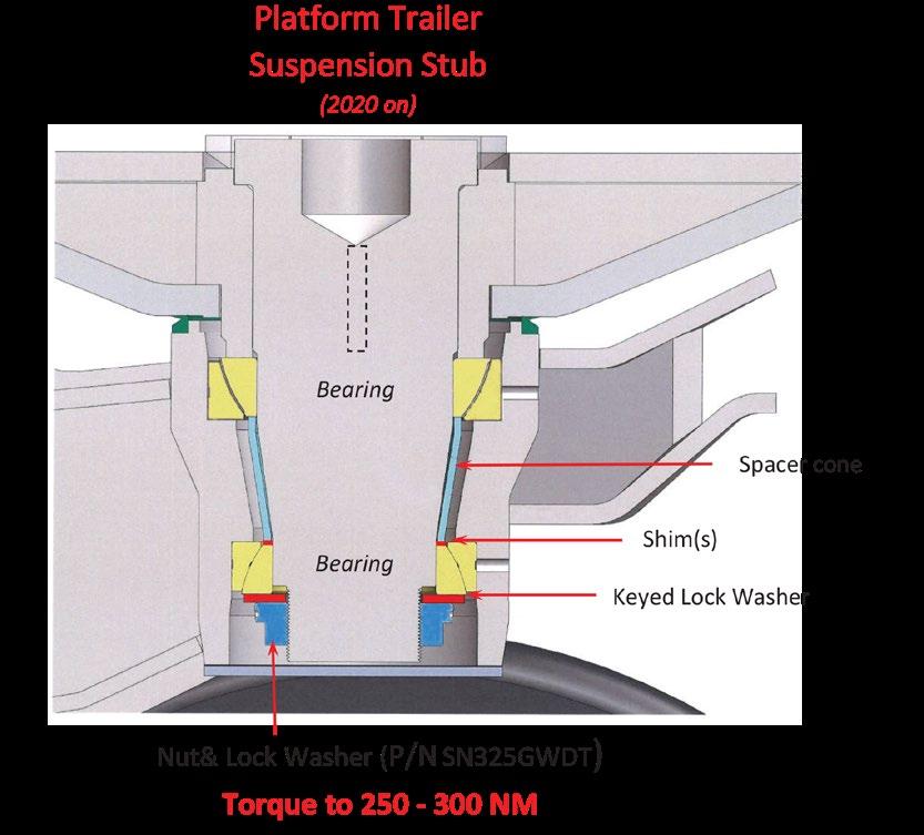
Platform trailer steering stub
Twelve Monthly
As per six monthly check.
Check wheel bearings.
Check S-cams for wear and replace as necessary.
Replace wheel bearing grease.
Check trailer registration.
NOTE:
NOTE:
Check manufacturers guidelines for non TRT components such as axles, greasing systems etc.
Wheel nuts must be re-torqued after the first 100km of refitting a wheel.
8.2 Greasing
8.2.1 Steering
This trailer has been supplied with Groeneveld Auto Greasing system. Please see the Groeneveld greasing appendix at the rear of this manual for commonly required parts and settings. The grease pump is located under the front of the Left side pontoon.
This manifold greases all the steering points (except the main ‘kingpin’ that the leg pivots on when steering).
Grease Manifolds - Gooseneck
The larger manifold greases the slew ring. The smaller manifold greases the compensator and ram.
8.2.2 Suspension Leg
This manifold greases all the points on the suspension leg (except the main ‘kingpin’ that the leg pivots on when steering).
8.2.3 Suspension Leg King Pin
The main suspension king-pin requires CASTROL SBX2 GREASE
CASTROL SBX2 is a low-friction grease specifically used in this application. Failure to use this grease, or mixing in a different grease, will significantly increase the resistance in the steering system.
(The axle being greased must have its wheels elevated slightly to allow grease into the bearings).
Failure to use this grease, or mixing in a different grease, will significantly increase the resistance in the steering system.
Do not use Castrol SBX2 grease in other areas of the trailer. The graphite grease will lock up the distributor manifolds.
CASTROL SBX2
Automatic Greasing Systems
Elbow Swivels
Reducing Adapters
Stud elbow adapters 90°
Straight adapters
8.3 Accumulators
The Accumulator Emergency Steer (AES) system and the Compensating Gooseneck, both use accumulators as stored energy. These accumulators are designed to operate at a calculated precharge pressure. See section ‘7.1 Accumulator Pre-charging’ for Accumulator precharge checking and adjusting procedure information.
Don’t wind valve actuator handle in too hard or it will damage the valve core.
NOTE:
NOTE:
If oil is present at the “gas end” of the accumulator it is unserviceable. Wind in the valve actuator until the gauge shows pressure (or the actuator bottoms out). Gauge now shows pre-charge pressure.
8.4 Electrical enclosures
Main enclosure.
External
Ignition switch.
Emergency shut down switch.
Remote control receiver.
Internal
Relays.
Fuses.
Controllers.
8.5 Welding
Please read and understand the following cautions.
Major components of this trailer are made from high tensile steel, PREHEATING BEFORE WELDING is essential to avoid post weld cracking.
Please contact TRT for welding procedures and consumable specifications before welding.
Failure to contact TRT to gain the proper weld procedure could cause additional failures and may result in the warranty being voided.
The batteries MUST be disconnected on both the trailer and the tractor unit. The Isolator on the electrical enclosure must be turned OFF before welding.
Failure to disconnect the batteries and Isolate electronics could cause electronic component failure and / or software corruption.
8.6 Water Blasting
Do not power wash any delicate areas that could be damaged. These could be electrical enclosures, connections and brake valves. Do not have the water blaster nozzle closer than 1 meter from any electrical connection.
When pressure washing avoid all delicate areas especially:
Electrical Enclosures and plug connections.
Hydraulic Valves - located centrally (in between decks) down length of trailer configuration.
8.7 Platform Trailer Leg Transfer Options
1. Ensure truck is connected to trailer and truck brakes are on. Raise Trailer to safe working height, lock all legs, do not engage brakes on trailer wheels.
2. Install blocks or dunnage around wheels being worked on and under main chassis web. Blocking wheels is essential to prevent them rolling away/kinking over as bearings/shims are inspected.
3. Remove dust cover under leg.
4. Remove locking grub screws and inspect condition of flange nut. If nut loose, remove to inspect condition of locking gear and washer, check against photos at end of document. Replace if necessary. ENSURE trailer leg is extended, keeping it pressed into stub before removal of flange nut.
5. Tighten flange nut to 500 Nm, check end float and record data. If end float is less than. 1.0 mm, proceed to step 22. If out of tolerancemore than 1.0 mm, move to step 6.
6. Loosen flange nut, undo until it meets the end of the threads (Do not completely undo the nut initially).
7. Ensure everyone is clear from under trailer, including people working on legs before proceeding to next step.
and dangerous. Remove shim by feeding it down through the leg.
11. Raise leg until upper bearing is seated, lock off leg. People may return to working on other legs/under the trailer.
12. Inspect lower bearing cup (outer shell) for any wear (Galling, scratching, deformation) and record observations.
8. Unlock leg being worked on and use leg ram suspension ram to lower it until lower bearing cone has dropped onto the now loose flange nut. KEEP CLEAR OF LEG WHILE LOWERING/RAISING AT ALL TIMES. NOTE: If bearing cone has been secured using Loctite 680 previously, heating to 150 °C will melt the retaining compound,-,and the cone will drop out.
9. Raise leg, remove flange nut and check if shim has dropped with bearing. If it has, continue to step 11. If shim is still stuck to spacer cone, continue to next step (10).
10. Carefully lower leg until shim can be dislodged from spacer cone from above. WARNING: Do not drop leg so that it clears the stub, this will result in leg rolling over and off completely, making refitment very difficult
13. Inspect shim for any wear, and record observations. Check thickness is within tolerance (+/- 0.1 mm).
14. Remove/Replace shim, following directions of table below.
15. Inspect locking washer & Locking gear. If the locking tang on either is badly damaged, they will need to be rebuilt via welding, then grinding/filing back into shape. See picture at end of instructions for examples of how they should look ex-factory.
16. Assemble the lower bearing cone, locking washer, locking gear, and flange nut onto the stub. Grease the threads of the stub and the flange of the nut as they are done up.
Platform Trailer Leg Transfer Options Cont...
17. Torque the nut to 400 Nm and take an end float reading. Check it is close to what is expected in the table below.
18. Disassemble the lower bearing cone, locking washer, locking gear, and flange nut, and clean the lower bearing cone mounting stub area using brake clean and clean rags. Apply Loctite Surface Primer SF7471, following the directions listed on the product.
19. Apply Loctite 680 retaining compound to the lower bearing cone and install it on the stub. Assembly the locking washer, locking gear, and flange nut.
20. Torque flange nut to 500 Nm.
21. Re-check end float and record.
22. If the grub screws no longer line up between teeth, torque the nut further, up to 800 Nm. If it continues to not line up, removal of the flange nut and flipping the toothed washer will move it by half a tooth.
23. Clean any grease from the threads before installing the lock nut. Excessive brake-clean and rags will be required.
24. Install lock nut, using Loctite. use Loctite high strength thread locker, 277.
25. Torque lock nuts to 800 Nm.
8.8 Brake Adjustment
8.8.1 Symptom of out of adjustment brakes
Actions:
Inspection
• Observe the ‘Brake actuation bar’ for every axle set on the trailer
• The bar should be at 90° to the brake chamber rod
• If it is not the brakes need to be adjusted
• Manuall pull the bar towards the front of the trailer (the direction of Brake Application) If it moves more than 20mm the brakes need adjusting.
Adjustment:
• Raise the trailer to a comfortable working height and lock off all axles except the one required for adjustment
• Raise the axle slightly off the ground
• Adjust BOTH slack adjusters anticlockwise until the brakes bind and the wheels cannot be rotated by hand
• Observe the brake bar. If it is not at 90° to the brake chamber rod, Un-adjust the slack adjuster that has tipped the bar rearwards.
8.8.2
Replacing the brake Chamber
In the event that the Brake chamber develops an internal or external leak, OR the output bush shows signs of damage, the brake chamber will need to be changed.
NOTE:
NOTE: The service brake diaphragm can be changed but the emergency brake diaphragm is retained by a VERY powerful spring.
DO NOT ATTEMPT TO OPEN THE EMERGENCY BRAKE END OF THE CHAMBER
• Park the trailer brakes and fit the threaded key into the back of the brake chamber. Wind the nut up to take and hold the force of the spring
• Remove the brake chamber and measure the length of the brake rod from the chamber face to the end of the rod.
• Fully compress the spring in the new chamber by applying air to the spring-brake port, or by applying the key and winding the spring back into its compressed state.
• Cut the rod on the new chamber to the same length as the old chamber and set the chamber angles up as described above.
For further information or questions regarding this service bulletin please contact: oemwarranty@tiddrosstodd.com
8.8.4
8.9
Brake-Camber Preparation
The brake chambers on Platform Trailers need to be orientated correctly and the actuator shaft cut to the correct length before fitting to the trailer.
HANDLE WITH CARE!
Do NOT tamper with the springbrake portion of a brake chamber. It contains a very powerful spring that is under compression
• The spring retention bolt locks the spring brake spring from moving.
• Apply air to the spring brake port to compress the spring.
• Remove the dust-cap from the rear of the brake chamber and insert the retention bolt. You will have to locate the tangs of the bolt into the slots inside the spring brake end then turn it CLOCKWISE a little, to key it in place. (When it is keyed in place it will not pull out).
• Slide the washer onto the bolt and wind the
NOTE:
If you do not have air available to force the spring closed it can be wound closed using the retention bolt. The spring must be FULLY compressed BEFORE releasing the bolts on the clamp.
nut down until it is tight.
• When the clamp bolts are released the front cover will come away from the diaphragm. Reposition the front cover so that the mount bold and ports are in line (Ensure the Diaphragm is positioned correctly) then refit the clamps.
• Rotate the clamps to approx. 2 and 10 o’clock looking at the rear of the brake chamber and using the ports as 12-O’clock, to ensure clearance on the tyres.
• Tighten the clamps to 30-35lbs/ft. (41 -47Nm).
• Cut the actuator rod @ 55mm with the rod retracted (Air applied to the spring brake
Spring Brake End
Spring Retention Bolt
Service Brake End
Service Brake Clamp
Diaphram
8.10 Accumulator Pre-Charging
Check the accumulator pre-charge pressure every 3 months or sooner when in doubt regarding its operation.
Read instructions through completely before you start to familiarise yourself with the procedure. Set-up
1. Lock the suspension valves.
2. Ensure the powerpack is turned off.
3. Move the suspension levers up and down a few times to release any residual pressure.
4. Close the accumulator isolation valves on the side of the trailer being worked on.
5. Loosen suspension hose from one accumulator until it is loose, do not remove.
6. SLOWLY open the accumulator isolation valve (be prepared to contain any spillagesection 2).
7. When the isolation valve is fully open remove the hose completely from the fitting.
NOTE:
If the trailer is fitted with counterbalance valves in the suspension lines there will be residual pressure in the suspension circuit. Proceed carefully realising that each accumulator may contain oil.
8. Set up the test kit as per drawing below:
9. The accumulator isolation valve must be OPEN.
10. Assemble the charging unit as per the drawing shown.
Accumulator Pre-charge
20ltr (G/N ram) 730 psi.
35ltr (ESS Emergency supply) 1200psi.
(Accumulator manufacturer: STAUFF, most hydraulic service agents should have a universal charging kit).
8.11 Suspension Lock Valve
Servicing
Over the course of time the Lock Valve mechanism can fail due to wear in the drive ‘biscuit’ or a valve seizing.
Valve function check if failure is suspected
1. Make the trailer safe by lowering onto dunnage.
2. Turn the powerpack off (section 5).
3. Drain the AES to remove pressure (section 5).
4. Ensure all other lock valves are in the lock position to reduce residual pressure escape.
5. Disconnect lines, be cautious as there will be some residual pressure.
6. Remove the hoses from one end of the lock valve and, with the valve in the open position attempt to pass a (clean) rod through the valve. (It should pass through both sides of the valve.)
7. Repeat the above test with the valve in the closed position.
8. If failure is proven - remove and strip the valve for repair or replacement.
Reassembly notes
1. Check that BOTH valves open and close and are not in any way seized or binding.
2. Start assembly with both valves in the open position.
3. Carefully position the limit plates to allow the valve to operate through its required motion.
4. Inspect the drive biscuit for wear in the square and the handle thread, replace as required.
5. Reassemble and check operation before fitting to trailer.
6. Check that the valve operates correct to the instruction decals.
LIMIT PLATE AND LIMIT PIN
DRIVE BISCUIT AND HANDLE
8.12 Changing a Wheel
To remove wheels from an axle:
1. Ensure the trailer is on flat, level, stable ground.
2. Set the trailer at ride height.
3. Lock the suspension valves on all other axles.
4. Lift wheel set enough to remove wheels.
By following this procedure the trailer can not move, minimising risk of harm to personnel changing the wheel.
8.9.1 Wheel Nut Torque
Check wheel nuts for firm seating.
After the first run under load conditions and likewise after each wheel change:
Tighten wheel nuts crosswise using a torque wrench to the tightening torque given in the table.
In the case of Trilex wheels, tighten the nuts consecutively several times around.
Wheel nuts must be torqued after the first 100km. Australian trailers must have the wheel nuts torqued before leaving the port. NOTE:
Tightening torques for wheel nuts.
Wheel Stud Alignment
mounting
8.13 Alignment
9. Groeneveld Grease System
Zero System Basic Diagnostic tests
Zero System Basic Diagnostic tests
To test system
Locate timer unit normally under dash in relatively easy to access location such as behind fuse panel, radio binnacle or glove box .
Make sure vehicle air pressure is up, turn on ignition depress red button on timer for a second and release, a pumping phase of 3 minutes will begin, a small click inside timer would be heard / felt to signify this notes:
a. The timer may automatically start a cycle once the ignition is turned on either because
1. It was at the time point one was required or
2. A cycle was in progress when the ignition was switched off so an automatic restart was activated In either of these cases leave ignition on for at least 3 mins prior to testing
b. once a pump phase has started depressing the test button will do nothing until a full 3 minutes has elapsed
Once the test has commenced power is supplied to the air solenoid on the base of pump, allowing air pressure to enter pump piston chamber this pressure is applied to the grease master cylinder, which in turn forces grease down main line and holds the pressure for the entire pump phase. The timer will check that the pressure switch has been activated 2 minutes into the pump phase, if no pressure switch signal is received an internal alarm buzzer will sound for the remaining one minute, until the air pressure is released signifying the end of the pump phase.
The most common problem encountered is air locks in the mainline which occur if the system is allowed to run low or empty. The system requires bleeding to rectify this.
To bleed, trace end/s of mainline which will be at a block of metering units where the mainline enters but the exit port is blanked off, remove blank plug activate system approx 15 – 20 times to each mainline end port in turn to save time system activation is best done by applyi ng battery power & earth direct to the solenoid terminals 10sec onds on 10 seconds off to purge the grease through
Re test system on completion of bleed
Checking Electrics
1. Ensure good clean power and earth to Timer “if in doubt locate new sources and rea ttach”
2. Turn on ignition
3. Depress test button and release timer should be felt to click
4. W ith multi meter check for power at pin 4 “Red wire” if no power remove main timer plug and inspect terminals for poor connection then re test if still no power replace timer.
5. With Multimeter check for power at solenoid plug use both solenoid wires for power and earth of multi meter
6. if power cant be achieved at solenoid plug check for continuity to earth with Multimeter the red wire should have no continuity the Brown wire should have full continuity with no discernable resistance
7. IF there is any signs of incorrect resistance at this point recheck at 3 pin plug just before timer problem if this resolves problem replace pump harness
8. Problem still evident continue to check timer harness replace timer harness
Timer Wiring
Red/yellow trace= Ignition Power pins 1 & 12 on timer, Brown = Earth “common to all” Pins 3 &/or 9 “connected internally in timer” , Red = Solenoid Power pin 4 yellow = Pressure switch
Pump wiring
3 core Red = solenoid + , yellow = Pressure switch +, Brown = Earth “ common to both PS & Solenoid”
Automatic Greasing System SingleLine
Preface
This general manual gives a description of the SingleLine Automatic Greasing System. It aims at giving insight in the system’s operation and possibilities. Furthermore, in this manual you will find the technical data on several components of the automatic greasing system. In this manual the following icons are used to inform or warn the user:
ATTENTION
Draws the user's attention to important information meant to avoid problems.
WARNING
Warns the user for physical injuries or serious damage to the equipment caused by improper actions.
Use of symbols
Automatic Greasing System SingleLine
1.General information
1.1Introduction
With an automatic greasing system of Groeneveld all grease points of a vehicle or machine are greased automatically at the correct moment and with the correct amount of grease. Because greasing takes places while the vehicle or machine is in operation, the applied grease is spread optimally over the whole surface to be greased. The greasing system requires no user intervention to operate, apart from periodically replacing the grease in its reservoir.
Groeneveld’s automatic greasing systems are designed with the utmost care and tested rigorously. This guarantees an extended operational life and error-free operation, even under the most extreme operating conditions.
Proper installation, using the correct type of grease, and periodic checks are prerequisites for the continual hassle-free operation of the system. The periodic checks, which take little time and effort, can be performed during the normal maintenance of the vehicle or machine (during oilreplacement, for instance). Careful selection of construction materials, makes the greasing system itself nearly maintenance-free.
ATTENTION
The automatic greasing system reduces the time and effort spent on manual greasing significantly. However, do not forget that there may be grease points that are not served by the greasing system and must still be greased by hand.
1.2The SingleLine automatic greasing system
Each system consists of a pump with an integral reservoir, a timer (SLT), a primary line, one or more distribution blocks, metering units, secondary lines and connectors. Grease is transferred from the reservoir by the pump, via the primary line, to the distribution blocks.
Each metering unit is connected by a secondary line to a grease point. An SLT or a pneumatically operated impulse counter, depending on whether there is a continuous electrical supply available, is used to determine when greasing occurs.
Generally only trailers and semi-trailers are equipped with a pneumatic (brake) impulse counter since they usually do not have a continuous electrical supply.
There are two main types of pump:
•electrically operated pumps (with SLT)
•pneumatically operated pumps (with SLT or pneumatic impulse counter).
The electrically operated pump is used mainly for installations or vehicles without a compressed air supply. The electrically operated pump is also used for installations where a large grease delivery is required. The delivery is larger as the pump operates for longer periods.
2.4System with electric axial plunger pump
1.Pump
2.SLT
3.Ignition switch
4.Battery
Figure 2.5System with electric axial plunger pump
5.Primary line
6.Secundary line
7.Metering unit
8.Distribution block
The SLT starts the plunjer pump. The grease in the reservoir is pumped through the primary line, to the distribution blocks.
Simultaneously the metering units press a certain amount of grease (the dosage) through the secondary lines to the grease points. The amount of grease that goes to each of the grease points depends on the type of metering unit installed.
A pressure control valve - built into the pump unit - maintains a constant pressure of 100 bar in the system during the greasing cycle. If the grease pressure exceeds 100 bar this valve will redirect the grease back toward the reservoir.
During the greasing cycle, the integrated pressure switch must report to the SLT that the minimum required pressure (70 bar) has been attained. If the SLT does not receive this signal it will generate an alarm signal.
The greasing cycle ends when the SLT stops the pump. The pressure in the primary line then slowly drops to zero via an electrically controlled relief valve. The metering units then automatically refill themselves after which they are ready (after 2 minutes) for the next greasing cycle.
Automatic Greasing System SingleLine
3.3The electric axial plunger pump
3.3.1Pump unit
1.follower plate
2.reservoir
3.guide rod of follower plate
4.low level switch
5.plunger pump
6.coupling for primary grease line
7.electric connector
figure 12.1The electric axial plunger pump
8.pressure switch
9.electric motor
10.return valve
11.filler port
12.overflow port
13.filter
14.pressure control valve
3.3.2Principle
of operation
The plunger pump (5) consists of six fixed plungers amid a ring duct. The six plungers are driven by the electric motor (9) through a mechanical transmission.
In the channel between the ring duct and the outlet (6) of the pump unit, a pressure control valve (14) and an electrically operated return valve (10) have been built-in. The pressure control valve is used to maintain a constant grease pressure during the pump cycle. The return valve allows the grease pressure in the primary line to fade after the pump cycle has ended.
The plunger pump is fitted with a pressure switch (8), which is used to check that the required grease pressure is attained during a pump cycle.
An low level switch (4) in the reservoir will cause the SLT to generate an alarm signal when the level of the grease becomes too low.
The pump is electrically connected with the SLT through the connector (7).
The reservoir (2) is mounted on top of the pump unit. The reservoir is filled via the filler port (11).
A filter (13) prevents contamination of the grease in the reservoir.
When filling the reservoir with grease the air above the follower plate (1) escapes. This air flows downward through an opening in the guide rod (3) and leaves the pump via the overflow port (12).
The escape of a small quantity of grease via this connector during venting is quite normal.
3.3.3Technical
data
Plunger pump:
electrical connection: pin 1: plus pin 2: minus pin 3: pressure switch pin 4: low level switch
1.The output of the pump is specified in cubic centimetres (cc) per minute. If the greasing system is to operate properly however, the pump should have supplied the total quantity of grease required by the system before 95% of the greasing cycle has elapsed. The length of the cycle must be set accordingly. This will guarantee that the grease pressure reaches a minimum value of 80 bar and that the pressure switch in the pump will report this fact to the SLT. If the SLT does not receive this signal, it will generate an alarm signal.
2.Operating temperatures below -15°C
Oil pumps:
at extreme circumstances please consult your local Groeneveld-organization
4.SingleLine Timer
The SingleLine Timer (SLT) is a multifunctional Groeneveld product and is composed with highgrade components to guarantee the control of the Groeneveld SingleLine greasing system.
1.Pump cycle rotary switch
2.Connection for diagnosis
3.Grease interval rotary switch
4.Test button
5.Connector
Figure 4.1SingleLine Timer (SLT)
The SLT contains a grease interval rotary switch (3) with pre-defined time intervals in order to grease a connected greasing system with the correct time interval.
If greasing interval times are not applicable the SLT can be switched to a pulse counter mode with the pump cycle rotary switch (1).
The SLT controls the connected greasing system to a number of received pulses for example from brake lights or pulse switch.
Apart from greasing intervals controlled by time or pulses it is possible to set the pump time to its applicable type of pump, length of the primary line, size/number of metering units and temperature. Essentially, a correct setting is required.
A red test button (4) is situated at the SLT, which can be used for testing and adjusting the greasing system.
The alarms for possible system errors are indicated by an internal alarm buzzer and/or an alarm signal lamp to have optimal control of the Groeneveld SingleLine greasing system.
The SLT contains a memory bank for storing data and malfunctions, which can be diagnosed by its applicable SingleLine PC-GINA program, through the available diagnostic connection (2).
Groeneveld advises to carefully read the PC-GINA user’s instruction prior to connecting the PC-GINA software to the SLT.
The following paragraphs explain how to set SLT for your Groeneveld automatic greasing system.
4.1Adjusting the greasing interval time
The greasing interval time can be adjusted with the grease interval rotary switch (Figure 4.1/3) at the SLT. Rotate the switch by using a suitable screwdriver, to the desirable position. As a confirmation, a short audible beep sounds when rotating the switch in each position. A greasing cycle starts automatically after every completed greasing cycle and set greasing interval time.
Ensure the pump-time-rotary switch, can vary between 1 and 9 minutes, is set correctly. Please refer to paragraph 4.3 Determining and adjusting the pump time. 1 3 4 5 2
4.2Adjusting the greasing interval pulses
The greasing interval pulses can be adjusted with the rotary switch (Figure 4.1/3) at the SLT. Rotate the switch by using a suitable screwdriver to the desirable position. As a confirmation, a short audible beep sounds when rotating the switch in each position. A greasing cycle starts automatically after every completed greasing cycle and the set number of pulses.
Ensure the pump-time-rotary switch is set to 0 in order to operate the SLT as a pulse counter, along with a fixed 3-minute pumping time. Please refer to paragraph 4.3 Determining and adjusting the pump time.
4.3Determining and adjusting the pump time
After venting the greasing system and a proper installation the pumping time has to be determined and pre-set.
Please follow the next steps in order to determine the pumping time.
1.Remove the rubber plug at the site of the SLT.
Adjustment possibilities of the pump cycle rotary switch (Figure 4.1/1)
•Position 0 = Activated as pulse timer with a pump time of 3 minutes.
•Position 1 = 1 minute pump time
•Position 2 = 2 minutes pump time
•Position 3 = 3 minutes pump time
•Position 4 = 4 minutes pump time
•Position 5 = 5 minutes pump time
•Position 6 = 6 minutes pump time
•Position 7 = 7 minutes pump time
•Position 8 = 8 minutes pump time
•Position 9 = 9 minutes pump time
WARNING
At position 0 the SLT will act as pulse timer. Therefore pin 8 of the SLT connector (Figure 4.1/5) requires to be connected to the brake lights or pulse switch for example. Hereby the pumping time is locked into a fixed value of 3 minutes and not changeable.
2.Turn rotary switch (Figure 4.1/1) to position 9.
If ignition is on when turning this rotary switch a short audible beep will sound in each position.
3.Switch ignition on.
ATTENTION
Ensure, prior to proceed with step 4, that the greasing system functions properly, is filled up with grease, vented and pressureless
4.Manually operate one greasing cycle, by pushing the red test button (Figure 4.1/4) until a short audible beep will sound, hence release the test button and a greasing cycle starts momentarily.
Record the time between the manually started greasing cycle and the on-pressure signal. The on-pressure signal can be identified when the internal alarm buzzer sounds an 3-second audible-pulsing signal.
The recorded time between the manually started cycle and the on-pressure signal depends on type of pump, length of the primary line, size/number of metering units and temperature. Therefore it is important to set this correctly.
5.Turn the rotary switch of the pump time (Figure 4.1/1) to the correct position after determining the pumping time between the manually started greasing cycle and the onpressure signal. The correct position: round the determined pumping time to the next full minute and add one minute (see example).
6.Close the sealing plug.
Example:
•Pump starts and the SLT receives an on-pressure signal after 38 seconds for example.
•Add 1 minute.
•The total time becomes 1:38.
•Rotate the pump cycle switch to position 2.
•Close the sealing plug.
4.4Test button functions
4.4.1Manually start one greasing cycle with a on-pressure buzzer signal
Push the red test button (Figure 4.1/4). After 1 seco nd a short audible beep will sound. Release the test button and a greasing cycle starts momentarily.
During the greasing cycle, if greasing system functions properly, a 3-second pulsing on-pressure signal will sound. This confirms the SLT received an on-pressure signal.
Possible malfunctions are represented by the alarm buzzer and/or signal lamp.
After switching ignition off or when a current cycle test finished the SLT will revert to an automatic mode.
4.4.2Manually start 10 greasing cycles
Push the red test button (Figure 4.1/4) for 6 seconds. After the short audible beep sounds a pulsing audible beep follows. Accordingly release the te st button and a 10-greasing-cycle program starts momentarily. Only in this mode the interval times between the greasing cycles are equal to pumping time pre-set by the rotary switch.
Possible malfunctions are represented by alarm buzzer and/or signal lamp.
ATTENTION
During the 10-greasing-cycle program no on-pressure signals will sound.
After switching ignition off or when this 10-greasing-cycle program is finished the SLT reverts to the automatic mode.
4.4.3Switch the alarm buzzer off/on
The SLT is provided with an alarm buzzer and an alarm signal lamp output to warn the operator in case of malfunctioning of the greasing system and a low grease level (if a low level switch is provided in the reservoir).
Both the alarm buzzer and alarm signal lamp are enabled as default setting, the operator can define whether to be warned by the alarm buzzer and/or alarm signal lamp. If the alarm buzzer is not desirable it can be disabled. Although, it would then be required to install the alarm signal lamp in a visionable area of the operator, to enable the control of the greasing system.
Disabling the buzzer
ATTENTION
In this case installing a alarm signal lamp is necessary!
1.Ensure that the SLT is not powered.
2.Push the red test button.
3.Switch ignition/power on.
4.Release the red test button.
5.A short pulsing audible beep indicates the buzzer is disabled.
Enabling the buzzer
1.Ensure that the SLT is not powered.
2.Push the red test button.
3.Switch ignition/power on.
4.Release the red test button.
5.A short audible beep indicates the buzzer is enabled.
4.5Alarm signals
The alarm signals are shown during or after the greasing cycle by the alarm buzzer and/or the alarm signal lamp.
Repetitive malfunctions will be represented in succession after detecting the error, by the buzzer and/or the alarm signal lamp.
When parameter of the alarm signal lamp is selected to light continuously by the SingleLine PCGINA program, the alarm signal lamp will light continuously after detecting an error. If not disabled, the alarm buzzer continues to act with audible beep-function.
4.5.1Alarm signal lamp
When a alarm signal lamp is installed, dedicated signals are shown during or after the greasing cycle, and will be reset automatically at factory defaults after finishing the greasing cycle. If malfunctions are present on the next greasing cycle they will be represented again to warn the operator for possible malfunctioning.
Optional: It is possible to select the alarm signal lamp to always-on after an alarm signal by the SingleLine PC-GINA program.
This is an option that can be applicable for stationary machines to where the standard lamp function is insufficiënt or poorly visible.
If this option is selected and alarm signal is continuously shown it can be reset after resolving the malfunction with the red test button as follows:
1.Switch ignition on.
2.Push the red test button (Figure 4.1/4) for 0.5 seconds.
3.Alarm signal lamp will go off.
4.Alarm signal lamp lights up at the next greasing cycle when malfunction has not been resolved.
5.If malfunction has been resolved the alarm lamp remains off.
4.6Technical data
F125639
Supply voltage 12...24Vdc
Pump output Yes
Maximum current pump output 15 A
Alarm lamp output Yes
Maximum current alarm lamp output 1 A
Impulse lamp output Yes
Maximum current impulse lamp output 1 A
Pressure switch input Yes
Low level switch input
Test
Built-in alarm beeper Yes
Greasing intervals adjustable 10, 15, 20, 30, 45, 60, 90, 120, 150, 180, 240 and 300 minutes or pulses
Pump cycle time adjustable 1,2,...9 minutes
Protection class IP54
Diagnosis connector Yes
4.7Wiring diagram
Figure 4.2Wiring diagram of SLT
Needed fuse depends on the type of pump and thickness/ length of the wiring to be connected.
Fuse at power wire to pin 12
or 2,5
Wiring on pin 3, 4, 9 and 12 Pin 12 connected to: Ignition power (+15) When switching off the ignition power (p in 1 and 12) during a greasing cycle the SLT stops the started greasing cycle The unfinished greasing cycle sta rts again after switching on the ignition power on pin 1 and 12. Battery power (+30) It is very useful to connect pin 12 to battery power when th e operator runs his vehicle or machine for very short periods. When switching off the ignition power (pin 1) during a greasing cycle the SLT will finish the started greasing cycle even without the ignition power. The next greasing cycle starts after switch ing on the ignition power (pin 1) a nd the remaining cycl e time or pulses.
Connect pin 8 for example to the brake lights or pulse switch. This connection is only needed when the SL T is set to pulses. See also paragraph 4. 2 on page21 and paragraph 4.3 on page21.
5.Impulse counter
As a rule trailers and semi-trailers do not have a continuous electrical supply. For this reason an SLT cannot be used. In its place a brake impulse counter will be used. This may be electrically or pneumatically operated.
5.1Electric brake impluse counter
1solenoid valve
2screw for manual operation (test)
Pcompressed air connection
Apump connection
Rventing outlet
Figure 5.1Electric brake impulse counter
5.2Pneumatic brake impulse counter
1signal air
2screw for manual operation (test)
Pcompressed air connection
Apump connection
Rventing outlet
Figure 5.2Pneumatic brake impulse counter
The pneumatic impulse counter starts the greasing cycle after a set number of pulses. The electrically operated counter (Figure 5.1) is activated by an electric signal. If the brakes of the vehicle are applied the solenoid valve of the pneumatic impulse counter is energized, causing the operating cam to be rotated. With a pneumatically operated impulse counter (Figure 5.2)
Impulse counter
activation is through pulses from the pneumatic system before the relay valve (or trailer reaction valve). The compressed air operates a piston, which in turn rotates the operating cam.
After the preset number of pulses the operating cam opens the air valve through which compressed air passes to the pump. The greasing cycle then begins. After a further number of pulses, depending on the setting of the counter, the pump is vented through the venting outlet R.
5.3Setting
the number of brake applications
Figure 5.3Setting the brake impulse
The number of pulses required for the counter to activate the pump, is set as follows:
1.Remove the transparent cover.
2.Set the distance (Figure 5.3/L) between the left-hand side of the striker (1) and the head of the adjusting bolt (2). The distances equivalent to a specific number of pulses are shown on the transparent cover. A feeler-gauge (3) is fixed to the inside of the cover and can be used to set this distance. The tool is marked with the number of pulses related to each thickness.
3.Tighten the lock nut (4) of the adjustment bolt.
4.Replace and secure the cover.
REMARK
Setting the pneumatic impulse counter is easier when the pneumatic line is under pressure. This moves the cam striker to the right so that the distance between the striker and the adjustment bolt can be measured.
5.4Technical data
6.Metering units
Figure 6.1Distribution block with metering units
There are 11 metering unit types (1) available for the SingleLine system, each with a differing metered grease quantity. By careful selection of the type of metering unit each grease point can be provided with the right quantity of grease.
The metering units are fitted in groups on a distribution block (2); this is a cast brass distribution block to which the primary line (3) is connected. The blocks are available with several ports or outlets to which metering units can be connected. The unused outlets should be blanked-off.
The metering units are also made of brass and are, because of their enclosed design, exceptionally suitable for use in dirty and dusty conditions. It is not advisable to open the metering units as this allows the entry of dirt, and thus is a potential cause of faults.
6.1Types of metering units
The delivery (per greasing cycle) of a metering unit is determined by the number and thickness of the spacers mounted between the head and the housing of the metering unit (Figuur 6.2).
The following metering units are available:
Figuur 6.2Types of metering units
6.2Operating principle
6.2.1Point of departure
Figure 6.3Metering unit in initial position
Figure 6.3 illustrates a new metering unit. One that has not yet been filled with grease. Item (1) is the spacer, which determines the delivery of the metering unit (see paragraph 6.1).
The metering units that are used in your greasing system may differ externally, or even internally, from the one illustrated here. However, the operating principle is always the same.
6.2.2Phase A
Figure 6.4Metering unit in phase A
The grease is pumped via the primary line and the distribution block into the channel (1) of the metering unit. The grease pressure pushes plunger (4) past channel (2). The grease now fills chamber (3) and pushes plunger (5) to the right. The stroke length of plunger (5) determines the amount of grease that will be pressed through the secondary line to the grease point. This stroke length, hence the capacity of chamber (3), is determined by the number and thickness of the spacers (Figure 6.3/1).
6.2.3Phase B
Figure 6.5Metering unit in phase B
When the pump stops and as the grease pressure in the primary line drops, spring (7) will push plunger (4) back to the left, closing off channel (1). O-ring (9) prevents grease from being sucked back from chamber (6). Plunger (5) is pushed back by spring (10) and presses the grease in chamber (3), via channel (2), to chamber (8).
6.2.4Phase C
Figure 6.6Metering unit in phase C
During the next greasing cycle the same happens as in phase A. Chamber (8), however, is now filled with grease. As plunger (4) moves to the right by the grease pressure, the grease in chamber (8) is pressed via chamber (6) and the secondary line to the grease point.
During all this, O-ring (9) is pressed outward to allow the grease to leave chamber (8).
7.Other components
7.1Solenoid valve
Figure 7.1Solenoid valve
The solenoid valve (Figure 7.1) between the air tank and the pneumatic pump (usually fitted to the pump) is a normally closed, free venting type. The valve is connected electrically by an M24 screw connector.
7.1.1Technical data part number
type
operating pressure
power requirement
screw thread
normally-closed with open venting
maximum 10 bar
maximum 8 W
M24
normally-closed with open venting
maximum 10 bar
maximum 8 W
M24
F102816 (12 V)
F102815 (24 V)
7.2Pressure switch
Figure 7.2Pressure switch
A pressure switch is included in the greasing system (in the primary line) to provide an alarm for too low a pressure in the system during the greasing cycle.
This switch closes at a pressure of 40 bar, making a connection to earth. If this does not happen during the greasing cycle, because insufficient or no grease pressure is generated, an alarm will be given. During the remaining cycle time there will be an intermittent alarm signal. This alarm will be repeated after a preset time if the problem is not corrected.
An M24 screw connector connects the pressure switch electrically.
For a system with a pneumatic pump the pressure switch is fitted to a distribution block. The electrically operated pump is provided with a built-in pressure switch.
7.2.1Technical data
7.3Reservoir
Figure 7.3Pneumatic pump
The reservoir (2) is made from impact-resistant plastic that can withstand the influences of fluctuating temperatures. The reservoir can hold a quantity of grease that in most cases is sufficient for about 4 months, depending on the number of grease points.
The minimum level (5 cm) is marked by a label (3) on the reservoir.
7.4Follower plate
In the standard reservoir a follower plate is placed above the level of the grease (Figure 7.3/1). This plate follows the level of the grease; as the level falls the follower plate falls with it under the action of a tension spring. The follower plate prevents the increase of air into the grease and any consequent soaping of the grease. Funneling of grease as the level falls is also prevented. The follower plate also wipes the reservoir wall clean. This allows the level of the grease to be checked easily at a glance.
8.Refilling the reservoir
8.1Grease recommendations
The use of the correct grease in the Groeneveld Automatic Greasing System is important. The grease to be used must be an NLGI 0-grease of EP quality and moreover must not contain graphite. Groeneveld has developed an EP grease in the NLGI class 0 especially for use in automatic greasing systems. This grease - Greenlube EP-0 - combines the best qualities of various types of greases. The use of Greenlube grease is recommended for the greasing system. If you use another type of grease or are not sure about the use of your own grease, please consult eiher the lubricant supplier of Groeneveld.
8.2Filling the reservoir
Figure 8.1Filling the reservoir
When the grease in the reservoir has fallen to the minimum level it must be refilled. Generally a filler pump is used for this purpose (see Figure 8.1). The procedure is as follows:
•With a new filler pump (or filling hose) the hose should first be primed with grease. This avoids the pumping of air into the reservoir. For this the ball (1) in the snap-on connector on the filler hose should be depressed while pumping grease through the hose until it is filled with the grease.
•Remove the dust cap from the filler connector.
•Carefully clean the filler connector and the connector on the filler hose.
•Secure the filler hose to the filler connector.
•Fill the reservoir to not more than the maximum level (2 cm below the top of the reservoir) or until the follower plate meets its stop.
•Remove the filler hose.
•Replace the dust cap on the filler connector.
•There is a filter within the filler connector in the reservoir. If pumping is very difficult the filter could be blocked. In this case, dismantle and clean the filter.
9.Maintenance
9.1General
The maintenance of Groeneveld’s SingleLine greasing systems can be combined with the normal maintenance of the vehicle or machine.
WARNING
When cleaning the vehicle or machine with a high-pressure water/steam jet cleaner, the pump of the greasing system should not be directly exposed to the jet. This to prevent water from entering the pump through its venting opening. During normal operation, however, water will never be able to enter the pump.
ATTENTION
The automatic greasing system reduces the time and effort spent on manual greasing significantly. However, do not forget that there may be grease points that are not served by the greasing system and must still be greased by hand (for example the universal joints of the propeller shaft).
9.2Periodic checks
1.Check the pump, paying particular attention to the level of the grease (top up in time) and external damage.
2.Check the SLT with particular reference to the correct operation of the various functions. For this an accelerated test should be carried out. See chapter 4.
3.Check the brake impulse counter and pay attention to the manometer on the pump. Operate the brake impulse counter manually by means of the screw.
4.Check the entire system and in particular for damage of lines and operation of the metering units.
10.Fault diagnosis
10.1General malfunction reports
Fault
1. All points to be greased are dry.
a. Pump reservoir is empty. a. Fill the reservoir. See chapter 8.
b. Reservoir filled with grease that is too thick and unsuitable for the system.
c. Primary line leaking.
d. SLT or pneumatic impulse counter not set correctly.
If there is another cause, please consult your dealer.
b. Remove and clean the reservoir. Refit and fill the reservoir with the correct grease. Remove the end plugs from the distribution blocks and pump the old grease out of the system.
c. Repair the line and bleed the system if a new piece of line has been fitted.
d. Reset the SLT or brake impulse counter.
2. Pump does not work or does not reach working pressure.
a. Pneumatically operated pump: No or too-low air pressure.
b. Piston does not rise.
If there is another cause, please consult your dealer.
3. One or more grease points are dry while the others receive sufficient grease.
4. A grease point receives too much grease.
5. Pneumatically operated pump: Solenoid valve fails to operate or does not operate correctly.
a. Break in the secondary line.
b. Inoperative metering unit.
a. Internal leak in the metering unit.
a. Bad or open electrical connections.
6. SLT does not operate.
7. Too much grease at all grease points.
b. Solenoid valve internally fouled with water and/or rust from the vehicle air system.
a. Fuse blown.
a. System greasing frequency does not correspond with vehicle operating conditions.
a. Ensure there is an air pressure of 6 to 8 bar.
b. Dismantle the cover of the pump casing and clean the piston.
a. Repair or replace the line.
b. Remove the metering unit and fit a new unit.
a. Remove and clean the metering unit or fit a new unit.
a. Check the electrical circuit and connections to the solenoid valve. Check the valve with direct current bypassing the SLT. Watch out for short-circuits!
b. Dismantle, clean and refit the valve or fit a new valve. Clean the vehicle air system.
a. Fit new fuse.
b. Reduce the greasing frequency. Do not be too sparing, it is better to grease too much than too little.
10.2Malfunction report of the SLT
Malfunction
Low level measured in reservoir.
ATTENTION!
Only applicable if a low level switch has been installed in the reservoir.
Pump aborted an greasing automatically.
Reservoir (almost) empty and the SLT reads no pressure signal anymore during a greasing cycle.
ATTENTION!
Only applicable if a low level switch has been installed in the reservoir.
Non or insufficient measured grease pressure during a greasing cycle.
Grease pressure measured before cycle.
Alarm buzzer / alarm signal lamp
1 short audible beep and/or alarm lamp signal 30 seconds pulsing.
Fill the reservoir as soon as possible. After filling the reservoir the message resets automatically.