PROFI LINE PRODUCTS

PRO
Scan this code to watch TESY corporate video
ABOUT TESY
TESY is one of the leading European producers of electric storage water heaters, indirectly heated water tanks, electric heating appliances and heat pump water waters.
In the last decade TESY showed a rapid development and introduced to the world a wide range of cutting-edge products and patented solutions that meet the current requirements for energy efficiency and environmental protection.
The company continues its development by investing in the latest technologies, its production capacity expansion and launching new product offerings..
Since October 2017, TESY has been an official member of the EHPA (European Heat Pump Association), which aims to provide technical support and financial support to European, national and local authorities on legislative, regulatory and energy efficiency matters.
TESY is also member of the European Technical Commission that works directly on the development of European regulations regarding energy efficiency, for which we carry out laboratory tests and analyses of electric water heaters in order to verify and validate the methodology described in the European regulations.
We set our hearts and minds on bringing warmth into your life.


MISSION VISION
Raising the bar in our industry, to be globally recognised as a leader of innovation and design in hot water and heating sоlutions. More comfort with a single touch.
VALUES
PASSION
We are a passionate team of enthusiastic professionals with ambitious goals. Leading by example, we create a culture that inspires people to go the extra mile. We put our hearts and minds in everything we do to embrace dynamic change.
INNOVATION
TESY people are open-minded, eager to learn and inspired to create.
Challenging the status quo, we employ the latest technologies in supreme functionality and impressive design.
TRUST
The shared vision for openness and integrity is the core virtue of TESY’s long-term partnerships.
Supportive, loyal and trustful, we offer reliable products and service quality with respect for the individual.

Page 2 Page 3 TESY in numbers
4 FACTORIES MORE THAN 55 COUNTRIES MORE THAN 840 EMPLOYЕES 4 CONTINENTS
TESY Mission, Vision, Values
committed to
Cоrporate Sоcial Respоnsibility
all business
and practices
thus minimise the environmental impact

production.
strive to constantly improve established processes and we
strictly following
regulations for
protection.
our focus is on efficiency, our appliances
use alternative
Page 4 Page 5 Corporate Social Responsibility TESY is
integrate
into
policies
and
during
We
are
all
environmental
As
can also
sources of energy. Corporate Social Responsibility plastics/year steel/year 94 % 445 m3 26 000 m3 105.3 MW/h 70.8 kW/h 104 t 66 t 3 000 t 130 t paper/year wood cellulose electricity electricity CO2 emissions iron ore electricity crude oil water water 35 t 2 000 t 85 % 75 % 40 % 92% of TESY's waste is handed over for recycling and / or recovery. of the packages of the supplied chemical substances and solvents used in production are reusable packs. TESY produces appliances that can be connected to alternative sources of energy. By handing over paper for recycling TESY annually saves: By handing over steel for recycling TESY annually saves: By handing over plastics for recycling TESY annually saves:
MAIN ADVANTAGES:
Highly-efficient
very low
certain ranges of products. The


jacket
its shape and ensures good aesthetics throughout the product life.


Page 6 Page 7 in
PS
preserves
Uniform distribution High density No thermal bridge Innovations
insulation ensuring
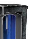
standing losses. Environmentally friendly materials (100% recyclable, made with 70% recycled materials). Precise alignment of the water tank and the external jacket for achieving an even thickness of the insulation covering the tanks vertical walls, without a chimney effect. Thermal insulation fleece with improved performance compliant with the European energy efficiency standards. Closure system by zipper that enables the insulation to be easily dismantled. INSU PRO is a new specially developed technology for highly-efficient insulation in PROFI products of large capacity 750 L - 2000 L. NEW INSULATION TECHNOLOGY
INDEX
About
Mission, Vision,
step motor
Heat Pump Water Heaters
Heat Pump water heaters AquaThermica
Domestic Hot Water Indirectly Heated Water Tanks
Domestic hot water tanks with high output heat exchangers
Domestic hot water tanks with two, one and without heat exchangers
Domestic hot water tanks with two inlets and two outlets
Domestic hot water tanks with innovative elliptic heat exchangers
Domestic hot water tanks with two parallel heat exchangers
Domestic hot water tanks for installation under wall-hung gas boiler
Enameled buffer tanks for Heat Pump Systems
Combined Indirectly Heated Water Tanks
Combined Buffer Tanks with corrugated stainless steel hygienic heat exchanger
Combined Buffer Tanks with integrated enameled tank (tank-in-tank)
Buffer tanks
Buffer Tanks with two, one and without heat exchangers
Buffer tanks for Heat Pump systems
Non-enameled buffer tanks for Heat Pump Systems
Solar energy systems
Solar energy systems Accessories
Indirectly Heated Water Tanks Heating elements and Accessories
elements and accessories
Page 8 Page 9 Content
TESY
Values Corporate Social Responsibility Innovations Content
Heating
TESY uses different pictograms for highlighting the main benefits TESY symbols Energy efficency class A+A+ ErP Up to 75% reduced electricity consumption Up to savings 75% 65ºC DHW with the heat pump only 65˚C DHWLow CO₂ emissions CO2 Electronic
for precisely balanced refrigerant cycle ERV modulation Operational temperature range -10 to +43ºC -10˚C + 43˚C Connectivity to Solar and PV panels 3 Bar Rated pressure 8 Bar Rated pressure 6 Bar Rated pressure 10 Bar Rated pressure Renewable Energy User-friendly LCD Display LCD New Insulation Technology INSU PRO 3 Bar 8 Bar 6 Bar 10 Bar Page 2 Page 3 Page 4 Page 6 Page 8 Page 10 Page 12 Page 16 Page 18 Page 28 Page 46 Page 56 Page 62 Page 66 Page 70 Page 74 Page 76 Page 84 Page 90 Page 92 Page 104 Page 110 Page 114 Page 116 Page 118 Page 121 Page 122
HEAT PUMP WATER HEATERS AQUATHERMICA
ADVANTAGES
HEAT PUMP WATER HEATERS -

AquaThermica is the TESY family of heat pump water heaters for domestic hot water production.
This family includes models of 200 L and 260 L, with or without a heat exchanger.
Advantages:
It is an environmentally friendly product, operating with renewable energy sources resulting in lower CO2 emissions1
The highest energy efficiency class A+ in its category, according to ErP regulations.
Progammable with a user-friendly control panel.
Operates within a wide temperature range of the incoming air from -10°С to +43°С.
Heats the water up to 65°C with the heat pump only.
Electric heating element for faster heating up and reaching of higher temperature of 75°С.
Highly efficient 2 with a precisely balanced refrigerant cycle due to an electronically commutated motor and an electronic expansion valve.
Up to 75% lower electricity consumption3
It can be connected to other energy sources like PV and solar systems or boilers.
Automatic anti-legionella cycle. Self-diagnostic system.
1 - According to the European Market and Statistical Report on the European Heat Pump Association 2018.
2 - AquaThermica is in energy efficiency class A+.
3 - Compared to a TESY product of the MaxEau family GCV 200 56 20 D06 SRC in energy class C.
Page 10 Page 11
Scan this code to watch TESY product video: A+ ErP Up to savings 75% CO2 -10˚C + 43˚C 65˚C DHW ERV modulation LCD 8 Bar
Fan
Operating conditions
Working temperature
Page 12 Page 13 Heat Pump Water Heaters | AquaThermica | 200 L and 260 L Model AquaThermica 200 + heat exchanger HPWH 2.1 200 U 02 S AquaThermica 200 HPWH 2.1 200 U 02 AquaThermica 260 + heat exchanger HPWH 2.1 260 U 02 S AquaThermica 260 HPWH 2.1 260 U 02 Art. Number № 305061 305005 305062 305004 Performance Declared load profile L L XL XL Heat pump thermal power yield; prated Condition EN16147:2017 A7/W55 kW 1.1 1.1 1.2 1.2 Heating time ; Condition EN16147:2017 A7/W55 h:m 08:59 08:59 10:15 10:15 COP DHW Condition EN16147:2017 A7/W55 2.8 2.8 3.0 3.0 COP DHW Condition EN16147:2017 A14/W55 3.1 3.1 3.4 3.4 Energy efficiency class Climate condition EN16147:2017 average A+ A+ A+ A+ Annual electricity consumption Climate condition EN16147:2017 average kWh 867 867 1355 1355 Sound power Lw(A) EN12102-2:2019 dB(A) 53 53 53 53 Electrical data Power supply (Frequency) V (Hz) 1 / N 230 (50) Degree of protection IPX4 HP maximum absorption kW 0.663 + 1.5 (e-heater) = 2.163 Average heat pump consumption Condition EN16147:2017 A7/W55 kW 0.43 0.43 0.466 0.466 Electric heating element power kW 1.5 Maximum current in HP A 3.1 + 6.5 (e-heater) = 9.6 Required overload protections A 16A T fuse/ 16A automatic switch, characteristic C (to be expected when connected to a power supply system) Internal protection Safety thermostat with a manual reset on a resistive element
Min. ÷ max temperature heat pump air intake (90% R.H.) ℃ -10 ÷ 43 Min. ÷ max temperature installation site ℃ 4 ÷ 43
HP Maximum settable temperature ℃ 75 Design characteristic Compressor / compressore protection Rotary / thermal circuit breaker with an automatic reset Thermodynamic circuit protection type Safety pressure switches with an automatic reset; [high/low pressure 2.5/0.1 Mpa]
Centrifugal Nominal air capacity m³/h 314 Max. pressure head available Pa 98 Motor protection Internal thermal circuit breaker with an automatic reset Condenser Wound externally, not in contact with the water Automatic anti-Legionnella cycle Yes Defrosting 4-way valve Refrigerant R134a Refrigerant charge g 880 Global warming potential 1430 CO2 equivalent t 1287 Water storage tank Water storage tank capacity L 194 202 251 260 V40* EN16147:2017 L 262 272 339 351 Internal heat exchanger for auxiliary source m² 1.0 N/A 1.2 N/A Cathodic protection Mg anode Ø32x400 mm Insulation - ridig PU mm 50 Transport weight kg 112 96 128 110 Maximum working pressure bar 8 All models can be ordered in a box. *Max. quantity of hot water at 40 C. Heat Pump Water Heaters | AquaThermica | 200 L and 260 L Thread designations according to EN ISO 228-1! MODEL HPWH 2.1 200 U 02 S HPWH 2.1 260 U 02 S HPWH 2.1 200 U 02 HPWH 2.1 260 U 02 CW cold water inlet G 1" G 1" HW hot water outlet G 1" G 1" IS heat exchanger inlet G 1" OS heat exchanger outlet G 1" TS thermo pocket G ½" R recirculation G ¾" G ¾" EE opening for electric element G 1½" G 1½" D condensate drainage G ¾" G ¾" MA Magnesium anode G 1¼” G 1¼” ThS Safety thermostat G 1” G 1” Ø D 0 k j n f d u h CW IS TS OS R HW D R a b 0 EE MAThS M Ø DF w Air Inlet Air Outlet Dimensions ±5 mm HPWH 2.1 200 U 02 S HPWH 2.1 200 U 02 HPWH 2.1 260 U 02 S HPWH 2.1 260 U 02 h mm 1720 1720 2010 2010 a mm 994 994 1285 1285 b mm 724 724 834 834 d mm 995 995 1285 1285 f mm 803 803 1064 1064 mm 681 781 k mm 60 60 60 60 n mm 681 681 766 766 u mm 1153 1153 1440 1440 w mm 58 58 58 58 M mm 260 260 260 260 Ø DF mm 160 160 160 160 R mm 1785 1785 2055 2055 Ø D mm 630 630 630 630
AIR-DUCT SYSTEM INSTALLATION


AIR OUTLET DUCT ONLY DUAL DUCT CONNECTION FOR DRYING PREMISES


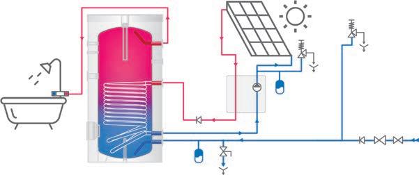
Page 14 Page 15 Heat Pump Water Heaters | AquaThermica | Connection schemes CONNECTION TO PV PANEL CONNECTION TO PV PANEL AND TO A SOLAR COLLECTOR CONNECTION TO A PV PANEL AND A BOILER Heat Pump Water Heaters | AquaThermica | Operating principle and Installation Outside air in Evaporator Compressor Condenser Storage tank Cold air out Warm gas Warm liquid Cold liquid Expansion valve Hot gas Hot water outlet Cold water inlet Air outlet duct only Dual duct connectionAir outlet duct only Dual duct connection For drying premises
Applications for cooling/ drying premises
INSTALLATION
IN WINTER
INSTALLATION
IN SUMMER
DOMESTIC HOT WATER TANKS WITH HIGH OUTPUT HEAT EXCHANGERS


ADVANTAGES
8 Bar
DOMESTIC HOT WATER TANKS FOR HEAT PUMP SYSTEMS


Floor-standing indirectly heated water tanks for domestic hot water production, with double heat exchangers with an internal collector and large surface, suitable for use with low-temperature heat carriers. This product family is specially designed for heat pump systems.
The range includes models:
from 200 L to 1000 L with two double high output heat exchangers (lower solar heat exchanger) from 160 L to 1000 L with a double high output heat exchanger from 300 L to 500 L with high output heat exchangers
Advantages:

Heat exchangers with large surfaces for connection to heat pump or condensing gas boiler systems. Suitable to operation with low temperature heat carriers. Decreased hydraulic resistance (pressure drop) of the heat exchanger with a larger diameter of the inlet and outlet on 1.1/2”. High quality enamel coating CrystalTech PRO and two magnesium anodes, which protect whole inner surface of the tank for a longer product life.

The models up to 500 L are insulated with a high efficiency PU insulation (models in energy class C and B) and have a service opening for easy maintenance.
Highly-efficient INSU PRO insulation upon request for the models 800 L and 1000 L.


Page 16 Page 17
Domestic
Heat
V40 - hot
Reheat time
flow rate
primary side (S1) Coil 80⁰ min/(l/min) 35.71/(41.7) 35.2/(50) 41.5/(58.3)

Heat exchanger reheat performance P at flow rate of primary side (S2)Coil 80⁰ kW/(l/min) 38.1/(41.7) 53.8/(50) 74.6/(58.3)
V40 -hot water delivered with a temperature of at least 40 °C (S2)Coil 80⁰ L 203 292.1 450.3
Reheat time 10-60°C flow rate at primary side (S2)Coil 80⁰ min/(l/min) 10.35/(41.7) 5.7/(50) 12.7/(58.3)
Heat exchanger reheat performance P at flow rate of primary side (S1) Coil 55⁰ kW/(l/min) 6.6/(50) 7.8/(50) 11.8/(50)
V40 - hot water delivered with a temperature of at least 40 °C (S1) Coil 55⁰ L 253 375 601

Reheat time 10-50°C flow rate at primary side (S1) Coil 55⁰ min/(l/min) 73.58/(50) 89.31/(50) 98.56/(50)
Heat exchanger reheat performance P at flow rate of primary side (S2) Coil 55⁰ kW/(l/min) 14.6/(50) 18.9/(50) 26.1/(50)
V40 - hot water delivered with a temperature of at least 40 °C (S2) Coil 55⁰ L 158 237 395
Reheat time 10-50°C flow rate at primary side (S2) Coil 55⁰ min/(l/min) 20.18/(50) 24.03/(50) 28.98/(50)
Coil pressure drop at flow rate m3/h (S1) mBar/(l/min) 27.7/(41.7) 30.7/(50) 71.4/(58.3)
Coil pressure drop at flow rate m3/h (S2) mBar/(l/min) 42.1/(41.7) 62.8/(50) 105.2/(58.3)
** 10℃ - cold water temperature, 60℃ - hot water temperature (domestic water)

Page 18 Page 19 Domestic hot water tanks for heat pump systems | with two double high output heat exchangers | 200 L to 500 L MODELS EV 2x4 2x9 S2 200 60 HP EV 2x5 2x12 S2 300 65 HP EV 2x6 2x13 S2 500 75 HP Art.number № 305254 305255 305249 Capacity L 185 269 459 Net weight kg 90 122 183 Insulation (PU) mm 50(rigid) 50(rigid) 50(rigid) Heat exchanger surface S1 m2 0.65 1 1.55 Heat exchanger capacity S1 L 4 6 9.3 Heat exchanger surface S2 m2 1.6 2.45 3.45 Heat exchanger capacity S2 L 9.5 14.7 21 Heat losses ∆T45K W 1.4 1.6 2.3 Energy efficiency class B B C Maximum operational temperature °C 95 95 95 Maximum operational temperature of heat exchanger °C 110 110 110 Rated pressure bar 8 8 8 Rated pressure of the heat exchanger bar 6 6 6
exchanger reheat performance P at flow rate of primary side (S1) Coil 80⁰ kW/(l/min) 17.9/(41.7) 24.6/(50) 36.5/(58.3)
water delivered with a temperature of at least 40 °C (S1) Coil 80⁰ L 326 459 729.4
10-60°C
at
INSTALLATION AND CONNECTION SCHEME E E Ø C Ø D TR IS 2 R OS 2 OS 1 CW TS 1 TS 2 TS 3 IS 1 T HW d 0 k n g m e l f 0 c a h AA s e ec c t t i i o o n n A A AA MA2 MA1
hot water tanks for heat pump systems | with two double high output heat exchangers | 200 L to 500 L TS3 is not available in 200 L model Thread designations according to EN ISO 228-1! for ALL MODELS CW cold water inlet G 1" HW hot water outlet G 1" IS1 heat exchanger inlet G 1 ½" IS2 heat exchanger inlet G 1 ½" OS1 heat exchanger outlet G 1 ½" OS2 heat exchanger outlet G 1 ½" R recirculation G ¾" T thermometer Ø14x1.5 TR opening for thermoregulator G ½" TS1 thermo sensor pocket level 1 G ½" TS2 thermo sensor pocket level 2 G ½" TS3 thermo sensor pocket level 3 G ½" EE opening for electric element G 1½" MA magnesium anode G ¾” MA2 magnesium anode 2 G 1½” Dimensions ±5mm EV 2x4 2x9 S2 200 60 HP EV 2x5 2x12 S2 300 65 HP EV 2x6 2x13 S2 500 75 HP h mm 1197 1420 1677 a mm 996 1184 1447 c mm 483 533 642 d mm 996 1184 1447 e mm 966 1150 1325 f mm 817 1055 1162 g mm 519 574 706 mm 434 485 572 mm 202 205 225 k mm 202 205 225 l mm 817 1055 1262 m mm 726 864 n mm 360 398 467 R mm 1345 1560 1823 ØC mm 600 650 750 ØD mm 500 550 650
Heat exchanger reheat performance
V40 -hot water delivered with a temperature
least
1330.7 1354.7
Reheat time 10-60°C flow rate at primary side (S1) Coil 80⁰ min/(l/min) 51.05/(100) 49.81/(100)
Heat exchanger reheat performance P at flow rate of primary side (S2) Coil 80⁰ kW/(l/min) 75.6/(100) 104/(100)
V40 -hot water delivered with a temperature of at least 40 °C (S2) Coil 80⁰ L 703.6 784.6
Reheat time 10-60°C flow rate at primary side (S2) Coil 80⁰ min/(l/min) 17.98/(100) 17.7/(100)
Heat exchanger reheat performance P at flow rate of primary side (S1) Coil55⁰ kW/(l/min) 16.2/(50) 17.0/(50)
V40 -hot water delivered with a temperature of at least 40 °C (S1) Coil55⁰ L 1043.5 1078
Reheat time 10-50°C flow rate at primary side (S1) Coil 55⁰ min/(l/min) 122.93/(50) 140.86/(50)
Heat exchanger reheat performance P at flow rate of primary side (S2) Coil 55⁰ kW/(l/min) 25.1/(50) 28.0/(50)
V40 -hot water delivered with a temperature of at least 40 °C (S2) Coil 55⁰ L 526.4 670
Reheat time 10-50°C flow rate at primary side (S2) Coil 55⁰ min/(l/min) 43.51/(50) 53.26/(50)
Coil Pressure drop at flow rate m3/h (S1) mBar/(l/min) 638.5/(100) 349.4/(100)
Coil Pressure drop at flow rate m3/h (S2) mBar/(l/min) 660/(100) 440.9/(100)
** 10℃ - cold water temperature, 60℃ - hot water temperature (domestic water) Highly-efficient INSU PRO insulation upon request for the models 800 L and 1000 L.
Page 20 Page 21 Domestic hot water tanks for heat pump systems | with two double high output heat exchangers | 800 L to 1000 L MODELS EV 2x9 2x14 S2 800 95 HP DN18 EV 2x9 2x17 S2 1000 101 HP DN18 Art.number № 305391 305392 Capacity L 741 921 Net weight kg 307 324 Insulation mm 100(soft) 100(soft) Heat exchanger surface S1 m2 2.5 2.5 Heat exchanger capacity S1 L 14.3 14.4 Heat exchanger surface S2 m2 3.8 4.6 Heat exchanger capacity S2 L 14.9 27.5 Heat losses ∆T45K W 3.1 3.4 Energy efficiency class C C Maximum operational temperature °C 95 95 Maximum operational temperature of heat exchanger °C 110 110 Rated pressure bar 8 8 Rated pressure of the heat exchanger bar 6 6
P at flow rate of primary side (S1) Coil 80⁰ kW/(l/min) 49.4/(100) 63.2/(100)
of at
40 °C (S1) Coil 80⁰ L
INSTALLATION AND CONNECTION SCHEME Domestic hot water tanks for heat pump systems | with two double high output heat exchangers | 800 L to 1000 L Thread designations according to EN ISO 228-1! for ALL MODELS CW cold water inlet G 1½" HW hot water outlet G 1½" IS1 heat exchanger inlet G 1 ½" IS2 heat exchanger inlet G 1 ½" OS1 heat exchanger outlet G 1 ½" OS2 heat exchanger outlet G 1 ½" R recirculation G ¾" T thermometer Ø14x1.5 TR opening for thermoregulator G ½" TS1 thermo sensor pocket level 1 G ½" TS2 thermo sensor pocket level 2 G ½" TS3 thermo sensor pocket level 3 G ½" AV air ventilation G ¾” EE opening for electric element G 1½" MA1 magnesium anode 1 G1¼” MA2 magnesium anode 2 G 1¼” Dimensions ±5mm EV 2x9 2x14 S2 800 95 HP DN18 EV 2x9 2x17 S2 1000 101 HP DN18 h mm 1974 2012 a mm 1591 1625 c mm 810 734 d mm 1779 1846 e mm 1572 1625 mm 1272 1374 g mm 910 834 mm 710 637 mm 410 337 k mm 82 81 mm 1435 1374 m mm 1005 919 n mm 575 470 R mm 2124 2270 ØC mm 990 1050 ØD mm 790 850 ЕЕ AV MA1 MA2 section A-A
V40 -hot water delivered with a temperature of at least 40
(S1)
Reheat time 10-60°C flow rate at primary side (S1)

min/(l/ min) 12.5/(33.3) 13.5/(41.7) 10.7/(41.7) 13.2/(50) 10.88/(50) 10.8/(58.3) 11.7/(58.3)
Heat exchanger reheat performance P at flow rate of primary side (S1) Coil 55⁰ kW/(l/ min) 14.9/(50.0) 18.8/(50.0) 23.0/(50.0) 25.2/(50.0) 27.0/(50.0) 37.1/(50.0) 35.7/(50.0)
V40 -hot water delivered with a temperature of at least 40 °C (S1) Coil 55⁰ L 165 262 240 383 340 468 500


Reheat time 10-50°C flow rate at primary side (S1) Coil 55⁰ min/(l/ min) 24.45/(50) 25.81/(50) 20.25/(50) 27.68/(50) 23.73/(50) 23.18/(50) 30.0/(50)


Coil Pressure drop at flow rate m3/h


Page 22 Page 23 Domestic hot water tanks for heat pump systems | with one double high output heat exchanger | 160 L to 500 L MODELS EV 2x10 S 160 60 HP EV 2x12 S 200 60 HP EV 2x15 S 200 60 HP EV 2x15 S 300 65 HP EV 2x19 S 300 65 HP EV 2x19S 400 75 HP EV 2x23 S 500 75 HP Art.number № 304703 305251 305250 305257 305256 305248 305231 Capacity L 149 186 183 271 267 369 451 Net weight kg 65 89 102 106 130 162 183 Insulation (PU) mm 50(rigid) 50(rigid) 50(rigid) 50(rigid) 50(rigid) 50(rigid) 50(rigid) Heat exchanger surface S1 m2 1.7 2.1 2.56 3 3.84 5.05 6 Heat exchanger capacity S1 L 11 12.5 15.6 18.3 23 31 33 Heat losses ∆T45K W 1.2 1.4 1.4 1.6 1.6 2.2 2.3 Energy efficiency class B B B B B C C Maximum operational temperature °C 95 95 95 95 95 95 95 Maximum operational temperature of heat exchanger °C 110 110 110 110 110 110 110 Rated pressure bar 8 8 8 8 8 8 8 Rated pressure of the heat exchanger bar 6 6 6 6 6 6 6 Heat exchanger reheat performance P at flow rate of primary side (S1) Coil 80⁰ kW/(l/ min) 36.5/(33.3) 46.3/(41.7) 55.2/(41.7) 63.8/(50.0) 73.0/(50.0) 101.7/(58.3) 117.2/(58.3)
°C
Coil 80⁰ L 205 327 299 450.5 357.4 567 662.3
Coil 80⁰
(S1) kW/(l/ min) 30/(33.3) 53.3/(41.7) 56.6/(41.7) 71.9/(41.7) 94.9/(50.0) 171.5/(58.3) 173.2/(58.3) ** 10℃ - cold water temperature, 60℃ - hot water temperature (domestic water) INSTALLATION AND CONNECTION SCHEME AA h f i 0 a c 0 Ø C Ø RD H W Td R T S 3 T S 2 m T S 1 n T S R CW k O S s e c t o on n A A E E MA1 MA2 Domestic hot water tanks for heat pump systems | with one double high output heat exchanger | 160 L to 500 L Dimensions ±5mm EV 2x10 S 160 60 HP EV 2x12 S 200 60 HP EV 2x15 S 200 60 HP EV 2x15 S 300 65 HP EV 2x19 S 300 65 HP EV 2x19 S 400 75 HP EV 2x23 S 500 75 HP h mm 1007 1202 1197 1420 1420 1400 1670 a mm 791 995 996 1184 1184 1168 1447 c mm 271 264 264 278 278 272 405 d mm 791 996 996 1184 1184 1171 1447 f mm 712 792 794 1055 953 1059 1162 i mm 602 897 919 937 1120 1118 1378 j mm 207 202 202 205 206 225 225 k mm 207 202 202 205 206 225 225 l mm 699 897 897 1055 1055 1059 1162 m mm 499 633 633 691 691 778 864 n mm 289 360 360 398 398 448 467 R mm 1169 1345 1345 1560 1560 1590 1823 ØC mm 600 600 600 650 650 750 750 ØD mm 500 500 500 550 550 650 650 Model EV 2x10 S 160 60 HP for OTHER MODELS CW cold water inlet G 1" G 1" HW hot water outlet G 1" G 1" IS1 heat exchanger inlet G 1" G 1 ½" OS1 heat exchanger outlet G 1" G 1 ½" R recirculation G ¾" G ¾" T thermometer Ø14x1.5 Ø14x1.5 TR opening for thermoregulator G ½" G ½" TS1 thermo sensor pocket level 1 G ½" G ½" TS2 thermo sensor pocket level 2 G ½" G ½" TS3 thermo sensor pocket level 3 G ½" G ½" EE opening for electric element G 1½" G 1½" MA1 magnesium anode 1 G ¾” G ¾” MA2 magnesium anode 2 G1½” G1½” TS3 is not available in 200 L model Thread designations according to EN ISO 228-1!
Heat exchanger reheat performance
V40 -hot water delivered with
flow rate
temperature
Reheat time 10-60°C flow rate at primary
at least
(S1)
(S1)Coil 80⁰ min/(l/min) 29.78/(100) 28.36/(100)
Heat exchanger reheat performance P at flow rate of primary side (S1)Coil55⁰ kW/(l/min) 26/(50) 30.3/(50)
V40 -hot water delivered with a temperature of at least 40 °C (S1)Coil55⁰ L 1033 1128
Reheat time 10-50°C flow rate at primary side (S1)Coil55⁰ min/(l/min) 78.95/(50) 74.7/(50)
Coil Pressure drop at flow rate m3/h (S1) mBar/(l/min) 666.2/(100) 675.8/(100)
V40 - hot water delivered with a temperature of at least 40℃ (S1) L 304.4 433.6
V40 - hot water delivered with a temperature of at least 40℃ (S2) L 154.3 219.4
Reheat time 10-60℃ flow rate at primary side (S1) min / (L/min) 36.5/(20.8) 35.9 /(25.0)
Reheat time 10-60℃ flow rate at primary side (S2) min / (L/min) 22.8 /(20.8) 23.85 /(25.0)
Coil Pressure drop at flow rate m /h (S1) mbar / (L/min) 21.3 /(20.8) 73.7 /(25.0)
Coil Pressure drop at flow rate m /h (S2) mbar / (L/min) 14.6 /(20.8) 54.0 /(25.0)
Page 24 Page 25 Domestic hot water tanks for heat pump systems | with one double high output heat exchanger | 800 L to 1000 L ** 10℃ - cold water temperature, 60℃ - hot water temperature (domestic water) MODEL EV 2x14 S 800 95 HP DN18 EV 2x17 S 1000 101 HP DN18 Art.number № 305407 305415 Capacity L 770 937 Net weight kg 254 297 Insulation mm 100(soft) 100(soft) Heat exchanger surface S1 m2 3.8 4.5 Heat exchanger capacity S1 L 17.2 27.1 Heat losses ∆T45K W 3.1 3.4 Energy efficiency class C C Maximum operational temperature °C 95 95 Maximum operational temperature of heat exchanger °C 110 110 Rated pressure bar 8 8 Rated pressure of the heat exchanger bar 6 6
P at
of primary side (S1) Coil 80⁰ kW/(l/min) 85.4/(100) 104/(100)
a
of
40 °C
Coil 80⁰ L 1283 1435
side
INSTALLATION AND CONNECTION SCHEME Domestic hot water tanks for heat pump systems | with one double high output heat exchanger | 800 L to 1000 L Dimensions ±5mm EV 2x14 S 800 95 HP DN18 EV 2x17 S 1000 101 HP DN18 h mm 1974 2012 a mm 1591 1625 c mm 360 374 d mm 1779 1845 mm 1272 1347 mm 971 1115 mm 309 324 k mm 81 81 m mm 1005 919 n mm 575 470 R mm 2124 2270 ØC mm 990 1050 ØD mm 790 850 for ALL MODELS CW cold water inlet G 1½" HW hot water outlet G 1½" IS1 heat exchanger inlet G 1 ½" OS1 heat exchanger outlet G 1 ½" R recirculation G ¾" T thermometer Ø14x1.5 TR opening for thermoregulator G ½" TS1 thermo pocket level 1 G ½" TS2 thermo pocket level 2 G ½" TS3 thermo pocket level 3 G ½" AV air ventilation G ¾” EE opening for electric element G 1½" MA1 magnesium anode 1 G 1¼” MA2 magnesium anode 2 G1¼” Thread designations according to EN ISO 228-1! section A-A Highly-efficient INSU PRO insulation upon request for the models 800 L and 1000 L.

Page 26 Page 27 Domestic hot water tanks for heat pump systems | with one high output heat exchanger | 300 L to 500 L MODEL EV 17S 300 65 EV 17S 400 75 EV 23S 500 75 Art. number № 301397 301398 301400 Capacity L 279 387 470 Net weight kg 102 128 160 Insulation (rigid PU) mm 50 50 50 Heat exchanger surface S1 m2 2.1 2.55 3.4 Heat exchanger capacity S1 L 12.6 15.5 23.2 Heat losses ∆T 45K W 68 91 95 Energy efficiency class B C C Maximum operational temperature ℃ 95 95 95 Maximum operational temperature of heat exchanger ℃ 110 110 110 Rated pressure bar 8 8 8 Rated pressure of the heat exchanger bar 6 6 6 Heat exchanger reheat performance P at flow rate of primary side (S1) kW / (L/min) 36.3 / (25.0) 48.4 (29.2) 60.6 / (29.2) V40 - hot water delivered with a temperature of at least 40℃ (S1) L 382.2 464.0 580.8 Reheat time 10-60℃ flow rate at primary side (S1) min (L/min) 25.6 / (29.2) 19.6 / (29.2) 18.8 / (29.2) Coil Pressure drop at flow rate m 3/h (S1) mbar / (L/min) 67.9 / (29.2) 44.6 /(29.2) 160 (29.2) * inlet temperature of the heat transfer fluid (S1/S2) 80º ** 10℃ - cold water temperature, 60℃ - hot water temperature (domestic water) INSTALLATION AND CONNECTION SCHEME Domestic hot water tanks for heat pump systems | with one high output heat exchanger | 300 L to 500 L Dimensions ±5 mm EV 17S 300 65 EV 17S 400 75 EV 23S 500 75 h mm 1420 1400 1670 c mm 371 411 405 d mm 1184 1168 1447 f mm 953 960 1161 mm 1101 1120 1378 k mm 206 225 225 mm 1055 1059 1161 m mm 691 778 680 n mm 398 448 467 R mm 1560 1590 1833 Ø C mm 650 750 750 Ø D mm 550 650 650 for ALL MODELS CW cold water inlet G 1" HW hot water outlet G 1" IS heat exchanger inlet G 1" OS heat exchanger outlet G 1" R recirculation G ¾" T thermometer Ø 14 x 1.5 TR opening for thermoregulator G ½" TS1-2-3 thermo pocket level 1-2-3 G ½" МА1 magnesium anode 1 G ¾” МА2 magnesium anode 2 G1½” Thread designations according to EN ISO 228-1! section A-A 45° AA h d i l f m n k 0 a c 0 Ø D Ø C R HWTR CW TS3 TS2 TS1 T IS R OS Ø120Ø174 MA1 MA2
DOMESTIC HOT WATER TANKS WITH TWO, ONE AND WITHOUT HEAT EXCHANGERS
Model with two inlets and two outlets
ADVANTAGES
8 Bar
DOMESTIC HOT WATER TANKS WITH HIGH EFFICIENCY


A wide range of floor-standing indirectly heated water tanks for domestic hot water production, suitable for installation in single and multi-family residential buildings as well as for commercial application.
The range includes models from 160 L to 2000 L in energy efficiency class A, B or C:
with two heat exchangers with one heat exchanger without heat exchanger with two inlets and two outlets
Advantages:


Durable enamel coating of the tank for long life. Highly-efficient CFC free PU foam insulation in models up to 500 L. INSU PRO insulation upon request models up to 2000 L. Two magnesium anode protectors at the upper and the lower area. Thermoindicator.


Service opening for easy inspection and maintenance. Heating element installation option. Thermoregulator installation pocket. Thermoprobe installation pocket.


Page 28 Page 29
Heat
Heat exchanger

V40 - hot water delivered with a temperature of at least 40℃ (S1)
V40 - hot water delivered with a temperature of at least 40℃ (S2)
(20.8)
304.4 433.6
154.3
Reheat time 10-60℃ flow rate at primary side (S1) min / (L/min) 36.5 / (20.8) 35.9 / (25.0)
Reheat time 10-60℃ flow rate at primary side (S2) min / (L/min) 22.8 (20.8) 23.85 (25.0)
Coil Pressure drop at flow rate m /h (S1) mbar / (L/min) 21.3 / (20.8) 73.7 / (25.0)
Coil Pressure drop at flow rate m /h (S2) mbar / (L/min) 14.6 / (20.8) 54.0 / (25.0)
Page 30 Page 31 Domestic hot water tanks class A | with two heat exchangers | 200 L and 300 L * inlet temperature of the heat transfer fluid (S1/S2) 80º ** 10℃ - cold water temperature, 60℃ - hot water temperature (domestic water) MODEL EV 7/5 S2 200 65 EV 10/7 S2 300 75 Art. number № 302653 302654 Capacity L 192 279 Net weight kg 68 95 Insulation (rigid PU) mm 75 100 Heat exchanger surface S1 m2 0.75 1.21 Heat exchanger surface S2 m2 0.54 0.85 Heat exchanger capacity S1 L 4.6 7.4 Heat exchanger capacity S2 L 3.3 5.2 Heat losses ∆T 45K W 41 46 Energy efficiency class A A Maximum operational temperature ℃ 95 95 Maximum operational temperature of heat exchanger ℃ 110 110 Rated pressure bar 8 8 Rated pressure of the heat exchanger bar 6 6
exchanger reheat performance P at flow rate of primary side (S1) kW (L/min) 16.4 / (20.8) 24.2 / (25.0)
reheat performance P at flow rate of primary side (S2) kW (L/min) 13.1 /
16.8 / (25.0)
L
L
219.4
INSTALLATION AND CONNECTION SCHEME Domestic hot water tanks class A | with two heat exchangers | 200 L and 300 L for ALL MODELS CW cold water inlet G 1" HW hot water outlet G 1" IS1 heat exchanger inlet G 1" IS2 heat exchanger inlet G 1" OS1 heat exchanger outlet G 1" OS2 heat exchanger outlet G 1" R recirculation G ¾" T thermometer Ø 14 x 1.5 TR opening for thermoregulator G ½" TS1 thermo sensor pocket level 1 G ½" TS2 thermo sensor pocket level 2 G ½" EE opening for electric element G 1½" МА1 Magnesium anode 1 G ¾” МА2 Magnesium anode 2 G1½” Thread designations according to EN ISO 228-1! TS1, TS2 25° section A-A BB V1 HW IS2 TS2 R OS2 IS1 TS1 OS1 CW EE F V2 T TR R section B-B k j n g f m e d h AA 00 c b a Ø D Ø C Ø174 Ø120 MA1 MA2 Dimensions ±5 mm EV 7/5 S2 200 65 EV 10/7 S2 300 75 h mm 1274 1495 a mm 993 1207 b mm 628 760 c mm 314 314 d mm 993 1207 e mm 886 1104 f mm 746 903 g mm 671 803 mm 585 718 mm 284 288 k mm 199 203 m mm 815 996 n mm 478 610 R mm 1345 1563 Ø C mm 650 750 Ø D mm 500 550
Page 32 Page 33 Domestic hot water tanks class A | with one heat exchanger | 200 L and 300 L * inlet temperature of the heat transfer fluid (S1/S2) 80º **10℃ - cold water temperature, 60℃ - hot water temperature (domestic water) MODEL EV 9S 200 65 EV 12S 300 75 Art. number № 302733 302731 Capacity L 195 283 Net weight kg 68 95 Insulation (rigid PU) mm 75 100 Heat exchanger surface S1 m2 0.96 1.45 Heat exchanger capacity S1 L 5.8 8.8 Heat losses ∆T 45K W 41 46 Energy efficiency class A A Maximum operational temperature ℃ 95 95 Maximum operational temperature of heat exchanger ℃ 110 110 Rated pressure bar 8 8 Rated pressure of the heat exchanger bar 6 6 Heat exchanger reheat performance P at flow rate of primary side (S1) kW / (L/min) 24.0 / (20.8) 28.9 / (25.0) V40 - hot water delivered with a temperature of at least 40℃ (S1) L 345.8 435.3 Reheat time 10-60℃ flow rate at primary side (S1) min / (L/min) 29.0 / (20.8) 30.35 (25.0) Coil Pressure drop at flow rate m 3/h (S1) mbar / (L/min) 31.0 / (20.8) 87.5 / (25.0) INSTALLATION AND CONNECTION SCHEME Domestic hot water tanks class A | with one heat exchanger | 200 L and 300 L for ALL MODELS CW cold water inlet G 1" HW hot water outlet G 1" IS1 heat exchanger inlet G 1" OS1 heat exchanger outlet G 1" R recirculation G ¾" T thermometer Ø 14 x 1.5 TR opening for thermoregulator G ½" TS thermo sensor pocket level 1 G ½" EE opening for electric element G 1½" МА1 Magnesium anode 1 G ¾” МА2 Magnesium anode 2 G1½” Thread designations according to EN ISO 228-1! TS1, TS2 25° section A-A BB V1 HW R IS TS OS CW EE F V2 T TR section B-B Ø D Ø C R k j n f d h AA 00 c b a Ø174 Ø120 MA1 MA2 Dimensions ±5 mm EV 9S 200 65 EV 12S 300 75 h mm 1274 1495 a mm 993 1207 b mm 714 846 c mm 314 314 d mm 771 1207 f mm 771 1010 mm 671 804 j mm 284 288 k mm 199 203 n mm 564 653 R mm 1345 1563 Ø C mm 650 750 Ø D mm 500 550

Page 34 Page 35 Domestic hot water tanks class A | without heat exchangers | 200 L and 300 L MODEL EV 200 65 EV 300 75 Art. number № 302732 302730 Capacity L 202 294 Net weight kg 48 69 Insulation (rigid PU) mm 75 100 Heat losses ∆T 45K W 41 46 Energy efficiency class A A Maximum operational temperature ℃ 95 95 Rated pressure bar 8 8 INSTALLATION AND CONNECTION SCHEME Domestic hot water tanks class A | without heat exchangers | 200 L and 300 L Dimensions ±5 mm EV 200 65 EV 300 75 h mm 1247 1495 a mm 993 1207 b mm 714 846 c mm 314 314 d mm 993 1207 mm 771 1010 k mm 199 203 R mm 1345 1563 Ø C mm 650 750 Ø D mm 500 550 TS1, TS2, TS3 25° section A-A BB Ø D V1 Ø C HW R TS2 TS1 TS3 CW EE F V2 Ø174 Ø120 T TR R k f d h AA 00 c b a section B-B MA1 MA2 Thread designations according to EN ISO 228-1! for ALL MODELS CW cold water inlet G 1" HW hot water outlet G 1" R recirculation G ¾" T thermometer Ø 14 x 1.5 TR opening for thermoregulator G ½" TS1 thermo sensor pocket level 1 G ½" TS2 thermo sensor pocket level 2 G ½" TS3 thermo sensor pocket level 3 G ½" EE opening for electric element G 1½" МА1 Magnesium anode 1 G ¾” МА2 Magnesium anode 2 G1½”
Heat
V40 - hot water delivered with a temperature of at least 40℃ (S1) L 243.2 304.4 433.6 583.3 677.6
V40 - hot water delivered with a temperature of at least 40℃ (S2) L 112.5 154.3 219.4 258.2 294.3
Reheat time 10-60℃ rate at primary side (S1) min (L/min) 37.0 / (16.6) 36.5 / (20.8) 35.9 / (25.0) 34.6 / (29.2) 33.2 / (29.2)
Reheat time 10-60℃ rate at primary side (S2) min (L/min) 23.3 / (16.6) 22.8 / (20.8) 23.9 / (25.0) 39.3 / (29.2) 25.3 / (29.2)
Coil Pressure drop at flow rate m /h (S1) mbar (L/min) 12.0 / (16.6) 21.3 (20.8) 73.7 / (25.0) 105.7 / (29.2) 109.4 / (29.2)
Coil Pressure drop at flow rate m 3/h (S2) mbar (L/min) 7.9 /( 16.6) 14.6 (20.8) 54.0 / (25.0) 65.1 / (29.2) 49.8 / (29.2)
Page 36 Page 37 * inlet temperature of the heat transfer fluid (S1/S2) 80º ** 10℃ - cold water temperature, 60℃ - hot water temperature (domestic water) MODEL EV 6/4 S2 160 60 EV 7/5 S2 200 60 EV 10/7 S2 300 65 EV 11/5 S2 400 75 EV 15/7 S2 500 75 Art. number № 302165 301407 301391 301393 301396 Capacity L 154 192 279 388 472 Net weight kg 66 70 100 146 158 Insulation (rigid PU) mm 50 50 50 50 50 Heat exchanger surface S1 m 0.61 0.75 1.21 1.65 2.25 Heat exchanger surface S2 m 0.43 0.54 0.85 0.76 1.06 Heat exchanger capacity S1 L 3.6 4.6 7.4 10 13.7 Heat exchanger capacity S2 L 2.6 3.3 5.2 4.6 6.4 Heat losses ∆T 45K W 51 59 68 91 95 Energy efficiency class B B B C C Maximum operational temperature ℃ 95 95 95 95 95 Maximum operational temperature of heat exchanger ℃ 110 110 110 110 110 Rated pressure bar 8 8 8 8 8 Rated pressure of the heat exchanger bar 6 6 6 6 6
exchanger reheat performance P at flow rate of primary side (S1) kW / (L/min) 13.5 / (16.6) 16.4 (20.8) 24.2 / (25.0) 33.9 / (29.2) 43.6 / (29.2) Heat exchanger reheat performance P at flow rate of primary side (S2) kW / (L/min) 9.9 / (16.6) 13.1 / (20.8) 16.8 / (25.0) 17.7 / (29.2) 24.9 / (29.2)
Domestic hot water tanks class B and C | with two heat exchangers | 160 L to 500 L INSTALLATION AND CONNECTION SCHEME Domestic hot water tanks class B and C | with two heat exchangers | 160 L to 500 L for ALL MODELS CW cold water inlet G 1" HW hot water outlet G 1" IS1 heat exchanger inlet G 1" IS2 heat exchanger inlet G 1" OS1 heat exchanger outlet G 1" OS2 heat exchanger outlet G 1" R recirculation G ¾" T thermometer Ø 14 x 1.5 TR opening for thermoregulator G ½" TS1 thermo sensor pocket level 1 G ½" TS2 thermo sensor pocket level 2 G ½" EE opening for electric element G 1½" МА1 Magnesium anode 1 G ¾” МА2 Magnesium anode 2 G1½” Dimensions ±5 mm EV 6/4 S2 160 60 EV 7/5 S2 200 60 EV 10/7 S2 300 65 EV 11/5 S2 400 75 EV 15/7 S2500 75 h mm 1007 1200 1420 1407 1674 a mm 785 993 1207 1156 1448 b mm 519 628 760 813 986 c mm 279 314 314 331 324 d mm 788 993 12074 1156 1448 e mm 741 886 1104 1073 1330 f mm 649 746 903 943 1165 g mm 569 671 803 858 1029 mm 475 585 718 775 944 j mm 204 284 288 302 299 k mm 204 199 203 220 214 m mm 649 815 996 998 1265 n mm 349 478 610 617 1265 R mm 649 1345 1563 1596 1838 Ø C mm 600 600 650 750 750 Ø D mm 500 500 550 650 650 Thread designations according to EN ISO 228-1! n c 0 b a h k 0 i g m f e d Ø DR Ø C HW IS2 TS2 R OS2 IS1 TS1 TS1, TS2 OS1 CW EE T TR 25° AA section A-A Ø120Ø174 MA1 MA2
Heat
Heat exchanger reheat performance
at flow rate
V40 - hot water delivered with a temperature of at least 40℃ (S1)
V40 - hot water delivered with a temperature of at least 40℃ (S2)
(100)
1095.2 1403 1933.8 2785
447.1 604 714.1 940
Reheat time 10-60℃ flow rate at primary side (S1) min / (L/min) 48.9 (50.0) 50.2 / (50.0) 45.3 / (100) 57.3 (100)
Reheat time 10-60℃ flow rate at primary side (S2) min / (L/min) 31.5 / (50.0) 40.5 / (50.0) 29.7 / (100) 34.6 / (100)
Coil Pressure drop at flow rate m /h (S1) mbar (L/min) 69.0 (50.0) 82.6 / (50.0) 222.1 (100) 294.8 / (100)
Coil Pressure drop at flow rate (S2) mbar (L/min) 119.6 / (50.0) 174.3 / (50.0) 172.5 / (100) 189.5 / (100)
Page 38 Page 39 Domestic hot water tanks class B and C | with two heat exchangers | 800 L to 2000 L * inlet temperature of the heat transfer fluid (S1/S2) 80º ** 10℃ - cold water temperature, 60℃ - hot water temperature (domestic water) Highly-efficient INSU PRO insulation upon request for the models from 800 L to 2000 L. MODEL EV 12/9S2 800 95 DN18 EV 13/7 S2 1000 101 DN18 EV 12/8 S2 1500 120 DN18 EV 15/9 S2 2000 130 DN18 Art. number № 305416 305428 305417 305431 Capacity L 757 932 1414 1822 Net weight kg 252 279 408 486 Insulation mm 100 100 100 100 Heat exchanger surface S1 m2 2.89 3.45 3.3 4.5 Heat exchanger surface S2 m2 1.54 1.31 2.3 2.75 Heat exchanger capacity S1 L 26.2 31.3 30.4 41.6 Heat exchanger capacity S2 L 9.4 7.9 20.5 25.2 Heat losses ∆T 45K W 128 142 151 183 Energy efficiency class C C C C Maximum operational temperature ℃ 95 95 95 95 Maximum operational temperature of heat exchanger ℃ 110 110 110 110 Rated pressure bar 8 8 8 8 Rated pressure of the heat exchanger bar 6 6 6 6
exchanger reheat performance P at flow rate of primary side (S1) kW / (L/min) 61.2 / (100) 77.2 (100) 94.5 / (100) 113.1 (100)
P
of primary side (S2) kW / (L/min) 35.3 /
36.5 / (100) 64.8 / (100) 77.1 / (100)
L
L
INSTALLATION AND CONNECTION SCHEME Domestic hot water tanks class B and C | with two heat exchangers | 800 L to 2000 L MODEL EV 12/9S2 800 95 DN18 EV 13/7 S2 1000 101 DN18 EV 12/8 S2 1500 120 DN18 EV 15/9 S2 2000 130 DN18 CW cold water inlet G 1½"B G 2"B HW hot water outlet G 1½"B G 2"B IS1 heat exchanger inlet G 1½"B G 1½"B IS2 heat exchanger inlet G 1"B G 1½"B OS1 heat exchanger outlet G 1½"B G 1½"B OS2 heat exchanger outlet G 1"B G 1½"B R recirculation G ¾" G 1½" T thermometer Ø 14 x 1.5 Ø 14 x 1.5 TR opening for thermoregulator G ½" G ½" TS1 thermo sensor pocket level 1 G ½" G ½" TS2 thermo sensor pocket level 2 G ½" G ½" EE opening for electric element G 1½" G 1½" AV opening for air ventilation G ¾" G ¾" МА1 magnesium anode 1 G1¼” G 1¼” МА2 magnesium anode 2 G 1¼” G1¼” МА3 magnesium anode 3 G1¼” Dimensions ±5 mm EV 12/9S2 800 95 DN18 EV 13/7 S2 1000 101 DN18 EV 12/8 S2 1500 120 DN18 EV 15/9 S2 2000 130 DN18 h mm 1947 2012 2193 2399 a mm 1592 1475 1768 1927 b mm 1051 1132 1168 1287 c mm 351 354 468 497 d mm 1778 1847 2061 2263 e mm 1492 1475 1691 1875 f mm 1273 1274 1378 1560 g mm 1105 1174 1251 1380 i mm 929 987 1081 1244 j mm 269 272 421 420 k mm 82.5 81.5 90 90 m mm 1363 1374 1329 1537 n mm 756 817 579 587 R mm 2014 2100 2361 2565 Ø C mm 990 1050 1200 1300 Ø D mm 790 850 1000 1100 Thread designations according to EN ISO 228-1! TR c 0 b a h j g f m e d Ø D Ø C n m k 0 HW IS2 TS2 R OS2 IS1 TS1 OS1 CW EE T AV A A 25° TS1, TS2 section A-A Ø274 Ø176 MA1 MA2 MA3
Page 40 Page 41 Domestic hot water tanks class B and C | with one heat exchanger | 160 L to 500 L MODEL EV 9S 160 60 EV 9S 200 60 EV 12S 300 65 EV 11S 400 75 EV 15S 500 75 Art. number № 301408 301409 301394 301392 301395 Capacity L 155 195 283 394 480 Net weight kg 54 65 92 137 145 Insulation (ridig PU) mm 50 50 50 50 50 Heat exchanger surface S1 m 0.96 0.96 1.45 1.65 2.25 Heat exchanger capacity S1 L 5.8 5.8 8.8 10 13.7 Heat losses ∆T 45K W 51 52 68 91 95 Energy efficiency class B B B C C Maximum operational temperature ℃ 95 95 95 95 95 Maximum operational temperature of heat exchanger ℃ 110 110 110 110 110 Rated pressure bar 8 8 8 8 8 Rated pressure of the heat exchanger bar 6 6 6 6 6 Heat exchanger reheat performance P at flow rate of primary side (S1) kW / (L/min) 20.3 / (16.6) 24.0 (20.8) 28.9 / (25.0) 34.5 / (29.2) 44.5 / (29.2) V40 - hot water delivered with a temperature of at least 40℃ (S1) L 203 345.8 435.3 596.7 684.6 Reheat time 10-60℃ rate at primary side (S1) min (L/min) 20.8 / (16.6) 29.0 (20.8) 30.4 / (25.0) 34.6 / (29.2) 32.9 / (29.2) Coil Pressure drop at flow rate m 3/h (S1) mbar (L/min) 14.5 (16.6) 31.0 / (20.8) 87.5 (25.0) 114.4 / (29.2) 103.2 / (29.2) * inlet temperature of the heat transfer fluid (S1/S2) 80º ** 10℃ - cold water temperature, 60℃ - hot water temperature (domestic water) INSTALLATION AND CONNECTION SCHEME Domestic hot water tanks class B and C | with one heat exchanger | 160 L to 500 L for ALL MODELS CW cold water inlet G 1" HW hot water outlet G 1" IS1 heat exchanger inlet G 1" OS1 heat exchanger outlet G 1" R recirculation G ¾" T thermometer Ø 14 x 1.5 TR opening for thermoregulator G ½" TS thermo sensor pocket level 1 G ½" EE opening for electric element G 1½" МА1 Magnesium anode 1 G ¾” МА2 Magnesium anode 2 G1½” Dimensions ±5 mm EV 9S 160 60 EV 9S 200 60 EV 12S 300 65 EV 11S 400 75 EV 15S 500 75 h mm 1007 1200 1420 1407 1674 a mm 785 993 1207 1156 1448 b mm 714 846 813 986 c mm 314 314 314 331 324 d mm 785 993 1207 1156 1448 f mm 602 771 1010 945 1199 mm 671 671 804 775 944 mm 284 284 288 302 299 k mm 200 199 203 220 214 n mm 360 564 653 617 750 R mm 1169 1345 1563 1596 1838 Ø C mm 600 600 650 750 750 Ø D mm 500 500 550 650 650 Thread designations according to EN ISO 228-1! n c b a h k 00 j f d Ø DR Ø C 25° section A-A AA TR HW R IS OS CW TS TS T EE Ø174 Ø120 MA1 MA2
Page 42 Page 43 Domestic hot water tanks class B and C | with one heat exchanger | 800 L to 2000 L MODEL EV 12 800 95 DN18 EV 13S 1000 101 DN18 EV 12S 1500 120 DN18 EV 15S 2000 130 DN18 Art. number № 305426 305429 305427 305435 Capacity L 768 932 1439 1853 Net weight kg 221 233 371 442 Insulation mm 100 100 100 100 Heat exchanger surface S1 m2 2.89 3.45 3.3 4.5 Heat exchanger capacity S1 L 26.2 31.3 30.4 41.6 Heat losses ∆T 45K W 129 142 158 183 Energy efficiency class C C C C Maximum operational temperature ℃ 95 95 95 95 Maximum operational temperature of heat exchanger ℃ 110 110 110 110 Rated pressure bar 8 8 8 8 Rated pressure of the heat exchanger bar 6 6 6 6 Heat exchanger reheat performance P at flow rate of primary side (S1) kW (L/min) 6.1 / (100) 7.2 / (100) 94.5 / (100) 113.1 / (100) V40 - hot water delivered with a temperature of at least 40℃ (S1) L 1095.2 1403 1933.8 2785 Reheat time 10-60℃ flow rate at primary side (S1) min / (L/min) 48.85 / (50) 50.15 (50) 45.3 (100) 57.26 (100) Coil Pressure drop at flow rate m 3/h (S1) mbar / (L/min) 69.0 / (50) 82.6 (50) 222.14 / (100) 294.8 / (100) * inlet temperature of the heat transfer fluid (S1/S2) 80º ** 10℃ - cold water temperature, 60℃ - hot water temperature (domestic water) Highly-efficient INSU PRO insulation upon request for the models from 800 L to 2000 L. INSTALLATION AND CONNECTION SCHEME Domestic hot water tanks class B and C | with one heat exchanger | 800 L to 2000 L MODEL EV 12S 800 95 DN18 EV 13S 1000 101 DN18 EV 12S 1500 120 DN18 EV 15S 2000 130 DN18 CW cold water inlet G 1½"B G 2"B HW hot water outlet G 1½"B G 2"B IS1 heat exchanger inlet G 1½"B G 1½"B OS1 heat exchanger outlet G 1½"B G 1½"B R recirculation G ¾" G 1½" T thermometer Ø 14 x 1.5 Ø 14 x 1.5 TR opening for thermoregulator G ½" G ½" TS thermo sensor pocket level 1 G ½" G ½" EE opening for electric element G 1½" G 1½" МА1 Magnesium anode 1 G1¼” G 1¼” МА2 Magnesium anode 2 G 1¼” G1¼” МА3 Magnesium anode 3 G1¼” Dimensions ±5 mm EV 12S 800 95 DN18 EV 13S 1000 101 DN18 EV 12S 1500 120 DN18 EV 15S 2000 130 DN18 h mm 1947 2012 2193 2399 a mm 1592 1475 1768 1927 b mm 1051 1132 1168 1298 c mm 351 354 468 497 d mm 1780 1846 2061 2246 f mm 1273 1274 1378 1551 mm 929 987 1081 1235 mm 269 272 421 411 k mm 82.5 81.5 90 90 n mm 756 830 579 578 R mm 2012 2097 2361 2592 Ø C mm 990 1050 1200 1300 Ø D mm 790 850 1000 1100 Thread designations according to EN ISO 228-1! TR c 0 b a h f d Ø D Ø C i n R k 0 HW R IS TS OS CW EE T AV A A 25° 25° TS section A-A Ø274 Ø176 MA1 MA2 MA3
Page 44 Page 45 Domestic hot water tanks class B and C | without heat exchangers | 200 L to 500 L MODEL EV 200 60 EV 300 65 EV 400 75 EV 500 75 Art. number № 301399 301402 301405 301406 Capacity L 202 294 406 497 Net weight kg 45 66 117 125 Insulation mm 50 50 50 50 Heat losses ∆T 45K W 59 68 91 95 Energy efficiency class B B C C Maximum operational temperature ℃ 95 95 95 95 Rated pressure bar 8 8 8 8 INSTALLATION AND CONNECTION SCHEME Domestic hot water tanks class B and C | without heat exchangers | 200 L to 500 L Dimensions ±5 mm EV 200 60 EV 300 65 EV 400 75 EV 500 75 h mm 1207 1427 1407 1702 a mm 993 1207 1156 1445 b mm 714 846 813 983 c mm 314 314 331 321 d mm 993 1207 1156 1445 f mm 771 1010 943 1196 k mm 199 203 220 211 R mm 1345 1563 1596 1838 Ø C mm 600 650 750 750 Ø D mm 500 550 650 650 MODEL for ALL MODELS CW cold water inlet G 1" HW hot water outlet G 1" R recirculation G ¾" T thermometer Ø 14 x 1.5 TR opening for thermoregulator G ½" TS1 thermo sensor pocket level 1 G ½" TS2 thermo sensor pocket level 2 G ½" TS3 thermo sensor pocket level 3 G ½" EE opening for electric element G 1½" МА1 Magnesium anode 1 G ¾” МА2 Magnesium anode 2 G1½” Thread designations according to EN ISO 228-1! R f c 0 b a h k 0 d Ø D AV Ø C 25° section B-B section A-A BB AA TR HW R CW TS2 TS1 TS3 TS1,2,3 T EE Ø174 Ø120 MA1 MA2

Page 46 Page 47 Domestic hot water tanks class B and C | without heat exchangers with 2 inlets and 2 outlets | 200 L to 500 L MODEL EV 200 60 B EV 300 65 B EV 500 75 B Art. number № 305599 305600 305601 Capacity L 200 300 500 Real volume L 202 294 497 Net weight kg 45 66 125 Insulation mm 50 50 50 Heat losses ∆T 45K W 59 68 95 Energy efficiency class B B C Maximum operational temperature ℃ 95 95 95 Rated pressure bar 8 8 8 INSTALLATION AND CONNECTION SCHEME Thread designations according to EN ISO 228-1! Domestic hot water tanks class B and C | without heat exchangers with 2 inlets and 2 outlets | 200 L to 500 L C 0 A A section A-A 90° T EE Dimensions ±5 mm EV 200 60 B EV 300 65 B EV 500 75 B h mm 1207 1427 1702 a mm 993 1207 1445 b mm 726 846 983 c mm 314 314 321 d mm 993 1207 1445 f mm 815 987 1215 k mm 199 203 211 l mm 993 1207 1445 m mm 734 907 1142 n mm 199 203 211 R mm 1345 1563 1838 ØC mm 600 650 750 ØD mm 500 550 650 for ALL MODELS R recirculation G ¾" T thermometer Ø14x1.5 TR opening for thermoregulator G ½" TS1 thermo sensor pocket level 1 G ½" TS2 thermo sensor pocket level 2 G ½" TS3 thermo sensor pocket level 3 G ½" EE opening for electric element G 1½" L1 Level 1 G 1" L2 Level 2 G 1" MA1 Magnesium anode 1 G ¾" MA2 Magnesium anode 2 G 1½"
Page 48 Page 49 Domestic hot water tanks class B and C | without heat exchangers | 800 L to 1000 L MODEL EV 800 95 DN18 EV 1000 101 DN18 Art. number № 305436 305221 Capacity L 796 974 Net weight kg 178 224 Insulation (rigid PU) mm 80 80 Heat losses ∆T 45K W 128 143 Energy efficiency class C C Maximum operational temperature ℃ 95 95 Rated pressure bar 8 8 Highly-efficient INSU PRO insulation upon request for the models 800 L and 1000 L. INSTALLATION AND CONNECTION SCHEME Domestic hot water tanks class B and C | without heat exchangers | 800 L to 1000 L Dimensions ±5 mm EV 800 95 DN18 EV 1000 101 DN18 h mm 1947 2012 TR a mm 1591 1656 EE b mm 1050 1132 F c mm 350 354 HW d mm 1778 1846 R f mm 1272 1274 CW k mm 82 82 TS3 mm 1591 1656 TS2 m mm 1172 1174 TS1 n mm 268 272 R mm 2012 2210 ØC mm 990 1050 ØD mm 790 850 for ALL MODELS CW cold water inlet G 1½"B HW hot water outlet G 1½"B R / Z recirculation G ¾" T thermometer Ø14x1.5 TR opening for thermoregulator G ½" TS1 thermo sensor pocket level 1 G ½" TS2 thermo sensor pocket level 2 G ½" TS3 thermo sensor pocket level 3 G ½" EE opening for electric element G 1½" AV opening for air ventilation G ¾" L1 Level 1 G 1½"B L2 Level 2 G 1½"B МА1 Magnesium anode 1 G1¼” МА2 Magnesium anode 2 G 1¼” Thread designations according to EN ISO 228-1! MA1 MA2
Page 50 Page 51 Domestic hot water tanks | without heat exchangers with 2 inlets and 2 outlets | 800 L to 1000 L MODEL EV 800 95 B DN18 EV 1000 101 B DN18 Art. number № 305437 305438 Capacity L 796 974 Net weight kg 175 211 Insulation mm 100 100 Heat losses ∆T 45K W 129 141 Energy efficiency class C C Maximum operational temperature ℃ 95 95 Rated pressure bar 8 8 Highly-efficient INSU PRO insulation upon request for the models from 800 L to 2000 L. INSTALLATION AND CONNECTION SCHEME Domestic hot water tanks | without heat exchangers with 2 inlets and 2 outlets | 800 L to 1000 L Dimensions ±5 mm EV 800 95 B DN18 EV 1000 101 B DN18 h mm 1947 2012 a mm 1591 1656 b mm 1050 1132 c mm 350 354 d mm 1577 1650 f mm 1272 1274 k mm 282 284 l mm 1591 1656 m mm 1172 1174 n mm 268 272 R mm 1927 2012 Ø C mm 990 1050 Ø D mm 790 850 for ALL MODELS R recirculation G ¾" T thermometer Ø 14 x 1.5 TR opening for thermoregulator G ½" TS1-2-3 thermo sensor pocket levels 1-2-3 G ½" EE opening for electric element G 1½" AV opening for air ventilation G ¾" L1-2 levels 1-2 G 1½"B МА1 Magnesium anode 1 G1¼” МА2 Magnesium anode 2 G 1¼” Thread designations according to EN ISO 228-1! A A 0 k d L2 L1 L2 L1 TR c 0 b a h n f l Ø D Ø C m 0 TS2 TS3 TS1 L1 L1 L2 L2 EE F T AV section A-A 90° R R Ø274 Ø176 MA1 MA2 MA3
Page 52 Page 53 Domestic hot water tanks class B and C | without heat exchangers | 1500 L to 2000 L MODEL EV 1500 120 DN18 EV 2000 130 DN18 Art. number № 305440 305458 Capacity L 1476 1904 Net weight kg 338 388 Insulation (rigid PU) mm 100 100 Heat losses ∆T 45K W 158 183 Energy efficiency class C C Maximum operational temperature ℃ 95 95 Rated pressure bar 8 8 Highly-efficient INSU PRO insulation upon request for the models from 800 L to 2000 L. INSTALLATION AND CONNECTION SCHEME Domestic hot water tanks class B and C | without heat exchangers | 1500 L to 2000 L Dimensions ±5 mm EV 1500 120 DN18 EV 2000 130 DN18 h mm 2212 2412 TR a mm 1769 1917 EE b mm 1170 1297 F c mm 470 487 HW d mm 2070 2246 R f mm 1252 1360 CW k mm 90 90 TS3 l mm 1752 1905 TS2 m mm 1082 1131 TS1 n mm 370 387 R mm 2361 2565 ØC mm 1200 1300 ØD mm 1000 1100 for ALL MODELS CW cold water inlet G 2"B HW hot water outlet G 2"B R Z recirculation G 1½" T thermometer Ø14x1.5 TR opening for thermoregulator G ½" TS1 thermo sensor pocket level 1 G ½" TS2 thermo sensor pocket level 2 G ½" TS3 thermo sensor pocket level 3 G ½" EE opening for electric element G 1½" AV opening for air ventilation G ¾" L1 Level 1 G 2"B L2 Level 2 G 2"B МА1 Magnesium anode 1 G1¼” МА2 Magnesium anode 2 G 1¼” МА3 Magnesium anode 3 Thread designations according to EN ISO 228-1!MA1 MA2 MA3
Page 54 Page 55 Domestic hot water tanks | without heat exchangers with 2 inlets and outlets | 1500 L to 2000 L MODEL EV 1500 120 B DN18 EV 2000 130 B DN18 Art. number № 305439 305445 Capacity L 1475 1904 Net weight kg 338 388 Insulation mm 100 100 Heat losses ∆T 45K W 158 183 Energy efficiency class C C Maximum operational temperature ℃ 95 95 Rated pressure bar 8 8 Highly-efficient INSU PRO insulation upon request for the models from 800 L to 2000 L. INSTALLATION AND CONNECTION SCHEME Domestic hot water tanks | without heat exchangers with 2 inlets and outlets | 1500 L to 2000 L Dimensions ±5 mm EV 1500 120 B DN18 EV 2000 130 B DN18 h mm 2212 2412 a mm 1769 1917 b mm 1170 1297 c mm 470 487 d mm 2070 2246 f mm 1252 1360 k mm 90 90 l mm 1752 1905 m mm 1082 1131 n mm 370 387 R mm 2361 2565 Ø C mm 1200 1300 Ø D mm 1000 1100 for ALL MODELS R recirculation G 1½" T thermometer Ø 14 x 1.5 TR opening for thermoregulator G ½" TS1-2-3 thermo sensor pocket levels 1-2-3 G ½" EE opening for electric element G 1½" AV opening for air ventilation G ¾" L1-2 levels 1-2 G 2"B МА1 Magnesium anode 1 G1¼” МА2 Magnesium anode 2 G1¼” МА3 Magnesium anode 3 G1¼” Thread designations according to EN ISO 228-1! 90° L1,L2 L1,L2 R TS1,TS2,TS3 D C 0 k d A A L1 L1 L2 L2 MA1 MA2 274 176 0 n m f l 0 c b a h R section A-A T TR EE F R TS2 TS1 TS3 AV
DOMESTIC HOT WATER TANKS WITH INNOVATIVE ELLIPTIC HEAT EXCHANGERS


DOMESTIC HOT WATER TANKS FOR SOLAR AND BOILER SYSTEMS


Indirectly heated water tanks with a patented construction and innovative elliptic heat exchangers, which provide greater efficiency without affecting the volume of the product.
The range includes models from 160 L to 500 L:

with two thermodynamic highly efficient heat exchangers with an innovative elliptic shape* with one thermodynamic highly efficient heat exchanger with an innovative elliptic shape*


ADVANTAGES


*

Page 56 Page 57
10 Bar
Models are built to provide greater efficiency and power with the upper heat exchanger, keeping the original size of the product.
Heat
performance
Heat exchanger reheat performance
flow rate of primary
V40 - hot water delivered with a temperature of at least 40℃ (S1)
(S2)
(L/min)
/ (16.6)
(20.8)
(25.0)
(29.2)
218.3 282.2 392.3 561.0 669.9
V40 - hot water delivered with a temperature of at least 40℃ (S2) L 122.1 148.8 222.2 290.7 407.3
Reheat time 10-60℃ flow rate at primary side (S1) min / (L/min) 37.0 (16.6) 38.7 / (20.8) 39.7 / (25.0) 43.6 / (29.2) 60.0 (29.2)
Reheat time 10-60℃ flow rate at primary side (S2) min / (L/min) 24.3 / (16.6) 18.4 / (20.8) 17.0 (25.0) 18.2 /(29.2) 23.4 (29.2)
Coil pressure drop at flow rate m 3/h (S1) mbar / (L/min) 20.6 / (16.6) 50.4 / (20.8) 81.1 (25.0) 166.8 / (29.2) 158.6 / (29.2)
Coil pressure drop at flow rate m 3/h (S2) mbar / (L/min) 25.0 / (16.6) 51.6 / (20.8) 120.3 (25.0) 181.6 / (29.2) 254.9 / (29.2)
Page 58 Page 59 Domestic hot water tanks | with two elliptic heat exchangers | 160 L to 500 L inlet temperature of the heat transfer fluid (S1/S2) 80º ** 10℃ - cold water temperature, 60℃ - hot water temperature (domestic water) MODEL EV 4/5 SE 160 60 10 EV 7/8 SE 200 60 10 EV 9/12 SE 300 65 10 EV 9/11 SE 400 75 10 EV 9/16 SE 500 75 10 Art. number № 304875 304736 304841 304842 304844 Capacity L 155 189 278 384 466 Net weight kg 72 74 113 144 180 Insulation (rigid PU) mm 50 50 50 50 50 Heat exchanger surface S1 m² 0.43 0.75 1.11 1.37 1.37 Heat exchanger surface S2 m² 0.54 0.87 1.48 1.68 2.46 Heat exchanger capacity S1 L 2.0 3.0 5.0 6.5 6.5 Heat exchanger capacity S2 L 2.5 4.1 6.9 7.9 11.5 Heat losses ∆T 45K W 51 59 68 91 95 Energy efficiency class B B B C C Maximum operational temperature ℃ 95 95 95 95 95 Maximum operational temperature of heat exchanger ℃ 110 110 110 110 110 Rated pressure bar 10 10 10 10 10 Rated pressure of the heat exchanger bar 10 10 10 10 10
exchanger reheat
P at flow rate of primary side (S1) kW (L/min) 8.8 / (16.6) 15.9 / (20.8) 22.5 / (25.0) 28.25 / (29.2) 24.3 (29.2)
P at
side
kW
10.8
17.6 /
29.9 /
35.4 / (29.2) 40.8 /
L
INSTALLATION AND CONNECTION SCHEME Domestic hot water tanks | with two elliptic heat exchangers | 160 L to 500 L Dimensions ±5 mm EV 4/5 SE 160 60 10 EV 7/8 SE 200 60 10 EV 9/12 SE 300 65 10 EV 9/11 SE 400 75 10 EV 9/16 SE 500 75 10 h mm 1000 1202 1415 1407 1679 a mm 789 996 1188 1182 1450 b mm 479 582 644 667 688 c mm 321 316 341 330 326 d mm 789 996 1188 1182 1450 e mm 706 917 1107 1105 1337 f mm 614 759 901 935 1198 g mm 521 621 687 722 745 mm 437 541 601 617 634 mm 289 282 286 302 301 k mm 207 202 204 220 216 m mm 839 1001 1025 1063 n mm 363 414 451 472 473 R mm 1169 1345 1563 1593 1841 Ø C mm 600 600 650 750 750 Ø D mm 500 500 550 650 650 for ALL MODELS CW cold water inlet G1" HW hot water outlet G1" IS1 heat exchanger inlet G1" IS2 heat exchanger inlet G1" OS1 heat exchanger outlet G1" OS2 heat exchanger outlet G1" R recirculation G ¾" T thermometer Ø 14 x 1.5 TR opening for thermoregulator G ½" TS1 thermo sensor pocket level 1 G ½" TS2 thermo sensor pocket level 2 G ½" TS3 thermo sensor pocket level 3 G ½" EE opening for electric element G 1½" МА1 Magnesium anode 1 G ¾” МА2 Magnesium anode 2 G1½” Thread designations according to EN ISO 228-1! There is an option for placing manometer as additional fitting. МА1 МА2 section A-A
Page 60 Page 61 Domestic hot water tanks | with one elliptic heat exchanger | 160 L to 500 L MODEL EV 11 SE 160 60 10 EV 12 SE 200 60 10 EV 14 SE 300 65 10 EV 14 SE 400 75 10 EV 17 SE 500 75 10 Art. number № 304871 304876 304840 304874 304873 Capacity L 152 192 277 387 473 Net weight kg 70 74 110 135 174 Insulation (rigid PU) mm 50 50 50 50 50 Heat exchanger surface S1 m2 1.2 1.3 1.7 2.2 2.6 Heat exchanger capacity S1 L 5.6 5.9 8.1 9.9 12.5 Heat losses ∆T 45K W 51 59 68 91 95 Energy efficiency class B B B C C Maximum operational temperature ℃ 95 95 95 95 95 Maximum operational temperature of heat exchanger ℃ 110 110 110 110 110 Rated pressure bar 10 10 10 10 10 Rated pressure of the heat exchanger bar 10 10 10 10 10 Heat exchanger reheat performance P at flow rate of primary side (S1) kW / (L/min) 22.7 / (16.6) 27.3 / (20.8) 31.7 / (25.0) 37.6 / (29.2) 47.6 / (29.2) V40 - hot water delivered with a temperature of at least 40℃ (S1) L 202.3 279.2 379.6 544.8 707 Reheat time 10-60℃ flow rate at primary side (S1) min / (L/min) 19.21 / (16.6) 22.08 / (20.8) 27.4 / (25.0) 31.5 (29.2) 32.3 / (29.2) Coil Pressure drop at flow rate m /h (S1) mbar / (L/min) 51.2 (16.6) 81.6 / (20.8) 147.5 / (25.0) 232.0 / (29.2) 446.5 / (29.2) inlet temperature of the heat transfer fluid (S1/S2) 80º ** 10℃ - cold water temperature, 60℃ - hot water temperature (domestic water) INSTALLATION AND CONNECTION SCHEME Domestic hot water tanks | with one elliptic heat exchanger | 160 L to 500 L Dimensions ±5 mm EV 11 SE 160 60 10 EV 12 SE 200 60 10 EV 14 SE 300 65 10 EV 14 SE 400 75 10 EV 17 SE 500 75 10 h mm 1000 1202 1415 1407 1679 a mm 789 996 1188 1162 1449 b mm 321 749 841 862 977 c mm 321 316 341 330 325 d mm 789 996 1188 1162 1449 f mm 479 794 892 972 1198 mm 674 702 804 820 929 mm 289 282 286 302 300 k mm 207 202 204 220 215 m mm 897 1023 1067 1324 n mm 574 569 671 692 772 R mm 1169 1345 1563 1593 1841 Ø C mm 600 600 650 750 750 Ø D mm 500 500 500 650 650 for ALL MODELS CW cold water inlet G1" HW hot water outlet G1" IS1 heat exchanger inlet G1" OS1 heat exchanger outlet G1" R recirculation G ¾" T thermometer Ø 14 x 1.5 TR opening for thermoregulator G ½" TS1 thermo sensor pocket level 1 G ½" TS2 thermo sensor pocket level 2 G ½" TS3 thermo sensor pocket level 3 G ½" EE opening for electric element G 1½" МА1 Magnesium anode 1 G ¾” МА2 Magnesium anode 2 G1½” Thread designations according to EN ISO 228-1! There is an option for placing manometer as additional fitting MA1 MA2 section A-A
DOMESTIC HOT WATER TANKS WITH TWO PARALLEL HEAT EXCHANGERS

ADVANTAGES

DOMESTIC HOT WATER TANKS FOR SOLAR AND BOILER SYSTEMS
Floor-standing indirectly heated water tanks with two integrated heat exchangers with a similar heat transfer surface, allowing the connection to two heat sources and the effective heating of the full volume of the water.
The range includes models of 200, 300, 400 and 500 liters of capacity.
Аdvantages:
Effectively heating the full volume of water with two built-in heat exchangers with large surface. High efficient CFC free PU Foam insulation that minimize heat losses. CrystalTech PRO: High quality enamel coating for longer life. Two anode protectors for additional anti-corrosion protection of the water tank.


Option to install different in power stainless steel heating elements. Service opening for easy cleaning and maintenance. Recirculation opening.


Page 62 Page 63
8 Bar
Heat
Heat
performance
Heat exchangers reheat performance
20.1
at flow rate of primary side (S1+S2)
V40 - hot water delivered with a temperature of at least 40℃ (S1)
(20.8)
(25.0)
(L/min) 30.4 / (20.8) 42.6 / (25.0) 49.7 (29.2) 49.6 / (29.2)
265 382 530 691
V40 - hot water delivered with a temperature of at least 40℃ (S2) L 288 405 550 715
V40 - hot water delivered with a temperature of at least 40℃ (S1+S2) L 288 417 555 724
Reheat time 10-60℃ flow rate at primary side (S1) min / (L/min) 25.9 / (20.8) 25.6 / (25.0) 33.3 / (29.2) 41.1 / (29.2)
Reheat time 10-60℃ flow rate at primary side (S2) min / (L/min) 28.7 / (20.8) 29.2 / (25.0) 32.3 / (29.2) 37.5 (29.2)
Reheat time 10-60℃ flow rate at primary side (S1+S2) min / (L/min) 19.0 (20.8) 20.1 (25.0) 22.4 / (29.2) 29.2 / (29.2)
Coil Pressure drop at flow rate m /h (S1) mbar / (L/min) 43.3 / (20.8) 73.3 / (25.0) 110.2 / (29.2) 116.7 / (29.2)

Coil Pressure drop at flow rate m 3/h (S2) mbar / (L/min) 45.4 / (20.8) 67.9 (25.0) 140.2 / (29.2) 141.0 / (29.2)
Coil Pressure drop at flow rate m 3/h (S1+S2) mbar / (L/min) 49.8 / (20.8) 71.1 / (25.0) 115.1 / (29.2) 101.6 / (29.2)
inlet temperature of the heat transfer
-
water
-
Page 64 Page 65 Domestic hot water tanks | with two parallel heat exchangers | 200 L to 500 L MODEL EV 9S+13S 200 60 EV 13S+17S 300 65 EV 12S+17S 400 75 EV 12S+17S 500 75 Art. number № 304998 304892 304997 304996 Capacity L 187 275 372 462 Net weight kg 85 112 147 164 Insulation (rigid PU) mm 50 50 50 50 Heat exchanger surface S1 m² 0.95 1.55 1.8 1.8 Heat exchanger surface S2 m² 0.92 1.45 1.95 1.95 Heat exchanger capacity S1 L 5.8 9.5 11 11 Heat exchanger capacity S2 L 5.6 8.8 11.5 11.5 Heat losses ∆T 45K W 59 68 68 95 Energy efficiency class B B C C Maximum operational temperature ℃ 95 95 91 95 Maximum operational temperature of heat exchanger ℃ 110 110 110 110 Rated pressure bar 8 8 8 8 Rated pressure of the heat exchanger bar 8 8 8 8
exchanger reheat performance P at flow rate of primary side (S1) kW / (L/min) 20.3 / (20.8) 31.3 / (25.0) 32.8 / (29.2) 33.6 / (29.2)
exchanger reheat
P at flow rate of primary side (S2) kW / (L/min)
/
29.5 /
33.9 / (29.2) 38.7 / (29.2)
P
kW /
L
fluid (S1/S2) 80º ** 10℃
cold
temperature, 60℃
hot water temperature (domestic water) INSTALLATION AND CONNECTION SCHEME Domestic hot water tanks | with two parallel heat exchangers | 200 L to 500 L for ALL MODELS CW cold water inlet G1" HW hot water outlet G1" IS1 heat exchanger inlet G1" IS2 heat exchanger inlet G1" OS1 heat exchanger outlet G1" OS2 heat exchanger outlet G1" R recirculation G ¾" T thermometer Ø 14 x 1.5 TR opening for thermoregulator G ½" TS1 thermo sensor pocket level 1 G ½" TS2 thermo sensor pocket level 2 G ½" TS3 thermo sensor pocket level 3 G ½" МА1 Magnesium anode 1 G ¾” МА2 Magnesium anode 2 G1½” Dimensions ±5 mm EV 9S+13S 200 60 EV 13S+17S 300 65 EV 12S+17S 400 75 EV 12S+17S 500 75 h mm 1197 1420 1400 1670 a mm 996 1184 1168 1447 c mm 274 273 272 282 d mm 996 1208 1171 1447 e mm 803 963 980 990 f mm 781 923 1059 1062 g mm 204 203 215 225 mm 697 866 856 866 mm 310 307 340 350 k mm 202 203 225 225 l mm 897 1055 1059 1262 m mm 633 691 778 864 n mm 360 398 448 467 R mm 1340 1560 1590 1833 Ø C mm 600 650 750 750 Ø D mm 500 550 650 650 Thread designations according to EN ISO 228-1! Ø C 45° Ø D 0 0 k n m f d 0 c h R g e a IS2 IS1 OS1 OS2 CW HW TS3 R TS2 TS1 T TR A B B C A Ø 120 Ø 178 section B-B section C-C section A-A MA1 MA2

Page 68 Page 69 Domestic hot water tanks for installation under wall-hung gas boiler | with one heat exchanger | 120 L to 160 L MODEL EV 10S 120 60 Z PS EV 15S 160 60 Z PS Art. number № 304969 305077 Capacity L 114 150 Net weight kg 64 68 Insulation (rigid PU) mm 50 50 Heat exchanger surface S1 m2 1 1.52 Heat exchanger capacity S1 L 6.2 9.5 Heat losses ∆T 45K W 35 46 Energy efficiency class A B Maximum operational temperature ℃ 95 95 Maximum operational temperature of heat exchanger ℃ 110 110 Rated pressure bar 8 8 Rated pressure of the heat exchanger bar 6 6 Heat exchanger reheat performance P at flow rate of primary side (S1) kW / (L/min) 17.7 / (15.0) 25.1 / (16.6) V40 - hot water delivered with a temperature of at least 40 ℃ (S1) L 176 230.5 Reheat time 10-60 ℃ flow rate at primary side (S1) min / (L/min) 176.0 / (15.0) 18.5 / (16.6) Coil Pressure drop at flow rate m 3/h (S1) mbar/(L/min) 32.9 (15.0) 58.2 (16.6) inlet temperature of the heat transfer fluid (S1/S2) 80º ** 10℃ - cold water temperature, 60℃ - hot water temperature (domestic water) INSTALLATION AND CONNECTION SCHEME Domestic hot water tanks for installation under wall-hung gas boiler | with one heat exchanger | 120 L to 160 L Dimensions ±5 mm EV 10S 120 60 Z PS EV 15S 160 60 Z PS h mm 797 1001 a mm 330 330 c mm 192 192 d mm 125 125 e mm 183 183 f mm 206 207 m mm 54 53 n mm 350 526 u mm 100 100 R mm 996 1167 Ø C mm 600 600 Ø D mm 500 500 for ALL MODELS CW cold water inlet G ¾"B HW hot water outlet G ¾"B IS1 heat exchanger inlet G ¾"B OS1 heat exchanger outlet G ¾"B R recirculation G ¾"B T thermometer Ø 14 x 1.5 TS1 thermo sensor pocket level 1 Ø10x1.5 TS2 thermo sensor pocket level 2 Ø16x1.5 D drainage G ½" MA Magnesium anode G 1¼“ Thread designations according to EN ISO 228-1! D TS1 T CW R HW IS OS TS2 AV MA D TS1 CWHWIS OSAV a 60 ° c d e f m 0 u n h R Ø C Ø D EE EE
ENAMELED BUFFER TANKS
FOR HEAT PUMP SYSTEMS


ADVANTAGES

6 Bar
ENAMELED BUFFER TANKS FOR HEAT PUMP SYSTEMS


The range includes models with 50 L and 80 L of capacity without a heat exchanger for wall installation.


Аdvantages:
Insulation of 50 mm high-density PU for low energy losses.
4 inlets and 4 outlets with G 1.1/4“ for a higher flow rate.
High energy efficiency class B.
Stratification brackets on the upper and lower inlets and outlets.
Drainage on G 1½”.
Air Ventilation on G ¾”.
Rated pressure 6 bar.
Page 70 Page 71

Page 72 Page 73 Enameled buffer tanks for Heat Pump systems | 50 L to 80 L MODEL EV 50 40 EV 80 46 Art.number № 423102 423101 Capacity L 51 80 Net weight kg 24.2 36 Insulation (rigid PU) mm 50 50 Heat losses ∆T45K W 38 45 Energy efficiency class B B Maximum operational temperature °C 95 95 Rated pressure bar 6 6 INSTALLATION AND CONNECTION SCHEME Enameled buffer tanks for Heat Pump systems | 50 L to 80 L AV AV D L4 L3 L2 L1 L1,2,3,4 L4 L1 L1,2,3,4 L2 L3 0 t s r 985 / 1054 q h R C D Dimensions ±5 mm EV 50 40 EV 80 46 h mm 865 915 q mm 718 742 r mm 528 552 s mm 338 362 t mm 148 172 R mm 953 1003 ØC mm 400 460 ØD mm 300 360 for ALL MODELS AV Opening for air ventilation G ¾" D Drainage G 1½" L1 Level 1 G 1¼" L2 Level 2 G 1¼" L3 Level 3 G 1¼" L4 Level 4 G 1¼" Thread designations according to EN ISO 228-1!
COMBINED BUFFER TANKS WITH A CORRUGATED STAINLESS STEEL HYGIENIC HEAT EXCHANGER
3 Bar
ADVANTAGES


COMBINED BUFFER TANKS FOR HEATING SYSTEMS AND DOMESTIC HOT WATER PRODUCTION

A range of buffer tanks from 500 L to 1000 L that includes models with: Аdvantages:


a hygienic stainless-steel corrugated coil and two heat exchangers a hygienic stainless-steel corrugated coil and one heat exchanger a hygienic stainless-steel corrugated coil


Production of domestic hot water by means of а hygienic heat exchanger made of AISI 316L steel.
10 bar maximum operating pressure of the domestic hot water heat exchanger.


95 oC maximum operating temperature of the domestic hot water heat exchanger.
3 Inlets and 3 outlets for connection to а central heating system.
4 pockets for controller thermoprobes.

Available models with additional coil heat exchangers for solar energy.

Maximum domestic flow rate; buffer fully loaded continuous mode – 1500 L/h - 1700 L/h.


Highly-efficient INSU PRO insulation upon request for the models 800 L and 1000 L.

Page 74 Page 75

Page 76 Page 77 Combined buffer tanks with a corrugated stainless steel hygienic heat exchanger | with two heat exchangers | 800 L to 1000 L MODEL V 10/6 S2 800 95 HYG 5.5 HE C V 10/9 S2 1000 95 HYG5.5 HE C Art. number № 303829 303830 Nominal capacity buffer tank L 738 827 Net weight kg 210 230 Insulation mm 100 100 Heat exchanger surface S1 m² 2.23 2.23 Heat exchanger surface S2 m² 1 1.54 Surface hygienic heat exchanger m² 5.5 5.5 Heat exchanger content S1 L 19.2 19.2 Heat exchanger content S2 L 5.9 8.7 Nominal volume hygienic heat exchanger L 28 28 Heat loss ∆T 45K W 128 136 Energy efficiency class C C Maximum operational temperature buffer tank ℃ 95 95 Maximum operational temperature of heat exchanger ℃ 110 110 Maximum operational temperature hygienic heat exchanger ℃ 95 95 Rated pressure of buff er tank bar 3 3 Rated pressure of the heat exchanger bar 6 6 Rated pressure hygienic heat exchanger bar 10 10 Highly-efficient INSU PRO insulation upon request for the models 800 L and 1000 L. INSTALLATION AND CONNECTION SCHEME Combined buffer tanks with a corrugated stainless steel hygienic heat exchanger | with two heat exchangers | 800 L to 1000 L AA CW OS1 OS2 IS1 EE IS2 L1 L1,2,3,4 EE L1,2,3,4 L2 L3 L4 L1 L2 L3 L4 TS1 TS2 TS3 TS4HW AV Ø D Ø C R 0 k t s i g r b e q h section A-A 22.5° 90° Dimensions ±5 mm V 10/6 S2 800 95 HYG 5.5 HE C V 10/9 S2 1000 95 HYG5.5 HE C h mm 1932 2132 b mm 1051 1090 e mm 1422 1574 g mm 1164 1187 mm 964 966 mm 409 412 k mm 290 290 q mm 1500 1775 mm 1120 1304 s mm 740 833 t mm 360 362 R mm 1967 2167 Ø C mm 990 990 Ø D mm 790 790 for ALL MODELS CW cold water inlet G 1¼" B HW hot water outlet G 1¼" B IS1-2 heat exchanger inlet G 1½" B OS1-2 heat exchanger outlet G 1½" B TS1-2-3-4 thermo sensor pocket levels 1-2-3-4 G ½" EE opening for electric element G 1½" AV opening for air ventilation G 1½" L1-2-3-4 levels 1-2-3-4 G 1½" Thread designations according to EN ISO 228-1!

Page 78 Page 79 Combined buffer tanks with a corrugated stainless steel hygienic heat exchanger | with one heat exchanger | 500 L to 1000 L MODEL V 11S 500 75 HYG 5.0 V 10 S 800 95 HYG5.5 HE C V 10 S 1000 95 HYG5.5 HE C Art. number № 303534 303825 303822 Nominal capacity buffer tank L 458 748 838 Net weight kg 150 188 214 Insulation mm 50 100 100 Heat exchanger surface S1 m² 1.65 2.23 2.23 Surface hygienic heat exchanger m² 5 5.5 5.5 Heat exchanger content S1 L 10 19.2 19.2 Nominal volume hygienic heat exchanger L 26 28 28 Heat loss ∆T 45K W 95 128 136 Energy efficiency class C C C Maximum operational temperature buffer tank ℃ 95 95 95 Maximum operational temperature of heat exchanger ℃ 110 110 110 Maximum operational temperature hygienic heat exchanger ℃ 95 95 95 Rated pressure buff er tank bar 3 3 3 Rated pressure of the heat exchanger bar 6 6 6 Rated pressure hygienic heat exchanger bar 10 10 10 Highly-efficient INSU PRO insulation upon request for the models 800 L and 1000 L. INSTALLATION AND CONNECTION SCHEME AA 0 k t j s i r b q R h CW OS1 IS1 EE L1 L2 L3 L4 L1 L1,2,3,4 EE L1,2,3,4 L2 L3 L4HW AV Ø D Ø C TS1 TS2 TS3 TS4 section A-A 22.5° 90° Dimensions ±5 mm V 11S 500 75 HYG 5.0 V 10 S 800 95 HYG5.5 HE C V 10 S 1000 95 HYG5.5 HE C h mm 1677 1932 2132 b mm 820 1051 1090 mm 780 964 966 mm 307 409 412 k mm 212 290 290 q mm 1450 1500 1775 r mm 1360 1120 1304 s mm 624 740 833 t mm 212 360 362 R mm 1825 1967 2167 Ø C mm 750 990 990 Ø D mm 650 790 790 MODEL V 11S 500 75 HYG 5.0 V 10 S 800 95 HYG5.5 HE C V 10 S 1000 95 HYG5.5 HE C CW cold water inlet G 1" B G 1¼" B HW hot water outlet G 1" B G 1¼" B IS1 heat exchanger inlet G 1" B G 1½" B OS1 heat exchanger outlet G 1" B G 1½" B TS1-2-3-4 thermo sensor pocket levels 1-2-3-4 G ½" G ½" EE opening for electric element G 1½" G 1½" AV opening for air ventilation G 1½" G 1½" L1-2-3-4 levels 1-2-3-4 G 1½" G 1½" Thread designations according to EN ISO 228-1! Combined buffer tanks with a corrugated stainless steel hygienic heat exchanger | with one heat exchanger | 500 L to 1000 L

Page 80 Page 81 Combined buffer tanks with a corrugated stainless steel hygienic heat exchanger | 500 L to 1000 L MODEL V 500 75 HYG 5.0 V 800 95 HYG 5.5 C V 1000 95 HYG 5.5 C Art. number № 303530 303844 303821 Nominal capacity buffer tank L 470 757 874 Net weight kg 130 143 163 Insulation mm 50 100 100 Surface hygienic heat exchanger m² 5 5.5 5.5 Nominal volume hygienic heat exchanger L 26 28 28 Heat loss ∆T 45K W 95 128 136 Energy efficiency class C C C Maximum operational temperature buffer tank ℃ 95 95 95 Maximum operational temperature hygienic heat exchanger ℃ 95 95 95 Rated pressure of buffer tank bar 3 3 3 Rated pressure hygienic heat exchanger bar 10 10 10 Highly-efficient INSU PRO insulation upon request for the models 800 L and 1000 L. INSTALLATION AND CONNECTION SCHEME AA 0 k t s r b q R h CW L1 L2 L3 L4 L1 L1,2,3,4 EE L1,2,3,4 L2 L3 L4 TS1 TS2 TS3 TS4 AV Ø D Ø C HW EE section A-A 22.5° 90° Dimensions ±5 mm V 500 75 HYG 5.0 V 800 95 HYG 5.5 C V 1000 95 HYG 5.5 C h mm 1677 1932 2132 b mm 820 1051 1090 k mm 212 290 290 q mm 1450 1500 1775 r mm 1360 1120 1304 s mm 624 740 833 t mm 212 360 362 R mm 1825 1967 2167 Ø C mm 750 990 990 Ø D mm 650 790 790 MODEL V 500 75 HYG 5.0 V 800 95 HYG5.5 C V 1000 95 HYG5.5 C CW cold water inlet G 1" B G 1¼" B HW hot water outlet G 1" B G 1¼" B TS1-2-3-4 thermo sensor pocket levels 1-2-3-4 G ½" G ½" EE opening for electric element G 1½" G 1½" AV opening for air ventilation G 1½" G ¾" L1-2-3-4 levels 1-2-3-4 G 1½" G 1½" Thread designations according to EN ISO 228-1! Combined buffer tanks with a corrugated stainless steel hygienic heat exchanger | 500 L to 1000 L
COMBINED BUFFER TANKS
ENAMELED TANKS (TANK-IN-TANK)
Bar
ADVANTAGES


COMBINED BUFFER TANKS WITH INTEGRATED ENAMELED TANKS FOR DOMESTIC HOT WATER


Tank-in-tank models with a buffer tanks from 600 L to 1500 L and built-in enameled tanks for domestic hot water production from 150 L to 300 L:

with two heat exchangers around the enameled tank with one heat exchanger around the enameled tank without heat exchangers
Аdvantages:

Durable enamel coating of inner tank.


3 bar outer buffer tank with four heat levels for various heating applications. Highly-efficient INSU PRO insulation upon request for the models from 800 L to 1500 L. Thermoindicator.
Service opening for easy inspection.
Heating element installation option. Thermoregulator installation option. Thermoprobe installation option. Heat exchangers with larger surface.


Page 82 Page 83
WITH INTEGRATED
10 Bar 3

Page 84 Page 85 Combined buffer tanks with integrated enameled tanks (tank-in-tank) | with two heat exchangers | 600 L to 1500 L MODEL V 15/7 S2 600 81 EV 150 40 C V 12/9 S2 800 95 EV 200 45 C V 15/9 S2 1000 95 EV 200 45 C V 12/8 S2 1500 120 EV 300 55 C Art. number № 303868 303864 303877 303861 Actual capacity buffer tank L 408 569 655 1109 Actual capacity hot water tank L 151 191 191 296 Net weight kg 203 264 298 390 Insulation mm 100 100 100 100 Heat exchanger surface S1 m² 2.25 2.89 3.3 3.47 Heat exchanger surface S2 m² 1.04 1.54 1.54 2.3 Heat exchanger content S1 L 13.7 26.2 29 31.4 Heat exchanger content S2 L 6.4 9.4 9.4 20.5 Heat loss ∆T 45K W 116 128 135 158 Energy efficiency class C C C C Maximum operational temperature buffer tank ℃ 95 95 95 95 Maximum operational temperature hot water tank ℃ 95 95 95 95 Maximum operational temperature of heat exchanger ℃ 110 110 110 110 Rated pressure buffer tank bar 3 3 3 3 Rated pressure hot water tank bar 10 10 10 10 Rated pressure of the heat exchanger bar 6 6 6 6 Highly-efficient INSU PRO insulation upon request for the models from 800 L to 1500 L. INSTALLATION AND CONNECTION SCHEME Combined buffer tanks with integrated enameled tanks (tank-in-tank) | with two heat exchangers | 600 L to 1500 L MODEL V 15/7 S2 600 81 EV 150 40 C V 12/9 S2 800 95 EV 200 45 C V 15/9 S2 1000 95 EV 200 45 C V 12/8 S2 1500 120 EV 300 55 C CW cold water inlet G ½" B G 1" B G 1" B HW hot water outlet G ½" B G 1" B G 1" B IS1 heat exchanger inlet G 1" G 1½" G 1½" B IS2 heat exchanger inlet G 1" G 1" G 1½" B OS1 heat exchanger outlet G 1" G 1½" G 1½" B OS2 heat exchanger outlet G 1" G 1" G 1½" B Z recirculation G 1½" B G 1½" B G 1½" B T thermometer Ø 14 x 1.5 Ø 14 x 1.5 Ø 14 x 1.5 TR opening for thermoregulator G ½" G ½" G ½" TS1-23-4 thermo sensor pocket levels 1-2-3-4 G ½" G ½" G ½" TSS1-2 thermo sensor pocket heat exchanger G ½" G ½" G ½" EE opening for electric element G 1½" G 1½" G 1½" AV opening for air ventilation G ½" G ½" G ½" L1-2-3-4 levels 1-2-3-4 G 1½" G 1½" G 2" B МА Magnesium anode 1 М8 М8 М8 Dimensions ±5 mm V 15/7 S2 600 81 EV 150 40 C V 12/9 S2 800 95 EV 200 45 C V 15/9 S2 1000 95 EV 200 45 C V 12/8 S2 1500 120 EV 300 55 C h mm 2065 1956 2141 2216 a mm 1747 1600 1795 1740 b mm 307 400 400 470 e mm 1408 1509 1747 1733 g mm 1107 1122 1360 1293 mm 934 1022 1187 1087 j mm 289 362 362 427 m mm 1257 1387 1502 1461 n mm 489 582 582 647 o mm 130 150 150 150 q mm 1738 1502 1775 1726 r mm 1230 1122 1304 1293 s mm 722 742 833 860 t mm 214 362 362 427 w mm 22 22 22 22 x mm 110 100 100 110 z mm 100 100 100 100 R mm 2121 2045 2236 2238 Ø C mm 850 990 990 1200 Ø D mm 650 790 790 1000 Thread designations according to EN ISO 228-1! R TS4 L1 L2 L3 A L4 L1 L2 L3 L4 Ø D Ø C r e q a h s i g t 0 j b 0 n m TR T EE TSS2 OS2 TSS1 IS1 IS2 OS1 TS3 TS2 TS1 z o x w 45° 22.5° CW EE L1; 2; 3; 4 L1; 2; 3; 4 HW Z AV 90° view A MA
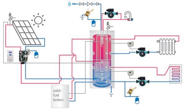
Page 86 Page 87 Highly-efficient INSU PRO insulation upon request for the models from 800 L to 1500 L. Combined buffer tanks with integrated enameled tanks (tank-in-tank) | with one heat exchanger | 600 L to 1500 L MODEL V 15 S 600 81 EV 150 40 C V 12 S 800 95 EV 200 45 C V 15 S 1000 95 EV 200 45 C V 12 S 1500 120 EV 300 55 C Art. number № 303866 303849 303876 303846 Capacity buffer tank L 416 579 666 1134 Capacity hot water tank L 151 191 191 296 Net weight kg 188 241 274 353 Insulation mm 100 100 100 100 Heat exchanger surface S1 m² 2.25 2.89 3.3 3.47 Heat exchanger capacity S1 L 13.7 26.2 29 31.4 Heat losses ∆T 45K W 116 128 136 158 Energy efficiency class C C C C Maximum operational temperature buffer tank ℃ 95 95 95 95 Maximum operational temperature hot water tank ℃ 95 95 95 95 Maximum operational temperature of heat exchanger ℃ 110 110 110 110 Rated pressure buffer tank bar 3 3 3 3 Rated pressure hot water tank bar 10 10 10 10 Rated pressure of the heat exchanger bar 6 6 6 6 INSTALLATION AND CONNECTION SCHEME Combined buffer tanks with integrated enameled tanks (tank-in-tank) | with one heat exchanger | 600 L to 1500 L MODEL V 15 S 600 81 EV 150 40 C V 12 S 800 95 EV 200 45 C V 15 S 1000 95 EV 200 45 C V 12 S 1500 120 EV 300 55 C CW cold water inlet G ½" B G 1" B G 1" B HW hot water outlet G ½" B G 1" B G 1" B IS1 heat exchanger inlet G 1" G 1½" B G 1½" B OS1 heat exchanger outlet G 1" G 1½" B G 1½" B Z recirculation G ½" B G ½" B G ½" B T thermometer Ø 14 x 1.5 Ø 14 x 1.5 Ø 14 x 1.5 TR opening for thermoregulator G ½" G ½" G ½" TS1-2-3-4 thermo sensor pocket levels 1-2-3-4 G ½" G ½" G ½" TSS1 thermo sensor pocket heat exchanger G ½" G ½" G ½" EE opening for electric element G 1½" G 1½" G 1½" AV opening for air ventilation G ½" G ½" G ½" L1-2-3-4 levels 1-2-3-4 G 1½" G 1½" G 2" B МА Magnesium anode 1 М8 М8 М8 Dimensions ±5 mm V 15 S 600 81 EV 150 40 C V 12 S 800 95 EV 200 45 C V 15 S 1000 95 EV 200 45 C V 12 S 1500 120 EV 300 55 C h mm 2065 1956 2141 2216 a mm 1747 1600 1795 1740 b mm 307 400 400 470 mm 934 1022 1187 1087 mm 289 362 362 427 n mm 489 582 582 647 o mm 130 150 150 150 q mm 1738 1502 1775 1726 r mm 1230 1122 1304 1293 s mm 722 742 833 860 t mm 214 362 362 427 w mm 22 22 22 22 x mm 110 100 100 110 z mm 100 100 100 100 R mm 2121 2045 2236 2238 Ø C mm 850 990 990 1200 Ø D mm 650 790 790 1000 Thread designations according to EN ISO 228-1! TS3 TS4 L1 L2 L3 L4 L1 L2 L3 L4 Ø D Ø C A r q a h s i t 0 j b 0 n TR T EE TSS1 IS1 OS1 TS1 TS2 R z o x w 45° 22.5° CW EE L1; 2; 3; 4 L1; 2; 3; 4 HW Z AV 90° view A MA

Page 88 Page 89 Combined buffer tanks with integrated enameled tanks (tank-in-tank) | without heat exchanger | 600 L to 1500 L MODEL V 600 81 EV 150 40 C V 800 95 EV 200 45 C V 1000 95 EV 200 45 C V 1500 120 EV 300 55 C Art. number № 303871 303874 303875 303869 Capacity buffer tank L 433 608 702 1170 Capacity hot water tank L 151 191 191 296 Net weight kg 161 193 220 295 Insulation mm 100 100 100 100 Heat losses ∆T 45K W 116 128 136 158 Energy efficiency class C C C C Maximum operational temperature buffer tank ℃ 95 95 95 95 Maximum operational temperature hot water tank ℃ 95 95 95 95 Rated pressure buffer tank bar 3 3 3 3 Rated pressure hot water tank bar 10 10 10 10 Highly-efficient INSU PRO insulation upon request for the models from 800 L to 1500 L. INSTALLATION AND CONNECTION SCHEME Combined buffer tanks with integrated enameled tanks (tank-in-tank) | without heat exchanger | 600 L to 1500 L MODEL V 600 81 EV 150 40 C V 800 95 EV 200 45 C V 1000 95 EV 200 45 C V 1500 120 EV 300 55 C CW cold water inlet G ½" B G 1" B G 1" B HW hot water outlet G ½" B G 1" B G 1" B Z recirculation G ½" B G ½" B G ½" B T thermometer Ø 14 x 1.5 Ø 14 x 1.5 Ø 14 x 1.5 TR opening for thermoregulator G ½" G ½" G ½" TS1-2-3-4 thermo sensor pocket levels 1-2-3-4 G ½" G ½" G ½" EE opening for electric element G 1½" G 1½" G 1½" AV opening for air ventilation G ½" G ½" G ½" L1-2-3-4 levels 1-2-3-4 G 1½" G 1½" G 2" B МА Magnesium anode 1 М8 М8 М8 Dimensions ±5 mm V 600 81 EV 150 40 C V 800 95 EV 200 45 C V 1000 95 EV 200 45 C V 1500 120 EV 300 55 C h mm 2065 1956 2141 2216 a mm 1747 1600 1795 1740 b mm 307 400 400 470 o mm 130 150 150 150 q mm 1738 1502 1775 1726 r mm 1230 1122 1304 1293 s mm 722 742 833 860 t mm 214 362 362 427 w mm 22 22 22 22 x mm 110 100 100 110 z mm 100 100 100 100 R mm 2121 2045 2236 2238 Ø C mm 850 990 990 1200 Ø D mm 650 790 790 1000 Thread designations according to EN ISO 228-1! A TS1 EE TS2 TS3 TS4 L1 L2 L3 L4 L1 L2 L3 L4 RØ D Ø C r q a h s t 0 b TR T z o x w 45° 22.5° CW EE L1; 2; 3; 4 L1; 2; 3; 4 HW Z AV 90° view A MA
BUFFER TANKS
WITH TWO, ONE AND WITHOUT HEAT EXCHNAGERS
3 Bar

BUFFER TANKS FOR HEATING SYSTEMS


A wide range of buffer tanks for operation in closed heating systems.


ADVANTAGES


The range includes models from 200 L to 2000 L with two, one or without heat exchangers: Advantages:


Heating buffer storage tank with four heat layers for various heating applications.
Four thermoprobe installation positions.
Highly efficient CFC free PU foam insulation for the models of 200 L to 500 L.
Highly efficient INSU PRO soft insulation upon request for the models from 800 L to 2000 L.


Heat exchangers with a larger surface.


All models with a hard PU foam insulation are suitable for active cooling applications.


Page 90 Page 91

Page 92 Page 93 Buffer tanks | with two heat exchangers | 400 L to 500 L MODEL V 11/5 S2 400 75 F42 P6 V15/7 S2 500 75 F42 P6 Art. number № 300613 300625 Capacity L 388 472 Net weight kg 140 149.5 Insulation (rigid PU) mm 50 50 Heat exchanger surface S1 m2 1.65 2.25 Heat exchanger surface S2 m2 0.76 1.04 Heat exchanger capacity S1 L 10 13.7 Heat exchanger capacity S2 L 4.6 6.4 Heat losses ∆T 45K W 91 95 Energy efficiency class C C Maximum operational temperature ℃ 95 95 Maximum operational temperature of heat exchanger ℃ 100 110 Rated pressure bar 3 3 Rated pressure of the heat exchanger bar 6 6 INSTALLATION AND CONNECTION SCHEME Buffer tanks | with two heat exchangers | 400 L to 500 L 90° 22.5° h Ø C Ø D t 0 u 0 g s r m e n q R D L1 TS2 TS1 L2 L3 TS3IS1 IS2 TSS1 TSS2 OS1 OS2 TS4 L4 L1 L2 L3 L4 AV Dimensions ±5 mm V 11/5 S2 400 75 F42 P6 V15/7 S2 500 75 F42 P6 h mm 1411 1674 e mm 1079 1349 g mm 864 1048 mm 781 934 mm 308 289 m mm 1002 1220 n mm 465 719 q mm 1166 1450 r mm 850 1038 s mm 534 626 t mm 218 214 u mm 68 67 R mm 1592 1826 Ø C mm 750 750 Ø D mm 650 650 for ALL MODELS IS1 heat exchanger inlet G 1" IS2 heat exchanger inlet G 1" OS1 heat exchanger outlet G 1" OS2 heat exchanger outlet G 1" TS1-2-3-4 thermo sensor pocket levels 1-2-3-4 G ½" TSS1 thermo sensor pocket heat exchanger G ½" TSS2 thermo sensor pocket heat exchanger G ½" AV opening for air ventilation G 1½" D drainage G ¾" L1-2-3-4 levels 1-2-3-4 G 1½" Thread designations according to EN ISO 228-1!

Page 94 Page 95 Buffer tanks | with two heat exchangers | 800 L to 2000 L MODEL V 12/9 S2 800 95 F43 P6 C V 15/9 S2 1000 95 C V 12/8 S2 1500 120 F45 P6 C V 15/9 S2 2000 130 F46 P6 C Art. number № 303891 303900 303890 303870 Capacity L 766 855 1415 1822 Net weight kg 191 206 308 405 Insulation mm 100 100 100 100 Heat exchanger surface S1 m2 2.89 3.45 3.47 4.5 Heat exchanger surface S2 m2 1.54 1.31 2.3 2.7 Heat exchanger capacity S1 L 26.2 31.3 31.4 41.6 Heat exchanger capacity S2 L 9.4 7.9 20.5 25.2 Heat losses ∆T 45K W 128 136 158 183 Energy efficiency class C C C C Maximum operational temperature ℃ 95 95 95 95 Maximum operational temperature of heat exchanger ℃ 110 110 110 110 Rated pressure bar 3 3 3 3 Rated pressure of the heat exchanger bar 6 6 6 6 Highly-efficient INSU PRO insulation upon request for the models from 800 L to 2000 L. INSTALLATION AND CONNECTION SCHEME 90° 22.5° m Ø C Ø D n r i s t 0 g q h e R TS1L1 TS2L2 L3 TS3 IS1 TSS1 OS1 TS4L4 L1 L2 L3 L4 AV IS2 TSS2 OS2 MODEL V 12/9 S2 800 95 F43 P6 C V 15/9 S2 1000 95 C V 12/8 S2 1500 120 F45 P6 C V 15/9 S2 2000 130 F46 P6 C IS1-2 heat exchangers inlet G 1½" B G 1½" B OS1-2 heat exchangers outlet G 1½" B G 1½" B TS1-2-3-4 thermo sensor pocket levels G ½" G ½" TSS1-2 thermo sensor pocket heat exchanger G ½" G ½" AV opening for air ventilation G 1½" G 2" B L1-2-3-4 levels 1-2-3-4 G 1½" G 2" B Thread designations according to EN ISO 228-1! Buffer tanks | with two heat exchangers | 800 L to 2000 L Dimensions ±5 mm V 12/9 S2 800 95 F43 P6 C V 15/9 S2 1000 95 C V 12/8 S2 1500 120 F45 P6 C V 15/9 S2 2000 130 F46 P6 C h mm 1947 2132 2220 2413 e mm 1500 1774 1726 1896 g mm 1120 1303 1293 1412 mm 1021 1186 1087 1271 m mm 1388 1501 1461 1565 n mm 581 581 647 646 q mm 1508 1746 1733 1903 r mm 1120 1360 1293 1412 s mm 740 832 860 929 t mm 360 360 427 446 R mm 1960 2155 2265 2481 Ø C mm 990 990 1200 1300 Ø D mm 790 790 1000 1100

Page 96 Page 97 Buffer tanks | with one heat exchanger | 200 L to 500 L MODEL V 9S 200 60 V 12S 300 65 V 11S 400 75 F42 P5 V 15S 500 75 F42 P5 Art. number № 302172 302173 300612 300624 Capacity L 195 283 394 480 Net weight kg 55 82 131 138 Insulation (rigid PU) mm 50 50 50 50 Heat exchanger surface S1 m2 0.96 1.45 1.65 2.25 Heat exchanger capacity S1 L 5.8 8.8 10 13.7 Heat losses ∆T 45K W 59 68 91 95 Energy efficiency class B B C C Maximum operational temperature ℃ 95 95 95 95 Maximum operational temperature of heat exchanger ℃ 110 110 110 110 Rated pressure bar 3 3 3 3 Rated pressure of the heat exchanger bar 6 6 6 6 INSTALLATION AND CONNECTION SCHEME 90° h Ø C Ø D t u 0 s r i n j q R D TS1L1 TS2L2 L3 TS3 IS1 TSS1 OS1 TS4L4 L1 L2 L3 L4 AV 22.5° Dimensions ±5 mm V 9S 200 60 V 12S 300 65 V 11S 400 75 F42 P5 V 15S 500 75 F42 P5 h mm 1202 1422 1406 1674 mm 655 817 780 719 mm 268 301 307 289 n mm 464 719 q mm 995 1208 1165 1450 r 730 873 849 1038 s mm 465 538 533 626 t 200 203 217 214 u mm 75 75 75 75 R mm 1343 1560 1590 1825 Ø C mm 600 650 750 750 Ø D mm 500 550 650 650 MODEL V 9S 200 60 V 12S 300 65 V 11S 400 75 F42 P5 V 15S 500 75 F42 P5 IS1 heat exchanger inlet G 1" G 1" OS1 heat exchanger outlet G 1" G 1" TS1-2-3-4 thermo sensor pocket levels 1-2-3-4 G ½" G ½" TSS1 thermo sensor pocket heat exchanger G ½" AV opening for air ventilation G 1½" G 1½" D drainage G ¾" B G ¾" B L1-2-3-4 levels 1-2-3-4 G 1½" G 1½" Thread designations according to EN ISO 228-1! Buffer tanks | with one heat exchanger | 200 L to 500 L

Page 98 Page 99 Buffer tanks | with one heat exchanger | 800 L to 2000 L MODEL V 12S 800 95 F43 P5 C V 15S 1000 95 C V 12S 1500 120 F45 P5 C V 15S 2000 130 F46 P5 C Art. number № 303889 303899 303887 303892 Capacity L 776 866 1439 1853 Net weight kg 169 198 265 360 Insulation mm 100 100 100 100 Heat exchanger surface S1 m2 2.89 3.45 3.47 4.5 Heat exchanger capacity S1 L 26.2 31.3 31.4 41.6 Heat losses ∆T 45K W 128 136 158 183 Energy efficiency class C C C C Maximum operational temperature ℃ 95 95 95 95 Maximum operational temperature of heat exchanger ℃ 110 110 110 110 Rated pressure bar 3 3 3 3 Rated pressure of the heat exchanger bar 6 6 6 6 Highly-efficient INSU PRO insulation upon request for the models from 800 L to 2000 L. INSTALLATION AND CONNECTION SCHEME 90° 22.5° h Ø C Ø D n r i s t 0 q R TS1L1 TS2L2 L3 TS3 IS1 TSS1 OS1 TS4L4 L1 L2 L3 L4 AV MODEL V 12S 800 95 F43 P5 C V 15S 1000 95 C V 12S 1500 120 F45 P5 C V 15S 2000 130 F46 P5 C IS1 heat exchanger inlet G 1½" B G 1½" B OS1 heat exchanger outlet G 1½" B G 1½" B TS1-2-3-4 thermo sensor pocket levels 1-2-3-4 G ½" G ½" TSS1 thermo sensor pocket heat exchanger G ½" G ½" AV opening for air ventilation G 1½" G 2" B L1-2-3-4 levels 1-2-3-4 G 1½" G 2" B Thread designations according to EN ISO 228-1! Buffer tanks | with one heat exchanger | 800 L to 2000 L Dimensions ±5 mm V 12S 800 95 F43 P5 C V 15S 1000 95 C V 12S 1500 120 F45 P5 C V 15S 2000 130 F46 P5 C h mm 1947 2132 2220 2413 mm 1021 1186 1087 1271 mm 360 360 427 446 n mm 581 581 647 646 q mm 1500 1774 1726 1896 mm 1120 1303 1293 1412 s mm 740 832 860 929 t mm 360 360 427 446 R mm 1960 2155 2265 2481 Ø C mm 990 990 1200 1300 Ø D mm 790 790 1000 1100
Buffer tanks

Page 100 Page 101 Buffer tanks | without heat exchanger | 200 L to 500 L MODEL V 200 60 F40 P4 V 300 65 F41 P4 V 400 75 F42 P4 V 500 75 F42 P4 Art. number № 300632 300634 300635 300636 Capacity L 202 294 406 497 Net weight kg 40 59 113.5 121 Insulation (rigid PU) mm 50 50 50 50 Heat losses ∆T 45K W 59 68 91 95 Energy efficiency class B B C C Maximum operational temperature ℃ 95 95 95 95 Rated pressure bar 3 3 3 3 INSTALLATION AND CONNECTION SCHEME section A-A section B-B A A u 0 t s r q h Ø DR Ø C φ AV D TS4 TS1 TS2 TS3 L4 L2 L1 L3 L4 L2 L1 L3 B B Dimensions ±5 mm V 200 60 F40 P4 V 300 65 F41 P4 V 400 75 F42 P4 V 500 75 F42 P4 h mm 1200 1420 1410 1674 q mm 993 1208 1165 1451 r mm 728 873 849 1039 s mm 463 538 533 627 t mm 198 203 217 215 u mm 50 52 67 67 φ ° 45 45 22.5 22.5 R mm 1345 1563 1590 1823 Ø C mm 600 650 750 750 Ø D mm 500 550 650 650 for ALL MODELS TS1 thermo sensor pocket level 1 G ½" TS2 thermo sensor pocket level 2 G ½" TS3 thermo sensor pocket level 3 G ½" TS4 thermo sensor pocket level 4 G ½" AV opening for air ventilation G 1½" D drainage G ¾" L1 level 1 G 1½" L2 level 2 G 1½" L3 level 3 G 1½" L4 level 4 G 1½" Thread designations according to EN ISO 228-1!
| without heat exchanger | 200 L to 500 L
Buffer
Page 102 Page 103 Buffer tanks | without heat exchanger | 800 L to 2000 L MODEL V 800 95 F43 P4 C V 1000 95 C V 1500 120 F45 P4 C V 2000 130 F46 P4 C Art. number № 303896 303897 303893 303894 Capacity L 805 902 1476 1904 Net weight kg 115 145 210 284 Insulation mm 100 100 100 100 Heat losses ∆T 45K W 128 136 158 183 Energy efficiency class C C C C Maximum operational temperature ℃ 95 95 95 95 Rated pressure bar 3 3 3 3 Highly-efficient INSU PRO insulation upon request for the models from 800 L to 2000 L. INSTALLATION AND CONNECTION SCHEME 90° 22.5° h Ø C Ø D s r t 0 q R TS1L1 TS2L2 L3 TS3 TS4L4 L1 L2 L3 L4 AV Dimensions ±5 mm V 800 95 F43 P4 C V 1000 95 C V 1500 120 F45 P4 C V 2000 130 F46 P4 C h mm 1947 2132 2220 2413 q mm 1500 1774 1726 1896 r mm 1120 1303 1293 1412 s mm 740 832 860 929 t mm 360 360 427 446 R mm 1960 2155 2265 2481 Ø C mm 990 990 1200 1300 Ø D mm 790 790 1000 1100 MODEL V 800 95 F43 P4 C V 1000 95 C V 1500 120 F45 P4 C V 2000 30 F46 P4 C TS1 thermo sensor pocket level 1 G ½" G ½" TS2 thermo sensor pocket level 2 G ½" G ½" TS3 thermo sensor pocket level 3 G ½" G ½" TS4 thermo sensor pocket level 4 G ½" G ½" AV opening for air ventilation G 1½" G 2" B L1 level 1 G 1½" G 2" B L2 level 2 G 1½" G 2" B L3 level 3 G 1½" G 2" B L4 level 4 G 1½" G 2" B Thread designations according to EN ISO 228-1!
tanks | without heat exchanger | 800 L to 2000 L
BUFFER TANKS WITH ANTICONDENSE SOLUTION
ADVANTAGES
3 Bar
BUFFER TANKS FOR HEAT PUMP SYSTEMS
Buffer tanks specifically developed for integration in heat pump systems.

The range includes models of 100 L, 160 L and 200 L without heat exchanger for wall or floor installation.


Advantages:

High-density CFC PU insulation for low energy losses. 4 inlets and 4 outlets with a G 1.1/2“ for a higher flow rate.
High energy efficiency class A (100 L) model and class B (other models). Stratification brackets on all the inlets and outlets.
Drainage on G ¾”. AV opening. Rated pressure 3 bar.
Anti-condense insulation on the fittings. 2 pockets for thermosensors (1 for the 100 l model).
Page 104 Page 105
Page 106 Page 107 Buffer tanks for heat pump systems | without heat exchangers | 100 L MODEL V 100 55 ACF Art. number № 305412 Capacity L 101 Net weight kg 34 Insulation (rigid PU) mm 73 Heat losses ∆T 45K W 34 Energy efficiency class A Maximum operational temperature ℃ 95 Rated pressure bar 3 INSTALLATION AND CONNECTION SCHEME AV D L4 L3 L2 L1 L4 TS1 L1 L2 L3 0 t s r q h R Ø C Ø D TS145 ° 294 Buffer tanks for heat pump systems | without heat exchangers | 100 L Dimensions ±5 mm V 100 55 ACF h mm 932 q mm 710 r mm 550 s mm 390 t mm 230 u mm R mm 1081 Ø C mm 550 Ø D mm 404 MODEL V 100 55 ACF TS1 thermo sensor pocket level 1 G ½" AV opening for air ventilation G ¾" D drainage G ¾" L1 level 1 G 1½" L2 level 2 G 1½" L3 level 3 G 1½" L4 level 4 G 1½" Thread designations according to EN ISO 228-1!
Page 108 Page 109 Buffer tanks for heat pump systems | without heat exchangers | 160 L to 200 L MODEL V 160 60 ACF V 200 60 ACF Art. number № 305413 305414 Capacity L 163 202 Net weight kg 40 44 Insulation (rigid PU) mm 50 50 Heat losses ∆T 45K W 49 56 Energy efficiency class B B Maximum operational temperature ℃ 95 95 Rated pressure bar 3 3 INSTALLATION AND CONNECTION SCHEME 0 u t s r q h R Ø C Ø D L1L1 L2L2 L3L3 L4L4 AV D TS1 TS2 90 ° 22.5°TS1,2 L1,2,3,4L1,2,3,4 Buffer tanks for heat pump systems | without heat exchangers | 160 L to 200 L Dimensions ±5 mm V 160 60 ACF V 200 60 ACF h mm 1007 1202 q mm 779 995 r mm 586 730 s mm 393 465 t mm 200 200 u mm 75 75 R mm 1169 1343 Ø C mm 600 600 Ø D mm 500 500 for ALL MODELS TS1 thermo sensor pocket level 1 G ½" TS2 thermo sensor pocket level 2 G ½" AV opening for air ventilation G 1½" D drainage G ¾" B L1 level 1 G 1½" L2 level 2 G 1½" L3 level 3 G 1½" L4 level 4 G 1½" Thread designations according to EN ISO 228-1!
BUFFER TANKS
FOR HEAT PUMP SYSTEMS
ADVANTAGES
6 Bar
NON-ENAMELED BUFFER TANKS FOR HEAT PUMP SYSTEMS

The range includes models of 50 L and 80 L without a heat exchanger for wall installation.


Advantages:


High-density 50 mm PU insulation for low energy losses. 4 inlets and 4 outlets with a G 1.1/4“ for a higher flow rate.


High energy efficiency class B.
Stratification brackets on the lower and bottom inlets and outlets.


Drainage on G 1½”.
Air ventilation on G ¾”.
Rated pressure 6 bar.
Page 110 Page 111
Page 112 Page 113 Buffer tanks for heat pump systems | 50 L to 80 L MODEL V 50 40 V 80 46 Art.number № 423103 423100 Capacity L 51 80 Net weight kg 23.2 35 Insulation (rigid PU) mm 50 50 Heat losses ∆T45K W 38 45 Energy efficiency class B B Maximum operational temperature °C 95 95 Rated pressure bar 6 6 INSTALLATION AND CONNECTION SCHEME Buffer tanks for heat pump systems | 50 L to 80 L AV AV D L4 L3 L2 L1 L1,2,3,4 L4 L1 L1,2,3,4 L2 L3 0 t s r 985 / 1054 q h R C D Dimensions ±5 mm V 50 40 V 80 46 h mm 865 915 q mm 718 742 r mm 528 552 s mm 338 362 t mm 148 172 R mm 953 1003 ØC mm 400 460 ØD mm 300 360 for ALL MODELS Opening for air ventilation G ¾" Drainage G 1½" Level 1 G 1¼" Level 2 G 1¼" Level 3 G 1¼" Level 4 G 1¼" Thread designations according to EN ISO 228-1!
SOLAR ENERGY SYSTEMS
ADVANTAGES
SOLAR ENERGY SYSTEMS

Advantages:
Electric energy hot water system.
Directly heated by by sun radiation.
High-density PU insulation of the water tank.
Rockwool insulation of the solar panel.
Stand for flat and sloping roofs available.
A complete connection kit included in the set.
Solar Keymark certified.
Flow box.
Solar controller.
Page 114 Page 115
Solar energy systems


Solar
systems
1
x
x Nipple Ø 22 -
x Nipple Ø 22 - Ø
MK-SR/FR-SP08
Manual
x Cap 22 mm


vent
x Nipple Ø 22 - ¾"
x Nipple Ø 22 - Ø 22
Manual air vent 2 x Cap 22mm 1 x Nipple Ø 22 - ¾" 2 x Nipple Ø 22 - Ø 22

x Flexible hose 4 x Nipple Ø 22 - 1"


Page 116 Page 117 H L W SP 08 200 CSL - Pressure drop Pressure drop, [Pa] Mass flowrate, [kg/s] 800 600 200 400 0 0 -200 0.03 0.06 0.09 0.12 SP 08 260 CSL - Pressure drop Pressure drop, [Pa] Mass flowrate, [kg/s] 1200 900 300 600 0 0 -300 0.03 0.06 0.09 0.12 SP 08 200 CSL - Pressure drop SP 08 260 CSL - Pressure drop Pressure drop, [Pa] Pressure drop, [Pa] MODEL SP 08 200 CSL SP 08 260 CSL Art. number 421600 421602 Absorber area m² 1.8 2.37 Weight empty kg 36.5 45 Coating selective selective Absorption ratio % 95 95 Reflection capacity % 5 5 Max. operating pressure bar 10 10 Number of risers pieces 8 11 Heat carrier propylene-glycol solution propylene-glycol solution Absorber capacity L 1.28 1.64 Attachment connections mm Ø 22 Ø 22 Collector efficiency (absorber) % 77 78 Heat loss linear ratio а₁ W/m²K 3.95 3.77 Heat loss square ratio а₂ W/m²K² 0.016 0.015 Dimensions L mm 2030 2030 W mm 1030 1280 H mm 80 80
| Flat plate solar collectors with a selective absorber | Aluminium absorber
energy
| Complete solar systems | Solo system MODEL SS 150 SP08 SS 200 SP08 SS 300 SP08 SS 500-6 SP08 Art. number № 301673 301675 301676 301677 Number of people served 2-3 3-4 4-5 6-7 Maximum available amount of hot water L 147 225 330 553 Solar panel type 1 x SP 08 200 CSL 2 x SP 08 200 CSL 2 x SP08 200 CSL 3 x SP08 200 CSL Solar storage tank model EU GCV9S 150 44 20 B11 TSRP EV 7/5S2 200 60 F40 TP2 EV 10/7S2 300 65 F41 TP2 EV 15/7S2 500 75 F42 TP2 Pump group model FlowBox 8010-S FlowBox 8010-S FlowBox 8010-S FlowBox 8010-E Expansion vessel S12L S12L S12L S24L Controller model RS02P RS02P RS02P ECOSOL-E Propylene glycol - 5 L pieces 1 2 3 3 Solar stand 1 x МК-SR/FR-SP08 1 x MK-SR/FR-SP08 200 Double
x
200 Double 1 x МК-SR/FR-SP08 1 x MK-SR/FR-SP08 200 Double Input-output connections 1 x Manual air vent 2 x Cap 22 mm 1 x Nipple Ø 22 - ¾" 1 x Manual air vent 2
Cap 22 mm 1
¾" 2
22 1 x
air
2
1
2
1 x
2
Package set dimensions (L x W x H) mm 820 x 1280 x 2460 820 x 1280 x 2460 1200 x 1280 x 2460 1200 x 1280 x 2460 All systems are designed for latitude between ~ 35°N to 50°N and altitude between ~ 0 m to 1000 m! For more details about system design, please refer to instruction manual!
system
Accessories | Solar energy system
NAME Art. №
Solar pump group
Dimensions, mm
Max. working pressure, bar
Max. working temperature, ℃
Debit range, L/ min Description
FlowBox Solar FSB8010-S 420103 308x270x220 10 110 2-17
thermal installations
solar
circulation pumps, and/or diverter


storage
integrative
In addition to the basic function of temperature differential regulator, it features numerous options to manage plant layouts of various complexities and to optimise the overall performance of the plant; it allows the achievement of considerable energy savings thanks to the ability to drive pumps with high efficiency and to manage flow sensors. - universal power supply - graphic backlit LCD - two-colour LED for diagnostics/signalling - 3 touch keys with sound feedback - 4 inputs for PT1000 or NTC probes - 1 input for flow meter - 4 relay outputs of which 2 PWM outputs - SELV insulation - it can be installed on the wall or in an electric control panel

Programmable digital controller for solar thermal systems equipped with a solar collector, a high-efficiency circulation pump, a storage tank and heating support. Besides its basic function of temperature differential regulator, this device is able to optimise the solar thermal system performance thanks to the possibility to drive a PWM modulating pump, and it also offers several functions for the system protection. Its features, as well as its simple design and userfriendly interface, make this product suitable for different types of solar thermal systems. - 2-digit 7-segment display - 3 diagnostics/signalling LEDs - 3 set-up keys - 3 inputs for probes type PT1000 or NTC (10K@25℃ b=3435 or 1,65K@80℃ b=3530) - 3 outputs: - 1 (power-free contact) N.O. relay output - 1 (12 VDC) PWM output + 1 associated (mains voltage) N.O. relay output - insulation type SELV (Safety Extra Low Voltage) - possible installation on a wall or on an electric control panel
FlowBox Solar

308x250x200 10 110 4-36
Ready-to-install, compact solar return. Pump installation length 130 mm - wired ex-works, balancing valve WattFlow with fill and drain cook, safety unit with a pressure gauge, solar safety relief valve 6 bar and a fill and drain cook, wall bracket including a corrugated tube to connect with an expansion vessel with an arrangeable metal gravity flow stop, heat insulation, compression fitting connection 22 mm.
Ready-to-install, compact solar control unit. Pump installation length 130 mm - wired ex works, balancing valve WattFlow with fill and drain cook, safety unit with a pressure gauge, solar safety relief valve 6 bar and a fill and drain cook, wall bracket including corrugated tube to connect with the expansion vessel with an anarrangeable metal gravity flow stop, EPP heat insulation, venting pipe, compression fitting connection 22 mm.
Connector


Page 118 Page 119 Accessories | Solar energy system NAME Art. № Expansion vessel - in conformity with Pressure equipment directive 2014/68/EU (PED), module H1 Capacity, L Height, mm Connection Max working pressure, bar Max working temperature, ℃ S 12 L 421170 12 350 ¾" 10 130 S 24 L 421171 Solar controller - Digital control system for the management of solar heat plant: Width, mm Height, mm Depht, mm Description ECOSOL-E 422366 110 163 52 Programmable digital control
for solar
including
collectors,
valves,
tanks and
heating.
PT1000 NTC RS02P 422364 100 70 36
PT1000 NTC
FSB8010-E 422365
and fitting for solar collector Connection Blind plug Ø 22 420100 Ø 22 Nipple Ø 22 - Ø 22 420099 Ø 22 - Ø 22 Connection kit for one solar collector Connection Set Nipple NP-22-¾" (Ø 22 - ¾") 300839 Ø 22 - G¾" 1 pcs Blind plug Ø 22 Ø 22 2 pcs Manual air valve with sensor hive SH-22 Ø 22 - ¾" 1 pcs Flexible house kit FH-22 for solar panels Connection Set Flexible hose 50 mm 300877 1" 2 pcs Nipple NP-22-1" Ø 22 - 1" 4 pcs
Electric sets (sold separately):
heating
From 160 L to 500 L
3 kW E Water heating set 3 kW plug and play (from 160 L to 500 L) 301456
3 kW Water heater set 3 kW (from 160 L to 500 L) 301455
Package includes: pos.2 rubber gasket pos.3 flange G 1½" pos.7 HE 3000 W / 230 V, with thermostat + thermal cut-off 70 ±5℃ / 85 ±5℃ with plug (MB3000 ORW1_230V-64)
Package includes: pos.2 rubber gasket pos.3 flange G 1½" pos.7 HE 3000 W / 230 V 3 phase, L= 290 pos.9 thermostat + thermal cut out with thermo pocket (160 L up to 500 L)
Accessories | Immersion heating element
From 800 L to 2000 L
4.5 kW Water heater set 4.5 kW (from 160 L to 500 L) 301457
Package includes: pos.2 rubber gasket pos.3 flange G 1½" pos.7 HE 4500 W / 230 V 3 phase, L= 405 pos.9 thermostat + thermal cut out with thermo pocket (160 L up to 500 L)
6 kW Water heater set 6 kW (from 160 L to 500 L) 305620
4.5 kW Water heater set 4.5 kW (from 800 L to 2000 L) 300560
6 kW Water heater set 6 kW (from 800 L to 2000 L) 300562
Package includes: pos.2 rubber gasket pos.3 flange G 1½" pos.7 HE 6000 W / 230 V 3 phase, L= 440 pos.9 thermostat + thermal cut out with thermo pocket (160 L up to 500 L)
Package includes: pos.7 HE 4500 W / 230 V 3 phase, L= 405 pos.9 thermostat + thermal cut out with thermo pocket (750 L up to 2000 L)
Package includes: pos.7 HE 6000 W / 230 V 3 phase, L= 505 pos.9 thermostat + thermal cut
Heating elements with integrated thermostat (sold separately)
From 160 L to 500 L
From 800 L to 2000 L
From 120 L to 160 L
Indirectly heated water tanks under gas boliers
(form 800 up to 2000 L)
Electrical heat resistance 3kW (from 160 L to 500 L) 305558 HE 3000W/230V 3 phase, L= 290mm
Electrical heat resistance 4.5kW (from 160 L to 500 L) 305364 HE 4500W/230V 3 phase, L= 405mm
Electrical heat resistance 6kW (from 160 L to 500 L) 305365 HE 6000W/230V 3 phase, L= 440mm
Electrical heat resistance 6kW (from 800 L to 2000 L) 305365 HE 6000W/230V 3 phase, L= 505mm
Electrical heat resistance 7.5kW (from 800 L to 2000 L) 305366 HE 7500W/400V 3 phase, L= 615mm
Electrical heat resistance UGT 3kW (from 160 L to 500 L) 305619 HE 3000W/230V 3 phase, L= 700mm
Page 122 Page 123 MODEL Power Name Art. № Description
out with thermo pocket (750 L up to 2000 L) 7.5 kW Water heater set 7.5 kW (from 800 L to 2000 L) 300564 Package includes: pos.7 HE 7500 W / 400 V 3 phase, L= 615 pos.9 thermostat + thermal cut-off with thermo pocket (750 L up to 2000 L) 12 kW Electrical heat set 12 kW 2” (from 800 L to 2000 L) 304313 Package includes: pos.7 HE 12000 W / 400 V 3 phase, L=520, G2" pos.9 thermostat + thermal cut out with thermo pocket (750 L up to 2000 L) Accessories | Immersion
element MODEL Power Name Art. № Description Flange with a fitting for heating element (sold separately) From 800 L to 2000 L 3 kW Flange cover set 1 HE (from 800 L to 2000 L) 305496 Package includes: pos.2 rubber gasket pos.3 cover flange with fitting G 1½” 4.5 kW 6 kW 7.5 kW From 800 L to 2000 L 12 kW Flange cover set 1 HE (from 800 L to 2000 L) 305497 Package includes: pos.2 rubber gasket pos.3 cover flange with fitting G2” Flange with 2 fittings for heating elements (sold separately): From 800 L to 2000 L 3 kW Flange cover set 2 HE (from 800 L to 2000 L) 305561 Package includes: pos.2 rubber gasket pos.3 cover flange with two fittings 2xG1½” 4.5 kW 6 kW 1 2 3 4 5 6 7 89 9 7 MODEL Power Name Art. № Description Heating elements (sold separately): From 160 L to 500 L 3 kW Plug and play electric heating element 300910 Electric heating element 3000 W / 230 V 3 kW Electric heating element 3 kW (from 160 L to 500 L) 300570 HE 3000 W / 230 V 3 phase, L= 290 4.5 kW Electric heating element 4.5 kW (from 160 L to 2000 L) 300571 HE 4500 W / 230 V 3 phase, L= 405 6 kW Electric heating element 6 kW (from 160 L to 500 L) 305618 HE 6000 W / 230 V 3 phase, L= 440 Combined temperature control unit 300592 Thermostat + thermal cut out with thermo pocket (form 160 up to 500 L) From 800 L to 2000 L 6 kW Electric heating element 6 kW (from 800 L to 2000 L) 300573 HE 6000 W / 230 V 3 phase, L= 505 7.5 kW Electric heating element 7.5 kW (from 800 L to 2000 L) 300575 HE 7500 W / 400 V 3 phase, L= 615 12 kW Electric heating element 12 kW (from 800 L to 2000 L) 300569 HE 12000 W / 400 V 3 phase, L= 520 Combined temperature control unit 300593 Thermostat + thermal cut out with thermo pocket
:
3kW
4.5kW
6kW
6kW
7.5kW
3kW


Page 124 Page 125 Accessories | Flanges fitted in TESY storage tanks Flange type Applicable for tanks with volume DN 120 From 160 L to 500 L DN 180 From 800 L to 2000 L DN 400 From 1000 L to 2000 L DN 400 DN 120 Ø120 8 x M10 Ø178 Ø15045° Ø176 12 x Ø11 30° Ø274 Ø232 495 Ø390 Ø480 26 x Ø13 Ø445 13.8° DN 180 176 257 36° 225 10 Ø11 DN 180 DN 180 Accessories | Buffer tanks for heat pump systems NAME Art. № Buff er tanks for Heat Pump Systems Description ACS Buffers AC 303580 Set of 6 plastic caps with K-flex and anti-moisture ACS PLUG HEX ACF 100-200L 305424 6 pcs metal plugs G1.1/2” ACS THERMOSET ACF 100-200L 305425 2 pcs brass sleeves for the thermopockets
Tesy Ltd. Sofia Park, Building 16 V, 2nd Floor 1166 Sofia, Bulgaria www.tesy.com This catalogue is a marketing material and it is not an offer. For specific models, please contact your dealer. Copyright © All Rights Reserved, v. 1 2021 – TESY Ltd.
