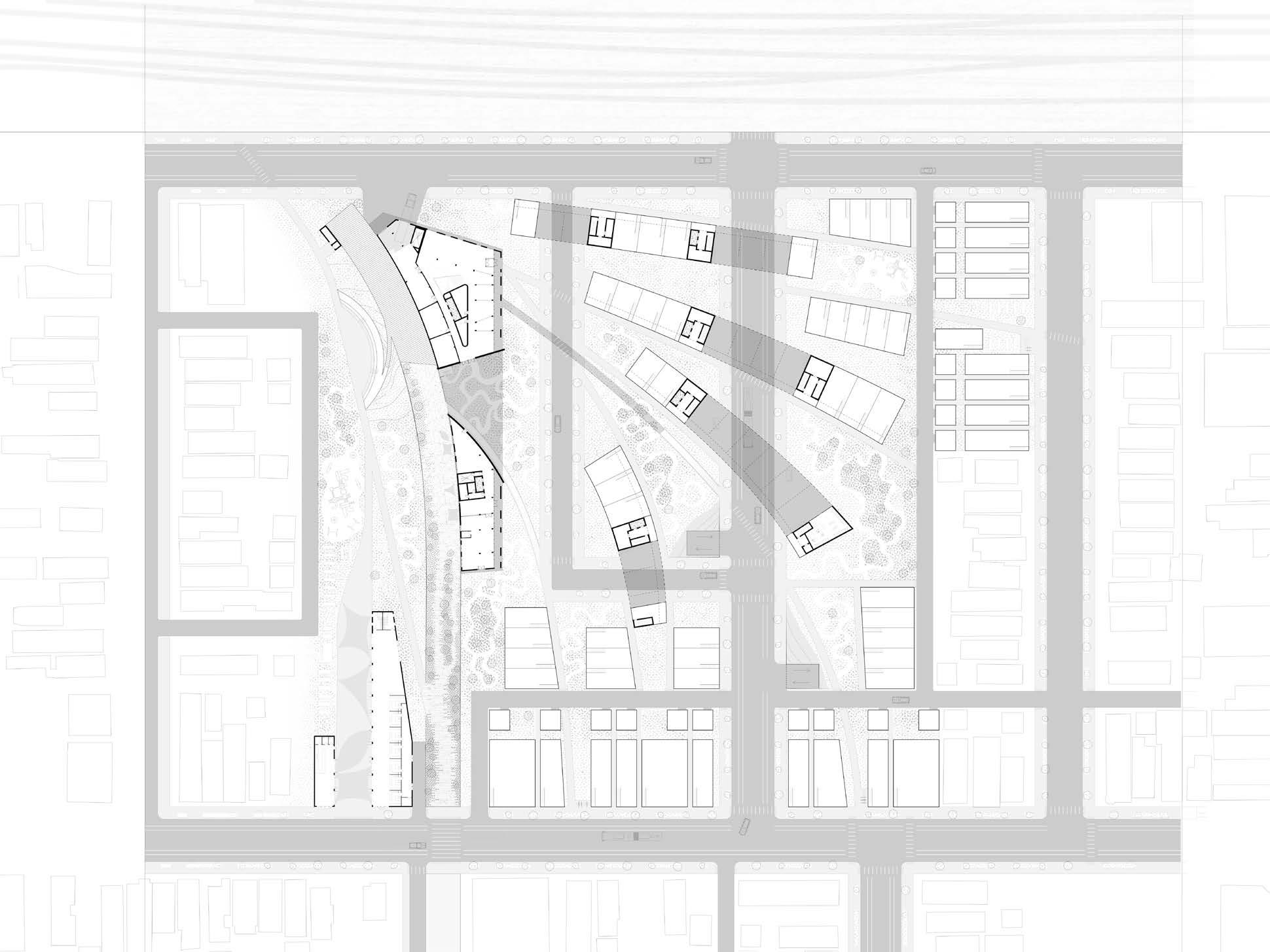
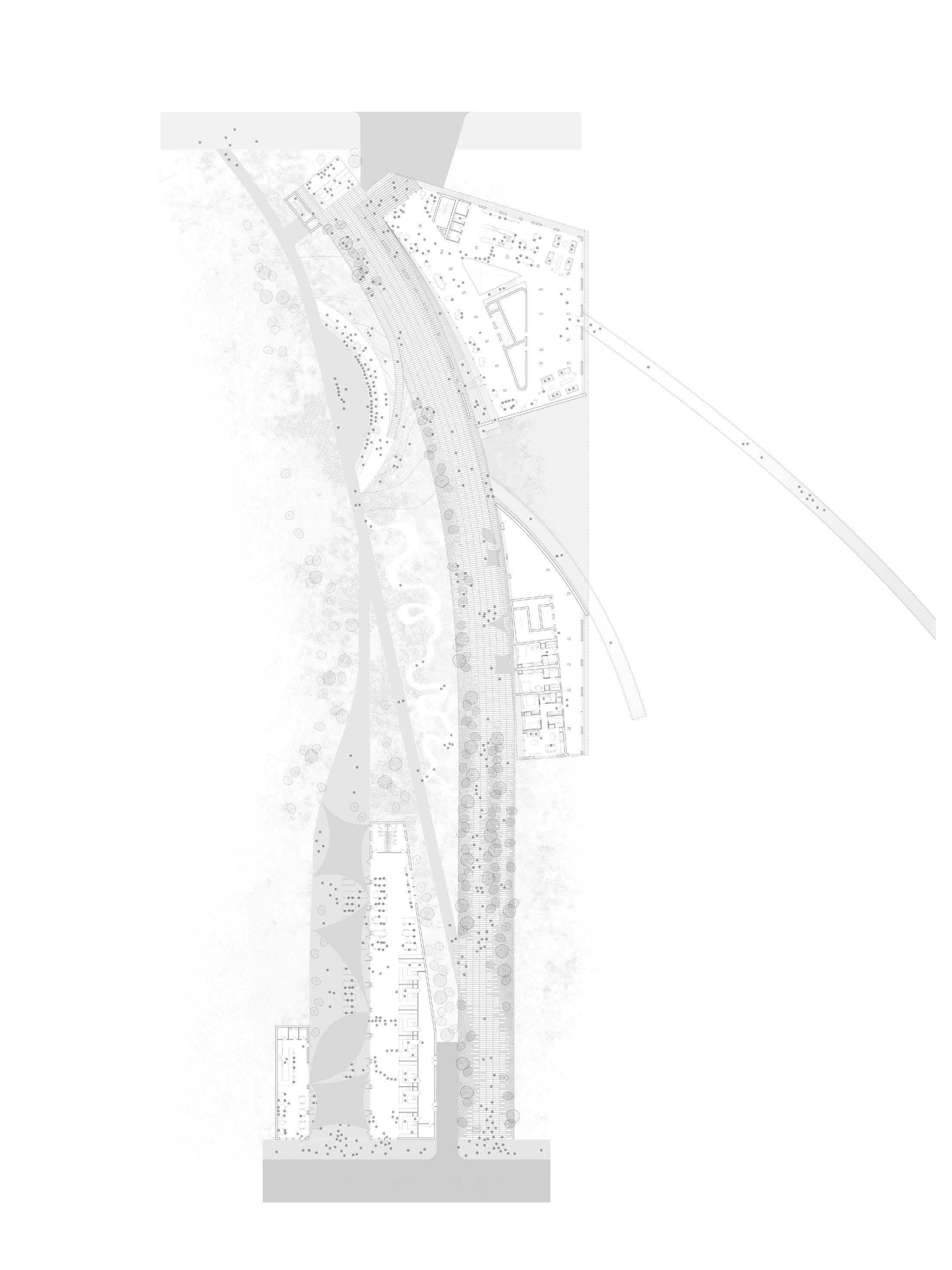
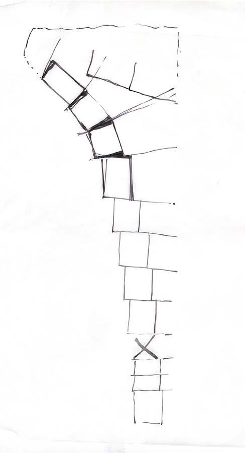
El Paseo site plan
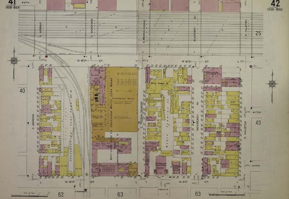
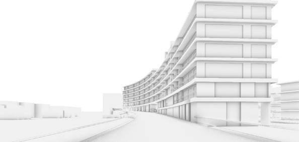
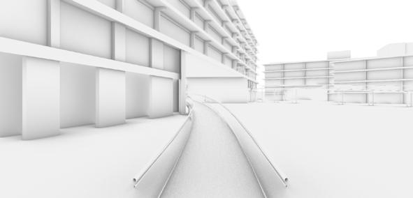
A 4.2 mile long trail called the El Paseo travels from the northern boundary of Pilsen down south and into Little Village. The proposed development was historically a Burlington Quincy and Chicago rail line that transported goods to and fro between Chicago and the Illinois river.
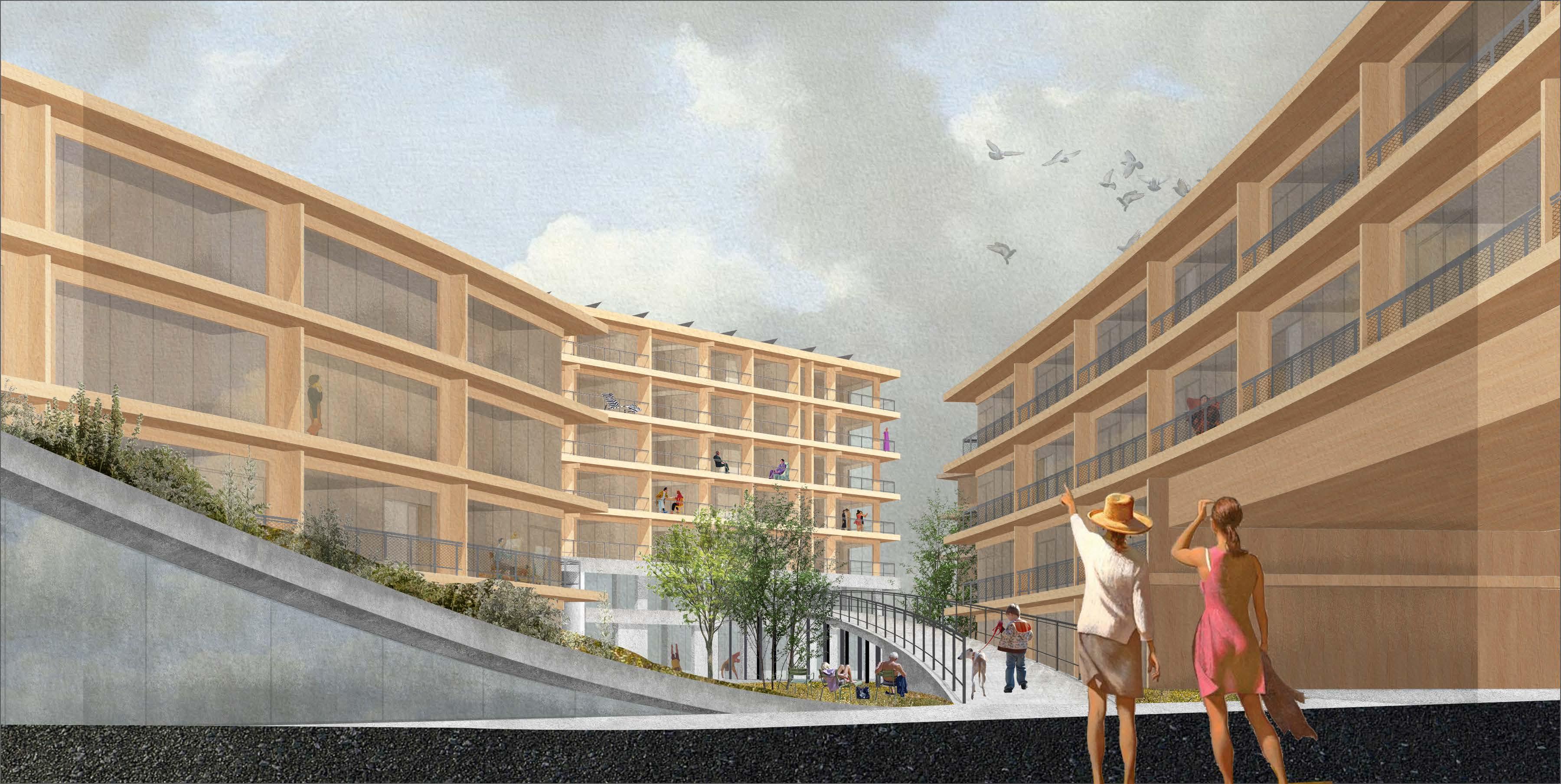
The El Paseo has many recreational programmatic uses such as food markets, an outdoor amphitheater, observation deck and many more. Pavers are arrayed along the curve of the El Paseo to pay homage to previous rail lines and vegetation is woven through the landscape.
(C) Food market
(B) Amphitheater
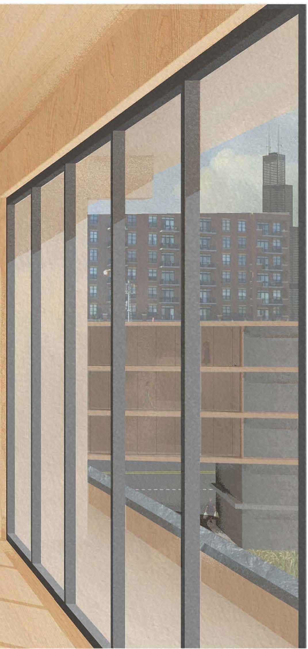
(A) Cafe and observation stair
(C)
(B)
(A)
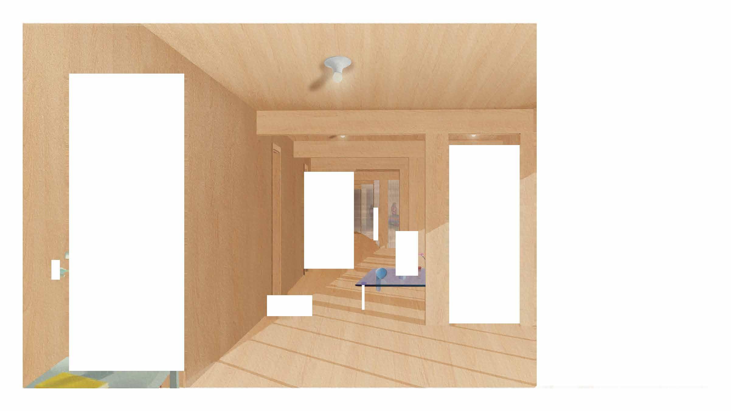
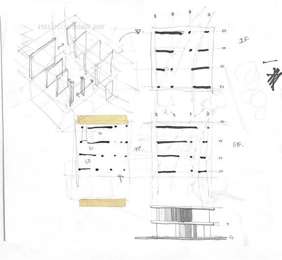
Floor plans
Ground floor plan (left)
The building is divided into a more public lobby in the north and a more private entrance for residents on the south. The public lobby has a social stair and atrium along with at home office spaces. The daycare and mail room are located in the south.
2nd floor plan (middle)
The cafe space on the north opens onto the El Paseo encouraging foot traffic between the two.
Typical floor plan (right)
Residential units are arrayed along the El Paseo. Additional amenities are provided in the lower wing of the building. It is a library on this particular floor.
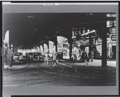
TRACK CREWS REPAIRING TRACKS IN THE ROUNDHOUSE AT AN ILLINOIS RAILROAD YARD, 1942
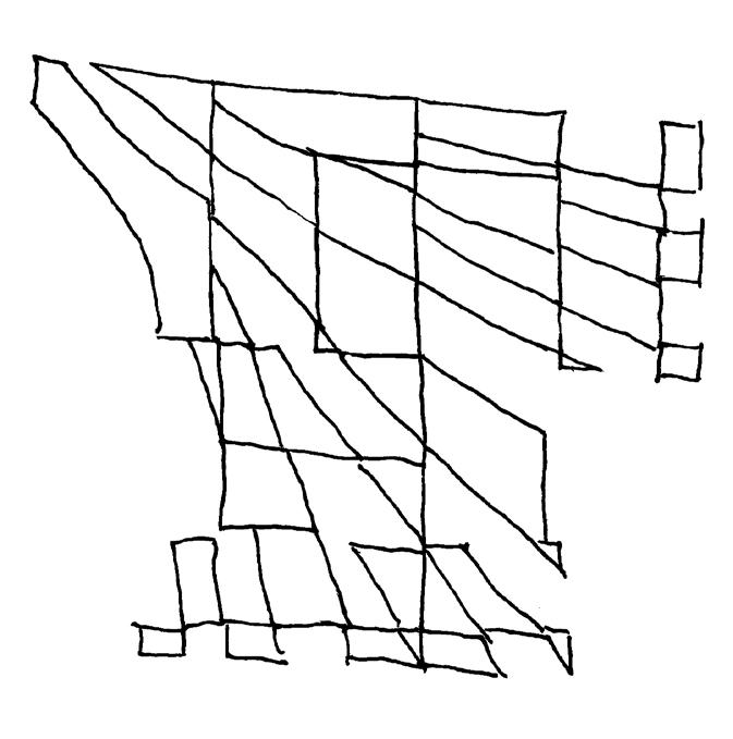
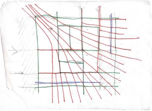
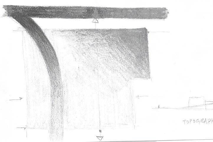
Concept to design
Structural plans
Ground floor structural (left)
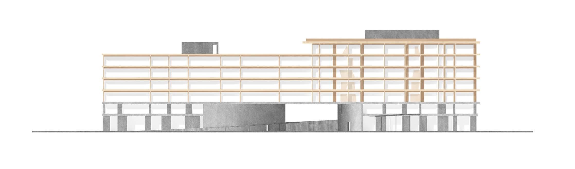
Concrete columns and walls are located at points on the CLT shear walls above. All cores are concrete throughout the height of the structure. A concrete retaining wall is build along the west side of the building for the elevated outdoor area.
Typical floor structural (right)
CLT honeycomb structure is used with shear walls, beams and columns. Spans are no longer than 25’ apart. No shea wall is narrower than 2’ at its widest.
Studio 1 Bed
Bed
All ADA units are compliant with a 60" diameter turning radius, and or a 36" wide T-turning junction and accessible bathrooms. Showers have built-in seats and grab bars for support.
Sprinkler system is divided into two zones. Sprinkler lines are laid on either side of the CLT wall panel in-between units and punch through CNC routed cutouts to reach the other unit. Ceiling mounted sprinklers are used in areas with a dropped ceiling while wall mounted sprinklers are used in other spaces.
Stairwells are located within 50 feet of a dead end corridor. Egress path shown is 107ft long.
Code and Zoning Matrix
1.10 Setbacks
a) Minimum Front Setback
b) Other Setbacks 17-02-0309-A buildings covering more than 50% of the
Basement
Exterior Structural Members
Max
14B-7-704.10
Parapets
14B-7-705.11
14B-7-712
Components 14B-10-1005.3.2 means of egress components other than stairways shall be calculated by = (occupant load) * (means of egress capacity factor of 0.2" per occupant)
c) Doors 14B-10-1010.1.1 means of egress doors shall not be concealed by ccurtains, drapes, decorations or similar materials minimum clear opening of 32" maximum width of swinging door leave is 48" minimum clear opening height of doors shall not be less than 80" projections into the required clear opening width may not be lower than 34" and shall not exceed 4" 36" egress door width, compliant
Swing of Doors 14B-10-1010.1.2.1 swing in direction of egress travel when serving a room or area with occupant load of 50 or more compliant Landing length at doors
14B-10-1010.1.6 landings shall have a width not less than the width of the stairway or the door, whichever is greater landing length in the direction of travel in Groups R3 or R-5 and within individual units of R-2 need not exceed 36"
3' 10", compliant
Hardware 14B-10-1010.1.9 hardware shall not require tight grasping, tight pinching, or twisting of wrist to operate hardware height shall be installed 34" minimum and 48" maximum above the finished door compliant
Revolving Doors
Electrically Locked Egress
14B-10-1010.1.4.1 each revolving door shall be capable of break out provide an aggregate width of not less than 36" shall not be located within 10' of the foot or top of stairways or escalators emergency stop switch shall have a side-hinged swinging door in the same wall and within 10' of revolving door revolving doors are not part of an accessible route compliant
14B-10-1010.1.9.7 door locks shall unluck on actuation of the automatic sprinkler system or automatic fire detection system a building occupant shall not be required to pass through more than one door equipped with a controlled egress locking system before entering an exit emergency lighting shall be provided at the door compliant
Panic Hardware Required 14B-10-1010.1.10 on a lot containing buildings with 5 or more stories above grade plane or containing 5 or more dwelling units or sleeping units, an exterior gate shall not require a key or special tool to operate in direction of egress. compliant
Stairways
a) Headroom 14B-10-1011.3 always have a clearance of not less than 7', this shall be continuous above the stairway to the point where the line intersects the landing below, one tread depth beyond the bottom riser. the minimum clearance shall be maintained the full width of the stairway and landing compliant
b) Tread and Risers 14B-10-1011.5 all dimensions are exclusive of carpets, rugs, or runners for R-5 occupancies and within dwelling units of R-2: riser heights shall be 8" maximum and 4" minimum tread depths shall be 9" minimum stair tread and risers shall be of uniform size and shape
7" riser, 11" tread, compliant
c) Stairway Landings
b) Handrail location required
e) Stair to roof and elevator equipment
14B-10-1011.6 there shall be a floor or landing at the top and bottom of each stairway the width of landings measures perpendicularly to the direction of travel shall be no less than the width of stairways served every landing shall have a minimum depth of 48" or the width of the stairway, whichever is less. door opening onto a landing shall not reduce the landing by more than 1/4 the req width wheelshair space shall not be located in teh req. width of the landing, doors shall not swing over the wheelchair space 48" width, compliant
14B-10-1011.11 shall return to a wall, guard, or walking surface or be continuous to the handrail of an adjacent flight of stairs or ramp run. compliant
14B-10-1011.12 buildings 4+ stories above grade must have 1 stairway extending to the roof surface a roof containing elevator equipment that must be accessed for maintenance required to be accessed by a stairway north core extend to floor 7, compliant
f) Ship's ladder
g) Ladders
Handrails
a) Height
14B-10-1011.15 ship ladders permitted to be used in group I-3 as a component of a means of egress to and from control rooms or elevated facility observation stations not more than 250 sf with not more than 3 occupants handrails provided on both sides of ship's ladders shall have a minimum tread depth of 5in and tread shall project so that total of tread depth plus nosing projection is no less than 8.5 inches. the maximum riser height shall be 9.5 inches N/A
14B-10-1011.16 permanent ladders shall not serve as a part of the means of egress from occupied spaces within a building N/A
14B-10-1014.2 height measured above stair tread nosings or finish surace of ramp slop shall be no less than 34 inches and not more than 38 inches compliant
b) Extensions 14B-10-1014.6 where the handrail is not continuous between flights the handrails should extend not less than 12 inches beyond the top riser at ramps handrails shall extend horizontally above the landing 12 inches minimum beyond the top and bottom of ramp runs compliant
c) Projections
Guards
a) Where required
14B-10-1014.8 projections into the required width of aisles, stairways and ramps (minimum of 36 inches) at each side can't exceed 4.5 inches at or below the handrail height compliant
14B-10-1015.2 guards shall be located along open-sided walking surfaces (mezzanines, equipment platforms, aisles, stairs, ramps, and landings) located more than 30 inches measured vertically to the floor or grade below at any point within 36 inches horizontally to the edge of the open side 36" height, compliant
b) Height 14B-10-1015.3 shall not be less than 42 inches high (measured vertically) 42" high
c) Openings (ball test)
d) Window Openings
14B-10-1015.4 guards shall not have opening that allow passage of a sphere 4 inches in diameter from the walking surface to the required guard height jakob wire (passage of 1.5 diameter sphere), compliant
14B-10-1015.8 windows in group R buildings including dwelling