Quality is Our First Priority.
Consistent product quality and a proven track record makes Australian Pipeline Valve a dependable choice where total reliability is the number one concern.
Since its founding, APV’s philosophy has been focused on quality. Our valves are manufactured in full compliance to worldwide standards (such as ASME/ANSI, API, EN, ISO, BS, AS).


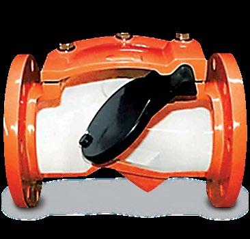
CHECK VALVE
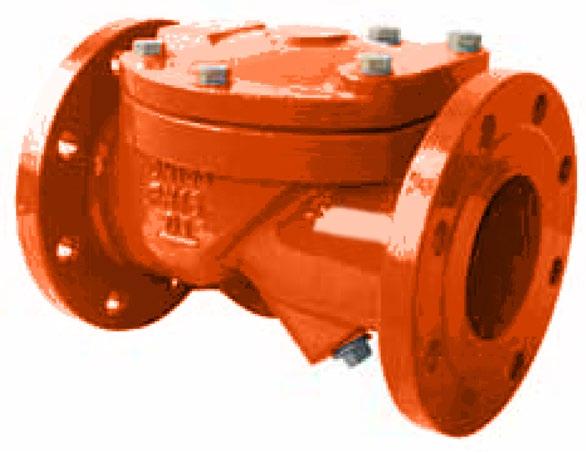
Cast Iron or rubber lined cast iron body, semi flexible disc swing check. Design BS 5158, BSEN 12334.
RANGE OF APPLICATION
Flanging
Connecting dimensions & thickness to ANSI(ASA)/BS/AS/EN/ISO specifications to suit ANSI B16.1, EN 1092-2, PN 6~16, AS 4087 PN 14~16, AS 2129 Table D to E, ISO 7005-1 PN 6~16, AS 4331.1 PN 6~16.
MATERIAL LIST
Body/End Piece Cast Iron IS: 210Gr. FG. 260 with hard/soft rubber lining
Disc (or flap)
Available in neoprene, viton, teflon etc.
Connecting bolts/nuts Steel IS: 1367, Gr. 4.6/4
Valve Surface protection Prime coat: chlorine-free with modified alkyd resin.
Linings Available Food grade, halar, hard rubber, teflon etc.
FEATURES
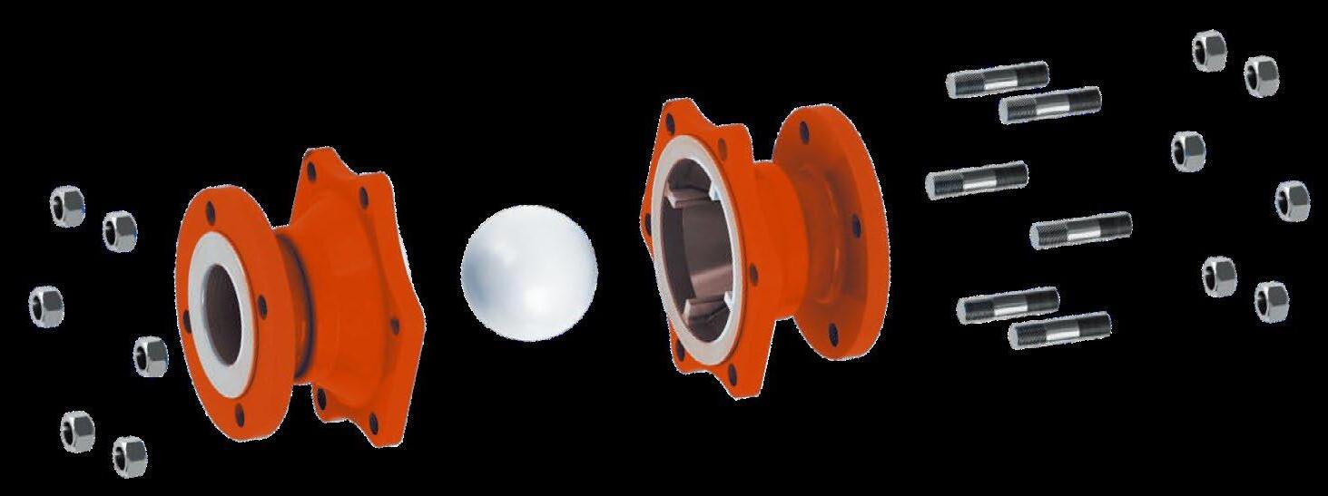
Simple three parts design, with only one moving part. Disc 100% leak tight, 0.035 bar back pressure. Full bore design for minimum flow turbulence. Flap also serves as gasket seal between body and end piece. Valve usable in vertical or horizontal plane. Downtime is kept to a minimum as the flap can easily be replaced in minutes.
DIMENSIONS
Rubber lining specification according to flow medium & working temperature. Cast on flow direction arrow ensures correct installation. When placing order, please specify flow medium, working pressure and working temperature. Not recommended for use under vacuum pressure.
The catalogue is general in it’s nature and design and can vary at any time. This catalogue is to be used as a guide only.
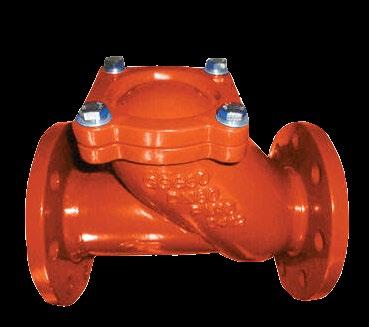
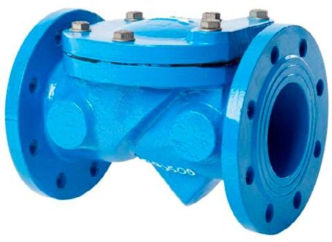
Cast Iron or rubber lined cast iron body, semi flexible disc, swing check. Flow reversal of plus 0.35 bar. Design BS 5158, BSEN 12334.
Flanging
Connecting dimensions & thickness to ANSI(ASA)/BS/AS/EN/ISO specifications to suit ANSI B16.1 125LB, EN 1092-2, PN 6~16, AS 4087 PN 10~16, AS 2129 Table D to E, ISO 7005-1 PN 6~16, AS 4331.1 PN 6~16. EN 1092-2 PN 6~16.
MATERIAL LIST
Body/End Piece Cast Iron IS: 210 Gr. FG. 260 with hard/soft rubber lining
Disc (or flap) Steel reinforced plate rubber lined. Available in neoprene, viton, teflon etc. Grade “B” Butyl is standard.
Connecting bolts/nuts Steel IS: 1367, Gr. 4.6/4
Valve Surface protection Prime coat: chlorine-free with modified alkyd resin.
Linings Available Food grade, halar, hard rubber, teflon etc.
FEATURES
Simple three parts design, with only one moving part. Disc 100% leak tight, 0.035 bar back pressure. Full bore design for minimum flow turbulence. Flap also serves as gasket seal between body and end piece. Valve usable in vertical or horizontal plane. Downtime is kept to a minimum as the flap can easily be replaced in minutes.
DIMENSIONS
Rubber lining specification according to flow medium & working temperature. Cast on flow direction arrow ensures correct installation. When placing order, please specify flow medium, working pressure and working temperature. Not recommended for use under vacuum pressure.
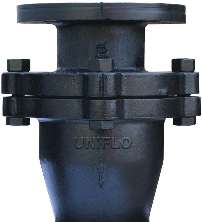
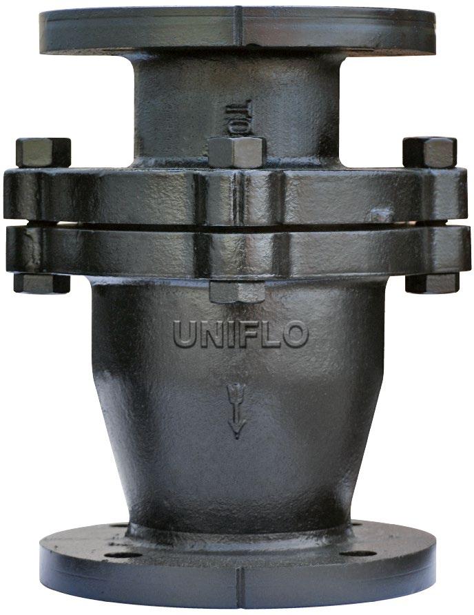
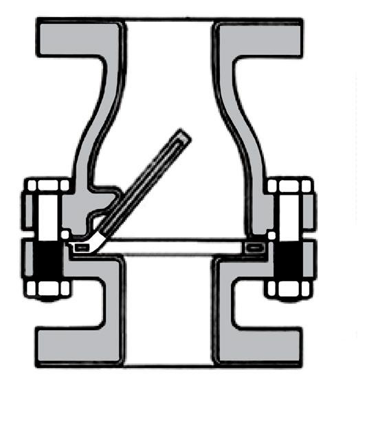
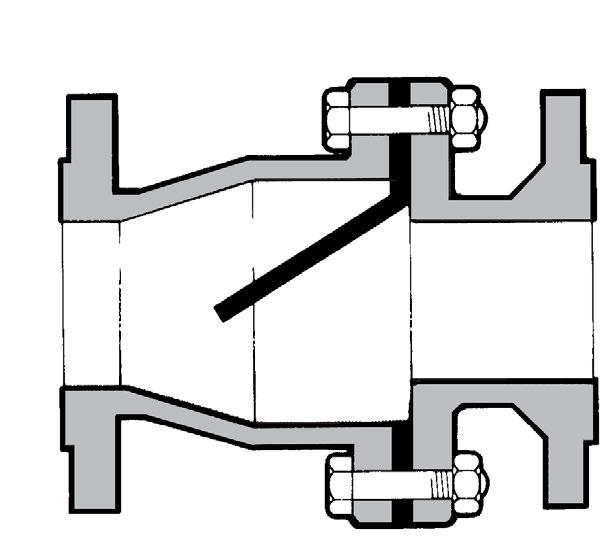
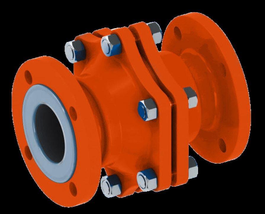
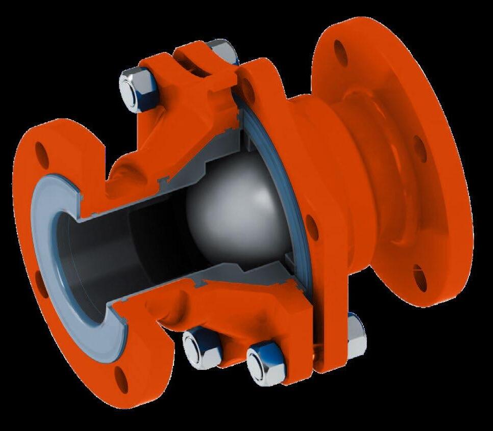
The Uniflo ball check valves are developed for use on fluids compatible with the corrosion resistant characteristics of virgin PFA. These valves can be used in horizontal and vertical installations. The body of the valve is made from a combination of ductile iron and steel. The body parts do not come into contact with the process flow.
SPECIFICATIONS
Size
15mm-200mm (0.5”-8”)
Working pressure 0.1m bar-16 bar
Temperature range -20° C - 200° C according to working conditions, other temperatures on request.
Design and Manufacture API 594
Face to Face
Flange Ends
ASME B16.10, JIS B2002, EN 558-1, BSEN 16767
ASME B16.5 125LB, JIS B2212, AS 2129 Table D & E, AS 4087 PN14, AS 4331.1 PN10, PN16, EN 1092-2 PN10, PN16, ISO 7005-1 PN10, PN16, JIS B2220 5K, 10K, 16K
Visual Inspection Testing MSS SP54
Pressure & Temperature API 598 DIN 12569 JIS B2003 ASME B16.34
Spark testing 14kv
Flange design meets multiple international standards
Lined securely locked into the body by “T” slots and locking grooves, completely encapsulated body permits vacuum services
Min 3mm liner
Epoxy coating paint
Pure PTFE materials ball long life use, super high-precisions machining to make good seal, science on-off performance.
Large open area for flow results in lower pressure drop.
Stainless steel fasteners are standard
LIST
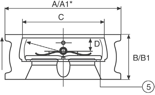
DIMENSIONS
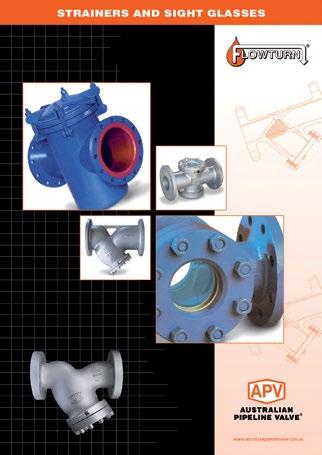
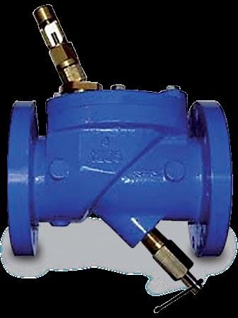
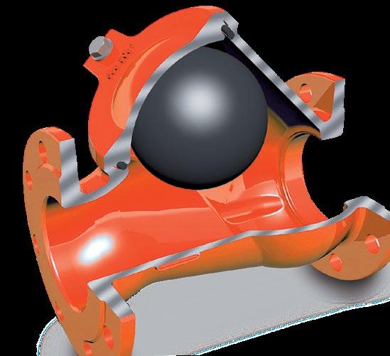
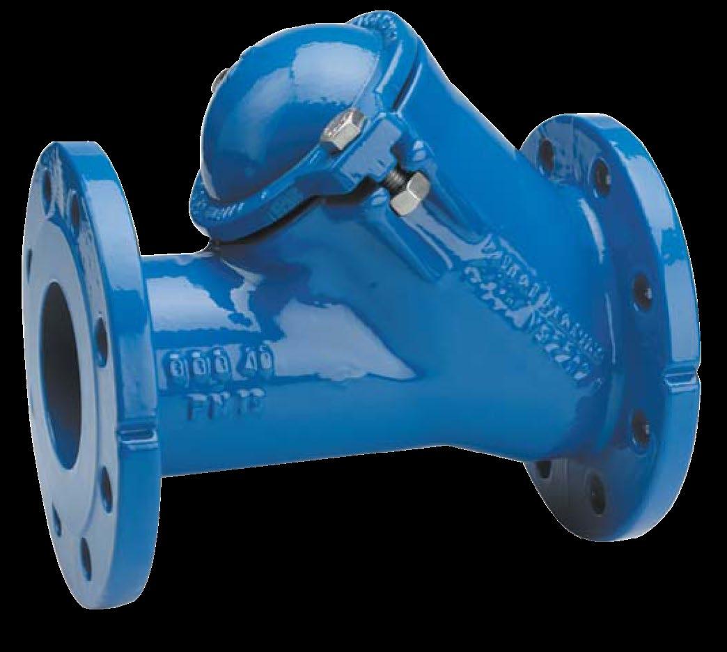
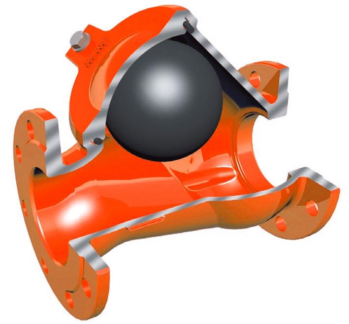
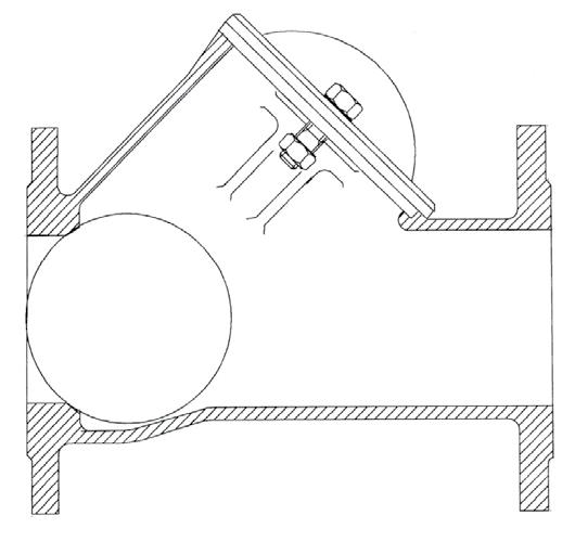
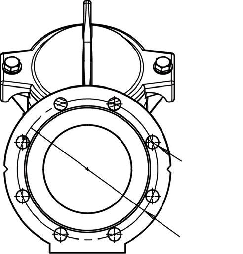
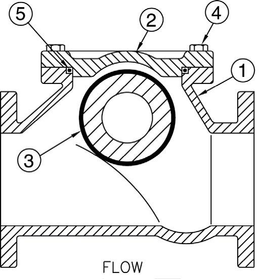
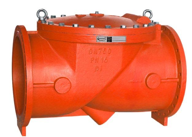
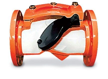
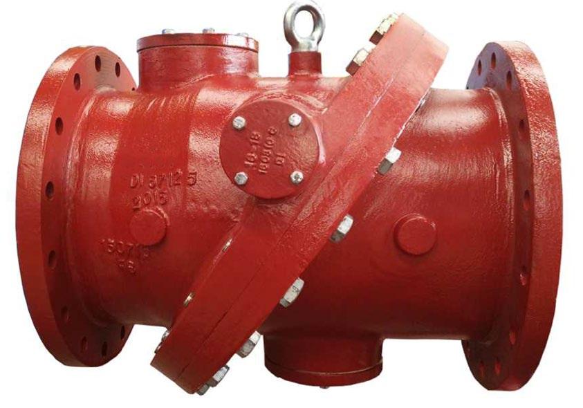
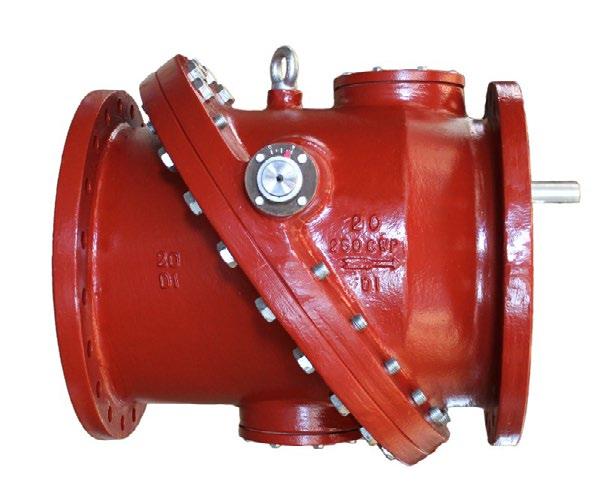
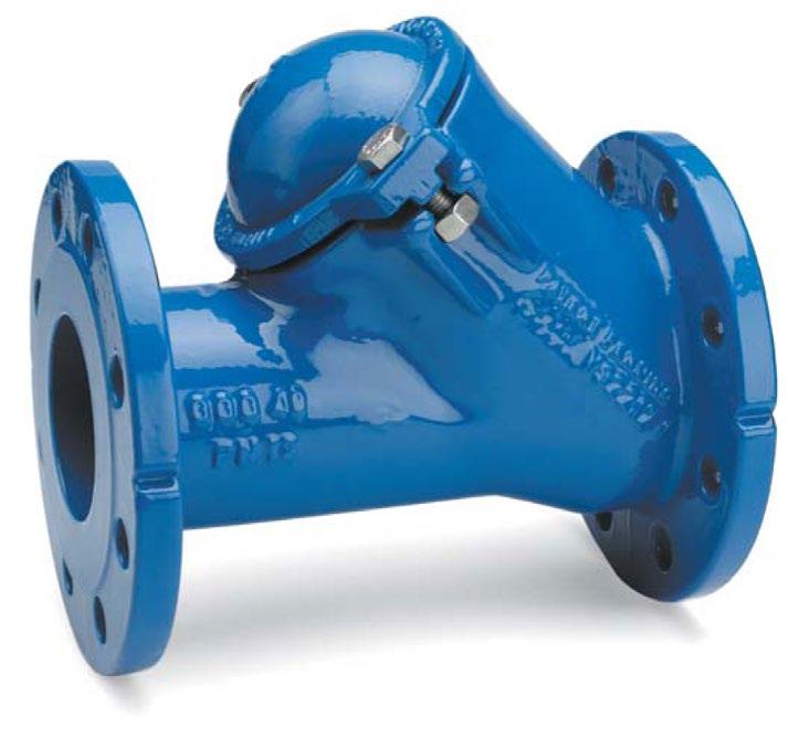
These full port ball checks with uninterrupted flow (equal to bore of pipe) are resistant to clogging and are ideal for wastewater, stormwater treatment, pumping dirty fluids. There is no accumulation of debris/deposits and the valve can be cleaned in-line without removal of entire valve and other neutral liquid applications. They can be used in horizontal & vertical service. BC series check valves have a low head loss and are self-cleaning due to the rotating ball.
Flanging
ANSI B16.1 125lb, 150lb AS 4087 PN14, PN21 AS 2129 Table D, E, F AS 4331.1 PN10, PN16, PN25
EN 1092-2/ISO 7005-1 PN10, PN16, PN25 Face to Face Dimensions
EN 558-1 Series 48 - was DIN 3202-F6 (Dimension L1) AS 4794 (Dimension L), AS 3579, ANSI B16.10
1 1 Body Ductile iron plus Epoxy Coat EN-GJS-400-15 DIN: GGG 40 ASTM: A536 65-45-12 BS: 1563 EN-JS 1030
2 1 Bonnet Ductile iron plus Epoxy Coat EN-GJS-400-15 DIN: GGG 40 ASTM: A536 65-45-12 BS: 1563 EN-JS 1030
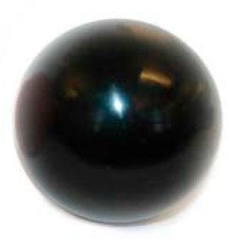
3 1 Ball Nitrile or EPDM coated steel Polyurethane
4 2/4 Nut Stainless steel
5 1 Gasket Nitrile or EPDM
6 1 Degassing plug Stainless steel Optional
Stainless body and PTFE/PFA/FEP coated ball available on request for chemical and high temperature applications.
DIMENSIONS
STANDARDS
Manufacture according to the requirements of the European directive 97/23/CE (Equipment under pressure): category III modulate H. (DN 40-400)
- 26 bar before & after
- 16 bar after lining
Table D - SL404-D-CW
Table E - SL404-E-CW
PN10 - SL404-10-CW
PN14 - SL404-14-CW
PN16 - SL404-16-CW
PN21 - SL404-21-CW
PN25 - SL404-25-CW
125 Class SL404-125-CW
150 Class SL404-150-CW
250 Class SL404-250-CW
Design
BSEN 16767 (BS 5153), MSS-SP71 Type 1, ANSI B16.1
Flanging/Pressure Class
ANSI B16.1125lb, 150lb, 250lb ANSI B16.42 150lb, 250lb AS 2129 table D, E, F, H AS 4087 PN10, PN14, PN16, PN21, PN35 ISO 7005-1, PN10, PN16, PN25 AS 4331.1 PN10, PN16, PN25 EN 1092-2 PN10, PN16, PN25 JIS B2220 5K, 10K, 16K, 20K Face to Face Dimensions
ASME B16.10, EN 558-1, EN 558-2, EN 16767 (BS 5153) (AS 4794 on request)
Test Standard AS 4794, EN 12266-1, MSS-SP71, ISO 5208, API 598
Inside Bush Brass
* Ductile Iron Body for 250 Class and PN16 in larger sizes.
Table D, Table E
PN21,PN25, PN35, 250lb
Table F, Table H
Design
MSS-SP71, BSEN 16767 (BS 5153), BSEN 1074, ANSI B16.1/ANSI B16.42
Features
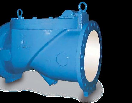
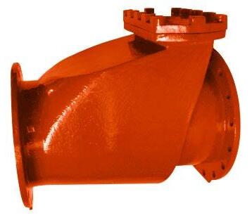
100% full flow area. Fusion Bonded Epoxy. Resilient lined body optional. Simple maintenance-free design, low headloss and non-slam characteristics. The valve’s smooth, unresricted full flow design makes it an excellent choice for slurries and slidge , even in vertical flow up applications.
Flanging/Pressure Class
ANSI B16.1 125lb, 150lb
ANSI B10.42 150lb, 250lb
AS 2129 Table D, E, F AS 4087 PN14, PN16
ISO 7005-1, PN10, PN16
AS 4331.1 PN10, PN16
EN 1092-2 PN10, PN16
JIS B2220 5K, 10K, 16K, 20K
Face to Face Dimensions
ASME B16.10, EN 558-1, EN 16767 (BS 5153) (AS 4794 available)
Test Standard
AS 4794, EN 12266-1, MSS-SP71, ISO 5208, BSEN 1074
Pressure/Temperature Rating
Nitrile 16 bar from -10 to 100ºC
EPDM 16 bar from -10 to 120ºC Viton 16 bar from -10 to 200ºC
MATERIALS

1 Body Cast Iron/Ductile Iron ASTM A126 Class B Over 12” ASTM A53B-Gr65-45-12
2 Cover Cast
3 Gasket Graphite or Butyl Rubber etc. on request
4 Disc Buna/EPDM/Viton/NBR ASTM A-35/0-2000 encapsulated - & nylon reinforced butyl rubber
5 Bolt Steel AISI 1035/SAE Grade 5
6 Inner Coat Epoxy or Lined Epoxy or Chloro Butyl or Bromo Butyl etc
7 Plug Malleable Iron (Optional)
8 Hinge Pin Stainless Steel AISI 31655
* Body material is available in Ductile iron (14 inch and over is standard in ductile iron). Rubber lined or fusion bonded epoxy.
DIMENSIONS 125LB/150LB
*Based on 500 Series, alternative face to face also available.
Refer to drawing for more information
*1Flanging as per AS/BSEN/ISO as required. Refer to drawing for Table D to F and PN10 to PN21.
Design
BSEN 16767 (BS 5153), BSEN 1074
Features
100% full flow area. Resilient lined body optional.
Flanging
ISO 7005-1 PN25
AS 4331.1 PN25
EN 1092-2 PN25
AS 2129 Table F, H
AS 4087 PN21, PN35
Rating 2100kPa CWP 50~80NB 2000kPa CWP 100NB 1600kPa CWP 150NB 1000kPa CWP 200~250NB
Face to Face Dimensions
EN 558-1, EN 16767 (AS 4794 also available)
Test Standard
AS 4794, EN 12266-1, MSS-SP71, ISO 5208, BSEN 1074, API 598
Pressure/Temperature Rating
Nitrile 25 bar from -10 to 120ºC
EPDM 25 bar from -10 to 120ºC
Viton 25 bar from -10 to 200ºC
MATERIALS
Pin Stainless Steel - 31655
* Based on 500 Series, alternative face to face also available. *1Alternative flanging as per AS/EN/ISO as required, refer to drawing.
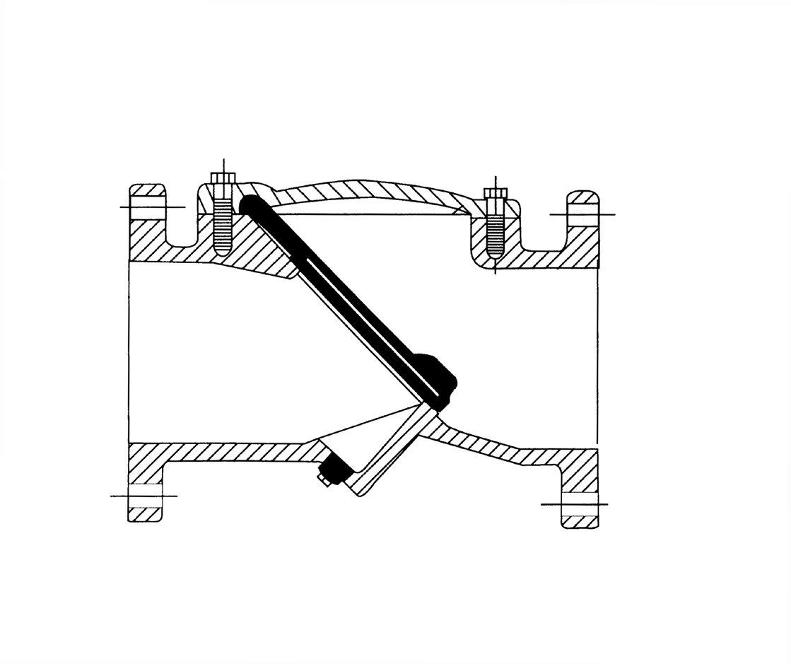
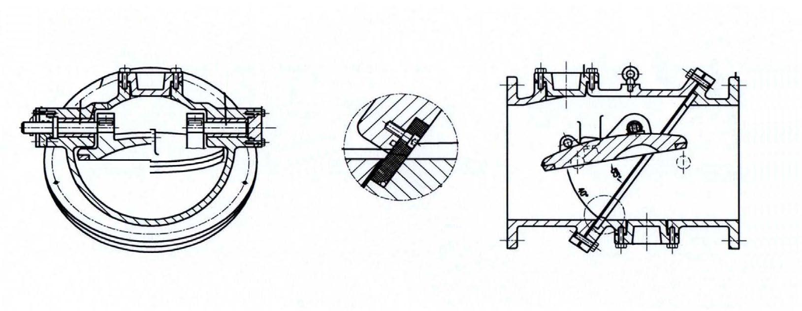
The swing check valves with rubber covered disc belong to the last generation of swing check valves, developed in order to improve the performance and the technical characteristics. These valves are manufactured in ductile iron, with the swing in ductile iron fully covered with NBR rubber. These swing check valves allow the full passage of the flow, with no water losses (compared to classical swing check valves with disc in cast iron). The disc doesn’t need any maintenance & avoids any noise during closure. Epoxy coated inside & outside, these swing check valves are suitable for potable water.
Face to face length EN 558-1 serie 48, DIN 3202 F6. Flanges BSEN 1092-2 and AS 4087/AS 4331.1 PN10 - 16 (PN25 also available to 350NB)
Installation vertical / horizontal (upwards).
DIMENSIONS
MATERIALS
Application
Suitable for all types of water, air & steam 100oC. (For higher temperature, consult us.)
Features
Sizes DN 50 ~ DN 600mm (2”~24”)
Flanging
Flange Drilling to suit ANSI B16.1, ANSI B16.5, BS EN 1092-2, BS 10, AS 2129 D/E and AS 4087 PN 10/14/16.
Test Standard
MSS-SP71 Class 250 & EN 12334 PN16
Optional Accessories
Proximity Switch, Backflow Actuator, Oil Dash-pot, Air Release Plug on the Cover.
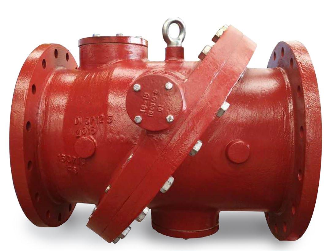
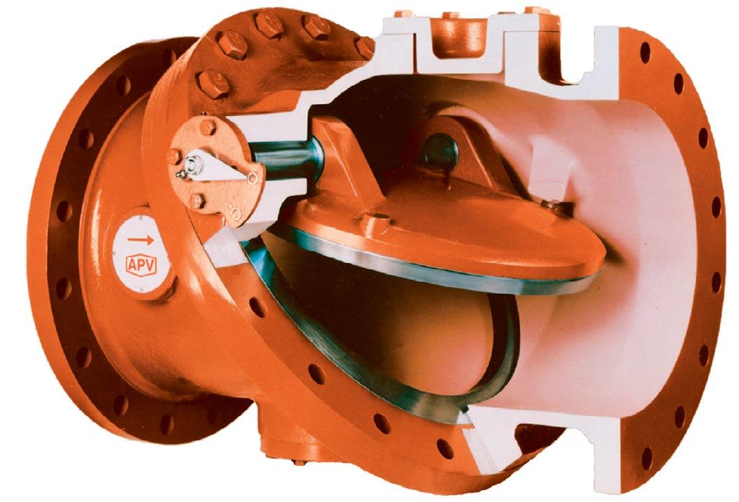
The unique design of the hi-strength fabric reinforced rubber flapper disc creates an elastic spring to close-against the flow, combined with the tilted body seat (closing angle 35o) act to reduce the closing time, minimise the water hammer and flow reversal. Simplicity of design with three components (body, disc & cover) in one valve, and disc, hinge and pin are integral and fully encapsulated with special rubber for maintenance free, longlife, 1,000,000 continuous cycles tested with no sign of wear or distortion to the valve side and seat, body and cover are ductile iron. This valve will operate trouble free for a longer period compared to conventional check valves.
Valves are manufactured and tested in accordance with EN 12334 PN 10/16/25, TIS 383 PN 6/10/16/25. MSS-SP 71 class 125/250, and also meet the requirements of AWWA C508. The tilting disc check valve accomplishes full flow opening by having the disc pivot or tilt in the flow media. The opening stroke range in much less than that of the conventional swing check valve, therefore reduces opening and closing time critical to controlling flow reversal and reduces water hammer. The full flow area with lower headloss ensures Uniflo tilting disc check valve wil operate with the highest efficiency and durability.
FEATURES
Sizes are available from DN 80 mm - DN 1800 mm. (3”-72”)
Flange drilling to suit ANSI B16.1, EN 1092, BS 10, ANSI B165, AS 2129 Table C to E and AS4087 PN 10 to 16.
Epoxy coating to AWWA C210-84 standard.
Optional accessories Signal switch, By-pass, Hydraulic cylinder (top/bottom/side mounted)
1. Pivot Pins and Bushings Maximum strength is achieved by using large diameter high tensile pins.
2. Grease Fittings
Lubrication is not essential however optional grease fittings are used to assure even longer life.
3. Disc Position Indicator Indicates Disc Position.
8. Inspection Ports Ports allow access to the upstream and downstream sides of the seat, and also serve as mounting ports for optional dashpots.
4. Disc and Seat Rings
Superior wear and gall resistance are achieved through the use of materials having a high Brinnell Hardness (BHN) together with a selected difference in hardness between the disc and seat rings.
Leak tight seating is attained at all working pressures by utilizing a 20° seating angle which provides excellent sealing characteristics. This angle is self releasing and therefore prevents any binding of the disc and seat.
7. Stop Lugs
Positive stops are accurately positioned to prevent disc flutter at both high and low flow velocities, while maintaining ultra low head loss characteristics.
5. Disc
A hydrodynamically balanced design ensures minimum resistance to flow, lift and stabilisation, and good flow characteristics.
6. Body
Ultra low head loss is the result of streamlined body contouring and a flow area through the seat which is a minimum of 40% greater than nominal pipe size.
Size Range: 3” - 60” (DN 80 - 1500)
ASME Pressure Classes: 125-300 (PN10 - PN25)
Oil Dashpots Available
Fusion Bonded Epoxy (FBE) Available Available in Iron or Carbon Steel Construction
Uniflo Tilted Disc Check Valve provides energy efficient operation, while easily handling the most severe and demanding applications with features such as: non-slam closure, wear resistance, leak tight seating and versatility of operation.
Other Size or Pressure, Refer to Drawing.
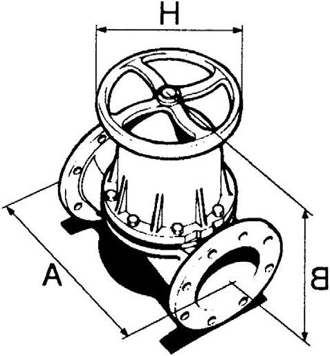
DIAPHRAGM VALVE - WEIR & STRAIGHT THROUGH
APA Weir Type Valve offers smooth flow & simple operation in any position. Parts interchange with the existing market leader of diaphragm valves and dimensions are the same. Its design provides extra-long diaphragm life for throttling and positive shut-off services. Hygienic style also available.
Size Range 8mm to 350mm.
Design
EN 13397 (BS 5156)
Temperature Range -45ºC to 171ºC.
Body Linings
Hard Rubber, Soft Rubber, Neoprene, Glass, Butyl, Ceramic, PFA, PP, ETFE, Polypropylene, Halar & PVDF
Diaphragms
Pressure Range to 1580 kPa.
Body Materials
Cast Iron, Ductile Iron, Bronze, Aluminium and Stainless Steel
Flangings
AS 2129 Table D/E/F ANSI 125 AS 4087 PN14/PN16 AS 4331.1 PN10/PN16.
Butyl, EPDM, Polyethylene, Polychloroprene.
Design Advantages
The body of which gives a smooth pocketless flow and features low pressure drop. Suitable for high line pressure duties and is available in a range of trims & materials for gases and liquids.

Bonnet Assembly
Contains a compressor which supports the diaphragm at all stages of travel
Diaphragm
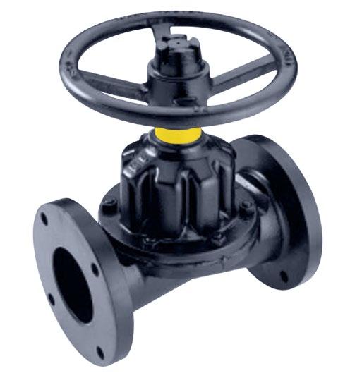
Specially shaped to achieve leak tight seat against wall.
The catalogue is general in it’s nature and design and can vary at any time. This catalogue is to be used as a guide only.
APKB Straight Thru Valves efficiently handle abrasive and corrosive slurries, thick coagulating fluids, and a wide variety of suspended solid materials. Parts interchange with the existing market leader of diaphragm valves and dimensions are the same.
Size Range 15mm to 350mm.
Design
EN 13397 (BS 5156)
Temperature Range -40ºC to 121ºC.
Body Linings
Cast Iron, Hard Rubber, Soft Rubber, Neoprene, Glass Lined, Butyl, Ceramic, PFA, PP, ETFE, PVDF.
Diaphragms
Pressure Range
Vacuum to 690 kPa.
Body Materials
Cast Iron, Ductile Iron, Bronze, Aluminium and Stainless Steel
Flangings AS 2129 Table D/E/F ANSI 125 AS 4087 PN14/PN16 AS 4331.1 PN10/PN16. DIMENSIONS,
Butyl, EPDM, Polyethylene, Polychloroprene.
Design Advantages
The body design offers minimum friction, no turbulence & is suitable for sludge and slurry pressure gases.

Bonnet Assembly
The compressor & spindle design gives a long travel sufficient to contact the valve body seat & to lift the diaphragm up into the bonnet to provide total clearance of the pipeline.
Diaphragm
Specially shaped to achieve leaktight seat against valve wall.
Body
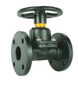
Allows greater flow and is suitable for rodding through.
125LB, PN10, PN14 & PN16
Rating API 594 - Class 125/150 or AS/EN/ISO/BS PN10/ PN14/PN16
Design API 594, BSEN 16767
Max temp -18°C* to 100°C Buna - N, -18°C* to 110°C EPDM, -18°C* to 121°C metal seat (As Body).
Flanging To suit ASA 125, 150, EN1092-2 PN10/PN16, AS 2129 Table D, E, AS 4087 PN14/ PN16/PN21, ISO 7005-1 PN10/PN16, AS 4331.1 PN10/PN16, EN 1092-2 PN10/PN16, JISB 2220
5K~20K
Face to Face EN 558 (was DIN 3203-K3), BSEN 16767 or EN 16782 (3202-K3) or ASME B16
Test API 598/ISO 5208/MSS SP67-1
Metal seated leakage 3CC/min/inch of valve size per API 598.
Soft seated leak tight shut off.
* Iron body limitation -18°C
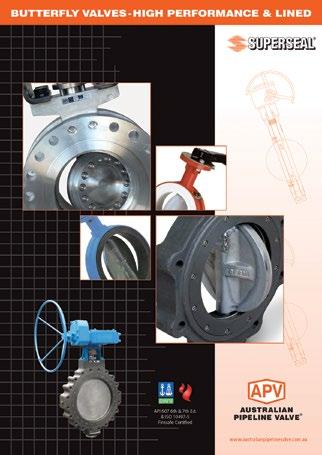
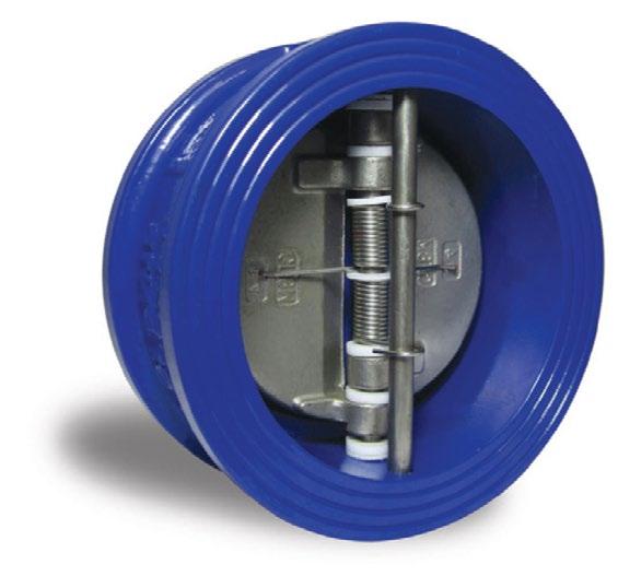
DESIGN FEATURES
Encapsulated and bonded body seat (soft seat)
Upper and lower PTFE thrust bearings
Dual springs for quicker activation long life and even distribution of force over both plates
Fusion bonded epoxy coated body (internal & external)
Long leaf springs (prevent rubbing of disc and seat)
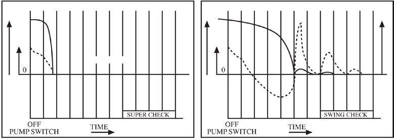
Alleviation from Water Hammer
Reaction of torsion spring makes plates rapidly close prior to the start of reverse flow of fluid due to the stop of power, thus prevents damage from water, hammering caused by pumps and other reciprocating devices.
Lower Head Loss
Designed with optimum venturi to reduce head loss when compared with similar Dual Plate Type Check Valves.
Installation Directions
In addition to the compact size, SUPER-CHECK valves can be installed either horizontally or vertically.
Long Leg Torsion Spring
Action which allows the plates to open and close without seats scrubbing.
Super-Check provide a complete range of sizes from ND40 through ND 1800, designed and rated in accordance with ANSI 125 LB, PN10, PN14, PN16, PN21
OF
Name Materials 1 Body Iron 126 Class B, Ductile Iron+FBE 2 Plate Bronze, 304SS, 410SS, 316SS, Duplex, iron 3 Springs (Long Leg) 316SS 4 Pin 304SS or 316SS 5 Body Seat NBR (BUNA), EPDM, Viton, Metal
Bearing PTFE
Retainer S25C or S/S
Eye Bolt SS41
O-Ring Viton, NBR, EPDM
Ensure the valve is at least eight pipe diameters from reciprocating or pulsating devices.
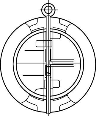
SLIM PLATE DESIGN
Standard in all sizes. Ensures lower cracking pressures & large flow rates.
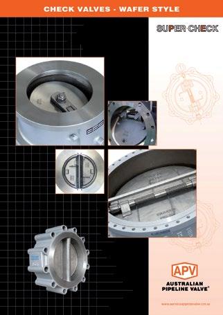
SUPER-CHECK is a non-slam check valve because it operates on flow cessation, not flow reversal. The normal position of the plates is closed, held against the seat by the unique spring design. As flow begins, the heels of the two plates are lifted off the seat face on the central rib.
This cracking pressure is less than 14 kPa (2 psi) across most of the range (larger sizes can be more). As flow increases, the plates then pivot against the spring pressure. Since the heels have already lifted off the seat there is no scrub or wear, either on the seat, body or plate seating surfaces. A pressure of only 28 kPa (4 psi) is required to keep the plates fully open (up to 400 NB).
When flow stops and the pressure ceases, the spring closes the plates. Flow reversal is then stopped by the closed Supercheck valve and in fact any back pressure only serves to make the valve seal more tightly.
“Australian Pipeline Valve produces isolation, control and flow reversal protection products for severe and critical service media in utility, steam, pipelines, oil & gas and process industries. APV valves and pipeline products form the most competitive portfolio in the market.”