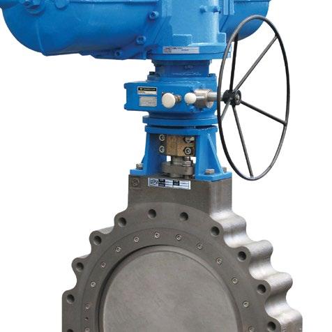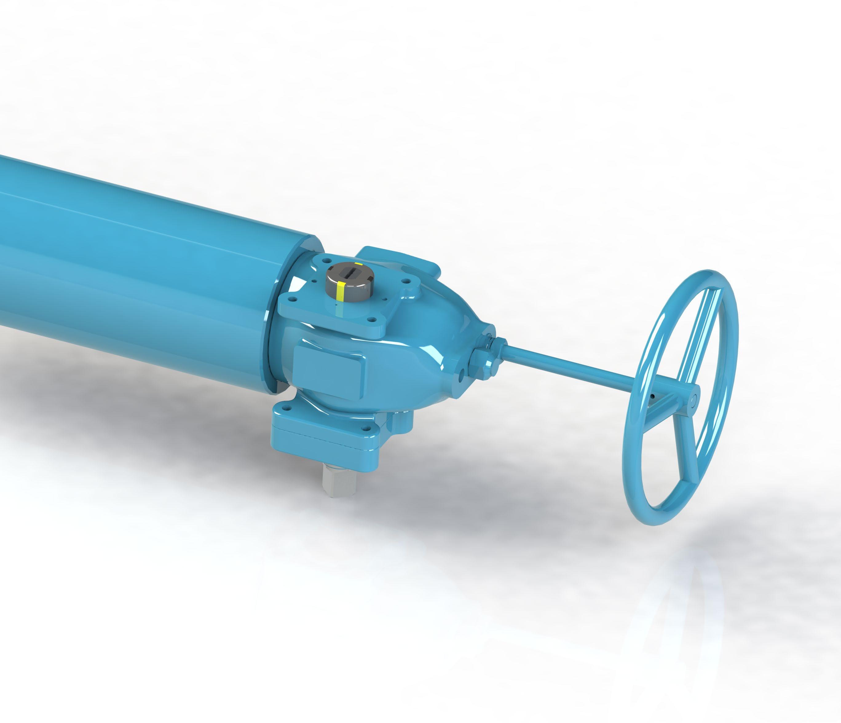
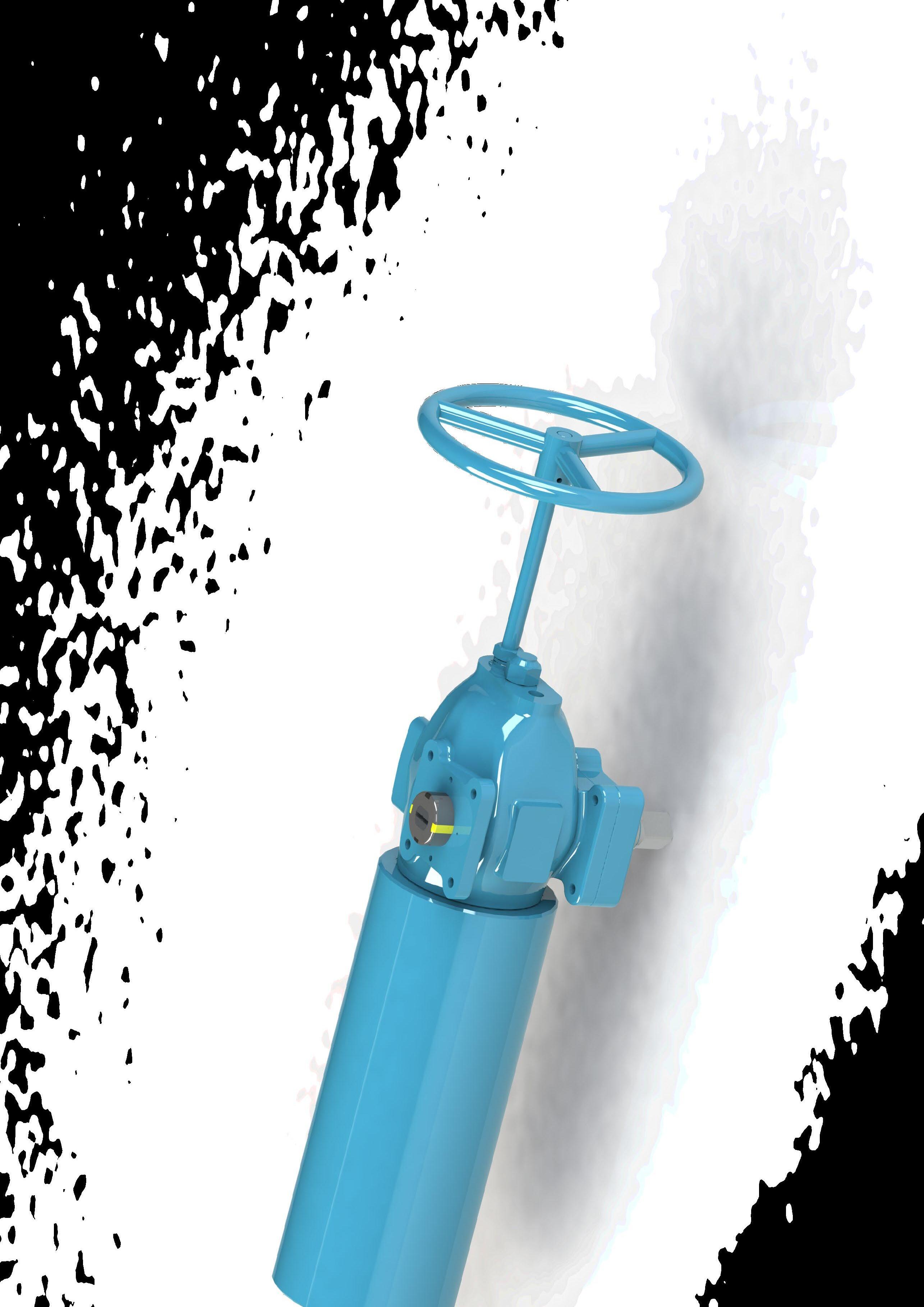


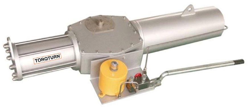

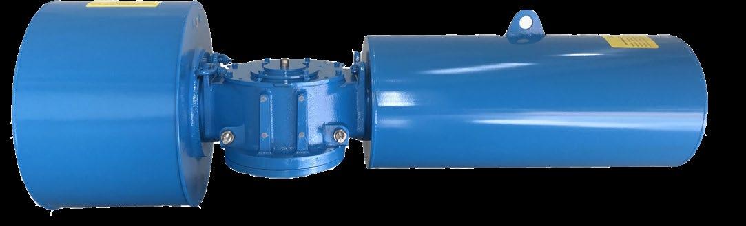
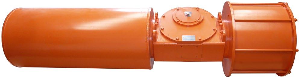
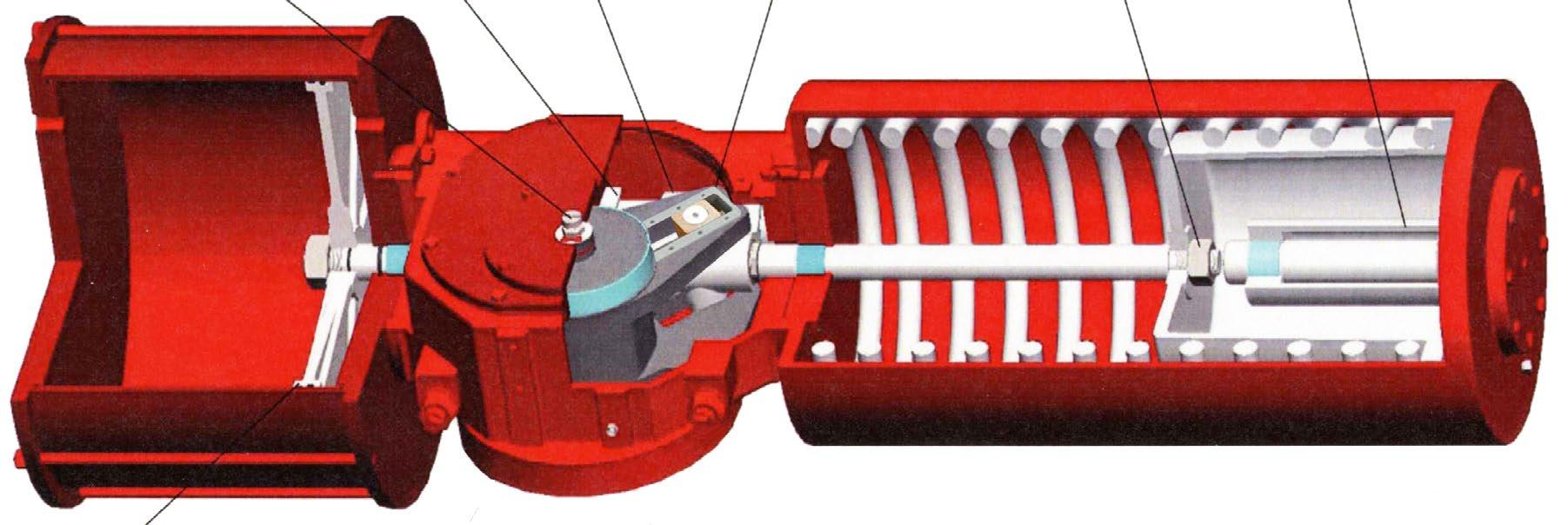
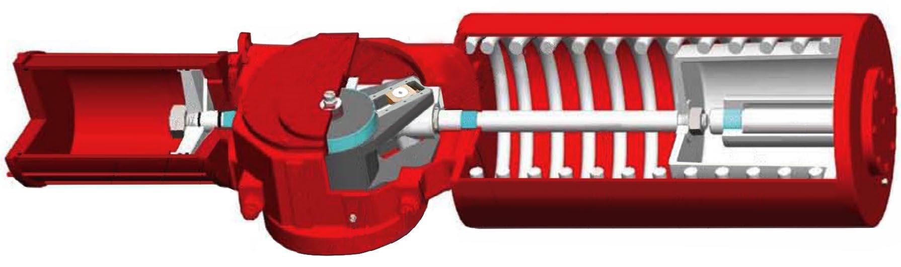
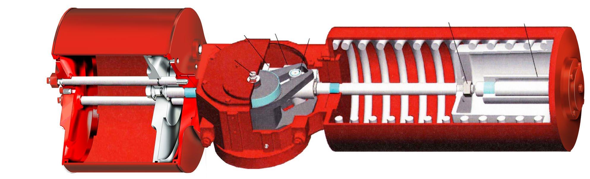
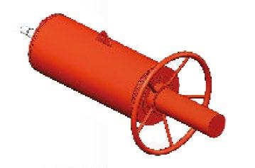
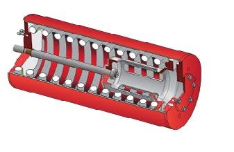
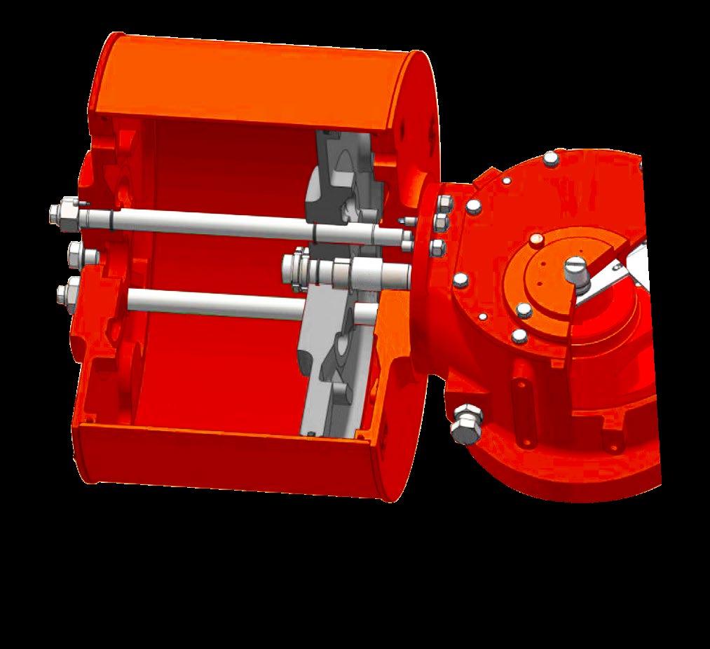
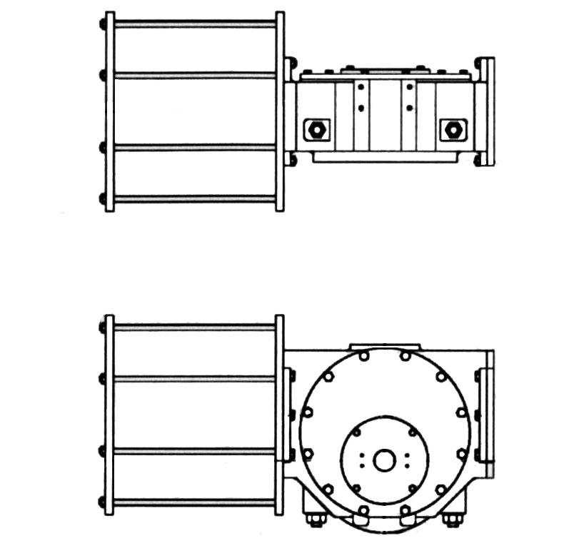
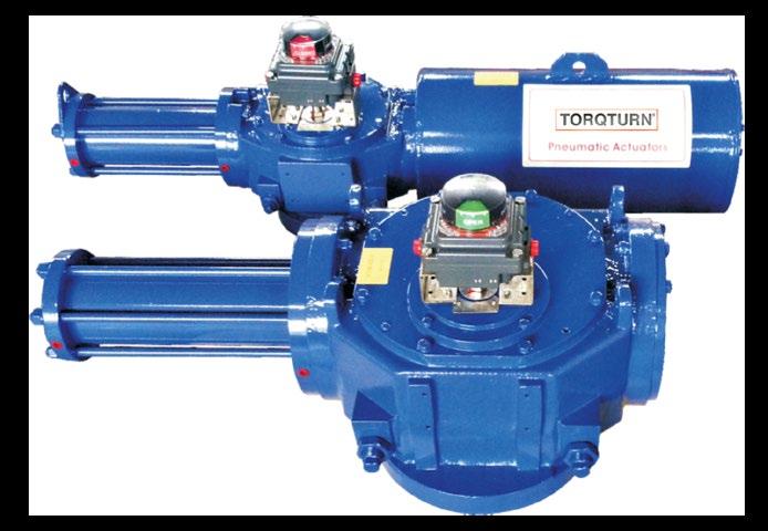
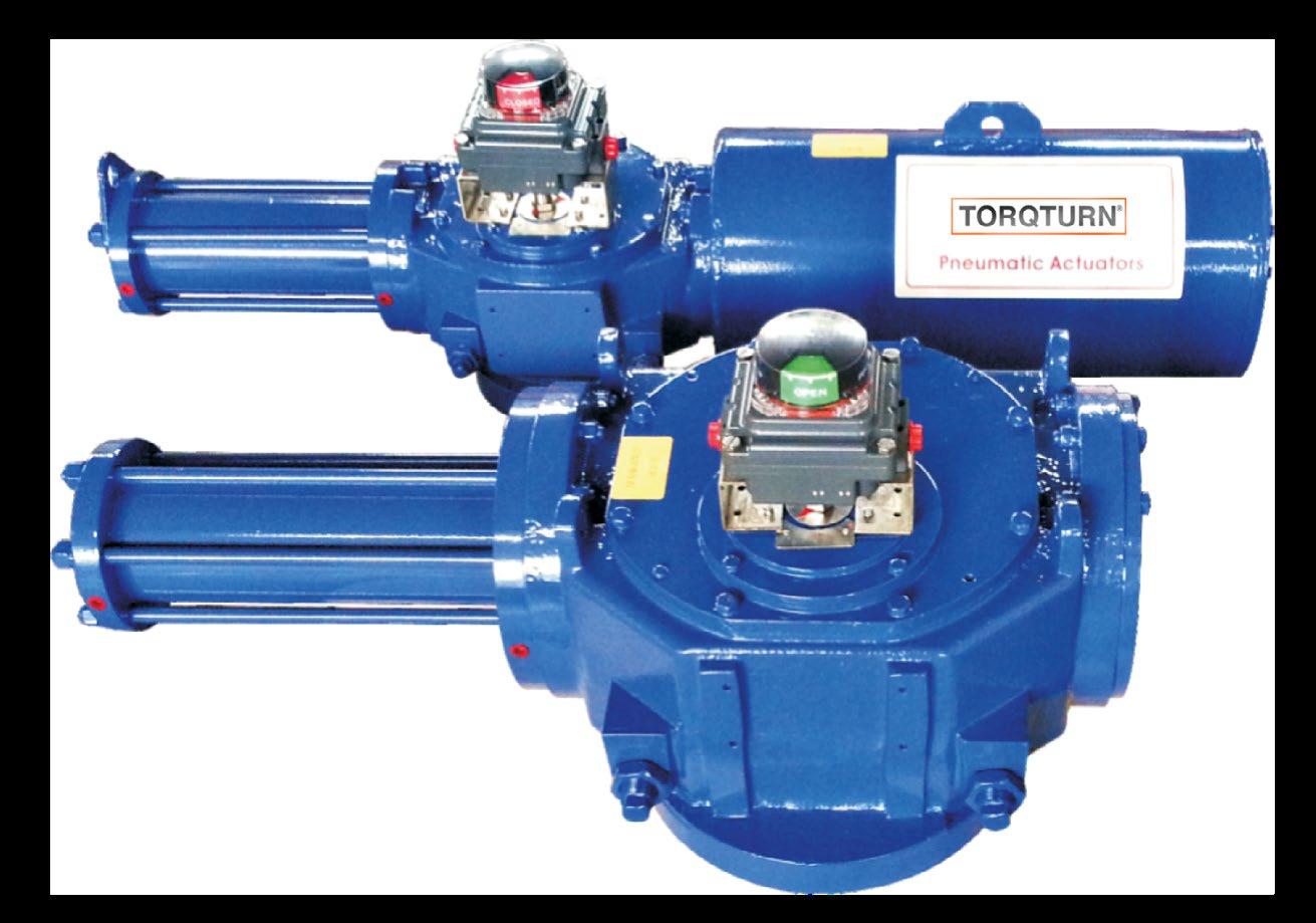
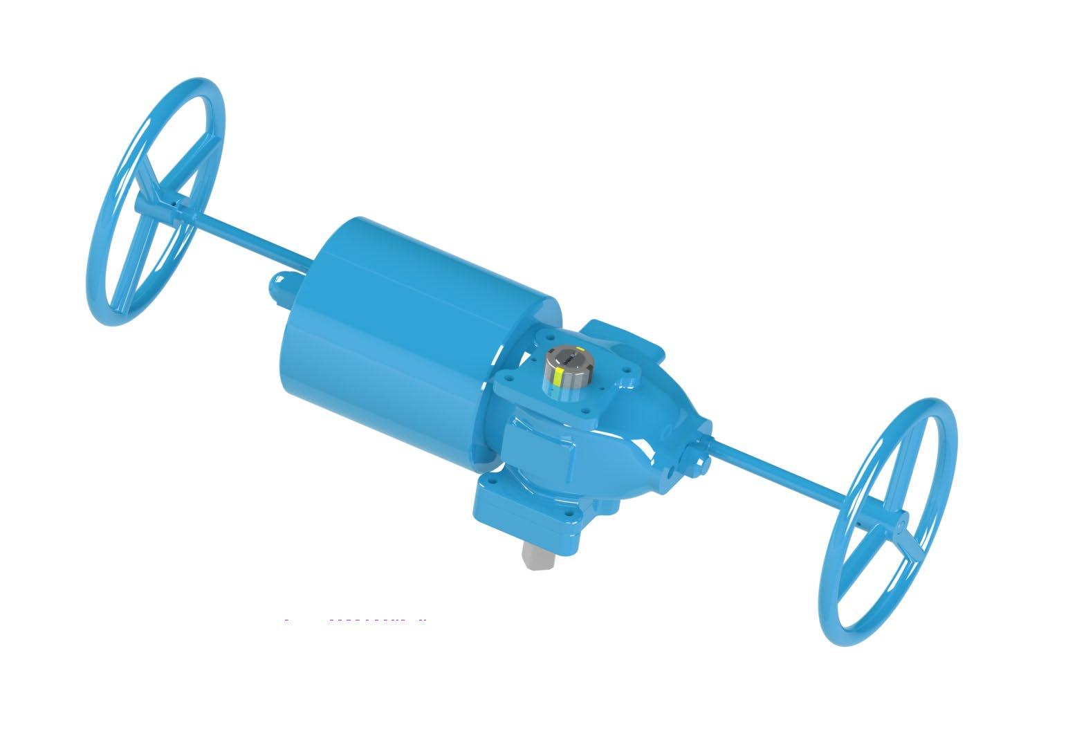
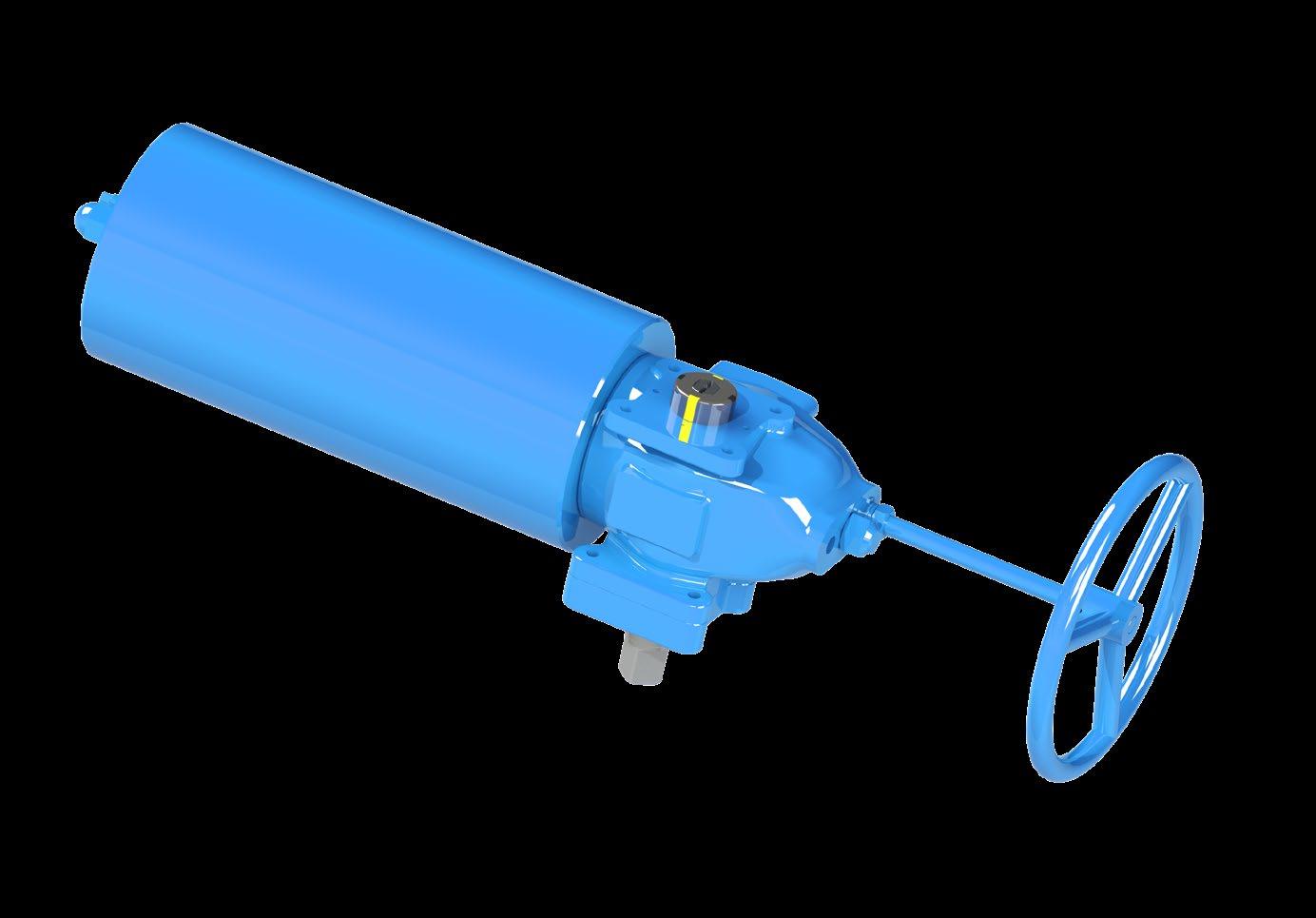
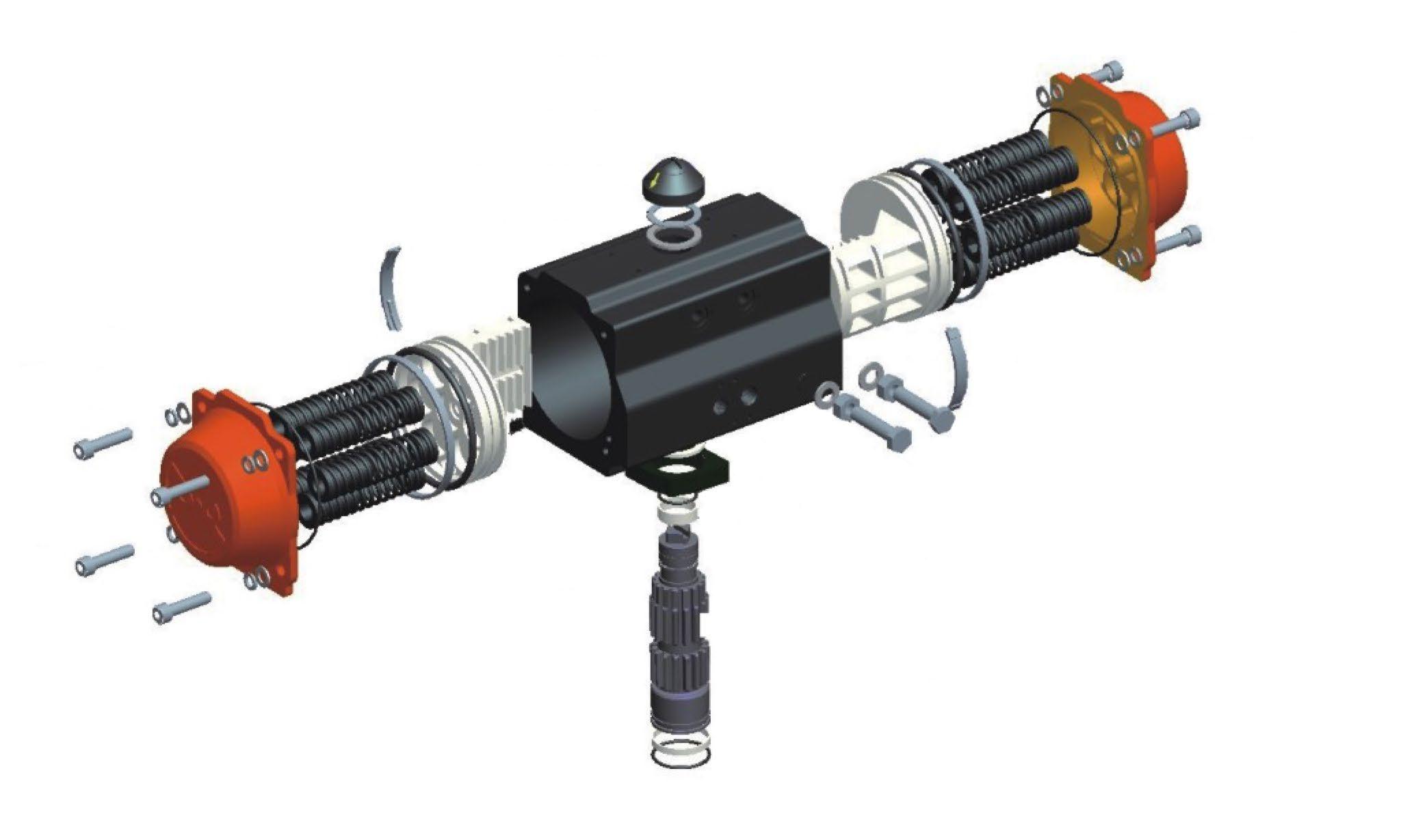
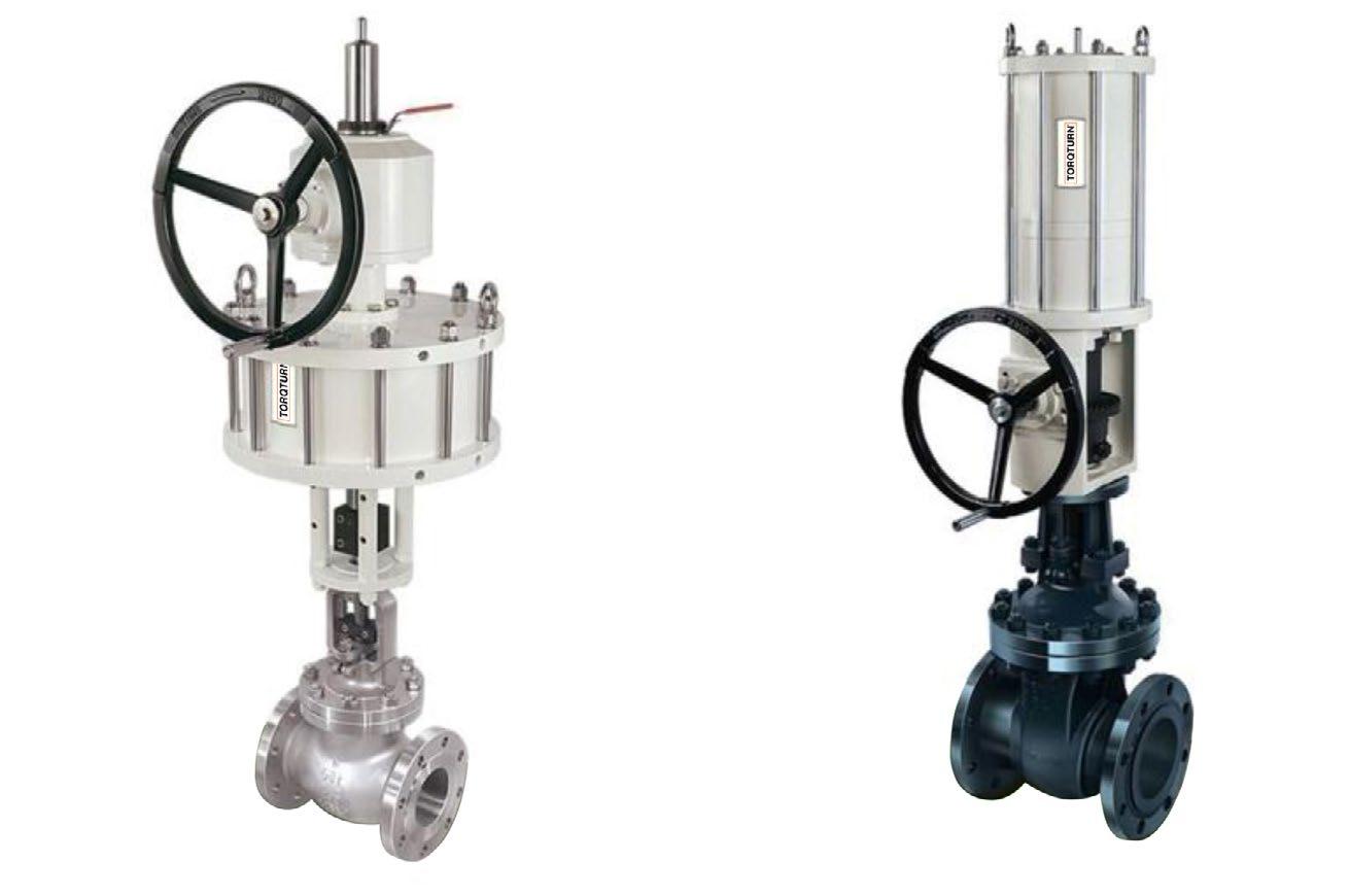
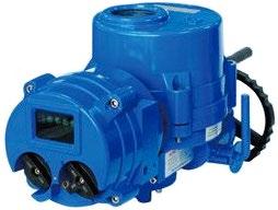
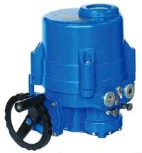
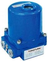
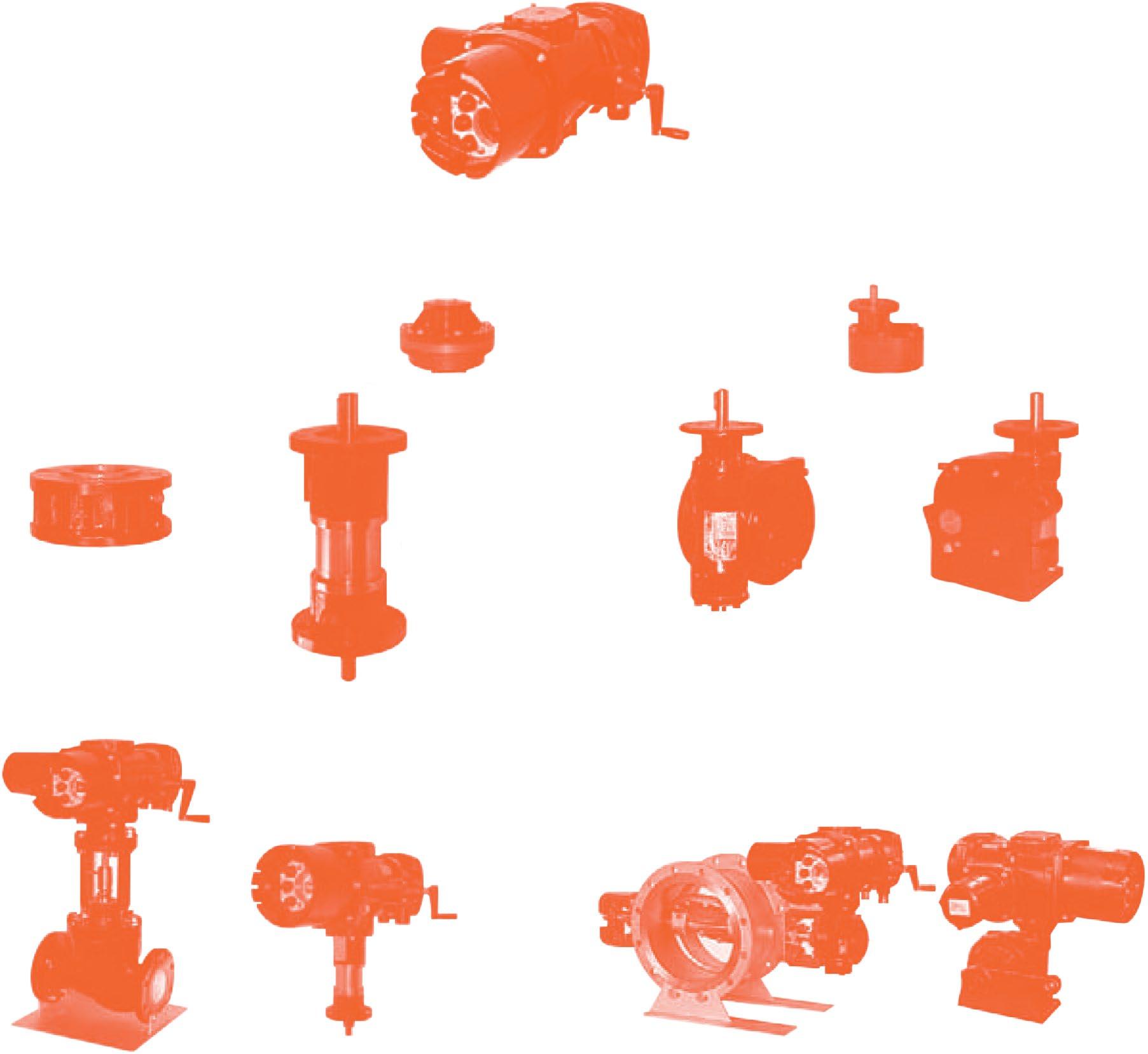
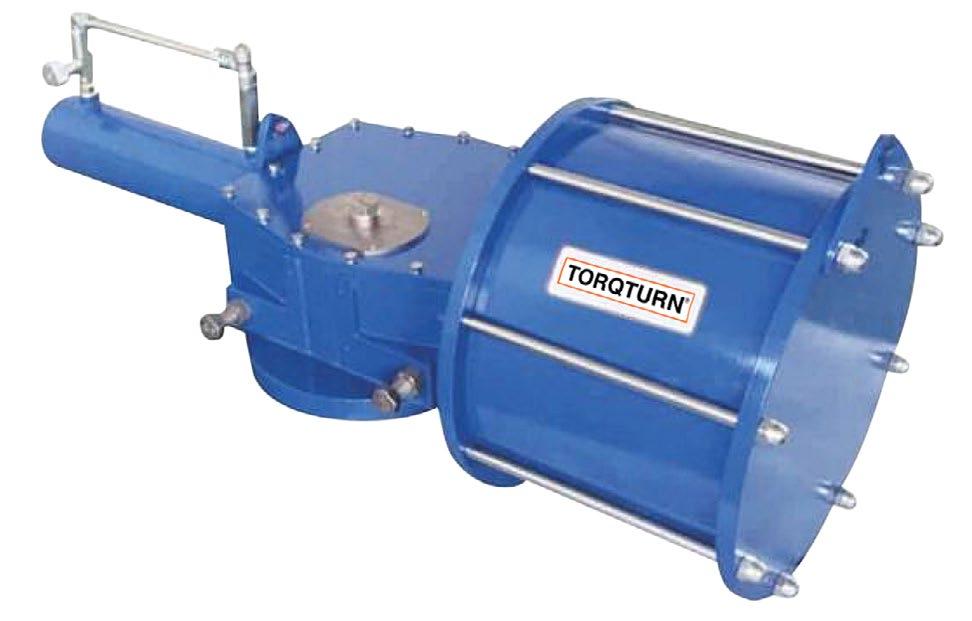
G Range Scotch Heavy Duty Yoke actuators are available in hydraulic and pneumatic and provide a large torque range compact body design. G Range actuators are an improvement on the basic competitors scotch yoke concept and feature an improved reaction bar in addition to adding replaceable bearings, a highly efficient wear and corrosion resistant coating system and a tension rod compressed spring. This enhanced design greatly improves efficiency, reduces wear and extends the actuator’s life. The combining of these technologies, enhancements, and superior quality control techniques ensures a high quality assembly which forms the heart of our extended service actuators - the G Range.
APPLICATIONS
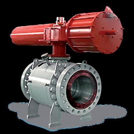
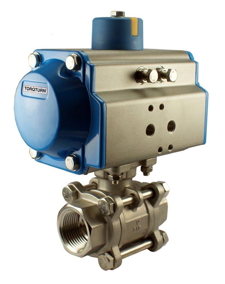
Automation of any quarter-turn mechanism such as Ball, Plug and Butterfly Valves.
FEATURES
Service Rated - G Range models are qualified by accelerated wear testing. The actual service life may be predicted based upon specific application parameters and environmental conditions. Proper actuator selection, enhanced by proprietary data analysis methods, allows optimum performance and operating economy
Replaceable Bearings - Low friction, permanently lubricated, high performance bearings protect sliding and rotating components, significantly extending actuator life.
Four Year Warranty - G Range actuators are backed by the industry’s strongest materials and workmanship warranty.
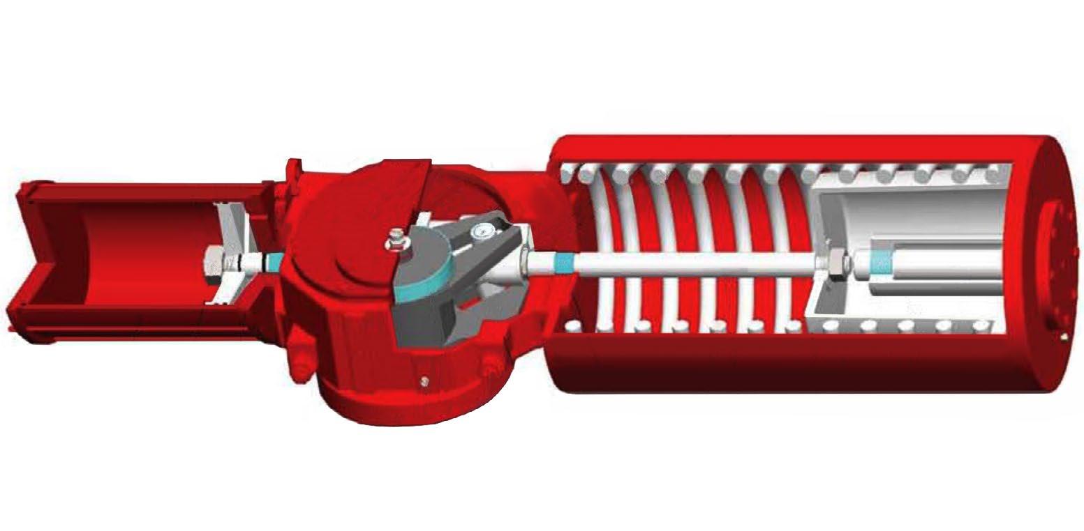
Corrosion Resistance - G Range actuators incorporate protective internal and external coatings, assuring the actuator’s reliable operation in the harshest of environments. The air/hydraulic cylinder is PTFE/XYLAN lined for further corrosion resistance which also reduces friction providing ease/smoothness of operation. The actuator exhibits excellent corrosion resistance, confirmed by Salt Spray Testing. Construction features prevent water ingress, allowing G Range actuators to meet IP 66 and IP 67M specifications. The G Range tension rod is a high strength alloy steel treated to provide a highly corrosion and wear resistant finish. The superior surface finishes, and self-lubricating bearings maximise the transfer of input energy directly to the valve stem. The tension loaded spring minimises radial loads on the piston rod, further enhancing efficiency.
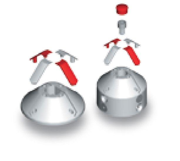
Safety - The G Range facilitates safe installation and removal of the spring module. It allows for the removal of the spring module in a manner that eliminates accidental release of the spring force.
Interchangeability - The ease of interchanging the power and spring modules allows quick reversal of the “fail-safe” mode, while providing for the addition of over-rides, accessories and other modules.
Design - The G Range modular design features field serviceable modules. The available modules include the drive, power, spring and over-ride. These modules are removable, serviceable and interchangeable without removing the actuator from the valve. This procedure does not require special tools or disassembly of any module. This unique feature reduces required plant shutdown time for service. Modules may be replaced as an assembly or serviced at your maintenance facility.
Modular Inventory - All modules may be purchased separately or in any combination. This features allows reduced parts and spares inventory at the distribution facility, while substantially increasing the availability of different model configurations.
Namur - The shaft driven accessory interface conforms to the NAMUR standard and is identical on all G Range actuators, allowing for standardisation of accessory mounting hardware and installation practices. Compact - The G Range design optimises the centre of gravity location, is significantly lighter, and requires less space than other actuators of equal or lesser torque output.
G
PNEUMATIC & HYDRAULIC
ADVANTAGES
Corrosion Protected
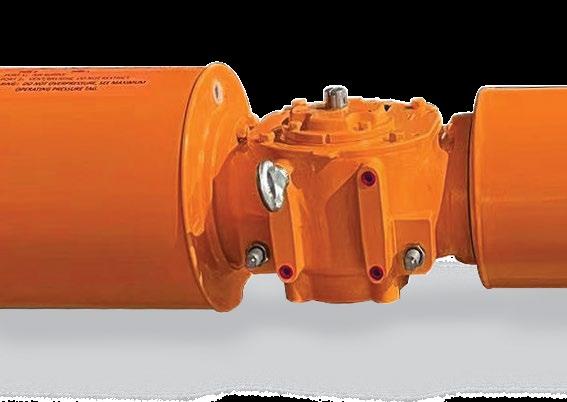
O-Rings are fitted on body caps and all joints. This ensures an effective seal to prevent ingress of water. With one way vent checks, total O-Ring sealing, the orange design prevents water ingress and seals out the environment.
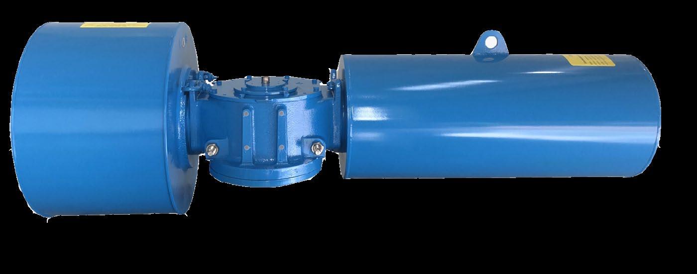
Also the Air/Hydraulic cylinder is XYLAN/PTFE lined. Tie-bars on the GP/GH power module are corrosion resistant, and internal and external surfaces are coated to protect in harsh environments. The AGP/AGH Series has no external side bars.
ISO Valve Mounting
The G Range Actuators interface meets ISO 5011 standard, and meets the dimensional requirements of ISO defined for each torque range.
Standardised Interface
The shaft driven accessory interface conforms to NAMUR and are identical on all G Range models, allowing standardisation of accessory mounting hardware and installation practices.
Wear Resistant
The guide rod and piston rod have an advanced surface treatment, which combined with self-lubricating bearings, provides superior wear resistance and extends the life of all sliding components.
High Efficiency
The piston rod and guide block connection have superior surface finishes and self-lubricating bearings to maximise input energy transfer directly to the valve stem. Efficiency is further
GENERAL APPLICATION
Double acting: 830~250,000 Nm
Spring return end torques: 307~71764 Nm
YOKE DESIGN
Symmetric or Canted (Inclined) Yokes
enhanced by the tension - loaded spring, minimising radial loads on the piston rod.
Bidirectional Travel Stops
Integral bidirectional travel stops, adjustable from 80°to 100° of total valve travel prevents excessive valve seat wear.
Long Service Life
The G Range actuators incorporate four stages of internal and external coatings to resist severe weather, chemical and petroleum environments. The inner surface of the air cylinder is coated with PTFE/XYLAN providing enhanced corrosion resistance and self-lubrication.
Modular Design
G Range actuators design provides field serviceable drive, power, spring and over-ride modules. The modules are removable, serviceable and inter-changeable without the need to remove the actuator from the valve. Modules are available for separate purchase to reduce spare parts inventory.
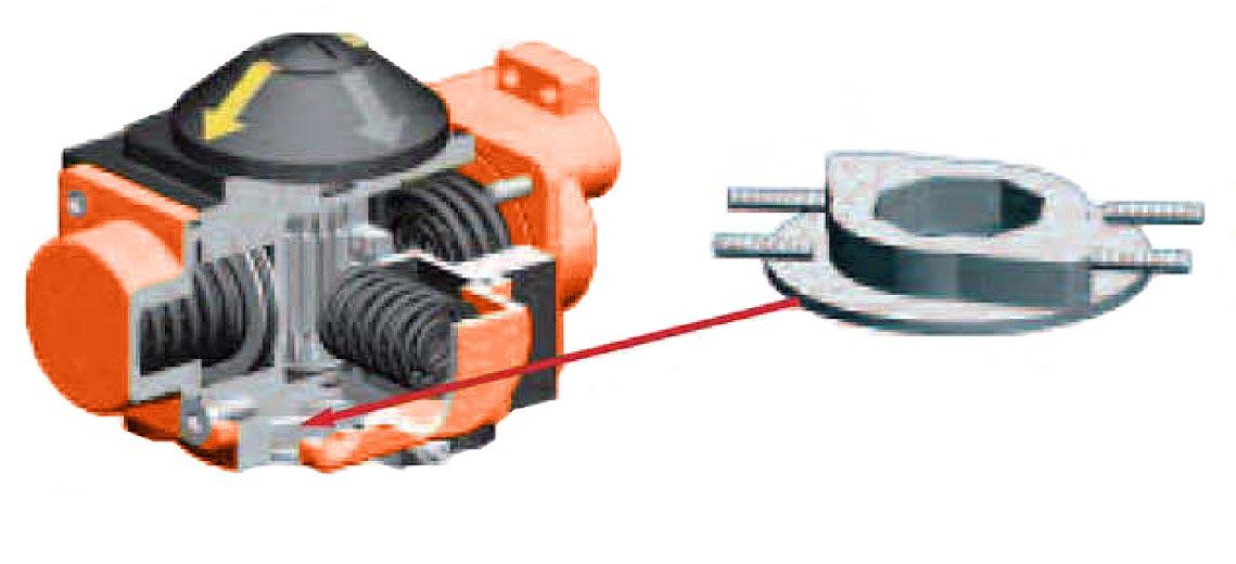
Spring Module
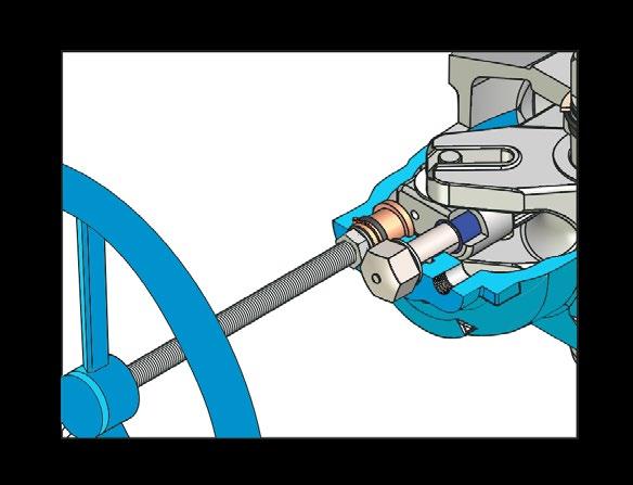
To ensure the safety of personnel during installation and maintenance, the spring module has been designed so that it can only be removed from the power module with the spring in the fully extended position.
This prevents accidental release of the spring force, protecting personnel from injury and the actuator from accidental damage.
Standard: -20°C~80°C Pneumatic: 3~7 Bar
Low Temperature: -40°C~80°C
High Temperature: -20°C~120°C
Torqturn G-Range actuators are available with either symmetric or canted yokes. The traditional symmetric yokes provide efficient operation at both the ‘end to close’ and ‘break to open’ positions. Canted yokes provide higher ‘break to open’ torques and are used where lower ‘run’ and ‘end’ torques are acceptable. Torqturn actuators utilise the optimal solution depending on actuator size.
Hydraulic: 70~200 Bar
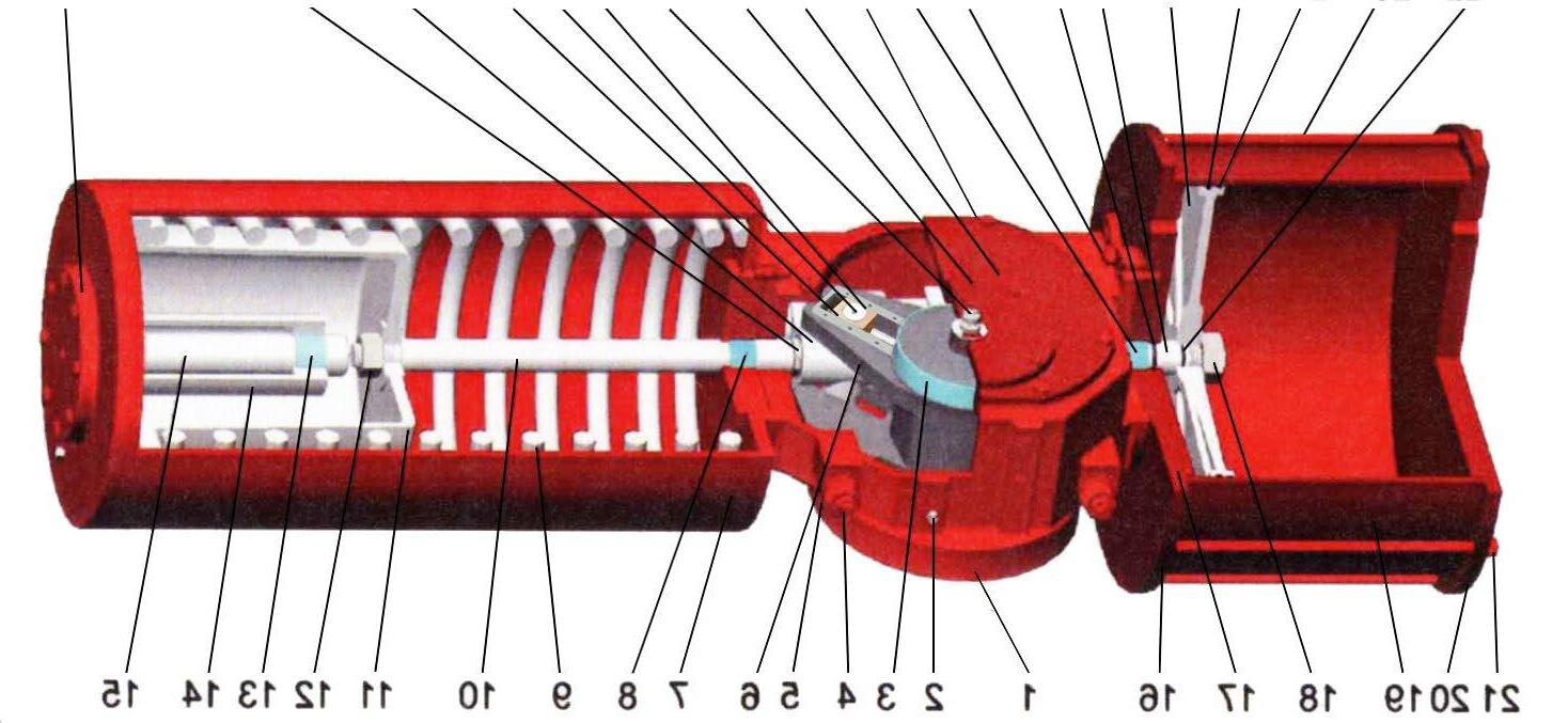
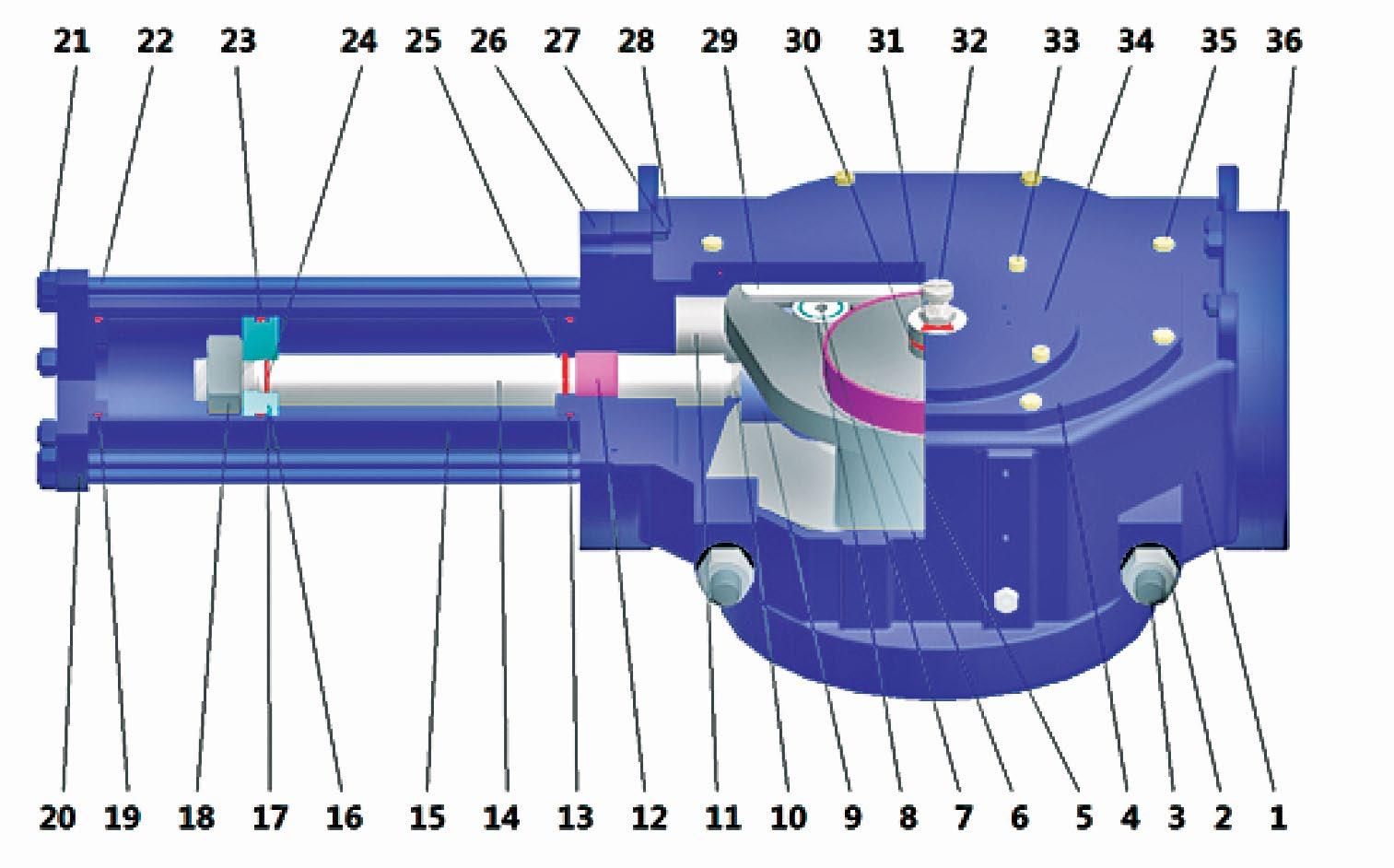
1. Safe Spring Lock
Positively locks the spring module in place under load. Prevents spring module detachment from the drive module.
2. Reduced Wear
The design of connection between the piston rod and the guide block compensates for side load deflection and there by reduces wear on the rod, bearings and seals.
3. Standardised Mounting
The NAMUR mounting configuration allows standardisation of mounting hardware for a wide range of shaft driven accessories.
4. Replaceable Bearings
Replaceable bearings protect sliding and rotating components, with suitability for either dry or lubricated working conditions.
5. Coated Guide Bar
PTFE coated chrome moly thrust bar prevents yoke pin axial movement, transferring axial loads directly to the drive module case.
6. Optional Over-ride
Internal hydraulic over-ride cylinder module for spring-return models doesn’t increase actuator length.
7. Ease of Lifting
G25 and larger models are equipped with four lifting eyes for safe actuator handling during shipping installation and removal.
8. Integral Housing Vent
The main actuator housing incorporates an integral check valve in order to release overpressure.
9. 80°~100° Travel Adjustment
Bi-directional travel stops are integral to the actuator. The stops allow 80° ~ 100° total travel adjustment and are designed to prevent ingress of foreign matter and water.
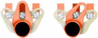
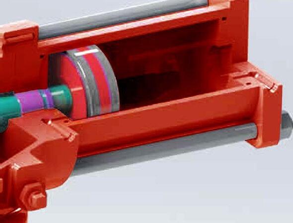
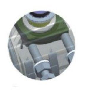
10. Yoke Glide Shaft
The high tensile shaft is enclosed in a self lubricating bronze glide slider preventing roller resistance and ensuring smooth long life due to reduced friction and wear between the yoke arm and pin. A PTFE anti friction coated cover plate prevents debris ingress & retains grease.
11. PTFE Guide Ring
The PTFE Guide prevents metal to metal contact with the cylinder bore, thus ensuring the cylinder is not damaged by the piston whilst also reducing torque as well as ensuring ease of operation.
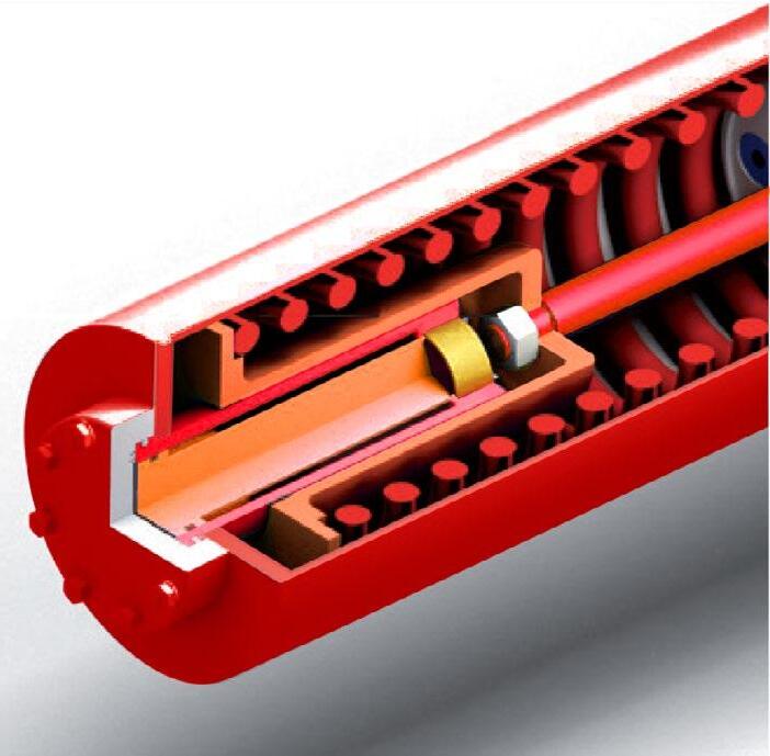
11A. Double Piston Seals
Hydraulic cylinders have double sealing with o-ring and dynamic seal ring to prevent metal to metal contact between clylinder and piston
12. PTFE Lined Cylinder
The Air/Hydraulic Cylinder is PTFE lined to ensure smooth low torque operation over the life of the actuator and also prevent corrosion.
13. Spring Safety
The retaining nut system & cover positively locks and covers the spring module to allow its safe removal and installation, eliminating accidental release of the spring force.
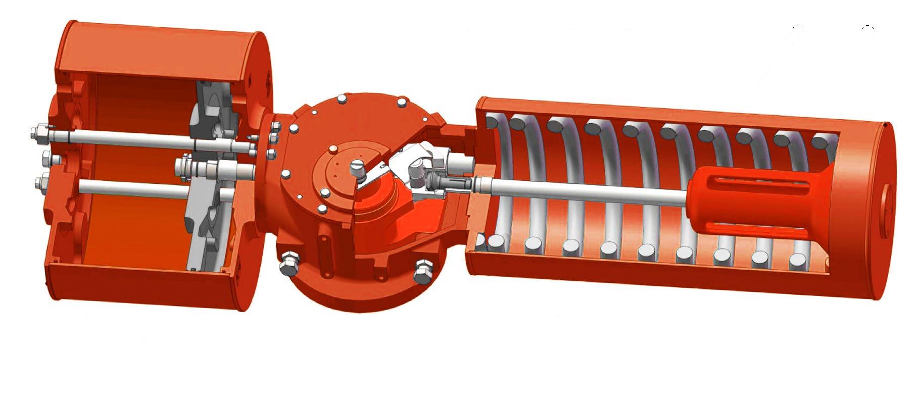
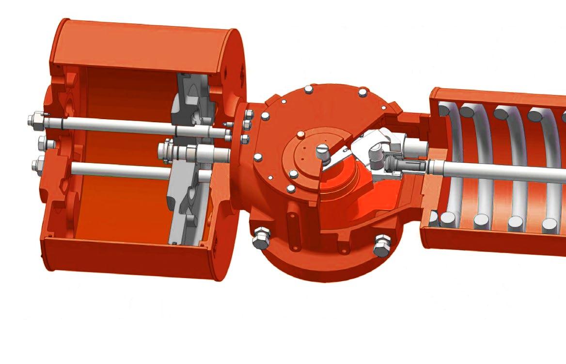
1. Safe Spring Lock
Positively locks the spring module in place under load. Prevents spring module detachment from the drive module.
2. Reduced Wear
The design of connection between the hard chromed piston rod and the guide block compensates for side load deflection and there by reduces wear on the rod, bearings and seals. Connecting rod swivels that connect the piston rod to the guide block compensate for deflection of side loads and reduce wear on seals, bearings and seats (AGP2~AGP9)
3. Standardised Mounting
ISO 5011 base flange and NAMUR mounting configuration allows standardisation of mounting hardware for a wide range of shaft driven accessories.
4. Replaceable Bearings
Replaceable PTFE coated upper and lower torque shaft and yoke pin/ piston rod bearings protect sliding and rotating components, with suitability for either dry or lubricated working conditions.
5. Guide Bar
Hard alloy steel thrust bar and block prevents yoke pin axial movement, transferring axial loads directly to the drive module case.
6. Optional Over-ride
Internal hydraulic over-ride cylinder module for spring-return models doesn’t increase actuator length.
7. Ease of Lifting
All AGP models are equipped with multiple lifting eyes for safe actuator handling during shipping installation and removal.
8. Housing Vent
The main actuator housing incorporates a stainless steel check valve in order to release overpressure.
9. 80°~100° Travel Adjustment
Bi-directional travel stops are integral to the actuator. The stops allow 80° ~ 100° total travel adjustment and are designed to prevent ingress of foreign matter and water.
10. Yoke Roller
A high tensile chrome-moly hard chrome roller rotating in (upper and lower) PTFE coated DU bearings . The top and bottom of the hard chrome alloy steel roller pin is encapsulted in PTFE anti-friction coated bronze cover/retainer plates which reduces friction and minimises wear.
11. Guided Disc
The AGP Series has no external tie bars ensuring corossion resistance. The dual internal hard chromed guide and tie bars centralise the disc throughout its travel ensuring no leakage or wear of the heavy ‘D’ NBR piston seal and ensuring the cylinder is not damaged by the piston whilst also reducing torque as well as ensuring ease of operation.
12. Air Cylinder
The seamless steel Air Cylinder is PTFE/XYLAN lined to ensure smooth low torque operation over the life of the actuator and also prevent corrosion.
13. Spring Module
The retaining nut system & cover positively locks and covers the spring module to allow its safe removal and installation, eliminating accidental release of the spring force. The fully sealed seamless steel
case module is guided by self lubricated alignment bearings and is corossion resistant being grease filled for life with internal and external multi-coat paint systems.
14. Drive Swivels
1000 MPa high tensile alloy steel hard chrome power drive swivels balances radial forces for smooth low wear/low resistance long life.
15. Corrosion Resistant Spring Module
Guided by self-lubricating alignment bearings. Fully enclosed and incorporating safety lock feature. Corrosion resistant to harsh environments. Multi-coat painted and internal grease filled for life.
16. Internal Tie Bars
Hard chromed alloy steel oversize dual internal centralising guided tie bars are corrosion resistant and ensure smooth, long life operaton of the piston and seal.
17. Modular Design
AGP actuators have field serviceable drive, power, spring and override modules. The modules are removeable, serviceable and interchangeable while mounted on the valve.
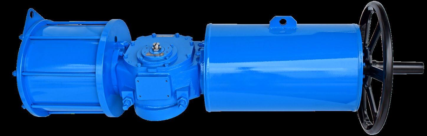
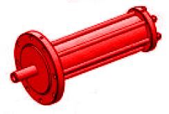
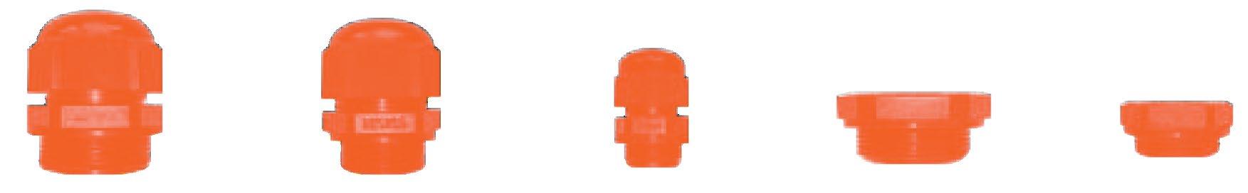
Pneumatic Power Module Model GP
Hydraulic Power Module Model GH or over-ride for Hydraulic Actuators Module
Pneumatic Power Module with Manual Over-ride and/or with extended travel stops
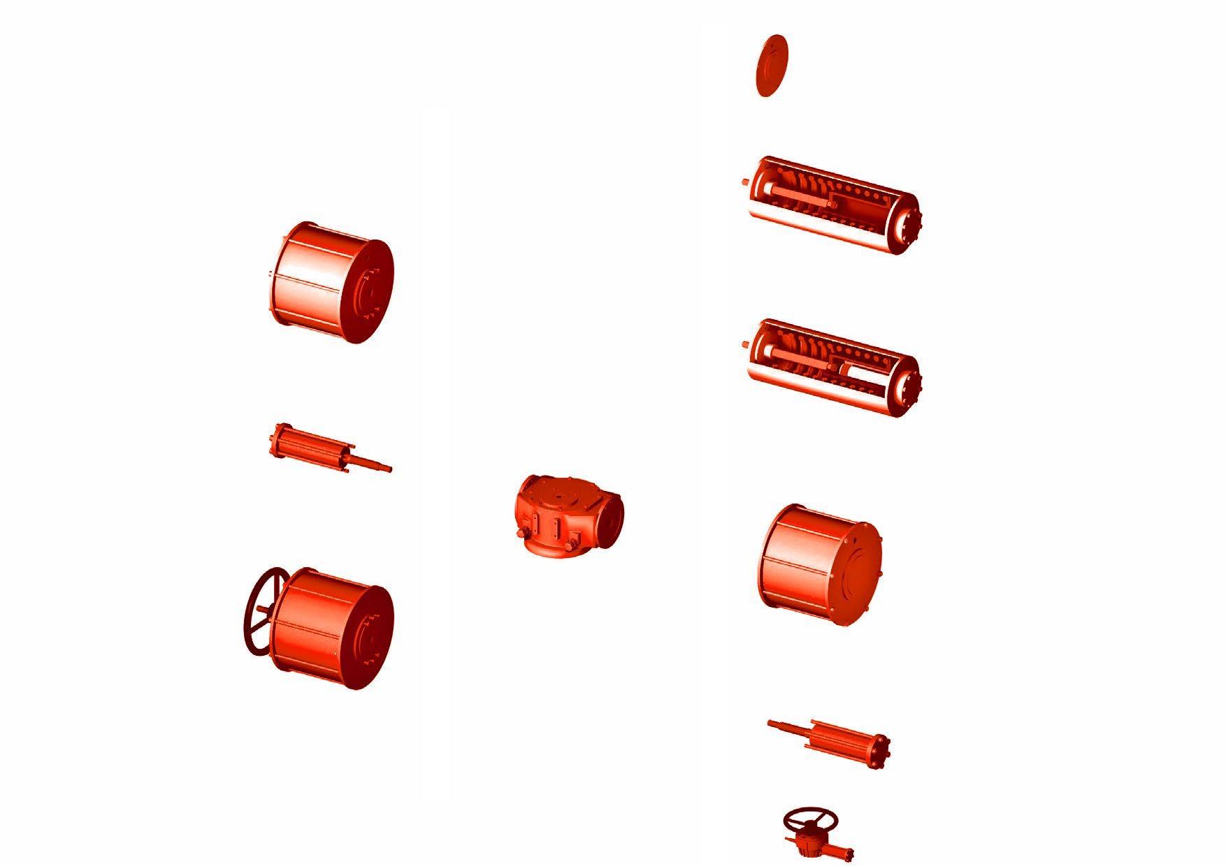
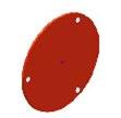
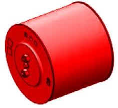
Blind End Cap
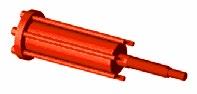
Spring Module
Spring Module with Integral Internal over-ride Hydraulic Cylinder
Pneumatic Power Module
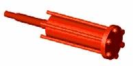
Hydraulic Power Module or Over-ride for Hydraulic Actuator Module
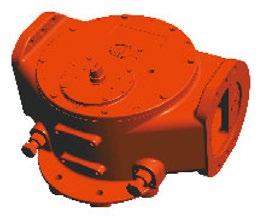
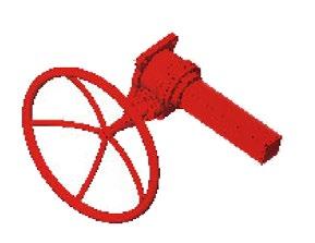
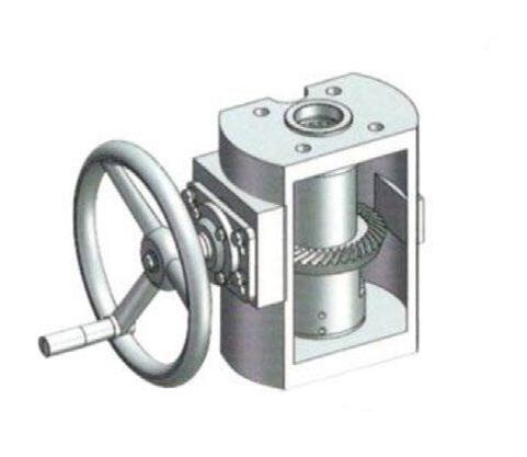
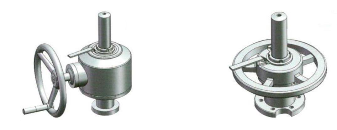
Manual Gear Over-ride
Handwheel Over-ride
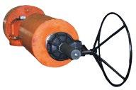
Non-declutchable mechanical override for spring-return models.
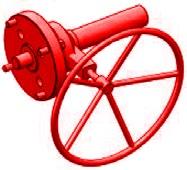
Non-declutchable mechanical override for spring-return models.
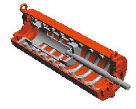
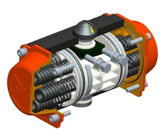
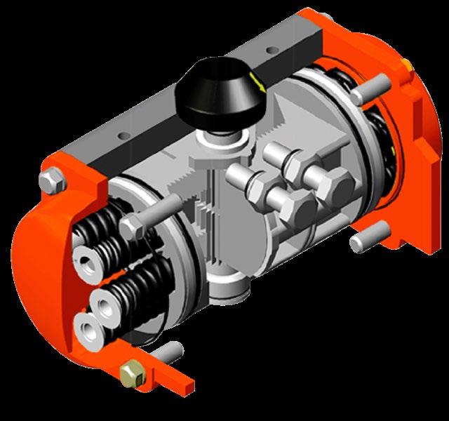
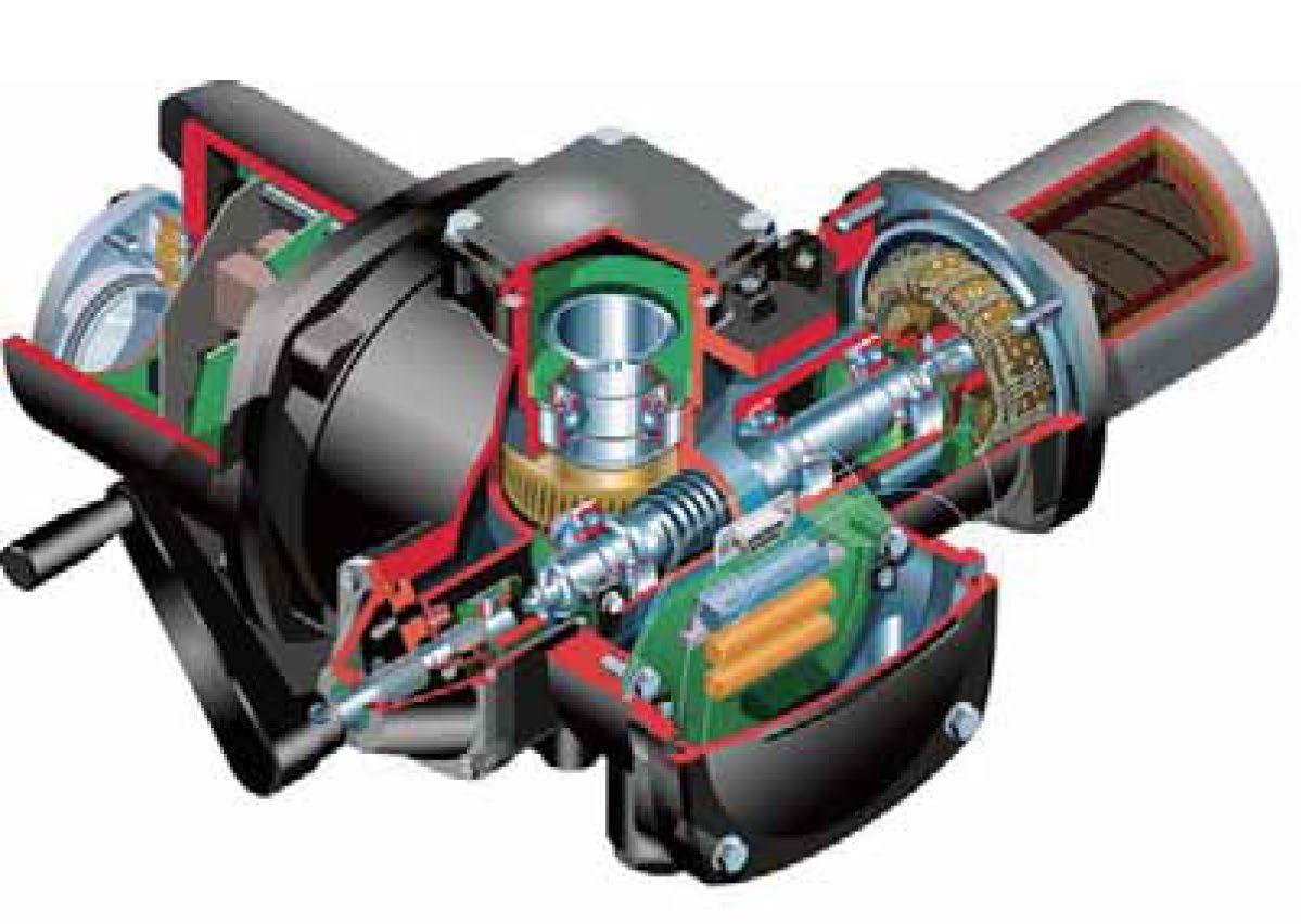
Self-lubricating bearings are used on piston rod, guide bar and other moving parts, which reduces resistance and extends the life of all moving parts.
THRUST (GUIDE) BAR (hard chrome alloy steel) prevents any yoke pin axial movement, and guide block simply transferring axial loads directly to the drive module case, compensating for angular and lateral deflection.
PARA ARM YOKE design connects piston rod with the guide block. This compensates for side load deflection and there by reduces wear on rod, bearings and seals. The fully integral yoke is nitrided.
BEARINGS provide protection for sliding and rotating components, suitable in both dry and lubricated working conditions.
YOKE SLIDER The self lubricated bronze-copper slider block around the yoke pin prevents rolling resistance and wear ensuring a long life and smooth action.
A PTFE anti-friction coated bronze retainer cover plate encapsulates the top to ensure no debris ingress and retain grease, reducing the friction normally encountered in a conventional design between yoke arm and pin minimising the wear and extending working life.
INTERNAL O-RINGS Maximum water and corrosive elements protection
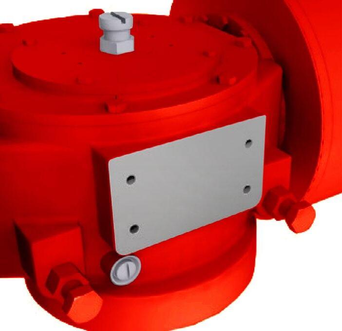
NAMUR mounting configuration for use with a wide range and sizes of shaft driven accessories.
THREADED CONNECTIONS in front and the back side of the body enables attachment of control panels.
RELEASES OVERPRESSURE Integral vent check valve releases overpressure in the actuator main housing isolating the chamber from corrosive vapours and water.
Override)
INTERNAL HYDRAULIC CYLINDER (Optional) for manual hand pump override. Internal hydraulic over-ride cylinder module for spring-return models doesn’t increase actuator length.
SAFE SPRING LOCK (Supplied with Hydraulic Over-ride option), positively locks the spring module in place under load. Prevents spring module detachment from the drive module.
PISTONS SEALS
Cylinders have double sealing with o-ring and dynamic seal ring to prevent metal to metal contact between clylinder and piston.
LINED CYLINDER
The Air Cylinder is PTFE/XYLAN lined ensuring smooth low torque operation over the life of the actuator and also prevent corrosion.


PISTONS SEALS
Double sealing, with o-ring and dynamic seal ring to prevent metal to metal contact between the piston and the cylinder
LINED CYLINDER
The inner surface of cylinder is coated with PTFE, to prevent resistance and self-lubricating
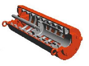
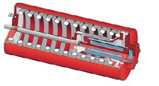
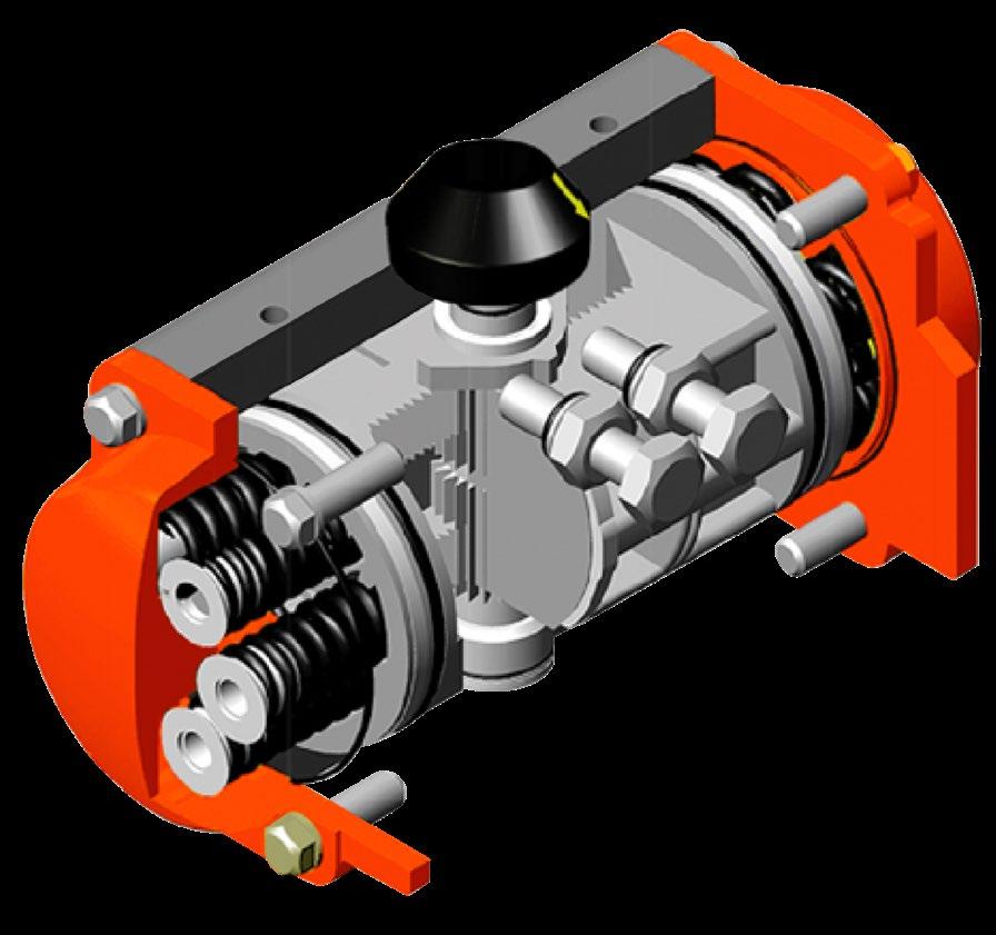
Self-lubricating bearings are used on piston rod, guide bar and other moving parts, which reduces resistance and extends the life of all moving parts.
THRUST (GUIDE) BAR (hard chrome alloy steel) and guide block prevents any yoke pin axial movement, simply transferring axial loads directly to the drive module case, compensating for angular and lateral deflection.
PARA ARM YOKE design connects piston rod with the guide block. This compensates for side load deflection and there by reduces wear on rod, bearings and seals. The fully integral yoke is high frequency quench hardened to HRC 50.
BEARINGS throughout provide protection for sliding and rotating components, suitable in both dry and lubricated working conditions.
YOKE ROLLER The high tensile alloy steel hard chrome roller rotates inside two PTFE coated bronze DU bearings to reduce friction and minimise wear. Furthermore the top and bottom of the roller pin is encapsulated under a semi flexible anti-friction PTFE coated bronze retainer/cover plates which retains grease and prevents debris ingress.
PTFE coated bronze slider cover plate encapsultes the roller pin ensuring smooth running and long life.
INTERNAL O-RINGS Maximum water and corrosive elements protection.
NAMUR mounting configuration for use with a wide range and sizes of shaft driven accessories.
THREADED CONNECTIONS in front and the back side of the body enables attachment of control panels.
RELEASES OVERPRESSURE Integral vent check valve releases overpressure in the actuator main housing isolating the chamber from corrosive vapours and water.

INTERNAL HYDRAULIC CYLINDER (Optional) for manual hand pump override. Internal hydraulic over-ride cylinder module for spring-return models doesn’t increase actuator length.
SAFE SPRING LOCK
under load. Prevents spring module detachment from the drive module.
The AGP has no external tie bars which ensures a high level of corossion resistance. The dual internal centralising hard chrome alloy steel guide and tie bars ensures a much smoother centralised motion and long life without axial wear loading on piston seal, bearings and yoke components. The steel air cylinder case is is fully o-ring sealed.
The Air Cylinder
and also prevent corrosion.
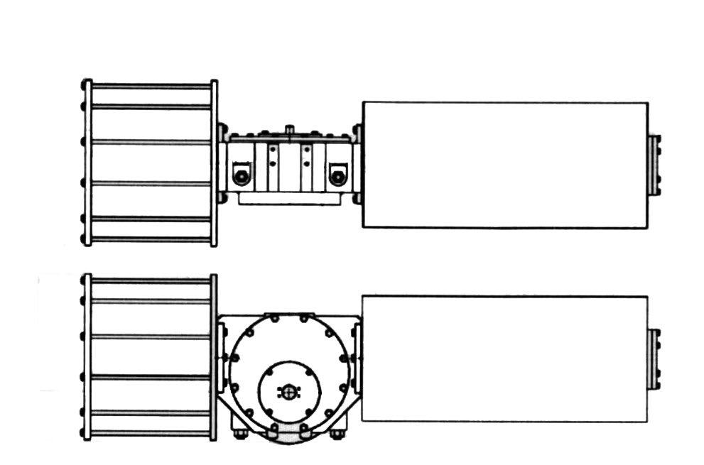
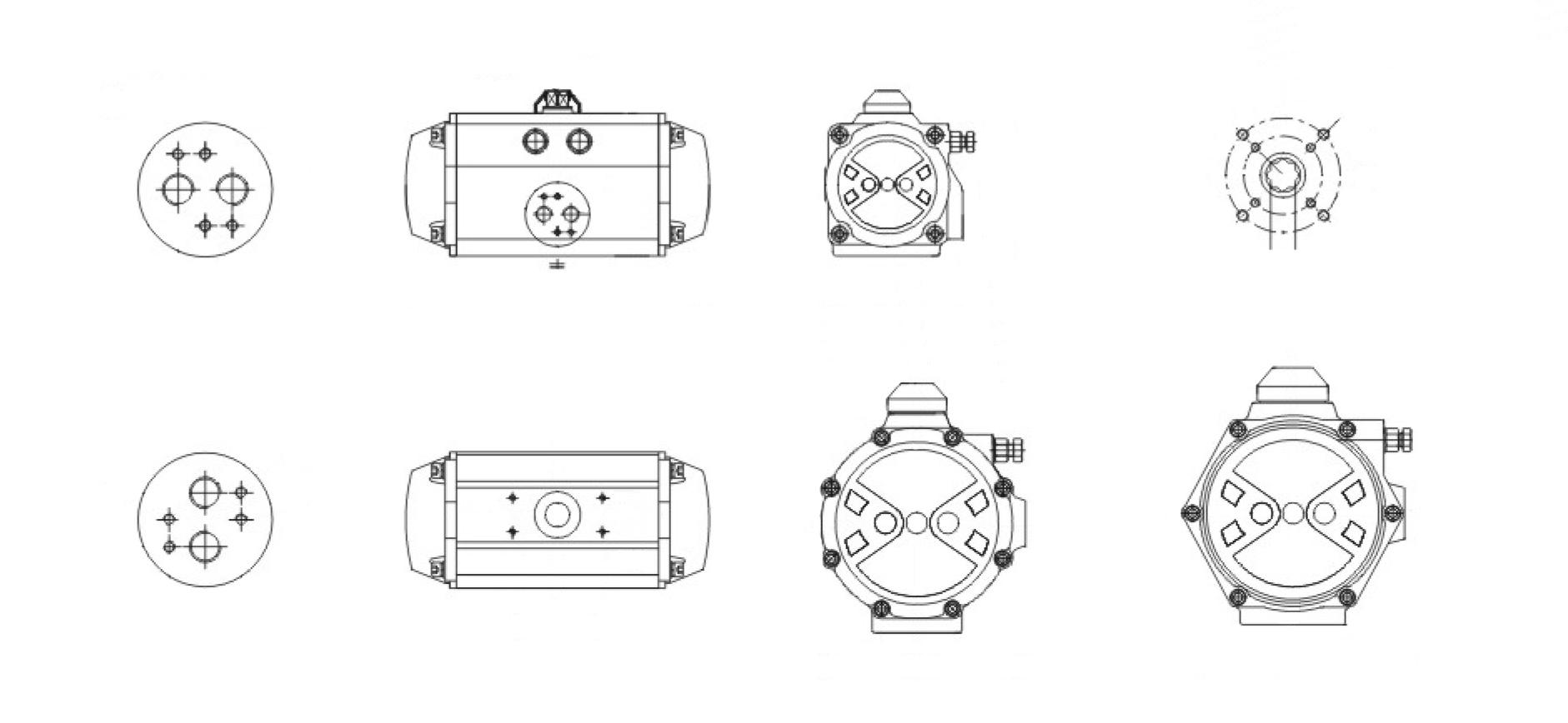
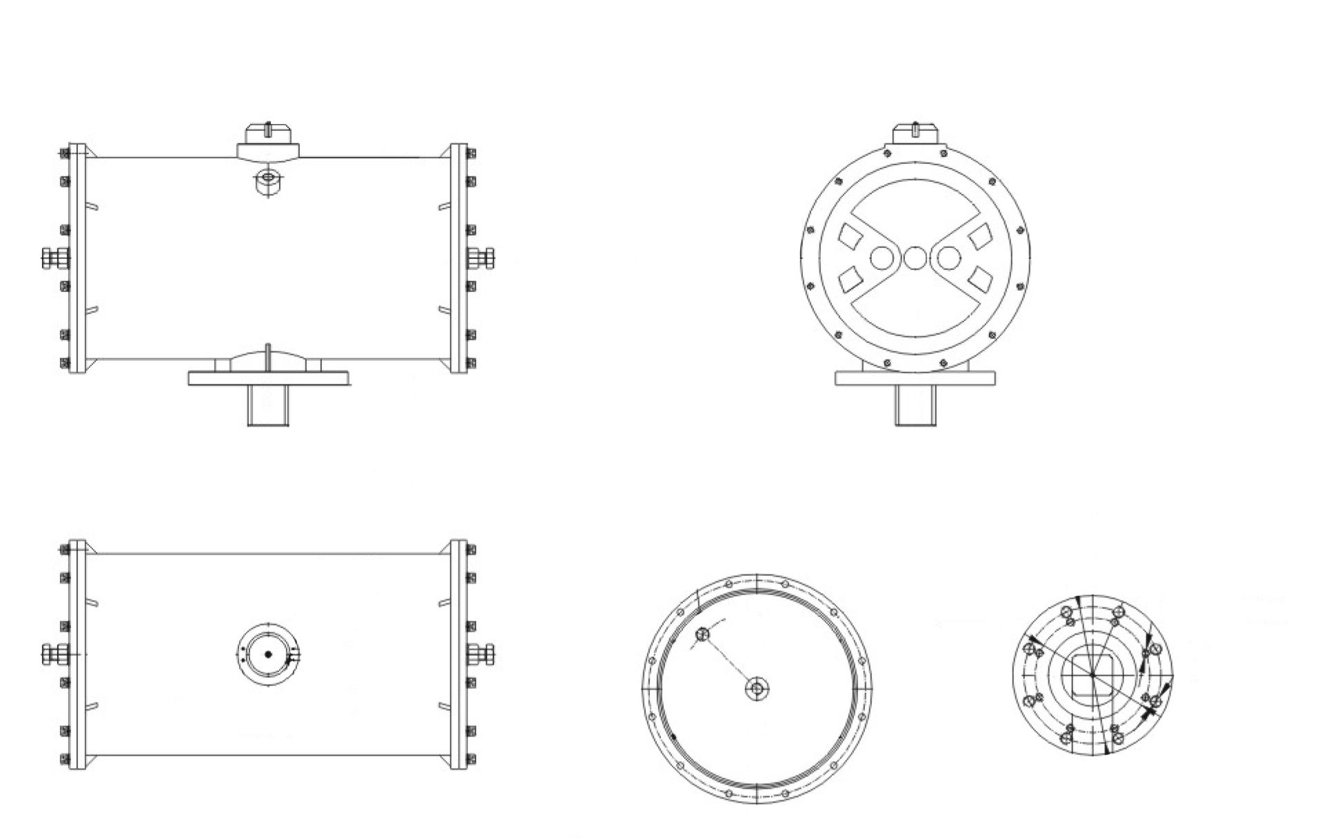
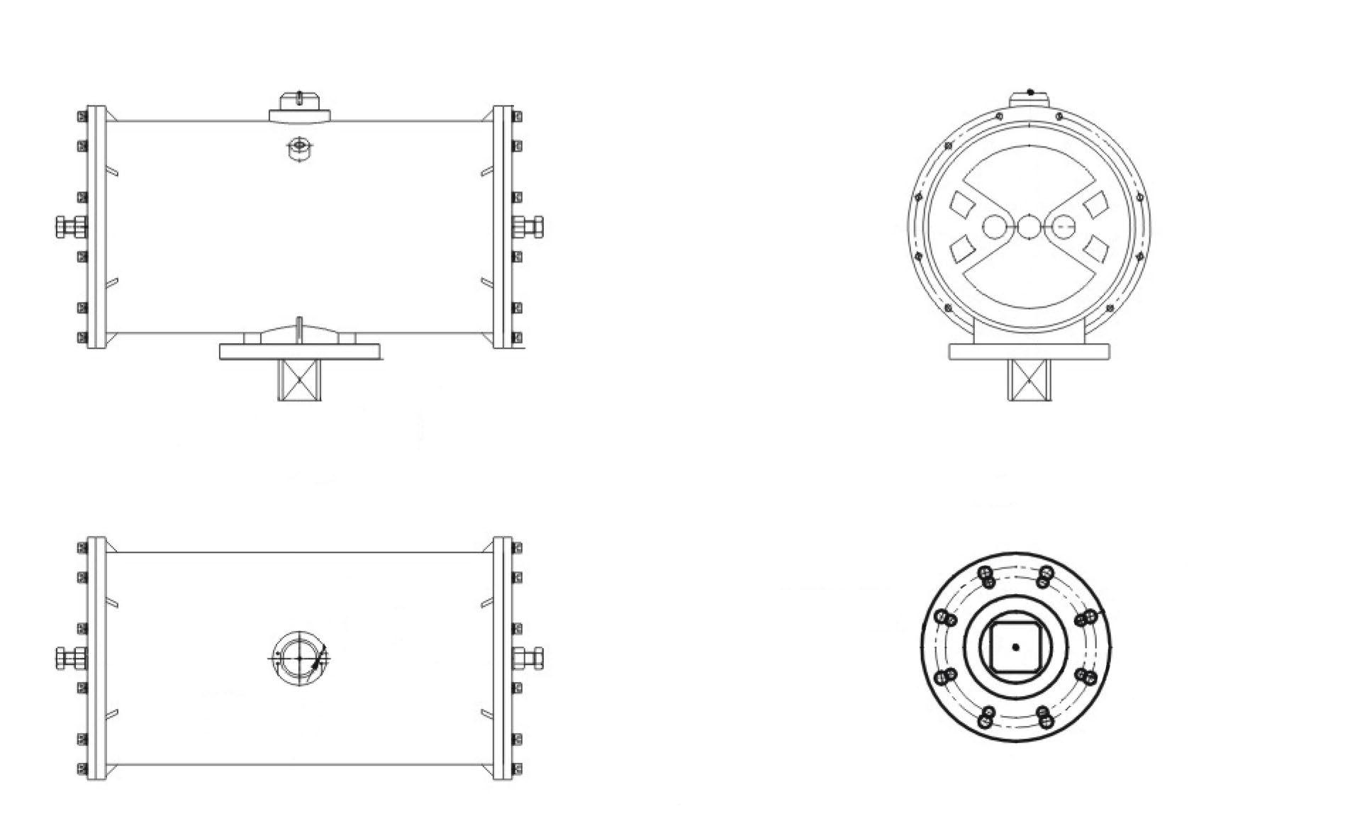
G RANGE PNEUMATIC
Indicative dimensions only, refer to as built drawing as dimensions vary according to configuration.
General overview only, refer to drawing for dimensions. *Refer to drawing.
Indicative dimensions only, refer to as built drawing as dimensions vary according to configuration.
General overview only, refer to drawing for dimensions. *Refer to drawing.
BTO = Break To Open Torque (Air Start)
RUN = Running Minimum (Half-Stroke Torque)
ETO = End To Open Torque (Air End)
BTC = Break To Close Torque (Spring Start)
ETC = End To Close Torque (Spring End)
BTO = Break To Open Torque (Air Start)
RUN = Running Minimum (Half-Stroke Torque)
ETO = End To Open Torque (Air End)
BTC = Break To Close Torque (Spring Start)
ETC = End To Close Torque (Spring End)
SPRING RETURN TORQUES (Nm) - AIR SUPPLY 4.5 BAR
BTO = Break To Open Torque (Air Start)
RUN = Running Minimum (Half-Stroke Torque)
ETO = End To Open Torque (Air End)
BTC = Break To Close Torque (Spring Start)
ETC = End To Close Torque (Spring End)
BTO = Break To Open Torque (Air Start)
RUN = Running Minimum (Half-Stroke Torque)
ETO = End To Open Torque (Air End)
BTC = Break To Close Torque (Spring Start)
ETC = End To Close Torque (Spring End)
GP48S-1000
BTO = Break To Open Torque (Air Start)
RUN = Running Minimum (Half-Stroke Torque)
ETO = End To Open Torque (Air End)
BTC = Break To Close Torque (Spring Start)
ETC = End To Close Torque (Spring End)
BTO = Break To Open Torque (Air Start)
RUN = Running Minimum (Half-Stroke Torque)
ETO = End To Open Torque (Air End)
BTC = Break To Close Torque (Spring Start)
ETC = End To Close Torque (Spring End)
BTO = Break To Open Torque (Air Start)
RUN = Running Minimum (Half-Stroke Torque)
ETO = End To Open Torque (Air End)
BTC = Break To Close Torque (Spring Start)
ETC = End To Close Torque (Spring End)
BTO = Break To Open Torque (Air Start)
RUN = Running Minimum (Half-Stroke Torque)
ETO = End To Open Torque (Air End)
BTC = Break To Close Torque (Spring Start)
ETC = End To Close Torque (Spring End)
(ml)
GH10-40SR1 110
GH10-40SR2 110
GH10-50SR2 150
GH10-50SR3 150
GH10-60SR3 235
GH12-50SR1 180
GH12-60SR1 285
GH12-50SR2 285
GH12-60SR2 285
GH12-70SR2 405
GH14-60SR1 310
GH14-70SR1 455
GH14-60SR2 310
GH14-70SR2 455
GH14-70SR3 455
GH14-80SR3 620
GH14-100SR3 1010
GH16-70SR1 520
GH16-80SR1 720
GH16-90SR1 950
GH16-80SR2 720
GH16-90SR2 950
GH16-100SR2 1200
GH16-80SR3 720
GH16-100SR3 1200
GH16-110SR3 1480
GH25-90SR1 1100
GH25-100SR1 1420
GH25-110SR1 1770
GH25-100SR2 1420
GH25-110SR2 1770
GH25-120SR2 2150
GH25-100SR33 1420
GH25-120SR3 2150
GH25-140SR3 3000
GH30-110SR1 1980
GH30-120SR1 2450
GH30-140SR1 3460
GH30-120SR2 2450
GH30-130SR2 2950
GH30-150SR2 4050
GH30-130SR3 2950
GH30-150SR3 4050
GH30-170SR3 5300
GH35-130SR1 3490
GH35-150SR1 4920
GH35-170SR1 6500
GH40-170SR1 7180
GH40-190SR1 9400
GH40-220SR1 13100
GH40-190SR2 9400
GH40-220SR2 13100
GH40-245SR2 16500
GH48-190SR1 10800
GH48-220SR1 15200
GH48-245SR1 19300
GH48-220SR2 15200
GH48-245SR2 19300
GH48-270SR2 23800
GH48-245SR3 19300
GH48-270SR3 23800
GH48-290SR3 27900
GH60-220SR1 19000
GH60-245SR1 24500
GH60-270SR1 30600
GH60-245SR2 24500
GH60-270SR2 30600
GH60-320SR2 44500
GH35-150SR2 4920 - -
GH35-170SR2 6500
GH35-190SR2 8350
GH35-170SR3 6500
GH35-190SR3 8350
GH35-220SR3 11500
= Jack Screw
= Jack Screw Manual Over-ride
= Extended Travel Stop HY = Hydraulic Over-ride
= Manual Gear Over-ride
Blank = StandardTemperature (NBR) (-25~100°C) LT = Low Temperature (HNBR) (-45~80°C)
HT = High Temperature (Viton) (-20~130°C)
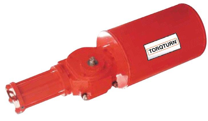
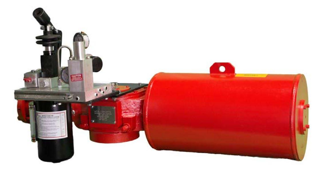
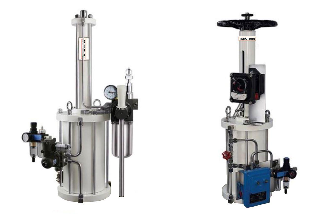
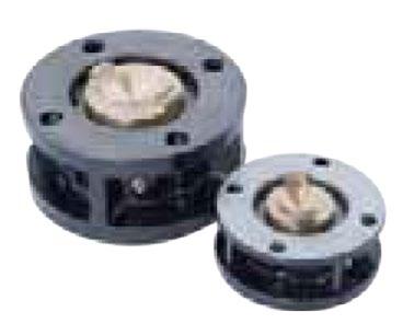
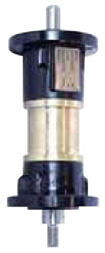
G-GHA / FEP pneumatic hydraulic actuators are produced in linear and quarter-turn.They use the source gas pressure in the line as the energy source to operate the valve.
These actuators therefore require no independent power source and allow variable torque and speed.
APPLICATIONS
Quarter-turn ball valves, plug, butterfly as well as linear valves.
SPECIFICATIONS
Ability to communicate position provision of manual hydraulic hand pump over-ride and hydraulic remote control.
IB67 Construction
Eex dIIB T4 explosive protection Anti corrosive paint.
1 = Without control (calibrated nozzle)
3 = Adjust with electric
1 = Local
2 = Wired
3 = Local +
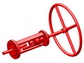
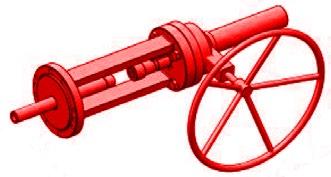
ACB SERIES
PISTON TYPE SCOTCH YOKE
FEATURES AND BENEFITS
• Scotch yoke design using precision bearings eliminates the usual dead zone present in other yoke mechanisms, providing the maximum torque output at beginning and end of stroke.
• SIL 2 and SIL3
• Travel stops located at the centre of the piston rod eliminates side loading to the output shaft.
• ISO 5211 standard mounting.
• Top of the actuators have NAMUR mounting design, for ease of mounting limit switch and positioner
• ACB series actuators are available with different shafts on request (male or female)
TECHNICAL DATA
Maximum supply pressure 0.8MPa
Rated supply pressure 0.3 ~ 08MPa
Temperature
Standard -20ºC to 80ºC
High Temperature -10ºC to 150ºC
High Temperature -45ºC to 80ºC
Angular rotation 90 degrees ± 10 degrees
GENERAL APPLICATION
The ACB is a rugged high quality reliable actuator. ACB series actuators are normally used for remote control of any quarter-turn application: ball, butterfly, rotary plug or damper style valves, etc. Used in oil and gas, chemical process, food and beverage, iron and steel, off-shore marine, pharmaceutical, power, pulp and paper, and textile industries.
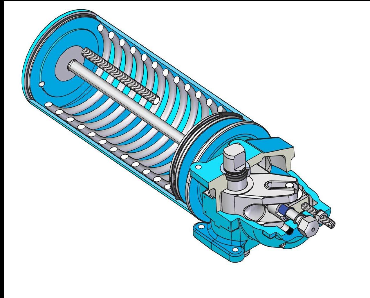
Design
No moving parts on the outside. Safe and relatively maintenance free. Heavy hard chromed alloy steel internal tension rod, no external tie bars. A flexible X style "quad seal" seals the piston to the cylinder wall ensuring a long leak free life.
PTFE/Xylan coated cylinder ensures a smooth surface for the piston seal to glide, ensures a long lasting, low torque, corrosion resistant smooth surface.
Environmental Protection
Independently certified to IP67M water ingress protection to prevent corrosion. Water ingress on the torque shaft, is prevented by using a separate pressure seal and weather resistance between the torque shaft and body.
A multi layer paint system and grease coated internal components ensure a long life. The ACB is fully o-ring sealed (no gaskets) with 4 seals, two seals on the lower shaft, an outer seal to protect the bearing area, and primary inner seal from the environent.
Spring Preload
The ACB actuators use a preloaded spring and has a special locking device.
OUTPUT TORQUE (Nm) (SYMMETRICAL) SINGLE ACTING - SPRING RETURN FAIL CLOSED
OUTPUT TORQUE (Nm) DOUBLE ACTING (SYMMETRICAL)
DIMENSIONS - DOUBLE ACTING
The model with
DIMENSIONS - SPRING RETURN
ACB-VTS04-220-SRxFC
ACB-VTS04-260-SRxFC
ACB-VTS04-260-SRxFO 212 273 98 84 40
Note:
1. The "x" in the model in the table indicates the spring number, which is selected according to the required torque but does not affect dimensions.
2. Fail open (FO) and fail closed (FC) dimensions are the same. The actuator stem position shown in the drawing above is fail closed (FC).
The position of fail open (FO) actuator is symmetrical to the output shaft relative to the centre line AA.
3. The volume is defined as the water volume of the whole air chamber after the actuator spring is fully
The RP Series rack & pinion pneumatic actuator has been designed, developed and tested incorporating the latest technology and materials available, with some innovative design features. As a result of this product research we have obtained a high grade product with the following characteristics:
• Reliability
• High performance
• Wider product range permitting a more economical sizing selection.
• Innovative and patented universal drive shaft and multifunction position indicator
• Full compliance with latest worldwide specifications
• A wide selection of highest levels of corrosion protection technology
• Aesthetically compact and modern style with no external cavities to avoid deposit build up.
PRODUCT SPECIFICATION
Product Code
Chamber 50, 100
Acting Way
“DA” double acting (DA)
“SR” Single acting (spring return)
Operating temperature
Normal temperature NT (Slightly) temperature -20°C~+80°C
Low temperature LT temperature -40°C~+80°C
High temperature HT temperature -15°C~+150°C
INSTRUCTIONS
1. Operating media
Dry or lubricated air or inert / non-corrosive gases on condition that they are compatible with internal actuator parts and lubricant. The operating media must have a dew point equal to -20°C (-40°F) or at least 10°C below the ambient temperature. The maximum particle size must not exceed 30 µm
2. Supplying Pressure
For Double Acting and spring Return actuators the maximum supply pressure is 8 Bar (116PSI). Minimum supply pressure is 2.5 Bar (36PSI)
3. Operating Temperature
• Standard product from -20°C (-4°F) to +80°C (+176°F)
• Low temperature LT actuator with VMQ ‘O’ Rings from -40°C (-40°F) to +80°C (+176°F)
• High temperature HT actuator with FPM ‘O’ Rings from - 15°C (+5°F) to +150°C (+302°F)
Caution: For low and high temperature service. Special lubricant is required. Please contact APV for each application. High and low temperature will vary changing the output torque of the actuator.
4. Stroke
There is ±5° adjustable angle at the position of open and end of close.
5. Operating Time
See Technical Data Sheet
6. Lubrication
Actuators are factory lubricated for the life under normal operating conditions. The standard lubricant is suitable for use from -20°C (-4°C) +80°C (+176°F)
7. Construction
Twin piston rack & pinion actuator design suitable for both indoor & outdoor installation.
8. Protection and Corrosion Resistance
Actuators are supplied with corrosion protections for normal environments. For severe duties select from the protection level table or contact APV.
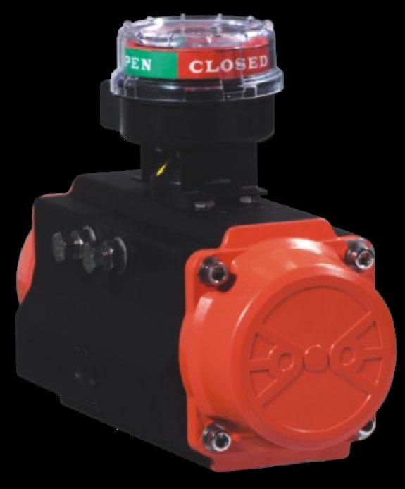
Indicator
Position indicator with NAMUR is convenient for mounting accessories such as Limit Switch box, Positioner and so on.
The pinion is high-precision and integrative, made by nickelledalloy steel, full conform to the latest standards of ISO 5211, DIN33337, NAMUR. The dimensions can be customised and the stainless steel is available.
Cylinder
According to the different requirements, the extruded aluminium alloy ASTM6005. Body also optionally treated with hard anodised powder polyester paint. PTFE or Nickel plated.
Ends Caps
Die-casting aluminium powder polyester painted in different colours, PTFE or Nickel plated.
NBR rubber O-rings provide trouble-free operation at standard temperature ranges. For high and low temperature applications Viton or Silicon.
Pistons
The twin rack pistons are made from Die-casting aluminium treated with hard anodised or made from cast steel with galvanisation, symmetric mounting position, long cycle life and fast operation, reversing rotation by simply inverting the pistons.
Travel adjustment
The two independent external travel stop adjustment bolts can adjust ±5° at both open and close directions easily and precisely
High performance springs
Preloaded coating springs are made from high quality material for resistant to corrosion and longer service life, which can be demounted safely and conveniently to satisfy different requirements of torque by changing quantity of springs.
Bearings & Guides
Made by low friction and long-life compound material, avoid the direct contacting between metals.
PARTS & MATERIALS RP50~RP400
DIMENSIONS RP500
DIMENSIONS RP600
RP300-600 Refer to separate specification sheet
Double-acting
Torqturn reserves the right to amend the technical parameters
Single-acting (Spring Return)
Counter Clock Wise
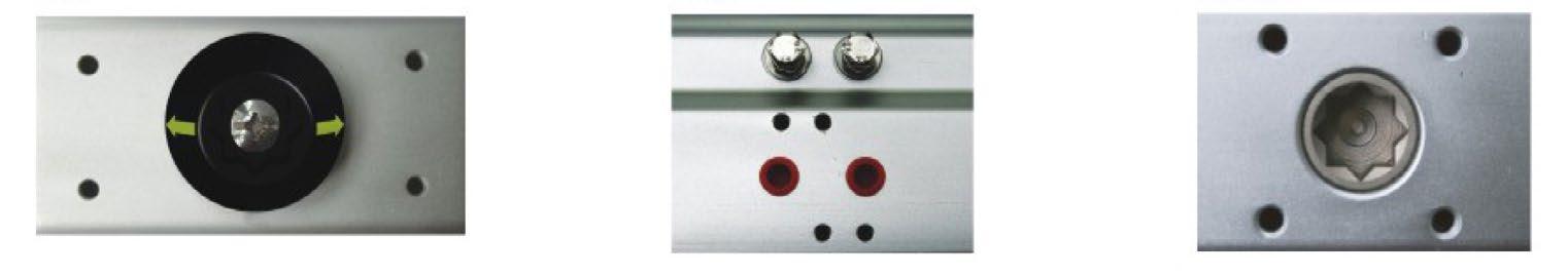
The side connection conforms to the VDI/VDE 3845 NAMUR standard and can be installed to the solenoid valve directly. The top connection conforms to VDI/VDE 3845 NAMUR standard and the limit switch or positional and solenoid can be installed directly. The bottom connection conforms to ISO 5211 and DIN3337 standard and can be installed on the valve directly. (Star hole and square hole can be chosen according to the requirements)

Each actuator is marked with a serial number, air connection and bottom mounting holes are marked for easy track and distinction.
Top mounting pad configuration is in accordance with VDI/VDE 3845 Namur specification in order to permit simple and easy installation of the ancillary like switch boxes and positioners. APV can supply many different types of switch boxes and positioners for any application.
Air supply connection is in accordance with VDI/VDE3845 Namur specification to provide simple and easy solenoid valve installation direct mount avoiding piping and fittings. APV can also supply Namur solenoid valves: 5/2 and 3/2 way in all standard voltages, D.C or A.C.
1 Ancillaries installation without multi-function indicator.
The actuator can be supplied upon request with a NAMUR that replaces the standard indicator and has the Namur drive slot permitting:
1 Accessories such as limit switch and positioner
2 Indicating the position of actuator via the Namur slot
3 Manual operation in emergency
4 Operating at high temperature.
2 External stroke adjustment
A great saving of time is achieved, when mounting the actuator on the valve, through the service friendly adjustment of both end positions with precise cam system. The rotation angle is easily changeable with a special cam system. Safety for emergency cases is possible through blocking of the actuator. This new feature can be used by simply changing the screw into a longer one.
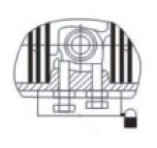
3 Lock-out capability in full open or full-closed position
The actuator offers an economical solution when it is required to lock the Actuator in the full-open (90°) or fully closed (0°) position. The actuator can be supplied with a Special bolt and locking device to permanently lock the actuator in position by using a padlock and prevent unwanted operation.
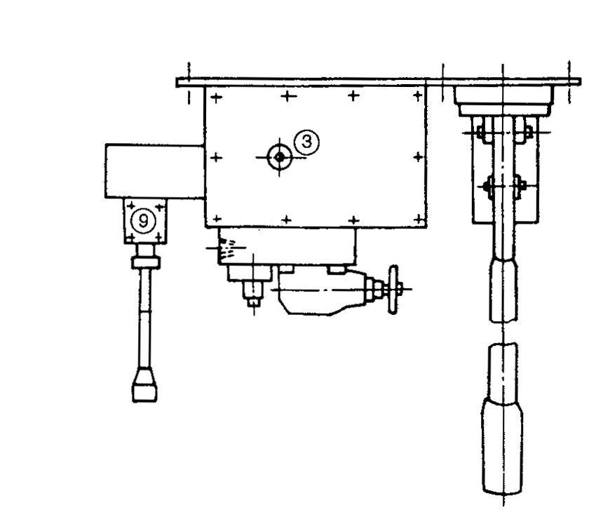
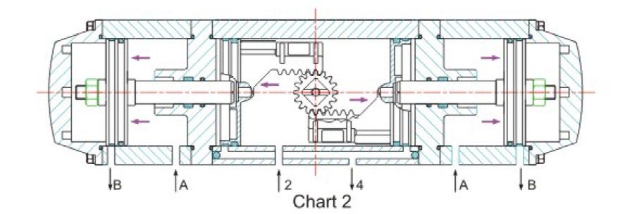
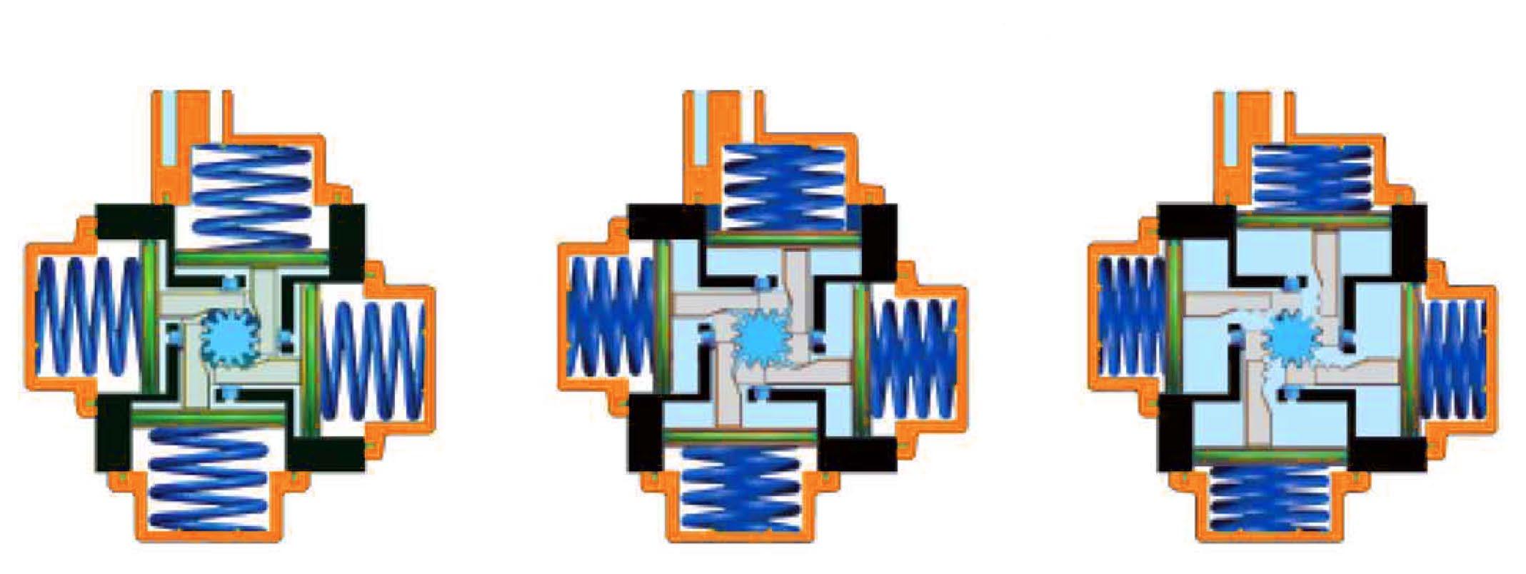
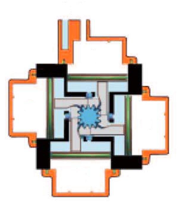
Three position Torqturn actuator provides an operation of 0°, 45°, 90° or 0°, 90°, 120° and 180°. The midway position is achieved by a mechanical stop of movement of the 2 auxiliary pistons.
The midway stop positions are adjustable. Example: 90° actuator can provide 20°, 30°, 50°, 70° etc.
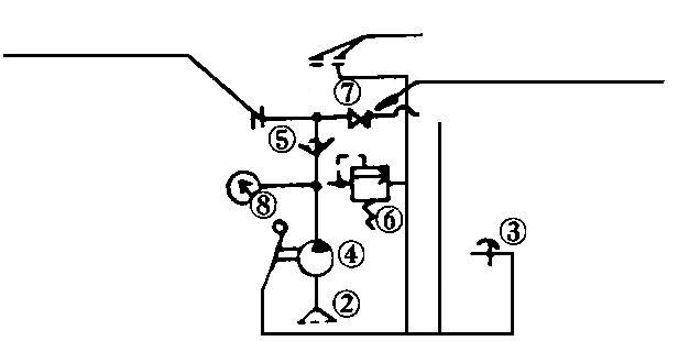
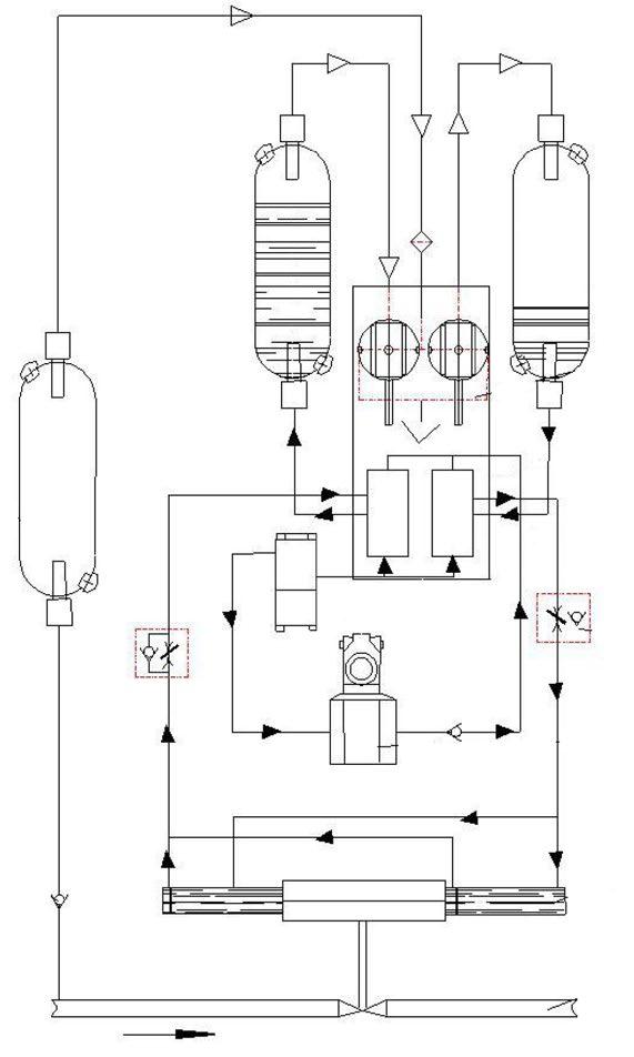
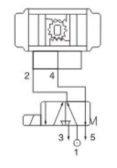
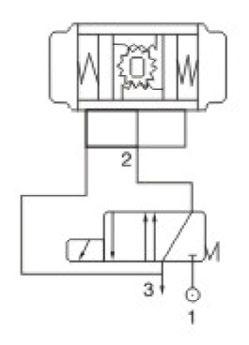
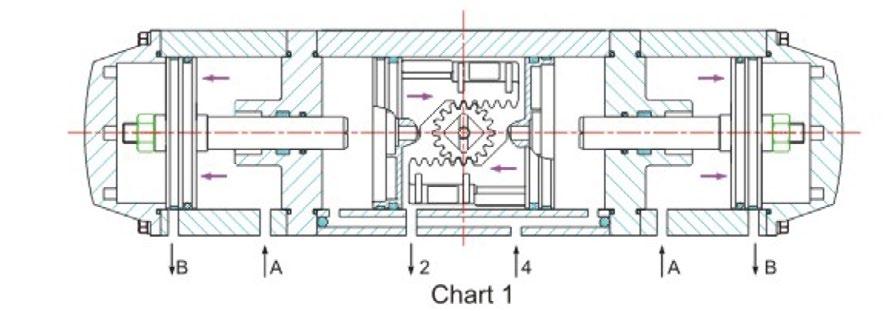
The following is the principle of valve operation:
1. Fully Closed Position
From Chart 1 we can see that this position is obtained when air is supplied to port 4 and port 2 is in the state of exhaust air.
2. Fully Open Position
From chart 2 we can see that this position is obtained when air is supplied to port 2 and port A, meantime, port 4 and port B are in the state of exhaust air.
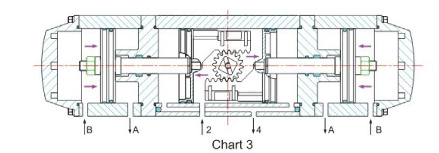
3. Midway Position
From chart 3 we can see that this position is obtained when air is supplied to port 2 and port B, meantime, port 4 and port A are in the state of exhaust air. In fact the midway position is achieved by a mechanical stop of movement on the two auxiliary pistons.
ACCESSORIES AVAILABLE
1. Connecting Brackets
2. Couplings
3. Solenoid Valves
4. Switch Boxes
Torqturn reserves the right to amend the technical parameters
5. Proximity Sensors
6. Gear Boxes
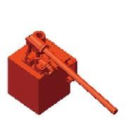
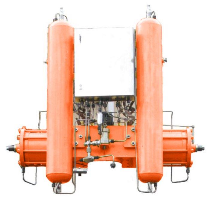
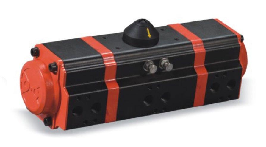
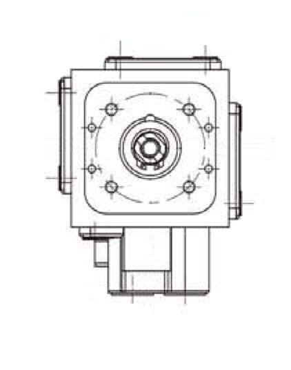
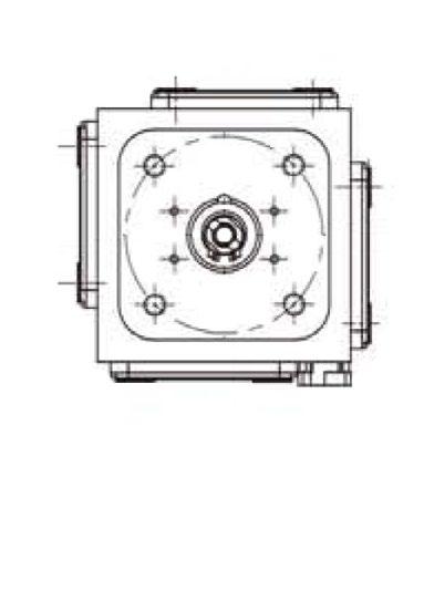
The ATZDF actuator is a quarter-turn rack & pinion pneumatic actuator that doubles the torque of standard pneumatic actuators. The superior performance is achieved by Torqturns four piston design, which generates torque around a centrally located piston. This produces double the power for the same size actuator or half the size for the same amount of torque.
The ATZDF has four small cylinders, one located on all four sides. The smaller pinion and shorter travel distance of the pistons in the ATZDF require less air pressure than a larger double piston actuator to produce the same torque output. This result is faster response times for emergency shutdown, applications as well as lower air pressure for operation and reduced maintenance.
TECHNICAL SUMMARY
Pressure range
20-120 PSI (1.5 - 8 bar) for Double Acting (DA) actuators
30-120 PSI (2 - 8 bar) for Spring Return (SR) actuators Style
Compressed gas Air, Nitrogen, CO2, Natural gas (sweet)
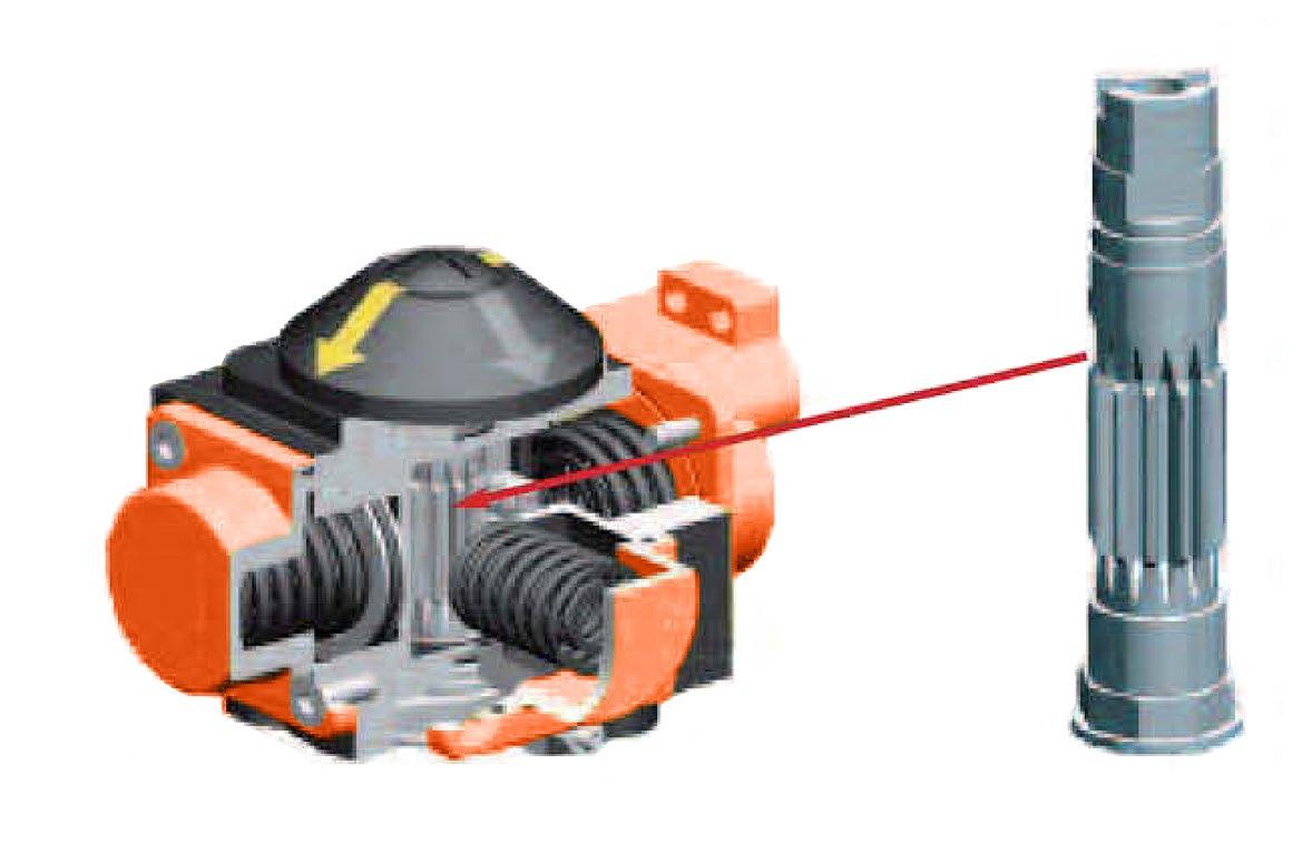
The Torqturn Pneumatic Actuator Series 4x4 supplies more than double the torque of conventional rack and pinion actuators. That’s because it has four pistons generating torque around a centrally located pinion. With more pistons in the actuator, it allows their diameter to be smaller while generating higher torque. At the same time, it means the size of the actuator can be more compact, reducing weight and avoiding stem wear that may be caused by imperfect mounting. With four small cylinders each located on one of four sides of the unit and at a given air pressure, the 4x4 produces the same torque output as double piston models using smaller diameter pistons and a narrower pinion. Thanks to the narrower pinion, the pistons travel shorter distances so that they can move faster from one position to the next.
The cube shape coupled with pistons travelling shorter distances minimises size requirements while maximising torque output. At the same time, shorter piston travel and compact size greatly reduces pressure requirements compared to other designs and results in reduced energy expenditures.
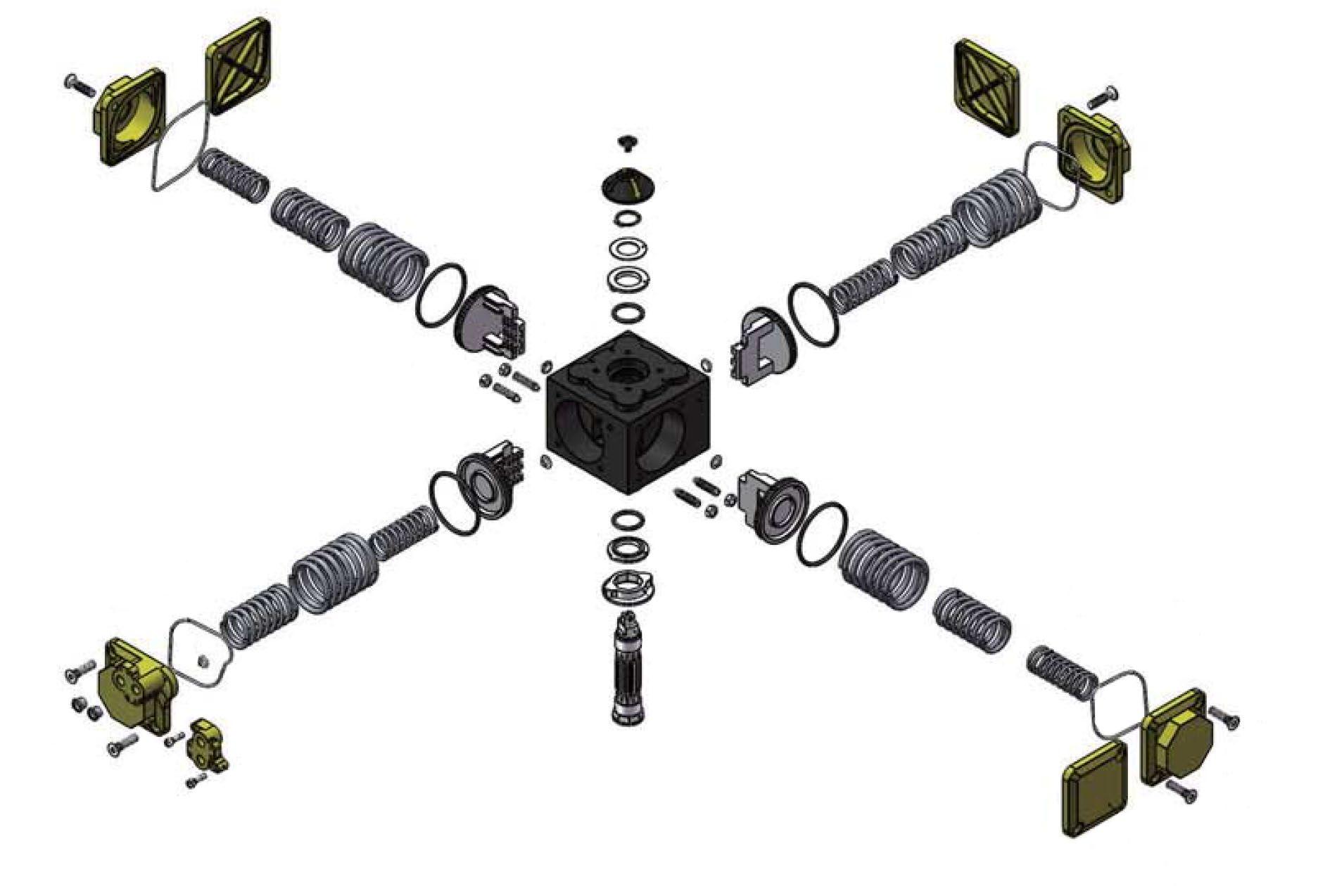
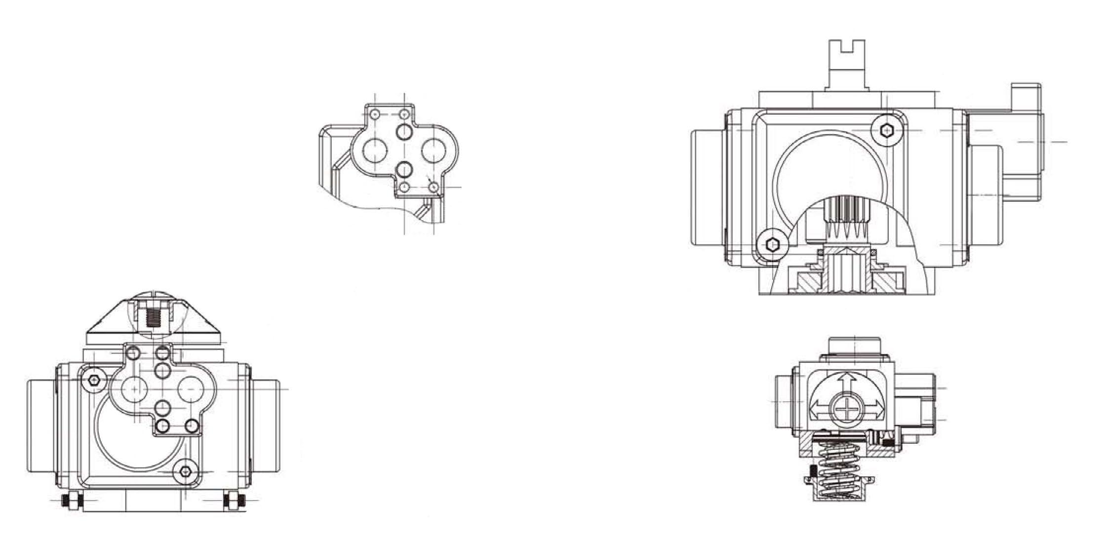
Because of the four-cylinder design, the 4x4 has many more spring combination possibilities than double piston actuators removing the need to compromise. This means better solutions under any air pressure requirement. Each chamber can use up to three different spring sizes which nest between the covers and pistons and align by centreing rings. Also, springs are wound in opposite directions to avoid tangles during operation.
For superior corrosion resistance, the body and covers are anodised internally and externally. In addition, they have an external epoxy base layer and a second polyurethane paint layer further reduces corrosion in demanding applications. Extended spray wash downs do not create corrosion problems for the actuator.
Travel stops can be adjusted by four studs at the base of the actuator.
The studs are opposed from each other so no unequal forces are generated, the stop design allows for -/+ 5° adjustment in both opening and closing rotations. Mid-stroke stop points can be achieved with longer studs.
Blowout proof and Acetal support pad in body maintains proper contact of the piston racks to the pinion at all times.
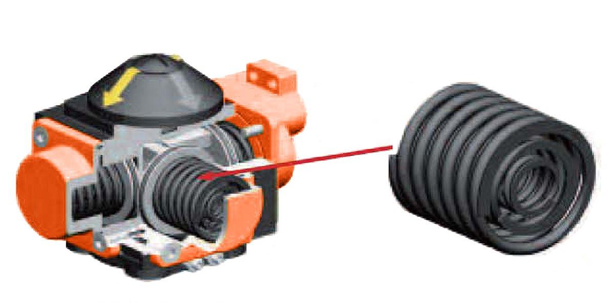
Nested springs are aligned by rings cut in the piston face and end cap. This ensures correct orientation. With four cylinder areas, many different combinations are available allowing for correct sizing.
GENERAL FEATURES
• Torqturn 4x4 utilises carbon steel pistons that allow for higher cycles because of their greater strength.
• Viton seals in the piston drive shaft also lead to higher cycles. Inside surface finish (Ra 0.4-0.6 um) to minimise friction and to maximise the life of the actuator.
• Standard applications for temperature ranges from
BUNA -4°F to176°F -20°C to BOC
Also Available:
Viton -4°F to 250°F -20°C to 120°C
EPDM -40°F to 176F -40°C to 80°C
• Piston bearing made of material with low friction coefficient to avoid metal to metal contact. Easily replaceable for maintenance.
• Double lower drilling for valve mounting, and centreing, according to ISO 5211/DIN 3337 standards.
• Independent bi-directional travel stop adjustment +/- 5° ensuring precise positioning in all flow control services, adjustable between 85° -95° rotation.
• Direct mounted solenoid connections according to NAMUR standards.
Lower female shaft key, according to ISO 5211/DIN 3337 standards, for assembly on valves with star or square shaft.
• Air supply can be dry or lubricated filtered compressed air.
• The lubrication carried out by the manufacturer qualifies for a minimum of 1,000,000 operations.
• Epoxy-coating is a deposit of powders on clean and sandblasted pieces. The chemical process is easily kept under control and after coating, the pieces must be subjected to heat treatment. Epoxy painting of actuators is advised where environment is strongly aggressive. With a normal thickness of 200/250 microns, resistance to salty fog exceeds 1,000 hours. With the exception of certain solvents, epoxy coating resists acids and alkali, and also has a good resistance to UV rays. In order to retain its properties, the coating must not be scratched.
• Visual position indicator the 4 x 4 actuators are supplied as standard.
• The indicator designed to remain on the actuator for continuous indication when limit switch is being used.**
** (Not applicable in size X40)
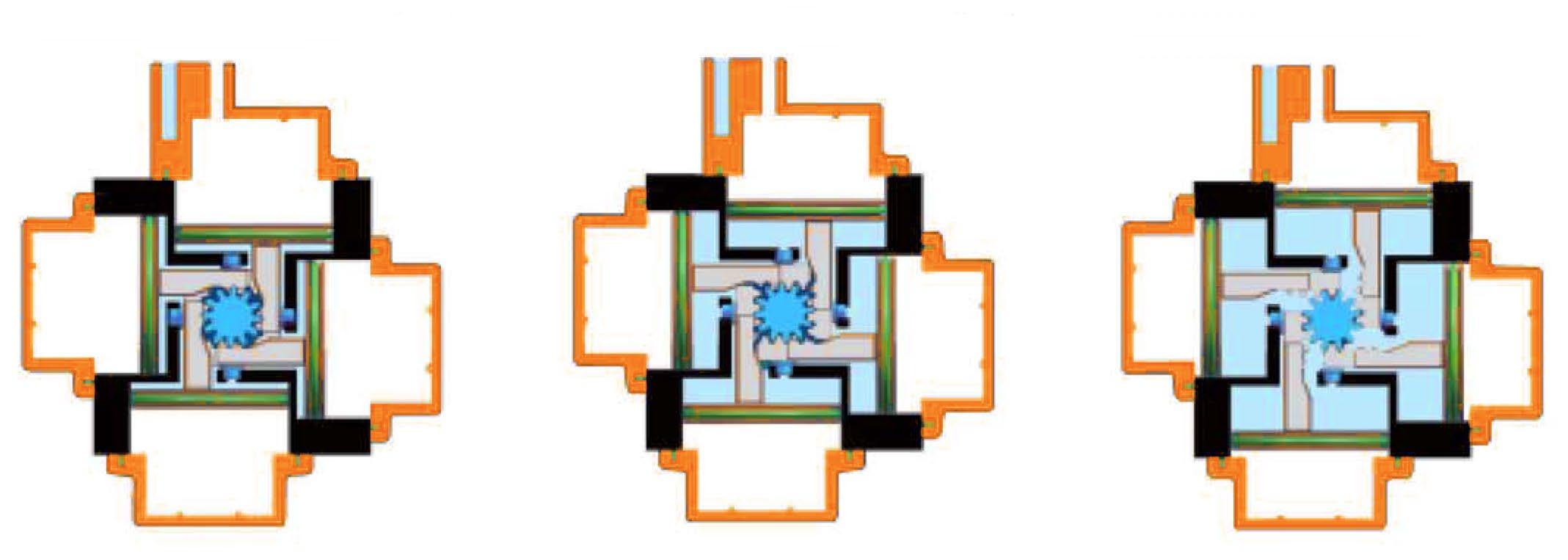
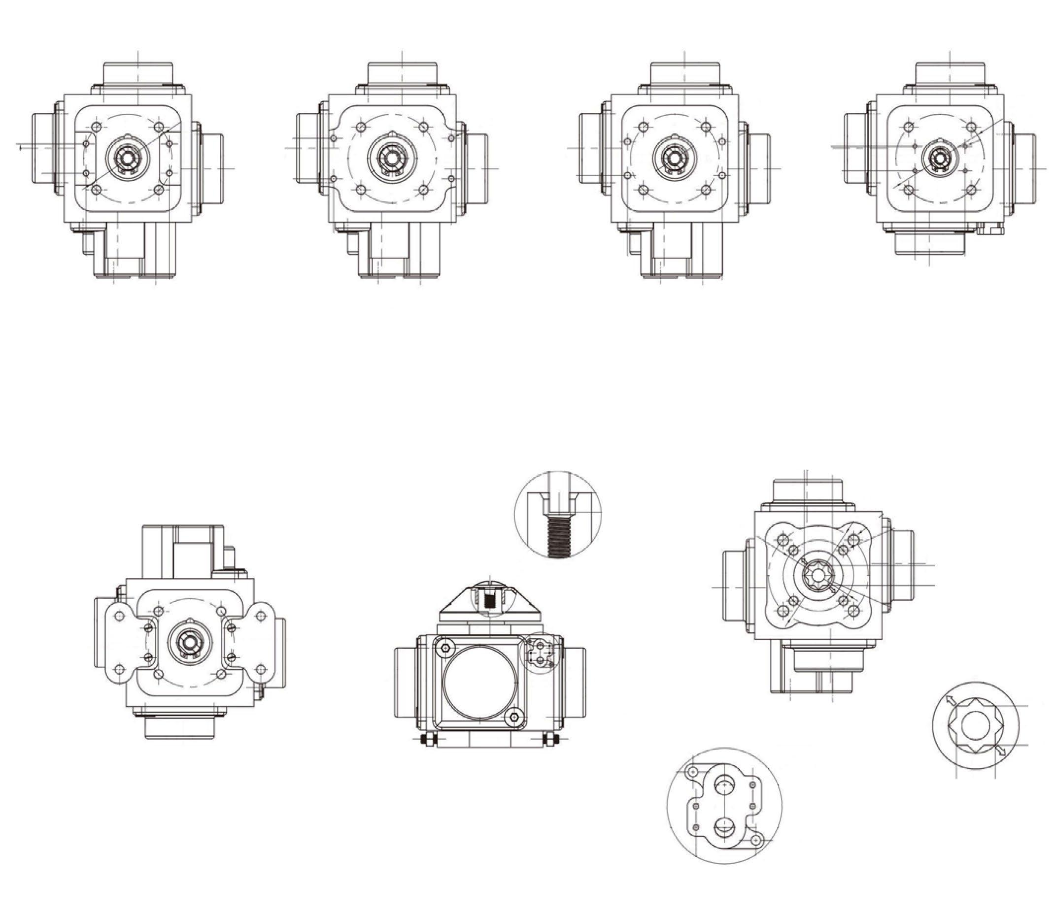
Air supplied to Port A which is connected to the center chambers forces piston apart toward end position with exhaust air exiting at Port B (a counterclockwise rotation is obtained).
Air supplied to Port B which is connected to the four chambers forces piston toward center with exhaust air exiting at Port A (a clockwise rotation is obtained).
Air supplied to Port A which is connected to the center chamber forces piston apart and toward end position compressing springs, with exhaust air exiting at Port B (a counterclockwise rotation is obtained).
Release of air allows springs to force pistons toward center position with exhaust air exiting at Port A (a clockwise rotation is obtained).
The seat material used, media, temperature, frequency of operation and critical application of the valve’s operation are all important factors in calculating the actuation needs of a given valve. The information provided below should be considered as a guide only and must be adjusted according to experience and judgement. Proper actuator selection is required to prevent valve or process equipment damage as well as proper valve operation.
For determining torque we assume that valve torque results from the friction between the ball and seats as well as the stem and stem seals.
Valve Torque
The torque requirements of the valves will vary depending on several factors.
Seat design and material
The seat friction force depends on the seat material and the applicable service factor multipliers shown in the chart below.
Stem Seal
Torque results from the stem contact with stem seals and the type of packing materials affect torque. Stem seal torque needs to be considered as a percentage of overall torque especially in small valve sizes.
Differential Pressure
Frequency of Operation
Media Influence Slurries
Temperatures
Cycle Time
Instrument Air Supply
Minimum and maximum pressures
Stuck valve torque
Dry gases, oils
Minimum and maximums
Line hammer, process requirements
Peak demand pressure availability
Media and Service Factors
To establish minimum torque requirements, multiply valve torque by the following application media and service factors.
TECHNICAL DATA
* The above indicated moving time of the actuator, are obtained in the following testcons: (1) Room Temperature. (2) Actuator Stroke 90° (3) Solenoid Valve with orifice of 4mm and flaw capacity Qn 400/L/min. (4) lnside pipe diameter 8mm, (5) Medium clean air, (8) Air supply pressure 5.5 bar (79, 75psi), (7) Actuator without external resistance load. Cautions: on the field applications when one or more of the above parameters are different, the moving time will be different.
Accessory Top Mount NAMUR Standard VDI/VDE 3845
Bottom Mount ISO 5211
G-1/4” ISO (FOR METRIC) 1/4” NPT (FOR IMPERIAL)
PORT A connected to the center chambers
PORT B connected to the outside chambers
TOP VIEW
VIEW
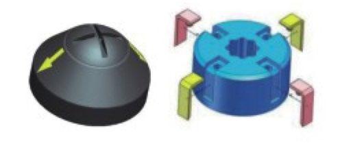
VISUAL INDICATOR
A Torqturn indicator with flow direction arrows is snapped on to the pinion, to provide easy identification of the valve position. These indicator arrows allow true positioning of any type of valve porting. These can be setup for fitting to 2 way inline ball valves or 3 way ball valves.
FEATURES
Linear pneumatic actuators for gate, globe & control valves.
3 ~ 0.8 MPa operating supply air pressure. Double acting and spring return.
MANUAL OVER-RIDES DECLUTCHABLE
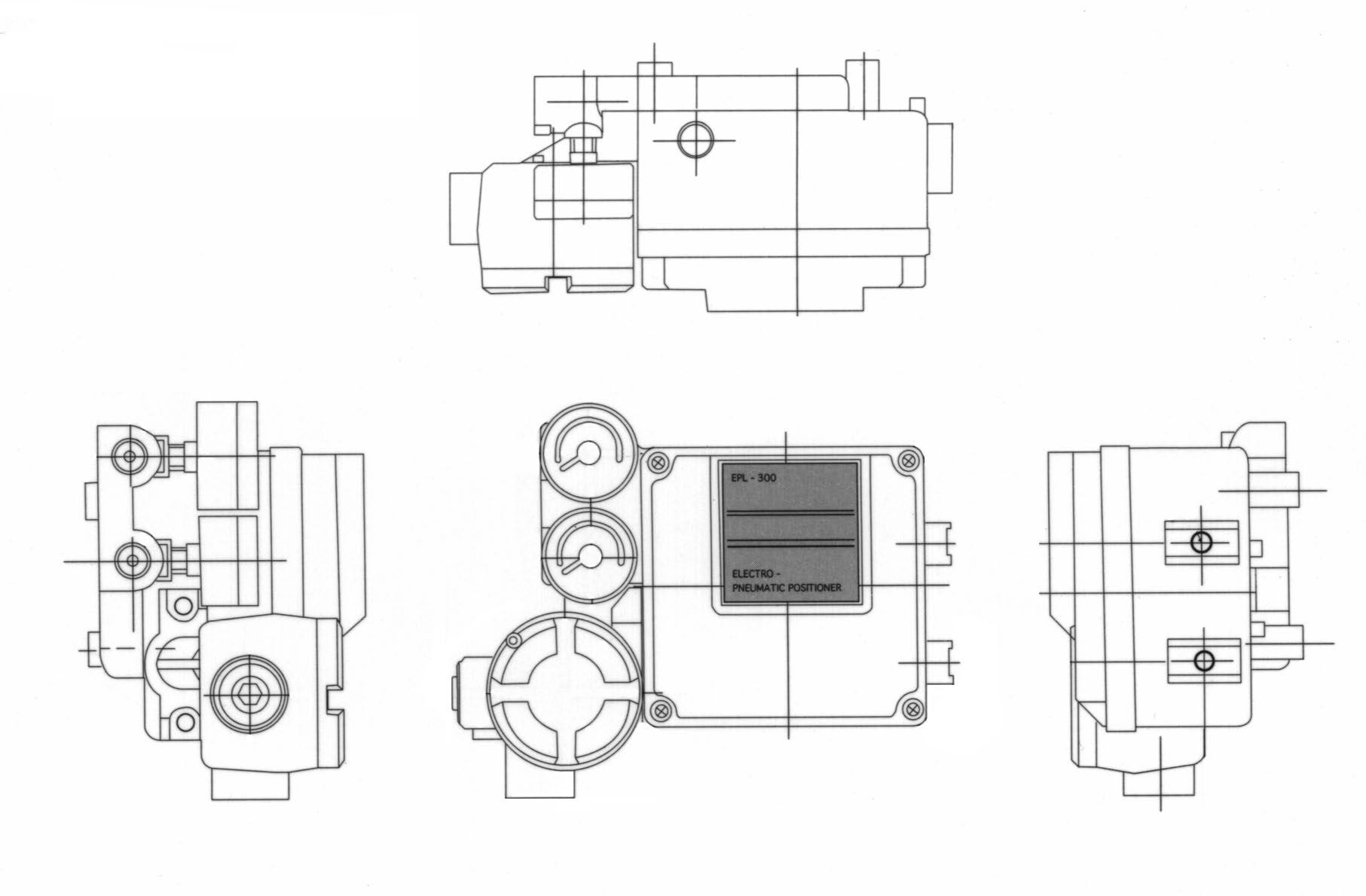
LINEAR TYPE YT1000L
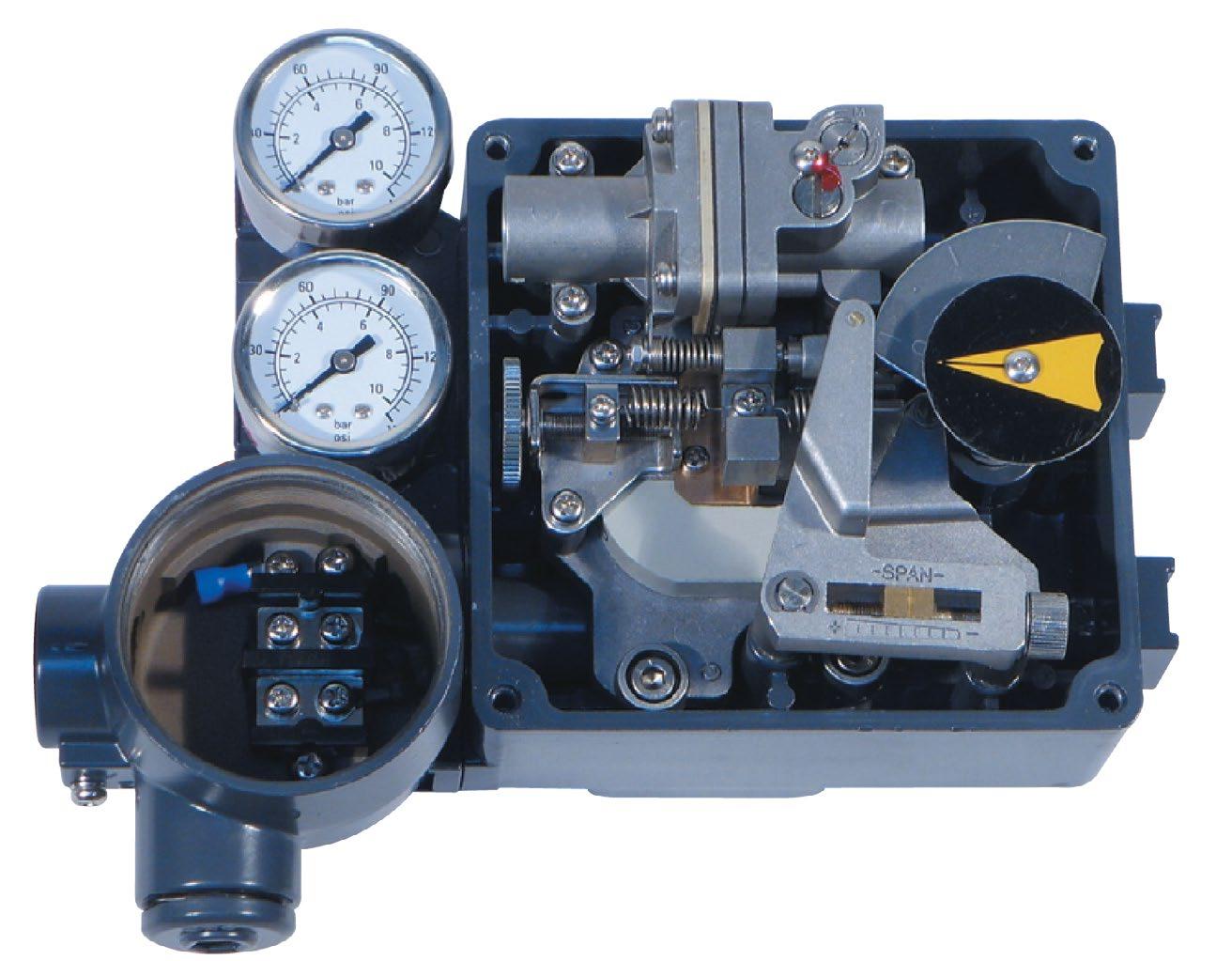
SERIES EPL - 300
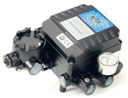
• CE Approval
• Approval for Certificate of Explosion Proof (Exia 11 BT6, Exdm 11 BT6)
• Approval for Certificate of IP66
• High resistance to vibration. (There is no resonance at 5 - 200hz)
• Designed as multi-port type for air tubing. Easy to install air tubing connection in any direction.
• Easy to convert from Direct Action to Reverse Action or vice versa.
• Performing 1/2 split control without any other substitutes.
• Designed as block build structure for maintenance and repair.
• Easy feedback connection
• Low air consumption
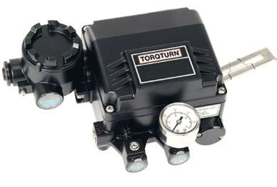
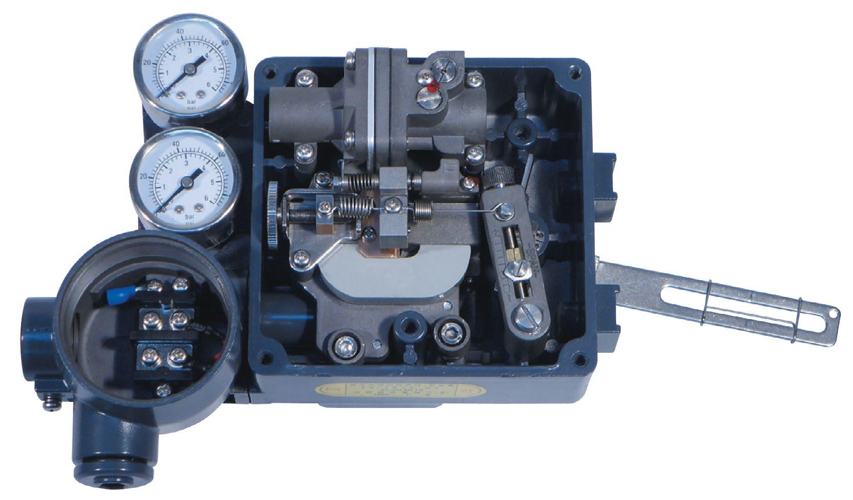
For the conversion of an electrical command signal received from a remote control device into a pneumatic control signal to position the connected final control elements (The E/P - positioner ensures a pre-selected correspondence between the valve stem position and electrical output signal supplied by the controller)
EPL(R) - 300 (E/P - POSITIONER)
Easy Maintenance
Maintenance made easy by modular construction. Each unit can be easily removed.
Excellent Anti-Vibration Structure
There is no resonance between 5 and 200hz.
Very insensitive to mechanical vibrations.
Simple zero and span adjustment 1/2” split range by simple adjustment without changing parts
Reversible operating direction
It is very easy to change a direct (DA) or reverse action (RA) direction by using the span adjusting unit.
Resistant to hostile environments
Special coating inside body and cover prevent corrosion cause by moisture.
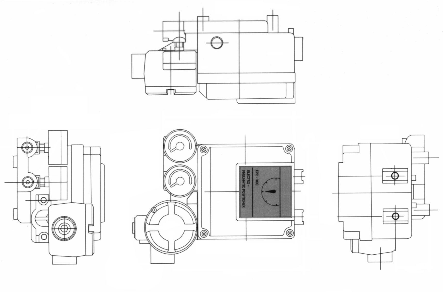
ROTARY TYPE YT1000R SERIES EPR - 300
Type Item EPL-300 (Linear) EPR-300 (Rotary)
Single Double Single Double
Input Signal 4 - 20mA DC below 24V
Impedance 250 + 150
Supply Pressure (14-7 kgf/cm2) (20-1000psig)
Stroke 10-150mm 0 - 90°
Air Connections PT (NPT) 1/4
Gauge Connections PT (NPT) 1/8
Conduits PF 1/2
Explosion Roof Exia 11 BT6, Exdm 11 BT6
Degree of Protection IP66
Ambient Temp -20°C - 70°C
Linearity ±1% ±2%
Hysteresis 1%
Sensitivity ±0.20% ±0.50%
Repeatability 0.50%
Air Consumption 3 LPM (Sup = 1 4 kgf/cm2)
Flow Capacity 80 LPM (Sup = 1 4 kgf/cm2)
Material Aluminium Diecasting
Weight 2.8 kg (Approx.)
Simple structure for feedback connection
Easy to attach small diaphragm actuators
The pneumatic and electrical ports are on the side of the body and don’t interfere with the feedback lever on the other side.
Sensitive and correct Response for high performance
Economical
Low air consumption.
Stable operation
Ease of adjustments prevents hunting.
A filtered air supply
Output and exhaust hole have a metal filter to ensure clean air supply. Compact and light weight.
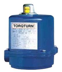
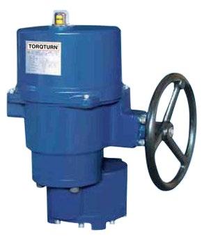
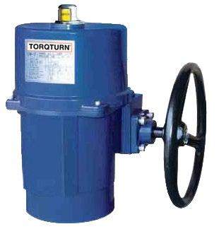
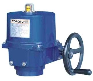
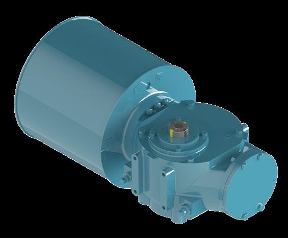
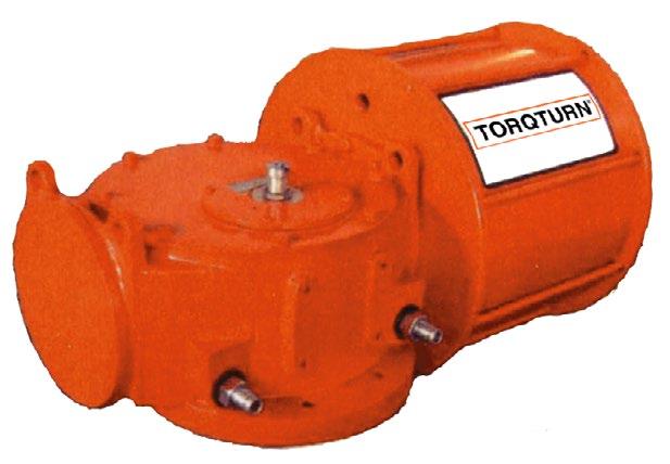
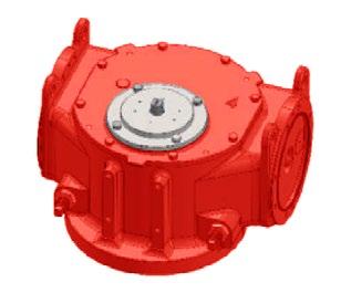
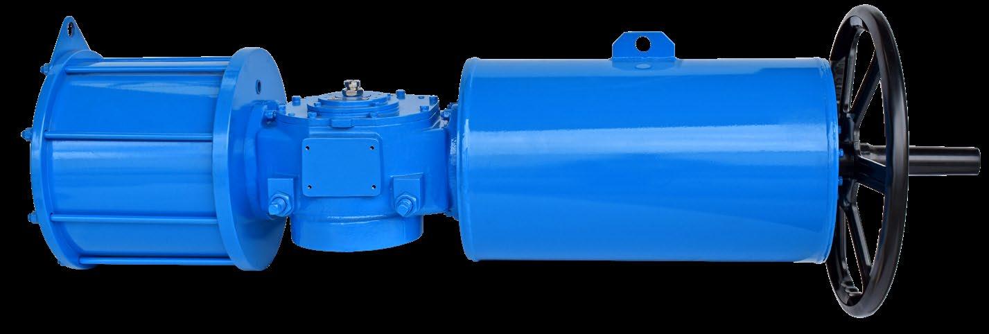
Torqturn actuators are ideal for use on butterfly, plug and ball valves with the increased benefit of self locking EPI-CYCLICAL gears, eliminating the need for unreliable solenoid brakes.
The Torqturn line of electric actuators offers a broad range of torques from 34 to 3400 Nm and numerous features including manual over-ride, auxiliary switches, 4-20ms modulating control, several voltage options including 120/60, 230/50, 3-phase 220v, 360v, and 440v. The units feature EPI-CYCLICAL gear trains and a unique manual over-ride with handwheel.
All actuators are NEMA 4x and are designed for maximum cycle life due to our rugged motors and gear trains.
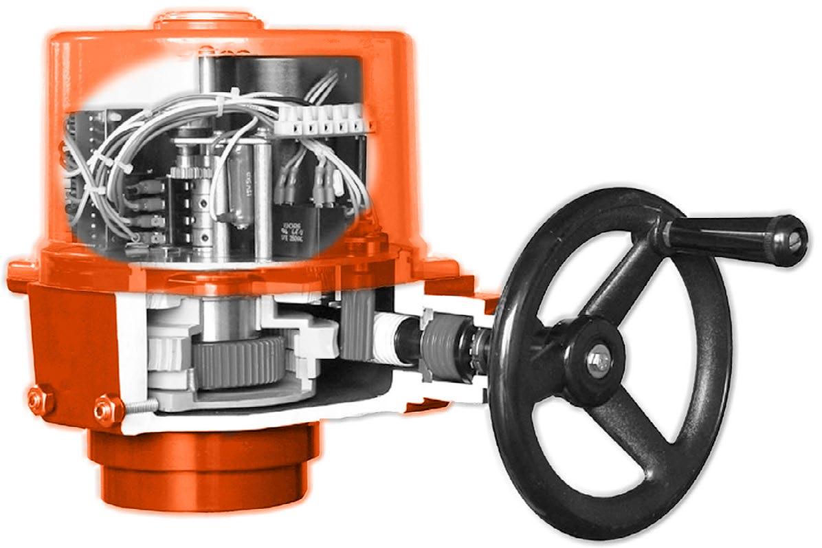
FEATURES
• Corrosion resistant NEMA 4, 4x construction.
• Die cast aluminium housing and cover, OM-1 powder polyurethane coating.
• Self-locking EPI-CYCLICAL gear train. OM-1 feature self-locking motor with spur gears.
• Standard manual over-ride with handwheel OM-2 to OM-12, OM-1 with wrench.
• Visual position indicator (ET/M-700-4300)
• CE/CSA/UL approval
• Optional 4-20ms or 0-1Dvdc modulating. All models.
• Rugged, hardened steel gears.
• Mounting kits available for ISO and other valve mounting patterns.
ELECTRIC ACTUATORS - T-STRT SERIES
PRODUCT MODEL NUMBER
1: Product Code
2: Torque
3: Blank switching mode, no additional function
PK - potentiometer output (0 - 1kΩ)
RPC - adjustable proportional controller
LP - selection of field and long range control
LM - adjustable proportional controller selection of field and long range control
4: Blank: standard
EX: anti-explosion
FEATURES
• Advanced design, high performance, light weight and high output torque.
• The inside and outside of closure is coated with epoxy resin.
• IP67 protection
• Connection to ISO 5211
• Connection shaft sleeve can easily be replaced
• Double worm wheel structure, self-locking, external adjustable mechanical position stops.
• Manual over-ride, automatic reset to electronic control after power on.
• Built-in torque switch protects against overload. Embedded thermal protector to carry out dual-protection on electrical machine.
• Valve position indication, large window for better viewing.
• Multiple filed control unit.
• Intelligent control unit option.
Refer to as built drawing.
ELECTRIC ACTUATORS - T-STRT SERIES
TECHNICAL
Protective grade
Main power supply
Control power supply
Load factor
Electrical machine
Limit switch
Torque switch
Overtemperature protection
Stroke
Valve postion indicator
IP67, O-Ring, Waterproof IP67, O-Ring seal
110/220VAC/1Ph/500/60Hz, 380/440VAC/3Ph/50/60Hz ± 10%
110/220VAC/1Ph/50/60Hz ± 10%
On-off-type
Mouse cage type electrical machine
2 open/close (SPDT 250VAC/10A Rating)
One open/close (250 VAC/10A RATING; ALE40, ALE100)(except ALE40, ALE100)
100 ± 5°C, 85 ± 10°C Built-in protector, open at 100 ± 5°C, close at 85 ± 10°C
90° ± 5° (0° - 100°)
Continuous indication of mechanical Valve position
Manual operation Clutch (except ALE40)
Self-locking
Mechanical limit
Double worm wheels self-locking (except ALE40)
One open/close, adjustable (except ALE 40)
Heater (optional) (ALE40 2W) 5W condensation-proof (ALE40 2W)
Electrical interface
Lubricating oil
Terminal strip
2-M20 x1.5 2-M20 x 1.5 thread
EP, EP-type
Spring locking type
Ambient temperature -20°C ~ +70°C Switching mode -20°C ~ +70°C -10°C +60°C Adjustable type -10°C +60°C
Ambient humidity
Quakeproof performance
External skin
90%RH Max. 90%RH (no condensation)
XYZ10g, 02-30Hz, 30min XYZ10g, 02-30Hz, 30min
Dry powder (PET)
Broad range self monitoring and diagnosis
Hall sensors are used to measure displacement, velocity and angle. The microprocessor offers a wide range of alarm and diagnosis functions which allow for easy fault localisation.
Enhanced valve and motor protection
Measuring and monitoring of both motor current and temperature provide full motor protection. Valves are moved gently in or out of the end positions at full torque.
Integrated frequency converter
The stroke of actuator can be divided into ranges: an optimal positioning speed can then be selected for different ranges to avoid water hammer and cavitation.
Electrical connection and fieldbus control
Binary and analogue are always available, even when utilising the fieldbus interface.
PROFIBUS DP and MODBUS are optional.
• Voltage supply: 3-phase AC, 380/460±10%, 50/60Hz±5%; 1-phase AC, 220±10%, 50/60Hz±5%;
• Duty mode: On-off (MOE series,) a complete stroke, S2 - 15 min; Modulating (MME series), separate strokes, S4 - 25%, Number of starts ≤1200/h
• Motor control: Variable frequency control technology
• Voltage input: 24V. DC (18-33V), max 500mA;
• Voltage output: 24V. DC (18-33V), max 40mA; short circuit protection.
• Input Signal: (1) Analogue input (optional): 4~20 mA; galvanically isolated; 250Ω inherent resistance; rising characteristic (2) Digital input (BE1~B4): 4 optocoupler, potential free; freely configurable
• Output Signal: (1) Analogue output (optional): 0/4~20 mA for position signal; load max. 500Ω; galvanical isolated; short circuit proof; rising or falling characteristic (2) Digital output: Standard 4 (BA1~4) optional 7 (BA 5~7) or 8 (BA5~8) potential free, gold coated relay contacts, galvanical isolated, freely configurable; max. 50V, overload proof; Imax. < 150 mA; Imin. > 1 mA;
• Strokes range: Minimum 1 circle for Multi-turn.
• Torque tripping: 40% ~ 100% adjustable, step 5%
• Output Speed: 40% ~ 100% adjustable, step5%
• Accuracy: (1) Multi-turn stroke ≥1 circle ≤±0.5% (2) Part-turn ≤±0.5% (3) Linear stroke ≥25mm ≤±0.5%
• Dead zone: 1% 0.5 ~ 10% adjustable
• Enclosure protection: IP67 (IP68 optional)
• Explosive protection: ExdIIBT4
• Ambient conditions: (1) Temperature: On-off duty, MOE series, -25°C to +70 °C Modulating duty, MME series, -25 °C to +60 °C Separate type, MME series, -40°C to +85 °C
(2) Humidity: ≤95%
(3) Air media: without corrosive, flammable or explosive gas
• Anticondensation: Anti condensation heater inside
• CE standard:
(1) EN 61000-6-4: 2007, EN 61000-6-2: 2005
(2) EN 61000-3-2:2006 +A1: 2009+A2: 2009, EN 61000-3-3: 2008
(3) EN 60204-1:2006+A1:2009
• Fatigue strength: 0.75g within 5 ~ 200Hz; extended strength proof with 5 ~ 150Hz, 2g sinusoidal
INTELLIGENT ELECTRIC ACTUATORS - MME/MOE SERIES
MME/MOE INTELLIGENT ELECTRIC
ABB advanced frequency converter and electronics technologies.
The gear unit provides high efficiency, maintenance free operation.
Motor in insulation class F. Measuring and monitoring of both current and temperature provide full protection.
Introduction of efficient Man-machine interface simplifies commissioning with user guidance.
Motor and control cables are connected by using screwtype terminals or PCB plug-in terminals to ensure reliable electrical contact.
Magnetic angle sensors for contact-less position detection, are operated by means of the signalling gear to detect the current valve position and torque.
A centrifugal lock prevents the hand wheel from engaging before the motor has come to a standstill.
SETUP
travel dependent
torque dependent
valve control speed
switch off mode
switch off position
end position
limit value
PARAMETER
inchmode
holdmode
remote digital control
increasing effective torque
SERVICE
4mA input calibration
20mA input calibration
4mA output calibration
20mA output calibration
delete current range
dead-zone adjustment
output polarity setting
analogue signal range
ESD target position
reset
SELF-DIAGNOSIS
error info.
alarm info.
Remote control indicator
Password protection
Failure alarm
LED light
Numerical area
Text area
Infrared port
Infrared adaptor pins
Menu indicator
Local control indicator
SYSTEM INFO.
travel time
maximum torque
software version
hardware version
actuator model phases of AC power
extended func. board
temperature
valve position
PASSWORD PROTECTION
INPUT PORTS SETTING
OUTPUT PORTS SETTING
Note: the blocks in light blue are optional, the order number are 385, 386 and 387 respectively.
BE1 ~ BE4 digital output ports can set from ‘“01” to “20” function. See table right.
Allow to open Allow to close
Analogue/ON/OFF
Basic: Four digital output ports
BA1 ~ BA8 digital output ports can set from “01” to “20” function. See table right.
385: Four digital output ports and one analogue output for valve position.
386: Field bus system, Profibus-DP or MODBUS.
387: Analogue input and output of valve position and three digital output.
Menu
Ready to run
Failure alarm
Open to end position
Closed to end position
Exceeded torque in OPEN
Exceeded torque in CLOSED
Intermediate position 1
Intermediate position 2
Remote control
Local control
Continuous signal
Pulse signal
OPEN (pulse signal)
end (continuous signal)
CLOSED (pulse signal)
end (continuous signal)
Analogue/digital control
“OPEN” indication
“CLOSED” indication
ESD indication
Manual/Automatic state
Alarm if analogue failure
A waterproof cable connector is provided in the attached zipper bag, protection class is IP67. There are several connectors available:
1 (2 for plug-in end cover)
M32 x 1.5 for cable Ø13~Ø18
M25 x 1.5 for cable Ø10~Ø16
M16 x 1.5 for cable Ø4.5~Ø8
M32 x M25 Waterproof adapter M25 x M16 Waterproof adapter 1 (none for plug-in end cover)
Note 1: Only use the same protection level cable connector with the Torqturn actuator in order to ensure slated protection level.
Note 2: All of the signal cable must be shielded.
Note 3: Cable connecting separate type actuators should not exceed more than 15 meters.
Note 4: After wiring, please use the plastic cover in attached zipper bag to screw into the unused cable hole.
Electrical wiring for digital signal input:
L1L2L3PE
380V.AC 50/60Hz 12 LNPE
220V.AC 50/60Hz
Electrical wiring for analogue signal input: The contacts default as unactivated. The contacts default as unactivated.
L1L2L3PE
.A
.A
d
In some strong vibration or super high/ low temperature fields, the Torqturn split actuator is recommended, to ensure normal operation.
We offer three terminal connections as shown above. Standard terminal connection is fast and reliable, a plug-in terminal easy to maintain, and the screw terminal for explosion-proof products
For different installation sites, Torqturns operation panel is designed to be rotatable in four directions. See the pictures above. When the actuator is side-mounted, the operation panel still faces the operator.
According to the mechanical interfaces, Torqturn electric actuators are divided into three categories:
1 Multi-turn: Actuator outputs at least 360° of angular displacement and torque. If equipped with A type output shaft it can produce a linear thrust motion.
2 Linear: Equipped with a linear thrust, the actuator can output linear displacement and thrust, and valve stem directly connected to the linear thrust rod.
3 Part-turn: Equipped with a worm gear, the actuator can output 90° of angular displacement and torque. Part-turn are divided into two categories according to their installation.
3.1 Direct mounting: A worm gearbox is connected with the flange and output shaft hole.
3.2 With base and lever: A worm gearbox is mounted on the base, and the valve is driven by lever and rod.
INTELLIGENT ELECTRIC ACTUATORS - MME/MOE SERIES
TECHNICAL DATA
MULTI-TURN ACTUATORS (MODULATING)
MULTI-TURN ACTUATORS (ON-OFF)
INTELLIGENT ELECTRIC ACTUATORS - MME/MOE SERIES
MULTI-TURN ACTUATORS (ON-OFF CONT.)
Note 1: Most actuators are self-locking.
Note 2: Switch-off torque 10% variations due to mechanical efficiency alteration, 40% to 100% adjustable.
Equipped with “A” output shaft, the actuator can drive the valve rod to produce a linear motion. All axial force is sustained by “A” output shaft. The following table is the transmission factor for stem trapezoidal thread.
VALVE TRANSMISSION FACTORS (OUTPUT TORQUE = AXIAL FORCES* FACTOR)
Note: For inside screw non-rising gate valve, factors will be multiplied by 1.5, and the sluice, factors be multiplied by 1.25, to ensure that the thrust is 3 times larger than the weight of the valve.
LINEAR ACTUATOR (MODULATING)
LINEAR ACTUATOR (ON-OFF)
Note 1: Switch-off force and speed adjustable, from 40% to 100%, at 5% step.
Note 2: Linear units are robust and an entirely encapsulated unit.
Note 3: If what is listed in the above tables do not meet your requirements, we can provide customised products.
INTELLIGENT ELECTRIC ACTUATORS - MME/MOE SERIES
PART-TURN ACTUATORS (MODULATING)
PART-TURN ACTUATORS (ON-OFF CONT.)
INTELLIGENT ELECTRIC ACTUATORS - MME/MOE SERIES
INTELLIGENT ELECTRIC ACTUATORS - MME/MOE SERIES
PART-TURN ACTUATORS (ON-OFF CONT)
Note 1: All products stroke can be adjusted within a range of 85° to 95° (mechanical limit).
Note 2: Switch-off variations of 10% due to mechanical efficiency alteration, and switch-off torque adjustable from 40% to 100%
Note 3: Speed adjustable from 40% to 100%.
Note 4: If what is listed in the above table does not meet your requirements, we can provide customised products.
“Australian Pipeline Valve produces isolation, control and flow reversal protection products for severe and critical service media in utility, steam, pipelines, oil & gas and process industries. APV valves and pipeline products form the most competitive portfolio in the market.”