“Australian Pipeline Valve produces isolation, control and flow reversal protection products for severe and critical service media in utility, steam, pipelines, oil & gas and process industries. APV valves and pipeline products form the most competitive portfolio in the market.”
APV FAMILY OF BRANDS RANGE - CATALOGUES
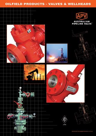
Oilfield Products Valves & Wellheads
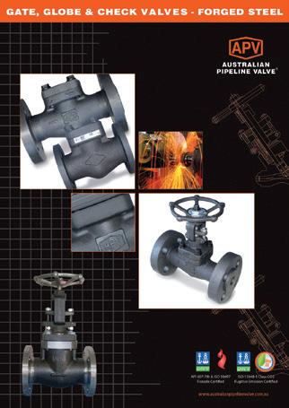
Gate, Globe & Check Valves - Forged Steel
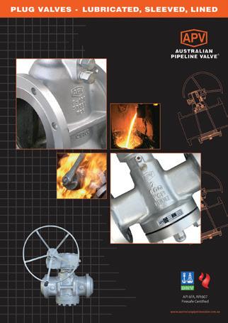
Plug Valves Lubricated, Sleeved & Lined
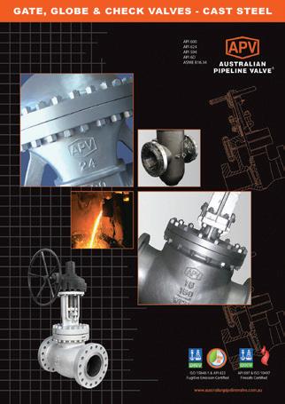
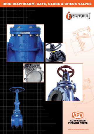
Gate, Globe & Check Valves - Cast Steel
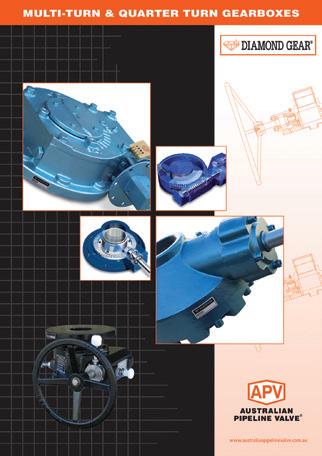
Diamond Gear Gearboxes
Flowturn Gate, Globe & Check Valves
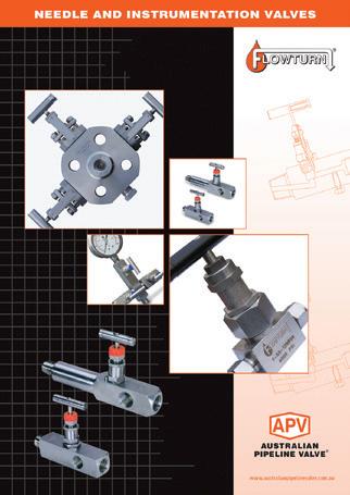
Flowturn Instrument Valves
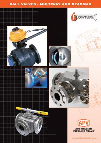
Flowturn Ball Valves Multiway & Deadman
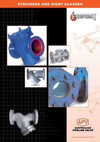
Flowturn Strainers & Sight Glasses
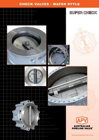
Supercheck Wafer Check Valves
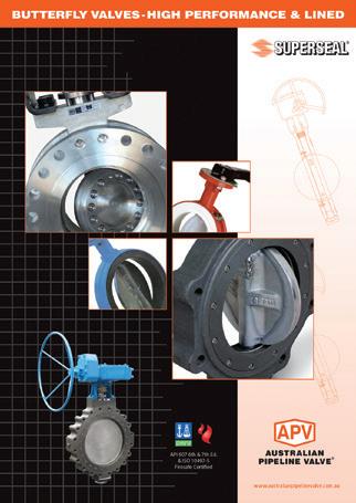
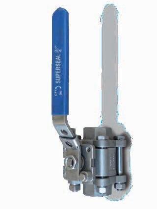
Superseal Butterfly Valves
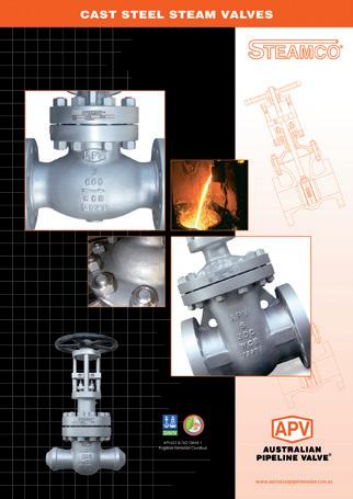
Steamco Steam Valves
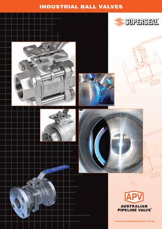
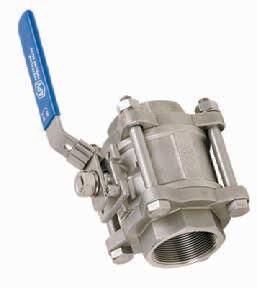
Superseal
Industrial Ball Valves
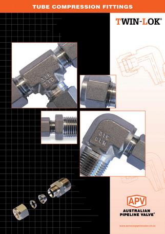
TwinLok Tube Fittings
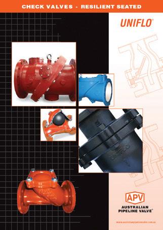
Uniflo Check Valves
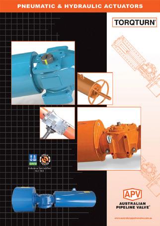
Torqturn Actuators
Ball Valves Floating & Trunnion Mounted
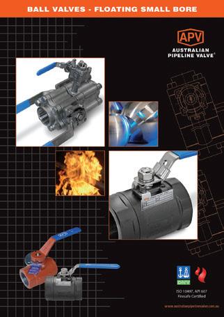
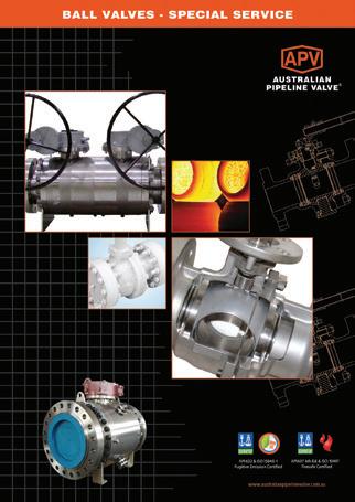
Ball Valves Floating Small Bore Ball Valves Special Service
Product Brochure
INTRODUCTION
The majority of this information is common knowledge to experienced steel valve users. When properly installed in applications for which they were designed, APV valves will give long trouble free service. This instruction is only a guide for installation, operation and minor maintenance. A professional APV approved valve engineering facility should be utilised for reconditioning and minor repairs.
Note
We do recommend however that this entire document be read prior to proceeding with any installation or repair. Australian Pipeline Valve and it’s parent company take no responsibility for damage or injury to people, property or equipment. It is the sole responsibility of the user to ensure only specially trained valve repair experts perform repairs under the supervision of a qualified supervisor.
RESPONSIBILITY FOR VALVE APPLICATION
The User is responsible for ordering the correct valves. APV Valves are to be installed in the observance of the pressure rating and design temperature. Prior to installation, the valves and nameplates should be checked for proper identification to be sure the valve is of the proper type, material and is of a suitable pressure class and temperature limit to satisfy the applications requirements.
Do not use any valve in applications where either the pressure or temperature is higher than the allowable working values. Also valves should not be used in service media if not compatible with the valve material of construction, as this will cause chemical attacks.
RECEIVING INSPECTION AND HANDLING
Valves should be inspected upon receipt to determine:
- Compliance to purchase order requirements.
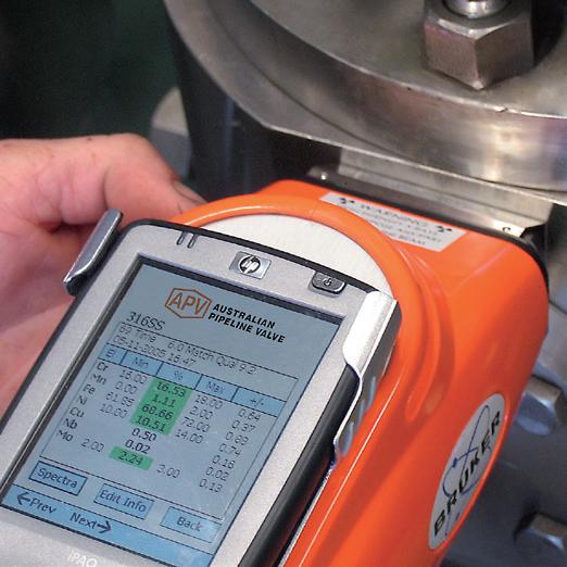
- Correct type, pressure class, size, body and trim materials and end connections (this information may be found on the nameplate or may be stamped on the body of the valve).
- Any damaged caused during shipping and handling to end connections, hand wheel or stem.
The End User is advised that misapplication of the product may result in injuries or property damage. A selection consistent with the particular performance requirements is important for proper application and is the sole responsibility of the end user.
CONSIDERATIONS OF TECHNICAL RISK/ LIMIT OF LIABILITY TO CLIENT FOR BALL VALVES
Australian Pipeline Valve don’t consider in our design the following factors of risk:
1. Australian Pipeline Valve ‘Standard’ ball valves can be used in a temperature range between -28.8 to +200°C. (Note, pressure limitations apply above 38°C refer to Pressure/Temperature charts.) For service temperatures below -28.8°C ball valve construction materials shall be submitted to an impact test at the minimum service temperature. For temperatures outside of the range of -28.8°C to +200°C ball valves have to be provided with seats, seals and body material able to withstand the temperature degree required.
2. The onus is on the customer to specify all materials of construction and service conditions. Australian Pipeline Valve shall assume standard materials and conditions if not otherwise specified.
3. Australian Pipeline Valve ‘Standard’ ball valves are not equipped with devices suitable to avoid internal over-pressures caused by incorrect operations of process or by-fluids & liquids subjected to an increase of volume and/or pressure (these devices, such as the over-pressure hole in the ball or safety seats are available upon request).
4. Australian Pipeline Valve ‘Standard’ ball valves are not designed with special devices to withstand a sudden thermal jump (thermal shock).
5. In general Australian Pipeline Valve ‘Standard’ ball valves are not mechanically designed to bear overloads due to exceptional atmospheric or natural phenomenon’s (such as earthquakes).
6. In general Australian Pipeline Valve ‘Standard’ ball valves are not designed to bear loads on flanges, on pipe connections or pipeline.
7. In general Australian Pipeline Valve ‘Standard’ ball valves can’t withstand ice inside their bodies (in this case user must specify the optional stem extension for insulating, avoiding the presence of residual product inside the valve).
8. Australian Pipeline Valve ‘Standard’ ball valves are not suitable for low temperature service below -29°C (-20°F) unless provided with cryogenic stem extension and other modifications (available on request).
9. Australian Pipeline Valve ‘Standard’ ball valves are suitable for ‘industrial’ oxygen (not medical) service when supplied degreased and packed in polyethylene bags only.
10. The compatibility between ball valves construction materials and medium is selected by the user. The user is ultimately responsible for verifying the compatibility between medium and materials.
11. Abrasive or dirty service, high temperature service, low temperature service, vacuum service, near zero pressure service and other special applications should be clearly stated when requesting quotation.
12. Floating valves without supplementary upstream relief hole in ball cannot be used for unstable fluids which, if trapped in the body cavity (valves in closed position) can be subject to the risk of increasing of pressure due to the increasing of temperature. If required, the purchaser must specify an upstream relief hole.
13. Valves without fugitive emission extensions cannot be used for toxic or dangerous medium with the risk of dispersion in the environment.
14. For fluids like oxygen, hydrogen or chlorine where the contact with oil or grease can create explosions valves that have not been properly cleaned, degreased and sealed in suitable boxes cannot be used. Avoid any kind of contamination until the moment of use. The same precautions have to be applied to valves for cryogenic services.
BALL VALVE START-UP
Before installing the ball valve onto the pipe-line it is mandatory for the user to verify the compatibility of the ball valve with service conditions (medium, temperature and pressure). With reference to standard ball valves held in stock the reseller and end user will have to assure themselves of the compatibility with the use of conditions required by the customer. Australian Pipeline Valve ball valves must be only used for on-off (fully open/fully closed) service.
Before using the ball valve in a potential explosive atmosphere it’s necessary: -
• To verify the compatibility between the ball valve and the zone in which the ball valve should be installed.
• To foresee the pipe-line ground condition on which the ball valve should be installed.
• To check that the temperature of the ball valve surface is not higher than the flammable point of the atmosphere in which the ball valve is installed (in this case specify an insulating cover device for the valve and an extension for the wrench)
• Before installing ball valves with welding ends to make sure that the process of welding is carried out in accordance with all the safety requirements of the classified zone.
• To avoid mechanical knocks during the installation that may cause sparks. Australian Pipeline Valve cannot be held responsible for damage caused by use of the product especially if it is improper use or modified.
SAFETY INFORMATION
The following general safety notices supplement the specific warnings and cautions appearing elsewhere in this manual. They are recommended precautions that must be understood and applied during operation and maintenance of the equipment covered herein.
To avoid injury, never attempt disassembly while there are pressures either upstream or downstream. Even when replacing packing rings, caution is necessary to avoid possible injury. Disassemble with caution in the event all pressures are not relieved.
To prevent valve distortion, inefficient operation, or early maintenance problems, support piping on each side of the valve.
Note
• A valve is a pressurised device containing energised fluids and should be handled with appropriate care.
• Valve surface temperature may be dangerously too hot or too cold for skin contact.
• Upon disassembly, attention should be paid to the possibility of releasing dangerous and or ignitable accumulated fluids.
• Adequate ventilation should be available for service
APV refuses any liability for damage to people, property or plant as well as loss of production and loss of income under any circumstances but especially if caused by: Incorrect installation or utilisation of the valve or if the valve installed is not fit for intended purpose. It is the sole responsibility of the client to ensure the valve type and materials are correctly specified.
SCOPE OF INSTALLATION ACCORDING TO THE TYPE OF FLUID (DANGEROUS FOR THE ENVIRONMENT OR HUMAN HEALTH)
Group 1 Classification
- The incorporation of additional safety elements “Double Packing” (utilising a stem extension) is recommended for the range of products included in Group 1.
- The use of valves without additional safety devices in Group 1 will be the responsibility of the user or the purchaser, as well as the advisability of installing leakage detection systems.
Group 2 Classification
- Carbon steel valves will not be used in corrosive fluid lines.
DURING OPERATION TAKE INTO ACCOUNT THE FOLLOWING WARNINGS:
• Graphite/Graphoil packing and body gasket is very brittle, any impacting, twisting or bending should be avoided.
• The valve’s internal parts such as ball, stem, seats, seals, gaskets shall be handled with care avoiding scratches or surface damage.
• All tools and equipment for handling internal critical sealing parts shall be soft coated.
• Valves can be fitted with gaskets or seals in PTFE, Buna, Viton, etc., hence high temperatures will damage sealing components.
• Never part open valve. Valve must be full open of full closed to avoid seal damage.
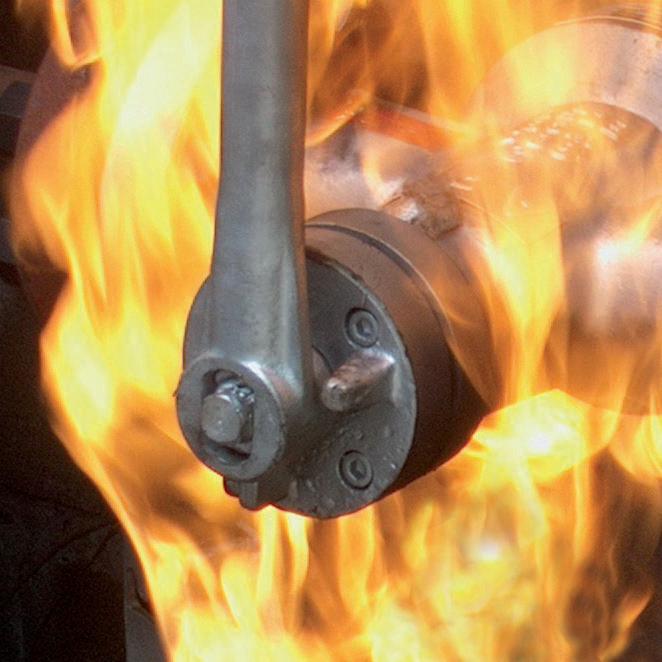
• APV firesafe ball valves are provided with anti-static devices for ball-stem-body. When service conditions require electrical continuity to prevent static discharge, the user is responsible for specifying static grounding.
• When ball valves are to be utilised on liquids with very high velocity, check with the valve distributor or manufacturer for appropriate advice to minimise the possibility of seat deformation, especially when they are highly pressurised on a high-temperature line.
• Ball valves are generally not recommended for throttling service, where both the fluid flow and the leading edge of the ball can damage or deform the resilient ball seats causing leakage. High fluid velocity or the presence of solid particles in suspension will further reduce seat life in throttling applications.
• Do not open the bonnet or cap when bearing pressure. Valve is not equipped with pressure access device. User should check it by other method through its piping system.
• Do not touch the surface of a valve at high temperature.
• Not allowed for unstable fluid unless otherwise specified.
• Lock design on the handle is to avoid the valve being operated by non-related people and is an option upon request.
For all operations make reference to position number on part list of the applicable drawing listed.
a- The internal parts of valves (ball, stem, seat) shall be handled with care avoiding scratches or surface damage.
b- All tools and equipment for handling and supporting the internal parts shall be coated with soft materials.
c- Seat & seals can include Viton, EPDM, Buna & Teflon hence high temperatures will damage sealing components.
d- Never part open valve, or part close, valve must be fully open of fully closed else seats will be damaged. Ball valves are not suitable for throttling.
1.0 GENERAL PRECAUTIONS
a. Material Selection:
The possibility of material deterioration in service require the need for periodic inspections. Carbide phase conversion to graphite, oxidation of ferrite materials, decrease in ductility of carbon steels at low temperature (even in applications above -29°C) can also cause serious degradation of valve and danger to safety. Even information about corrosion data is available; the user is requested to take attention or consideration to determine the suitability of material in their application.
b. Pressure-Temperature Rating:
The pressure temperature rating is considered for static pressure. Please refer to P & T ratings in as-built drawing, see Section 4.0 for example. Do not exceed the temperature range to avoid dangerous accidents.
c. Fluid Thermal Expansion:
It is possible, when the ball valve is in closed position, the sealed cavity within the valve body to be filled with liquid. If this liquid is not released, by partially opening the valve or some other means, and it is subject to a temperature increase, excessive pressure sufficient to cause pressure boundary failure can be generated. However, our products have pressure self-relief seats to prevent pressure build up. User is recommended to ensure the valve will not exceed the allowed pressure, by means of piping design, installation, or operation procedure.
d. Static Electricity Effect:
The ball valves are provided with anti-static devices for ball-stem-body. When service conditions require electrical continuity to prevent static discharge, the user is responsible for specifying static grounding.
e. Liquids With High Fluid Velocity:
When ball valves must be operated frequently on liquids with very high velocity, a check shall be made with the valve distributor or manufacturer for appropriate advice to minimise the possibility of seat deformation, especially when they are highly pressurised on a high -temperature line.
f. Throttling Service:
Ball valves are generally not recommended for throttling service, where both the fluid flow and the leading edge of the ball can damage or deform the resilient ball seats causing leakage. High fluid velocity or the presence of solid particles in suspension will further reduce seat life in throttling applications.
g. Do not open the bonnet or cap when the valve is in the line or still contains fluid/gas. Ball valves are not equipped with pressure access device.
h. Do not touch the surface of the valve at high or low temperature.
i. Superseal VT-3 Series are not firesafe and not allowed for flammable or unstable fluid or gases.
j. Lock design on the handle to avoid the valve operated by non-related people is an option as requested by the user.
2.0 PRODUCT DESCRIPTION
2.1
FEATURES
- Blowout proof stem
- Anti-static devices for ball-stem-body
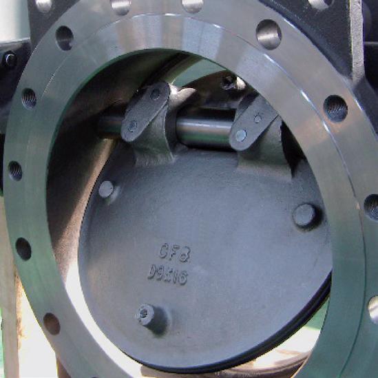
- Heavy duty body & end cap construction with traceable heat number
- Pressure balance hole in ball slot
- Pressure self-relief seat to prevent pressure build up
- Lock design on the handle is optional requirement
3.0 PRESSURE TEMPERATURE RATINGS
The pressure-temperature rating of ball valves are determined, not only by valve shell materials, but also by sealing materials used for ball seats, stem packing and body seal. Sealing materials may be high molecule, elasticity and hardness, however, the choice is limited by the characteristics of the service fluid, temperature, pressure, velocity of fluid, frequency of valves operation and sizes of ball valves etc, The general rating chart below is for non-shock fluid service for floating ball valves distinguished by sizes and seating materials.
Chart shown in Figure 1 is example only. Refer to as-built drawing or APV-Superseal catalogue for pressure/temperature chart.
4.0 DELIVERY CONDITION & STORAGE
Valves stay in the open position during the transportation. For incoming QC, they must check:
a. Packing condition: Is there any damage during the transportation.
b. The bolts of cap and yoke: to make sure the bolt does not loose tightness when it arrived.
Valves must be stored in an indoor warehouse to avoid dust and other foreign objects, not exposed in an open space without a cover over. Remove the packing under any unnecessary situations.
5.0 INSTALLATION & OPERATION
5.1 HANDLING
During ball valve installation, the procedure must be followed to handle at both sides of the body. If using cable for a larger sized valve, make certain the cable is strong enough to ensure safety during the installation.
5.2 CLEANING
Operator must check to see if there any foreign bodies or dust inside the bore. If there is, clean it before installation. The operator can clean the valves using water, compression air or steam (automation valve shall be cleaned only with water or steam, the compression air is not allowed.) For cleaning operation, first step is to put the valve bore perpendicular to the ground and clean, ensure all the dust can be removed from the bore. The second step is to check and clean all the connecting pipe connections.
5.3 VALVE INSTALLATION (INSTALL IN THE PIPELINE SYSTEM)
5.3.1 Direction
VT-3 valves are bi-directional.
5.3.2 Position
VT-3 valves can be installed in any orientation however, the stem should be in upright position more than a 90 degree tilt to avoid ingress of debris into the stem area. Do not bear any weight from pipeline on the valve.
5.3.3
Tightening
To tighten the bolts of the flange end caps, the force must distributed on every single bolt evenly. The order to tighten the bolts needs to be completed symmetrically generally and evenly ensuring bolts on opposite sides are gradually tightened. See Table 1 below for maximum torque.
Body Bolt Tightening Sequence
1
FIGURE 2
5.3.4 Hydrostatic test
Before delivery, valves are tested 1.5 times the allowable pressure at ambient temperature in the open position. For seat test refer to as-built drawing and material certificate. After installation, the piping system may be subject to system tests, not to exceed the above mentioned pressure.
The size of the actuator and setting of the input power or pressure of the actuator are depended on the operation torque. User is recommended to refer to the instruction from the actuator supplier. Overload torque applied by the actuator may transfer the un-intended load to the ball valve itself or to the piping joints. Setting of the input power or pressure of the actuator is not to exceed published maximum stem torque, refer to as-built drawing. As a guide, consult APV if torque of actuator is over 1.5 times the Break To Open (BTO) of the valve.
5.4 VALVE INSTALLATION BY WELDING
For all sizes of valves, leave valves in the full open position during installation, welding and post-weld heat treatment. This will reduce temperature transmission to soft seats. After welding completion, open the valve and flush line to clean out any foreign matter.
5.4.1
Method
The welding temperature will adversely affect the PTFE and elastomer components. It will be the responsibility of the operator to ensure valves are kept cool during welding and then post-weld testing of the valve should be performed to ensure no distortion or buckling of end caps. The ‘swing out’ centre should be disassembled prior to welding to avoid damage to seats and body seals (only 3 bolts need to be removed to ‘swing out’ the centre section of the remaining bolt). The seats remain in the centre section hence no seat removal is required. If this option is recommended by APV then these valves have in-line removable sections hence no line movement is necessary to insert the fully self contained section. There must be sufficient movement in line to allow tightening of body bolts to compress the body gasket.
1- Tack weld in 4 points on both caps, leave the valve in the open position and do not move during and at least 30 minutes after welding until the valve cools.
2- Remove centre section and complete welding.
3- Replace centre section but first apply grease to the seat rings to aid the seat and torque (unless for oxygen service).
The below procedures should also be followed:
a) Always ensure there is no pressure or product in the line. Ball valves will be supplied with socket weld ends to ANSI B16.11 or butt weld ends to ANSI B16.25. Welding should be done using procedures and welders qualified under section IX of the ASME boiler and pressure vessel code.
b) Always do as low temperature weld as necessary to obtain a reliable connection. Use whatever measure necessary to localise heat at the joint, dissipating it before damage can occur to adaptor gaskets and/or seats (the main risk is seats). Use a tempil stick or other temperature indicator on the outside of the valve body (centre section) directly adjacent to adaptor end piece) being welded to.
5.5 OPERATION
a. For manual operation, shift the handle in the counter clockwise direction for close and clockwise for opening.
b. If the handle is in a parallel position with the flow direction, the valve is open. If the handle is at a right angle position with the flow direction, the valve is closed.
c. When installing the actuator or the valve is operated with a removable handle, the user should ensure the position of the valve whether open or close. The below diagram shows how to access the position of ball valve.
Floating valves without supplementary upstream relief hole in ball cannot be used for unstable fluids which, if trapped in the body cavity (valves in closed position) can be subject to the risk of increasing of pressure due to the increasing of temperature. If required, the purchaser must specify an upstream relief hole.
Valves without fugitive emission extensions cannot be used for toxic or dangerous medium with the risk of dispersion in the environment. For fluids like oxygen, hydrogen or chlorine where the contact with oil or grease can create explosions valves that have not been properly cleaned, degreased and sealed in suitable boxes cannot be used. Avoid any kind of contamination until the moment of use. The same precautions have to be applied to valves for cryogenic services.
6.0 OPERATION IN SERVICE
1. After installation into the pipeline, it is necessary to check the function of the product by operating the valve at least 3 times.
2. The whole pipeline system may be tested with proper pressure. User shall take care that the testing pressure shall not exceed 1.5 times the allowed working pressure.
3. After pressure testing, user shall operate the valve at least 3 more times to ensure proper function.
7.0 DANGERS OF INAPPROPRIATE USE
Never use the product in excess of it’s allowed condition, such as pressure, temperature and fluid.
If the product is inappropriately used, the valve may be damaged however, signs may not occur immediately. User shall change the valve to avoid danger in the future.
8.0 MAINTENANCE
Valves should be periodically checked at least once every 3 months, but depending on service, criticality and frequency of use, more regular checking may be required.
Packing leakage could result in personal injury. Valve packing is tightened prior to shipping but may require adjustment to meet specific service conditions. If a valve does not fully close, damage to the seat and body will result due to the venturi effect resulting in high pressure erosion. Flush or remove the valve at next opportunity.
A good program of inspection and maintenance cannot be over stressed. It is recommended that the valve be periodically and at least partially stroked/function tested to ensure the valve functions and prevent seizure/sticking of any mating surfaces. Duration depends on service, criticality etc. However it also must be factored in that if there are impurities or particulates in the line each operation could reduce seat life proportionately. Periodic inspection of critical leak-path areas such as body/bonnet joint, end connections, seating surfaces, and around the stem packing should be a requirement. The most common area for leakage is around the stem packing, this is usually due to wear and can normally be stopped by adjusting the packing.
Do not attempt to replacing packing or replace stem while the valve is in service! (The stem is blowout proof and can only be removed by disassembling the valve).
8.1 MAINTENANCE FREQUENCY
The maintenance frequency is determined upon the application of the ball valve. User shall consider the time interval dependant on the kind of fluid velocity, operation frequency, high-pressure effect and high-temperature effect etc.
8.2
GLAND PACKING
In case of slight leakage from the gland, gland packing nut should be lightly tightened up without effecting torque.
8.2.1
Stem Leakage – Stem Packing Replacement
The most common point for leakage is around the stem and packing this leakage can normally be stopped by adjustment of the packing gland. If this does not stop the valve leakage, the valve will have to be repacked.
The system and valve MUST be depressurised and removed from the line before attempting any repair work. After removing all pressure from the valve and draining the system the following procedure should be used to repack the valve.
1. Remove nuts or screw from the lever. Remove the lever and lock plate. Remove the gland nuts.
2. Remove old packing, taking care not to scratch or damage the stem of stuffing box. Note, the stem design is anti-blow out so the stem cannot be removed up through the top of the valve.
3. Clean and inspect stem, stuffing box, and gland. If any scratches, nicks, or corrosion is found, the parts should be replaced.
4. Slide each packing ring over the stem and into packing chamber. Carefully tap each ring into place and continue installing rings until the recommended number of rings have been installed. A thin smear of molybdenum sulfide anti-seize grease may be used on the stem and packing chamber wall for packing lubrication.
5. Replace and tighten gland nut(s) alternately in 1/4 turn increments until a reasonable torque is applied to lightly compress packing. Lubricate stem and cycle valve through a couple of complete cycles.
6. If slight stem leakage occurs after system is pressurised, continue tightening gland nut in alternating 1/4 turn increments until leakage stops. Once leakage stops, continue tightening gland plate nuts and additional 1/4 turn. There is also a PTFE seal ring/bearing and larger sizes/higher classes also have an elastomer o-ring. However, these parts can only be replaced during complete disassembly of the valve. Should replacement of packing fail to prevent the leakage, complete reconditioning of the valve may be required. See table 2 below for maximum torque. Do not attempt to tighten further. Torque shown is a maximum only. Tighten only as required.
Personal injury may result from sudden release of any process pressure. APV recommends the use of protective clothing, gloves and eye wear when performing any installation or maintenance. Isolate the valve from the system and relieve pressure prior to performing maintenance. Disconnect any operating lines providing air pressure, control signals or electrical power to actuators.
8.3 DISASSEMBLY
1. The user should check the availability of the VT-3 service kit before disassembling the valve. The user should order the original service kit from APV.
2. To dismantle the valve the user must follow the procedure and drawings and use caution as mentioned in this IOM.
3. Be very careful when removing the valve from the pipeline as it may contain hazardous fluid. The ball must be opened slightly to let the fluid out slowly. The operator must also be weary of any poisonous and hazardous media.
4. The operator must turn the ball to the close position before dismantling the valve. The ball cannot be taken out from valve body if the ball is in the open or semi-open position.
5. To dismantle the valve body, release the end caps carefully.
8.4 PARTS INSPECTION, MAINTENANCE & REPLACEMENT
1. Check the surface of ball & stem for damage. Operator may perform a PT for inspection if necessary. Replace the ball and stem if damaged.
2. The operator needs to gauge if the damage is located on the contacting area of ball and ball seat. If it is the case, then the ball must be replaced otherwise the ball will damage the soft seat during the open and close operation or it will dig out the ball seat and cause heavy damage to ball and seat.
3. Inspect the surface of soft seats for any scrape marks, scratches etc. Replace the seats if any imperfections on seat face, sides or back of seat.
4. The stem packing may be replaced after dismantling the valve. Refer to 9.2 for tightening packing gland.
5. Hydrostatic test body and seat as per ISO 5208/API 598. 1.5 Times working pressure body. The seat should be pneumatic tested 5.5 Bar (80 psi) air and optionally hydrostatic tested at 1.1 times working pressure.
5. Final inspection of the valve includes operating the valve at least 10 times, open and close to ensure all the parts are assembled correctly. The torque must have the same value during the open/close operation. If the torque is not the same during operation, then there may be some parts incorrectly positioned or causing interference. The valve must be dismantled and re-assembled to correct the problem. Otherwise, the valve is easily damaged when working on a pipeline under higher pressure.
8.5 ASSEMBLY
The assembly process is the opposite way shown dismantle process in 9.3. The valve must be in the close position whilst assembling the body and end cap, the stopper must be located in the right place; otherwise, the open and close operation will be opposite.
APPENDIX
Sample Drawing VT-3-L300 8~80NB Direct Mount
Example only, refer to as-built drawing
DIMENSIONS (MM) & WEIGHT (KG)
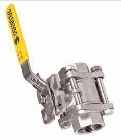
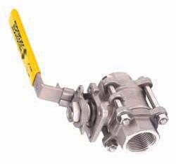
Floating Ball Valve, 3PC, High Cycle Design, Direct Mount Pad,Model VT-3-L300 NPS 1/4”~3” (DN8~DN80), 6890 KPA (1000 PSI), Lever Operated, FB, CF8M
APPENDIX - CONT’D.
Sample Drawing VT-3-L300 100NB Direct Mount
Example only, refer to as-built drawing
Floating Ball Valve, 3PC, High Cycle Design, Direct Mount Pad,Model
APPENDIX - CONT’D.
Sample Drawing VT-3-M300
Example only, refer to as-built drawing
Floating Ball Valve, 3PC, High Cycle Design, Mount Pad, Model VT-3-M300 NPS 1/4”~3” (DN8~DN80), 6890 KPA (1000 PSI), Lever Operated, FB,
Floating Ball Valve, 3PC, Model HVT-3-L NPS 1/4”~2” (DN8~DN50), 13780 KPA (2000 PSI), Lever Operated, FB, CF8M
APPENDIX - CONT’D.
Sample Drawing HVT-3-L 80NB
Example only, refer to as-built drawing
Floating Ball Valve, 3PC, Model HVT-3-L NPS 3” (DN80), 10330 KPA (1500 PSI), Lever Operated, FB, CF8M
APPENDIX - CONT’D.
Sample Drawing HVT-3-W BUTTWELD
Example only, refer to as-built drawing
Floating Ball Valve, 3PC, Model HVT-3-W NPS 1/4”~2” (DN8~DN50), 13780 KPA (2000 PSI), Buttweld S40, Lever Operated, FB, CF8M
WARRANTY
1. LIMITED WARRANTY: Subject to the limitations expressed herein, Seller warrants that products manufactured by Seller shall be free from defects in design, material and workmanship under normal use for a period of one (1) year from installation but in no case shall the warranty period extend longer than eighteen months from the date of sale. This warranty is void for any damage caused by misuse, abuse, neglect, acts of God, or improper installation. For the purpose of this section, “Normal Use” means in strict accordance with the installation, operation and maintenance manual. The warranty for all other products is provided by the original equipment manufacturer.
2. REMEDIES: Seller shall repair or replace, at its option, any non-conforming or otherwise defective product, upon receipt of notice from Buyer during the Manufacturer’s warranty period at no additional charge. SELLER HEREBY DISCLAIMS ALL OTHER EXPRESSED OR IMPLIED WARRANTIES, INCLUDING, WITHOUT LIMITATION, ALL IMPLIED WARRANTIES OF MERCHANTABILITY AND FITNESS OR FITNESS FOR A PARTICULAR PURPOSE.
3. LIMITATION OF LIABILITY: UNDER NO CIRCUMSTANCES SHALL EITHER PARTY BE LIABLE TO THE OTHER FOR INCIDENTAL, PUNITIVE, SPECIAL OR CONSEQUENTIAL DAMAGES OF ANY KIND. BUYER HEREBY ACKNOWLEDGES AND AGREES THAT UNDER NO CIRCUMSTANCES, AND IN NO EVENT, SHALL SELLER’S LIABILITY, IF ANY, EXCEED THE NET SALES PRICE OF THE DEFECTIVE PRODUCT(S) PURCHASED DURING THE PREVIOUS CONTRACT YEAR.
4. LABOR ALLOWANCE: Seller makes NO ADDITIONAL ALLOWANCE FOR THE LABOR OR EXPENSE OF REPAIRING OR REPLACING DEFECTIVE PRODUCTS OR WORKMANSHIP OR DAMAGE RESULTING FROM THE SAME.
5. RECOMMENDATIONS BY SELLER: Seller may assist Buyer in selection decisions by providing information regarding products that it manufacturers and those manufactured by others. However, Buyer acknowledges that Buyer ultimately chooses the product’s suitability for its particular use, as normally signified by the signature of Buyer’s technical representative. Any recommendations made by Seller concerning the use, design, application or operation of the products shall not be construed as representations or warranties, expressed or implied. Failure by Seller to make recommendations or give advice to Buyer shall not impose any liability upon Seller.
6. EXCUSED PERFORMANCE: Seller will make a good faith effort to complete delivery of the products as indicated by Seller in writing, but Seller assumes no responsibility or liability and will accept no back-charge for loss or damage due to delay or inability to deliver, caused by acts of God, war, labor difficulties, accidents, inability to obtain materials, delays of carriers, contractors or suppliers or any other causes of any kind whatever beyond the control of Seller. Under no circumstances shall Seller be liable for any special, consequential, incidental, or indirect damages, losses, or expense (whether or not based on negligence) arising directly or indirectly from delays or failure to give notice of delay.