Superseal High Performance Double Offset Butterfly Valve IOM
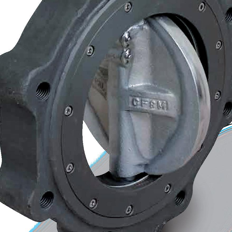
HIGH PERFORMANCE BUTTERFLY VALVES “DOUBLE OFFSET” MODEL SLHBF & SLHBFFS
COMPLETE PRODUCT LINE
“Australian Pipeline Valve produces isolation, control and flow reversal protection products for severe and critical service media in utility, steam, pipelines, oil & gas and process industries. APV valves and pipeline products form the most competitive portfolio in the market.”
APV FAMILY OF BRANDS RANGE - CATALOGUES
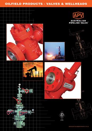
Oilfield Products Valves & Wellheads
Gate, Globe & Check Valves - Forged Steel
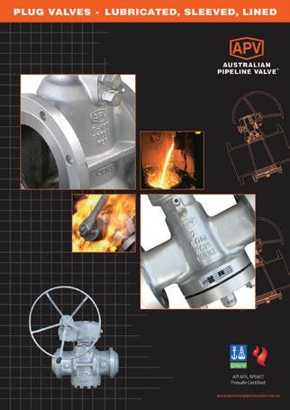
Plug Valves Lubricated, Sleeved & Lined
Gate, Globe & Check Valves - Cast Steel
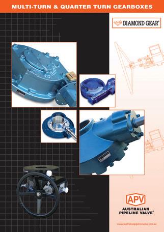
Diamond Gear Gearboxes
Flowturn Gate, Globe & Check Valves
Flowturn Instrument Valves
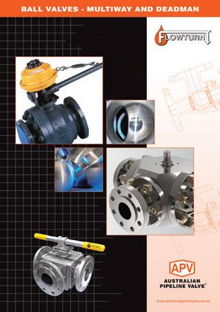
Flowturn Ball Valves Multiway & Deadman
Flowturn Strainers & Sight Glasses
Supercheck Wafer Check Valves
Superseal Butterfly Valves
Steamco Steam Valves
Superseal
Industrial Ball Valves
TwinLok Tube Fittings
Uniflo Check Valves
Torqturn Actuators
Ball Valves Floating & Trunnion Mounted
Ball Valves Floating Small Bore Ball Valves Special Service
Product Brochure
INTRODUCTION
The majority of this information is common knowledge to experienced steel valve users. When properly installed in applications for which they were designed, APV valves will give long trouble free service. This instruction is only a guide for installation, operation and minor maintenance. A professional APV approved valve engineering facility should be utilised for reconditioning and major repairs.
Note
We do recommend however that this entire document be read prior to proceeding with any installation or repair. Australian Pipeline Valve and it’s parent company take no responsibility for damage or injury to people, property or equipment. It is the sole responsibility of the user to ensure only specially trained valve repair experts perform repairs under the supervision of a qualified supervisor.
RESPONSIBILITY FOR VALVE APPLICATION
The User is responsible for ordering the correct valves. APV Valves are to be installed in the observance of the pressure rating and design temperature. Prior to installation, the valves and nameplates should be checked for proper identification to be sure the valve is of the proper type, material and is of a suitable pressure class and temperature limit to satisfy the applications requirements.
Do not use any valve in applications where either the pressure or temperature is higher than the allowable working values. Also valves should not be used in service media if not compatible with the valve material of construction, as this will cause chemical attacks.
RECEIVING INSPECTION AND HANDLING
Valves should be inspected upon receipt to determine:
- Compliance to purchase order requirements.
- Correct type, pressure class, size, body and trim materials and end connections (this information may be found on the nameplate or may be stamped on the body of the valve).
- Any damaged caused during shipping and handling to end connections, hand wheel or stem.
The End User is advised that misapplication of the product may result in injuries or property damage. A selection consistent with the particular performance requirements is important for proper application and is the sole responsibility of the end user.
SAFETY INFORMATION
The following general safety notices supplement the specific warnings and cautions appearing elsewhere in this manual. They are recommended precautions that must be understood and applied during operation and maintenance of the equipment covered herein.
To avoid injury, never attempt disassembly while there are pressures either upstream or downstream. Even when replacing packing rings, caution is necessary to avoid possible injury. Disassemble with caution in the event all pressures are not relieved.
To prevent valve distortion, inefficient operation, or early maintenance problems, support piping on each side of the valve.
• A valve is a pressurised device containing energised fluids and should be handled with appropriate care.
• Valve surface temperature may be dangerously too hot or too cold for skin contact.
• Upon disassembly, attention should be paid to the possibility of releasing dangerous and or ignitable accumulated fluids.
• Adequate ventilation should be available for service
This manual describes the methods of installation and maintenance for lined butterfly valves. APV refuses any liability for damage to people, property or plant as well as loss of production and loss of income under any circumstances but especially if caused by: Incorrect installation or utilisation of the valve or if the valve installed is not fit for intended purpose. It is the sole responsibility of the client to ensure the valve type and materials are correctly specified.
DURING OPERATION BEAR IN MIND THE FOLLOWING WARNINGS:
a- The graphoil packing and body gasket is very brittle: any twisting or bending shall be avoided.
b- The internal parts of valves (disc, stem, seat) shall be handled with care avoiding scratches or surface damage.
c- All tools and equipment for handling and supporting the internal parts shall be coated with soft materials.
d- Seats & seals usually include Viton, Buna & Teflon hence high temperatures will damage sealing components.
e- Never part open or part close valve, valve must be fully open of fully closed or else seats will be damaged.
f- Check to see if the valve is specified for isolation service only or for control valve use or both (typically metal seated valves are suitable for control valve use). Also, familiarise yourself with the shut off class of the valve as various levels of shut off classes can be specified.
For all operations make reference to position number on part list of the applicable drawing and overview diagrams 4 to 9. Overview explosions shown in diagrams 4 to 9 are general drawings only, for more accuracy refer to the as-built drawings supplied with the order.
1.0 OVERVIEW
1.1 GENERAL NOTE
High performance butterfly valves have a Double eccentricity and can be used for automatic proportion control or isolation. However, for control valve use, valves must be metal to metal seated and throttling over 75% closed or under 25% open will still dramatically reduce seat & disc and valve body life, even more so at higher pressures and if service is not clean. Also for throttling/control applications, a special metal to metal seat design must be specified which is typically class IV or V shut off. However, normally the triple eccentric SLHBFFS-T is specified for control valve use or class VI shut off isolation service is required. A simple and unique valve design enables the user to assemble and disassemble easily.
Only model SLHBFFS is firesafe not SLHBF. SLHBFFS must have graphite stem packing or it is not firesafe. Even in metal to metal seat design if only class IV shut off then the valve is not firesafe design. The valve is only firesafe if API 607 is indicated on the lable and the material certificate. For fugitive emission service special packing systems must be specified.
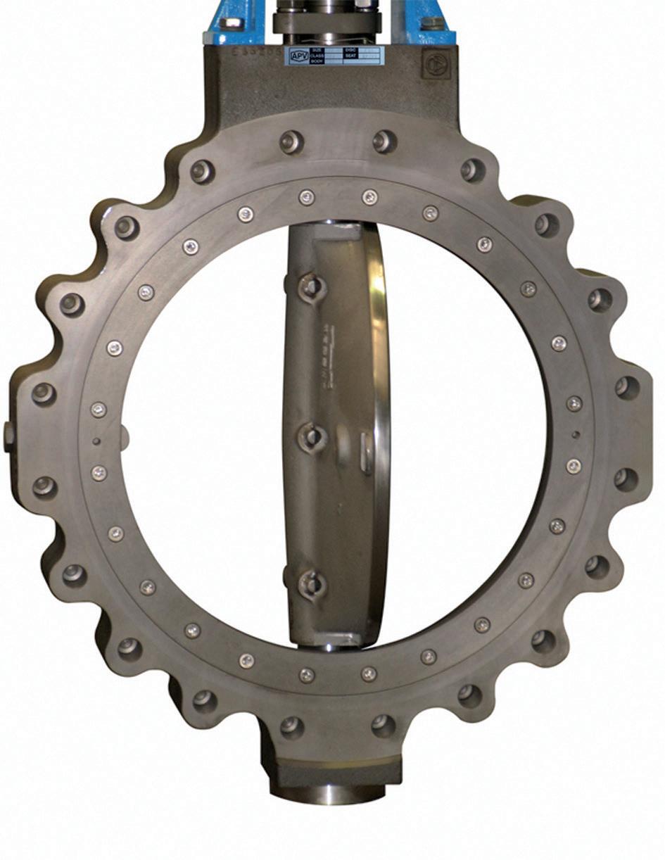
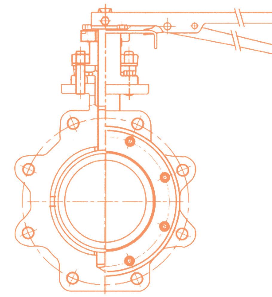
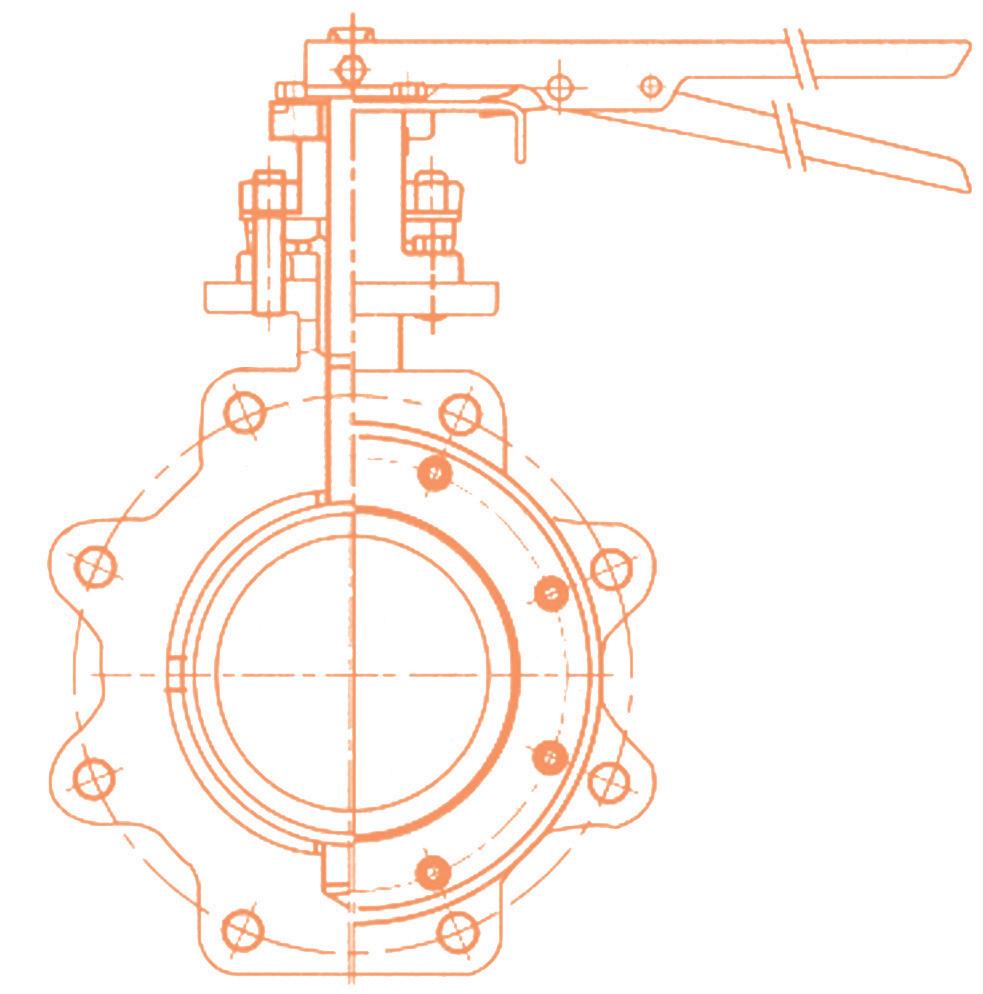
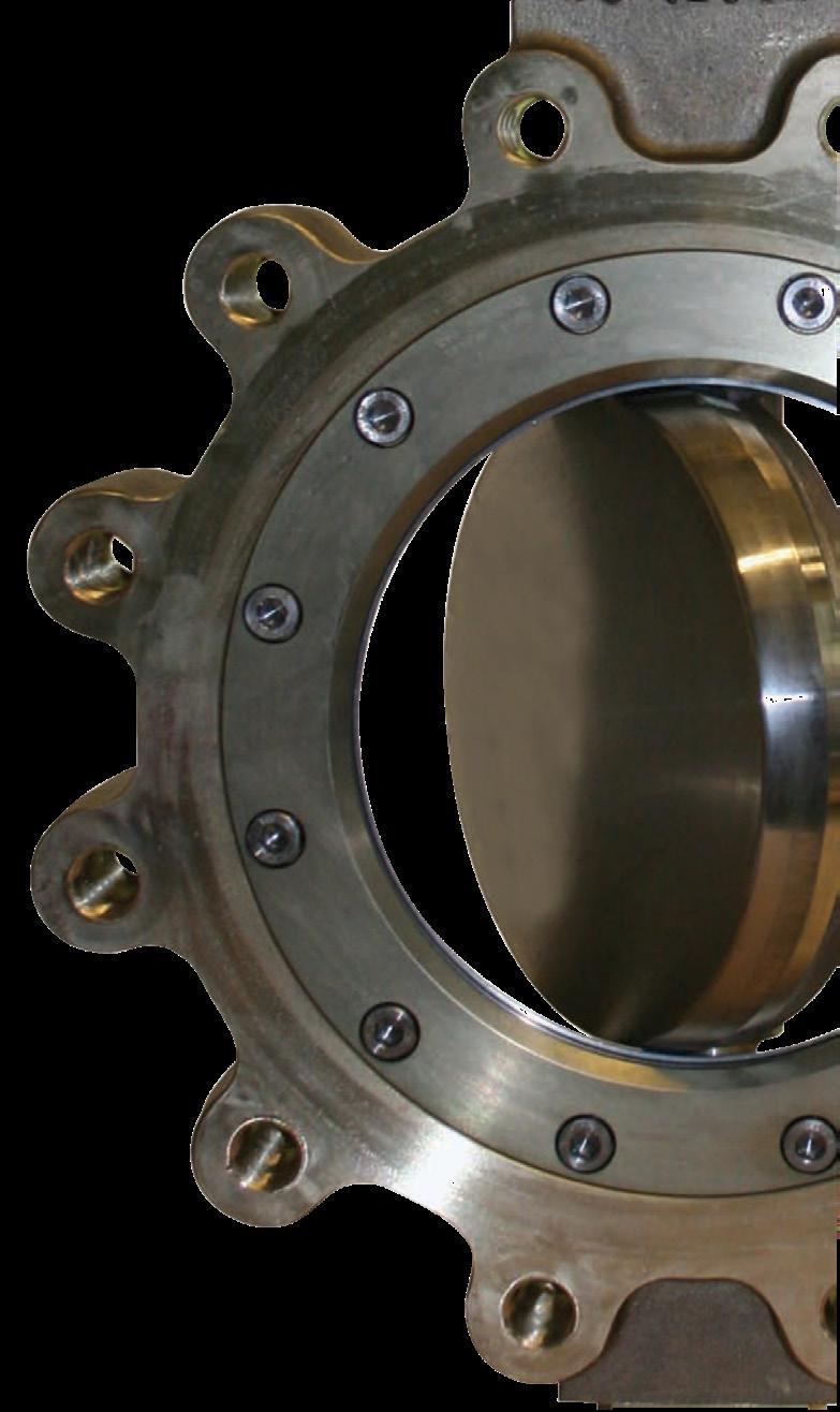
1.2 TYPE
Valves are classified as Wafer Type, Lugged Type or Flanged. Their principal parts consist of body, disc, seat and stem. Material of each part is determined by the application and working condition of the valve.
1.3 SCOPE
This manual describes the methods of installation and maintenance for high performance butterfly valves.
2.0 STORAGE
2.1 TEMPORARY STORAGE
If valves are to be stored before installation, the following should be observed:
a) Keep the valves wrapped and protected as shipped from the manufacturer.
b) Do not remove the protective ends covering until the valve is ready for installation. This will reduce the possibility of foreign material damaging the internal valve components.
c) Valves stored outdoors should be positioned such that water does not accumulate in the valve body.
d) We recommend you tropicalise bore and ends of valves if stored in humid or salt air environment.
2.2 LONG TERM STORAGE
If valves are to be stored more than one year, they should be prepared in the following manner:
a) Remove the packing and apply a preservative to the packing chamber.
b) Do not remove the protective end covering.
c) Do not store the valves outdoors.
2.3 PREPARATION
If storage in the field for a long time before installation is necessary, it is suggested to put valves in a dry and/or covered place. In this case the packaging and end covers integrity is especially important. All the valves are supplied with special plastic ends to cover and protect the internal parts. We recommend you do not remove them during storage period. Valves should be left in open position (unless actuated and set fail closed).
a) Remove the valve end protection.
b) The inside of the valve should be inspected and blown out with compressed air. Adjacent piping must be clean and free from debris to prevent damage to the valve.
c) To prevent valve distortion, inefficient operation or early maintenance problems, support piping on each side of the valve.
d) Make sure the valve is positioned such that there is sufficient space so that the handwheel is easily and safely reached and there is enough clearance for the stem when the valve is open.
e) Install valve according to the flow indicator on the valve body where applicable.
3.0 OPERATION
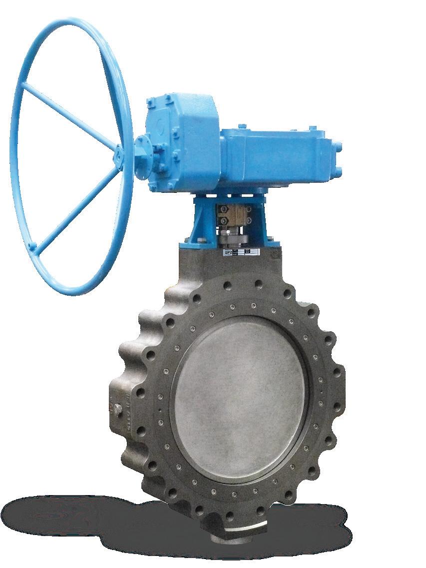
The valve operator types include: lever handle, manual gear, pneumatic actuator and electric motor operated actuator. By rotating or closing the valve’s disc flow can be controlled through the pipeline by regulating the flow or shutting it off. (Generally, on-off direction is indicated on the operator). For control valve use, valves must be ‘metal to metal’ seated and throttling too far closed or at a small percentage of open will dramatically reduce seat & disc and valve body life, even more so at higher pressures and if service is not clean.
3.1 MANUAL OPERATION
Valve adjustment is performed by clockwise turning of the stem. Lever operated and gear operated valves have a position indicator to indicate open or closed (see Diagram 2). Normal isolation butterfly valves are not designed to be used for throttling. Do not leave part open, or seats will be damaged. Valves must be full open or full closed. (See 3.0 above for control valve applications).
DIAGRAM 2
3.2 LOCK DEVICE
Where provided (optional) the valve has a locking lug that allows valve to be locked in full open or full closed position.
4.0 PRE-INSTALLATION
Before installation of the valve to the line, it is recommended to inspect the valves as below.
4.1
INSPECTING VALVE & ACCESSORIES
- Ensure that there has been no damage to the valve during transportation.
- Remove the protective end covers just before installation and clean internals and face with an air gun or with a clean dust cloth.
- Check the tightness of all the bolts and nuts.
4.2
INSPECTING PIPELINE
- Remove foreign materials such as a rust, welding slag, etc., which remain in the pipeline.
- Ensure flanges and gasket surface are clean.
When the fluid is flowing through the line, any foreign materials can damage the disc, seat and inner body causing leakage past the seat.
4.3 PRESSURE TESTING OF PIPE SECTION
- First thoroughly flush newly installed line systems in order to flood out all foreign substances.
- The testing pressure of an opened valve must not exceed the value of 1.5 x PS (at 20°C/68°F). The component with the lowest PN limits the maximum permissible testing pressure in the line section. (PS = maximum permissible operating pressure, see also name plate).
- A closed valve must only be pressure-tested with 1.1 x PS.
4.4 INSTALLATION IN PIPELINE
The sealing surfaces on flange ends are designed according to EN 1514-1 or ANSI B16.21. Mating must feature smooth sealing strips, e.g. shape C, D or E in accordance with the EN 1092 or EN 1759 standard. For a flange connection only suitable gaskets must be used.
To avoid any damage to valves with weld ends: When welding the valve into the pipeline the welding process has to be controlled in such a way that the supplied heat is limited and a distortion of the valve body is avoided.
The actuator is adjusted for the operating data stated in the order: The setting of the end stops “OPEN” and “CLOSED” must not be altered without the consent of APV.
If - in exceptional case - a valve has to be mounted without an actuator, it has to be ensured that such a valve is not pressurised.
No valve must be operated the permissible pressure/temperature range (=”rating”) of which is insufficient for the operating condition.
The non compliance of this instruction involves a risk to life and limb and may cause damage to the pipe system.
- Butterfly valves with a short face-to-face dimension: - mating flanges and/or pipe ends have to feature a clear span allowing for sufficient space for the opened valve disc so that the latter is not damaged when being swivelled out. Refer to dimensions on APV drawing.
– Prior to installation the valve and the down-stream pipeline have to be thoroughly cleaned of any contamination, especially of hard foreign substances.
Valves with a short face-to-face dimension have to be mounted with disc in closed position otherwise the valve disc could be damaged.
4.5 SAFETY PRECAUTIONS
- Ensure the line is depressurised and drained.
- Check the pipeline media. Care should be taken for protection against toxic and/or flammable fluids.
- Never install the valve without an operator already attached to the valve shaft.
- Never remove the operator from the valve while the valve is in the pipeline under pressure.
- Always ensure that the disc is in the full-closed position before installing the valve.
- Take care handling the valve.
5.0 INSTALLATION
- Make sure the valve disc is fully closed. (Usually, valve is delivered with disc closed tightly to protect the seat ring).
– Check the preferred flow direction indicated by the arrow on the valve body.
- Be sure to place a gasket between the valve and pipe flange.
- Refer Appendix A for bolt tightening sequence example. Gradually tighten more each rotation.
- See Diagram 3.
- Before installing the valve, the user must check the valve model, connection dimension and flowing direction of the medium, ensure in accordance with requirement of valve. Confirm the construction material list on nameplates (service, pressure, temperature) are appropriate for the application intended and are as specified.
- Inspect the seat ring to make sure that it was not damaged during lifting & handling process. This is especially important in case of valves shipped with the disc in the open position and with ‘fail-open’ actuators.
- Define the preferred mounting orientation with respect to the system pressure. If any (see the arrow on body), identify the upstream side (high pressure) and downstream side (low pressure).
- Optimum valve installation is with the stem in a horizontal plane (with the actuator on top of the valve not below it as any packing leaks could damaged the actuator/gearbox) or worse case have the stem at an angle so as to minimise solid particles present in fluid that otherwise could deposit in the low bearing area.
- Check the packing gland to ensure it is properly tightened.
- During installation, the disc must be in closed position.
- For working temperature above 200°C thermal insulation of valve body is recommended.
- The installer must have skilled and experience in valve installation and maintenance.
The valve will operate in both directions, however, the valve must be installed so flow is in the direction indicated on the body as the valve is designed to isolate flow from one direction. If you require bidirectional isolation it must be specified when ordering, even a preferred flow direction may still be indicated.
Over torque on the bolts might cause damage of gasket.
For preferred flow direction refer to valve and drawing
Piping should be properly aligned and supported to reduce mechanical loading on the end connections.
5.1 INSTALLATION POSITIONS
Butterfly valves should be installed as indicated in Diagram 3.
5.2
PREPARATION FOR INSTALLATION
• Remove protective end caps or plugs and inspect valve ends for damage to threads or flange faces.
• Thoroughly clean adjacent piping system to remove any foreign material that could cause damage to
DIAGRAM 3
Flange gaskets should be centered along with valve.
prevent leakage through gasket, tighten the bolts completely.
seating surfaces during valve operation.
• Verify that the space available for installation is adequate to allow the valve to be installed and to be operated.
Ensure sufficient clearance for the stem in the full open position. Inadequate clearance for valves may add mechanical loading to the valve ends.
Note
6.0
MAINTENANCE
No maintenance is required unless the valve leaks. However, routine inspection is recommended for safety and a longer lifetime. Maintenance should only be performed by an experienced valve maintenance specialist & with knowledge of high performance butterfly valves. Normal maintenance for a Superseal HPBV is limited to adjustment of the shaft packing by tightening down evenly on the gland flange using the gland flange studs and nuts. Over tightening of the gland should be avoided since this will shorten the life of the packing. During commissioning, it is common for dirt and foreign objects to be left in the pipeline during construction. This debris can damage the HPBV seat or disc edge which will prevent the valve from providing tight shut-off. In such cases seat replacement may be necessary.
- Inspect the body, disc and packing after the valve has been in service for a long period of time.
- Check the valve if any abnormal sounds or resistance is noticed during operation.
- Regularly ensure the tightness of each body bolt.
It is recommended that the valve be periodically at least partially stroked to ensure the valve functions and will prevent seizure/galvanisation of any mating surfaces in stem chamber or seat area (or in the case of resilient seats) memory moulding of the seat. Duration depends on service, criticality, etc. However, it also must be factored in that if there are impurities or particulates in the line each operation could reduce seat life proportionately.
Information in this IOM is only a general guide to serve as an example. The design is different depending on size, class, seat option, trim type, body style, service & client specification. Refer the as-built drawing for actual parts.
6.1 PACKING
Leakage from the packing area of the valve can be prevented by tightening of the gland flange’s nuts and bolts. If the leakage doesn’t stop, packing replacement may be required instead. In this case, see 6.5 for the method of packing replacement.
The packing cannot be replaced when the valve is in-line!
6.2 SEAT RING/SEAT RETAINER
Before installation in the line, check the condition of the seat ring and the bolting tightness of the seat retainer.
Gland Flange
Packing Gland Packing
All repair work (disassembly and replacement etc.) of our valve should be performed by well-trained maintenance personnel. Only an APV approved service centre should attempt major repairs. Our repair centre can arrange reconditioning if required.
6.3 REMOVING VALVE FROM THE LINE
To repair a leaking valve, the valve must be removed from the pipeline and the parts dismantled as below by experienced, qualified personnel:
- Shut down the line and ensure that there is no pressure in the pipeline.
- Drain all product from the pipe.
- Completely close the disc of the valve.
- Remove the valve from the pipe.
DIAGRAM 4
Packing leakage could result in personal injury. Valve packing is tightened prior to shipping but may require adjustment to meet specific service conditions. If the fluid is hazardous or toxic then proper protection is required before the removal of the valve.
Always be sure that the valve is de-pressurised and isolated prior to performing any maintenance work. Do not attempt to repair valve in-line if volatile, dangerous, hazardous or flammable service.
Personal injury may result from sudden release of any process pressure. APV recommends the use of protective clothing, gloves and eye wear when performing any installation or maintenance.
Isolate the valve from the system and relieve pressure prior to performing maintenance.
Disconnect any operating lines providing air pressure, control signals or electrical power to actuators.
6.4 DISMANTLE THE SEAT RING & SEAT RETAINER
Reconditioning or internal repairs to the valve should only be undergone by an APV approved repairer. This is only a general guide to serve as an example. The design is different depending on size, class, seat option, service, etc. Refer the as-built drawing.
- Open the disc of valve (10~15 degree) with operating device.
- Remove the tightened retainer bolts on the seat retainer plate.
- Remove the seat retainer by lifting up with the jacking tap.
- Take out the inner seat. Be careful not to scratch or damage the seat ring. Clean the retainer plate and seat as well as the other parts of the valve with a soft dust cloth or air blaster.
- Refer to Diagram 6 below for disassembly of the seat retainer & seat ring. There are numerous seat ring designs & configurations, refer to 6.4.1 seating styles. This is only a generic indicative guide.
- Refer Table A below for retainer bolt torques. The lip-seal seal seat design in non firesafe configuration up to 125 NB utilises an embedded clamp ring seat retainer in lieu of bolted insert. Refer to as-built drawing.
DIAGRAM 6
Retainer Bolts
Seat Retainer
Seat Ring
Retainer Bolts
Turn the Disc 10~15 degree to open.
Table A
6.4.1 Seating Styles METAL TO METAL SEAT (FLEXIBLE FLO-SEAL STYLE) (SOLID ENERGISED STYLE)
FIRESAFE SOFT SEAT (ENERGISED FLO-SEAL STYLE)
FIRESAFE SOFT SEAT (ENERGISED LIP-SEAL STYLE)
SOFT SEAT (ENERGISED FLO-SEAL STYLE) NON FIRESAFE
SOFT SEAT (ENERGISED LIP-SEAL STYLE) NON FIRESAFE
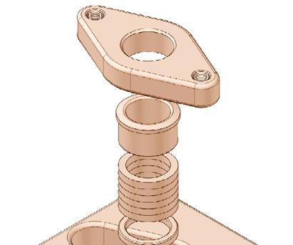
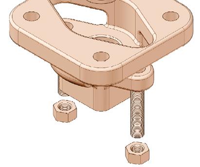
6.5 PACKING REPLACEMENT
For replacement of packing, please take the following steps:
a. Remove the Gland Flange after loosening the nuts of the gland flange.
b. Slightly lift the packing gland up and remove it.
c. Remove the packing using a packing extractor such as a screw or awl and gimlet.
d. When you remove the packing with tools (packing extractor), be careful not to scratch and damage the packing housing wall or the valve stem because such damage may cause leakage.
e. Insert a new set of packing in the packing housing after carefully cleaning the packing housing.
f. After inserting the packing, assemble the packing gland and gland flange.
g. The nuts of gland flange should be tightened sufficiently. Be careful not to over tighten the nuts as this may increase operating torque.
Diagram 7, 7A & 7B are indicative. Refer to as-built drawing.
DIAGRAM 7
DIAGRAM 7A
DIAGRAM 7B
Check the packing box for pressurised process fluids even after the valve has been removed from the pipeline, particularly when removing packing hardware or packing rings, or removing packing box pipe plug.
If a gasket seal is disturbed while removing a adjusting gasketed parts, APV recommends installing a new gasket while reassembling. A proper seal is required to ensure optimum operation.
Note Over tightening of the bolts may cause thread damage.
6.6 END COVER REPLACEMENT
For replacement of packing, take the following steps:
a. Remove the bolts and end cover.
b. Remove the gasket.
c. After removing the gasket, clean the neck of the body prior to replacement of new gasket.
d. Insert the new gasket.
e. Put the end cover on & tighten the end cover bolts.
Diagram 8 & 8A are indicative. Refer to as-built drawing.
DIAGRAM 8
DIAGRAM 8A
Bottom Bonnet Flange (where applicable)
Bonnet Parts (where applicable)
6.7 SEAT RING REPLACEMENT
If fluid can’t be shut-off under the full closing position of disc, then seat damage is suspected. In the case of seat damage, replacement should be carried out as follows:
a. Refer to 6.4 for instructions on disassembly of seat ring/seat retainer.
b. Replace the damaged seat ring with a new one.
c. New seat ring should be seated to matching angle of the disc profile (i.e. usually 10~15° of disc opening angle).
d. For re-assembling of the seat retainer, reverse the steps of the previous disassembly.
e. Slightly tighten the seat retainer bolts up to the closing position.
f. Rotate the disc a couple of times and then tighten the bolt completely with the 10~15° of disc-opening angle.
g. Finally, rotate the disc several times to ensure the correct position of the seat. The above needs to be done to get the seat settled in position.
h. Install the valve on the pipeline with disc fully closed.
Note
Over tightening of bolts may cause damage to bolts or valve. Studs should be lubricated prior to installation. Bolt tensions shown in table 1 must be decreased by 25% when no lubrication used. Non lubricated bolts can have an efficiency of up to 50% less than the torque of values stated.
INDICATIVE* TORQUE VALUES FOR TIGHTENING FLANGE BOLTS Ft Lb (Nm)
1 1/2 - 8 UN 1200 (1627) 1500 (2034) 1200 (1627)
1 5/8 - 8 UN 1600 (2170) 2000 (2712)
(1) Torques shown are for A193 B7/B7M/B16/B8/B8M and A320 L7/L7M/B8/B8M.
(2) Torque tolerance ±10%.
1 3/4 - 8 UN 2000 (2712) 2500 (3390)
(3) For temperatures above 750°F (400°C) use 75% of the torque values.
(4) Above torque values are with the bolts lubricated.
1 7/8 - 8 UN 2500 (3390) 3100 (4204)
2 - 8 UN 3000 (4068) 3800 (5153)
1501 (2035)
1907 (2585)
2357 (3195)
2876 (3898)
(5) Values above are based on 30,000 psi (206.85 Mpa) bolting stress and lubricated with heavy graphite and oil mixture or a copper based anti-seize grease.
2 1/8 - 8 UN 3600 (4882) 4500 (6102)
(6) Do not exceed by more than 25% of values stated when emergency torquing is required.
(7) All bolts shall be torqued in the pattern as shown in Diagram 10 to ensure uniform gasket loading.
2 1/4 - 8 UN 4400 (5966) 5400 (7322)
(8) Optimum torque can vary depending on type of body gasket but do not increase torque more than 10% above those shown.
(9) Consult us for other bolt material.
2 1/2 - 8 UN 6000 (8136) 7500 (10170)
(10) Most B8M and B8 bolts are class 1 so do not assume class 2 unless you are sure.
WARRANTY
1. LIMITED WARRANTY: Subject to the limitations expressed herein, Seller warrants that products manufactured by Seller shall be free from defects in design, material and workmanship under normal use for a period of one (1) year from installation but in no case shall the warranty period extend longer than eighteen months from the date of sale. This warranty is void for any damage caused by misuse, abuse, neglect, acts of God, or improper installation. For the purpose of this section, “Normal Use” means in strict accordance with the installation, operation and maintenance manual. The warranty for all other products is provided by the original equipment manufacturer.
2. REMEDIES: Seller shall repair or replace, at its option, any non-conforming or otherwise defective product, upon receipt of notice from Buyer during the Manufacturer’s warranty period at no additional charge. SELLER HEREBY DISCLAIMS ALL OTHER EXPRESSED OR IMPLIED WARRANTIES, INCLUDING, WITHOUT LIMITATION, ALL IMPLIED WARRANTIES OF MERCHANTABILITY AND FITNESS OR FITNESS FOR A PARTICULAR PURPOSE.
3. LIMITATION OF LIABILITY: UNDER NO CIRCUMSTANCES SHALL EITHER PARTY BE LIABLE TO THE OTHER FOR INCIDENTAL, PUNITIVE, SPECIAL OR CONSEQUENTIAL DAMAGES OF ANY KIND. BUYER HEREBY ACKNOWLEDGES AND AGREES THAT UNDER NO CIRCUMSTANCES, AND IN NO EVENT, SHALL SELLER’S LIABILITY, IF ANY, EXCEED THE NET SALES PRICE OF THE DEFECTIVE PRODUCT(S) PURCHASED DURING THE PREVIOUS CONTRACT YEAR.
4. LABOUR ALLOWANCE: Seller makes NO ADDITIONAL ALLOWANCE FOR THE LABOUR OR EXPENSE OF REPAIRING OR REPLACING DEFECTIVE PRODUCTS OR WORKMANSHIP OR DAMAGE RESULTING FROM THE SAME.
5. RECOMMENDATIONS BY SELLER: Seller may assist Buyer in selection decisions by providing information regarding products that it manufacturers and those manufactured by others. However, Buyer acknowledges that Buyer ultimately chooses the product’s suitability for its particular use, as normally signified by the signature of Buyer’s technical representative. Any recommendations made by Seller concerning the use, design, application or operation of the products shall not be construed as representations or warranties, expressed or implied. Failure by Seller to make recommendations or give advice to Buyer shall not impose any liability upon Seller.
6. EXCUSED PERFORMANCE: Seller will make a good faith effort to complete delivery of the products as indicated by Seller in writing, but Seller assumes no responsibility or liability and will accept no back-charge for loss or damage due to delay or inability to deliver, caused by acts of God, war, labour difficulties, accidents, inability to obtain materials, delays of carriers, contractors or suppliers or any other causes of any kind whatever beyond the control of Seller. Under no circumstances shall Seller be liable for any special, consequential, incidental, or indirect damages, losses, or expense (whether or not based on negligence) arising directly or indirectly from delays or failure to give notice of delay.