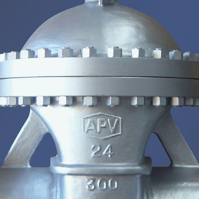
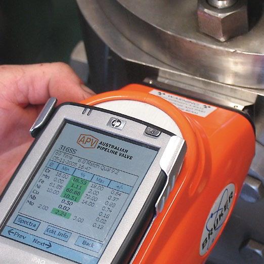
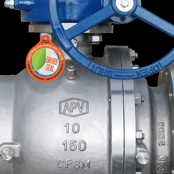
VALVE IDENTIFICATION
Each APV valve is identified with a nameplate. Below is an example.
9
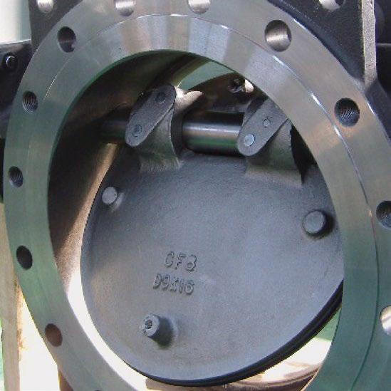
When performing any work, ordering spare parts, or requesting technical support, please refer to this tag. The serial number, the part number and numbers cast on the side of the valve body are keys to proper valve identification.
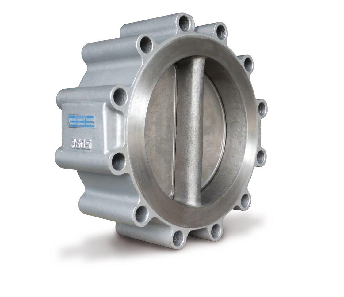
Australian Pipeline Valve - Installation, Operation and Maintenance Manual 5 WAFER PATTERN CHECK VALVES - ‘ASG’ & ‘AGW’ STYLE
CLASS BODY SEAT MODEL SIZE API594 MAX TEMP ASME B16.34 FLAPS SERIAL NO CWP@38ºC 9 7 1 8 4 3 2 5 6 ITEM DESCRIPTION 1 APV valve figure number which delineats the as-built valve type, body, trim, features, packing, NACE, etc. 2 Shell material (e.g. body) 3 Closure member material (e.g. flap) 4 Seat material 5 Rated pressure class as per ASME B16.34. Section 2 6 Nominal pipe size
Serial/batch number
Maximum Pressure Rating @ 38ºC (as per ASME B16.34/ API594)
7
8
Maximum Temperature
1.0 INSTALLATION
Piping should be properly aligned and supported to reduce mechanical loading on the end connections.
Install valve in system using proper size and type of mating flanges and appropriate gaskets (for FF or RF)or ring joint gaskets (for RTJ). Observe the following precautions:
• Do not install ASG/AGW series wafer check valves directly against another valve whereby the check valve discharges downstream directly into another valve.
• Do not install the valve whereby it directly discharges downstream into a tee or elbow fitting. Refer to Diagram 1.
• ASG/AGW check valves are not suitable for vertical downflow installations.
1.1 INSTALLATION POSITIONS
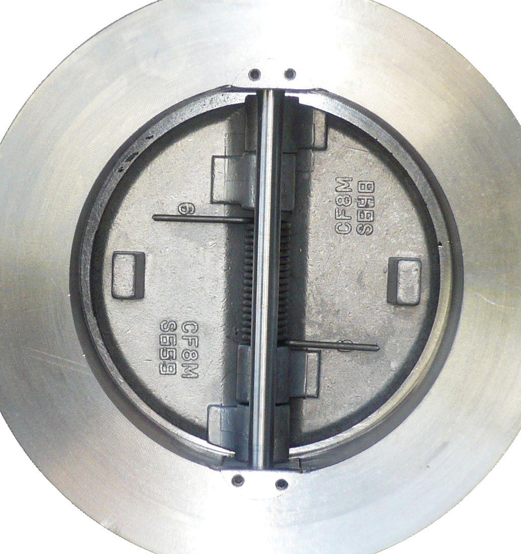
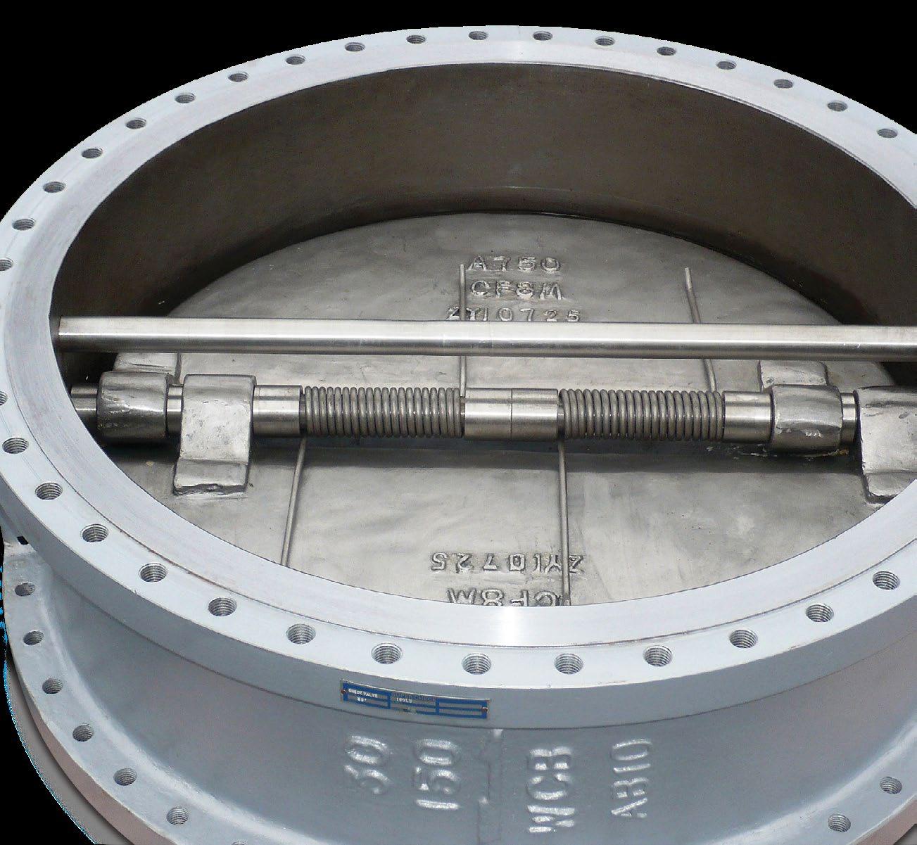
Check valves are unidirectional and have the direction of flow indicated on the valve body.
Supercheck dual flap check valves are recommended for use only in horizontal lines and vertical lines for upwards flow only.
1.2 PREPARATION FOR INSTALLATION
• Remove protective end caps or plugs and inspect valve ends for damage to flange faces.
• Thoroughly clean adjacent piping system to remove any foreign material that could cause damage to seating surfaces during valve operation.
• Verify that the space available for installation is adequate to allow the valve to be installed.
1.3 END CONNECTIONS
1.3.1 Flanged Ends
Check to see that mating flanges are dimensionally compatible with the flanges on the valve body and ensure sealing surfaces are free of debris.
Install the correct studs and nuts for the application and place the gasket between the flange facings.
Stud nuts should be tightened in an opposing criss-cross pattern in equal increments to ensure even gasket compression. See Diagram 5.
Australian Pipeline Valve - Installation, Operation and Maintenance Manual 6 WAFER PATTERN CHECK VALVES - ‘ASG’ & ‘AGW’ STYLE
1.4 CLEANING
Before installation, wash off any rust proofing solution coating with kerosene, or any hydrocarbon solvent product. Valve plates (flaps) should be checked to ensure they are free.
1.5 DIRECTION OF FLOW & INSTALLATION POSITION
The direction of flow in the line should coincide with the flow direction indicated by the cast ‘arrow’ on the body of the valve.
Dual plate check valves are designed for steady flow conditions and are not recommended for use near reciprocating pumps, but especially compressors, any pulsating devices or other types of physical/thermal shock-load applications. In this type of application, the check valve will not perform efficiently and will ultimately fail.
For vertical installation it is necessary to orientate the valve rib such that there is equal loading on both flaps. Refer Diagram 1. Additional pressure drop should be expected due to the weight of the discs.
In this position, the valve rib is perpendicular to the incoming horizontal piping which creates an unequal loading on the flaps. NO!
In this position, the valve rib is parallel to the incoming horizontal piping and creates an equal loading on the flaps.
YES!
DIAGRAM 1
Supercheck valves can be installed either horizontally or vertically. For vertical installations, dual plate check valves can only be installed with flow direction upward. In the vertical position, the outlet will be above the inlet.
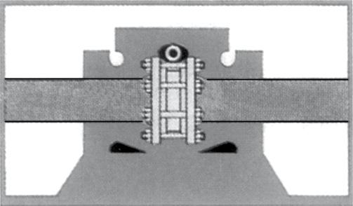
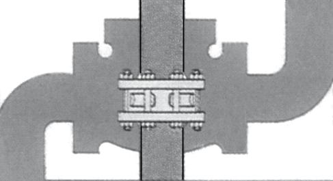
DIAGRAM 2
Australian Pipeline Valve - Installation, Operation and Maintenance Manual 7 WAFER PATTERN CHECK VALVES - ‘ASG’ & ‘AGW’ STYLE
Horizontal Flow Horizontal Flow
Horizontal Flow Horizontal Flow
➡➡ ➡➡ YES! YES!
1.6 HORIZONTAL PIPING
Insert valve into pipeline so that the Pin Retainers (plugs) on model ‘ASG’ are placed in an up and down position. In other words the central rib in the middle of the valve must be perpendicular to the flow. For model ‘AGW’ use the body profile or lifting lug as a guide but install the same way. Consult Diagram 1 and 2 for orientation positions.
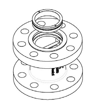
1.7 DISTANCE BETWEEN DUAL FLAP CHECK VALVE AND A BUTTERFLY VALVE
If you attach another valve to the outlet side of the Supercheck valve, ensure that there is enough distance between two valves so that the plates of the Supercheck check valve do not touch the disc of the other valve in the open position. For separating other valves such as butterfly valves, a spacer spool may be required to stop the disc interfering with the check valve flaps.
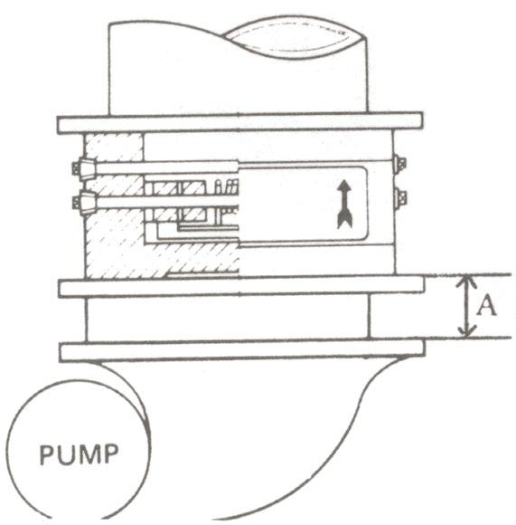
1.8 ORIENTATION OF DUAL FLAP CHECK VALVE TO PUMP DISCHARGE
When mounting the Supercheck valve near a pump, as indicated on Diagram 4, position so that the flow of the pump meets evenly with the two plates of the valve. The hinge pin of the Supercheck valve should be at right angles to the pump shaft. Ideally, for maximum service life keep distance ‘A’ more than 6 times the diameter of the pipe. For higher pressures the distances should be further. Consult Diagram 1 and 2 for orientation positions.
Australian Pipeline Valve - Installation, Operation and Maintenance Manual 8 WAFER PATTERN CHECK VALVES - ‘ASG’ & ‘AGW’ STYLE
Correct Incorrect Incorrect DIAGRAM 3
DIAGRAM 4
1.9 GASKETS
The opening end of the outlet side of Dual Flap Check valve is manufactured larger than the internal diameter of the pipe. Use a gasket that is either the same internal diameter of the dual flap Check outlet, or slightly larger. Most common spiral wound or CNAF pipe gaskets will fit, providing they are the same corresponding flange class rating as the valve it’s specified to. CNAF gaskets are only suitable up to 1400 kPa (200 psi). Ring joint gaskets are frequently specified in class 900 to 2500. The recommended tightening sequence is shown below in Diagram 5. Tighten in numerical order, gradually increasing torque with each sequence.
1.10 POST-INSTALLATION PROCEDURES
After installation, the line should be cleaned by flushing to remove any foreign material. When caustics are to be used to flush the line, additional flushing with clean water is required. The valve should be opened and closed after installation to ensure proper operating function. With the line pressurised, check the valve end connections and any body plugs for leaks.
2.0 OPERATION
The check valve operation is automatic and requires no assistance. When the flow exerts sufficient pressure against the disc to overcome the disc’s weight, the disc allows the flow to continue through the piping system. As pressure decreases, the disc lowers until it’s own weight forces it to seat. This prevents the possibility of a reversal in the flow.
Metal seated check valves are not zero leak devices and may “seep” in service. This type of valve should always be backed up with an isolation valve. Even soft seated valves require a small amount of back pressure to effect a seat. Similarly, to open the valve the cracking pressure depends on the spring tension. Low cracking pressure springs are available.
Australian Pipeline Valve - Installation, Operation and Maintenance Manual 9 WAFER PATTERN CHECK VALVES - ‘ASG’ & ‘AGW’ STYLE
1 7 4 5 3 8 26 ORDER OF TIGHTENING BOLTS DIAGRAM 5
3.0 MAINTENANCE
No periodic maintenance is necessary.
4.0 REPAIRS
Proper safety equipment and apparel should be worn when preparing to service a valve. Observe the general safety warnings throughout this catalogue and consult your safety and plant managers.
4.1 REPAIR INSTRUCTIONS
Due to the relatively low replacement cost of small diameter standard iron or carbon steel valves especially under 200 NB (8”), it is usually less expensive to replace the complete valve than to have maintenance personnel effect repairs. Refer to indicative bill of materials in Appendix A, Diagram 6, 7 and 7A. Design varies according to size, class, seat type, etc., hence refer to as-built drawing.
Gasket sealing surfaces should be scraped clean (avoid radial marks).
4.2 REMOVING VALVE FROM PIPELINE
Only one half of the stud bolts need to be removed (others can just be loosened) when removing the dual flap from the line. Of course for flanged or fully lugged valves all bolts should be removed.
4.3 DISASSEMBLY ASG SERIES
Unscrew the stop pin retainers (11) and (9) from the body (1). Remove stop pin (4) from body (1). Unscrew the hinge pin retainers (12) from the body (1). To remove hinge pins (3) maintain pressure on the spring (5) and withdraw hinge pin (3). Dis-assemble and remove springs (5), body lug bearings (8), plate lug bearings (7), spring bearings (6), plates (2), and support sleeves when fitted (10).
4.4 DISASSEMBLY AGW SERIES
Remove retaining screws (9) and retainer ring (14) (version A) and then slide out the entire cartridge supported by thrust bearing inserts (6) which can then be removed. Remove the plates (2) from hinge pin (3) taking careful note of the position of spring (5) and washers (7).
Unscrew the flange insert component using a special tool
Before attempting shaft extraction, be sure to press hand over springs. Failure to do this may result in personal injury due to the spring ‘launching’ itself unexpectedly once the shaft is pulled free of it. Always wear protective eye wear.
Australian Pipeline Valve - Installation, Operation and Maintenance Manual 10 WAFER PATTERN CHECK VALVES - ‘ASG’ & ‘AGW’ STYLE
AGW
THREADED RETAINER VERSION A/A1
4.5 ASSEMBLY ASG SERIES
a) Lay the body (1) down, with ‘downstream’ side of the body facing upward. Lay plates (2) inside the body (1) with the hinge lugs together and sealing surface down. If support sleeves are fitted they must be inserted into plates before placing into the body. Insert bearings (6), (8) and plate lug bearings (7) between the body and plate lugs respectively. Check the plates (2) and lug bearings for end play. If body plates are severely worn they should be replaced.
b) Valves with one spring, wind the spring (5) 180° in a clockwise direction. Place the wound spring (5) in position between the hinge lugs ensuring the convex side of the spring’s leg is against the plate. For valves with two springs, ensure that the convex side of the spring legs (long leg) are at the centre of each plate. While maintaining pressure on the spring (5), insert the hinge pin (3) into the body (1) passing it through the lug bearings (7) and (8), plates (2), spring (5), spring bearings (6).
c) First insert the pin stabilisers (9) (where applicable) then Teflon tape the threads of the hinge pin retainer, and screw the hinge pin retainers (12) into the body (1).
d) First insert the pin stabilisers (9) (where applicable) then insert stop pins (4) into the body (1). Teflon tape the threads of stop pin retainer (11) and screw the stop pin retainers into the body (1).
4.6 ASSEMBLY AGW SERIES
a) Lay the body down, with ‘downstream’ side of the body facing upward. First reassemble the entire cartridge unit in the reverse order shown in 4.3 above. The thrust bearing inserts (6) should house the stop pin (4) and the hinge pin (3). The hinge pin (3) should have plates (2), springs (5) and bearing/ washers (7) pre fitted.
Note: Valves with one spring, wind the spring (5) 180º in a clockwise direction. Place the wound spring (5) in position between the hinge lugs ensuring the convex side of the spring’s leg is against the plate. For valves with two springs, ensure that the convex side of the spring legs (long leg) are at the centre of each plate. While maintaining pressure on the spring (5), insert the hinge pin (3) into the body (1), plates (2), spring (5), bearings (7).
b) Finally the closure ring (version A) (14) and screws (9) (version A and B) should be fastened.
For AGW and ASG series: under no circumstances wind springs to gain a higher or lower torsional load. Special high and low torque springs are available for this purpose. Before attempting shaft extraction, be sure to press a hand over the disc spring. Failure to do this may result in personal injury due to the spring “launching” itself unexpectedly once the shaft is pulled free of it.
Australian Pipeline Valve - Installation, Operation and Maintenance Manual 11 WAFER PATTERN CHECK VALVES - ‘ASG’ & ‘AGW’ STYLE
WAFER PATTERN CHECK VALVES - ‘ASG’ & ‘AGW’
STYLE
APPENDIX
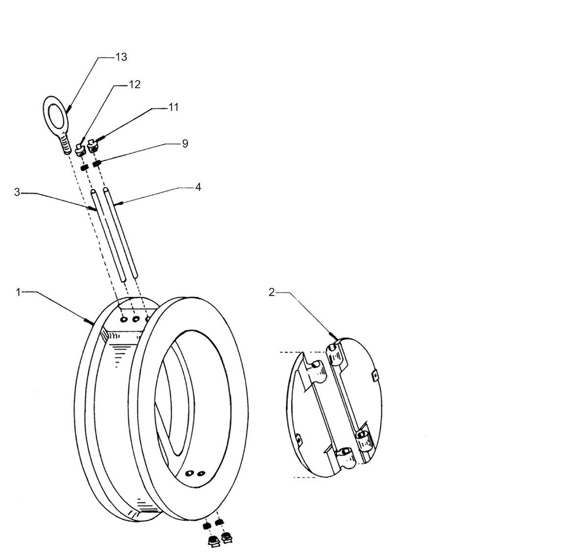
EXPLODED VIEW ‘ASG’ STYLE
DIAGRAM 6
Indicative drawing only, refer to as-built drawing. Drawing will vary according to size, class, materials, etc.
EXPLODED VIEW ‘AGW’ THREADED RETAINER STYLE
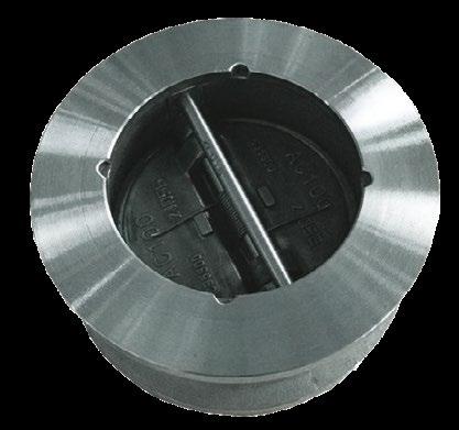
DIAGRAM 7
Indicative drawing only, refer to as-built drawing. Drawing will vary according to size, class, materials, etc.
Australian Pipeline Valve - Installation, Operation and Maintenance Manual 12
ITEM QTY DESCRIPTION 1 1 BODY 2 2 PLATES 3 1 HINGE PIN 4 1 STOP PIN 5 1 ~ 5 SPRINGS
2 PIN RETAINERS 7 2 ~ 8 BODY BEARINGS 7a 2 ~ 4 PLATE BEARINGS 7b 0 ~ 4 SPRING BEARINGS 13 1 EYE BOLT* 14 1 RETAINER RING† (THREADED) * Where required † Sits inside the mating flange gasket contact surface area on flange faces
6
ITEM QTY DESCRIPTION 1 1 BODY 2 2 PLATES 3 1 HINGE PIN 4 1 STOP PIN 5 2 ~ 5 SPRING 6 3 ~ 5 SPRING BEARING 7 2 ~ 4 PLATE LUG BEARING 8 2 ~ 4 BODY LUG BEARING 9 4 PIN STABILISERS* 10 2 SUPPORT SLEEVES* (≤ 600NB) 11 2 HINGE PIN RETAINER PLUGS 12 2 STOP PIN RETAINER 13 1 LIFTING EYE BOLT* * Where fitted 5 7 10 6 8 7b 7a 5 7 4 3 6 2 14† 1 (threaded) Gasket Sealing Area
EXPLODED VIEW ‘AGW’ ALLEN KEY RETAINER STYLE
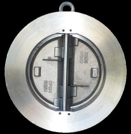
DIAGRAM 7A
Indicative drawing only, refer to as built drawing. Drawing will vary according to size, class, materials, etc.
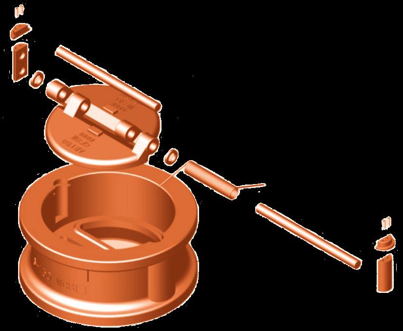
DIAGRAM 8
Indicative drawing only, refer to as built drawing. Drawing will vary according to size, class, materials, etc.
Australian Pipeline Valve - Installation, Operation and Maintenance Manual 13
WAFER PATTERN CHECK VALVES - ‘ASG’ & ‘AGW’ STYLE
Body Pin holder Retainer Screw Hinge pin Spring Bearing Disc Stop pin 3 5 13 1 6 4 2 7 9 9 7 6a† ITEM QTY DESCRIPTION 1 1 BODY 2 2 PLATES 3 1 HINGE PIN 4 1 STOP PIN 5 1 ~ 5 SPRINGS 6 2 PIN HOLDER 6a 1 PIN HOLDER RETAINERS*
2 ~ 8 BEARINGS
2 SCREWS (2/4) 13 1 EYE BOLT*
Where required † Rebated into bore where required to allow smaller pin holder channel, thereby avoiding overlap into flange face gasket contact area. † Gasket Sealing Area Spiral wound section of gasket size
7
9
*
a Gas test not performed as standard on cast iron body
API598 does not require gas test on steel valves but APV performs it
b 5.5 bar minimum test pressure. (Higher test pressure may be required to energise resilient seat in high pressure classes/larger sizes).
c Since API 598 does not specify a leakage rate for resilient seated check valves, many manufacturers use the metal seated check valve leakage rate. However, APV demands as close as possible to tight shut off as per API 598 resilient seated (ISO 5208-A) Note in higher classes in smaller sizes and all classes in larger sizes, 3 up to 10 water drips a minute is accepted.
d For check valves, gas test is not required as per API 598, but APV does perform it.
1cc = 16 drops, 1ml = 16 drops
Australian Pipeline Valve - Installation, Operation and Maintenance Manual 14 WAFER PATTERN CHECK VALVES - ‘ASG’ & ‘AGW’ STYLE TABLE 1 TABLE 2 Class 125-150 Spring Cracking Pressure kPa (PSI) Valve Coefficient Cv Valve Size Std. Torque Valve Size Class 125-300 mm (in) mm (in) 50 (2”) 1.58 (0.23) 50 (2”) 75 65 (2 1/2”) 1.79 (0.26) 65 (2 1/2”) 95 80 (3”) 1.45 (0.21) 80 (3”) 191 100 (4”) 1.52 (0.22) 100 (4”) 377 127 (5”) 1.24 (0.18) 127 (5”) 483 150 (6”) 0.96 (0.14) 150 (6”) 821 200 (8”) 1.31 (0.19) 200 (8”) 1,590 250 (10”) 1.24 (0.18) 250 (10”) 2,920 300 (12”) 1.17 (0.17) 300 (12”) 4,470 350 (14”) 1.03 (0.15) 350 (14”) 5,870 400 (16”) 1.10 (0.16) 400 (16”) 8,690 450 (18”) 1.03 (0.15) 450 (18”) 10,940 500 (20”) 0.90 (0.13) 500 (20”) 14,290 600 (24”) 0.69 (0.10) 600 (24”) 23,000 750 (30”) 0.55 (0.08) 750 (30”) 37,200 900 (36”) 0.55 (0.08) 900 (36”) 59,000 1050 (42”) 0.34 (0.05) 1050 (42”) 92,000 1200 (48”) 0.41 (0.06) 1200 (48”) 126,000 Cracking pressures shown are a rough guide and valve cannot be used as a relief valve. The use of low torque springs should only be used when unique conditions are evaluated. TABLE
Wafer Check Valve Standard APV Allowable Leakage Rates for Closure (Seat) Tests API 598 VALVE SIZE METAL SEATED WAFER CHECK VALVES SOFT SEATED WAFER CHECK VALVES NB NPS LIQUID TEST (cc/min) GAS TEST (bubbles/min) LIQUID TEST (cc/min) GAS TEST a (bubbles/min) APV API 598 API 598 APV API 598 APV a API 598 ≤50 ≤2 3 6 Not required per API598 d 0 c Not specified c 2 b Not required per API598 d 65 2.5 3.75 7.5 Not required per API598 d 0 c Not specified c 2 b Not required per API598 d 80 3 4.0 9 Not required per API598 d 0 c Not specified c 2 b Not required per API598 d 100 4 6.0 12 Not required per API598 d 0 c Not specified c 2 b Not required per API598 d 125 5 7.5 15 Not required per API598 d 0 c Not specified c 2 b Not required per API598 d 150 6 9.0 18 Not required per API598 d 0 c Not specified c 2 b Not required per API598 d 200 8 12.0 24 Not required per API598 d 0 c Not specified c 2 b Not required per API598 d 250 10 15.0 30 Not required per API598 d 0 c Not specified c 3 b Not required per API598 d 300 12 18.0 36 Not required per API598 d 0 c Not specified c 3 b Not required per API598 d 350 14 21.0 42 Not required per API598 d 0 c Not specified c 4 b Not required per API598 d 400 16 24.0 48 Not required per API598 d 0 c Not specified c 4 b Not required per API598 d 450 18 27.0 54 Not required per API598 d 0 c Not specified c 5 b Not required per API598 d 500 20 30.0 60 Not required per API598 d 0 c Not specified c 6 b Not required per API598 d 600 24 36.0 72 Not required per API598 d 0 c Not specified c 7 b Not required per API598 d
3
valves and is not
as per API 598.
required
WARRANTY
1. LIMITED WARRANTY: Subject to the limitations expressed herein, Seller warrants that products manufactured by Seller shall be free from defects in design, material and workmanship under normal use for a period of one (1) year from installation but in no case shall the warranty period extend longer than eighteen months from the date of sale. This warranty is void for any damage caused by misuse, abuse, neglect, acts of God, or improper installation. For the purpose of this section, “Normal Use” means in strict accordance with the installation, operation and maintenance manual. The warranty for all other products is provided by the original equipment manufacturer.
2. REMEDIES: Seller shall repair or replace, at its option, any non-conforming or otherwise defective product, upon receipt of notice from Buyer during the Manufacturer’s warranty period at no additional charge. SELLER HEREBY DISCLAIMS ALL OTHER EXPRESSED OR IMPLIED WARRANTIES, INCLUDING, WITHOUT LIMITATION, ALL IMPLIED WARRANTIES OF MERCHANTABILITY AND FITNESS OR FITNESS FOR A PARTICULAR PURPOSE.
3. LIMITATION OF LIABILITY: UNDER NO CIRCUMSTANCES SHALL EITHER PARTY BE LIABLE TO THE OTHER FOR INCIDENTAL, PUNITIVE, SPECIAL OR CONSEQUENTIAL DAMAGES OF ANY KIND. BUYER HEREBY ACKNOWLEDGES AND AGREES THAT UNDER NO CIRCUMSTANCES, AND IN NO EVENT, SHALL SELLER’S LIABILITY, IF ANY, EXCEED THE NET SALES PRICE OF THE DEFECTIVE PRODUCT(S) PURCHASED DURING THE PREVIOUS CONTRACT YEAR.
4. LABOR ALLOWANCE: Seller makes NO ADDITIONAL ALLOWANCE FOR THE LABOR OR EXPENSE OF REPAIRING OR REPLACING DEFECTIVE PRODUCTS OR WORKMANSHIP OR DAMAGE RESULTING FROM THE SAME.
5. RECOMMENDATIONS BY SELLER: Seller may assist Buyer in selection decisions by providing information regarding products that it manufacturers and those manufactured by others. However, Buyer acknowledges that Buyer ultimately chooses the product’s suitability for its particular use, as normally signified by the signature of Buyer’s technical representative. Any recommendations made by Seller concerning the use, design, application or operation of the products shall not be construed as representations or warranties, expressed or implied. Failure by Seller to make recommendations or give advice to Buyer shall not impose any liability upon Seller.
6. EXCUSED PERFORMANCE: Seller will make a good faith effort to complete delivery of the products as indicated by Seller in writing, but Seller assumes no responsibility or liability and will accept no back-charge for loss or damage due to delay or inability to deliver, caused by acts of God, war, labor difficulties, accidents, inability to obtain materials, delays of carriers, contractors or suppliers or any other causes of any kind whatever beyond the control of Seller. Under no circumstances shall Seller be liable for any special, consequential, incidental, or indirect damages, losses, or expense (whether or not based on negligence) arising directly or indirectly from delays or failure to give notice of delay.
Australian Pipeline Valve - Installation, Operation and Maintenance Manual 15 WAFER PATTERN CHECK VALVES - ‘ASG’ & ‘AGW’ STYLE
Australian Pipeline Valve - Installation, Operation and Maintenance Manual 12 NOTES

© Copyright Australian Pipeline Valve 1990 - 2023 Edition
Catalogues, photos, brochures and technical publications are the exclusive property of Australian Pipeline Valve.
Any unauthorised reproduction in total or in part, shall result in prosecution. Products and data sheets in this publication are subject to change at anytime without notice. Australian Pipeline Valve reserves the right to carry out amendments to products and materials.
Australian Pipeline Valve - Installation, Operation and Maintenance Manual 13
NOTES


www.australianpipelinevalve.com.au AUSTRALIAN PIPELINE VALVE® HEAD OFFICE 70-78 Stanbel Road Salisbury Plain South Australia 5109 Telephone +61 (0)8 8285 0033 email: admin@australianpipelinevalve.com.au If you have any requirements in the field of valves, please contact us for a prompt response. Continuous development of Australian Pipeline Valve products may necessitate changes in the design or manufacture process. Australian Pipeline Valve reserves the right to effect any such changes without prior notice. © Australian Pipeline Valve 1990 - 2024 Edition LOCAL DISTRIBUTOR/AGENT IOM Supercheck Checkwafer ASG AGW