“Australian Pipeline Valve produces isolation, control and flow reversal protection products for severe and critical service media in utility, steam, pipelines, oil & gas and process industries. APV valves and pipeline products form the most competitive portfolio in the market.”
APV FAMILY OF BRANDS RANGE - CATALOGUES
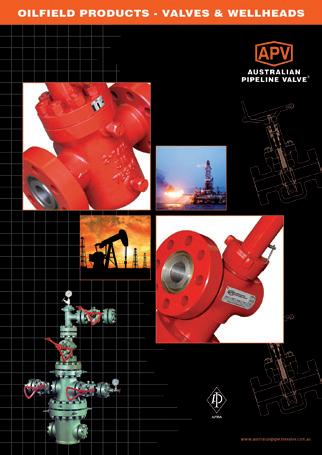
Oilfield Products Valves & Wellheads
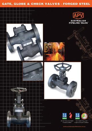
Gate, Globe & Check Valves - Forged Steel
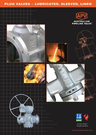
Plug Valves Lubricated, Sleeved & Lined
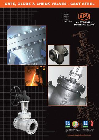
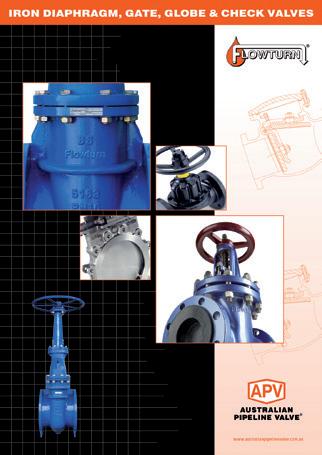
Gate, Globe & Check Valves - Cast Steel
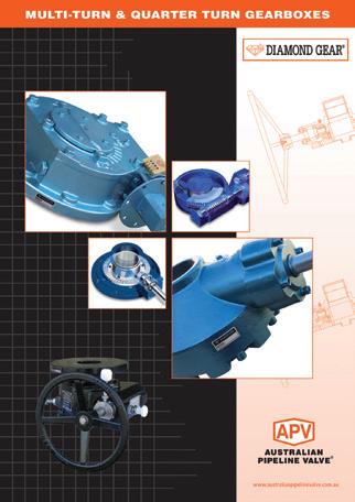
Diamond Gear Gearboxes
Flowturn Gate, Globe & Check Valves
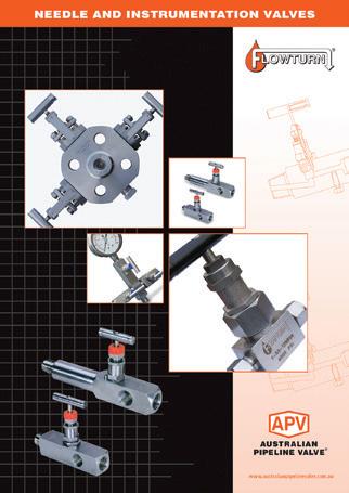
Flowturn Instrument Valves
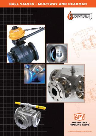
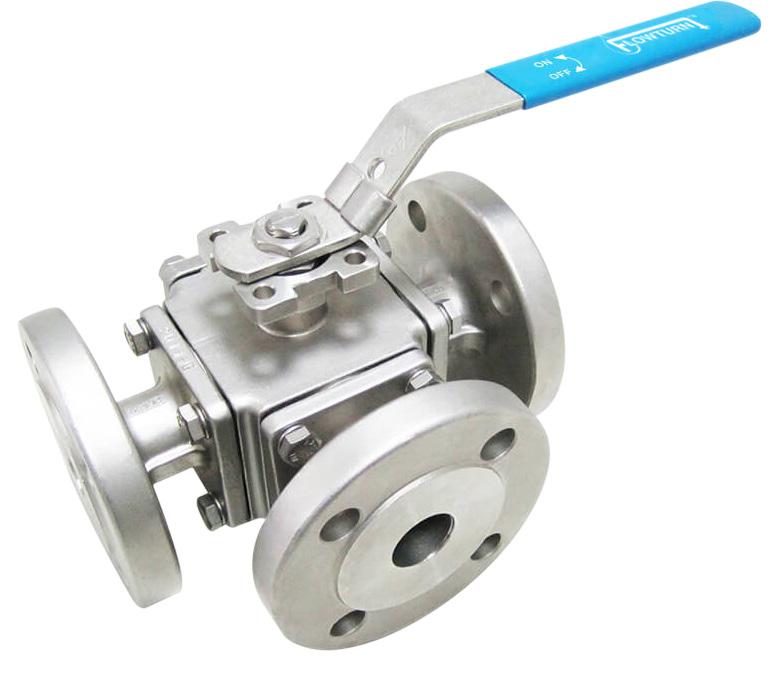
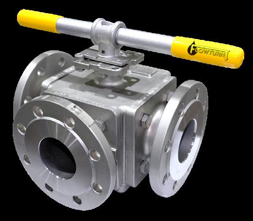
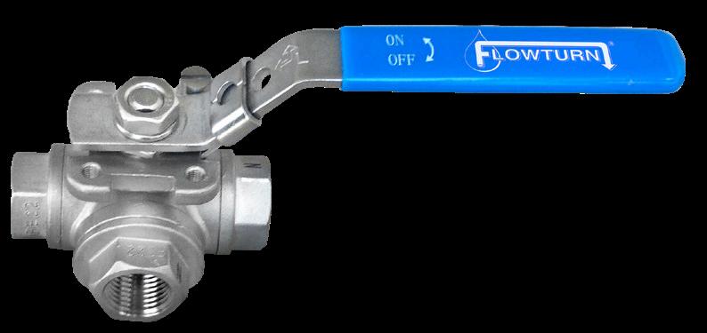
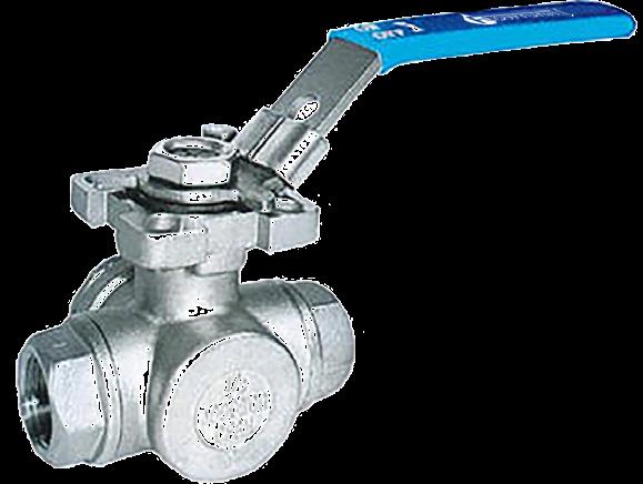
Flowturn Ball Valves Multiway & Deadman
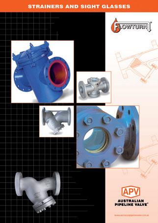
Flowturn Strainers & Sight Glasses
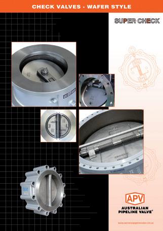
Supercheck Wafer Check Valves
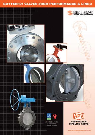
Superseal Butterfly Valves
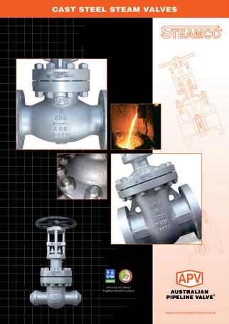
Steamco Steam Valves
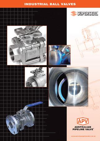
Superseal
Industrial Ball Valves
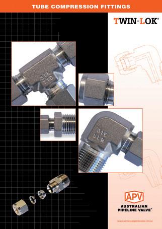
TwinLok Tube Fittings
Uniflo Check Valves
Torqturn Actuators
Ball Valves Floating & Trunnion Mounted
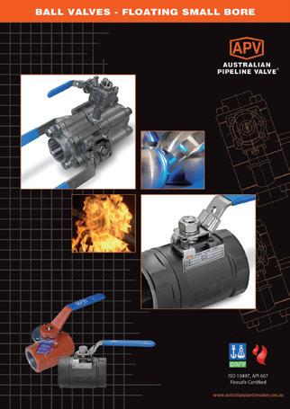
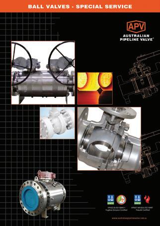
Ball Valves Floating Small Bore Ball Valves Special Service
Product Brochure
INTRODUCTION
The majority of this information is common knowledge to experienced valve users. When properly installed in applications for which they were designed, Australian Pipeline Valve (APV) valves will give long reliable service. This instruction is only a guide for installation and operation on standard service and covers general maintenance and minor repairs. A professional APV approved valve engineering facility should be utilised for reconditioning or major repairs.
Note
We recommend that this entire document be read prior to proceeding with any installation or repair. Australian Pipeline Valve and it’s parent company take no responsibility for damage or injury to people, property or equipment. It is the sole responsibility of the user to ensure only specially trained valve repair experts perform repairs under the supervision of a qualified supervisor.
RESPONSIBILITY FOR VALVE APPLICATION
The User is responsible for ordering the correct valves. The user is responsible for ensuring APV Valves are selected and installed in conformance with the current pressure rating and design temperature requirements. Prior to installation, the valves and nameplates should be checked for proper identification to ensure the valve is of the proper type, material and is of a suitable pressure class and temperature rating to satisfy the requirements of the service application.
Do not use valves in applications where either the pressure or temperature is higher than the allowable working values. Also valves should not be used in service media if not compatible with the valve material of construction, as this will cause chemical attacks, leakage, valve failure.
RECEIVING INSPECTION AND HANDLING
Valves should be inspected upon receipt to ensure:
- Conformance with all purchase order requirements.
- Correct type, pressure class, size, body and trim materials and end connections.
- Any damage caused during shipping and handling to end connections, hand wheel or stem.
The User is advised that specifying an incorrect valve for the application may result in injuries or property damage. Selecting the correct valve type, rating, material and connections, in conformance with the required performance requirements is important for proper application and is the sole responsibility of the user.
SAFETY INFORMATION
The following general safety information should be taken in account in addition to the specific warnings and cautions specified in this manual. They are recommended precautions that must be understood and applied during operation and maintenance of the equipment covered in this I.O.M.
Never attempt to disassemble a valve while there is pressure in the line. Ensure both upstream and downstream pressures are removed. Disassemble with caution in case all pressures are not relieved. Even when replacing stem packing, caution is necessary to avoid possible injury.
To prevent valve bending, damage, inefficient operation, or early maintenance problems, support piping on each side of the valve. When handling gases/fluids that could cause damage to human health, the environment or property, the necessary safety precautions to prevent risk must be taken.
• A valve is a pressurised mechanism containing energised fluids under pressure and consequently should be handled with appropriate care.
• Valve surface temperature may be dangerously too hot or too cold for skin contact.
• Upon disassembly, attention should be paid to the possibility of releasing dangerous and or ignitable accumulated fluids.
• Ensure adequate ventilation is available for service.
This manual provides instructions for storing, general servicing, installation and removal of ball valves. APV and it’s resellers refuse any liability for damage to people, property or plant as well as loss of production and loss of income under any circumstances but especially if caused by: Incorrect installation or utilisation of the valve or if the valve installed is not fit for the intended purpose. It is the sole responsibility of the user to ensure the valve type and materials are correctly specified.
SCOPE OF INSTALLATION ACCORDING TO THE TYPE OF FLUID (DANGEROUS FOR THE ENVIRONMENT OR HUMAN HEALTH)
Group 1 Classification
- The incorporation of additional safety elements “Double Packing” (utilising a stem extension) is recommended for the range of products included in Group 1.
- The use of valves without additional safety devices in Group 1 will be the responsibility of the user or the purchaser, as well as the advisability of installing leakage detection systems.
Group 2 Classification
- Carbon steel valves will not be used in corrosive fluid lines.
DURING OPERATION TAKE INTO ACCOUNT THE FOLLOWING WARNINGS:
a- Graphite/Graphoil packing and body gasket is very brittle, any impacting, twisting or bending should be avoided.
b- The valve’s internal parts such as ball, stem, seats, seals, gaskets shall be handled with care avoiding scratches or surface damage.
c- All tools and equipment for handling internal critical sealing parts shall be soft coated.
d- Valves can be fitted with gaskets or seals in PTFE, Buna, Viton, etc., hence high temperatures will damage sealing components.
e- Never part open valve, valve must be full open of full closed to avoid seal damage.
For all operations make reference to position number on part list of the applicable drawing listed.
1.0 SCOPE
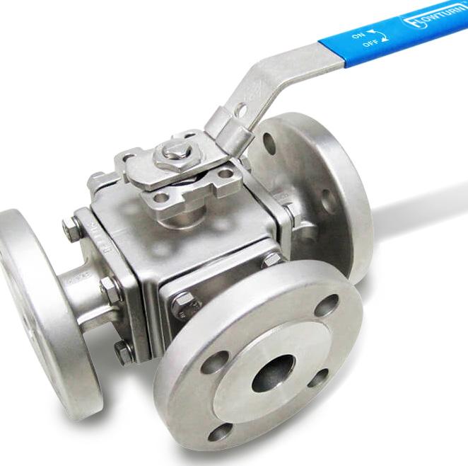
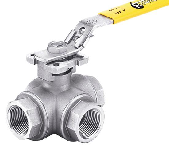
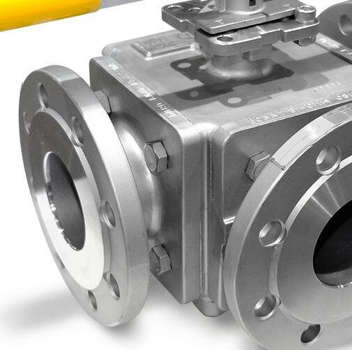
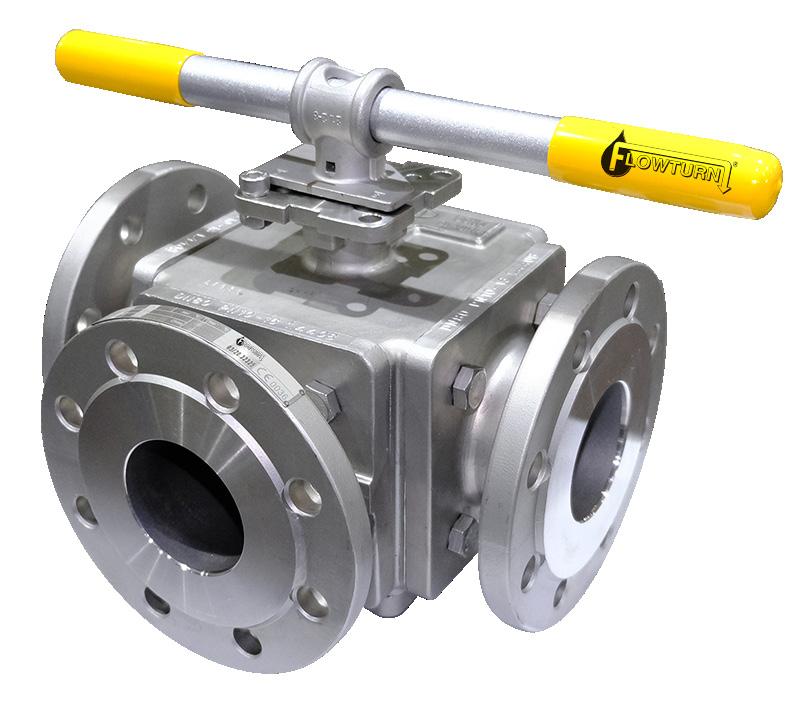
This manual describes the methods of installation and maintenance for multi-way ball valves, which are designed to fit between ANSI Class 150, Class 300 PN10, PN16, PN40 flanges or with buttweld ends or with screwed ends. Multi-way valves are generally not firesafe and not for throttling use.
The operating temperature is within -29°C to 200°C for PTFE, RTFE or TFM1600 seat and sealing. Other seat and sealing operating temperature shall be checked with APV.
The nominal pressure (PN) rating or ASME rating indicates the body pressure/temperature however, the seats and seals reduce the temperature and pressure rating. Refer to Appendix G.
1.1 ENVIRONMENTAL CONSIDERATIONS
According to ISO 14000 regulations and the environmental policy of APV, the recyclability of the components that form part of APV valves is as follows:
Recyclable components: Metal parts, PTFE (hard), plastic plug (low-density polyethylene).
Non-recyclable components: PTFE mixed with other compounds (glass-fiber, graphite, etc.), nylon, graphite and graphite mixed with metal.
1.2 STORAGE
1.2.1
Temporary Storage
If valves are to be stored before installation, the following should be observed:
a) Keep the valves wrapped and protected as shipped from the manufacturer.
b) Do not remove the protective end covering until the valve is ready for installation. This will reduce the possibility of foreign material damaging the internal valve components.
c) Valves stored outdoors should be positioned such that water does not accumulate in the valve body.
1.2.2 Long Term Storage
If valves are to be stored more than one year, they should be prepared in the following manner:
a) Remove the packing and apply a preservative to the packing chamber.
b) Do not remove the protective end covering.
c) Do not store the valves outdoors.
1.3 PREPARATION
a) Remove the valve end protection.
b) Prior to shipment, a preservative/corrosion inhibitor may have been applied to the inner body of the valve. This preservative/corrosion inhibitor can be removed with a solvent provided the solvent used does not affect the seats/seals used in the valve.
c) The inside of the valve should be inspected and blown out with compressed air. Adjacent piping must be clean and free from debris to prevent damage to the valve.
d) To prevent valve distortion, inefficient operation or early maintenance problems, support piping on each side of the valve.
e) Make sure the valve is positioned such that there is sufficient space so that the hand wheel is easily and safely reached and there is enough clearance for the stem when the valve is open.
f) Install the valve according to the flow indicator on the valve body where applicable.
2.0 INSTALLATION
For flange end valve, stud nuts should be tightened in an opposing criss-cross pattern in equal increments to ensure even gasket compression. Refer Appendix A.
The following procedure is required to be followed for correct installation.
a) Before installation confirm the marking (rating, size and material) on the valve body and nameplate. Ensure the valve is suitable for the service which it is being used.
b) Body bolts and nuts on valve shall be checked and retightened if necessary in case loosened during installation.
c) Remove valve end protectors and ensure gasket faces are free from damage. Tighten all bolts between mating flanges and valve equally paying careful attention to properly tighten bolts. Ensure you rotate tightening procedure (opposing bolts sequentially) gradually increasing torque. Refer to Appendix Table 3 for tightening sequence.
d) Prior to installation of valve, ensure the line is completely flushed to remove any debris as soft seated ball valves are easily damaged. Filters or strainers should be installed upstream to protect soft seated valves.
e) Valves will operate at any angle horizontally or vertically, although it is recommended you install valves in a vertical position with stem pointing upwards for ease of operation, inspection and accessibility.
f) Before installation, please make sure if the marking on the valve (such as pressure flow direction, material, etc.) is in accordance with the application requirement.
g) Remove the protective plastic cap and clean or flush the valves.
h) Prior to mounting, flush and/or clean the pipeline to remove all accumulated extraneous matters which could cause damage to the seats and ball surface.
i) Make sure the flow direction, which direction mark is shown on the handle. The valve may be fitted in any position on the pipeline.
j) Use conventional sealant (e.g. Teflon) on the threads and gasket (for flanged ends), as required for service type.
k) For screwed end valves, apply wipe wrench on the end cap of the valve only while tightening. Tightening by using the valve body or handle can seriously damage the valve.
l) For screwed end valves, unions to be installed before each end for easy installtion and disassembly of the valve.
m) The pipeline shall be free of tension after installation.
n) When fitting an actuator, operating torque requirements will vary depending on the length of time between cycle, media in the system line pressure and type of valve seat. Figures in Appendix A show torques for TFM1600 or PTFE seats with clean cold water as the media and valve toqrue of maximum pressure differential.
Actuation use: where a ‘stop lock cap’ (see Appendix B & D) is used, it must remain on the valve when fitting an actuator
It is possible with the ball in closed condition, the sealed cavity inside the valve body is filled with liquid. If this liquid is not released by partially opening the valve and the valve is subject to a temperature increase, excessive pressure can occur inside the body. Self-relieving pressure seats can prevent pressure build up. However, to prevent a pressure build-up inside the valve exceeding the design pressure, the piping design, installation, or operation procedure of end user should prevent this situation from occurring.
2.1 INSTALLATION POSITIONS
3 & 4 Seated Multi-way Ball valves are bi-directional, and therefore may be installed in either direction. In some cases, ball valves such as ‘metal to metal’ seated and low temperature valves may be unidirectional, in which case the direction of flow will be indicated on the valve body.
2.2 PREPARATION FOR INSTALLATION
• Remove protective end caps or plugs and inspect valve ends for damage to threads, weld ends or flange faces.
• Thoroughly clean adjacent piping system to remove any foreign material that could cause damage to seating surfaces during valve operation.
• Verify that the space available for installation is adequate to allow the valve to be installed and to be operated.
2.3 END CONNECTIONS
Stud nuts should be tightened in an opposing criss-cross pattern in equal increments to ensure even gasket compression.
2.3.1 Threaded Ends
Check condition of threads on mating pipe. Apply joint compound to the male end of joint only. This will prevent compound from entering the valve flowpath.
2.3.2 Flanged Ends
Check to see that mating flanges are dimensionally compatible with the flanges on the valve body ensure sealing surfaces are free of debris. Install the correct studs and nuts for the application and place the gasket between the flange facings.
2.3.3 Socket weld Ends
Remove all debris, grease, oil, paint, etc., from the pipe that is to be welded into the valve and from the valve end connections.
Insert the pipe into the valve end connection until it bottoms out in the socket weld bore. Withdraw the pipe 1/16” so that a gap remains between the pipe and the bottom of the socket weld bore to prevent cracks (ASME B16.11). Tack the pipe into the valve and complete the fillet weld.
WELDING INSTRUCTIONS
• Local welding regulations and specification must be complied with when carrying out welding work.
• Remove any paint and rust around the weld area on the pipe and welded end of the ball valve.
• Check that the ball valve is correctly positioned and aligned with the pipeline.
• Where weld connection is close to seat area, due to short length of the welded ends there is a risk that the soft inserts may be destroyed during the welding work. Hence the following procedure is advised: -
Use temperature measuring strips to check that the temperature does not rise beyond the permissible limits (160°C). The strips must be fitted to the connection near the soft inserts. These temperature measurements strips are designed so that, when a type-dependent temperature is reached, the colour irreversibly changes from white to black. The temperature measurement strip must be monitored constantly throughout the welding work. If any change of colour is noticed, the welding work must be interrupted immediately and the weld allowed to cool.
2.3.4 Buttweld End Valves
Clean the weld ends as necessary and weld into the line using an approved weld procedure. Make sure the pipe and valve body material given on the valve body or nameplate is compatible with the welding procedure. (Refer our compatibility cross reference chart for equivalent pipe, valve & fittings grades at the Technical section of our website). Soft seats can be damaged during welding, take steps to ensure valve is not over heated, especially smaller size valves (see above caution note).
2.4 VALVE INSTALLATION BY WELDING
Leave valves in the full open position during installation, welding and post-weld heat treatment. This will reduce temperature transmission to soft seats. After welding completion, open the valve and flush line to clean out any foreign matter. Valves over 65 NB ( 2 1/2”) have minimal risk of temperature damage to seats. For valves up to 80 NB (3”) the welding temperature can adversely affect the PTFE and elastomer components. Follow the welding instructions above and use temperature measuring strips to monitor temperature. It will be the responsibility of the operator to ensure valves are kept cool during welding and then post-weld testing of the valve should be performed. Larger size valves over 80 NB (3”) are less likely to transmit heat to seat and stem packing during welding but still care should be taken. Depending on class, valves under 50 NB (2”) should have pup ends fitted to avoid seat damage. If not fitted ensure valve body temperature is kept cool. Temperatures over 180°C can damage seats & seals.
The responsibility for welding of the valves into piping systems is that of those performing the welding. Refer to ASME B31.1, B31.3 etc. Written welding procedures covering all attributes of the process and materials to be welded shall be in accordance with Section IX of the ASME Boiler and Pressure Vessel Code and any additional requirements from the applicable piping code including any possible necessary localised post weld heat treatment depending on material specifications.
3.0 OPERATION
3.1 MANUAL OPERATION
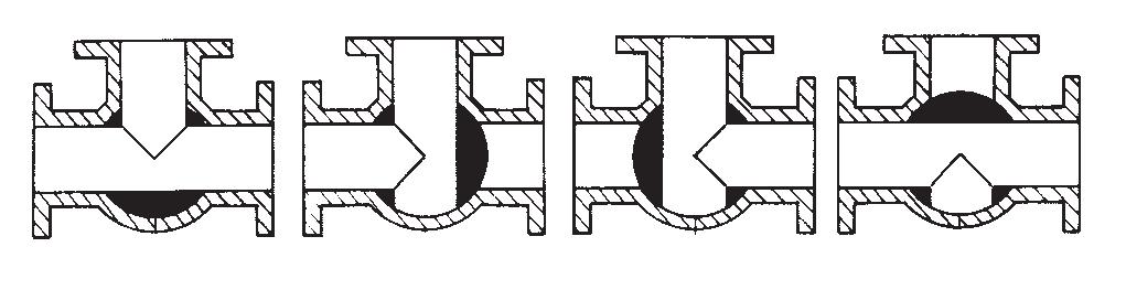
The manual operation for the proper flow plan is done by turning the handle a 1/4 turn (90 degrees turn). Visual indication of position is done by visual inspection of the markings on the top of the stem. Refer to as built drawing for permissible flow path configurations. The 4 seat design allows tight shutoff to flow in either direction or dead end service, regardless of the position of the valve in-line.
3.2 OPERATION INSTRUCTION
Valve adjustment is performed through lever handle/gear operation. The follow direction from can be identified by the stem top indication pattern (see Figure 1 and 2). For gear operated valves, the flow is indicated by the arrow-indicator (see Figure 3 and 4). See Appendix F for other flow position options. Multi-way ball valves allow 0°, 90°, 180°, 270°, 360° turning based on different flow paths, see Appendix F. The valve can be operated in 90° turn increments.
Floating valves without supplementary upstream relief hole in ball cannot be used for unstable fluids which, if trapped in the body cavity (valves in closed position) can be subject to the risk of increasing of pressure due to the increasing of temperature. If required, the purchaser must specify an upstream relief hole. Valves without fugitive emission extensions cannot be used for toxic or dangerous medium with the risk of dispersion in the environment. For fluids like oxygen, hydrogen or chlorine where the contact with oil or grease can create explosions valves that have not been properly cleaned, degreased and sealed in suitable boxes cannot be used. Avoid any kind of contamination until the moment of use. The same precautions have to be applied to valves for cryogenic services.
FIG 1. 3-WAY T-PORT BALL VALVES
FIG 2. 3-WAY L-PORT BALL VALVES
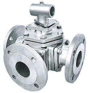
FIG 3. GEAR OPERATED 3-WAY T-PORT BALL VALVES
FIG 4. GEAR OPERATED 3-WAY L-PORT BALL VALVES
LIQUIDS WITH HIGH FLUID VELOCITY
When ball valves must be operated frequently on liquid with very high velocity, check with manufacturer for appropriate advice to minimise the possibility of seat deformation, especially when working pressure and temperature is reaching maximum ranges.
Avoid using the valves at partially open or partially closed position. Using partially opened valves may lead to seat deformation and leakage. Standard ball valves are generally not recommended for throttling service. The fluid flow can damage the leading edge of the ball and/or damage or deform the resilient ball seats causing leakage. High fluid velocity and/or the presence of solids particles in the media will reduce the lifetime of seat and ball during throttling applications.
3.3 AUTOMATED OPERATIONS
Valves with actuators should be checked for actuator/valve alignment. Angular or linear mis-alignment will result in high operational torque and permanent packing failure. Refer to as built drawing for theoretical torque ratings which are subject to variations depending on the length of time between cycles and the media in the system.
Breakaway torque is that force which must be exerted to cause the ball to begin to open. Operating torque requirements will vary depending on the length of time between cycles, media in the system and line pressure. As actual torque test should be done at full differential pressure before sizing actuator media type, lubricity & temperature should be factored in.
4.0 MAINTENANCE
Only APV approved repairer should attempt to perform work on APV valves.
Valves should be periodically checked at least once every 3 months, but depending on service, criticality and frequency of use, more regular checking may be required.
Packing leakage could result in personal injury. Valve packing is tightened prior to shipping but may require adjustment to meet specific service conditions. If valve does not fully close, damage to the seat and body will result due to the venturi effect resulting in high pressure erosion. Flush or remove the valve at next opportunity.
Ball valves can trap pressurised fluid in ball cavity when in the closed position. Prior to maintenance, relieve the line pressure and put ball in the open position.
A good program of inspection and maintenance cannot be overstressed. It is recommended that the valve be periodically and at least partially stroked/function tested to ensure the valve functions and prevent seizure/sticking of any mating surfaces. Duration depends on service, criticality etc. However it also must be factored in that if there are impurities or particulates in the line each operation could reduce seat life proportionately. Periodic inspection of critical leak-path areas such as body/bonnet joint, end connections, seating surfaces, and around the stem packing should be a requirement.
The most common area for leakage is around the stem packing, this is usually due to wear and can normally be stopped by adjusting the packing. This procedure is performed by turning gland bolts or nut in very small increments until leakage stops. If leakage cannot be halted by adjusting packing, repacking of the valve is indicated.
With self-wiping ball/seats, APV valves have a long, trouble free life, and maintenance is seldom required. But, when necessary, valves may be refurbished, using a small number of components, none of which require machining.
APV valves are designed for easy service and assembly in the field. The following checks will help to extend valve life, or reduce plant problems.
APV Ball Valves utilise live-loaded stem seals featuring Belleville washer (disc springs) that maintain constant pressure on the stem seal area even under a wide range of pressure and temperature fluctuations. However, regular stem packing tightening is required. Occasional replacement of packing may also be required dependant on service conditions.
4.1 GLAND PACKING
In case of slight leakage from the gland, nut can be lightly tightened up without effecting torque. For torques, see Appendix A. Do not over tighten as it will increase torque of the valve and could result in damage. If there is leakage, open and close the valve 30° to 60°, if there is still leakage, replace packing as per 4.1.1.
Do not attempt to repack or replace stem while the valve is in service! Only graphite packing and gaskets are to be used for oil & gas service, PTFE is not firesafe.
4.1.1 Stem Leakage – Stem Packing Replacement
The most common point for leakage is around the stem and packing this leakage can normally be stopped by adjustment of the packing gland. If this does not stop the valve leakage, the valve will have to be repacked.
The system and valve MUST be depressurised before attempting any repair work. After removing all pressure from the valve and draining the system the following procedure should be used to repack the valve.
1. Remove nuts or screw from the lever. Remove the lever and lock plate. Remove the gland plate bolts or nut and remove the gland plate and gland. If the gland retainer is a double nut type then remove both nuts and anti vibration washer.
2. Remove old packing with the proper tool, taking care not to scratch or damage the stem of stuffing box. Note, the stem design is anti-blow out so the stem cannot be removed up through the top of the valve.
3. Clean and inspect stem, stuffing box, and gland. If any scratches, nicks, or corrosion is found, the parts should be replaced.
4. Slide each packing ring over the stem and into packing chamber. Ensure if “v-type” PTFE packing set, the packing is correct way up. See figure 5A (note the correct orientation of the v-type packing). If v-type packing, a genuine packing set must be used. Carefully tap each ring into place and continue installing rings until the recommended number of rings have been installed. A thin smear of molybdenum sulfide anti-seize grease may be used on the stem and packing chamber wall for packing lubrication.
5. Replace gland, gland, and gland plate bolts or nut. Tighten until a reasonable torque is applied to lightly compress packing. Lubricate stem and cycle valve through a couple of complete cycles.
6. If slight stem leakage occurs after system is pressurised, continue tightening gland until leakage stops. There is also a PTFE seal ring/bearing and an elastomer o-ring. However, these parts can only be replaced during complete disassembly of the valve. Should replacement of packing fail to prevent the leakage, complete reconditioning of the valve may be required. Examine the disc springs (Belleville washers) for damage. If in good condition, tighten the gland nut until disc springs are firmly compressed, then back the nut off 1/16th of a turn. If damaged, dismantle the stem down to the gland, fit new disc springs with their outer edges touching, replace and retighten using the gland nut. Further maintenance necessitates dismantling of the valve.
Personal injury may result from sudden release of any process pressure. APV recommends the use of protective clothing, gloves and eye wear when performing any installation or maintenance. Isolate the valve from the system and relieve pressure prior to performing maintenance. Disconnect any operating lines providing air pressure, control signals or electrical power to actuators.
4.2 BODY SEAL
Sealing between two body segments is provided with a gasket (Teflon or graphite) In case of slight leakage the fastening bolts (or threaded body connection) can be lightly tightened up (flange body version). Refer bolting torques in Appendix A table 2.
If a gasket seal is disturbed while removing or adjusting gasketed parts, APV recommends installing a new gasket while reassembling. A proper seal is required to ensure optimum operation.
4.2.1 Body Gasket Tightening
If after tightening body bolts, leakage continues, replacement of gasket is recommended. A new gasket is recommended anytime the valve is disassembled. The following procedure shown in 4.3 is recommended for the replacement of the gasket and other trim components. Also refer to Appendix A for torques.
4.3
INSPECTION AND REPLACEMENT OF TRIM COMPONENTS
Disassembly: -
1. Place the valve in the half open position and remove all pressure and drain the system. Make sure that leakage of any residual material is caught in an appropriate container and disposed of properly.
2. For gear operator or power actuator operated: - remove the bolt fastening the gearbox or power actuator. Remove the gear operator or power actuator. Remove the bolt fastening the yoke or yoke nut (depending on size/class).
3. For lever operated: - remove the screw or fastening components of the lever. Remove the lever. Remove the retainer/lock washer and the stop plate.
4.4
LEAKING FROM THE VALVE SEAT
a. After long-term valve operation and endurance of force, the resilience of the ball seat weakens, resulting in decreased pressure against the ball, thus leading to leakage. Further tightening the body bolts as per 4.2 above may tighten the seat seal further. Do not tighten more than torques shown in Appendix A.
b. After long-term valve operation and endurance of force, the ball seat or the ball can become scratched and therefore leakage occurs. Replace seats. Also, refer sections 4, 5 & 6.
4.4.1 Disassembly
Refer Appendix B to E for indication of parts. Refer to as-built drawing from APV for actual bill of material.
a. Place valve in half-open position and flush the line to remove any hazardous material from the valve body.
b. Place the valve in close position, remove both counter flange bolts & nuts and lift valve from line.
c. Remove handle nut, handle or actuator set, stop-lock-cap (where applicable), stem nut, Belleville washer, gland nut, bush and stem packing.
d. Remove body bolt or threaded end cap to allow end cap to be separated from body, remove body gasket.
e. Make sure ball in “closed” position, thus the ball can be taken out easily from body, then take out body ball seat.
f. Push stem down into the body cavity and remove, then remove the stem seal-ring and V-stem packing from the body.
Use care to avoid scratching the surface of stem and packing chamber.
4.4.2 Reassembly
a. Reassembly process is reverse sequence of disassembly.
b. Clean and inspect all parts, full replacement of all soft parts (seats and seals) are strongly recommended.
c. Tighten the body bolt or screwed end cap crosswise (in the case of flanged body design) using the stipulated torque figure (see Appendix A).
d. Tighten the stem nut (using the stipulated torque figures (see Appendix A).
e. Cycle the valve slowly with gentle back and forth motion to build gradually to full quarter turn.
f. Test the valve before placing it back in the line for service.
5. REBUILDING & TEST
Before rebuilding, check that all the correct components are available and that they are fit for reassembly. When rebuilding, cleanliness is essential to allow long valve life and provide cost effective maintenance. Hydrostatic test body at 1.5 times the valve’s working maximum working pressure in open position. After installation, the pipeline system may be subject to a system test not to exceed the above mention pressure. Hydrostatic test the seats 1.1 times maximum working pressure in all desired closed position. Pneumatic test the seat at 5.5 Bar (80 PSI) in the desired closed position. If the valve is used for high pressure air or gas service a high pressure seat and body test is recommended using Nitrogen.
Do not use air for high pressure test as an explosive reaction can occur.
Note
No body or stem seals are reusable. Care must be taken to avoid scratching the seats and seal during installation.
Caution must be taken with valves that have been in hazardous media. They must be decontaminated before assembly by relieving the line pressure and flushing the line with the valve in the partially open position. Protective clothing and face shield, gloves, etc. must be used for this operation.
5.1 DISASSEMBLY OF VALVE (REMOVE FROM THE LINE)
1. With the valve in the open position, undo body bolt nuts (or unscrew in case of threaded body design) to separate valve body and ends.
2. Once the body and the ends have been separated, remove the body seal.
3. Make sure the ball is in the closed position, thus the ball can be taken out easily from the body.
4. Once the ball is removed from the body take out the seats.
5.2 REMOVING STEM FINAL DISASSEMBLY
1. Remove handle by removing from the body take out the seats.
2. Remove the stem nut, Belleville washers, gland, stem packing and stem gaskets.
3. Push the stem down into the body cavity to remove. Once removed, take off the o-ring and thrust washer. Refer to as-built drawing & exploded bill of material sample drawings in Appendix B,C,D.
5.3 REASSEMBLY
Repolish or replace the ball and stem required. Replace all soft parts, refer Table A and Appendix A to E. Ensure the ball orientation is as required and matches the markings on the stem or gearbox shown in 3.2. Re-assemble in the reverse order of 5.1, 5.2. Refer 4.2.1 and Appendix A for body bolts (where applicable) and stem nut re-tightening.
6.0 REPAIR KITS
Repair kits are available from APV. Table A shows what the kits consist of. When ordering a repair kit, please be sure to specify type and size of the valve.
When repairing a valve, use only APV authorised spare parts including bolts and nuts. If additional items are required, (body and ends) it is normally recommended to replace the complete valve. Components from different valve series should never be used with the repair of any other valve. If the valve is altered in any way, no liability can be accepted by APV.
APPENDIX A
TORQUES
TABLE 1
BODY & STEM NUT TORQUE REQUIREMENTS (NM) BV509A FLANGED BODY VALVES 150/300
CLASS PN10/16/25
BODY STUD LUBRICATION
• Re-tightening of body bolts (with system de-pressurised) and gland packing bolting is permissible, if leakage occurs in these areas.
• The use of copper-based Anti-seize grease for body and packing stud lubrication and molybdenum disulfide anti-seize grease for stem packing lubrication is recommended.
Depending on the gasket type and model, tightness may vary. Over-tightening will increase valve seating torque.
Close to Open Torques at Differential Pressures shown (rP), Standard Seats (TFM1600 &
minimum 30% is recommended.
TABLE 1H
T-PORT BV509
TABLE 1I
SEAT BREAK TORQUE VALUES L-PORT BV509
Break to Open Torques at Differential Pressures shown (rP), Standard Seats (TFM1600 &
APPENDIX A CONT.
TABLE 1J
SEAT BREAK TORQUE VALUES T-PORT BV509A Break to Open Torques at Differential Pressures shown (rP), Standard Seats
ALL MODELS
Other seat break torques as ratio/percentage of BTO:
Run to open .3
Run to close .3
End to open .7
End to close .75
Break to close .9
1L
APPENDIX B
BV-509 SERIES
DN15~50 (1/2”~2”) DN15~50 (2 1/2”~4”)
1/2~2”
2-1/2~4”
FLOW PATTERN: T-PORT L-PORT
APPENDIX C
Dimensional use only. Refer to actual as-built drawing for top view schematic as larger sizes and classes vary in design.
Example only, refer to as-built drawing for bill of material & torques.
APPENDIX E
SL8142-FZ SERIES
APPENDIX E CONT.
SL8142-FZ SERIES
1
2”
Example only, refer to as-built drawing for exploded bill of material & torques.
APPENDIX F
FLOW PATTERNS BV509/BV509A/SL8142-FZ
T PORT FLOW PATTERNS
L PORT FLOW PATTERNS
CONSIDERATIONS OF TECHNICAL RISK/ LIMIT OF LIABILITY TO CLIENT FOR BALL VALVES
Australian Pipeline Valve don’t consider in our design the following factors of risk:
1. Australian Pipeline Valve ‘Standard’ ball valves can be used in a temperature range between -28.8 to +200°C. (Note, pressure limitations apply above 38°C refer to Pressure/Temperature charts.) For service temperatures below -28.8°C ball valve construction materials shall be submitted to an impact test at the minimum service temperature. For temperatures outside of the range of -28.8°C to +200°C ball valves have to be provided with seats, seals and body material able to withstand the temperature degree required.
2. The onus is on the customer to specify all materials of construction and service conditions. Australian Pipeline Valve shall assume standard materials and conditions if not otherwise specified.
3. Australian Pipeline Valve ‘Standard’ ball valves are not equipped with devices suitable to avoid internal over-pressures caused by incorrect operations of process or by-fluids & liquids subjected to an increase of volume and/or pressure (these devices, such as the over-pressure hole in the ball or safety seats are available upon request).
4. Australian Pipeline Valve ‘Standard’ ball valves are not designed with special devices to withstand a sudden thermal jump (thermal shock).
5. In general Australian Pipeline Valve ‘Standard’ ball valves are not mechanically designed to bear overloads due to exceptional atmospheric or natural phenomenon’s (such as earthquakes).
6. In general Australian Pipeline Valve ‘Standard’ ball valves are not designed to bear loads on flanges, on pipe connections or pipeline.
7. In general Australian Pipeline Valve ‘Standard’ ball valves can’t withstand ice inside their bodies (in this case user must specify the optional stem extension for insulating, avoiding the presence of residual product inside the valve).
8. Australian Pipeline Valve ‘Standard’ ball valves are not suitable for low temperature service below -29°C (-20°F) unless provided with cryogenic stem extension and other modifications (available on request).
9. Australian Pipeline Valve ‘Standard’ ball valves are suitable for ‘industrial’ oxygen (not medical) service when supplied degreased and packed in polyethylene bags only.
10. The compatibility between ball valves construction materials and medium is selected by the user. The user is ultimately responsible for verifying the compatibility between medium and materials.
11. Abrasive or dirty service, high temperature service, low temperature service, vacuum service, near zero pressure service and other special applications should be clearly stated when requesting quotation.
12. Floating valves without supplementary upstream relief hole in ball cannot be used for unstable fluids which, if trapped in the body cavity (valves in closed position) can be subject to the risk of increasing of pressure due to the increasing of temperature. If required, the purchaser must specify an upstream relief hole.
13. Valves without fugitive emission extensions cannot be used for toxic or dangerous medium with the risk of dispersion in the environment.
14. For fluids like oxygen, hydrogen or chlorine where the contact with oil or grease can create explosions valves that have not been properly cleaned, degreased and sealed in suitable boxes cannot be used. Avoid any kind of contamination until the moment of use. The same precautions have to be applied to valves for cryogenic services.
BALL VALVE START-UP
Before installing the ball valve onto the pipe-line it is mandatory for the user to verify the compatibility of the ball valve with service conditions (medium, temperature and pressure). With reference to standard ball valves held in stock the reseller and end user will have to assure themselves of the compatibility with the use of conditions required by the customer. Australian Pipeline Valve ball valves must be only used for on-off (fully open/fully closed) service.
Before using the ball valve in a potential explosive atmosphere it’s necessary: -
• To verify the compatibility between the ball valve and the zone in which the ball valve should be installed.
• To foresee the pipe-line ground condition on which the ball valve should be installed.
• To check that the temperature of the ball valve surface is not higher than the flammable point of the atmosphere in which the ball valve is installed (in this case specify an insulating cover device for the valve and an extension for the wrench)
• Before installing ball valves with welding ends to make sure that the process of welding is carried out in accordance with all the safety requirements of the classified zone.
• To avoid mechanical knocks during the installation that may cause sparks.
Australian Pipeline Valve cannot be held responsible for damage caused by use of the product especially if it is improper use or modified.