

www.australianpipelinevalve.com.au INSTALLATION, OPERATION & MAINTENANCE MANUAL API6A MUD GATE VALVE X-DM STYLE
COMPLETE PRODUCT LINE
“Australian Pipeline Valve produces isolation, control and flow reversal protection products for severe and critical service media in utility, steam, pipelines, oil & gas and process industries. APV valves and pipeline products form the most competitive portfolio in the market.”
View our catalogues at www.australianpipelinevalve.com.au AUSTRALIAN PIPELINE VALVE BRAND RANGE - CATALOGUES APV FAMILY OF BRANDS RANGE - CATALOGUES
Oilfield Products Valves & Wellheads Gate, Globe & Check Valves - Forged Steel Plug Valves Lubricated, Sleeved & Lined Gate, Globe & Check Valves - Cast Steel Diamond Gear Gearboxes Flowturn Gate, Globe & Check Valves Flowturn Instrument Valves Flowturn Ball Valves Multiway & Deadman Flowturn Strainers & Sight Glasses Supercheck Wafer Check Valves Superseal Butterfly Valves Steamco Steam Valves Superseal Industrial Ball Valves TwinLok Tube Fittings Uniflo Check Valves
Actuators
Valves Floating & Trunnion Mounted Ball Valves Floating Small Bore Ball Valves Special Service Product Brochure Contact us for your local stockist/distributor
Torqturn
Ball

Introduction 2 Safety Information 3 1.0 Installation 4-5 1.1 Installation positions 4 1.2 Preparation for installation 4 1.3 End connections - installation 4-5 2.0 Overview 6-7 2.1 Construction 6 2.2 Application for mud gate valves 6 2.3 Applications 6 2.4 Seat elastomers 7 2.5 Pressure ratings of valve 7 3.0 Operation 7-8 4.0 Maintenance Overview 8-9 4.1 Gate and seat replacement 8 4.2 Stem packing replacement 9-18 4.3 Routine maintenance 19 5.0 Disassembly, Minor Maintenance & Reassembly 10-14 5.1 Tools required for maintenance & repair 10 5.2 Disassembly & minor maintenance 10-12 5.3 Disassembly & minor maintenance 12-14 6.0 Troubleshooting 15 Appendix 1 - Bill of materials 16-18 Appendix 2 - API6A Material service categories & rating levels 19-23 API6A MUD GATE VALVE - X-DM STYLE INDEX Australian Pipeline Valve - Installation, Operation and Maintenance Manual 1
INTRODUCTION
The majority of this information is common knowledge to experienced valve users. When properly installed in applications for which they were designed, Australian Pipeline Valve (APV) valves will give long reliable service. This instruction is only a guide for installation and operation on standard service and covers general maintenance and minor repairs. A professional APV approved valve engineering facility should be utilised for reconditioning or major repairs.
Note
We do recommend however that this entire document be read prior to proceeding with any installation or repair. Australian Pipeline Valve and it’s parent company take no responsibility for damage or injury to people, property or equipment. It is the sole responsibility of the user to ensure only specially trained valve repair experts perform repairs under the supervision of a qualified supervisor.
RESPONSIBILITY FOR VALVE APPLICATION
The User is responsible for ordering the correct valves. The user is responsible for ensuring APV Valves are selected and installed in conformance with the current pressure rating and design temperature requirements. Prior to installation, the valves and nameplates should be checked for proper identification to ensure the valve is of the proper type, material and is of a suitable pressure class and temperature rating to satisfy the requirements of the service application.
Do not use valves in applications where either the pressure or temperature is higher than the allowable working values. Also valves should not be used in service media if not compatible with the valve material of construction, as this will cause chemical attacks, leakage, valve failure.
RECEIVING INSPECTION AND HANDLING
Valves should be inspected upon receipt to ensure:
- Conformance with all purchase order requirements.
- Correct type, pressure class, size, body and trim materials and end connections.
- Any damage caused during shipping and handling to end connections, hand wheel or stem.
The User is advised that specifying an incorrect valve for the application may result in injuries or property damage. Selecting the correct valve type, rating, material and connections, in conformance with the required performance requirements is important for proper application and is the sole responsibility of the user.
API6A MUD GATE VALVE - X-DM STYLE Australian Pipeline Valve - Installation, Operation and Maintenance Manual 2
SAFETY INFORMATION
The following general safety information should be taken in account in addition to the specific warnings and cautions specified in this manual. They are recommended precautions that must be understood and applied during operation and maintenance of the equipment covered in this I.O.M
To avoid injury, never attempt disassembly while there is pressure either upstream or downstream. Even when replacing gaskets, caution is necessary to avoid possible injury. Disassemble with caution in case all pressures are not relieved.
To prevent valve bending, damage, inefficient operation, or early maintenance problems, support piping on each side of the valve. Warning, certain gases and fluids could cause damage to human health, the environment or property, hence the necessary safety precautions to prevent risk should be taken.
This manual provides instructions for storing, general servicing, installation and removal of gate valves. APV and it’s resellers refuse any liability for damage to people, property or plant as well as loss of production and loss of income under any circumstances but especially if caused by: Incorrect installation or utilisation of the valve or if the valve installed is not fit for intended purpose. It is the sole responsibility of the user to ensure the valve type and materials are correctly specified.
DURING OPERATION TAKE INTO ACCOUNT THE FOLLOWING WARNINGS:
a- Graphite/Graphoil packing and body gasket is very brittle, any impacting, twisting or bending should be avoided.
b- The valve’s internal parts such as disc, stem, seats, seals, gaskets shall be handled with care avoiding scratches or surface damage.
c- All tools and equipment for handling the internal parts shall be soft coated or else take extreme care, especially on machined mating surfaces and with soft parts.
d- Valves can be fitted with gaskets or seals in PTFE, Buna, Viton, etc., hence high temperatures will damage sealing components.
For all operations make reference to position number on part list of the applicable drawing listed.
Australian Pipeline Valve - Installation, Operation and Maintenance Manual 3 API6A MUD GATE VALVE - X-DM STYLE
1.0 INSTALLATION
Where applicable, piping should be properly aligned and supported to reduce mechanical loading on the end connections.
1.1 INSTALLATION POSITIONS
Gate valves are usually bi-directional and therefore may be installed in either direction. In some cases, gate valves may be uni-directional, in which case the direction of flow will be indicated on the valve body.
1.2 PREPARATION FOR INSTALLATION
• Remove protective end caps or plugs and inspect valve ends for damage to threads, socket weld bores or flange faces.
• Thoroughly clean adjacent piping system to remove any foreign material that could cause damage to seating surfaces during valve operation.
• Verify that the space available for installation is adequate to allow the valve to be installed and to be operated.
Ensure sufficient clearance for the stem in the full open position may cause the valve to be inoperable. Inadequate clearance for valve may add mechanical loading to the valve ends. Sufficient clearance should be allowed for threaded valves to be ‘swung’ during installation.
1.3 END CONNECTIONS - INSTALLATION
1.3.1 Threaded Ends
Check condition of threads on mating pipe.
Apply joint compound to the male end of joint only. This will prevent compound from entering the valve flowpath.
1.3.2 Flanged Ends
Check to see that mating flanges are dimensionally compatible with the flanges on the choke and ensure sealing surfaces are free of debris.
Install the correct studs and nuts for the application and place the flange gasket between the flange facings.
Australian Pipeline Valve - Installation, Operation and Maintenance Manual 4 API6A MUD GATE VALVE - X-DM STYLE
Stud nuts should be tightened in a an opposing criss-cross pattern in equal increments to ensure proper gasket compression.
1.3.3 Buttweld Ends
Clean the weld ends as necessary and weld into the line using an approved weld procedure. Make sure the pipe and body material given on the nameplate is compatible with the welding procedure.
1.3.4 Valve Installation by Welding
Leave valves assembled and in the lightly closed position during installation, welding and post-weld heat treatment. This will prevent the valve seat from floating or distorting during the process. After welding completion, open the valve and flush line to clean out any foreign matter.
Stem seal leakage could result in personal injury. Valve stem area is tested prior to shipping but should be again checked to ensure no leakage.
Check the stem sealing area for pressurised process fluids even after the valve has been removed from the line, particularly when removing seals or fittings.
Personal injury may result from sudden release of any process pressure. APV recommends the use of protective clothing, gloves and eyewear when performing any installation or maintenance.
Isolate the valve from the system and relieve pressure prior to performing maintenance.
Disconnect any operating line providing air pressure, control signals or electrical power to actuators.
When removing or adjusting gasketed parts, APV recommends installing a new gasket before reassembling. A proper seal is required to ensure optimum operation.
Australian Pipeline Valve - Installation, Operation and Maintenance Manual 5 API6A MUD GATE VALVE - X-DM STYLE
2.0 OVERVIEW
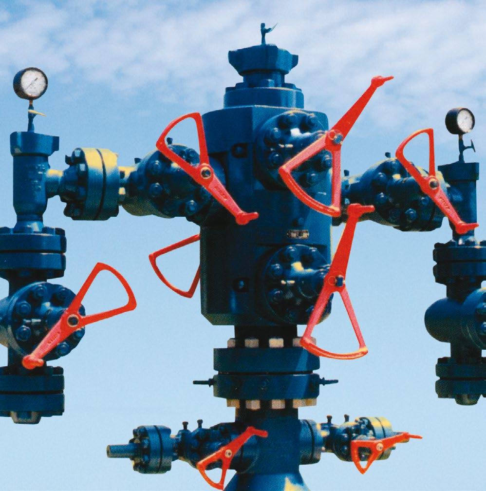
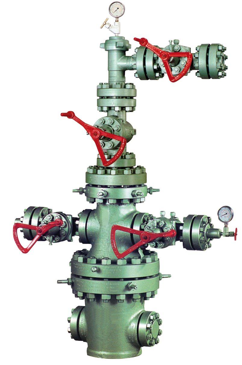
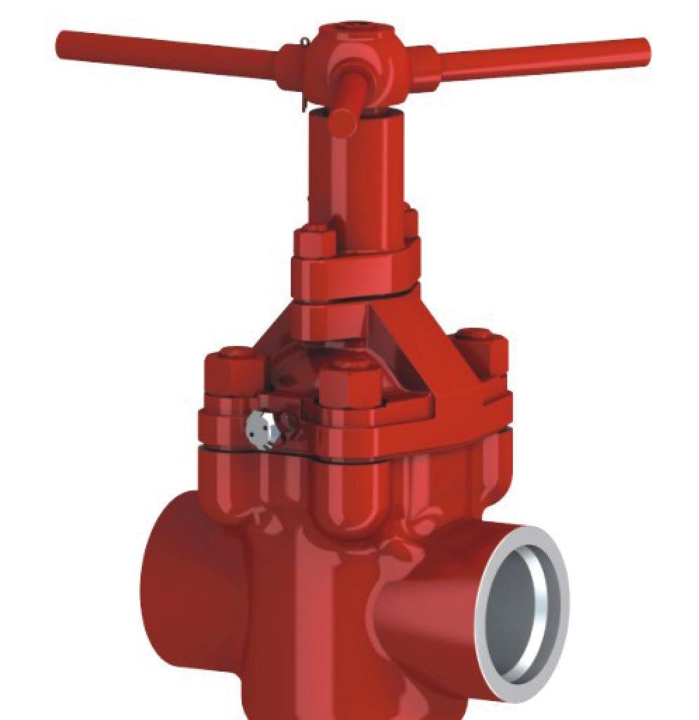
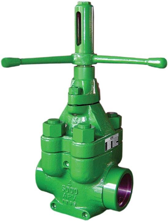
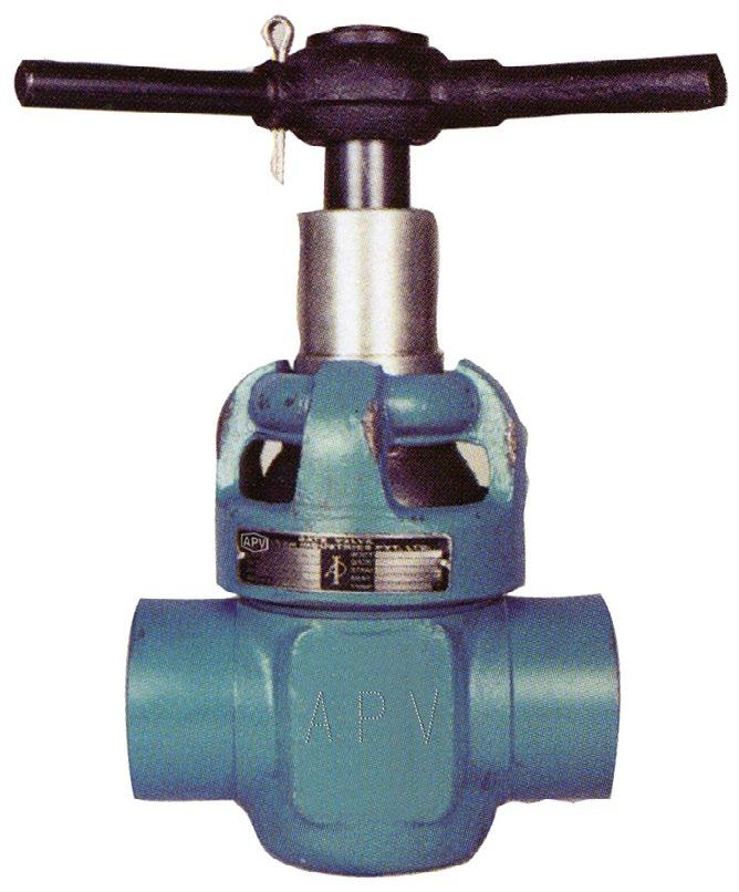
The mud gate valve, with superior design features and precision workmanship is proven to meet the harsh drilling requirements in today’s oilfields.
The valve conforms to the standard dimensions and pressure rating of 3000 and 5000 PSI working pressure, and temperature service up to 204°C (400°F).
The valve standard trim includes 410 or 316SS gates, 410 or 316SS stems and BUNA N seats, optional trims are available which include Ni plated, stellited, carbon steel, monel and aluminium bronze gates. Seats are offered in Viton and Hypalon, and optional 17-4 pH or 303SS stem is available. 410SS is used for high H2S service.
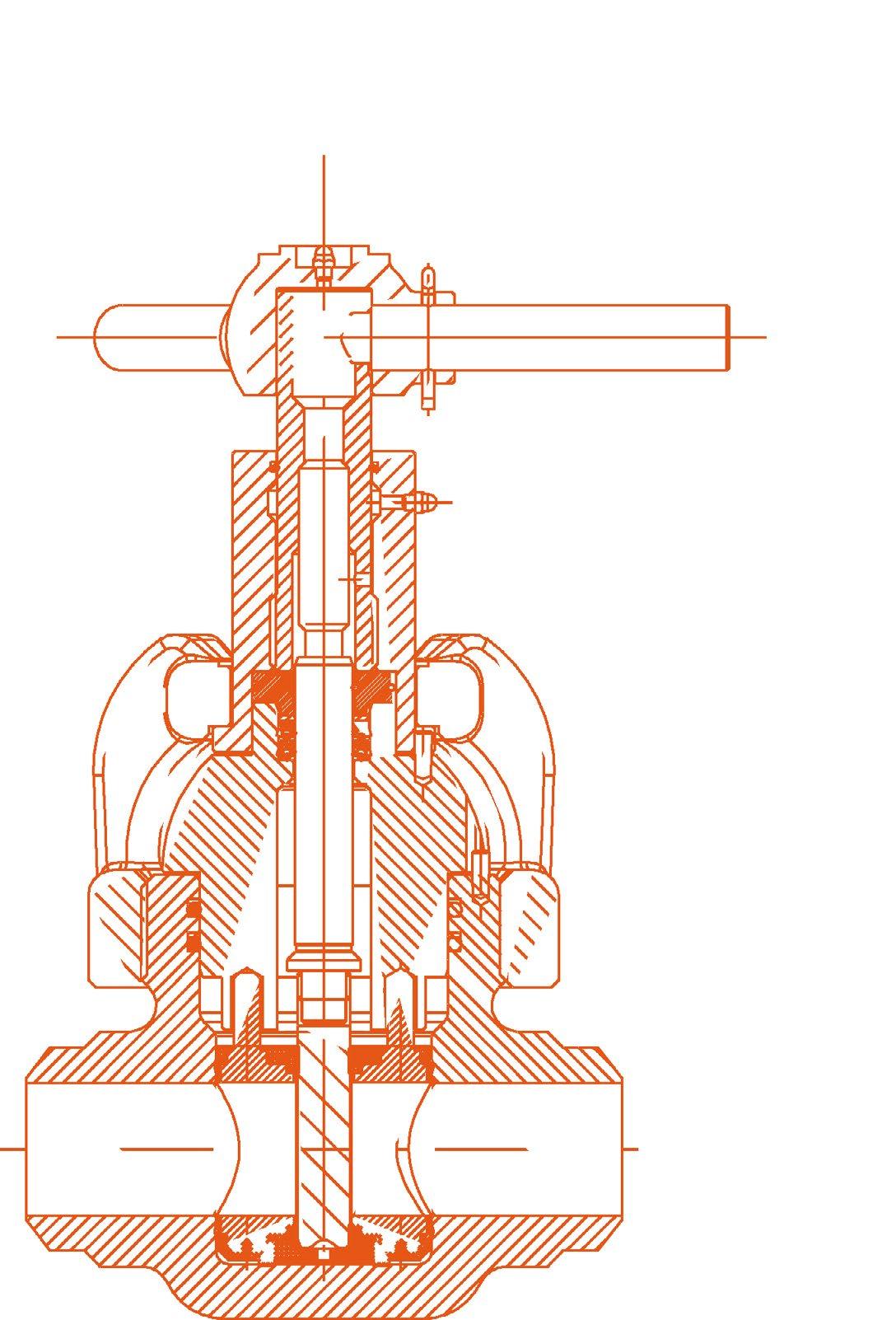
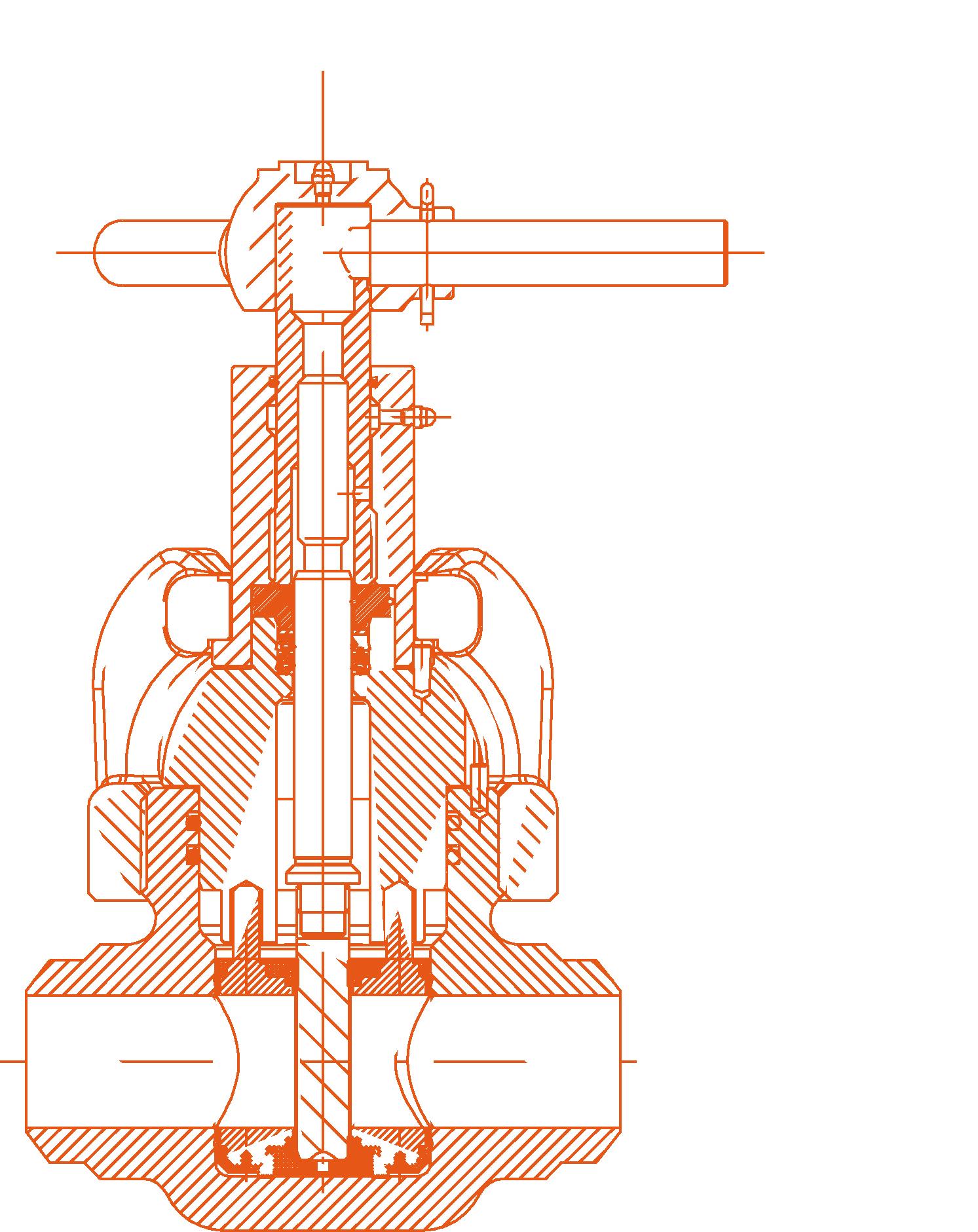
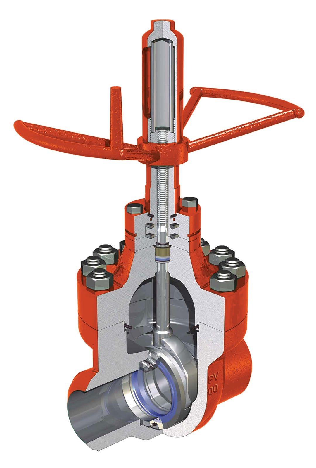
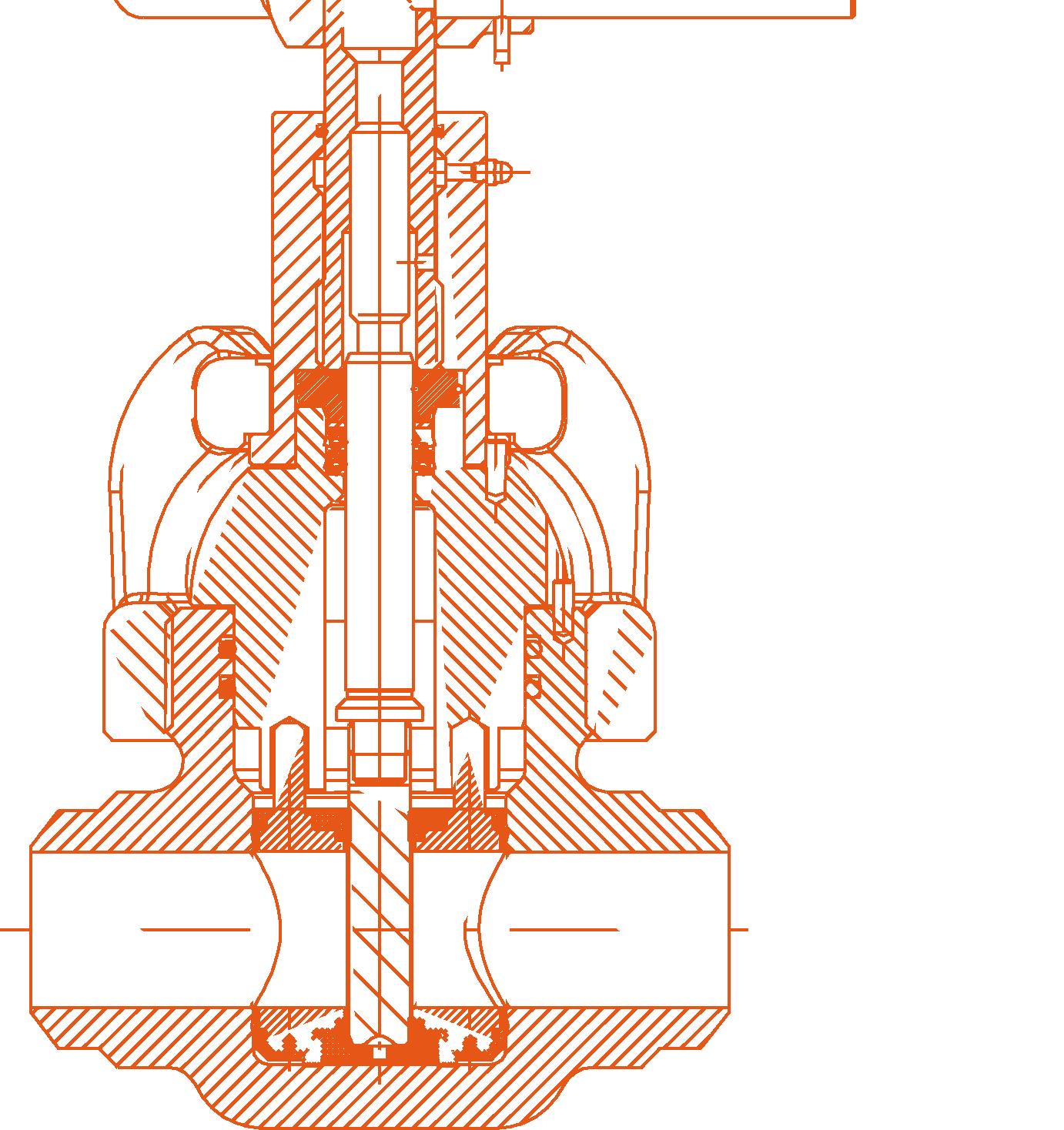
2.1 CONSTRUCTION
All the valves conform to API flange specifications in all pressure class ratings. The valves have rising stems that are driven by a double threaded hub for quick opening and closing with minimum turning effort. The permanently lubricated stems and stem screws are a fully sealed assembly, consisting of homogenous and fabric backed rings for high and low pressure.
2.2 APPLICATION FOR MUD GATE VALVES
Mud pumps lines and standpipe manifolds, oil and gas pipelines, sour gas and crude oil, corrosive water flood lines, cementing services, wellheads, well treating chemicals.
2.3 APPLICATIONS
• Drilling and well-treating chemicals
• Sour gas and crude oil
• Abrasive drilling mud
• Pipelines and manifolds
• Wellheads
• Water, oil and gas lines
• Cements and slurries
• Corrosive water flood lines
• Up to 5000 PSI and 204°C (400°F) services
Australian Pipeline Valve - Installation, Operation and Maintenance Manual 6 API6A MUD GATE VALVE - X-DM STYLE
2.4 SEAT ELASTOMERS
Buna N (nitrile) is the basic seat elastomer. It is excellent for petroleum oil and gases, fuelled oils and alcohols from -23°C to 93°C (-10°F to 200°F).
Hypalon is optionally offered compounded for maximum chemical resistance, particularly suited for oxidising acids, it resists hydrocarbon oils and fuels from -23°C to 121°C (-10°F to 250°F).
Viton is highly resistant to mineral acids and hydrocarbons and resists moderate concentrations of hydrogen sulphide. Serviceable from -23°C to 204°C (-10°F to 400°F) (not suitable for steam).
2.5 PRESSURE RATINGS OF VALVE
Valve rating must be selected to match the piping system in which the valve will be installed.
3.0 OPERATION
To open the valve: Rotate the handwheel counter-clockwise until the gate stops at the bonnet.
To close the valve: Rotate the handwheel clockwise until the gate stops at the bottom.
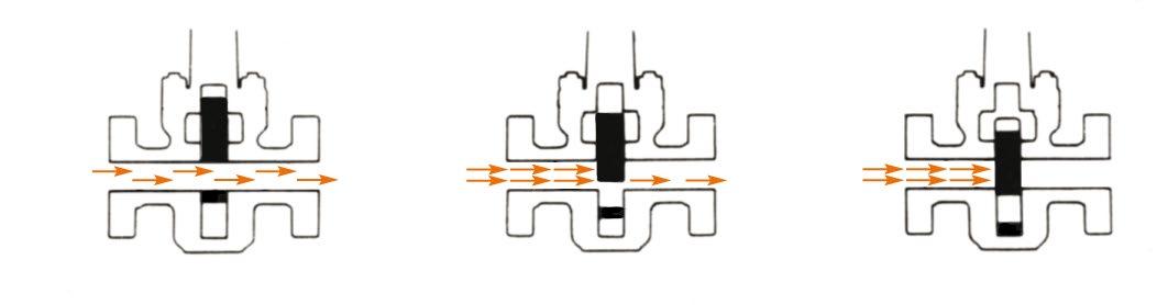
1. Only use full open or full closed. Never operate part open.
2. Turn the handle anti-clockwise to open the valve, and then turn the handle backwards by 1/4 - 1/2 turn.
3. Turn the handle clockwise to close the valve, and then turn the handle backwards by 1/4 - 1/2 turn.
Australian Pipeline Valve - Installation, Operation and Maintenance Manual 7 API6A MUD GATE VALVE - X-DM STYLE
CLASS 600 CLASS 900 CLASS 1500 1000 WP 2000 WP 3000 WP 5000 WP 7500 WP 1480 WP 2220 WP 3705 WP 1000 WP 2000 WP 3000 WP 5000 WP 7500 WP 2225 Test 3350 Test 5575 Test 2000 Test 4000 Test 6000 Test 7500 Test*11,250 Test *3" & below are tested to 10,000 psi, 4" & above 7500 psi except on special orders
API6A MUD GATE VALVE - X-DM STYLE
A gate valve should be either fully open or fully closed. Flow through a partially open valve may erode the gate and seat. The APV X-DM gate valve is designed to be opened or closed under full rated pressure differential but it will last longer if it is operated where there is little or no pressure in the line. The valve is opened by turning the handle counter-clockwise until a sharp increase in torque is felt. Further turning of the handle will damage the stem. The valve is closed by turning the handle clockwise. On all valves covered by this publication, either one of the following applies:
1) The handle moves down as the valve is being closed. The valve is fully closed when the handle stops down on the bonnet or housing. No further movement is possible.
2) The stem head engages a step in the inside of the bonnet when the valve is fully closed. Further turning of the handle will damage the stem. On these valves the stop of the stem will be flush with the top of the stem screw. This condition is visible through the stem protector cover.
Number of turns required to fully open or close valve:
4.0 MAINTENANCE OVERVIEW
Other than lightly lubricating the top stem area for anti corrosive purposes only, mud gates do not have lubrication or packing stick fittings like expanding/slab gate valves. Take note of the order that parts are removed in. Only experienced API6A valve repair professionals should attempt repairs.
4.1 GATE AND SEAT REPLACEMENT
Remove the valve from the line, vent the pressure in the valve cavity, remove the handle and top works and then remove the bonnet assembly. Be careful to protect the sealing surface between gate and seat rings during disassembling and removal. Clean the body cavity. Clean and check the gate seat and O-rings. In case any part is damaged replace parts. Replace gate & seat in same direction.
As X-DM valves are not lubricated, any slight scratching to sealing area on seat or gate will result in leakage. Very minor scratches can be polished out of the gate but do not machine or grind the gate as it is toleranced to the seat. Always replace all O-rings before reassembling valve.
4.2 STEM PACKING REPLACEMENT
If there is a leakage from the stem area, the packing should be checked. If there is any damage it should be replaced immediately.
Australian Pipeline Valve - Installation, Operation and Maintenance Manual 8
990 1480 2220 3705 1000 2000 3000 5000 1-1/2, 2x1-1/2 3.43.4 2, 3x2 4.04.0 4.24.2 10.1 10.110.1 2-1/2 5.15.1 5.15.1 9.29.2 3, 4x3 5.95.9 6.06.0 10.6 10.610.6 4, 5x4, 6x4 7.67.6 7.611.611.611.623.0 5, 6x5 14.8 29.729.7 6, 8x6 11.1 11.1 11.1 Rate working pressure as shown on the nameplate Valve Size
General Service (A)
Non Corrosive
General Service (B)
Slightly corrosive (Low CO2)
General Service (C)
Moderately to highly corrosive (High CO2)
Sour Service (D) Meets
Nace MR-0175 H2S
Sour Service (E) Slightly corrosive H2S (Low CO2)
Sour Service mod. (H) to highly corrosive (High CO2 + H2S)
Sour Service mod. to highly corrosive and chlorides (High H2S high CO2)
TRIM TYPES
to 30 BB
CC
to 30 EE
FF
HH
*Hydrogen sulphide partial pressure (in psi a) as defined by NACE MR - 01 - 75
**Partial pressure of carbon dioxide (in psi a).
Formula: Partial pressure (PP) = well pressure (psi) X percent of constituent in total well fluid X 1/100
Example: CO2 PP= 3000 psi X 4% x 1/100 = 120 psi*
Material must be chosen to resist CO2 weight loss corrosion.
4.3 ROUTINE MAINTENANCE
It’s important to keep the valve properly lubricated. A good #2 grade water resistant grease such as Chevron Ultra-Duty is recommended. Grease is applied to the Alemite fitting (either on the housing or the handle hub) with an automotive type grease gun. When greasing the fitting located on top of the handle hub the valve should be closed. This ensures the housing threads are adequately lubricated and prevents the grease leaking from the area between the handle and stem screw. Depending on the amount of use, the valve should be lubricated once a year at least.
Flushing should be performed at the first opportunity when the valve is exposed to frac sand, cement or drilling mud as these can set hard inside the valve and render it inoperable. Acidising fluids should also be cleaned out to prevent corrosion of internal parts which can result in leakage.
Application *H2S **CO2Fluid
Class
<0.05<7AA
<0.057
<0.05>30
<0.05<7DD
<0.057
<0.05>30
<0.05>30
Australian Pipeline Valve - Installation, Operation and Maintenance Manual 9 API6A MUD GATE VALVE - X-DM STYLE
API6A MUD GATE VALVE - X-DM STYLE
5.0 DISASSEMBLY, MINOR MAINTENACE & REASSEMBLY
Repairs mentioned in this I.O.M are limited to replacement of parts. For major repairs or extremely corroded or washed out bodies or bonnets, please contact an authorised APV repair facility.
5.1 TOOLS REQUIRED FOR MAINTENANCE & REPAIR
• 5/16” Nut driver
• Drill with #44 drill bit
• Grinder with flapper wheel
• Pressure test facility and fixtures
• Torque, impact or socket wrench and socket
• API adjustable pipe wrench
• Grease gun and grease, molybdenum disulfide base
• Hammer and mandrel or metal bar
• Screw driver
• Vice grips
5.2 DISASSEMBLY & MINOR MAINTENANCE 2” 2000, 3000 & 5000 WP
* Combination/type depending on size, rating, trim.
Also, refer Appendix 1 for Typical Bill of Materials.
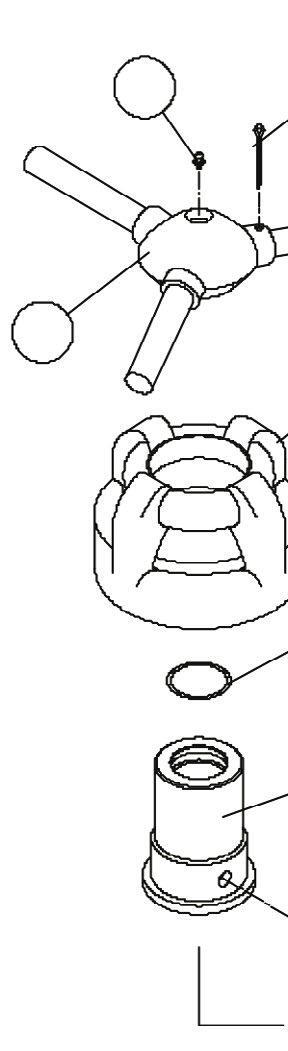
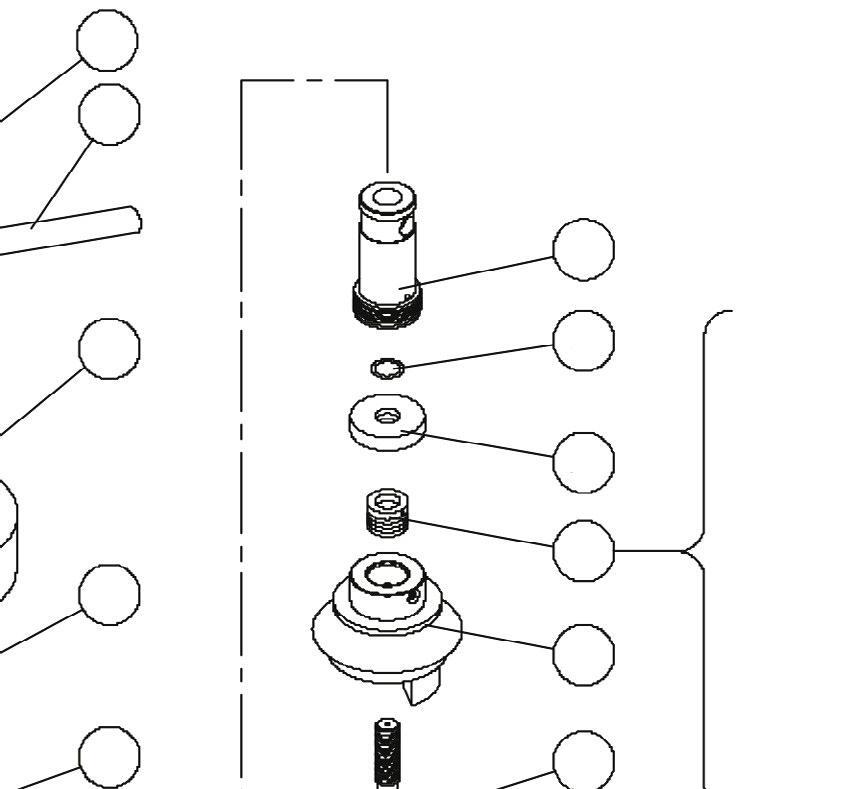
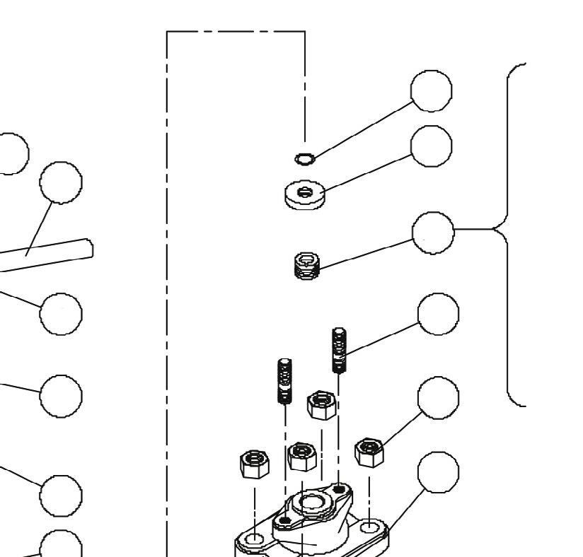
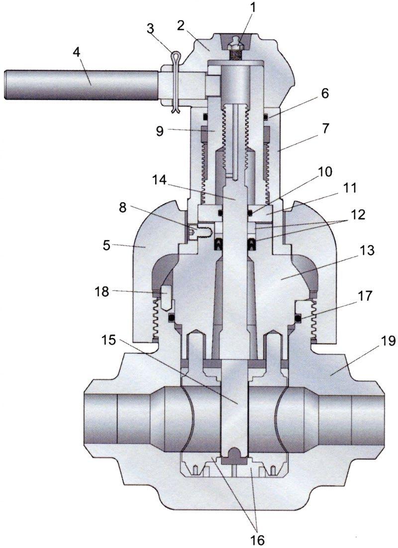
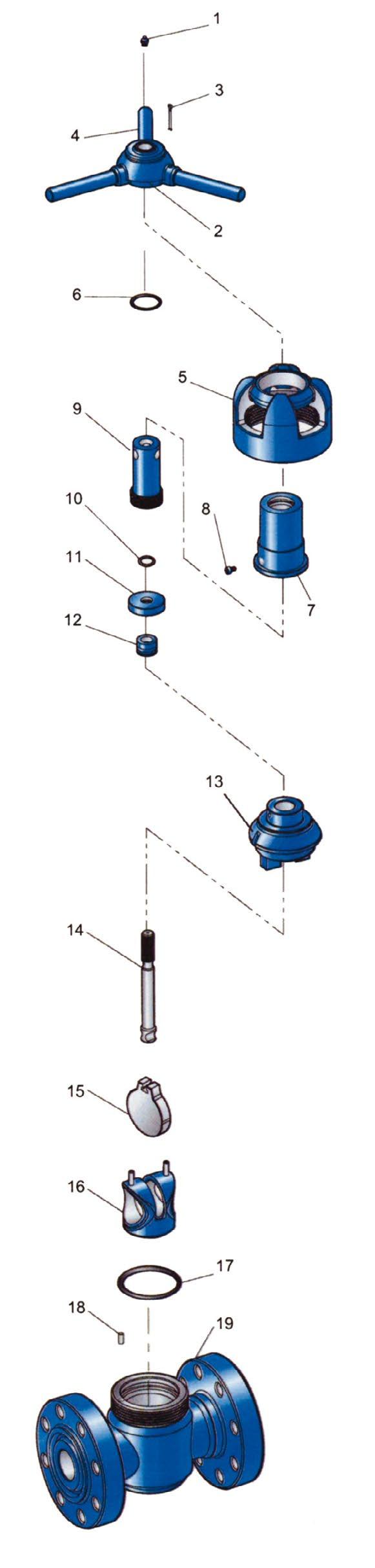
a. Fully open the gate valve. Unscrew coupling (5) and remove the bonnet assembly from the body. Collapse the seat (16) by pressing the top pins together and withdraw it from the body.
b. Whilst the bonnet assembly is on its side, remove pin (3) and lock handle (4), and lift off hub (2). Pull out coupling (5). Turn stem screw (9) clockwise to the bottom, then remove the gate (15) from the stem (14) by rotating it about a quarter turn to slide it off the tee-head of the stem.
c. At this time gate or seat replacement can be completed. Follow the applicable maintenance instructions then proceed to reassembly the valve using reassembly instruction 5.2.1. If further inspection is required for other parts, please see the following instructions.
Australian Pipeline Valve - Installation, Operation and Maintenance Manual 10
2 1 3 4 5 6 7 8 14 13* 12 11 10 9 15 16 17 18 19 BRONZE BUSHING FLAT TOP FOLLOWER HOMOGENEOUS RUBBER SEAL RING FABRIC REINFORCED SEAL RING FLAT BOTTOM ADAPTOR
d. To disengage the stem screw (9) from the stem turn it clockwise and remove it from under the bonnet. Unscrew the lock screw (8) and withdraw the screw housing (7) from the bonnet. Remove the retainer (11), O-ring seal (10) and stem seal assembly (12) from the bonnet. By turning the stem screw (9) clockwise you can them remove it from the screw housing. Withdraw the screw seal (6) from the housing and then bonnet seal (17) from the valve body.
e. Ensure all parts are cleaned thoroughly and check for any wear or damage. If any seals (6), (10), (17) or stem seal assembly (12) are cut or worn it is recommended they be replaced. Also check all sealing surfaces, they should be clean and free from debris, rust and scratches. This includes the area inside the body, next to the line bore where the seat fits, around the lower part of the bonnet that sits against the bonnet O-ring seal, the stem that travels through the packing and the bonnet stuffing box. These surfaces need to be clean (particular attention to the valve stem). Use an emery cloth to polish if required. Before reassembling, use a general purpose grease to lubricate all threads, seal rings, seat exterior, bonnet surfaces, stem and stem screws which are in contact with the seals.
5.2.1 Reassembly 2” 2000, 3000 & 5000 WP
1. Slide the threaded end of the stem (4) through the bonnet (13), from the underside and place the stem seal assembly (12) over the stem. This assembly consists of the seal rings, a flat-backed follower ring and a bushing, which are placed over the end of the stem in that order. Slide the retainer (11) with an O-ring seal (10) inside, over the stem. Observe that the lips of the rings do not get curled back. Seat the stem seal assembly into its counter bore in the bonnet.
2. Engage the stem screw (9) in the screw housing (7) about half its total travel and place the screw housing on the bonnet and stem.
3. Using vice grips, attach to tee head of stem, then rotate clockwise until stem is above lugs so the gate can be attached. Remove vice grips and attach gate to tee head. Rotate gate opening between the lugs. Place the assembly on its side with the lock set screw facing up and using the lock set screw as a marker, turn counter-clockwise three times at 360° each.
4. Install lock screw, tighten, and then install the seat onto the gate. Install the bonnet seal and index pin into the body. Grease the outside of the seat and the inside of the body. Install the bonnet assembly into the body. Install the coupling over the bonnet and tighten onto the body with a pipe wrench. Install the handle hub on the stems screw and insert the lock handle retainer lock with the lock handle pin. Do not spread the cotter pin at this time. Close the gate valve until the hub is resting on the top of the screw housing. At this point, mark the gate with pencil at the bottom of the seat bore. Raise the bottom of the gate by turning the handle counter-clockwise until half open. Measure the mark on the gate to verify the gate if fully down at 5/16” to 7/16”. If the distance is correct, then fully open the gate valve, spread the cotter and insert the drift bar pin. If correct, go to step 6.
5. If not correct, then remove the handle and coupling from bonnet assembly. Remove bonnet assembly. Remove bonnet assembly from the body. Remove the lock screw from the stem screw housing and adjust the timing by rotating the stem screw clockwise to increase distances or counter-clockwise to decrease distances. Repeat step 4.
6. When the X-DM mud gate vale is assembled in the manner described, the hub is stopped by the screw housing at the proper down position of the gate. By this design, over tightening is impossible and maximum sealing efficiency is assured.

Australian Pipeline Valve - Installation, Operation and Maintenance Manual 11 API6A MUD GATE VALVE - X-DM STYLE
7. Retest the valve as per API6A.
Note: see page 10, 16 & 17 for numbered illustrations as a guide. However, refer the as-built drawing supplied with valve as the design and parts vary slightly according to rating, trim, etc.
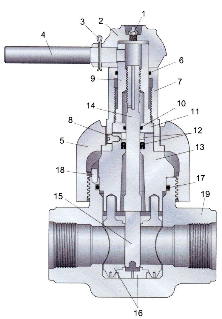
5.3 DISASSEMBLY & MINOR MAINTENANCE 3” & 4” 2000 & 3000 AND 3” & 5000 WP
* Combination/type depending on size, rating, trim.
Also, refer Appendix 1 for Typical Bill of Materials.
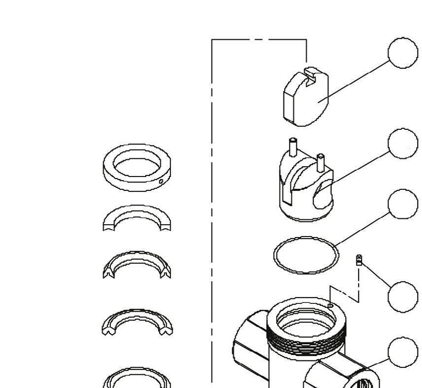
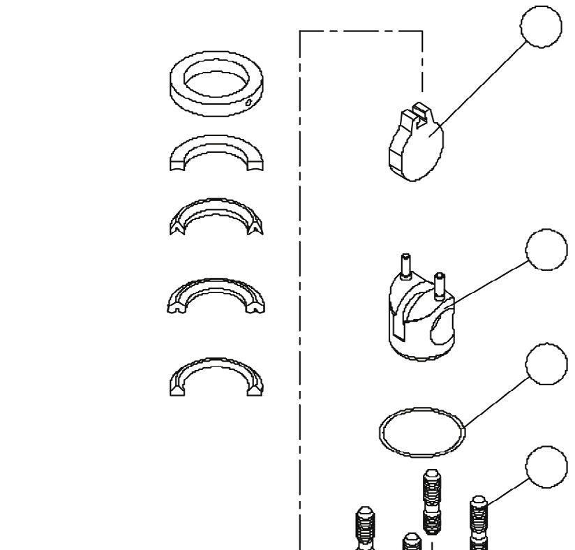
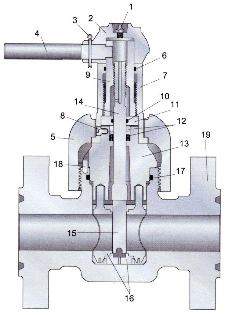
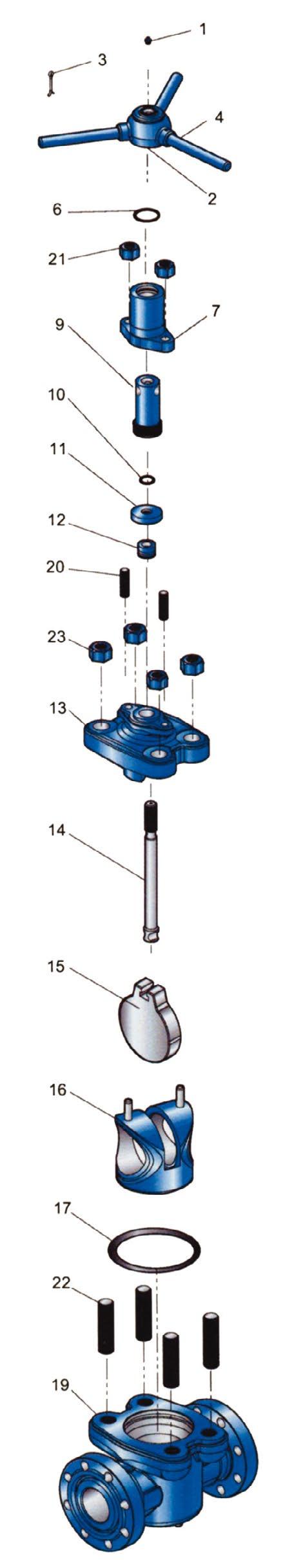
a. Fully open the gate valve. Withdraw nuts (23) and withdraw the bonnet assembly from the body. Fold the seat (16) by compressing the top pins together and withdraw it from the body.
b. Whilst the bonnet assembly is on its side, remove pin (3) and lock handle (4), and lift off hub (2). Turn stem screw (9) clockwise to the bottom, then remove the gate (15) from the stem (14) by rotating it about a quarter turn to slide it off the tee-head of the stem.
c. At this time gate or seat replacement can be completed. Follow the applicable maintenance instructions then proceed to reassembly the valve using reassembly instruction 5.3.1. If further inspection is required for other parts, please see the following instructions.
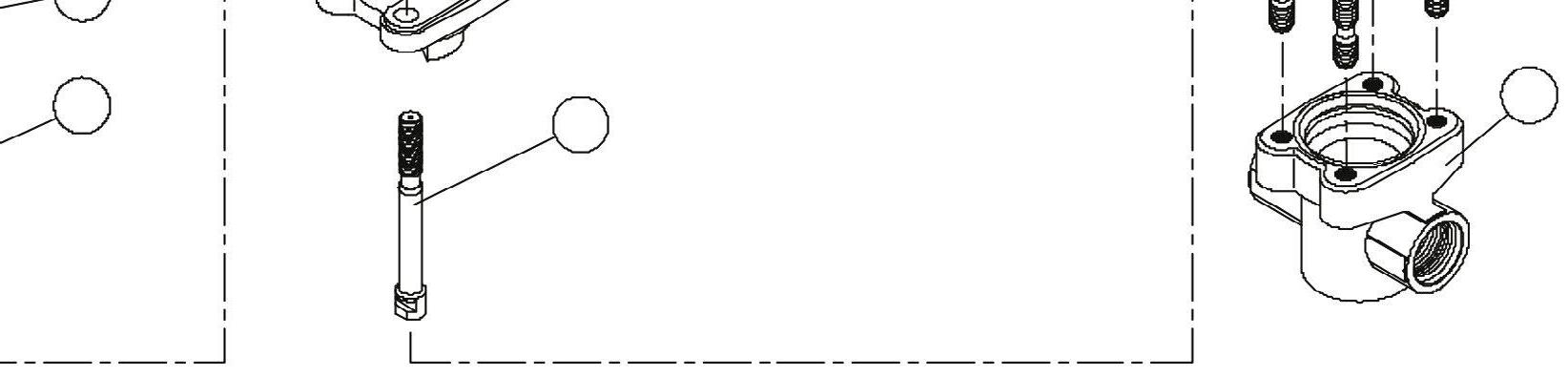
d. To disengage the stem screw (9) from the stem turn it clockwise and remove it from under the bonnet. Unscrew the nuts (21) (cap screws on 5” and 6x5”) and withdraw the screw housing (7) from the bonnet. Remove the retainer (11), O-ring seal (10) and stem seal assembly (12) from the bonnet. By turning the stem screw (9) clockwise you can them remove it from the screw housing. Withdraw the screw seal (6) from the housing and then bonnet seal (17) from the valve body.
e. Ensure all parts are cleaned thoroughly and check for any wear or damage. If any seals (6), (10), (17) or stem seal assembly (12) are cut or worn it is recommended they be replaced. Also check all sealing surfaces, they should be clean and free from debris, rust and scratches. This includes the area inside
Australian Pipeline Valve - Installation, Operation and Maintenance Manual 12 API6A MUD GATE VALVE - X-DM STYLE 2 1 3 4 21 6 7 9 13 12* 23 11 10 20 15 16 17 22 19 BRONZE BUSHING FLAT TOP FOLLOWER HOMOGENEOUS RUBBER SEAL RING FABRIC REINFORCED SEAL RING FLAT BOTTOM ADAPTOR 14
the body, next to the line bore where the seat fits, around the lower part of the bonnet that sits against the bonnet O-ring seal, the stem that travels through the packing and the bonnet stuffing box. These surfaces need to be clean (particular attention to the valve stem). Use an emery cloth to polish if required. Before reassembling, use a general purpose grease to lubricate all threads, seal rings, seat exterior, bonnet surfaces, stem and stem screws which are in contact with the seals.
5.3.1 Reassembly 3” & 4” 2000 & 3000 and 3” 5000 WP
1. Slide the threaded end of the stem (14) through the bonnet bore from the underside and place the stem seal assembly (12) over the stem. This assembly consists of the seal rings, a flat-backed follower ring and a bushing, which are placed over the end of the stem in that order. Slide the retainer (11) with an O-ring seal (10) inside, over the stem. Observe that the lips of the rings do not get curled back. Seat the stem seal assembly into its counter bore in the bonnet. Install the bonnet studs (20).
2. Engage the stem screw (9) in the screw housing (7) about half its total travel and place the screw housing on the bonnet and stem. Replace nuts (21).
3. Rotate the stem screw clockwise until it bottoms on the retainer, the back it up approximately 1/8 of a turn. Engage the gate (15) on the tee head of the stem and turn them together counter clockwise until the gate touches the underside of the bonnet lugs. Align the gate with the opening between the lugs and retract it into the bonnet by turning the stem screw counter clockwise. Place the hub (2) on the stem screw, insert the lock handle (4), and retain it with the lock handle pin (3).
Assembly and timing procedure for 3” & 4” 2000 & 3000 and 3” 5000 WP
4. Install the seat (16) onto the gate and grease the outside of the seat. Install the body studs and bonnet seal, then grease the inside of the body. Install the bonnet assembly into the body. Replace body nut and tighten per appropriate torque. Close the gate fully by turning the handle clockwise. Make sure the hub sits flush on the screw housing. Also, make pencil marks on the gate even with the bottom of the seat bore. Open the gate by turning the handle counter-clockwise and measure distance from mark to the bottom of the gate. This distance should fall within following limits for each valves size:
If either the distance is off, or the hub is not flush with the screw housing, open the gate fully, loosen the bonnet nut and remove. Turn the handle clockwise while raising the stem screw assembly above the bonnet studs. Turn the screw assembly clockwise or counter-clockwise, as appropriate to correct timing. Turn the handle counter clockwise to lower the stem screw assemble back down on the retainer. Replace the nuts and hand tighten. Check aforementioned timing criteria. If still not timed, repeat timing process. If timing is correct, tighten the bonnet nuts to appropriate torques as per table & diagram on page 14.
5. When the X-DM gate valve is assembled in the manner described, the hub is stopped by the screw housing at the proper down position of the gate.
6. Retest the valve as per API6A.
Note: see pages 12 & 18 for numbered illustrations as a guide. However, refer the as-built drawing supplied with valve as the design and parts vary slightly according to rating, trim, etc. For 4” & 5” 3000, 5000 consult the as-built drawing as the configuration is slightly different.
Australian Pipeline Valve - Installation, Operation and Maintenance Manual 13 API6A MUD GATE VALVE - X-DM STYLE
3” 4”
- 1/2”
- 9/16”
3/8”
7/16”
API6A MUD GATE VALVE - X-DM STYLE
GLAND PACKING TORQUE In Lb (Nm)
TORQUE VALUE
1/2” (13) 60 (7)
5/8” (16) 89 (10)
3/4” (19) 107 (12)
7/8” (22) 162 (18)
1” (25) 244 (27)
1 1/8” (29) 322 (36)
1 1/4” (32) 410 (46)
1 3/8” (35) 510 (58)
STUD LUBRICATION
BOLT TIGHTENING SEQUENCE
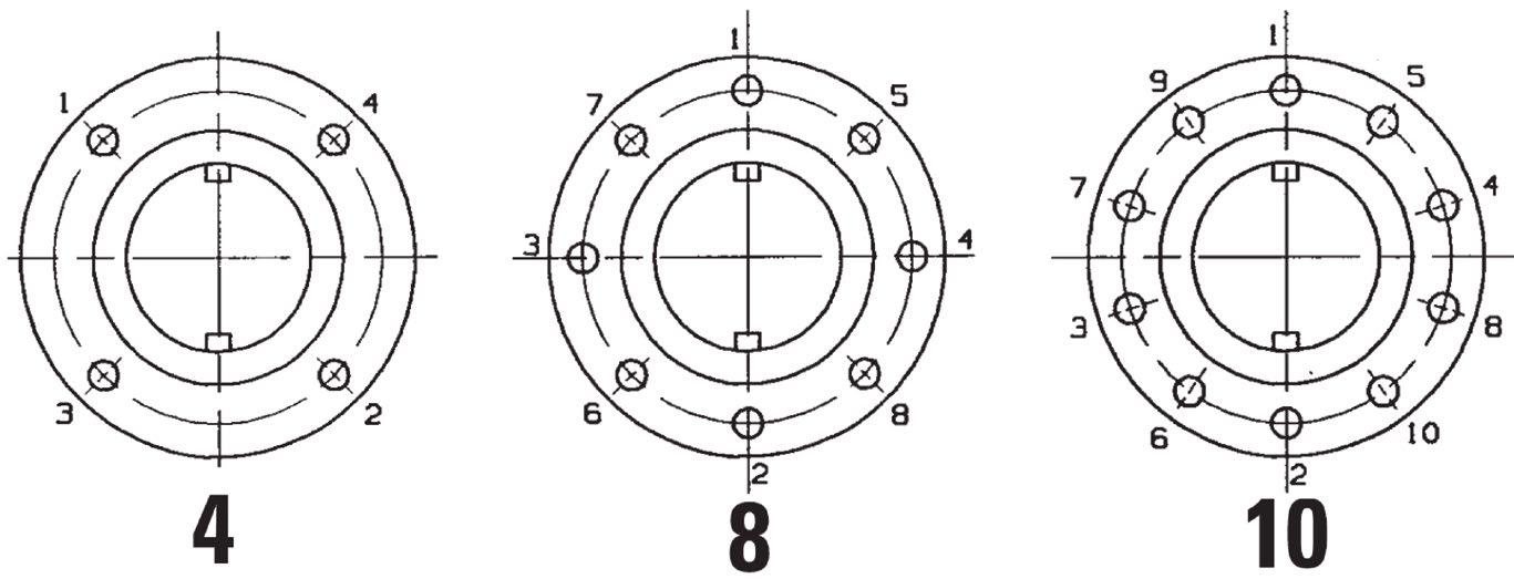
• Re-tightening of body bolts (with system de-pressurised) and gland packing bolting is permissible, if leakage occurs in these areas.
• Required Torque values are given in tables shown above.
• The use of copper-based Anti-seize grease for body and packing stud lubrication and molybdenum disulfide anti-seize grease for stem packing lubrication is recommended.
• Bolt tension should be decreased by 25% from values shown in the table above when other or no lubrication is used.
Australian Pipeline Valve - Installation, Operation and Maintenance Manual 14
DIAMETER in (mm)
STUD
in/lb (Nm)
6.0 TROUBLESHOOTING
TROUBLE PROBABLE CAUSE REMEDY
Will not open or closeRestriction in body cavity
Accumulation of mud, sand or other foreign matter in valve body
Hard to operate
Restricted bore in valve
Erratic Operation
Leaking bonnet flange
Leaking around stem
Will not seal downstream
Stem thread damage
Work handwheel back and forth. If ice is suspected, see procedure below
Pull apart & clean
Repair or replace
Gate or seat mechanism damaged Replace
Gate not properly aligned with the bore of seats
Stem threads damaged
Seat damaged
Loose bonnet connection
Damaged bonnet seal ring
Packing and/or stem damaged
Worn or damaged gate and seats
Dirt on gate/seat area
Pull apart and remedy
Back up from hard operating spot before continuing in one direction. Replace at first opportunity
Replace
Isolate from pressure, bleed down cavity and tighten bonnet
Replace seal ring
Replace packing or stem
Replace seat and/or gate first opportunity
Pull apart and clean
Australian Pipeline Valve - Installation, Operation and Maintenance Manual 15 API6A MUD GATE VALVE - X-DM STYLE
APPENDIX 1
Bill Of Material
2” - 2000, 3000 & 5000 WP
Australian Pipeline Valve - Installation, Operation and Maintenance Manual 16
MUD GATE VALVE - X-DM STYLE
API6A
Butt Weld End
Screwed End
RTJ Flanged
Australian Pipeline Valve - Installation, Operation and Maintenance Manual 17 API6A MUD GATE VALVE - X-DM STYLE Item No. Description 1 Lube Fitting 2 Hub Assembly 3 Pin, Lock Handle 4 Lock Handle 5 Coupling 6 Stem Screw Seal 70 D Buna-N 75 D Viton 7 Screw Housing 8 Lock Screw 9 Stem Screw 10 Secondar y Seal 90 D Buna-N 90 D Viton 11 Retainer 12 Stem Seal Assembly (includes bronze bushing) 90 D Buna-N 90 D Viton 13 Bonnet (A487 Steel) 14 Stem 15 Gate 16 Seat Steel 90 D Buna-N Seat 316SS or 410SS 70 D Buna-N 90 D Viton 17 Bonnet Seal 90 D Buna-N 90 D Viton 18 Index Pin 19 Body Screwed End LP (NPT) EUE Flanged End RTJ Weld End Sch 80 Sch XXH Sch 160 Steel Steel Steel Steel Steel Steel Steel 316SS or 410SS WCB Steel 4130 1029 316SS or 410SS Steel Steel Example only, parts and materials can vary according to specified trim, pressure and model variations. Refer to as-built drawing for each pressure class.
(CONTINUED) Bill Of Material 2” - 2000, 3000 & 5000 WP
APPENDIX 1
3” - 3000 & 5000 and 4” 3000* WP
* For 4” 3000 and 5000 consult as-built drawing as design is slightly different.
Example only, parts and materials can vary according to specified trim, pressure and model variations. Refer to as-built drawing for each pressure class.
Australian Pipeline Valve - Installation, Operation and Maintenance Manual 18 API6A MUD GATE VALVE - X-DM STYLE
APPENDIX 1 (CONTINUED) Bill Of Material
Item No. Description 1 Lube Fitting 2 Hub Assembly 3 Pin, Lock Handle 4 Lock Handle 6 Stem Screw Seal Buna-N Viton 7 Screw Housing 9 Stem Screw 10 Secondar y Seal Buna-N Viton 11 Retainer 12 Stem Seal Assembly (includes bronze bushing) 90 D Viton 13 Bonnet 14 Stem 15 Gate 16 Seat Steel 70 D Buna-N Seat 316SS or 410SS 70 D Buna-N 90 D Viton 17 Bonnet Seal Buna-N Viton 19 Body Screwed End LP (NPT) NUE EUE Flanged End RTJ Weld End Sch 80 Sch XXH Sch 160 20 Bonnet Stud (2) A-320-L7 or B7 Each 21 Bonnet Stud Nut (2) A-320-L7 or 2H Each 22 Body Stud (4 Required) A-320-L7 or B7 Each 23 Body Stud Nut (4) A-320-L7 or 2H Each Steel Steel Steel Steel Steel Steel Steel A-487 Steel 316SS or 410SS 316SS or 410SS
APPENDIX 2
API6A MATERIAL SERVICE CATEGORIES & RATING LEVELS
Overview Standards
Australian Pipeline Valve (APV) standards comply with technical specification API-6A. The description for APV valves consist of a general description, working pressure, temperature rating, material class rating, product specification level (PSL) and performance requirement (PR). These ratings are defined in the following API-6A tables.
To comply with API-6A, APV offers:
Pressure ratings in psi: 2000, 3000, 5000, 10,000 & 15,000. Temperature ratings: L, P, R, S, T, U, V, X & Y.
Material class: AA, BB, CC, DD, EE, FF & HH.
Product specification level: 1, 2, 3 & 4 (PSL 1, 2, 3, 4)
Performance requirement: 1 & 2.
Australian Pipeline Valve - Installation, Operation and Maintenance Manual 19 API6A MUD GATE VALVE - X-DM STYLE
*See paragraph A5 of API-6A 17a. Ed.
Australian Pipeline Valve - Installation, Operation and Maintenance Manual 20 API6A MUD GATE VALVE - X-DM STYLE APPENDIX 2 (CONTINUED) RECOMMENDED MINIMUM PSL FOR PRIMARY PARTS API MATERIAL REQUIREMENTS
PR1 is standard PR2
times
required) NACE No YesYes YesNoYes High H2S Concentrate No No YesNoNoYes Close Proximity*NoNoNoYes YesYes Rated Working Pressure, PSI PSL PSL PSL PSL PSL PSL 5,000 1 12213 10,000 2 23334 15,000 and up 3 34444 MATERIAL CLASS BODY, BONNET & FLANGE AA - General Service Carbon or low allow steel Carbon or low allow steel BB - General Service Carbon or low allow steel Stainless Steel CC - General Service Stainless Steel Stainless Steel DD - Sour Service Carbon or low allow steel Carbon or low allow steel EE - Sour Service Carbon or low allow steel Stainless Steel FF - Sour Service Stainless Steel Stainless Steel HH - Sour Service CRAs CRAs MINIMUM MATERIAL REQUIREMENTS PRESSURE CONTROLLING PARTS As per API6A (ISO 10423) 2013: As defined by ISO 15156 (all parts) (NACE MR0175) (See API6A) In compliance with ISO 15156 (all parts) (NACE MR0175) (see API6A) CRA required on retained fluid-wetted surfaces only; CRA cladding of low-alloy or stainless steel is permitted (See API6A) CRA as defined in API6A; ISO 15156 (all parts) (NACE MR0175; see API6A) definition of CRA does not apply a a a a b b b bcd b b b bcd a b c d
also available (increased cycle
on test
APPENDIX 2 (CONTINUED)
PSL (PRODUCT SPECIFICATION LEVEL) MATERIAL REQUIREMENTS
PSL Material Control is found in API Specification 6A, Specification for Wellhead and Christmas Tree Equipment
PSL (PRODUCT SPECIFICATION LEVEL) QUALITY CONTROL
PSL Material Control is found in API Specification 6A, Specification for Wellhead and Christmas Tree Equipment
400
PSL (PERFORMANCE REQUIREMENTS) LEVELS
There are two Performance Requirement Levels, PR1 and PR2. The latter represents more rigorous performance requirements. See API Specification 6A, Section 300 and Section 900.
Section 905 covers valves (905.3 - Flowline Valves, 9.5.5 - Actuated Valves).
Australian Pipeline Valve - Installation, Operation and Maintenance Manual 21 API6A MUD GATE VALVE - X-DM STYLE
TEMPERATURE
API PRESSURE/TEMPERATURE RATINGS (Y)* Fº Cº MIN. MAX.MIN. MAX. K-75 to 180-60 to 82 L-50 to 180-46 to 82 P-20 to 180-29 to 82 R* S0 to 140-18 to 60 T0 to 180-18 to 82 U V 0 35 to to 250 250 -18 2 to to 121 121 TEMPERATURE CLASSIFICATION OPERATING RANGE Room Temperature* X* 0to350 -18to177 to 343 Y* 0to650 -18 * No longer referenced in API6A/ISO 10423-2013 N-50 to 140-46 to 60 0 to 250 300350 400 450 500 550 600 650 2000 1955 1905 1860 1810 1735 1635 1540 1430 3000 2930 2860 2785 2715 2605 2455 2310 2145 5000 4880 4765 4645 4525 4340 4090 3850 3575 Rated Working Pressure PSI TEMPERATURE IN ºF * Based on ‘Y’ Temp. Due to elastomers, Gate Valves are temp ‘T’ or ‘U’ as standard hence consult seperate chart.
API
REQUIREMENTS
Section
Section 400
APPENDIX 2 (CONTINUED)
API6A TRIM TYPES
TRIM CODE
T-21
STANDARD TRIM
T-22
T-23
T-24
S-24
T-26
T-27
T-36
T-37
TRIM TYPE
For essentially non corrosive liquids or gases. Typical are crude and reined oils, natural or refined gases and processed hydrocarbons. Typical uses are wellheads, manifolds flowlines, and other similar installations requiring a through conduit valve. The temperature limitations are 0º to 250ºF (-17.7ºC to 121ºC)
STAINLESS TRIM
For substantially the same service as T-21 but where the corrosion resistance of 13% Chrome Stainless Steel internal parts are desirable. Also usable for mildly corrosive fluids and gases where limited corrosion of the internal body surfaces can be tolerated. The temperature limitations are 0º to 250ºF (-17ºC to 121ºC). Recommended when partial pressure of CO2 is greater than 7.3.
FULL STAINLESS STEEL TRIM
For any liquid or gaseous product for which the resistance of the 13% Chrome Stainless is adequate. Also used where the resistance of Stainless Steel is desirable from the standpoint of product purity. The temperature limitations are 0º to 250ºF (-17.7ºC to 121ºC).
Recommended when partial pressure of CO2 is greater than 30.
SOUR GAS & OIL
Primarily for sour gas and oil where resistance to Hydrogen Sulfide embrittlement is required. Also suitable for other chemicals, products or hydrocarbons when H2S is present. May be used when CO2 is present in smaller amount then H2S. The temperature limitations are 0º to 250ºF (-17.7ºC to 121ºC)
STAINLESS SOUR GAS AND OIL TRIM
Primarily for sour gas and oil when the CO2 exceeds the H2S content. It is intended to provide resistance to the metal loss type of corrosion usually associated with CO2, plus resistance to Hydrogen Sulphide embrittlement. The temperature limitations are 0º to 250ºF (-17.7ºC to 121ºC)
WATERFLOW (UNINHIBITED)
Primarily for use in untreated or uninhibited brackish saline water typically associated with oilfield waterflood projects and/or disposal wells in which the internal plastic coating of the body surfaces provides resistance to salt water corrosion. The internal parts are also resistant to Sulfide embrittlement and corrosion. The temperature limitation are 0º to 250ºF (-17.7ºC to 121ºC)
LOW TEMPERATURE – STANDARD TRIM – GENERAL OILFIELD
For essentially non-corrosive liquids or gases. Typical examples are crude and refined oils, natural or refined gases and processed hydrocarbons. Typical uses are wellheads, manifolds, flowlines and other similar installations requiring a through conduit valve. The temperature limitations are -50º to 180ºF. (-45ºC to 82ºC)
LOW TEMPERATURE – SOUR GAS AND OIL
Primarily for sour gas and oil where resistance to Hydrogen Sulphide embrittlement is required. Also suitable for other chemicals, products or hydrocarbons where H2S is present. May be used when CO2 is present in smaller amounts than H2S. The temperature liitations are -50ºC to 180º F (-45ºC to 82ºC)
SPECIAL TRIMS AND TEMPERATURE RANGES AVAILABLE UPON REQUEST
Australian Pipeline Valve - Installation, Operation and Maintenance Manual 22 API6A MUD GATE VALVE - X-DM STYLE
S-37 API SPEC, 6A RETAINED FLUID RATING AA BB CC DD EE FF AA DD EE
APPENDIX 2 (CONTINUED)
VALVE TRIM CHART FOR API6A GATE VALVES
1
5
This
Australian Pipeline Valve - Installation, Operation and Maintenance Manual 23 API6A MUD GATE VALVE - X-DM STYLE
BODY & BONNET BONNET SEAL GATE SEAT STEM TRIM SERVICE MATERIALS Waterflood T27 EE 2,000 3,000 5,000 API 60K Alloy Steel w/Plastic Coat SS 17-4PH PRESSURE RATING PSI API MATERIAL CLASS 316 410 410 316 410 316 17-4PH General Moderately Corrosive CO2 T22BB Carbon or Low Allow Steel SS 2,000 3,000 5,000 General Oilfield Gas, Oil T21AA Carbon or Low Allow Steel CS 2,000 3,000 5,000 410 410 17-4PH 410 410 410 17-4PH w/MDC5 SS Sour (H2S) Service NACE4 MR01-75 T24 DD API 60K Alloy Steel SS 2,000 3,000 5,000 General Moderately Corrosive CO2 T23CC API 60K CA6NM Stainless Steel Sour (H2S) Service NACE4 MR01-75 S24 EE API 60K Alloy Steel SS 410 17-4PH w/MDC5 2,000 3,000 5,000 4130 17-4PH w/MDC5 4130 or 17-4PH Nitrided 2,000 3,000 5,000 4130 or 17-4PH Nitrided SS 4130 4130 17-4PH w/MDC5 17-4PH 17-4PH 17-4PH w/MDC5 17-4PH w/MDC5 CS API 6A TEMPERATURE CLASS L: SERVICE -50ºF TO 180ºF (-46ºC TO 82ºC) 2,000 3,000 5,000 API 60K Alloy Steel Corrosive (CO2) & Sour (H2S) NACE4 MR01-75 T26FF 2,000 3,000 5,000 API 60K CA6NM Stainless Steel General Oilfield Gas, Oil T36AA 2,000 3,000 5,000 API 60K Alloy Steel 17-4PH w/MDC5 Sour (H2S) Service NACE4 MR01-75 S37 EE 2,000 3,000 5,000 API 60K Alloy Steel SS 17-4PH 4130 17-4PH w/MDC5 SS 4130 4130 Sour (H2S) Service NACE4 MR01-75 T37 DD
QPQ NITRIDE
CHARPY V NOTCH IMPACT TEST
4
MDC MOLYBDENUM DISULFIDE COATING
list
provided as a guide only Australian Pipeline Valve reserves the right to provide alternate materials without prior notice. API6A TEMPERATURE CLASS P: SERVICE -20°F TO 180°F (-29°C TO 82°C) 316
is
Australian Pipeline Valve - Installation, Operation and Maintenance Manual 25 NOTES

© Copyright Australian Pipeline Valve 1990 - 2024 Edition
Catalogues, photos, brochures and technical publications are the exclusive property of Australian Pipeline Valve. Any unauthorised reproduction in total or in part, shall result in prosecution. Products and data sheets in this publication are subject to change at anytime without notice. Australian Pipeline Valve reserves the right to carry out amendments to products and materials.
Australian Pipeline Valve - Installation, Operation and Maintenance Manual 25
NOTES

www.australianpipelinevalve.com.au AUSTRALIAN PIPELINE VALVE® HEAD OFFICE 70-78 Stanbel Road Salisbury Plain South Australia 5109 Telephone +61 (0)8 8285 0033 email: admin@australianpipelinevalve.com.au If you have any requirements in the field of valves, please contact us for a prompt response. Continuous development of Australian Pipeline Valve products may necessitate changes in the design or manufacture process. Australian Pipeline Valve reserves the right to effect any such changes without prior notice. © Australian Pipeline Valve 1990 - 2024 Edition LOCAL DISTRIBUTOR/AGENT IOM APV Mud Gate
