
www.australianpipelinevalve.com.au INSTALLATION, OPERATION & MAINTENANCE MANUAL GLOBE VALVES OS & Y API623/BS1873/B16.34
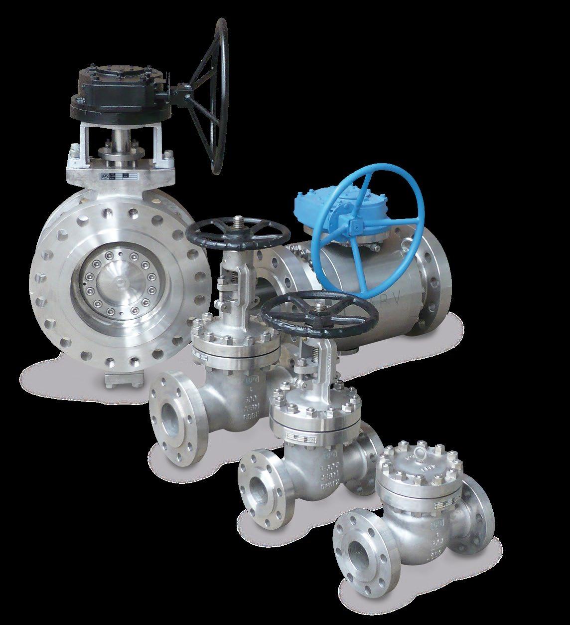
COMPLETE PRODUCT LINE
“Australian Pipeline Valve produces isolation, control and flow reversal protection products for severe and critical service media in utility, steam, pipelines, oil & gas and process industries. APV valves and pipeline products form the most competitive portfolio in the market.”

View our catalogues at www.australianpipelinevalve.com.au AUSTRALIAN PIPELINE VALVE BRAND RANGE - CATALOGUES APV FAMILY OF BRANDS RANGE - CATALOGUES
Oilfield Products Valves & Wellheads Gate, Globe & Check Valves - Forged Steel Plug Valves Lubricated, Sleeved & Lined Gate, Globe & Check Valves - Cast Steel Diamond Gear Gearboxes Flowturn Gate, Globe & Check Valves Flowturn Instrument Valves Flowturn Ball Valves Multiway & Deadman Flowturn Strainers & Sight Glasses Supercheck Wafer Check Valves Superseal Butterfly Valves Steamco Steam Valves Superseal Industrial Ball Valves TwinLok Tube Fittings Uniflo Check Valves Torqturn Actuators Ball Valves Floating & Trunnion Mounted Ball Valves Floating Small Bore Ball Valves Special Service Product Brochure Contact us for your local stockist/distributor
GLOBE VALVES OS & Y - API623/BS1873/B16.34 Australian Pipeline Valve - Installation, Operation and Maintenance Manual 1 Introduction 3 Safety Information 4-5 Valve Identification 6 1.0 Installation 7-9 1.1 Installation positions 7 1.2 Preparation for installation 7 1.3 End connections 8 1.4 Post-installation procedures 9 2.0 Operation 9-12 2.1 Common disc styles 10 2.2 Applications of different disc types 10-11 3.0 Maintenance 12-14 3.1 Gland packing replacement 12-14 3.2 Repairs 14 4.0 Maintenance Procedures 15-16 4.1 Preventative maintenance and periodic inspections 15-16 5.0 Extraordinary Maintenance or Replacement/Repair of Damaged Parts 16-22 5.1 Stem 16 5.2 Gland disassembly & replacement of stem packing 17-18 5.3 Bonnet disassembly & stem replacement 18-20 5.4 Valve reassembly 20-21 5.5 Disassembly of yoke nut 21 5.6 Disc and seat repair 21-22 INDEX

GLOBE VALVES OS & Y - API623/BS1873/B16.34 Australian Pipeline Valve - Installation, Operation and Maintenance Manual 2 5.7 Disc and seat re-lapping/machinig 22 6.0 Reassembly 22-24 Appendix A - Body/bonnet bolting torque 25-29 Appendix B - Exploded B.O.M. 30-32 Appendix C - Figure Number System 33-34 Appendix D - Working pressure & test matrix 35 Warranty 36 © Copyright Australian Pipeline Valve 1990 - 2024 Edition Catalogues, photos, brochures and technical publications are the exclusive property of Australian Pipeline Valve. Any unauthorised reproduction in total or in part, shall result in prosecution. Products and data sheets in this publication are subject to change at anytime without notice. Australian Pipeline Valve reserves the right to carry out amendments to products and materials.
INTRODUCTION
The majority of this information is common knowledge to experienced valve users. When properly installed in applications for which they were designed, Australian Pipeline Valve (APV) valves will give long reliable service. This instruction is only a guide for installation and operation on standard service and covers general maintenance and minor repairs. A professional APV approved valve engineering facility should be utilised for reconditioning or major repairs.
We recommend that this entire document be read prior to proceeding with any installation or repair. Australian Pipeline Valve and it’s parent company take no responsibility for damage or injury to people, property or equipment. It is the sole responsibility of the user to ensure only specially trained valve repair experts perform repairs under the supervision of a qualified supervisor.
RESPONSIBILITY FOR VALVE APPLICATION
The User is responsible for ordering the correct valves. The user is responsible for ensuring APV Valves are selected and installed in conformance with the current pressure rating and design temperature requirements. Prior to installation, the valves and nameplates should be checked for proper identification to ensure the valve is of the proper type, material and is of a suitable pressure class and temperature rating to satisfy the requirements of the service application.
Do not use any valve in applications where either the pressure or temperature is higher than the allowable working values. Also valves should not be used in service media if not compatible with the valve material of construction, as this will cause chemical attacks, leakage, valve failure.
RECEIVING INSPECTION AND HANDLING
Valves should be inspected upon receipt to ensure:
- Conformance with all purchase order requirements.
- Correct type, pressure class, size, body and trim materials and end connections.
- Any damage caused during shipping and handling to end connections, hand wheel or stem.
The User is advised that specifying an incorrect valve for the application may result in injuries or property damage. Selecting the correct valve type, rating, material and connections, in conformance with the required performance requirements is important for proper application and is the sole responsibility of the user.
GLOBE VALVES OS & Y - API623/BS1873/B16.34 Australian Pipeline Valve - Installation, Operation and Maintenance Manual 3
Note
SAFETY INFORMATION
The following general safety information should be taken in account in addition to the specific warnings and cautions specified in this manual. They are recommended precautions that must be understood and applied during operation and maintenance of the equipment covered in this I.O.M.
To avoid injury, never attempt disassembly while there are pressures either upstream or downstream. Even when replacing stem packing, caution is necessary to avoid possible injury. Disassemble with caution in case all pressures are not relieved.
To prevent valve bending, damage, inefficient operation, or early maintenance problems, support piping on each side of the valve. Warning, certain gases and fluids could cause damage to human health, the environment or property hence the necessary safety precautions to prevent risk should be taken.
• A valve is a pressurised mechanism containing fluids under pressure and consequently should be handled with appropriate care.
• Valve surface temperature may be dangerously too hot or too cold for skin contact.
• Upon disassembly, attention should be paid to the possibility of releasing dangerous and or ignitable accumulated fluids.
• Ensure adequate ventilation is available for service.
At no time shall any weld repair be conducted on the valve while in service. Never strike the valve with a hammer or other impact device. Ensure that no excess weight is placed on the valve that was not part of the original manufacture design.
This manual provides instructions for storing, general servicing, installation and removal of globe valves. APV and it’s resellers refuse any liability for damage to people, property or plant as well as loss of production and loss of income under any circumstances but especially if caused by: Incorrect installation or utilisation of the valve or if the valve installed is not fit for intended purpose. It is the sole responsibility of the user to ensure the valve type and materials are correctly specified.
GLOBE VALVES OS & Y - API623/BS1873/B16.34 Australian Pipeline Valve - Installation, Operation and Maintenance Manual 4
DURING OPERATION TAKE INTO ACCOUNT THE FOLLOWING WARNINGS:
a- Graphite/Graphoil packing and body gaskets are very brittle, any impacting, twisting or bending should be avoided.
b- The valve’s internal parts such as disc, stem, seats, seals, gaskets shall be handled with care avoiding scratches or surface damage.
c- All tools and equipment for handling the internal parts shall be soft coated or else take extreme care, especially on machined mating surfaces and with soft parts.
d- Valves can be fitted with gaskets or seals in PTFE, Buna, Viton, etc., hence high temperatures will damage sealing components.
e- Globe valves can be used to throttle for short periods (on clean service only) but only if at least 25% open or else venturi action will damage seating area, body.
For all operations make reference to position number on part list of the applicable drawing listed.
Packing leakage could result in personal injury. Valve packing is tightened prior to shipping but may require readjustments to meet specific service conditions.
Personal injury may result from sudden release of any process pressure. APV recommends the use of protective clothing, gloves and eyewear when performing any installation or maintenance.
Isolate the valve from the system and relieve pressure prior to performing maintenance.
Disconnect any operating line providing air pressure, control signals or electrical power to actuators.
Check the packing box for pressurised process fluids even after the valve has been removed from the pipeline, particularly when removing packing hardware or packing rings, or removing packing box pipe plug.
If a gasket seal is disturbed while removing or adjusting gasketed parts, APV recommends installing a new gasket while reassembling. A proper seal is required to ensure optimum operation.
GLOBE VALVES OS & Y - API623/BS1873/B16.34 Australian Pipeline Valve - Installation, Operation and Maintenance Manual 5
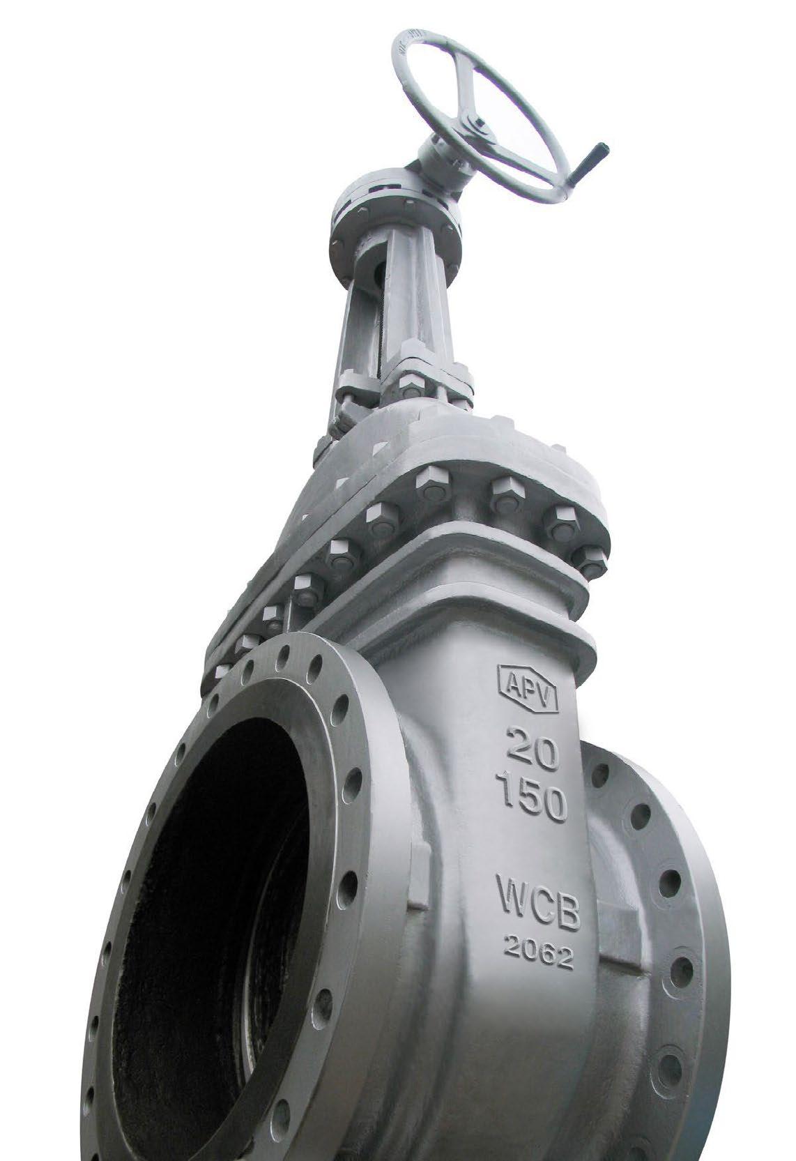
VALVE IDENTIFICATION
Each APV valve is identified with a nameplate. Below is an example.
When performing any work, ordering spare parts, or requesting technical support, please refer to this tag. The serial number, the part number and numbers cast on the side of the valve body are keys to proper valve identification.
GLOBE VALVES OS & Y - API623/BS1873/B16.34 Australian Pipeline Valve - Installation, Operation and Maintenance Manual 6
SIZE DISC SEAT CLASS BODY DESIGN STEM GSKT PKG CWP@38º C ASME B16.34 50NB CF8M+ST#6 316+ST#6 300 WCB API600 316L SW316 GRPFE 30 BAR 200ºC MAX 1096287-2 G360 150AP34XUN-GBW-FE 6 3 4 5 2 11 12 13 8 9 10 1 7 ITEM DESCRIPTION 1 APV valve figure number which delineats the as-built valve type, body, trim, features, packing, NACE, etc. Refer Figure Number System Appendix C 2 Shell material (e.g. body, bonnet) 3 Closure member material 4 Seat material 5 Rated pressure class as per ASME B16.34. Section 2 6 Nominal pipe size 7 Serial/batch number & stock code 8 Packing material 9 Maximum CWP @ 38ºC 10 Maximum Temperature 11 Design Standard 12 Stem material 13 Bonnet gasket material
1.0 INSTALLATION
Piping should be properly aligned and supported to reduce mechanical loading on the end connections.
1.1 INSTALLATION POSITIONS
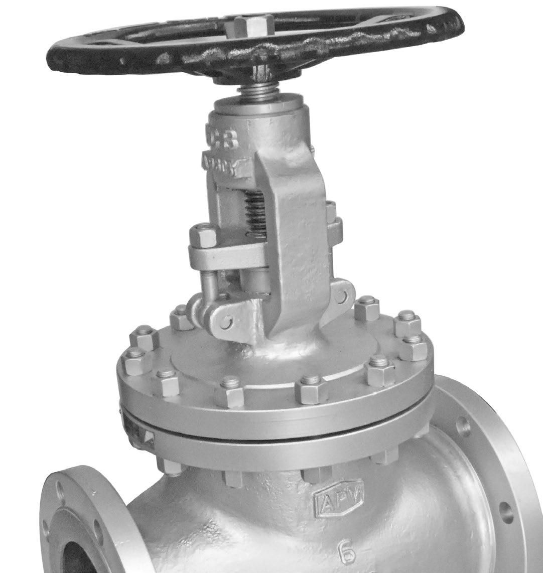
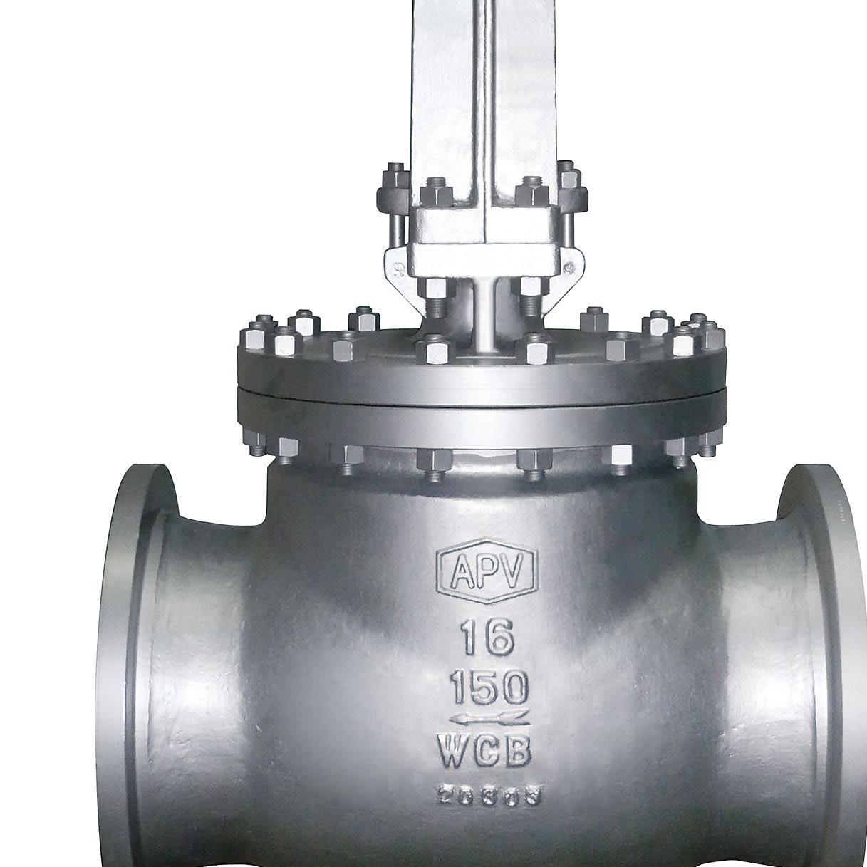
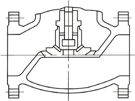
Globe valves are unidirectional and have the direction of flow indicated on the valve body. Globe valves should be installed with the stem in a vertical up position on horizontal lines with bonnet faced upward. Depending on size & class, globe valves with a fully guided disc and stem guide may also be installed at an angle between the vertical and horizontal axis which still allows for complete drainage (however, client must specify at time of order so the valve can be tested to ensure suitability). If installed with the stem below the horizontal axis, complete drainage is not possible and solids may accumulate in the valve bonnet, which will greatly affect the valve operation and service life.
Australian Pipeline Valve screw-down non-return globe valves are recommended for use in horizontal lines only. Right angle fully guided globe valves are recommended for vertical lines.
1.2 PREPARATION FOR INSTALLATION
• Install valves in full closed position to protect seat.
• Remove protective end caps or plugs and inspect valve ends for damage to threads, socket weld bores or flange faces.
• Thoroughly clean adjacent piping system to remove any foreign material that could cause damage to seating surfaces during valve operation.
• Verify that the space available for installation is adequate to allow the valve to be installed and to be operated.
Note
Ensure sufficient clearance for the stem in the full open position may cause the valve to be inoperable. Inadequate clearance for valve may add mechanical loading to the valve ends. Sufficient clearance should be allowed for threaded valves to be ‘swung’ during installation.
GLOBE VALVES OS & Y - API623/BS1873/B16.34 Australian Pipeline Valve - Installation, Operation and Maintenance Manual 7
FIGURE 1
1.3 END CONNECTIONS
1.3.1 Flanged Ends
Check to see that companion flanges are dimensionally compatible with the flanges on the valve body and make sure sealing surfaces are free of dirt.
Install the proper studs and nuts for the application and place the flange gasket between the flange facings.
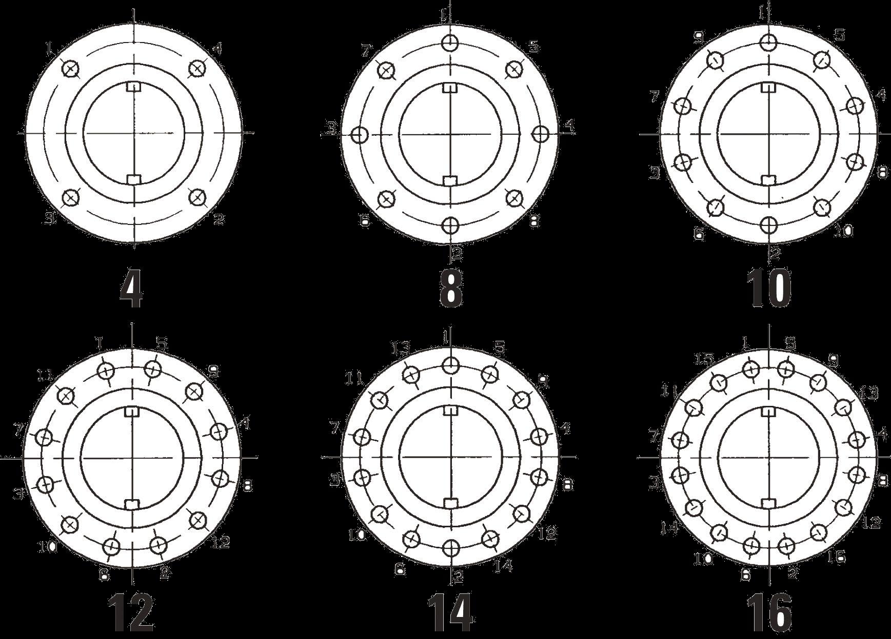
Stud nuts should be tightened in an opposing criss-cross pattern in equal increments to ensure even gasket compression. Refer Appendix A, Figure 11.
1.3.2 Buttweld Ends
Clean the weld ends as necessary and weld into the line using an approved weld procedure. Make sure the pipe and valve body material given on the nameplate or valve body is compatible with the welding procedure. (Refer our compatibility cross reference chart for equivalent pipe, valve & fitting grades).
1.3.3 Valve Installation by Welding
Leave valves assembled and in the lightly closed position during installation, welding and post-weld heat treatment. This will prevent the valve seat from floating or distorting during the process. After welding completion, open the valve and flush line to clean out any foreign matter.
A protective paint may have been applied to the weld ends on some valves, and it should be removed before welding, unless it is a deoxaluminate paint which acts as a welding flux and does not need to be removed.
Use the smallest electrodes and the minimum amperage possible consistent with approved welding procedures. This will help to minimise warpage in the seat areas. Tack weld should be ground out before completing the root pass in that area.
Valves of carbon steel should be allowed to cool slowly. The valve may be covered with a heatinsulating blanket to promote slow cooling and limit the heat-affected zone. Appropriate industry standards should be followed for all PWHT.
The responsibility for welding of the valves into piping systems is that of those performing the welding. Refer to ASME B31.1, B31.3 etc. Written welding procedures covering all attributes of the process and materials to be welded shall be in accordance with Section IX of the ASME Boiler and Pressure Vessel Code and any additional requirements from the applicable piping code including any possible necessary localized PWHT depending on material specifications.
GLOBE VALVES OS & Y - API623/BS1873/B16.34 Australian Pipeline Valve - Installation, Operation and Maintenance Manual 8
1.4 POST-INSTALLATION PROCEDURES
After installation, the line should be cleaned by flushing to remove any foreign material. When caustics are to be used to flush the line, additional flushing with clean water is required. The valve should be opened and closed after installation to ensure proper operating function.
With the line pressurised, check the valve end connections, body to bonnet/cover joints and stem packing area for leaks. The packing may have to be tightened to stop packing leakage.
2.0 OPERATION
Globe valves are ideal for on/off service especially for frequent operation due to the short travel between open and closed. The globe design is heavy duty but the flow passage translates to flow resistance.
Globe valves should not be used continuously to openings less than 20% or else venturi effect will damage seat and disc. Never attempt throttling under 20% of travel stem. Any throttling will reduce the life of the seat and disc. Closer throttling, can result in higher pressure drops which may cause excessive velocities or cavitation and could cause vibration or high noise levels resulting in damage to the valve or adjacent components/structure.
Globe valves are multi-turn valves with a rotating stem and rising hand wheel (unless a guide bar/stem guide is fitted, then they are non rotating rising stem (see Figure 3). Standard plug disc globe valves can be used for some minor very short term flow regulation. Alternate disc types are available (see Figures 2 & 6). Where a guided disc is specified and a torque arm (guide bar) is fitted, globe valves will have a longer life when used for minor throttling applications but should still be used under 20% open.
All globe valves close rotating the hand wheel clockwise and open by rotating counter-clockwise.
Globe valves should not be left in the fully back seated position under normal operating conditions. The packing may dry out under these conditions and leak as the valve is closed.
A cool valve may leak through the gland when opened to hot fluid. Wait before tightening the packing as the problem may go away.
GLOBE VALVES OS & Y - API623/BS1873/B16.34 Australian Pipeline Valve - Installation, Operation and Maintenance Manual 9
2.1 COMMON DISC STYLES
Optional Torque Arm
Used in larger sizes and higher pressures the torque arm prevents stem movement which reduces wear on packing rings and enables better sealing as well as reducing torque. Non rotating stem, non rising handwheel, only the stem nut rotates. The arm also provides visual stem position indication and can be interfaced with position switches. Optional live loaded packing system is shown. Provides improved valve life for throttling applications.
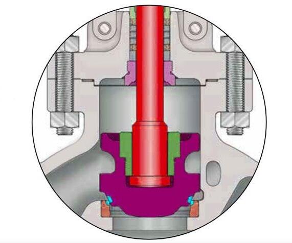
Optional Body Guided Disc
Body guided disc style eliminates side thrust and provides longer disc, seat and body life as well as ensuring positve shut-off and low closing torque. Provides improved valve life for throttling applications.
2.2 APPLICATIONS OF DIFFERENT DISC TYPES
Disc Functionality
The chart shows the stem opening related to the quantity of flow provided. It also indicates the grade of control over the fluid between the different type of discs.
Globe valves can be supplied with various types of disc depending on the application. Each style provides various levels of control. The correct selection of disc and material of construction and hard facing, will minimise wear caused by cavitation in more severe applications.
GLOBE VALVES OS & Y - API623/BS1873/B16.34 Australian Pipeline Valve - Installation, Operation and Maintenance Manual 10
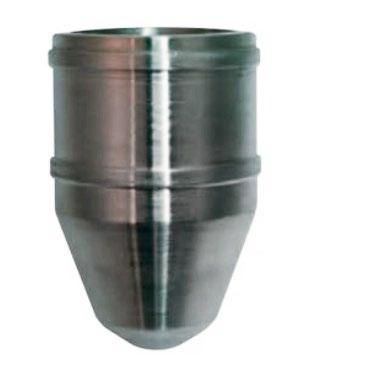
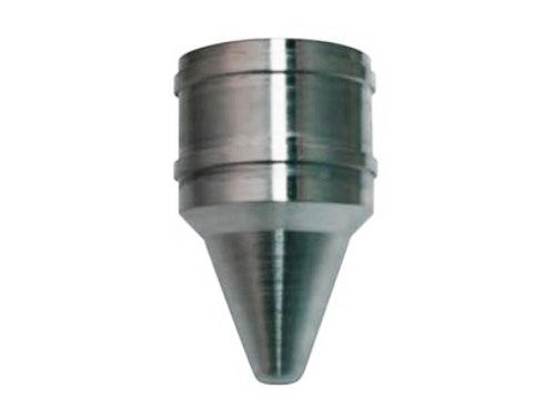
FIGURE 2 Plug Disc Ball Disc Body Guided Disc Parabolic Disc Equilibrated Disc Pin Guided Disc Vee Point Disc (Needle)
3
FIGURE
FIGURE 4 FIGURE 5 100% 75% 50% 25% 0 25% 50% 75% 100% % Flow % Stem Opening PLUG BALL PARABOLIC NEEDLE
It is similar to the ball type disc, but its parabolic design provides a higher flow regulation, having a better behavior against wear.
With the needle disc design the flow rate is better controlled than other disc designs and a fine regulation is achieved.
Lower half of the disc has a ball shape, permitting flow passage and flow stop, having the possibility to control partially the flow mainly in low pressure service.
The disc has a flat finished bottom, being the most common standard globe disc type, as well as simple and economical. Designed to permit flow passage or flow stop without a high degree of regulation. In larger sizes and higher pressures a guided disc and a stem guide is required for throttling applications. It is primarily used for positive shut off service and is also used to control flow. Whilst it has a taper, it is also available in superior longer and more tapered design variants depending on size, class and valve style.
Using a standard plug disc for flow control should be done with a high degree of caution - refer to API RP 615 section 5:3 and USA Process Industries Practices PCECV001.
Never use globe valves to throttle at under 20% of stem travel. Over 60% of stem travel may also significantly reduce valve life unless disc is body guided and a stem guide is fitted.
These valves are designed to operate within the pressure and temperature limits of ASME B16.34. Do not exceed these limits.
GLOBE VALVES OS & Y - API623/BS1873/B16.34 Australian Pipeline Valve - Installation, Operation and Maintenance Manual 11 FIGURE 6
TYPE DISC NEEDLE TYPE DISC BALL TYPE DISC PLUG TYPE DISC
PARABOLIC
3.0 MAINTENANCE
Proper safety equipment and apparel should be worn when preparing to service a valve. Observe the following general warnings:
• A valve is a pressurised mechanism containing energised fluids under pressure and consequently should be handled with appropriate care.
• Valve surface temperature may be dangerously too hot or too cold for skin contact.
• Upon disassembly, attention should be paid to the possibility of releasing dangerous and or ignitable accumulated fluids.
• Ensure adequate ventilation is available for service.
Tools Required: - aside from standard wrenches (for bonnet cap screws and packing gland nuts) the only tool needed for minor Australian Pipeline Valve valve maintenance is a packing hook.
3.1 GLAND PACKING REPLACEMENT
Special care is to be placed in the tightening of the gland nuts during installation, in order to get the proper packing adjustment and functionality.
The packing gland should be checked periodically in service and tightened as necessary to stop leakage around the stem. Tighten in a manner to develop uniform loading on the gland. Tighten only enough to stop the leak.
Over tightening will cause the packing to fail prematurely as well as increasing the force required to operate the valve.
If the leak cannot be stopped by tightening the gland nuts, it is necessary to add additional packing rings or completely repack the valve. Adding additional packing rings may damage the stem sealing system
GLOBE VALVES OS & Y - API623/BS1873/B16.34 Australian Pipeline Valve - Installation, Operation and Maintenance Manual 12
FIGURE 7
RIGHT
WRONG
over a longer term. While most Australian Pipeline Valve globe valves are equipped with a back seat feature, it is NOT ALLOWED TO REPACK THEM UNDER PRESSURE. For low emission service, proprietary genuine APV custom die formed fugitive emission packing must be used.
Note, PTFE packing has superior sealing properties compared to graphite, but is not firesafe.
When placing a new valve into service, Australian Pipeline Valve recommends a preliminary packing adjustment to verify proper packing load. Additionally, it is recommended that a Baseline Leakage Test be performed following installation, but prior to start-up.
During the packing life cycle, normal and routine maintenance of the packing arrangement must be administered. Normal cycle life will typically require 5 to 8 packing gland nut adjustments. Torque values vary depending upon valve size. Refer to the Packing Bolt Torque chart for the recommended torque values. Tighten the gland packing nuts clockwise. Do not over tighten or the valve will become too tight to turn (see 5.2.1.)
For normal operation in the open position, the stem should be backed off so that the backseat is not in contact. This permits the stem packing to assume it’s intended sealing function and not conceal unsatisfactory stem packing. In the event of stem packing leakage, the back seat can be used to stop stem leakage until circumstances permit a system shutdown and time for packing replacement. Stem packing replacement with the valve under pressure and back seated represents a hazard and should not be undertaken. The hazard is magnified as fluid pressure or temperature increases or when the fluid is toxic.
Under no circumstances should the back seat be used to allow gland packing replacement or repair while the valve and system are pressurised.
One of the most common misunderstandings is to believe that is the Globe valve is back seated (fully open position - and backseat sealing made), this will help to prevent wear of the packing rings. Unfortunately using the back seat in this way over a longer period of time, could result in some serious issues:
a) Since the body, bonnet, stem and disc heat up and expand at different rates, experience shows that valve can get jammed/blocked in back-seated position.
b) The gland packing will dry out faster since it’s not exposed to the product, and could immediately blow upon closing of the valve.
To avoid this, once the valve is brought into fully open position (back seated), turn the handwheel back on full turn.
Prior to replacing the packing rings, remove all pressure from the valve.
WARNING: If the backseat faces have been damaged by foreign material the backseat may leak into the packing chamber.
Australian Pipeline Valve PTFE
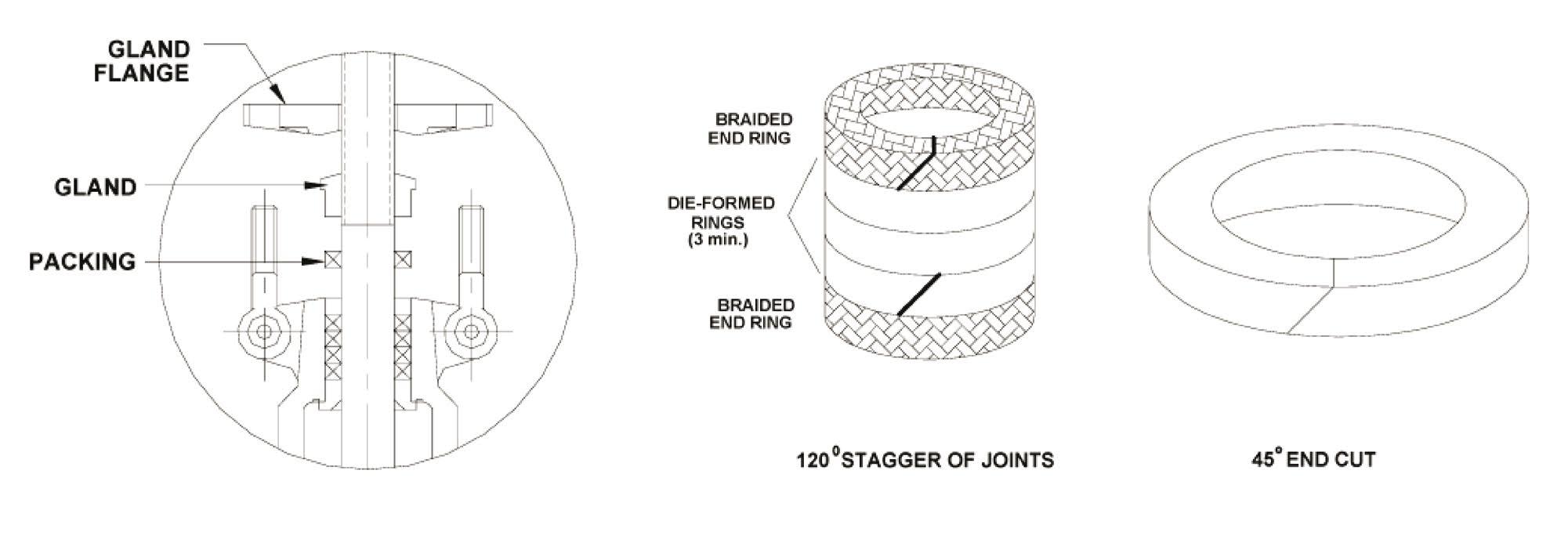
sets are usually die formed/moulded and have no end cut. As a result, these rings cannot be replaced without removing the valve bonnet. If the valve is to be repacked without removing the bonnet, care must be taken when removing the original packing not to scratch the valve stem sealing surface.
GLOBE VALVES OS & Y - API623/BS1873/B16.34 Australian Pipeline Valve - Installation, Operation and Maintenance Manual 13
and graphite packing
A compatible ribbon packing system or equivalent braided packing stock should be used but the emissions will be higher. Also, torque may increase. A stuffing box corrosion inhibitor is recommended. The joints in the packing rings should be diagonally cut. When installing the rings, care should be taken to stagger the ring joints. Where it is necessary to repack the valve in-line, ensure the line pressure is totally isolated prior to attempting to repack valve in-line. Wear anti-splash eye protection goggles.
Especially in the case of dangerous, hazardous, volatile, caustic or flammable liquids or gases, do not ever attempt to repack the valve in-line even if pressure has been isolated.
Other specialty packing such as V-ring Teflon will require that the valve be disassembled if repacking is required.
3.2 REPAIRS
Due to the relatively low replacement cost of small diameter standard carbon steel valves under 100NB (4”), it is usually less expensive to replace the complete valve than to have maintenance personnel effect repairs. Generally, the only justifiable repairs are replacement of packing and gaskets as previously described. However, see Sections 4.0 and 5.0 for further maintenance.
Always replace the bonnet gasket whenever a valve is disassembled. ‘Pressure seal’ style bonnet valves require a proprietary (usually soft metal) gasket. After removing valve from line, use adequate force to remove bonnet. Gasket seating surfaces should be scraped clean (avoid radical marks). Bonnet bolts should be tightened in a diagonal pattern at several different increasing torque settings until the final recommended torque value is attained. Refer to Tables A & B in Appendix A, including Figure 11.
Other specialty packing such as V-ring Teflon will require that the valve be disassembled if repacking is required.
Note
During maintenance or servicing of the valve, all replacement parts must be the same as the original specification (parts dimensions and materials). End user may also purchase the spare parts such as packing, gaskets, bolt/nuts, etc. when ordering the valve. With the new packing, gasket or bolt/nuts installed, the valve must be applicable pressure testing prior to installation and service.
GLOBE VALVES OS & Y - API623/BS1873/B16.34 Australian Pipeline Valve - Installation, Operation and Maintenance Manual 14
4.0 MAINTENANCE
PROCEDURES
4.1 PREVENTATIVE MAINTENANCE AND PERIODIC INSPECTIONS
APV recommends that periodic inspections be carried out on all valves. The frequency of these inspections depends on the severity of the service and the frequency of the valve operation. As a minimum, all valves should be inspected quarterly to ensure proper operation and discourage the damage compounding effects of leakage. The following list details the specific valve types and areas requiring inspection and maintenance.
Items to Inspect Stop Check Globe
Check all lubrication points
Check body/bonnet join for leaks
Check for packing leaks
Check stem threads for wear
Ensure stem and seal areas are free from debris
If conditions permit, operate valve
Inspect all external connections
Inspect condition of actuator and/or gear operators (if applicable)
Inspect valve for obvious damage
Do not remove or loosen the packing gland or bonnet bolts while the valve is pressurised.
1. The valve stem packing should be inspected monthly. If the stem packing shows signs of leakage, simply tighten the adjusting nuts to compress the packing. Do not over tighten the adjusting nuts as this will make operation of the valve more difficult. If, after tightening the adjustments nuts to their fullest extent, the leakage does not stop, it is then necessary to replace the stem packing. It is not recommended that additional packing rings be added to the stuffing box as this may cause damage to the stem sealing system. For packing replacement see Section 5.2.
2. Regular maintenance of the valve is required to assure smooth operation. Stem threads should be inspected and lubricated frequently to ensure ease of operation. APV valves are supplied with the stem threads engaging the yoke nut pre-greased. These components should be kept constantly lubricated by applying the grease directly on the stem when the valve is in the open position or through the grease injector in the yoke nut when provided. Lubrication/greasing of the stem should be conducted every six months or more often as needed, based on the environment the valve is installed. Inspection should confirm that the valve is sealing properly. Stem packing should be inspected at least
GLOBE VALVES OS & Y - API623/BS1873/B16.34 Australian Pipeline Valve - Installation, Operation and Maintenance Manual 15
every six months to ensure zero leakage from the packing chamber. For water & oil service, regular maintenance should be scheduled every 3 months. For gas and more corrosive mediums, inspection and maintenance should be completed once a month.
3. Bonnet bolt tension should be checked periodically when valves are used in high temperature applications where creep may occur. Refer Appendix A, Tables A & B and Figure 11 for torque figures and tightening sequence. Although leaks through bonnet ring or spiral gaskets are rare, erosion or corrosion could cause bonnet seal to fail. In these cases, a new gasket is required. Refer Section 5.3 for replacing bonnet gasket.
4. With problematic service applications it is recommended that the valve be periodically at least partially stroked to ensure valve functions and to ensure there is no product deposits entering into seat or stem area which may render operating more difficult. Duration depends on service, criticality, etc. However, it also must be factored in that if there are impurities or particulates in the line, likely to be built up in the seat area, each operation could reduce seat life proportionately.
5.0 EXTRAORDINARY MAINTENANCE
5.1 STEM
If the stem locks or “freezes”, causes can generally be attributed to dry worn packing or a dry yoke nut. In either of these cases, the following service is required:
a) Unscrew gland nuts, remove the gland flange and bushing to expose stem packing and lantern ring/ packing spacer (where applicable). Replace stem packing if it is damaged. If the lantern ring is seized, completely disassemble the stem and replace the lantern ring (where one is fitted). Smaller sizes and larger sizes with fugitive emission packing sets do not require spacers/lantern rings as standard.
b) Check lubrication of yoke nut. If it is dry, remove the yoke nut but determine if there is evidence of seizure marks. If so replace it with a new yoke nut.
5.2 GLAND DISASSEMBLY & REPLACEMENT OF STEM PACKING
In those cases where the valve cannot be removed from the piping system, it is important that prior to servicing, the valve be opened to its fullest extent and purged of any pressure/fluid (protective safety goggles should be worn). Partially unscrew nuts to reduce the compression load on the stuffing box. Next, if so required, remove the plug to check that there is no leakage. Remove the stem packing.
5.2.1 Stem Packing Replacement
First remove the valve from the line. To prevent injury ensure that all fluid and pressure is removed from the valve both upstream and downstream before removal and disassembly. When removing drain or stem plugs, wear protective eye masks to avoid injury.
GLOBE VALVES OS & Y - API623/BS1873/B16.34 Australian Pipeline Valve - Installation, Operation and Maintenance Manual 16
1. Check tightness of valve operation to serve as reference when re-tightening. Remove gland nuts and the hook. Lift the gland up the stem clear away from the packing chamber.
2. Remove the defective packing rings with a sharp tool or packing hook. Do not scratch or score the machined surfaces of the stem or packing chamber.
3. Examine the machined surfaces of the stem and packing chamber. Remove any scratches, scoring or burrs with an emery cloth or by hand filing. Clean the stem with a solvent soaked rag. Scratches to the stem and the packing chamber no deeper than 0.25mm (0.010”) can be removed by polishing the surface with a buffing wheel. The surface finish of the packing chamber should be Ra 3.2µm and the stem should be Ra 0.5 ~ 0.8µm.
4. Count original number of rings and measure x-section thickness. If original packing cannot be counted or measured, follow the steps below:
a) Measure the stem diameter (OD), stuffing box diameter (ID) and stuffing box depth (d)
b) Packing x-section (R)=(ID - OD)/2
c) # rings = (1.25 x d)/R
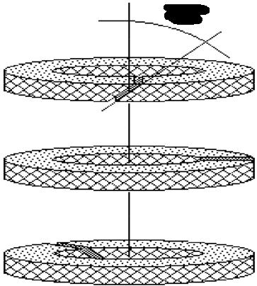
5. Install new packing. Use a genuine APV low emission, low friction packing set. If using standard coils of packing material: cut each ring at a 45 degree angle and stagger the joints at 120 degrees, every fourth joint will be in the same position as the first. Install rings individually using a split ring spacer, compressing each ring by hand tightening + 1/4 turns on each packing gland nut.
6. When packing chamber becomes filled with packing, reassemble gland and gland flange. Alternate tightening packing gland flange nuts 1/4 turn at a time until eyebolts begin to get tight. (If gland travels more than the height of one packing ring into the packing chamber, insert one more ring and repeat step 6. until chamber is filled.)
7. Compare valve operation to original tightness. If valve operation is considerably tighter than original operating tightness, back off 1/4 turn on each gland nut & recheck tightness. Where proprietary packing sets are used such as (example only) APV-Enviroseal M600, Garlock EVSP 9000, Burgmann 6070 or Chesterton 1622 please consult packing manufacturer’s torques. The serialised as-built drawing will indicate the packing used, please refer to APV. Various packing types, materials, proprietary combinations and styles with and without spacers/lantern rings, etc, and torque limitations of some bolting materials, bonnet design variations, stuffing box and stem smoothness, means it is not possible to safely publish recommended torques for packing. In addition, higher pressure ratings will require higher torques especially if media types are hazardous or more leak searching prone such as gas.
8. Several hours after a repacked valve has been returned to service, inspect the packing area to ensure full compression, tight bolting and no leakage. Should leakage occur, tighten gland nuts at 1/4 turn increments until leakage stops.
We recommend using graphite packing with inbuilt lubrication such as APVEnviroseal M600 fugitive emission packing as adding grease to the bore can attract particles that damage the packing and the grease could cause product contamination. For an assured seal the only solution is to machine the stem and stuffing box smoothness as shown in figure 8.
GLOBE VALVES OS & Y - API623/BS1873/B16.34 Australian Pipeline Valve - Installation, Operation and Maintenance Manual 17
Note
Stuffing Box* Stem Packing*
* Example only, refer to as-built drawing. Genuine APV die formed/moulded packing sets are recommended for fugitive emission service. Combination set shown is example only, refer to as-built drawing. Note
The stem packing style will vary according to valve size, type and class as well as the stem packing material specified. Examples include combination sets, wire reinforced braided packing, PTFE Chevron moulded sets, live loaded sets.
5.3 BONNET DISASSEMBLY & STEM REPLACEMENT
Before disassembly:
1. Check that the line is in a complete shut down phase then remove the valve from the line.
2. Pre-order all necessary spare gland packings and jointing gaskets.
3. Open the valve slightly by turning the handwheel anti-clockwise and loosen the gland.
4. Put identification marking on valve body, bonnet, disc, yoke and actuator. This helps to avoid mismatching of parts at the time of re-assembly.
5. If the bolts and nuts are too tight, apply deep penetrating oil then unscrew.
Refer Section 5.3.1 and 5.3.2 below for removing the bonnet.
To replace the stem when the valve is completely disassembled for general maintenance follow this procedure:
• Open valve half way then remove bonnet bolts and nuts.
• With the bonnet removed, unscrew the gland bolts the lift up gland flange exposing the stem packing.
• Remove hand wheel then turn stem to release it from the yoke nut and remove from stuffing box.
• Check condition of back seat bushing for seizure marks. If apparent, order replacement parts.
• If required, turn the bonnet upside down and remove lantern ring.
• If so equipped, remove stem packing below the lantern ring.
GLOBE VALVES OS & Y - API623/BS1873/B16.34 Australian Pipeline Valve - Installation, Operation and Maintenance Manual 18 BRAIDED END RING DIE-FORMED RINGS BRAIDED END RING 45º 120° STAGGER OF JOINTS* 45° END CUT*
Always be sure that the valve is de-pressurised and isolated prior to performing any maintenance work. Do not attempt to repair valve in-line if volatile, dangerous, hazardous or flammable service.
5.3.1 Bolted Bonnet Removal & Gasket Replacement
Always replace the bonnet gasket whenever a valve is disassembled. Gasket sealing surface should be scraped clean (avoid radial marks).
1. Disassemble all cover bolts and nuts.
2. Lift up the bonnet using lifting lugs where provided, evenly break the bonnet seal with a lever if required before lifting the bonnet off (where required with a sling and mechanical lifting device).
3. Turn the handwheel clockwise to remove the stem assembly, carefully holding the stem; If necessary, remove the spot weld between the disc and disc nut, and then remove the disc from the stem.
4. Remove the packing flange and packing gland, use a packing hood or similar tool to remove the packing from the packing bore, take care that you do not damage the packing bore sealing surface finish.
5. Remove the bonnet gasket from the body. When removing the handwheel: if necessary, remove any spot welding first, then remove hand wheel, gland, and bearing and stem nut in sequence.
6. For valves fitted with an actuator or gear operator: follow the order in removing the top flange bolts, nuts, packing gland bolts, nuts, spring, disc. Remove the gear box or actuator from the top, and carefully observe the outside configuration of the gear box of the actuator.
7. If necessary, loosen the yoke/bonnet bolt/nut, separate the yoke and the bonnet (some valve configurations, yoke and bonnet is one part).
8. Unless it has been damaged, we do not recommend removal of the back seat.
9. Clean gasket surface areas, replace gasket and refit bonnet as detailed below.
5.3.2 Pressure Seal Bonnet Removal & Gasket Replacement
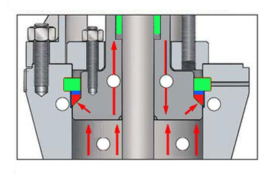
In 900 to 2500 class a ‘pressure seal’ bonnet may be specified. The bonnet bolts effect a seal on the pressure seal joint which forces the bonnet onto the pressure seal gasket which in turn is forced up hard against the outer body, refer example Figure 9 below. The higher the line pressure, the higher the sealing force against the gasket, further tightening the seal. The thrust rings are embedded in the body. Live loading bonnet bolt washers are available which can be tightened to ensure a constant force is applied to the bonnet gasket.
GLOBE VALVES OS & Y - API623/BS1873/B16.34 Australian Pipeline Valve - Installation, Operation and Maintenance Manual 19
Note Welded bonnet valves
can be replaced but otherwise are not repairable.
The procedure to remove a pressure seal bonnet is as follows.
1. After disassembling the gland (refer Section 5.2) remove the bonnet bolts (or threaded breech-lock bonnet).
2. Insert a knock-out pin (where applicable) into the drilled hole so the segmented thrust ring can be driven out from the retaining groove.
3. The optional S/S protective ring and the gasket can then be removed.
4. Clean the gasket area and always fit a new gasket before reassembly. FIGURE
Note, the above drawing is indicative only and the design varies according to size/class. There are different designs of pressure bonnet: - locknut type (breech lock), bonnet take-up type (bolted yoke arm) and the bolted style shown in Figure 9 hence, refer to APV as-built drawing.
Only an experienced APV approved valve repair professional should attempt disassembly of pressure seal bonnet valves.
5.4 VALVE REASSEMBLY
The procedure to reassemble the valve is as follows:
Re-insert the stem through the stuffing box taking special care to reassemble parts in sequence. If so equipped, avoid allowing the lantern ring to slide into the stuffing box. If the valve is equipped with a lantern ring, first insert packing rings into the stuffing box followed by a lantern ring (where applicable). Next, insert the remaining packing rings into the stuffing box and compress using the gland and flange. Then, reassemble nuts and tighten.
GLOBE VALVES OS & Y - API623/BS1873/B16.34 Australian Pipeline Valve - Installation, Operation and Maintenance Manual 20
1 4 2 3 4 3
9 Bonnet Spacer Ring Yoke Bolts Top works yoke Bonnet Bolts Stem Packing Thrust Ring Bridgeman pressure activated gasket Body
Hole to remove bonnet gasket
Optional S/S protective ring
3 2 1 4
Bonnet can move up or down as pressure increases and decreases Line pressure Line pressure further tightens Bridgeman gasket seal
Note, the stem must slide freely through the stuffing box without applying excessive force, finally, install the bonnet gasket making sure it is not damaged. The gasket should be replaced if there is any question as to its performance (Refer Sections 5.3.1 & 5.3.2).
Raise the bonnet, making sure the stem is in the half open position, then connect disc to stem. Lower bonnet on to the valve body making sure that the disc fits exactly into body guides and the bonnet is properly seated. Align holes and tighten bonnet nuts taking care that excessive forced is not used to avoid damaging the gasket. Hydrostatically test the valve to ensure that there is no leakage.
5.5 DISASSEMBLY OF YOKE NUT
When necessary use the following procedure for disassembling and replacing yoke nut:
a) Direct hand operated valves (hand wheel)
• Remove set screw;
• Unscrew hand wheel nut;
• Remove hand wheel;
• Unscrew yoke nut retaining nut, removing spot welds if necessary.
Reverse the procedure for reassembly
b) Bevel gear operated valves
• To remove the bevel gear from the valve, unscrew nuts and turn the hand wheel in the open direction indicated by the arrow until the drive nuts are disengaged from the stem.
• To check the condition of the drive nut or bearing, unscrew the retainer ring and remove drive nut and bearing. If damaged, a new drive nut or bearing is necessary.
5.6 DISC AND SEAT REPAIR
An indication of valve leakage is a pressure loss in the high pressure line side after a valve has been properly closed. In the case of hot water or steam lines, note whether the downstream pipe remains hot beyond the usual length of time. This type of leak may be the result of a distorted seat caused by improper welding of the valve into the pipeline or seating damage caused by foreign particle matter or by stress relieving temperatures that may have been used during installation.
Leaks can also develop from failure to close the valve tightly, resulting in high-velocity flow through a small opening. Trim materials such as CR13 (410) and especially Stellite are corrosion and erosionresistant, but grooves, pit marks or other surface irregularities may still form on the mating surfaces. Valves which leak should be repaired as quickly as possible to prevent greater damage caused by high velocity. Leakage through seats and disc cannot be verified when valve is in service. However, when leaks are identified, immediate action is necessary. Any delay can permanently damage the seat or disc seal surfaces.
To repair or replace disc or seats, the valve must be removed from the line (refer Section 5.2) then use the following procedure:
GLOBE VALVES OS & Y - API623/BS1873/B16.34 Australian Pipeline Valve - Installation, Operation and Maintenance Manual 21
• Make sure that the valve is not under pressure before unscrewing bonnet nuts.
• Remove bonnet, being careful not to damage the gasket.
• Remove bonnet when disc is in half open position.
• Lift up bonnet until disc is disconnected from guides.
If seat surfaces show signs of seizing, pitting, grooves or other defects not deeper that 1.0mm (1/16”) it is possible to repair seating surfaces to its original condition by relapping the surface with line grain abrasive paste, creating a perfect tightness once again.
Defects having a depth exceeding .8mm (1/32”) cannot be repaired by lapping, in this case, parts must be replaced, or re-metallised or reground by an approved APV approved professional valve reconditioning service centre. Refer 5.7 below.
It is recommended that the face of the disc be blued to check for contact of seating surface after final lapping. For re-assembly of valves use the procedure outlined under paragraph 5.4.
5.7 DISC & SEAT RELAPPING/MACHINING
If there are indentations or pitting marks no deeper than 0.12mm (0.005”), a cast iron lapping disc with the proper seat angle must be used with a suitable lapping compound to roughen the surface first with the use of a new or refurbished original disc, use a fine lapping compound to final lap the disc and seat together.
Note, For body seat damage exceeding 0.12mm (0.005”) up to a maximum (for valve a seat angle of 30°), .8mm (1/32”) can be removed by grinding with the automatic grinding machines or a lathe by an APV approved valve repairer. For major seat damage use 60 – 80 grit, diamond or micron Alumina stick on abrasive discs, and finish with fine grit 180 and up. For minor imperfections use medium coarse 120 grit stick on abrasive discs and finish with fine grit, 180 and up.
6.0 REASSEMBLY
1. Re-assemble in reverse order of disassembly.
2. Bonnet bolts should be tightened in a diagonal pattern at several different increasing torque settings in accordance with the recommended torque value (see Tables B and C in Appendix A, and Figure 12).
3. Apply a thin layer of light oil on the sealing surface to avoid any scratches that may occur during the assembly process.
4. When re-assembling the valve, ensure that all orientation marks stamped or marked on the valve body, bonnet and other components are installed in the same orientation within the valve body and bonnet. Inspect and ensure that all components are thoroughly clean before installing into the valve body or bonnet. All rust and dirt should be removed with a wire brush or emery cloth. Oil solids and grease adhered to the valve stem and yoke should be removed with approved solvents. All threaded components should be well lubricated, paying special attention to the valve stem and yoke nut threads.
APV recommended lubricants are referenced in Section 4.1
GLOBE VALVES OS & Y - API623/BS1873/B16.34 Australian Pipeline Valve - Installation, Operation and Maintenance Manual 22
5. Install the stem to the bonnet, install the disc to the stem T-Head, install the disc nut into the disc (spot welding), then install the bonnet assembly into the body.
6. Install new bonnet gasket, stem packing, and then packing gland and gland flange.
Note: For packing installation see Section 5.2
7. Ensure that all studs and nuts are clean and free of rust, corrosion, burrs and previous lubricants. APV recommends installing new bolting when assembling body and bonnet connections. APV recommends coating the stud threads and surface under the nut with molybdenum disulfide. All tightening of the bolting should be by hand; followed by the appropriate tightening sequences and torque charts outlined in Appendix A. It is important to follow proper torque procedures. Each bolt should be torqued in steps of approximately 20% of final torque. Recheck all bolting once completed.
8. Over torque can cause deformation of the body/bonnet flange causing leakage. Failure to properly follow the tightening sequence will result in the gasket not being compressed evenly, resulting in gasket leakage.
9. To assure the valve is sealing properly, perform the required pressure testing per API 598 Standard.
Never use impact device to tighten the bolting on the body/bonnet connections. Use suitable designed mechanical devices such as hand torque wrenches for tightening and refer to Appendix A. Torque wrenches and standard wrenches may be used in combination when performing tightening sequences.
GLOBE VALVES OS & Y - API623/BS1873/B16.34 Australian Pipeline Valve - Installation, Operation and Maintenance Manual 23
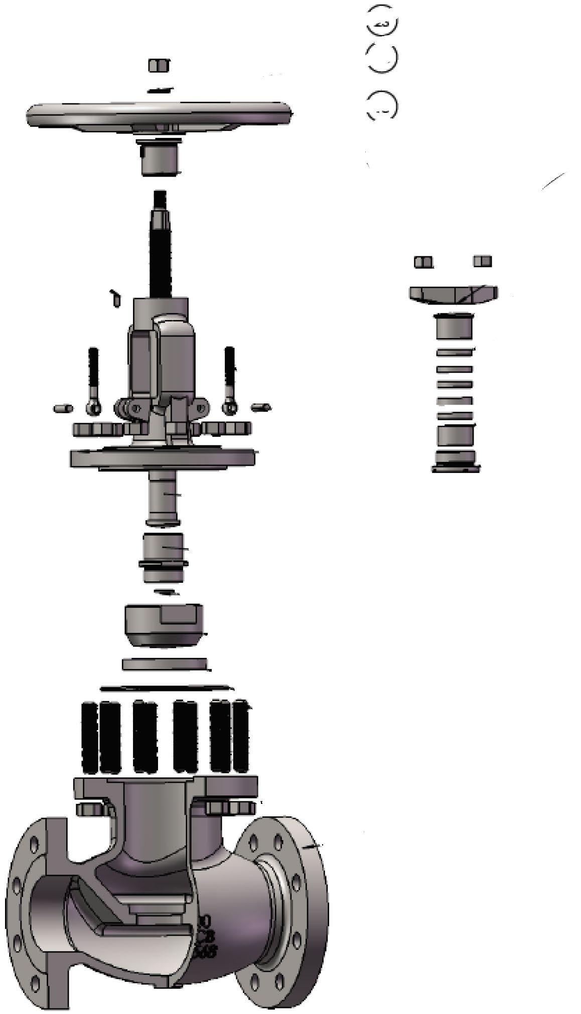
Typical Bolted Bonnet Globe Valve Exploded View
FIGURE 10
Lock Washer
O-Ring
Grease Nipple
Screw
Support Plate
Guide Plate
Stud & Nut (Body & Bonnet)
Packing Set
Spacer
Bonnet Bush
Disc Nut
Disc Washer
Hand Wheel Nut
Hand Wheel
Retainer Nut
Yoke Sleeve
Thrust Bearing
Gland Nut
Gland Flange
Gland Eyebolt
Collar Pin
Circlip/Pin
Bonnet
Stem
Disc Gasket
Body
Rising Stem - Non Rotating Style c/w stem guide plate (Refer Appendix B for example of conventional rotating stem rising hand wheel style) Example only, refer to as built drawing as there are numerous designs for different sizes, classes, bonnet types and design standards.
GLOBE VALVES OS & Y - API623/BS1873/B16.34 Australian Pipeline Valve - Installation, Operation and Maintenance Manual 24
APPENDIX A
INDICATIVE BONNET BOLTING (BOLTED BONNET) TORQUE NM (IMPERIAL)
Note:
(1) Torque tolerance ±10%.
(2) For temperatures above 750°F (400°C) use 75% of the torque values. In high temperature services, there is a possibility of creep in the bonnet studs. Regular checking of the bonnet - studs for tightness, would help prevent leakage through the bonnet gasket.
(3) Above torque values are with the bolts lubricated.
(4) Values above are based on 206.85 Mpa/ 30,000 psi bolting stress and lubricated with heavy graphite and oil mixture or a copper based anti-seize grease.
(5) Do not exceed by more than 25% of values stated when emergency torquing is required.
(6) All bolts shall be torqued in the pattern as shown in Figure 5 on page 26 to ensure uniform gasket loading.
(7) Optimum torque can vary depending on type of body gasket but do not increase torque more than 10% above those shown.
(8) Consult us for other bolt material.
(9) Most B8M and B8 bolts are class 1 so do not assume class 2 unless you are sure. Refer to certificates or as-built drawing.
Bolt tensions shown must be decreased by 25% when other or no lubrication used. Non lubricated bolts can have an efficiency of less than 50% the torque of values stated. Indicative torques are shown only, different body gasket systems, different sizes & classes, etc., will have different torque requirements. Furthermore, other stud grades can have much lower torques depending if class 1 or class 2 and or above variables.
GLOBE VALVES OS & Y - API623/BS1873/B16.34 Australian Pipeline Valve - Installation, Operation and Maintenance Manual 25
TABLE A STUD SIZE inch-TPI Bolting Material B7/B7M/B16/L7/L7M/L43/660 Cl.A/ UNS N07718/UNS 09925 B8 Cl.2/B8C Cl.2/B8M Cl.2/ B8T Cl.2/XM-19 UNS N06625 Gr 1 1/4-20 UNC 7 7 5 5/16-18 UNC 15 15 10 3/8-16 UNC 25 25 15 7/16-14 UNC 40 40 25 1/2-13 UNC 60 60 40 9/16-12 UNC 90 90 60 5/8-11 UNC 120 120 80 3/4-10 UNC 215 215 145 7/8-9 UNC 345 315 230 1-8 UNC 520 475 345 1.1/8-8 UN 725 625 510 1.1/4-8 UN 1000 880 715 1.3/8-8 UN 1460 975 975 1.1/2-8 UN 1925 1285 1285 1.5/8-8 UN 2480 1655 1655 1.3/4-8 UN 3140 2090 2090
Note
APPENDIX A - CONT.
Note:
(1) Torque tolerance ±10%.
(2) For temperatures above 750°F (400°C) use 75% of the torque values. In high temperature services, there is a possibility of creep in the bonnet studs. Regular checking of the bonnet - studs for tightness, would help prevent leakage through the bonnet gasket.
(3) Above torque values are with the bolts lubricated.
(4) Values above are based on 206.85 Mpa/ 30,000 psi bolting stress and lubricated with heavy graphite and oil mixture or a copper based anti-seize grease.
(5) Do not exceed by more than 25% of values stated when emergency torquing is required.
(6) All bolts shall be torqued in the pattern as shown in Figure 5 on page 26 to ensure uniform gasket loading.
(7) Optimum torque can vary depending on type of body gasket but do not increase torque more than 10% above those shown.
(8) Consult us for other bolt material.
(9) Most B8M and B8 bolts are class 1 so do not assume class 2 unless you are sure. Refer to certificates or as-built drawing. Note
Bolt tensions shown must be decreased by 25% when other or no lubrication used. Non lubricated bolts can have an efficiency of less than 50% the torque of values stated. Indicative torques are shown only, different body gasket systems, different sizes & classes, etc., will have different torque requirements. Furthermore, other stud grades can have much lower torques depending if class 1 or class 2 and or above variables.
GLOBE VALVES OS & Y - API623/BS1873/B16.34 Australian Pipeline Valve - Installation, Operation and Maintenance Manual 26
INDICATIVE BONNET BOLTING (BOLTED BONNET) TORQUE NM
TABLE
STUD SIZE (mm) Bolting Material A193 B7 A193 B7M A193 B16 A193 B8(M) 1 A193 B8(C) 2 A193 B8M 2 A320 L7 A320 L7M M10 16 45 34 45 13 42 40 45 34 M12 18 77 59 77 22 74 70 77 59 M14 21 123 93 123 35 118 112 123 93 M16 24 191 145 191 54 182 173 191 145 M18 27 264 200 264 75 251 239 264 200 M20 30 373 283 373 106 283 283 373 283 M22 34 509 386 509 144 386 386 509 386 M24 36 644 489 644 183 489 489 644 489 M27 41 945 716 945 267 586 586 945 716 M30x3 46 1326 1006 1326 375 823 823 1326 1006 M33x3 50 1798 1364 1798 509 856 856 1798 1364 M36x3 55 2371 1799 2371 671 1128 1128 2371 1799 M39x3 60 3054 2316 3054 863 1453 1453 3054 2316 M42x3 65 3856 2926 3856 1091 3856 2926 M45x3 70 4788 3622 4788 1354 4788 3633 M48x3 75 5866 4446 5860 1657 5860 444 M52x3 80 7522 5706 7522 2127 7522 5706 M56x3 85 9471 7185 9471 2678 9471 7185 M60x3 90 11732 8900 11732 3318 11732 8900 M64x3 95 14325 10868 14325 4051 14325 10868 M68x3 100 15608 13106 15608 4885 15608 13106 M72x3 105 18616 15632 18616 5826 18616 156.32 M76x3 110 21988 18463 21988 6882 21988 18463
(METRIC)
A1
APPENDIX A - CONT.
For ‘pressure seal’ bonnet consult APV for torques (where bolting is applicable).
INDICATIVE WRENCH SIZE FOR BONNET BOLTING
TABLE B
3/8”
1/2”
9/16”
5/8”
3/4”
7/8”
1”
1-1/8”
1-1/4”
125mm (5”)
150mm (6”)
225mm (9”)
300mm (12”)
450mm (18”)
600mm (24”)
750mm (30”)
900mm (36”)
1050mm (42”)
When torque wrenches are not available or suitable, the use of standard wrenches and guidelines will apply to avoid over torque or damage to the valve.
Never use impact devices to tighten the bolting on the body/bonnet connections. Use suitable designed mechanical devices such as hand torque wrenches for tightening and refer to Table A, Appendix A. Torque wrenches and standard wrenches may be used in combination when performing tightening sequences.
GLOBE VALVES OS & Y - API623/BS1873/B16.34 Australian Pipeline Valve - Installation, Operation and Maintenance Manual 27
Note
Bolt size Length of wrench (inches)
APPENDIX A - CONT.
INDICATIVE GLAND BOLTS
Note:
(1) Torque tolerance ±10%.
(2) For temperatures above 750°F (400°C) use 75% of the torque values. In high temperature services, there is a possibility of creep in the bonnet studs. Regular checking of the bonnet - studs for tightness, would help prevent leakage through the bonnet gasket.
(3) Above torque values are with the bolts lubricated.
(4) Values above are based on 206.85 Mpa/ 30,000 psi bolting stress and lubricated with heavy graphite and oil mixture or a copper based anti-seize grease.
(5) Do not exceed by more than 25% of values stated when emergency torquing is required.
(6) All bolts shall be torqued in the pattern as shown in Figure 5 on page 26 to ensure uniform gasket loading.
(7) Optimum torque can vary depending on type of body gasket but do not increase torque more than 10% above those shown.
(8) Consult us for other bolt material.
(9) Most B8M and B8 bolts are class 1 so do not assume class 2 unless you are sure. Refer to certificates or as-built drawing.
Bolt tensions shown must be decreased by 25% when other or no lubrication used. Non lubricated bolts can have an efficiency of less than 50% the torque of values stated. Indicative torques are shown only, different body gasket systems, different sizes & classes, etc., will have different torque requirements. Furthermore, other stud grades can have much lower torques depending if class 1 or class 2 and or above variables.
GLOBE VALVES OS & Y - API623/BS1873/B16.34 Australian Pipeline Valve - Installation, Operation and Maintenance Manual 28
TABLE C STUD SIZE (mm) Bolting Material A193 B7 A193 B7M A193 B16 A193 B8(M) 1 A193 B8(C) 2 A193 B8M 2 A320 L7 A320 L7M M10 16 27 21 27 8 26 24 27 21 M12 18 47 36 47 14 45 42 47 36 M14 21 74 56 74 21 71 68 74 56 M16 24 115 87 115 33 110 104 115 87 M18 27 159 120 159 45 151 144 159 120 M20 30 224 170 224 64 170 170 224 170 M22 34 306 232 306 87 232 232 306 232 M24 36 378 294 387 110 294 294 387 294 M27 41 567 430 567 161 352 352 567 430 M30x3 46 796 604 796 225 494 494 796 604 M33x3 50 1079 819 1079 306 514 514 1079 819 M36x3 55 1423 1080 1423 403 677 677 1423 1080 M39x3 60 1833 1390 1833 518 872 872 1833 1390 M42x3 65 2314 1756 2314 655 2314 1756 M45x3 70 2873 2180 2873 813 2873 2180 M48x3 75 3516 2668 3516 995 3516 2668 M52x3 80 4514 3424 4514 1277 4514 3424 M56x3 85 5683 4311 5683 1607 5683 4311 M60x3 90 7040 5340 7040 1991 7040 5340 M64x3 95 8595 6521 8595 2431 8595 6521 M68x3 100 9365 7864 9365 2931 9365 7864 M72x3 105 11170 9380 11170 3496 11170 9380 M76x3 110 13193 11078 13193 4130 13193 11078
Note
APPENDIX A - CONT.
BOLT TIGHTENING SEQUENCE
GLOBE VALVES OS & Y - API623/BS1873/B16.34 Australian Pipeline Valve - Installation, Operation and Maintenance Manual 29
FIGURE 11
APPENDIX B
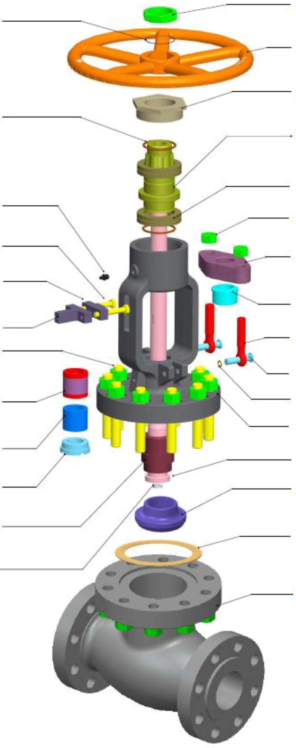
API 623 CAST STEEL GLOBE VALVE
Conventional Rising & Rotating Stem and Hand Wheel
Sample only, refer to as-built drawing as there are numerous designs or different sizes, classes, bonnet types and design standards. See Figure 11 for rising stem non rising hand wheel version.
GLOBE VALVES OS & Y - API623/BS1873/B16.34 Australian Pipeline Valve - Installation, Operation and Maintenance Manual 30
12
FIGURE
NO. PART NAME 1 Body 2 Bonnet 3 Disc 4 Seat Ring 5 Stem 6 Thrust Washer 7 Disc Nut 8 Seal Ring 9 Packing Ring 10 Gland 11 Gland Flange 12 Stem Nut 13 Handwheel 14 Packing 15 Spiral Wound Gasket 16 Bonnet Bolt 17 Bonnet Nut 18 Eyebolt 19 Nut 20 Pin 21 Screw 22 Washer 23 Handwheel Nut 21 23 22 13 12 19 11 10 14 9 8 18 20 2 5 7 6 3 4 15 16 17 1
APPENDIX B - CONT.
EXPLODED B.O.M. PRESSURE SEAL BONNET
TEST PRESSURE SHELL HYDRO SEAT HYDRO SEAT AIR BACKSEAT B16.34
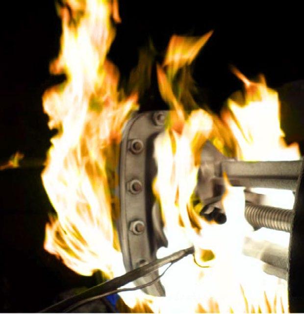
6.3 Ra/RTJ ASME B16.25 API 598/ISO 5208 API 623 & ASME B16.34 PAINT PP 07.002 NACE MR-01-75 & MR-01-03 (ISO 15156) FULL, S-BEND DESIGN GUIDED DISC API #16 316SS FULL STELLITE, FIRESAFE CERTIFIED API 607 PLUG TYPE, INVESTMENT CAST API 623 PATTERN CORROSION ALLOWANCE B16.34 6.0MM, CE PED CERTIFIED
TO FACE DIM. END CONNECTION END DIMENSION TEST & INSPECTION MARKING & PAINT OTHER REQ. PORT SIZE TRIM NOTES NOTES
BILL OF MATERIALS Weight
Torque Arm
FACE BODY TEMPERATURE MEDIUM Water, Oil, Gas ºC -46 TO 345 ºF -50 TO 653 Mpa Psi 0.55 80 Mpa Psi 4100 28.2 Mpa Psi Mpa Psi 38.4 5575 28.2 4100 4” 100 549 92 194 241.3 310 54.0 240 (1) DUAL CERTIFIED ASTM A216 WCC & WCB & A352 LCB (2) STEM SMOOTHNESS Ra ≤ 0.80 µ m PER API 623/API 600 (3) STUFFING BOX SMOOTHNESS Ra ≤ 3.2 µ m (SUPERIOR TO API 623) (4) GEARBOX, LOW FRICTION PACKING/STEM GUIDE, TORQUE ARM AND BODY GUIDED DISC FOR EASE OF OPERATION, ASSURED SHUT OFF AND LONG LIFE. ALSO, SUITABLE FOR HORIZONTAL INSTALLATION (PLEASE SPECIFY) (5) DIE FORMED SET INCONEL WIRE REINFORCED EXFOLIATED GRAPHITE PACKING,CHESTERTON 1622 (LOW FRICTION) FUGITIVE EMISSION CERTIFIED ISO 15848-1/API 622/API 624 & API 607 FIRESAFE CERTIFIED, CHEVRON & TEXACO CERTIFIED C/W CORROSION INHIBITOR (AS PER API 623). NON HARDENING & WILL NOT SHRINK OR ABSORB MOISTURE (6) REFER DRAWING. DIAMOND GEAR C/W GREASE NIPPLE, LOCK DEVICE, STEM PROTECTOR, 316SS INPUT SHAFT, POSITION INDICATOR MARKED WITH OPEN/CLOSED POSITION, HEAVY DUTY LOW RATIO FAST ACTING GEARBOX (5.2:1). V. GEARBOX PROTECTION LEVEL IP67 (7) DUAL CERTIFIED A105 (8) DUAL CONFORMING ASTM A193 B7M (9) DUAL LABLED APV AND FZV. API 623/API Q1 (10) TAPERED PLUG DISC (11) STEM GUIDE AND BODY GUIDED DISC API 623 AS SPECIFIED FOR THROTTLING APPLICATIONS (NEVER THROTTLE UNDER 20% STEM TRAVEL) (12) THICKNESS OF FACING MATERIAL ≥ 1.6MM AS PER API 623 (13) CONICAL SEAT AND TAPERED DISC FACINGS LAPPED ≤ Ra 0.4 µ m SUPERIOR TO API REQUIREMENTS AND SUPERIOR TO OTHER MANUFACTURERS (14) STELLITE HARDNESS 36 45 HRC (331 427 HB) (15) NON ROTATING RISING STEM, ROTATING STEM NUT. STEM & STEM NUT PRECISION ACME THREADS BURNISHED FINISH. ANTI-GALLING CORROSION RESISTANT STEM NUT, SERVICEABLE IN-LINE (16) COMPLIES WITH API 623 STUFFING BOX DEPTH, SIZE AND CLEARANCE FACTORS (17) CE PED LABLED n-d 8-3.0 OTHER OPTIONAL API 598 LP SEAT TEST ALSO PERFORMED, -46 º C IMPACT TESTED W H H1 520 965 224 N O PART NAME MATERIAL NOTES BODY ASTM A352 LCC2 SEAT ASTM A350 LF2 CL.1+STL#6 (7) (12) (13) (14) 3 DISC ASTM A350 LF2 CL.1+STL#6 (7) (10) (11) (12) (13) (14) BODY GUIDED 4 STEM ASTM A182 F316 (2) (11) (15) 5 DISC COVER ASTM A350 LF2 (7) 6 BONNET ASTM A350 LF2 (7) (16) 316SS OVERLAY 6A BACK SEAT SS316 OVERLAY 7 PRESSURE SEAL RING ASTM A182 F3168 UPPER BONNET YOKE ASTM A352 LCC (1) 9 UPPER GASKET ASTM A276 41010 BREECH LOCK NUT AISI 103511 PACKING (SET) GRAPHITE+INCONEL WIRE (3) (5) (16) CHESTERTON 1622 F.E. 12 YOKE SUPPORT FLANGE ASTM A352 LCC (1) 13 BOLT ASTM A320 L7M (8) 14 EYE BOLT ASTM A320 L7M (8) 15 NUT ASTM A194 7ML16 GLAND RING ASTM A276 31618 STEM GUIDE TORQUE ARM AISI 1035 (11) 19 SCREW ASTM A320 L7M (8) 20 STUD ASTM A350 L7M (8) 21 NUT ASTM A194 7ML22 STEM NUT ASTM A436 D-2C (15) AUSTENITIC-DI 23 GEARBOX ASSY-DIAMOND GEAR ASTM A216 WCB (4) (6) BA-2 LOCKABLE 24 RIVET 316SS25 NAME PLATE ASTM A240 316 (9) (17) 26 PACKING GASKET ASTM A182 31627 ASTM A194 7MLNUT 28 PACKING GLAND FLANGE ASTM A352 LCC29 ASTM A276 304POINTER (ASSY) 30 SCALE INDICATOR ASTM A276 304 OPEN/CLOSED 31 STEM PROTECTOR A3+ZP+EPOXY23 22 21 20 19 18 16 15 14 13 12 11 10 9 8 7 6 5 4 3 2 1 L n-d T 7.92 C R D O 25 6A 24 26 28 H H1 spot welded spot welded spot welded 31 WELDED SEAT
www.australianpipelinevalve.com.au
1027
GLOBE VALVES OS & Y - API623/BS1873/B16.34 Australian Pipeline Valve - Installation, Operation and Maintenance Manual 31
API 600 0206 API 6D 1473 API Q1 2345 API QR (9001) 2470 SHELL TAMAP MESC 2 STAR CHEVRON & BP APPROVED SIL 2 & 3 DUAL LABLED FZV LLOYDS FZPED & ATEX 2014/68/EU FZ-0343 API 607-7th & ISO 10497-3 Firesafe Certi ed SHELL MESC BH, C02 (-50ºC~400ºC) Fugitive Emission Prototype Certi ed APV DWG FRM
Dimensions in millimeters
N
DIMENSIONS (MM) & WEIGHT (KG) Inch DN
Example only, refer to as-built drawing. B.T.
APZ-FZV Globe Valve, Model 100FZAP129LUN-2PUMG-F NPS 4” (DN100) Class 1500, S-Bend T-Pattern, Guided Disc, Flanged, FP, PBOSY, GOP ORDER N O / DWG
O REV. APPROVED CHECKED DRAWN 1027 00
D L R C O T Australian Pipeline Valve
S.Q. C.C.
RATING DESIGN & MFG. PRESS-TEMP RATING
CL 2500 API 623 & ASME B16.34 (DUAL CONFORMS BS 1873) ASME B16.34 ASME B16.10 RFSF 3.2
The torque arm prevents stem movement which reduces wear on packing rings and enables better sealing as well as reducing torque. Non rotating stem, only the stem nut rotates. The arm also provides visual stem position indication and can be interfaced with position switches.
APPENDIX B - CONT.
EXPLODED B.O.M. SCREW DOWN NON RETURN
-
-
-
-
ASTM
www.australianpipelinevalve.com.au
BACKSEAT B16.34 BODY TEMPERATURE MEDIUM
Water, Oil, Gas ºC -29 TO 538 ºF -20 TO 1000 MpaPsi 0.55 80 MpaPsi 814
CL 300 BS1873/ASME B16.34/API600 ASME B16.34 ANSI B16.10 RFSF 3.2 6.3Ra ASME B16.5 API 598/ISO 5208 MSS SP-25 PAINT SPEC GGCFB-3 FULL PORT API #8 OPTIONAL HP/LP SEAT TEST PERFORMED (NOT MANDATORY AS PER API 598) INVESTMENT CAST
PORT SIZE TRIM NOTES OTHER
Example only, refer to as-built drawing.
GLOBE VALVES OS & Y - API623/BS1873/B16.34 Australian Pipeline Valve - Installation, Operation and Maintenance Manual 32
14 W 13 12 11 10 9 8 7 6 5 4 2 1 L T 1.6 N-d D R O 20 19 21 18 17 16 15 C Point welding H Top View Integral Disc Pin Guide Dimensions in millimeters Globe
RF,
ORDER
DWG
APPROVED
DIMENSIONS (MM) & WEIGHT
InchDND
H APV DWG FRM 196
B.T. S.Q. C.C. BILL OF MATERIALS NO. PART NAME MATERIALNOTES 1 BODY ASTM A216 WCB+STL#6
Weight RATING DESIGN & MFG. PRESS-TEMP RATING FACE TO FACE DIM. END CONNECTION END DIMENSION TEST & INSPECTION MARKING & PAINT OTHER REQ.
Valve, SDNR (Stop Check) BBOSY, NPS 10” (DN250) Class 300, Model No. 250 AP143LXUD -F
GOP, FP, WCB, Trim API #8
N O /
N O REV.
CHECKED DRAWN 196 00
(KG)
L RC O
Australian Pipeline Valve
-
5.7
Torque Arm The torque arm prevents stem movement which reduces wear on packing rings and enables better sealing as well as reducing torque. The arm also provides visual stem position indication and can be interfaced with position switches.
TEST PRESSURE SHELL HYDROSEAT HYDRO SEAT AIR T
MpaPsi MpaPsi 7.71125 5.7814
10”250 622
n-d W 254304.0387.44454616-ø29600682762
DISC & DISC GUIDE
A105+13Cr
4 STEM
GASKET (ENCAPSULATED)SS316+GRAPHITE
WOUND
BONNET ASTM A216 WCB
7 PACKING FLEXIBLE GRAPHITE (2)
REINFORCED 8 GLAND BUSH ASTM A276 410
9 GLAND FLANGE ASTM A216 WCB
10 EYEBOLT ASTM A193 B7
11 NUT ASTM A194 2H
12 PIN AISI 1025
13 STUD ASTM A193 B7
14 BEVEL GEAR ASSEMBLY
15 NAMEPLATE SS316
16 RIVET BRONZE
17 BLOCK ALLOY STEEL
18 SCREW ASTM A193 B719 BOLT ASTM A193 B720 NUT ASTM A194 2H
21 BACK SEAT ASTM A276 410
(1) STEM SMOOTHNESS Ra
STUFFING BOX SMOOTHNESS Ra
2
INTEGRAL
ASTM A276 410 (1) 5
SPIRAL
6
-
316
-
-
-
-
-
-
-
-
≤ 0.80 µ m (2)
≤ 3.2 µ m (SUPERIOR TO API 623)
APPENDIX C
FIGURE NUMBER SYSTEM - EXAMPLE 150FZAP125QTISN-9PBWG-FA
Bonnet gasket:
Blank Standard:- SS + GRP (BB), Pressure Seal Ring (PSB).
N/A:- (WB). A SS + PTFE B S31803 Spiral C PTFE
D SS + PTFE + GRP E Ring L Live Loaded Z Special
Stem packing: Blank Standard:- Graphite. N/A:- (Check Valves)
L Graphite + PTFE T PTFE F Fugitive Emission GRP
I Fugitive Emission PTFE J Special
Denotes special suffix - Packing/Gasket
Operator: Blank Handwheel or N/A A Actuator
G Gear H Hammer Blow Handwheel
End connection: Blank RF (B16.5) BA RF B16.47A (MSS SP44)
BB RF B16.47B (API 605) RJ RTJ BW Buttweld FF Flat Face
SP is special drilling UD Undrilled UM Unmachined for RF/RJ
Bonnet: Blank Bolted C Cryogenic H Pillar & Bridge L Low Temperature
P Pressure Seal S Bellows Sealed W Welded
Body material: - see page 5. (WCB is Blank)
Denotes special suffix - Body/Bonnet/Ends/Operator
Blank Non NACE N NACE
Blank Standard Configuration (Example Solid Wedge) A S Bend Globe D Globe-Stop Check
DG Globe - Stop Check Guided F Flexible Disc Gate J Slab Gate K Expanding Gate L Lever (Swing Check)
P Full Opening Swing Check (API 6D) Q Full Opening Piston Check (API 6D) R Right Angle S Parallel Slide
Y Inclined Bonnet Z c/w Spring
Denotes trim - Code & Modifier (see below)
Basic identifier number denoting valve class and valve type (As shown in catalogue)
Valve Size
TRIM CODES
GLOBE VALVES OS & Y - API623/BS1873/B16.34 Australian Pipeline Valve - Installation, Operation and Maintenance Manual 33
F - G BW PL 9 N - S QTI AP125 150 A
(1) Add modifier below if applicable. (2) As per trim code above. (3) Or Integral as per body. (4) API trim code #1 only (5) Geothermal trim. (6) Can be dual certified 316/316L. BODY SEAT SURFACE DISC SURFACE STEM BACK SEAT (STUFFING BOX) TRIM CODE (1) B Bronze Bronze Bronze Bronze C AL-Bronze AL-Bronze AL-Bronze AL-Bronze D Monel(1) Monel(1) Monel Monel E F51(1) F51(1) F51 F51 G F55(1) F55(1) F55 F55 H Hastelloy B(1) Hastelloy B(1) Hastelloy B Hastelloy B L F316(1)(6) F316(1)(6) F316(6) F316(6) M F316L(1) F316L(1) F316L F316L N Alloy 20(1) Alloy 20(1) Alloy 20 Alloy 20 P F304(1) F304(1) F304 F304 Q F304L(1) F304L(1) F304L F304L R Alloy 625(1) Alloy 625(1) Alloy 625 Alloy 625 V F53(1) F53(1) F53 F53 W F347(1) F347(1) F347 F347 Blank F6a/F6/410 F6a/F6/410 F6a/F6/410 F6a/F6/410 Z Special(1) Special(1) Special Special MODIFIER EN ENP ENP (2) (2) (3) GE(5) Stellite #6 Stellite #12 17-4 PH Stellite #6 I - - 17-4 PHM - - MonelT +PTFE Seat - -U Stellite Stellite (2) (2) (3) X (4) (4) (4) (4) XU Stellite (2) (2) (2) (3) Z - - Special -
APPENDIX C - CONT.
15
19
GLOBE VALVES OS & Y - API623/BS1873/B16.34 Australian Pipeline Valve - Installation, Operation and Maintenance Manual 34
FIGURE NUMBER SYSTEM -
MATERIAL CODE • BODY/BONNET
Suffix ASTM Spec. Material None A216 WCB Carbon Steel
A216 WCC Carbon Steel 1A A217 WC1 Carbon Moly 1/2% Mo 2 A352 LCC Low Carbon Steel 2B A352 LCB Low Carbon Steel 4 A351 CF3M Stainless with Molybdenum (low carbon) 5 A217 Gr. C5 5% Cr, 1/2% Mo 6 A217 Gr. WC6 1-1/4% Cr, 1/2% Mo 7 A217 Gr. WC9 2-1/4% CR, 1% Mo 8 A351 CF8 Stainless 18% Cr, 8% Ni 8A A351 CF3 Stainless 18% Cr, 8% Ni (low carbon) 8D A351 CF8C Stainless 18% Cr, 10% Ni & Cb 8M A351 CF8M Stainless with Molybdenum 9 A217 Gr. C12 Chrome Moly 9% Cr, 1% Mo 10 A352 LC1 Carbon Moly 1/2% Mo 11 A352 LC3 Low Carbon Steel (-101oC) 13 A351-CN7M Alloy 20 14 A890/A995-4A/CD3MN Duplex (F51)
BODY
MATERIALS
1
A995-6A/CD3MWCuN Super Duplex (F55)
Bronze Bronze B62/LG2/B148
AL-Bronze Aluminium Bronze 21 A995-5A/CE3MN Super Duplex (F53) 22 A296 M-35 Monel 23 A296 CW-12M Hastelloy C 24 A484 CU-5M CUC Inconel 825 25 A494 CY40 Inconel 600 26 A494 CW6MC Inconel 625 27 B367 GR.C2 Titanium (F2) 28 B367 GR.C3 Titanium (F3) 29 A358 LC4 Low Temp. 4-1/2% 30 A358 LC9 9% Nickel Steel 31 A358 CA6NM 18-1/2% Chromium, 32 A217 WC4 Nickel Chromium 33 A217 WC5 Nickel Chromium 34 A217 WC11 Chromium Molybdenum 35 A217 C12 Chromium Molybdenum 36 A217 C12A Chromium Molybdenum 37 A217 CA15 Chromium Steel 0 SPECIAL
20
APPENDIX D
WORKING PRESSURE & TEST MATRIX
CWP
CF8M/CF8/CF8C/CF3/CF3A/316/304/
GLOBE VALVES OS & Y - API623/BS1873/B16.34 Australian Pipeline Valve - Installation, Operation and Maintenance Manual 35
WCB/A105/LF2/LF3 (1.1) WC6/WC9/F5/F11/F22 (1.7/1.9/1.10) CLASS # CWP PSI BODY TEST X 1.5 PSI SEAT TEST X 1.1 PSI CWP MPA BODY TEST X 1.5 MPA SEAT TEST X 1.1 MPA CWP PSI BODY TEST X 1.5 PSI SEAT TEST X 1.1 PSI CWP MPA BODY TEST X 1.5 MPA SEAT TEST X 1.1 MPA 150 285 427.50 313.50 1.96 2.95 2.16 290 435.00 319.00 2.00 3.00 2.20 300 740 1110.00 814.00 5.10 7.65 5.61 750 1125.00 825.00 5.17 7.75 5.68 600 1480 2220.00 1628.00 10.20 15.30 11.22 1500 2250.00 1650.00 10.34 15.50 11.37 800 1975 2962.50 2172.50 13.61 20.41 14.97 2000 3000.00 2200.00 13.78 20.67 15.16 900 2220 3330.00 2442.00 15.30 22.94 16.83 2250 3375.00 2475.00 15.50 23.25 17.05 1500 3705 5557.50 4075.50 25.53 38.29 28.08 3750 5625.00 4125.00 25.84 38.76 28.42 2500 6170 9255.00 6787.00 42.51 63.77 46.76 6250 9375.00 6875.00 43.06 64.59 47.37
317/347 (2.1/2.2/2.5) 316L/304L/CN7M(Alloy 20)/M35-1/ M35-2/CF3/CF3M (2.3/3.4/3.17) CLASS # CWP PSI BODY TEST X 1.5 PSI SEAT TEST X 1.1 PSI CWP MPA BODY TEST X 1.5 MPA SEAT TEST X 1.1 MPA CWP PSI BODY TEST X 1.5 PSI SEAT TEST X 1.1 PSI CWP MPA BODY TEST X 1.5 MPA SEAT TEST X 1.1 MPA 150 275 412.50 302.50 1.89 2.84 2.08 230 345.00 253.00 1.58 2.38 1.74 300 720 1080.00 792.00 4.96 7.44 5.46 600 900.00 660.00 4.13 6.20 4.55 600 1440 2160.00 1584.00 9.92 14.88 10.91 1200 1800.00 1320.00 8.27 12.40 9.09 800 1920 2880.00 2112.00 13.23 19.84 14.55 1600 2400.00 1760.00 11.02 16.54 12.13 900 2160 3240.00 2376.00 14.88 22.32 16.37 1800 2700.00 1980.00 12.40 18.60 13.64 1500 3600 5400.00 3960.00 24.80 37.21 27.28 3000 4500.00 3300.00 20.67 31.01 22.74 2500 6000 9000.00 6600.00 41.34 62.01 45.47 5000 7500.00 5500.00 34.45 51.68 37.90 LCB (1.3) WCC/LCC (1.2) CLASS # CWP PSI BODY TEST X 1.5 PSI SEAT TEST X 1.1 PSI CWP MPA BODY TEST X 1.5 MPA SEAT TEST X 1.1 MPA CWP PSI BODY TEST X 1.5 PSI SEAT TEST X 1.1 PSI CWP MPA BODY TEST X 1.5 MPA SEAT TEST X 1.1 MPA 150 265 397.50 291.50 1.83 2.74 2.01 290 435.00 319.00 2.00 3.00 2.20 300 695 1042.50 764.50 4.79 7.18 5.27 750 1125.00 825.00 5.17 7.75 5.68 600 1395 2092.50 1534.50 9.61 14.42 10.57 1500 2250.00 1650.00 10.34 15.50 11.37 800 1975 2962.50 2172.50 13.61 20.41 14.97 - - - - -900 2090 3135.00 2299.00 14.40 21.60 15.84 2250 3375.00 2475.00 15.50 23.25 17.05 1500 3480 5220.00 3828.00 23.98 35.97 26.37 3750 5625.00 4125.00 25.84 38.76 28.42 2500 5805 8707.50 6385.50 40.00 59.99 44.00 6250 9375.00 6875.00 43.06 64.59 47.37 F5, F5a, F11, F22, F51, F53, F55, C5 CE8MN, 4A, 5A, 6A, CD3MN (1.3/1.17/2.8) CLASS # CWP PSI BODY TEST X 1.5 PSI SEAT TEST X 1.1 PSI CWP MPA BODY TEST X 1.5 MPA SEAT TEST X 1.1 MPA 150 290 435.00 319.00 2.00 3.00 2.20 300 750 1125.00 825.00 5.17 7.75 5.68 600 1500 2250.00 1650.00 10.34 15.50 11.37 800 2000 3000.00 2200.00 13.78 20.67 15.16 900 2250 3375.00 2475.00 15.50 23.25 17.05 1500 3750 5625.00 4125.00 25.84 38.76 28.42 2500 6250 9375.00 6875.00 43.06 64.59 47.37 AIR TEST 80 PSI 0.55 MPA
API598
5208)
shown as per ASME B16.34-2017. Test duration can be as per
(ISO
or API6D (ISO 14313)
WARRANTY
1. LIMITED WARRANTY: Subject to the limitations expressed herein, Seller warrants that products manufactured by Seller shall be free from defects in design, material and workmanship under normal use for a period of one (1) year from installation but in no case shall the warranty period extend longer than eighteen months from the date of sale. This warranty is void for any damage caused by misuse, abuse, neglect, acts of God, or improper installation. For the purpose of this section, “Normal Use”
means in strict accordance with the installation, operation and maintenance manual. The warranty for all other products is provided by the original equipment manufacturer.
2. REMEDIES: Seller shall repair or replace, at its option, any non-conforming or otherwise defective product, upon receipt of notice from Buyer during the Manufacturer’s warranty period at no additional charge. SELLER HEREBY DISCLAIMS ALL OTHER EXPRESSED OR IMPLIED WARRANTIES, INCLUDING, WITHOUT LIMITATION, ALL IMPLIED WARRANTIES OF MERCHANTABILITY AND FITNESS OR FITNESS FOR A PARTICULAR PURPOSE.
3. LIMITATION OF LIABILITY: UNDER NO CIRCUMSTANCES SHALL EITHER PARTY BE LIABLE TO THE OTHER FOR INCIDENTAL, PUNITIVE, SPECIAL OR CONSEQUENTIAL DAMAGES OF ANY KIND.BUYER HEREBY ACKNOWLEDGES AND AGREES THAT UNDER NO CIRCUMSTANCES, AND IN NO EVENT, SHALL SELLER’S LIABILITY, IF ANY, EXCEED THE NET SALES PRICE OF THE DEFECTIVE PRODUCT(S) PURCHASED DURING THE PREVIOUS CONTRACT YEAR.
4. LABOR ALLOWANCE: Seller makes NO ADDITIONAL ALLOWANCE FOR THE LABOR OR EXPENSE OFREPAIRING OR REPLACING DEFECTIVE PRODUCTS OR WORKMANSHIP OR DAMAGE RESULTING FROM THE SAME.
5. RECOMMENDATIONS BY SELLER: Seller may assist Buyer in selection decisions by providing information regarding products that it manufacturers and those manufactured by others. However, Buyer acknowledges that Buyer ultimately chooses the product’s suitability for its particular use, as normally signified by the signature of Buyer’s technical representative. Any recommendations made by Seller concerning the use, design, application or operation of the products shall not be construed as representations or warranties, expressed or implied. Failure by Seller to make recommendations or give advice to Buyer shall not impose any liability upon Seller.
6. EXCUSED PERFORMANCE: Seller will make a good faith effort to complete delivery of the products as indicated by Seller in writing, but Seller assumes no responsibility or liability and will accept no back-charge for loss or damage due to delay or inability to deliver, caused by acts of God, war, labor difficulties, accidents, inability to obtain materials, delays of carriers, contractors or suppliers or any other causes of any kind whatever beyond the control of Seller. Under no circumstances shall Seller be liable for any special, consequential, incidental, or indirect damages, losses, or expense (whether or not based on negligence) arising directly or indirectly from delays or failure to give notice of delay.
GLOBE VALVES OS & Y - API623/BS1873/B16.34 Australian Pipeline Valve - Installation, Operation and Maintenance Manual 36
Australian Pipeline Valve - Installation, Operation and Maintenance Manual NOTES
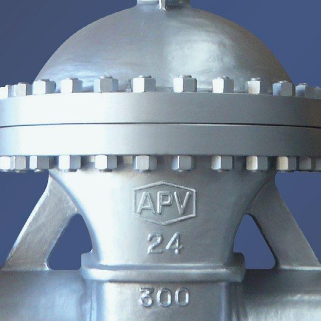
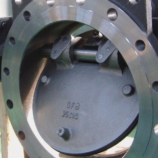
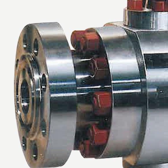
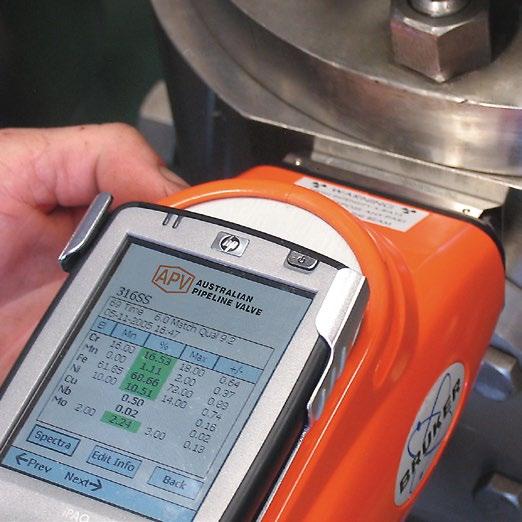
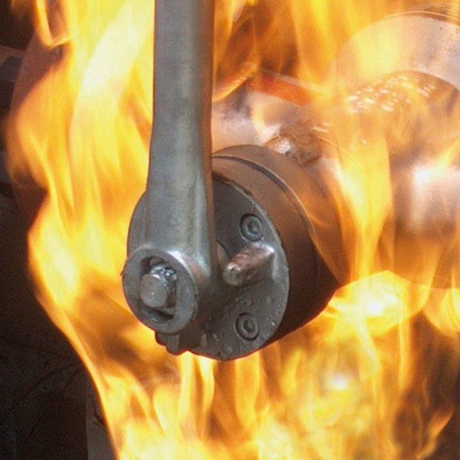
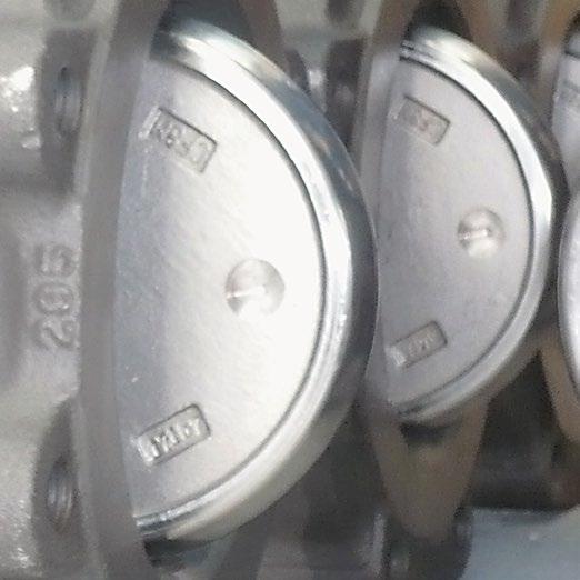
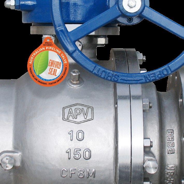
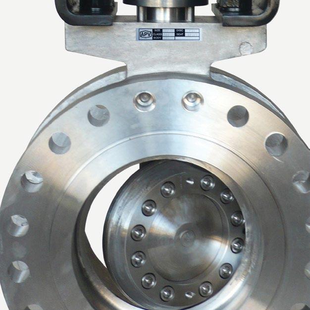

www.australianpipelinevalve.com.au AUSTRALIAN PIPELINE VALVE® HEAD OFFICE 70-78 Stanbel Road Salisbury Plain South Australia 5109 Telephone +61 (0)8 8285 0033 email: admin@australianpipelinevalve.com.au If you have any requirements in the field of valves, please contact us for a prompt response. Continuous development of Australian Pipeline Valve products may necessitate changes in the design or manufacture process. Australian Pipeline Valve reserves the right to effect any such changes without prior notice. © Australian Pipeline Valve 1990 - 2024 Edition LOCAL DISTRIBUTOR/AGENT IOM APV Globe Cast
