
www.australianpipelinevalve.com.au INSTALLATION, OPERATION & MAINTENANCE MANUAL FORGED CHECK VALVES SWING, PISTON & BALL API602/ISO 17561/ ASME B16.34
COMPLETE PRODUCT LINE
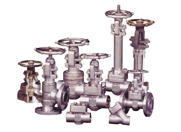
“Australian Pipeline Valve produces isolation, control and flow reversal protection products for severe and critical service media in utility, steam, pipelines, oil & gas and process industries. APV valves and pipeline products form the most competitive portfolio in the market.”
View our catalogues at www.australianpipelinevalve.com.au AUSTRALIAN PIPELINE VALVE BRAND RANGE - CATALOGUES APV FAMILY OF BRANDS RANGE - CATALOGUES
Oilfield Products Valves & Wellheads Gate, Globe & Check Valves - Forged Steel Plug Valves Lubricated, Sleeved & Lined Gate, Globe & Check Valves - Cast Steel Diamond Gear Gearboxes Flowturn Gate, Globe & Check Valves Flowturn Instrument Valves Flowturn Ball Valves Multiway & Deadman Flowturn Strainers & Sight Glasses Supercheck Wafer Check Valves Superseal Butterfly Valves Steamco Steam Valves Superseal Industrial Ball Valves TwinLok Tube Fittings Uniflo Check Valves
Actuators
Valves Floating & Trunnion Mounted Ball Valves Floating Small Bore Ball Valves Special Service Product Brochure Contact us for your local stockist/distributor
Torqturn
Ball
CHECK VALVES - SWING, PISTON & BALL - API602/ISO 17561/B16.34 Australian Pipeline Valve - Installation, Operation and Maintenance Manual 1 Introduction 2 Safety Information 3 Valve Identification 4 1.0 Installation 5-10 1.1 Installation positions 5-6 1.2 Preparation for installation 6 1.3 End connections 6-9 1.4 Post-installation procedures 10 2.0 Operation 10-11 2.1 Piston check/ball check valve 10 2.2 Swing check valve 10-11 3.0 Maintenance 11 4.0 Repairs 11-13 4.1 Repair instructions 11 4.2 Disassembly & gasket replacement 12 4.3 Valve internals disassembly instruction and repair 12-13 Appendix A - Body/bonnet bolting torques 15-16 Appendix B - Exploded B.O.M. (examples) 17 Appendix C - Part number system 18 Appendix D - Sample drawings 19-22 Appendix E - Working pressure & test matrix 23 Warranty 24 INDEX
The majority of this information is common knowledge to experienced valve users. When properly installed in applications for which they were designed, Australian Pipeline Valve (APV) valves will give long reliable service under normal conditions. This instruction manual is only a guide for installation and operation on standard service and covers general maintenance and minor repairs. An APV approved valve reconditioner should be used for reconditioning and major repairs.
Note
We recommend that this entire document be read prior to proceeding with any installation or repair. Australian Pipeline Valve and it’s parent company take no responsibility for damage or injury to people, property or equipment. It is the sole responsibility of the user to ensure only specially trained valve repair experts perform repairs under the supervision of a qualified supervisor.
RESPONSIBILITY FOR VALVE APPLICATION
The User is responsible for ordering the correct valves. The user is responsible for ensuring APV Valves are selected and installed in conformance with the correct pressure rating and design temperature requirements. Prior to installation, the valves and nameplates should be checked for proper identification to ensure the valve is of the proper type, material and is of a suitable pressure class and temperature rating to satisfy the applications requirements of the service application.
Do not use any valve in applications where either the pressure or temperature is higher than the allowable working values. Also valves should not be used in service media if not compatible with the valve material of construction, as this will cause chemical attacks, leakage, valve failure.
RECEIVING INSPECTION AND HANDLING
Valves should be inspected upon receipt to ensure:
- Conformance with all purchase order requirements.
- Correct type, pressure class, size, body and trim materials and end connections.
- Any damage caused during shipping.
The User is advised that specifying an incorrect valve for the application may result in injuries or property damage. Selecting the correct valve type, rating, material and connections, in conformance with the particular performance requirements is important for proper application and is the sole responsibility of the user.
CHECK VALVES - SWING, PISTON & BALL - API602/ISO 17561/B16.34 Australian Pipeline Valve - Installation, Operation and Maintenance Manual 2
INTRODUCTION
SAFETY INFORMATION
The following general safety information should be taken into account in addition to the specific warnings and cautions specified in this manual. They are recommended precautions that must be understood and applied during operation and maintenance of the equipment covered in this I.O.M.
To avoid injury, never attempt disassembly while there are pressures either upstream or downstream. Even when replacing gaskets, caution is necessary to avoid possible injury. Disassemble with caution in case all pressures are not relieved.
To prevent valve bending, damage, inefficient operation, or early maintenance problems, support piping on each side of the valve. Warning, certain gases and fluids could cause damage to human health, the environment or property hence the necessary safety precautions to prevent risk should be taken.
This manual provides instructions for storing, general servicing, installation and removal of check valves. APV and it’s resellers refuse any liability for damage to people, property or plant as well as loss of production and loss of income under any circumstances but especially if caused by: Incorrect installation or utilisation of the valve or if the valve installed is not fit for intended purpose. It is the sole responsibility of the user to ensure the valve type and materials are correctly specified.
DURING OPERATION TAKE INTO ACCOUNT THE FOLLOWING WARNINGS:
a- Graphite body gaskets (where applicable) are very brittle, any compacting, twisting or bending should be avoided.
b- The valve’s internal parts (disc/stem/hinge pin/seats/gaskets/seals, etc.) shall be handled with care avoiding scratches or surface damage.
c- All tools and equipment for handling the internal parts shall be soft coated, or else take care.
d- Valves can be fitted with gaskets or seals in PTFE, Buna, Viton, etc., hence high temperatures and some cleaning fluids may damage sealing components.
For all operations make reference to position number on part list of the applicable drawing.
CHECK VALVES - SWING, PISTON & BALL - API602/ISO 17561/B16.34 Australian Pipeline Valve - Installation, Operation and Maintenance Manual 3
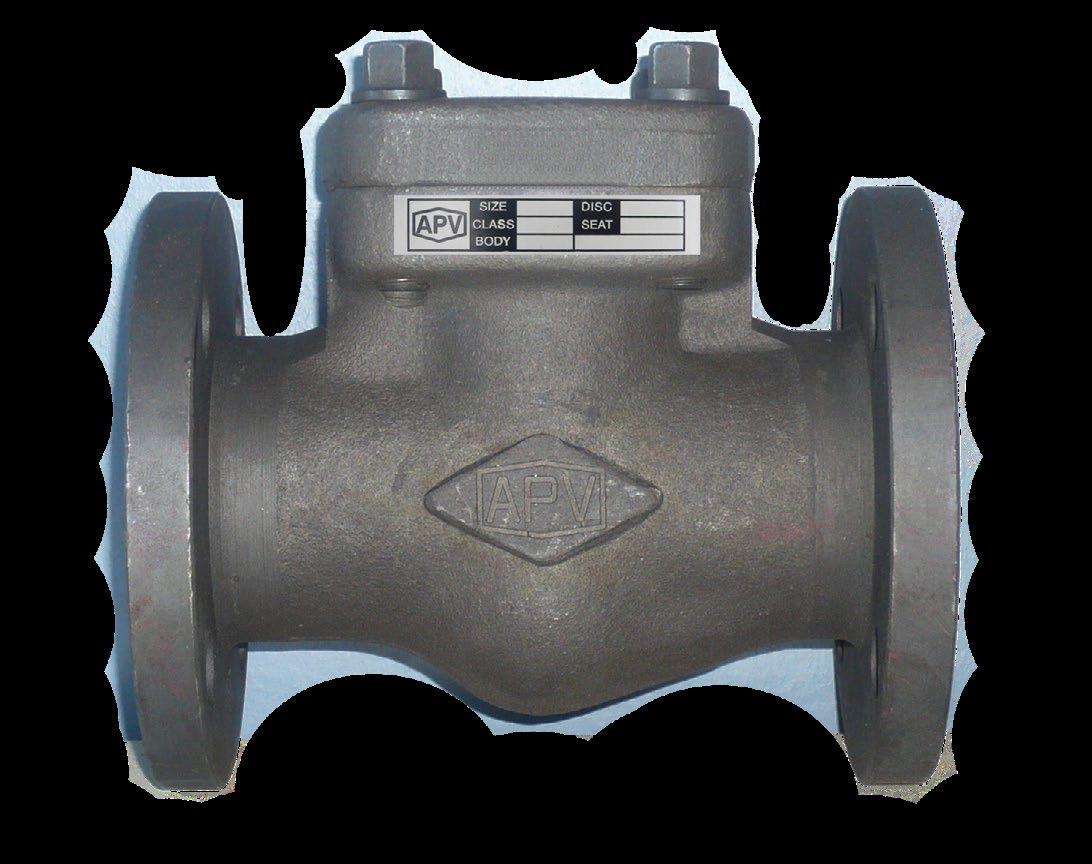
VALVE IDENTIFICATION
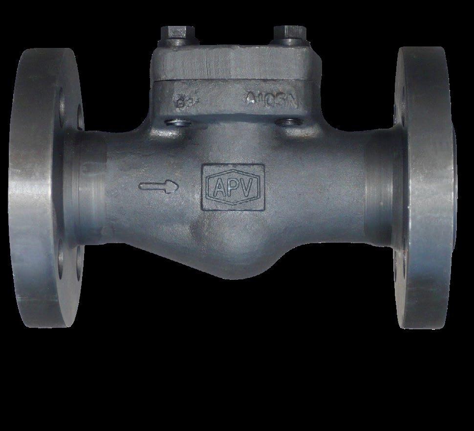
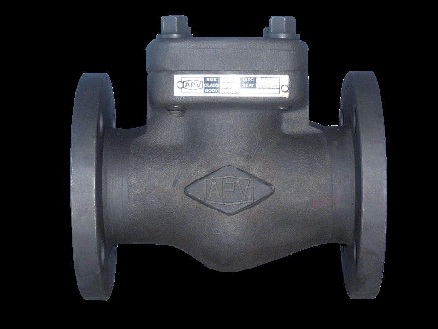
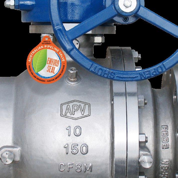
Each APV valve is identified with a nameplate, which is placed over the handwheel and secured with the hand wheel nut on gate and globe valves, and riveted to the cover on check valves. Below is an example.
When performing any work, ordering spare parts, or requesting technical support, please refer to this tag. The serial number, the part number and numbers on the side of the valve body are keys to proper valve identification.
CHECK VALVES - SWING, PISTON & BALL - API602/ISO 17561/B16.34 Australian Pipeline Valve - Installation, Operation and Maintenance Manual 4
TYPE CLASS BODY ENDS SIZE STEM PKG DISC GASKET SEAT CWP@38ºC MAX TEMP API 602 ASME B16.34 9 10 11 12 13 14 15 8 8 7 6 5 4 3 2 1 No. Figure Number Code Description 1 Serial number Serial/batch numbers 2 Type The as-built valve type 3 Body Material Shell material (e.g. body, bonnet) 4 Stem Stem material (e.g. A105, WCB, F51, CF8M, etc.) 5 Disc Closure member base material + overlay 6 Seat Seat base material (+ overlay if applicable) 7 MAX Temp. Maximum temperature 8 Standard Applicable design codes 9 Model number APV valve figure number which delineates the as-built valve type, body, trim, features, packing, NACE, etc. Refer figure number system in Appendix B 10 Class Rated pressure class 11 Ends End connections 12 Size Nominal pipe size 13 PKG Stem packing (e.g. GRP, GRPF, PTFE, X750, 316 spring) 14 Gasket Bonnet gasket (e.g. SW316, 316 ring, PTFE) 15 CWP @ 38ºC Cold working pressure temperature * NACE MR0175 Identifies corrosion resistance * NACE is indicated by a separate NACE tag.
1.0 INSTALLATION
Piping should be properly aligned and supported to reduce mechanical loading on the end connections.
1.1 INSTALLATION POSITIONS
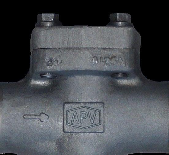
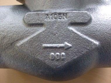
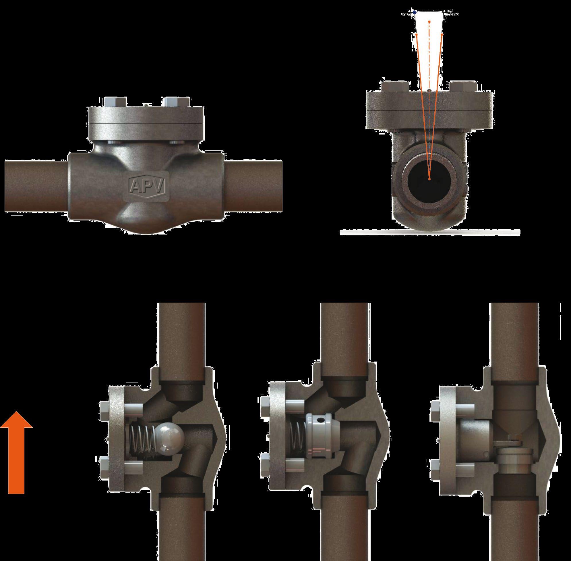
Check valves are unidirectional and have the direction of flow indicated on the valve body, as per Figure 1.
Australian Pipeline Valve piston and ball check valves are recommended for use in horizontal lines with bonnet facing up. Spring loaded APV ball check valves and y-type piston check valves can also be used in vertical line, see Figure 2.
Check valves must be fitted in horizontal pipe runs with the cover facing vertically upward. Variance to either side of the vertical axis must not exceed five (5) degrees. Swing-check valves and spring-loaded check valve designs can be positioned in vertical pipe runs with upward flow.
Check valves must not be installed in a vertical down flow pipe run or in a horizontal pipe run with the cover in the vertical down position. Always install valves in the direction indicated by the flow arrow stamped on the body. Note
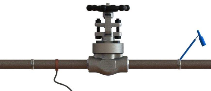
Flow disturbances caused by the system components (e.g. pipe fittings, discharge of pumps, etc.) can lead to valve chatter, which can cause rapid wear of seats and trim and ultimately lea to valve malfunction. APV recommends that a sufficient distance be maintained between the check valve and any component that can cause flow disturbance as follows:
a) System components that create flow disturbance - examples are pumps, fittings and valves. When installing a check valve near system components, APV recommends a minimum of 10 pipe diameters of straight pipe between the upstream system components and the inlet of the check valve and a minimum of 2 pipe diameters of straight pipe between the downstream system components and the outlet of the check valve.
b) Pipe bends and transitions - examples are elbows, tees, branch connections and reducers. APV recommends a minimum of 10 pipe diameters of straight pipe between the upstream system component and the inlet of the check valve and a minimum of 4 pipe diameters of straight pipe between the downstream component and the outlet of the check valve.
CHECK VALVES - SWING, PISTON & BALL - API602/ISO 17561/B16.34 Australian Pipeline Valve - Installation, Operation and Maintenance Manual 5
FIGURE 1
Spring loaded piston check valves are recommended for reciprocating compressor service in which a history of noisy check valve operation has been experienced.
Australian Pipeline Valve swing check valves may be installed in horizontal lines or vertical lines where the direction of flow (see Figure 1) as indicated on the valve body is upwards.
Note - Only spring loaded ball check valves, spring loaded piston check valves and swing check valves may be installed in vertical runs of pipe. Flow must be upward.
Australian Pipeline Valve - Installation, Operation and Maintenance Manual 6
CHECK VALVES - SWING, PISTON & BALL - API602/ISO 17561/B16.34
Maximum Rotation
Spring Loaded Ball Check Spring Loaded Piston Check Swing Check
FIGURE 2
CHECK VALVE POSITIONING
10° MAX
Horizontal Line with Flow Arrow Flow
Direction
1.2 PREPARATION FOR INSTALLATION
• Remove protective end caps or plugs and inspect valve ends for damage to threads, socket weld bores or flange faces.
• Thoroughly clean adjacent piping system to remove any foreign material that could cause damage to seating surfaces during valve operation.
• Verify that the space available for installation is adequate to allow the valve to be installed.
1.3 END CONNECTIONS
1.3.1 Threaded Ends
Check condition of threads on mating piping.
Apply joint compound to the male end of joint only. This will prevent compound from entering the valve flow path.
1.3.2 Flanged Ends
Check to see that mating flanges are dimensionally compatible with the flanges on the valve body and ensure sealing surfaces are free of debris.
Install the correct studs and nuts for the application and place the gasket between the flange facings.
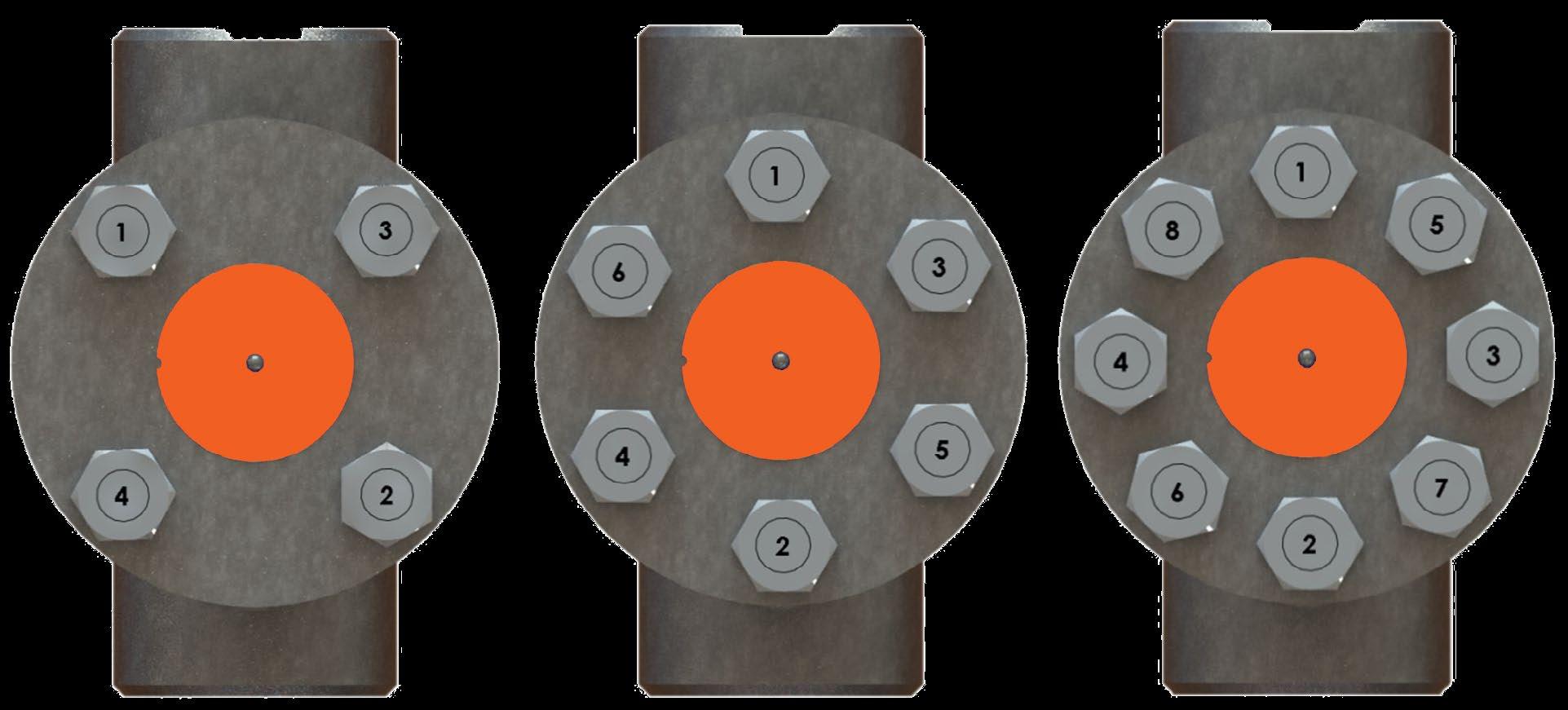
Stud nuts should be tightened in an opposing cris-cross pattern in equal increments to ensure even gasket compression. See Appendix A, Table A.
1.3.3 Socket weld Ends
Remove all debris, grease, oil, paint, etc., from the pipe that is to be welded into the valve and from the valve end connections.
Insert the pipe into the valve end connection until it bottoms out in the socket weld bore. Withdraw the pipe 1.59mm (1/16”) so that a gap remains between the pipe and the bottom of the socket weld bore to prevent cracks (ASME B1.11). Tack the pipe into the valve and complete the fillet weld.
1.3.4 Buttweld Ends
Clean the weld ends as necessary and weld into the line using an approved weld procedure. Make sure the pipe and valve body material given on the nameplate or valve body is compatible with the welding procedure. (Refer compatibility cross reference chart at the APV website for equivalent pipe, valve & fitting grades).
1.3.5 Valve Installation by Welding
Unless the valve contains PTFE packing and/or gasket, leave valves assembled during installation,
CHECK VALVES - SWING, PISTON & BALL - API602/ISO 17561/B16.34 Australian Pipeline Valve - Installation, Operation and Maintenance Manual 7
welding and post-weld heat treatment. This will prevent the valve seat from floating or distorting during the process. After welding completion, open the valve and flush line to clean out any foreign matter.
Valves under 40mm (1.5”) fitted with a PTFE or elastomer bonnet gasket must be disassembled for installation as the welding temperature can adversely affect the PTFE components. Remove the bonnet and bonnet gasket and match mark each component during disassembly for proper reassembly. If you do not disassemble valves it will be the responsibility of the operator to ensure valves are kept cool during welding and then post-weld testing of the valve should be performed. Larger size valves over 40mm (1 1/2”) NB are less likely to transmit heat to bonnet gasket during welding but still care should be taken.
The responsibility for welding of the valves into piping systems is that of those performing the welding. Refer to ASME B31.1, B31.3 etc. Written welding procedures covering all attributes of the process and materials to be welded shall be in accordance with Section IX of the ASME Boiler and Pressure Vessel Code and any additional requirements from the applicable piping code including any possible necessary localised post weld heat treatment depending on material specifications.
APV forged globe, piston and ball check valves do not run the risk of seat loosening during welding due to the fact that they are supplied with integral Stellite body seats.
Subsequent to welding, clean and inspect the finished weld(s) and, if necessary, repair any defects using a qualified weld repair procedure. In addition, cycle the valve open-closed to check for proper operation, making sure no binding has occurred due to the weld heat.
Special trim options and body materials such as valves with PTFE packing/soft seat/special seals/ and gaskets that have maximum temperature limits less than the valve, may require special welding and heat treatment considerations which are not included herein.
CHECK VALVES - SWING, PISTON & BALL - API602/ISO 17561/B16.34 Australian Pipeline Valve - Installation, Operation and Maintenance Manual 8
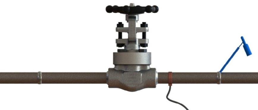
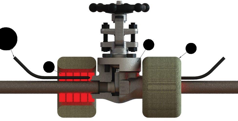
1.3.6 Post Weld Heat Treatment (PWHT)
The recommended method of PWHT is via local ceramic resistance heaters, individually monitored with thermocouples. Thermocouples are attached to the weld or welds. Properly sized ceramic heaters are wrapped around the weld area, extending approximately 6.35mm (1/4”) past the weld on the valve side. Do not wrap the valve body with a heating element. See Figure 1 for details. Wrap flexible insulation around valve ends, extending approximately 12.5mm (1/2”) past the valve on the valves side. It is not recommended to wrap the entire valve body with insulation. Prior to heat input close the valve completely, then open the valve approximately 1.58mm (1/16”) of a turn after the handwheel slack is run out. This very slight opening will allow the trim components to expand during the thermal cycle. Following PWHT, inspect the valve for smooth operation by cycling open and closed. If possible, perform a seat closure pressure test prior to service operation.
CHECK VALVES - SWING, PISTON & BALL - API602/ISO 17561/B16.34 Australian Pipeline Valve - Installation, Operation and Maintenance Manual 9 FIGURE 3 INCORRECT Arcing can occur across close tolerance areas of valve due to ground strap location. Ground Strap Ground Strap Welding CORRECT Ground strap is positioned before the valve Welding WELD SET UP
4 4 3 2 1 ITEM DESCRIPTION 1 THERMOCOUPLE 2 VALVE 3 FIBRE INSULATION 4 CERAMIC HEATERS
FIGURE
POST WELD HEAT TREATMENT
1.4 POST-INSTALLATION PROCEDURES
After installation, the line should be cleaned by flushing to remove any foreign material. When caustics are to be used to flush the line, additional flushing with clean water is required. The valve should be opened and closed after installation to ensure proper operating function.
With the line pressurised, check the valve end connections, body to bonnet/cover joints and external plugs for leaks.
2.0 OPERATION
The check valve operation is automatic and requires no assistance. When the flow exerts sufficient pressure against the disc to overcome the disc’s weight, the disc allows the flow to continue through the piping system. As pressure decreases, the disc lowers until it’s own weight forces it to seat. This prevents the possibility of a reversal in the flow. Piston and ball check valves should not be used in applications where rusting or rust particles are present or anticipated. Swing check valves are more tolerant for applications of this nature.
Metal seated check valves (piston, ball and swing) are not zero leak devices and may “seep” in service. This type of valve should always be backed up with an isolation valve (either gate or ball valve). Check valves are designed to prevent reverse flow. Leakage rates for check valves with metal-to-metal seats are dependant on the amount of back pressure and the viscosity of the flowing medium. Soft seat check valves can offer improved leak tightness provided there is sufficient back pressure. Check valves should not be used in gas or low back pressure liquid applications if zero leakage is desired.
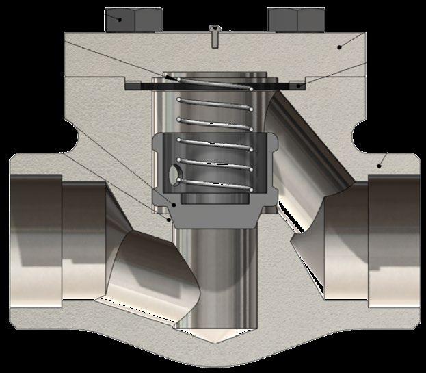
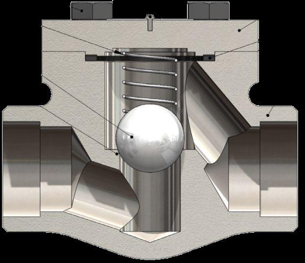
2.1 PISTON CHECK/BALL CHECK VALVE
A typical bolted bonnet piston check and ball check are shown in Figure 7; an exploded view is shown in Appendix B. The bodies (8) of the piston check valve and the ball check valve are of the same labyrinth design as that of the globe valve. The barrier of flow is a free moving piston (6) that is guided by the body (8) or a free moving ball (10) that is guided by the bonnet (4). The piston check and ball check also have an integral seat (7) (renewable seats also an option), against which either the piston (6) or the ball (10) seat to provide stoppage of flow. The piston (6) or ball (10) drop into the seat (7) by gravity during no-flow conditions and open by fluid pressure on the upstream side (from underneath the piston (6) or ball (10). Reversal of fluid flow forces the piston (6) or ball (10) back into the seat (7) which stops the flow.
The piston and ball check valves are designed for horizontal service; however, these valves can be equipped with an internal spring (9) which allows the valve to be used in vertical up service, as shown in Figure 2.
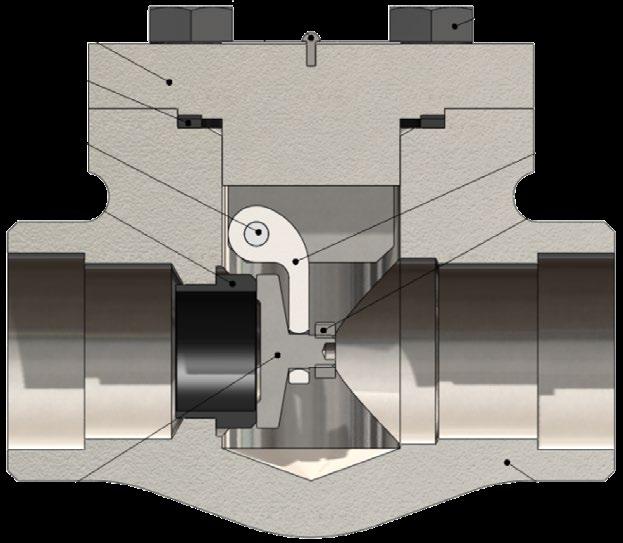
2.2 SWING CHECK VALVE
A typical bolted bonnet swing check valve is shown exploded view in Appendix B. The swing check valve is a straight-through flow check valve equipped with a disc (7) which rests against the seat (9) under
CHECK VALVES - SWING, PISTON & BALL - API602/ISO 17561/B16.34 Australian Pipeline Valve - Installation, Operation and Maintenance Manual 10
no-flow conditions. The seat (9) is pressed into the valve body (11) and is of the removable design. A hinge (5) supports the disc (7) from a hinge pin (8) which is set in the valve bonnet (6). The supporting hinge (5) allows the disc (7) to swing freely away from the seat (9) because of the flow pressure being exerted upon the disc’s upstream side. A reversal of fluid flow exerts pressure on the downstream side of the disc (7) forcing it against the seat (9) and stopping the flow.
A check valve should not be used as a primary means of isolation for any application because a check valve may not provide a leak-tight (no through leakage). Only gate or globe valves should be used for isolation.
3.0 MAINTENANCE
No periodic maintenance is necessary unless special external accessories are fitted.
4.0 REPAIRS
Proper safety equipment and apparel should be worn when preparing to service a valve. Observe the following general warnings:
• A valve is a pressurised device containing energised fluids and should be handled with care.
• Valve surface temperature may be dangerously too hot or too cold for skin contact.
• Upon disassembling, attention should be paid to the possibility of releasing dangerous and or ignitable fluids.
• Adequate ventilation should be available for service.
4.1 REPAIR INSTRUCTIONS
Due to the relatively low replacement cost of small diameter standard carbon steel valves especially under 80 NB (3”), it is usually less expensive to replace the complete valve than to have maintenance personnel effect repairs. Generally, the only viable repairs are replacement of bonnet gasket. However, see Section 4.2 and 4.3 below for further extraordinary repairs. Always replace the bonnet gasket whenever a valve is disassembled. Gasket seating surfaces should be scraped clean (avoid radial marks). Bonnet bolts should be tightened in a diagonal pattern at several different increasing torque settings in accordance with the recommended torque value (see table Appendix A, Table A and Figure 6).
CHECK VALVES - SWING, PISTON & BALL - API602/ISO 17561/B16.34 Australian Pipeline Valve - Installation, Operation and Maintenance Manual 11
4.2 DISASSEMBLY & GASKET REPLACEMENT
Before disassembling:
1. Check that the line is in a complete shut down phase, then remove the valve from pipeline.
2. Pre-order all necessary spare parts and joining gaskets.
3. Put identification markings on valve body, disc and bonnet. This helps to avoid mismatching of parts at the time of re-assembly.
4. If the bolts and nuts are too tight, apply deep penetrating oil and then unscrew.
Disassembly:
1. Disassemble all cover bolts and nuts.
2. Gently break the seal with a lever, gradually lifting the bonnet flange at intervals 360° around the bonnet.
3. Clean gasket surface areas, replace gasket and refit bonnet as detailed in 4.1 above.
4. ‘Pressure seal’ valves use a proprietary gasket.
4.3 VALVE INTERNALS DISASSEMBLY INSPECTION AND REPAIR
1. Check that the (where applicable) hinge, nut and pin are in good condition and firmly connected. Replace damaged parts as necessary.
2. For swing check valves, lift and remove the disc hinge assembly. Movement should be free and not hindered by any malfunction of the hinge pin. Where disc travel is not sufficiently smooth, remove plugs or blind flanges and then remove hinge pin. Check surface for seizure or scraping marks. If marks are deeper than 1.5mm (1/16”), re-machine hinge pin and reassemble hinge pin and reassemble. If defect depth is greater than 1.5mm (1/16”), a new hinge pin is necessary. When reassembling hinge pin, it is recommended that the disc be removed by loosening the nut. For piston check or ball check valves, if there is a spring ensure it is functioning properly and is sufficiently energised. The spring should hold the disc/ball tightly against the seat no matter what position the valve is in.
3. When leakage is due to deterioration of seal surfaces caused by corrosion, erosion or foreign substances, it must be determined whether the disc or seal seat are the cause. Where special soft seat inserts are supplied, consult APV.
a) Deterioration of disc surfaces:
Swing check valves: - Disassemble disc by removing nut and washer. (Ball/Piston check valves have a free floating disc). Repair surface by grinding and relapping using a fine grade abrasive paste.
b) Deterioration of seat seal surfaces:
When seal surfaces are damaged and defects are confined to a small area but are not deeper than 0.4mm the seal surface can be relapped. For smaller sizes the recommended method is to use a cast iron strap with an outside diameter matching the valve’s raceway. If the seat surfaces cannot be relapped an APV approved repairer will decide if the surface has to be reground/re-machined or replaced. When defects are deeper than 0.4mm and found on the entire surface, re-metallising or a new seat is required. For threaded-in seats it is recommended that an anti seizure compound be used when installing the replacement seat to make threading it in the body easier.
- SWING, PISTON & BALL - API602/ISO 17561/B16.34 Australian Pipeline Valve - Installation, Operation and Maintenance Manual 12
CHECK VALVES
Always be sure that the valve is de-pressurised and isolated prior to performing any maintenance work. Remove any dangerous fluids from valve before commencing maintenance.
Check valves do not require lapping fixtures as the bore of the valve body serves as a guide. On ball check valves the rolling action of the ball retains seating surfaces in good condition until ball size or ball guide is worn and replacement parts are needed.
After lapping, it is recommended that the surface of the seat and disc be checked for proper contact using the marking blue. Coat the seats with marking blue, and tightly screw the disc into the seats. Unscrew the disc, and examine to make sure there is continuous contact between the sealing surfaces of the disc and body seat.
CHECK VALVES - SWING, PISTON & BALL - API602/ISO 17561/B16.34 Australian Pipeline Valve - Installation, Operation and Maintenance Manual 13
Typical Forged Bolted Piston Check Valve Exploded View
1. Seat
The seat ensures a stable shut off. The seat is precision ground for optional seating.
2. Cover Gasket
The cover gasket creates a leak-proof seal between the bonnet and the body.
3. Piston
Piston is machined to the tightest tolerances to ensure trouble free shut off and cycling.
4. Spring
The spring is precision made and loaded for precise pressures.
5. Cover
The cover allows access to internal components.
6. Cover Studs
The cover studs secure the bonnet to the body.
7. Body
Forged steel bodies provide low resistance flow and optimum strength and performance.
Spring O-ring
Body Seat Overlay
Body
Elastomer Seat Insert Option (Piston Check Valves)
Bolted Cover (Spiral Wound Type)
Sample only refer to as built drawing as there are numerous styles and designs also vary depending on size & class.
CHECK VALVES - SWING, PISTON & BALL - API602/ISO 17561/B16.34 Australian Pipeline Valve - Installation, Operation and Maintenance Manual 14
FIGURE 5 7 2 1 3 4 5 6
Bolted Cover (Ring Type Joint)
Welded Cover (Full Penetration Welding)
APPENDIX A
INDICATIVE BONNET BOLTING (BOLTED BONNET) TORQUE NM
Note:
(1) Different body gaskets may require slightly different torques.
(2) Torque tolerance ±10%.
(3) For temperatures above 750°F (400°C) use 75% of the torque values. In high temperature services, there is a possibility of creep in the bonnet studs. Regular checking of the bonnet - studs for tightness, would help prevent leakage through the bonnet gasket.
(4) Above torque values are with the bolts lubricated.
(5) Values above are based on 30,000 psi (206.85 Mpa) bolting stress and lubricated with heavy graphite and oil mixture or a copper based anti-seize grease.
(6) Do not exceed by more than 25% of values stated when emergency torquing is required.
(7) All bolts shall be torqued in the pattern as shown in Figure 6 on next page to ensure uniform gasket loading.
(8) Optimum torque can vary depending on type of body gasket but do not increase torque more than 10% above those shown.
(9) Consult us for other bolt material.
(10 Most B8M and B8 bolts class 2 can be tightened to a higher torque.
Note
For ‘pressure seal’ bonnet consult APV for torques (where bolting is applicable). Bolt tensions shown must be decreased by 25% when other or no lubrication used. Non lubricated bolts can have an efficiency of less than 50% the torque of values stated. Indicative torques are shown only, different body gasket systems, different sizes & classes, etc., will have different torque requirements. Furthermore, other stud grades can have much lower torques depending if class 1 or class 2 and or above variables.
CHECK VALVES - SWING, PISTON & BALL - API602/ISO 17561/B16.34 Australian Pipeline Valve - Installation, Operation and Maintenance Manual 15
TABLE A Stud Size UNC Stud Size Metric Maximum Body-Bonnet Bolt Torque All bolt materials with min. yield stress @ room temp. > 60ksi (>400MPa) Example B7 All bolt materials with min. yield strength @ room temp. ≤ 60ksi (≤400MPa) Example B8/B8M Class 1 (10) Ft-Lb N-m Ft-Lb N-m 3/8 UNC M10 20 30 11 16 1/2 UNC M12 50 70 27 37 9/16 UNC M14 70 95 38 50 5/8 UNC M16 100 140 50 70 3/4 UNC M20 170 230 90 125 7/8 UNC M22 270 370 145 200 1 UNC M24 400 550 215 300
BOLT TIGHTENING SEQUENCE EXAMPLE
CHECK VALVES - SWING, PISTON & BALL - API602/ISO 17561/B16.34 Australian Pipeline Valve - Installation, Operation and Maintenance Manual 16
APPENDIX A - CONT.
6
FIGURE
EXPLODED BILL OF MATERIALS (EXAMPLES)
Typical example only refer to as-built drawing
CHECK VALVES - SWING, PISTON & BALL - API602/ISO 17561/B16.34 Australian Pipeline Valve - Installation, Operation and Maintenance Manual 17
APPENDIX B
FIGURE 7 ITEM DESCRIPTION 1 RIVET 2 NAME PLATE 3 BOLTS 4 BONNET 5 GASKET 6 PISTON 7 INTEGRAL SEAT 8 BODY 9 SPRING* 10 BALL * The spring will be supplied on request 4 5 1 3 2 6 7 8 9 PISTON CHECK 4 5 1 3 2 10 7 8 9 BALL CHECK ITEM DESCRIPTION 1 RIVET 2 NAME PLATE 3 B/B BOLTS 4 B/B GASKET 5 HINGE 6 BONNET 7 DISC 8 HINGE PIN 9 SEAT 10 DISC NUT 11 BODY 4 5 1 3 2 10 7 8 9 11 6
SWING CHECK
APPENDIX C
Part Number System
A B C D E Type
Class Connection Body Material Type
F Trim
- CLASS
G - NACE
Blank = NON NACE N = NACE
H - BORE
R = STANDARD BORE F = FULL BORE Z = SPECIAL BORE
DASH
- = SPECIAL SUFFIX
I - SPECIAL
BL = BELLOWS SEALED
- I Dash Special
Nace
(EXAMPLE) GLBBSW80ADR-5 : GLOBE VALVE, BOLTED BONNET, SOCKET WELDED, 800LBS, A105N, MONEL TRIM, NON NACE, STANDARD BORE, RING GASKET G H Bore
GA GATE SOLID WEDGE
GF GATE FLEX WEDGE
GP GATE PARALLEL SLIDE
GL GLOBE
GS GLOBE SDNR (STOP CHECK)
GY Y-TYPE GLOBE (IN LINE)
YS Y-TYPE GLOBE SDNR
GN NEEDLE POINT GLOBE
PC PISTON (LIFT) CHECK
BC BALL CHECK
HC BALL HEAD PISTON (LIFT) CHECK
SC SWING CHECK
AG RIGHT ANGLE GLOBE
AY RIGHT ANGLE GLOBE Y-TYPE
ZZ SPECIAL
BB
WB
PS
BL
Section
I
NP
FF
UD
RJ
RU
ZZ
J K Bonnet Gasket Stem Packing
C ASTM A182-F5
E ASTM A182-F11
G ASTM A182-F304
H ASTM A182-F304L
J ASTM A182-F316
K ASTM A182-F316L
L ASTM A350-LF2
M ASTM A182-F304/F304L*
N ASTM A182-F316/316L*
P ASTM A182-F321
Q ASTM A182 F51
R ASTM A182 F55
S ASTM A182 F53
T ASTM A350-LF3
Z SPECIAL
*Dual Certified
TRIM CODES
CR = CRYOGENIC
EX = EXTENDED BONNET
LP = LONG PATTERN
SP = C/W SPRING
PT = PTFE SEAT
ZZ = OTHER SPECIAL
J - BONNET GASKET
Blank Standard: SS Spiral + GRP (BB), Pressure Seal Ring (PSB).
1 SS Spiral + PTFE
2 S31803 Spiral
3 PTFE
4 SS Spiral + PTFE + GRP
5 Ring
9 Special
K - STEM PACKING
Blank Standard: Graphite.
N/A- (Check Valves)
L Graphite + PTFE
T PTFE
F Fugitive Emission GRP
P Fugitive Emission PTFE
Z Special
BODY SEAT SURFACEDISC SURFACESTEM BACK SEAT TRIM CODE (1) B Bronze Bronze Bronze Bronze C AL-BronzeAL-BronzeAL-BronzeAL-Bronze D Monel(1) Monel(1) Monel Monel E F51(1) F51(1) F51 F51 G F55(1) F55(1) F55 F55 H Hastelloy B(1) Hastelloy B(1) Hastelloy BHastelloy B L F316(1)(6) F316(1)(6) F316(6) F316(6) M F316L(1) F316L(1) F316L F316L N Alloy 20(1) Alloy 20(1) Alloy 20Alloy 20 P F304(1) F304(1) F304 F304 Q F304L(1) F304L(1) F304L F304L R Alloy 625(1) Alloy 625(1) Alloy 625Alloy 625 V F53(1) F53(1) F53 F53 W F347(1) F347(1) F347 F347 Blank F6a/F6/410F6a/F6/410F6a/F6/410F6a/F6/410 Z Special(1) Special(1) Special Special MODIFIER EN ENP ENP (2) (2)(3) GE(5) Stellite #6Stellite #1217-4 PHStellite #6 I - - 17-4 PHM - - MonelT +PTFE Seat - -U Stellite Stellite (2) (2)(3) X (4) (4) (4) (4) XU Stellite (2) (2) (2)(3) Z - - Special(1) Add modifier below if applicable (2) As per trim code above. (3) Or Integral as per body. (4) API trim code# only. (5) Geothermal trim. (6) Can be dual certified 316/316L.
Australian Pipeline Valve - Installation, Operation and Maintenance Manual 18
CHECK VALVES - SWING, PISTON & BALL - API602/ISO 17561/B16.34
A - TYPE F Trim Modifier
N/A- (WB)
15 ASME 150LBS 30 ASME 300LBS 60 ASME 600LBS 80 ASME 800LBS 90 ASME 900LBS 150 ASME 1500LBS 250 ASME 2500LBS 450 ASME 4500LBS 99 SPECIAL
NPT THREADED
NPT x SW
BSP THREADED SW SOCKET WELDING
BUTT WELDING
F
-
D
NS
BS
BW
RAISED FACE FLANGE
RF
FLAT FACE FLANGE
UNDRILLED FLANGE
RING JOINT FLANGE
UNMACHINED FLANGE
SPECIAL DRILLING RF/FF C - CONNECTION
BOLTED BONNET
WELDED BONNET
PRESSURE SEAL BONNET
BONNETLESS SP SPECIAL B - BONNET
SEAL/CRYOGENIC/ EXTENDED BONNET
E - BODY
ASTM A105N
BELLOWS
See
A
ASTM
B
A105
D
ASTM A182-F9
F ASTM A182-F22
APPENDIX D
EXPLODED B.O.M. SWING CHECK
PHOSPHATED (1) (2) (1) (2)Psi Mpa
PHOSPHATED - PHOSPHATED -Mpa
45 HRC (331
316SS
GASKET BACKSEAT B16.34 BODY TEMPERATURE MEDIUM Water, Oil, Gas ºC -29 TO 425
BONNET BOLT ºF -20 TO 800 Mpa
10 NAME PLATE
(1) STELLITE: MINIMUM THICKNESS 1.0MM, STELLITE HARDNESS 36
ASTM A105N ASTM A276 410+ST#6 ASTM A276 420+ST#6 ASTM A193 B8 ASTM A351 CF8 ASTM A276 410 SS316+FLEXIBLE GRAPHITE ASTM A105N ASTM A194 B7M Psi
.6 µ m
427 HB) (2) SEAT & DISC MINIMUM SMOOTHNESS Ra .4
SIZE Psi 15.3
REQ. Mpa
& Psi
S.Q. TEST PRESSURE SHELL HYDRO SEAT HYDRO SEAT AIR
OTHER 2225 11.4
APPROVED CHECKED DRAWN 782 00
ORDER N O / DWG N O REV.
Swing Check Valve, Bolted Cover, Model SCBBRF60AUNR NPS 1/2”~2” (DN15~DN50) Class 600, RF, SB, A105N, Trim API #5, Nace
H
f
t
n-Ø
g
C
O
ASME B16.34 ASME B16.34 API602/ISO DN
15761/ANSI B16.10 L
598/ISO d
600 API602/ISO 15761, 1650 Inch
Example only, refer to as-built drawing.
61
66.7 35.0 4-15 15.0 6.4
95
165 10.5
15
Weight 1/2”
78
82.5 43.0 4-19 16.0 6.4
191 13.5 118
20
4.0 3/4”
84
88.9 51.0 4-19 18.0 6.4
216 17.0 124
25
5.8 1”
9.5 1 1/2” 40
241 29.0 156 114.3 73.0 4-22 23.0 6.4 120
24.5
292 36.5 165 127.0 92.0 8-19 26.0 6.4 133
50
15.6 2”
CHECK VALVES - SWING, TILTING DISC & PISTON - API594/API6D/BS1868/B16.34 Australian Pipeline Valve - Installation, Operation and Maintenance Manual 19
www.australianpipelinevalve.com.au 1 2 3 4 5 6 7 8 9 10 H L±1.6 O C DN g t f n-d d Dimensions in millimeters
DIMENSIONS (MM) & WEIGHT
APV DWG FRM
(KG)
782
B.T.
C.C. BILL OF MATERIALS NO. PART NAME MATERIAL NOTES 1 2 3 4 5 6 7 8 9 BODY SEAT DISC DISC NUT HINGE PIN
RATING DESIGN & MFG. PRESS-TEMP RATING FACE TO FACE DIM. END CONNECTION END DIMENSION TEST
INSPECTION MARKING OTHER
PORT
TRIM NOTES
CL
RFSF Ra 3.2 ~ 6.3 µ m ANSI B16.5 API
Australian Pipeline Valve 5208 MSS SP-25 PHOSPHATING PHO-WFGGC STANDARD BORE API #5 NACE MR-01-75 & MR-01-03 (ISO 15156)
-
API602/ISO 17561/B16.34 Australian Pipeline Valve - Installation, Operation and Maintenance Manual 20
CHECK VALVES - SWING, PISTON & BALL -
www.australianpipelinevalve.com.au 4 5 1 3 d L 0±1.6 NPT 2” 2 H 6 7 B Dimensions in millimeters Piston Check Valve, Welded Cover Model PCWBNP250AXUNF-SP NPS 2” (DN50) Class 2500 FNPT, FB, A105N, Trim #16 ORDER N O / DWG N O REV. APPROVED CHECKED DRAWN 503 00 DIMENSIONS (MM) & WEIGHT (KG) Inch DN L d NPT B H 2” 50 220 35.0 2” 19.2 185 APV DWG FRM 503 Australian Pipeline Valve B.T. S.Q. C.C. BILL OF MATERIALS NO. PART NAME MATERIAL NOTES 1 2 3 4 5 6 7 BODY SEAT DISC SPRING BONNET NAME PLATE RIVET ASTM A105N STL#6 ASTM A276 316+STL#6 INCONEL X750 ASTM A105N SS316 SS316 - (1) (2)
OVERLAY (3)
Weight 21 RATING DESIGN & MFG. PRESS-TEMP RATING FACE TO FACE DIM. END CONNECTION END DIMENSION TEST & INSPECTION MARKING OTHER REQ. PORT SIZE TRIM NOTES OTHER CL
NPT
PHOSPHATING
FULL
SHELL
SEAT
MEDIUM Water,
ºF
Mpa Psi
Psi Mpa Psi Mpa Psi
6787 (1)
TEST ON WELD (2) SCREW ON AND V-PREP SEAL WELDED (3) STELLITE: MINIMUM THICKNESS 1.0MM, STELLITE HARDNESS 36 45 HRC (331 427 HB) (4) SEAT & DISC MINIMUM SMOOTHNESS Ra .4 .6 µ m
APPENDIX D
CONT. EXPLODED B.O.M. WELDED BONNET - NOT REPAIRABLE Example only, refer to as-built drawing.
- - (3) (4)
(4) -
2500 API602/ISO 15761, ASME B16.34 ASME B16.34 API602/ISO 15761
ANSI B1.20.1 API 598/ISO 5208 MSS SP-25
PHO-WFGGC
API #8 NDT: DP TEST ON WELD NACE MR-01-75 & MR-01-03 TEST PRESSURE
HYDRO SEAT HYDRO
AIR BACKSEAT B16.34 BODY TEMPERATURE
Oil, Gas ºC -29ºTO 425
-20 TO 790
Mpa
63.9 9275 46.9
DYE PENETRANT
APPENDIX D - CONT.
EXPLODED B.O.M. PISTON CHECK
www.australianpipelinevalve.com.au
Example only, refer to as-built drawing.
(DN15~DN50)
SB, A182
CHECK VALVES - SWING, TILTING DISC & PISTON - API594/API6D/BS1868/B16.34 Australian Pipeline Valve - Installation, Operation and Maintenance Manual 21
APV DWG FRM 1072 1 2 3 4 5 6 7 H L±1.6 8 9 O C DN g t f d n-d Dimensions in millimeters
DIMENSIONS (MM) & WEIGHT (KG)
B.T. S.Q. C.C. BILL OF MATERIALS NO. PART NAME MATERIAL NOTES 1 2 3 4 5 6 7 8 9 BODY SEAT DISC SPRING GASKET (ENCAPSULATED) BONNET BOLT NAME PLATE RIVET ASTM
F304/L ASTM
B8 SS304 BRASS - - - SPIRAL WOUND (1) (1) (2) INTEGRAL (2)RATING DESIGN & MFG. PRESS-TEMP RATING FACE TO FACE DIM. END CONNECTION END DIMENSION TEST & INSPECTION MARKING & PAINT OTHER REQ. PORT SIZE TRIM NOTES OTHER CL 300 API602 ISO15761, ASME B16.34 ASME B16.34 API602 / ISO15761 RFSF 3.2 ~ 6.3 Ra ANSI B16.5 API 598/ISO 5208 MSS SP-25, PICKLED & PASSIVATED STANDARD BORE API #2 INTEGRAL FLANGES TEST PRESSURE SHELL HYDRO SEAT HYDRO SEAT AIR BACKSEAT B16.34 BODY TEMPERATURE MEDIUM Water, Oil, Gas ºC ASME B16.34 ºF ASME B16.34 Mpa Psi Mpa Psi Mpa Psi Mpa Psi 7.6 1100 5.5 800 Inch DN L d O C g n-d t f H Weight 1/2” 15 152.5 10.5 95 66.5 35.0 4-16 15.0 1.6 61 4.0 3/4” 20 178 13.5 117 82.5 43.0 4-19 16.0 1.6 78 4.8 1” 25 203 17.0 124 89.0 51.0 4-19 18.0 1.6 84 8.8 1 1/2” 40 229 29.0 156 114.5 73.0 4-22 21.0 1.6 120 13.7 2” 50 267 36.5 165 127.0 92.0 8-19 23.0 1.6 133 17.8 (1) DUAL CERTIFIED 304 & 304L (2) SEAT & DISC MINIMUM SMOOTHNESS Ra .4 .6 µ m
Piston Check Valve, Bolted Cover, Model PCBBRF30MPR-SP1 NPS 1/2”~2”
Class 300 RF,
F304L, Trim API #2 ORDER N O / DWG N O REV. APPROVED CHECKED DRAWN 1072 00
Australian Pipeline Valve
A182 F304/L ASTM A182 F304/L ASTM A276 304 INCONEL X750 SS304+PTFE ASTM A182
A193
ASTM A350 LF2N ASTM A320 L7M
Psi
Psi
6800
Mpa
Mpa
45 HRC (331
.4
11 BONNET BOLT
(2) PHOSPHATED (1) PHOSPHATED (1) DUAL CERTIFIED ASTM A105N (2) DUAL CONFORMING ASTM A193 B7M (3) STELLITE: MINIMUM THICKNESS 1.0MM, STELLITE HARDNESS 36
427 HB) (4) SEAT & DISC MINIMUM SMOOTHNESS Ra
Psi
ºF -50 TO 800 Mpa
63.9
Mpa 10
CL 2500 API602/ISO 15761 ASME B16.34 API 602/ISO 15761
BW ANSI B16.25 API 598/ISO 5208 MSS SP-25 PHOSPHATING PH-WFGGC CHARPIES IMPACT TESTED -46 º C FULL API #5 NACE MR-01-75 & MR-01-03 (ISO 15156)
Example only, refer to as-built drawing.
VALVES - SWING, PISTON & BALL - API602/ISO 17561/B16.34 Australian Pipeline Valve - Installation, Operation and Maintenance Manual 22
CHECK
B.O.M. PRESSURE
BONNET
APPENDIX D - CONT. EXPLODED
SEAL
1 2 3 4 5 6 7 8 9 10 11 L 1.6 +d I SCHEDULE NO: XXS I A 1.6 45° 30° 37.5° 1.5 B Dimensions in millimeters Swing Check Valve, PSB, Model SCPSBW250LUNF NPS 2” (DN50) Class 2500 BW, FB, A350 LF2, Trim API #5 ORDER N O / DWG N O REV. APPROVED CHECKED DRAWN 403 00 DIMENSIONS (MM) & WEIGHT (KG) Inch DN L d A B H 2” 50 279 46.0 60.3 38.18 213 APV DWG FRM 403 Australian Pipeline Valve B.T. S.Q. C.C. BILL OF MATERIALS NO. PART NAME MATERIAL NOTES 1 2 3 4 5 6 7 8 9 BODY SEAT DISC NUT HINGE HINGE PIN FORK P.S. RING P.S. SEAT ASTM A350 LF2N CL1 ASTM A276 410+ST#6 ASTM
ASTM
B8 ASTM
CF8 ASTM
316 ASTM
410 ASTM A276 316 ASTM A276 410 -
(1) PHOSPHATED
Weight 49 RATING DESIGN & MFG. PRESS-TEMP RATING FACE TO FACE DIM. END CONNECTION END DIMENSION TEST & INSPECTION MARKING & PAINT OTHER REQ. PORT SIZE TRIM NOTES OTHER
www.australianpipelinevalve.com.au
A276 410+ST#6
A193
A351
A276
A276
- - - -
(3) (4) (3) (4) -
TEST PRESSURE SHELL HYDRO SEAT HYDRO SEAT AIR
BACKSEAT B16.34 BODY TEMPERATURE MEDIUM Water, Oil, Gas ºC -46 TO 425
Psi
9275 46.9 .6 µ m
F5, F5a, F11, F22, F51, F53, F55, C5 CE8MN, 4A, 5A, 6A, CD3MN (1.3/1.17/2.8)
CWP shown as per ASME B16.34-2017.
Test duration can be as per API598 (ISO 5208) or API6D (ISO 14313)
CHECK VALVES - SWING, PISTON & BALL - API602/ISO 17561/B16.34 Australian Pipeline Valve - Installation, Operation and Maintenance Manual 23
WCB/A105/LF2/LF3 (1.1) WC6/WC9/F5/F11/F22 (1.7/1.9/1.10) CLASS # CWP PSI BODY TEST X 1.5 PSI SEAT TEST X 1.1 PSI CWP MPA BODY TEST X 1.5 MPA SEAT TEST X 1.1 MPA CWP PSI BODY TEST X 1.5 PSI SEAT TEST X 1.1 PSI CWP MPA BODY TEST X 1.5 MPA SEAT TEST X 1.1 MPA 150 285 427.50 313.50 1.96 2.95 2.16 290 435.00 319.00 2.00 3.00 2.20 300 740 1110.00 814.00 5.10 7.65 5.61 750 1125.00 825.00 5.17 7.75 5.68 600 1480 2220.00 1628.00 10.20 15.30 11.22 1500 2250.00 1650.00 10.34 15.50 11.37 800 1975 2962.50 2172.50 13.61 20.41 14.97 2000 3000.00 2200.00 13.78 20.67 15.16 900 2220 3330.00 2442.00 15.30 22.94 16.83 2250 3375.00 2475.00 15.50 23.25 17.05 1500 3705 5557.50 4075.50 25.53 38.29 28.08 3750 5625.00 4125.00 25.84 38.76 28.42 2500 6170 9255.00 6787.00 42.51 63.77 46.76 6250 9375.00 6875.00 43.06 64.59 47.37
317/347 (2.1/2.2/2.5) 316L/304L/CN7M(Alloy 20)/M35-1/ M35-2/CF3/CF3M (2.3/3.4/3.17) CLASS # CWP PSI BODY TEST X 1.5 PSI SEAT TEST X 1.1 PSI CWP MPA BODY TEST X 1.5 MPA SEAT TEST X 1.1 MPA CWP PSI BODY TEST X 1.5 PSI SEAT TEST X 1.1 PSI CWP MPA BODY TEST X 1.5 MPA SEAT TEST X 1.1 MPA 150 275 412.50 302.50 1.89 2.84 2.08 230 345.00 253.00 1.58 2.38 1.74 300 720 1080.00 792.00 4.96 7.44 5.46 600 900.00 660.00 4.13 6.20 4.55 600 1440 2160.00 1584.00 9.92 14.88 10.91 1200 1800.00 1320.00 8.27 12.40 9.09 800 1920 2880.00 2112.00 13.23 19.84 14.55 1600 2400.00 1760.00 11.02 16.54 12.13 900 2160 3240.00 2376.00 14.88 22.32 16.37 1800 2700.00 1980.00 12.40 18.60 13.64 1500 3600 5400.00 3960.00 24.80 37.21 27.28 3000 4500.00 3300.00 20.67 31.01 22.74 2500 6000 9000.00 6600.00 41.34 62.01 45.47 5000 7500.00 5500.00 34.45 51.68 37.90
APPENDIX E WORKING PRESSURE & TEST MATRIX
CF8M/CF8/CF8C/CF3/CF3A/316/304/
CLASS # CWP PSI BODY TEST X 1.5 PSI SEAT TEST X 1.1 PSI CWP MPA BODY TEST X 1.5 MPA SEAT TEST X 1.1 MPA 150 290 435.00 319.00 2.00 3.00 2.20 300 750 1125.00 825.00 5.17 7.75 5.68 600 1500 2250.00 1650.00 10.34 15.50 11.37 800 2000 3000.00 2200.00 13.78 20.67 15.16 900 2250 3375.00 2475.00 15.50 23.25 17.05 1500 3750 5625.00 4125.00 25.84 38.76 28.42 2500 6250 9375.00 6875.00 43.06 64.59 47.37 AIR TEST 80 PSI 0.55 MPA
WARRANTY
1. LIMITED WARRANTY: Subject to the limitations expressed herein, Seller warrants that products manufactured by Seller shall be free from defects in design, material and workmanship under normal use for a period of one (1) year from installation but in no case shall the warranty period extend longer than eighteen months from the date of sale. This warranty is void for any damage caused by misuse, abuse, neglect, acts of God, or improper installation. For the purpose of this section, “Normal Use”
means in strict accordance with the installation, operation and maintenance manual. The warranty for all other products is provided by the original equipment manufacturer.
2. REMEDIES: Seller shall repair or replace, at its option, any non-conforming or otherwise defective product, upon receipt of notice from Buyer during the Manufacturer’s warranty period at no additional charge. SELLER HEREBY DISCLAIMS ALL OTHER EXPRESSED OR IMPLIED WARRANTIES, INCLUDING, WITHOUT LIMITATION, ALL IMPLIED WARRANTIES OF MERCHANTABILITY AND FITNESS OR FITNESS FOR A PARTICULAR PURPOSE.
3. LIMITATION OF LIABILITY: UNDER NO CIRCUMSTANCES SHALL EITHER PARTY BE LIABLE TO THE OTHER FOR INCIDENTAL, PUNITIVE, SPECIAL OR CONSEQUENTIAL DAMAGES OF ANY KIND. BUYER HEREBY ACKNOWLEDGES AND AGREES THAT UNDER NO CIRCUMSTANCES, AND IN NO EVENT, SHALL SELLER’S LIABILITY, IF ANY, EXCEED THE NET SALES PRICE OF THE DEFECTIVE PRODUCT(S) PURCHASED DURING THE PREVIOUS CONTRACT YEAR.
4. LABOR ALLOWANCE: Seller makes NO ADDITIONAL ALLOWANCE FOR THE LABOR OR EXPENSE OF REPAIRING OR REPLACING DEFECTIVE PRODUCTS OR WORKMANSHIP OR DAMAGE RESULTING FROM THE SAME.
5. RECOMMENDATIONS BY SELLER: Seller may assist Buyer in selection decisions by providing information regarding products that it manufacturers and those manufactured by others. However, Buyer acknowledges that Buyer ultimately chooses the product’s suitability for its particular use, as normally signified by the signature of Buyer’s technical representative. Any recommendations made by Seller concerning the use, design, application or operation of the products shall not be construed as representations or warranties, expressed or implied. Failure by Seller to make recommendations or give advice to Buyer shall not impose any liability upon Seller.
6. EXCUSED PERFORMANCE: Seller will make a good faith effort to complete delivery of the products as indicated by Seller in writing, but Seller assumes no responsibility or liability and will accept no back-charge for loss or damage due to delay or inability to deliver, caused by acts of God, war, labor difficulties, accidents, inability to obtain materials, delays of carriers, contractors or suppliers or any other causes of any kind whatever beyond the control of Seller. Under no circumstances shall Seller be liable for any special, consequential, incidental, or indirect damages, losses, or expense (whether or not based on negligence) arising directly or indirectly from delays or failure to give notice of delay.
CHECK VALVES - SWING, PISTON & BALL - API602/ISO 17561/B16.34 Australian Pipeline Valve - Installation, Operation and Maintenance Manual 24

Australian Pipeline Valve - Installation, Operation and Maintenance Manual 13 NOTES
© Copyright Australian Pipeline Valve 1990 - 2024 Edition Catalogues, photos, brochures and technical publications are the exclusive property of Australian Pipeline Valve. Any unauthorised reproduction in total or in part, shall result in prosecution. Products and data sheets in this publication are subject to change at anytime without notice. Australian Pipeline Valve reserves the right to carry out amendments to products and materials.

www.australianpipelinevalve.com.au AUSTRALIAN PIPELINE VALVE® HEAD OFFICE 70-78 Stanbel Road Salisbury Plain South Australia 5109 Telephone +61 (0)8 8285 0033 email: admin@australianpipelinevalve.com.au If you have any requirements in the field of valves, please contact us for a prompt response. Continuous development of Australian Pipeline Valve products may necessitate changes in the design or manufacture process. Australian Pipeline Valve reserves the right to effect any such changes without prior notice. © Australian Pipeline Valve 1990 - 2024 Edition LOCAL DISTRIBUTOR/AGENT IOM APV Check Forged
